vectorized quadrant model simulation and spatial …vectorized quadrant model simulation and spatial...
TRANSCRIPT
Vectorized quadrant model simulation and spatial control of Advanced Heavy Water
Reactor Swetha R Kumar#1
Department of ICE, PSG College of Technology, Coimbatore, Tamilnadu, India1
Abstract—This paper describes a method to develop a vectorized nonlinear quadrant model and controller design to achieve spatial stability of Advanced Heavy Water Reactor (AHWR) core. The AHWR is a 920MWth, heavy water moderated, boiling light water cooled natural circulation reactor. Reactor core of AHWR is fictitiously divided into 17 non-overlapping nodes to ensure spatial stability. The non-linear coupled core neutronics - thermal hydraulics model of AHWR core is represented by 90 first order differential equations. The total reactor power and 17 nodal powers are controlled by manipulating four voltage signals to the Regulating Rods (RRs). It is necessary to design an effective controller to maintain the total power of the reactor while the xenon induced oscillations are being controlled. Thus it is essential to control nodal powers along with total power. Genetic algorithm is incorporated in PID controller design to optimize reactor power. Keyword - Coupled neutronics, Thermal hydraulics, Relay feedback approach, Vectorized model, Nuclear Power Program, Mathematical modeling, Genetic algorithm.
I. INTRODUCTION
Energy is one of the most significant resources of global economy, and is necessary to increase the opportunities of economic and social development. 80% of world’s energy consumption is produced from fossil fuels, whose combustion generates carbon dioxide and other greenhouse gases which accounts for 12 billion tons of oil equivalent. Therefore, we must face several challenges such as meeting significant electricity needs while facing the reduction of fossil fuels and enacting measures to tackle climate change. The most suitable solution would be a balanced generation mix that includes fossil fuels, renewables and nuclear power. Indeed, nuclear ensures the stability of electricity generation while allowing the reduction of carbon dioxide emissions. Uranium fuelled nuclear reactors are popular throughout the world. An innovative thorium fuelled nuclear reactor is designed considering the huge reserves of Thorium in India. The AHWR is the latest Indian design for a next-generation nuclear reactor that burns thorium in its fuel core. Nuclear reactor power control plays a major role in the safety of the nuclear power plant. Hence, there is a need for control of nuclear reactor power control. The availability of uranium is limited in India. However, 1/3rd of the world’s Thorium resources are in India. Hence Thorium utilization is an important part of the program. The conversion of fertile material to fissile material, to harness nuclear energy from the later forms an integral part of the programme. The Nuclear Power Program (NPP) is classified into three stages as seen below. Stage – I: Use of pressurized heavy water reactor fuelled by natural uranium Stage – II: Fast breeder reactors that utilize Plutonium-based fuel Stage – III: Advanced nuclear power systems for Thorium utilization
e-ISSN : 0975-4024 Swetha R Kumar / International Journal of Engineering and Technology (IJET)
p-ISSN : 2319-8613 Vol 7 No 6 Dec 2015-Jan 2016 2262

Fig.1 Schematic diagram of AHWR plant
Fig. 1 shows the schematic diagram of an advanced heavy water reactor. The reactor core is placed in a low-pressure reactor vessel named as calandria. Heavy water acts as moderator as well as reflector. The light water coolant picks up heat from fuel assemblies. The coolant circulation is driven by natural convection through tail pipes to steam drums, where steam is separated and is supplied to the turbine. Feed water at 403K is received from four steam drums each catering to one-fourth of the core to provide optimum sub-cooling at the reactor inlet. Four down-comers from each steam drum are connected to a circular inlet header. This inlet header distributes the flow to each of the 452 coolant channels through individual feeders. (R.K.Sinha et al, 2006) The dimension of AHWR core is many times larger as compared to the neutron migration length, due to which one part of the core may undergoes xenon oscillation opposite in phase to the other parts of the core. It is necessary to design an effective controller to maintain the total power of the reactor while the xenon induced oscillations are being controlled. Thus, AHWR core is fictitiously divided into 17 nodes as depicted in Fig. 2
Fig.2 Division of core into seventeen nodes
e-ISSN : 0975-4024 Swetha R Kumar / International Journal of Engineering and Technology (IJET)
p-ISSN : 2319-8613 Vol 7 No 6 Dec 2015-Jan 2016 2263
II. SPATIAL INSTABILITY
Fission reactions occurring in nuclear reactors gives rise to the formation of several nuclear species. However, the isotope 135Xe requires attention in operation and control of thermal reactors. A small fraction of this isotope is formed directly in fission but the major portion results from the radioactive decay of 135I. The 135Xe has very large thermal neutron absorption cross section and undergoes radioactive decay at a relatively slower rate than 135I does. Hence, the immediate effect of an increase in neutron flux in the reactor is to cause a decrease in the concentration of 135Xe, which in turn results into an increase in neutron flux.
This continues for few hours after which the reverse takes place, where the increased neutron flux results into formation of more xenon which in turn reduces the neutron flux. In this manner, oscillations of the neutron flux are introduced by 135Xe (Duderstadt and Hamilton, 1983). Such oscillations induced by xenon can be broadly classified in two categories as fundamental mode or total power oscillation, and higher mode or spatial oscillations.
In fundamental mode, the total power of the reactor undergoes oscillations which can be readily noticed and suppressed by a control system whereas in spatial oscillations, power in different regions of the core oscillates asymmetrically such that the total power remains more or less constant. If the spatial oscillations in a reactor are not controlled, a serious situation known as ‘‘flux tilting’’ may arise, i.e., one portion of the reactor may tend to produce more energy than the other portion does, and this can cause fuel in that region to exceed its thermal design limits. Such spatial oscillations are more prominent in ‘‘large’’ nuclear reactors having physical dimensions several times the neutron migration length. Hence during the design stages of any large nuclear reactor, analysis to identify the existence of spatial instabilities and design of a suitable control strategy for regulating the spatial power distribution becomes essential.
III. MATHEMATICAL MODELING
A simple nodal model of AHWR is derived based on finite difference approximation of the two group neutron diffusion equations and the associated equations for delayed neutron precursor’s concentrations. (S.R.Shimjith et al, 2011) A. Core neutronics model = −α + ∑ α + (ρ − β) + λC (1) = W − λC (2)
where α and α denote the coupling coefficients between jth and ith nodes and self coupling coefficients of ith node respectively, β and λ are respectively effective one group delayed neutron yield and decay constant,l is the neutron lifetime and W and C are the nodal power level and the effective one group delayed neutron precursor concentration of ith node respectively
The most important fission product poison is xenon because of its exceptionally large capture cross section for thermal neutrons with half-life of 9.2 h. To formulate xenon reactivity feedback, iodine and xenon dynamics in each node are represented as = γ ∈ W − λ I (3) = γ ∈ W + λ I − (λ + σ W )X (4)
where γ and γ are fission yields of iodine and xenon respectively, λ and λ are respectively decay constants of iodine and xenon. σ = ∈ (5) I denotes iodine concentration and X the xenon concentration of ith node. Also, E is energy liberated in each fission, V is the node volume and ∈ is thermal neutron fission cross-section of ith node. The speed of RR is directly proportional to the voltage applied to the drive motor, and it is given by = kγ (6)
where i, j = 1, 2 ...17 and k = 2,4,6,8 B. Thermal hydraulics model
Thermal hydraulics model of MHT system of AHWR has been developed by evolving separate models for reactor core thermal hydraulics and for the steam drums, and afterwards clubbing them together.
e-ISSN : 0975-4024 Swetha R Kumar / International Journal of Engineering and Technology (IJET)
p-ISSN : 2319-8613 Vol 7 No 6 Dec 2015-Jan 2016 2264

1) Core thermal hydraulics
A thermal hydraulics model of the reactor core is obtained assuming an equivalent coolant channel for each node. Applying mass and energy balance to the boiling section and solving them together, the core thermal hydraulics model is written as e + e = W − q (h − h ) − x h q (7)
where P is drum pressure, h , h and h are water, downcomer and condensation enthalpies respectively, x is the average exit quality,q is flow rate of the coolant entering the ith node through downcomer and e and e are constants of ith node.
2) Steam drums
A mixture of saturated water and steam enters the steam drum and subcooled water leaves steam drum into the reactor core; Average values of density and enthalpy of the water in the steam drum have been considered. Mass and energy balance equations of the steam drums are respectively represented by e + e = −∑ q − q + q − q (8) e + e = q h + xq h + (1 − x)q h − q h − q h (9)
where q , q , q and q are average values of feed water, steam, saturated steam and subcooled water flow rates respectively and V is the volume of water in the steam drum.
Finally applying energy balance equation to water volume in steam drum yields e + e + e = q h + (1 − x)q h − q h (10)
Complete thermal hydraulics model is given by above four equations. Assuming drum water volume and pressure are being regulated at respective set points by plant control system, the thermal hydraulics model is given by e = W − q (h − h ) − x h q (11) e = q k h − k − q (k h − k ) (12)
where k = , k =h k
The coolant flow rate through the channels is the function of normalized nodal powers, given as q = k + k + k + k (13)
where k = 0.2156, k = -0.5989, k = 0.48538 and k = 0.8988. W denotes the power produced by ith node under full power operation and q is the corresponding coolant flow rate. C. Reactivity feedbacks
The reactivity term ρ is expressed as, ρ = ρ + ρ + ρ (14) where ρ is the reactivity introduced by the control rods, ρ is the reactivity feedback due to xenon and ρ is the reactivity feedback due to coolant void fraction.
The reactivity contributed by the movement of the RRs is expressed as
ρ (−10.234H + 676.203)10 i i = 2,4,6,80elsewhere (15)
The xenon reactivity feedback in node i can be expressed as
ρ = ∈ (16)
The reactivity contribution by the coolant void fraction is
ρ − (5 ∗ 10 ) ∗ 9.2832x − 27.7192x + 31.7643x−17.7389x + 5.2308x + 0.0792 (17)
IV. PROCESS DATA FOR AHWR CORE UNDER NORMAL OPERATING CONDITION The neutronics are listed in Table 1. Nodal volumes and cross sections and Constant coefficients of thermal
hydraulics model are summarized in Table 2 and Table 3 respectively. The Constant coefficients of thermal hydraulics model and Nodal powers and coolant flow rates under full power operation are given in Table 2 and Table 3 respectively.
e-ISSN : 0975-4024 Swetha R Kumar / International Journal of Engineering and Technology (IJET)
p-ISSN : 2319-8613 Vol 7 No 6 Dec 2015-Jan 2016 2265
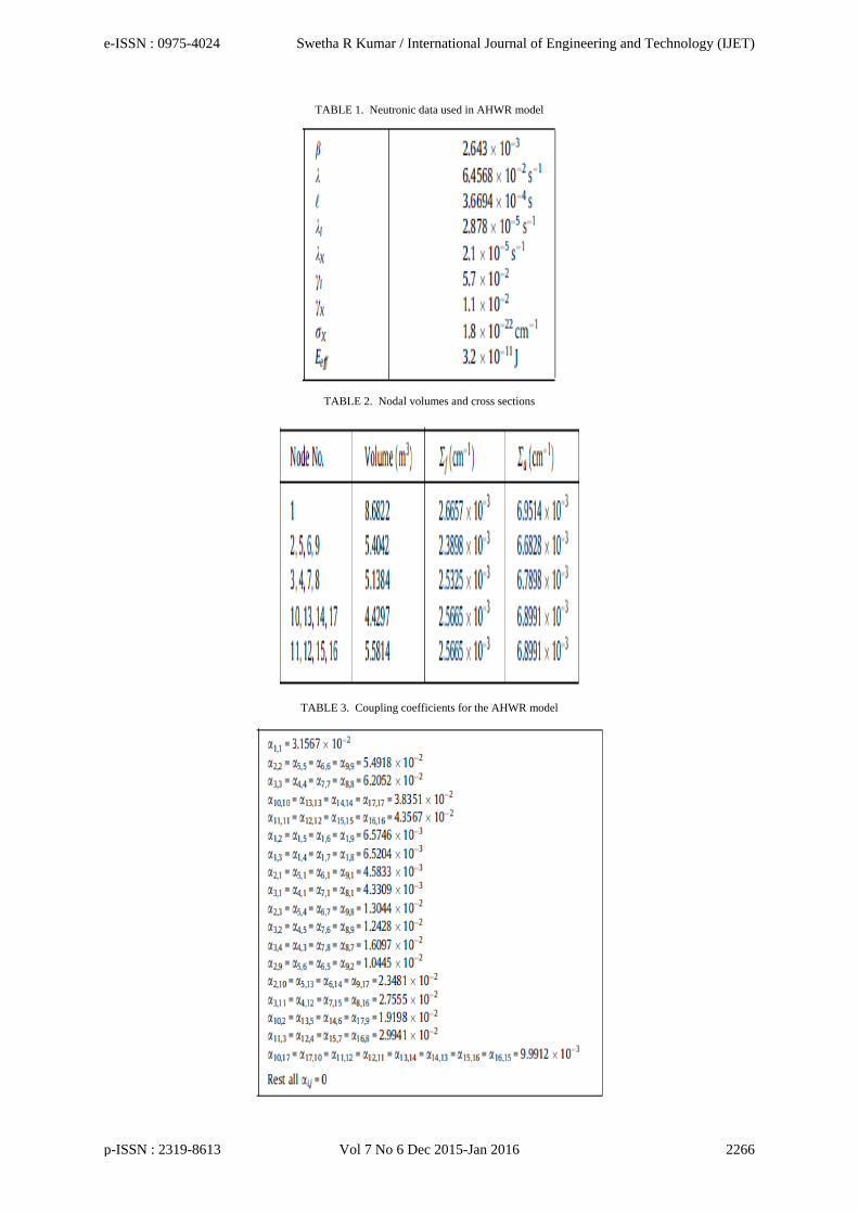
TABLE 1. Neutronic data used in AHWR model
TABLE 2. Nodal volumes and cross sections
TABLE 3. Coupling coefficients for the AHWR model
e-ISSN : 0975-4024 Swetha R Kumar / International Journal of Engineering and Technology (IJET)
p-ISSN : 2319-8613 Vol 7 No 6 Dec 2015-Jan 2016 2266
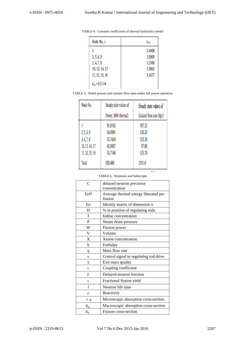
TABLE 4. Constant coefficients of thermal hydraulics model
TABLE 5. Nodal powers and coolant flow rates under full power operation
TABLE 6. Notations and Subscripts
C delayed neutron precursor concentration
Eeff Average thermal energy liberated per fission
En Identity matrix of dimension n H % in position of regulating rods I Iodine concentration P Steam drum pressure W Fission power V Volume X Xenon concentration h Enthalpy q Mass flow rate v Control signal to regulating rod drive x Exit mass quality α Coupling coefficient β Delayed neutron fraction γ Fractional fission yield l Neutron life time ρ Reactivity σa Microscopic absorption cross-section ∈ Macroscopic absorption cross-section ∈ Fission cross-section
e-ISSN : 0975-4024 Swetha R Kumar / International Journal of Engineering and Technology (IJET)
p-ISSN : 2319-8613 Vol 7 No 6 Dec 2015-Jan 2016 2267
V. VECTORIZATION OF THE AHWR
The dynamics equations representing the mathematical model of AHWR can be written in vector/ matrix form to implement in MatLab/Simulink environment. For that, rearrange Eq. (1) of nodal powers as = −α W + ∑ α W + (ρ − β)W + λlC
In the above equation α, β are constants, W , α , C and ρ are column vectors of order 1x17 and α is a matrix of order 17x17. However, each term in this equation becomes a column vector of same dimensions. If scalar multiplication is denoted by ‘∙’, element- wise multiplication is denoted by ‘°’ and array multiplication is denoted by ‘∗’ then the above equation can be rewritten as = ∙ −α °W + ∑ α W + ρ °W − β ∙ W + (λl) ∙ C
Similarly all the equations of AHWR model are expressed in its vectorized form and implemented. VI. DIVISION OF CORE INTO FOUR ZONES
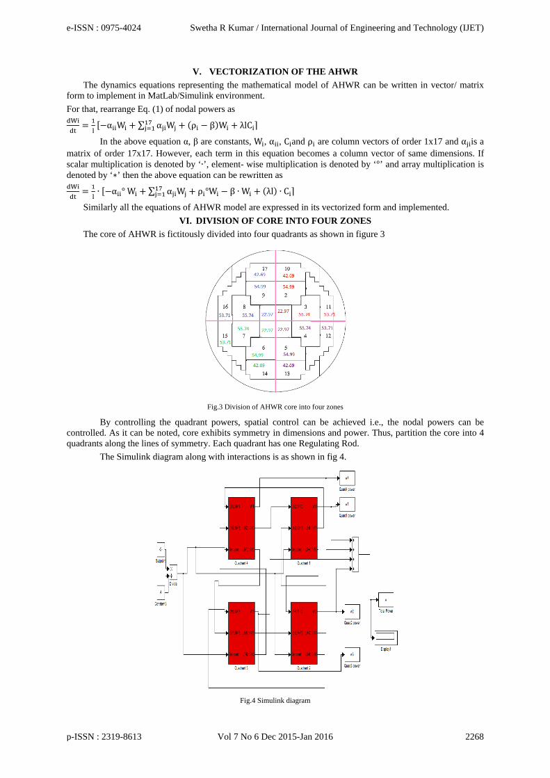
The core of AHWR is fictitously divided into four quadrants as shown in figure 3
Fig.3 Division of AHWR core into four zones
By controlling the quadrant powers, spatial control can be achieved i.e., the nodal powers can be controlled. As it can be noted, core exhibits symmetry in dimensions and power. Thus, partition the core into 4 quadrants along the lines of symmetry. Each quadrant has one Regulating Rod.
The Simulink diagram along with interactions is as shown in fig 4.
Fig.4 Simulink diagram
e-ISSN : 0975-4024 Swetha R Kumar / International Journal of Engineering and Technology (IJET)
p-ISSN : 2319-8613 Vol 7 No 6 Dec 2015-Jan 2016 2268
VII. CONTROLLER DESIGN
A conventional PID controller is designed using relay feedback approach. Optimization of this controller is carried out using Genetic Algorithm.
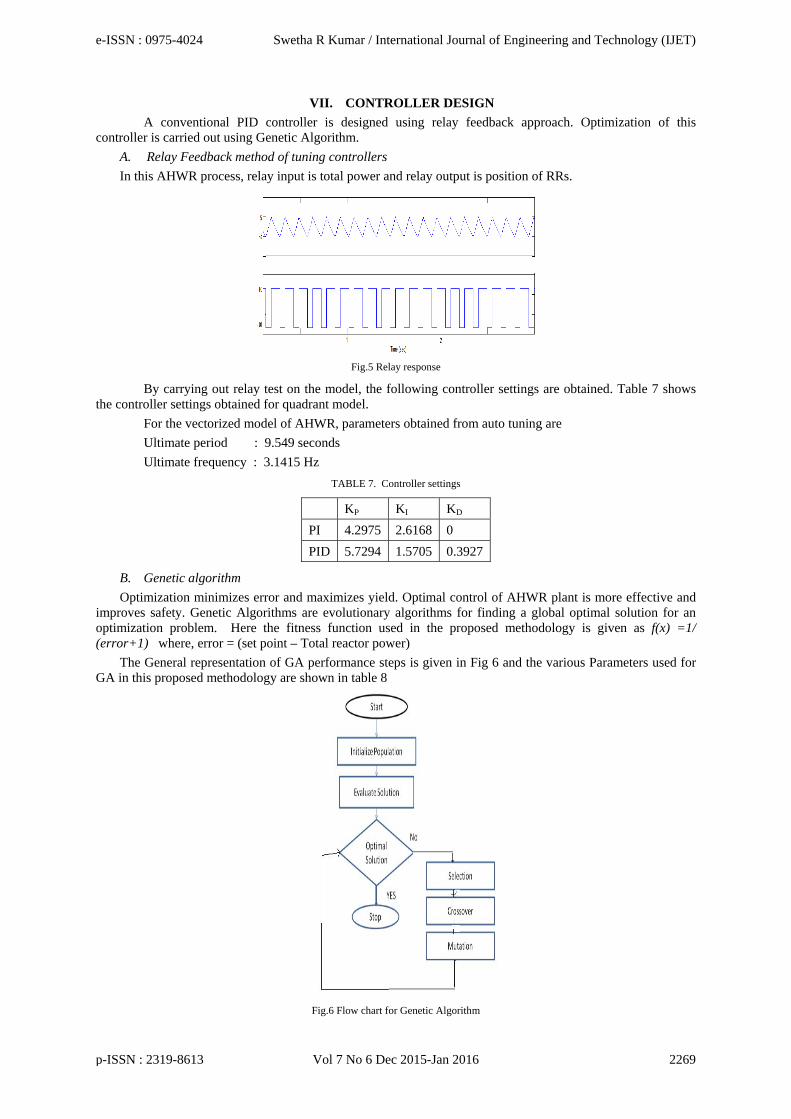
A. Relay Feedback method of tuning controllers
In this AHWR process, relay input is total power and relay output is position of RRs.
Fig.5 Relay response
By carrying out relay test on the model, the following controller settings are obtained. Table 7 shows the controller settings obtained for quadrant model.
For the vectorized model of AHWR, parameters obtained from auto tuning are Ultimate period : 9.549 seconds Ultimate frequency : 3.1415 Hz
TABLE 7. Controller settings
KP KI KD PI 4.2975 2.6168 0 PID 5.7294 1.5705 0.3927
B. Genetic algorithm
Optimization minimizes error and maximizes yield. Optimal control of AHWR plant is more effective and improves safety. Genetic Algorithms are evolutionary algorithms for finding a global optimal solution for an optimization problem. Here the fitness function used in the proposed methodology is given as f(x) =1/ (error+1) where, error = (set point – Total reactor power)
The General representation of GA performance steps is given in Fig 6 and the various Parameters used for GA in this proposed methodology are shown in table 8
Fig.6 Flow chart for Genetic Algorithm
e-ISSN : 0975-4024 Swetha R Kumar / International Journal of Engineering and Technology (IJET)
p-ISSN : 2319-8613 Vol 7 No 6 Dec 2015-Jan 2016 2269
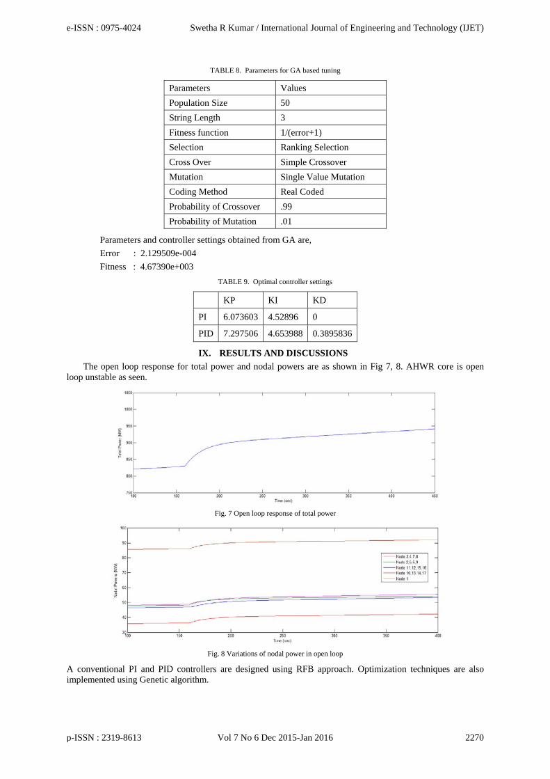
TABLE 8. Parameters for GA based tuning
Parameters Values Population Size 50 String Length 3 Fitness function 1/(error+1) Selection Ranking Selection Cross Over Simple Crossover Mutation Single Value Mutation Coding Method Real Coded Probability of Crossover .99 Probability of Mutation .01
Parameters and controller settings obtained from GA are, Error : 2.129509e-004 Fitness : 4.67390e+003
TABLE 9. Optimal controller settings
KP KI KD
PI 6.073603 4.52896 0
PID 7.297506 4.653988 0.3895836
IX. RESULTS AND DISCUSSIONS
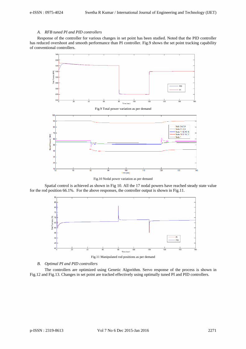
The open loop response for total power and nodal powers are as shown in Fig 7, 8. AHWR core is open loop unstable as seen.
Fig. 7 Open loop response of total power
Fig. 8 Variations of nodal power in open loop
A conventional PI and PID controllers are designed using RFB approach. Optimization techniques are also implemented using Genetic algorithm.
e-ISSN : 0975-4024 Swetha R Kumar / International Journal of Engineering and Technology (IJET)
p-ISSN : 2319-8613 Vol 7 No 6 Dec 2015-Jan 2016 2270
A. RFB tuned PI and PID controllers
Response of the controller for various changes in set point has been studied. Noted that the PID controller has reduced overshoot and smooth performance than PI controller. Fig.9 shows the set point tracking capability of conventional controllers.
Fig.9 Total power variation as per demand
Fig.10 Nodal power variation as per demand
Spatial control is achieved as shown in Fig 10. All the 17 nodal powers have reached steady state value for the rod position 66.1%. For the above responses, the controller output is shown in Fig.11.
Fig.11 Manipulated rod positions as per demand
B. Optimal PI and PID controllers
The controllers are optimized using Genetic Algorithm. Servo response of the process is shown in Fig.12 and Fig.13. Changes in set point are tracked effectively using optimally tuned PI and PID controllers.
e-ISSN : 0975-4024 Swetha R Kumar / International Journal of Engineering and Technology (IJET)
p-ISSN : 2319-8613 Vol 7 No 6 Dec 2015-Jan 2016 2271

Fig.12 Total power variation
Fig.13 Nodal power variation
For these changes in set point, the controller response is as shown below
Fig.14 Manipulated rod position
A disturbance is introduced in the process and the regulatory performance of optimally tuned PID controller is noted. Feed water flow rate is increased by 5% and controlled output is plotted as in Fig.15
Fig.15 Controlled total power output for change in feed flow
Now, comparison between RFB tuned PID controller and optimally tuned PID controller is carried out by plotting the servo responses of both.
e-ISSN : 0975-4024 Swetha R Kumar / International Journal of Engineering and Technology (IJET)
p-ISSN : 2319-8613 Vol 7 No 6 Dec 2015-Jan 2016 2272

Fig.16 Comparison of total power with RFB and GA based optimal PID
X. CONCLUSION
A vectorized nonlinear quadrant model of Advanced Heavy Water Reactor has been developed using the core neutronics and Thermal hydraulics equations. It is essential to control total reactor power and 17 nodal powers due to spatial instability of reactor core.
A conventional PID controller and Optimal PID controller are implemented for controlling the nodal powers by manipulating position of four regulating rods. Servo and regulatory performance of the controller has been studied.
REFERENCES [1] R.K.Munje, B.M.Patre, A.P.Tiwari, Non-linear simulation and control of xenon induced oscillations in Advanced Heavy Water
Reactor, Annals of Nuclear Energy, Vol.64, 2014,pp. 191–200 [2] S.R.Shimjith, A.P.Tiwari, B.Bandyopadhyay and R.K.Patil, Spatial stabilization of Advanced Heavy Water Reactor, Annals of
Nuclear Energy, Vol.38,2011,pp. 1545–1558 [3] R.K.Munje, B.M.Patre, S.R.Shimjith and A. P.Tiwari, Sliding Mode Control for Spatial Stabilization of Advanced Heavy Water
Reactor, IEEE transactions on nuclear science, Vol. 60, No. 4, August 2013 [4] P.S.Londhe, B.M.Patre and A.P.Tiwari, Fuzzy-like PD controller for spatial control of advanced heavy water reactor, Nuclear
Engineering and Design, Vol 274, 2014,pp. 77–89 [5] R.K.Sinha and A.Kakodkar, Design and development of the AHWR—the Indian thorium fuelled innovative nuclear reactor, Nuclear
Engineering and Design, Vol 236, 2006,pp. 683–700 [6] B.Bandyopadhyay, S.R.Shimjith and A.P.Tiwari, Coupled Neutronics Thermal Hydraulics Model of Advanced Heavy Water Reactor
for Control System Studies, India Conference, 2008.INDICON 2008. Annual IEEE, Vol.1, 2008, pp.126-131. [7] P.S.Londhe, B.M.Patre and A.P.Tiwari, Design of Single-Input Fuzzy Logic Controller for Spatial Control of Advanced Heavy Water
Reactor, IEEE transactions on nuclear science, Vol. 61, no. 2,2014. [8] Duderstadt.J.J, Hamilton.L.J, Nuclear Reactor Analysis. John Wiley & Sons Inc., New York, 1983
AUTHOR PROFILE
Ms Swetha R Kumar is working as Assistant professor, Department of Instrumentation and control systems engineering, PSG college of Technology, Coimbatore. She received her M.E degree in Instrumentation Engineering from Madras Institute of Technology, Chennai. Her principle research area is Nuclear power plant instrumentation and control.
e-ISSN : 0975-4024 Swetha R Kumar / International Journal of Engineering and Technology (IJET)
p-ISSN : 2319-8613 Vol 7 No 6 Dec 2015-Jan 2016 2273