veer surendra sai university of technology · transformer is an electro-magnetic energy conversion...
TRANSCRIPT
DEPARTMENT OF ELECTRICAL ENGINEERING
PALLAV DUTTA
LECTURE NOTES ON
ELECTRICAL MACHINES-I
Subject Code - EE 202/EENUGPC04
For B-Tech 4th SEM EE
aliah.ac.in
ALIAH UNIVERSITY Department of Electrical Engineering
Action Area ll-A, 27, Newtown, Kolkata, West Bengal 700160

DEPARTMENT OF ELECTRICAL ENGINEERING
PALLAV DUTTA
Module IV
[TRANSFORMER]
TOPICS Transformers: Single phase transformer, constructional details, core, windings, insulation, tank and conservator, principle of operation, emf equation, magnetising current and core losses, no load and on load operation, Phasor diagram, equivalent circuit, losses and efficiency, condition for maximum efficiency, all-day efficiency, voltage regulation, approximate expression for voltage regulation, direct loading test, indirect loading test, open circuit and short circuit tests, auto transformer, parallel operation of transformers, reason of transformer’s rating in kVA. [Topics are arranged as per above sequence]

DEPARTMENT OF ELECTRICAL ENGINEERING
Pallav Dutta 1 | P a g e
Transformers 4.1 Introduction The transformer is a device that transfers electrical energy from one electrical circuit to another
electrical circuit. The two circuits may be operating at different voltage levels but always work at the
same frequency. Basically, transformer is an electro-magnetic energy conversion device. It is
commonly used in electrical power system and distribution systems. It can change the magnitude of
alternating voltage or current from one value to another. This useful property of transformer is mainly
responsible for the widespread use of alternating currents rather than direct currents i.e., electric
power is generated, transmitted and distributed in the form of alternating current. Transformers have
no moving parts, rugged and durable in construction, thus requiring very little attention. They also
have a very high efficiency as high as 99%.
4.2. Single Phase Transformer A transformer is a static device of equipment used either for raising or lowering the voltage of
an a.c. supply with a corresponding decrease or increase in current. It essentially consists of two
windings, the primary and secondary, wound on a common laminated magnetic core as shown in Fig
1. The winding connected to the a.c. source is called primary winding (or primary) and the one
connected to load is called secondary winding (or secondary). The alternating voltage V1 whose
magnitude is to be changed is applied to the primary.
Depending upon the number of turns of the primary (N1) and secondary (N2), an alternating e.m.f. E2
is induced in the secondary. This induced e.m.f. E2 in the secondary causes a secondary current I2.
Consequently, terminal voltage V2 will appear across the load.
If V2 > V1, it is called a step up-transformer.
If V2 < V1, it is called a step-down transformer.

DEPARTMENT OF ELECTRICAL ENGINEERING
Pallav Dutta 2 | P a g e
Fig. 4.1 Schematic diagram of single-phase transformer
4.3 Constructional Details Depending upon the manner in which the primary and secondary windings are placed on the
core, and the shape of the core, there are two types of transformers, called (a) core type, and (b) shell
type.
4.3.1 Core-type and Shell-type Construction In core type transformers, the windings are placed in the form of concentric cylindrical coils
placed around the vertical limbs of the core. The low-voltage (LV) as well as the high-voltage (HV)
winding are made in two halves, and placed on the two limbs of core. The LV winding is placed next
to the core for economy in insulation cost. Figure 4.1(a) shows the cross-section of the arrangement.
In the shell type transformer, the primary and secondary windings are wound over the central limb of
a three-limb core as shown in Figure 4.1(b). The HV and LV windings are split into a number of
sections, and the sections are interleaved or sandwiched i.e. the sections of the HV and LV windings
are placed alternately.

DEPARTMENT OF ELECTRICAL ENGINEERING
Pallav Dutta 3 | P a g e
Fig: 4.2 Core type & shell type transformer
Core The core is built-up of thin steel laminations insulated from each other. This helps in reducing the
eddy current losses in the core, and also helps in construction of the transformer. The steel used for
core is of high silicon content, sometimes heat treated to produce a high permeability and low
hysteresis loss. The material commonly used for core is CRGO (Cold Rolled Grain Oriented) steel.
Conductor material used for windings is mostly copper. However, for small distribution transformer
aluminum is also sometimes used. The conductors, core and whole windings are insulated using
various insulating materials depending upon the voltage.
Insulating Oil In oil-immersed transformer, the iron core together with windings is immersed in insulating oil. The
insulating oil provides better insulation, protects insulation from moisture and transfers the heat
produced in core and windings to the atmosphere.
The transformer oil should possess the following qualities:
(a) High dielectric strength,
(b) Low viscosity and high purity,
(c) High flash point, and
(d) Free from sludge.
DEPARTMENT OF ELECTRICAL ENGINEERING
Pallav Dutta 4 | P a g e
Transformer oil is generally a mineral oil obtained by fractional distillation of crude oil.
Tank and Conservator The transformer tank contains core wound with windings and the insulating oil. In large transformers
small expansion tank is also connected with main tank is known as conservator. Conservator provides
space when insulating oil expands due to heating. The transformer tank is provided with tubes on the
outside, to permits circulation of oil, which aides in cooling. Some additional devices like breather
and Buchholz relay are connected with main tank. Buchholz relay is placed between main tank and
conservator. It protects the transformer under extreme heating of transformer winding. Breather
protects the insulating oil from moisture when the cool transformer sucks air inside. The silica gel
filled breather absorbs moisture when air enters the tank. Some other necessary parts are connected
with main tank like, Bushings, Cable Boxes, Temperature gauge, Oil gauge, Tappings, etc.
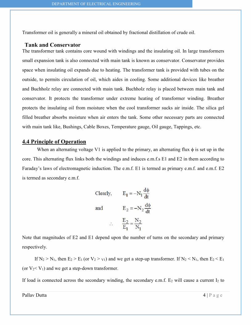
4.4 Principle of Operation When an alternating voltage V1 is applied to the primary, an alternating flux ϕ is set up in the
core. This alternating flux links both the windings and induces e.m.f.s E1 and E2 in them according to
Faraday’s laws of electromagnetic induction. The e.m.f. E1 is termed as primary e.m.f. and e.m.f. E2
is termed as secondary e.m.f.
Note that magnitudes of E2 and E1 depend upon the number of turns on the secondary and primary
respectively.
If N2 > N1, then E2 > E1 (or V2 > V1) and we get a step-up transformer. If N2 < N1, then E2 < E1
(or V2< V1) and we get a step-down transformer.
If load is connected across the secondary winding, the secondary e.m.f. E2 will cause a current I2 to

DEPARTMENT OF ELECTRICAL ENGINEERING
Pallav Dutta 5 | P a g e
flow through the load. Thus, a transformer enables us to transfer a.c. power from one circuit to
another with a change in voltage level.
The following points may be noted carefully:
(a) The transformer action is based on the laws of electromagnetic induction.
(b) There is no electrical connection between the primary and secondary.
(c) The a.c. power is transferred from primary to secondary through magnetic flux.
(d) There is no change in frequency i.e., output power has the same frequency as the input
power.
(e) The losses that occur in a transformer are:
(a) core losses—eddy current and hysteresis losses
(b) copper losses—in the resistance of the windings
In practice, these losses are very small so that output power is nearly equal to the input primary
power. In other words, a transformer has very high efficiency.
4.4.1 E.M.F. Equation of a Transformer Consider that an alternating voltage V1 of frequency f is applied to the primary as shown in
Fig.2.3. The sinusoidal flux ϕ produced by the primary can be represented as:
ϕ=ϕm sinωt When the primary winding is excited by an alternating voltage V1, it is circulating alternating current,
producing an alternating flux ϕ.
ϕ - Flux
ϕm - maximum value of flux
N1 - Number of primary turns
N2 - Number of secondary turns
DEPARTMENT OF ELECTRICAL ENGINEERING
Pallav Dutta 6 | P a g e
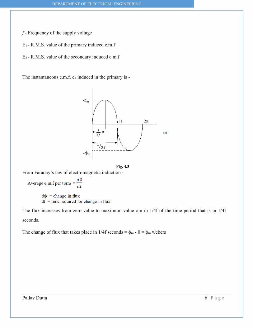
f - Frequency of the supply voltage
E1 - R.M.S. value of the primary induced e.m.f
E2 - R.M.S. value of the secondary induced e.m.f
The instantaneous e.m.f. e1 induced in the primary is -
Fig. 4.3
From Faraday’s law of electromagnetic induction -
The flux increases from zero value to maximum value ϕm in 1/4f of the time period that is in 1/4f
seconds.
The change of flux that takes place in 1/4f seconds = ϕm - 0 = ϕm webers

DEPARTMENT OF ELECTRICAL ENGINEERING
Pallav Dutta 7 | P a g e
4.4.2 Voltage Ratio Voltage transformation ratio is the ratio of e.m.f induced in the secondary winding to the e.m.f induced in the primary winding.
This ratio of secondary induced e.m.f to primary induced e.m.f is known as voltage transformation
ratio
1. If N2>N1 i.e. K>1 we get E2>E1 then the transformer is called step up transformer.
2. If N2< N1 i.e. K<1 we get E2< E2 then the transformer is called step down transformer.

DEPARTMENT OF ELECTRICAL ENGINEERING
Pallav Dutta 8 | P a g e
3. If N2= N1 i.e. K=1 we get E2= E2 then the transformer is called isolation transformer or 1:1
transformer.
4.4.3 Current Ratio Current ratio is the ratio of current flow through the primary winding (I1) to the current flowing
through the secondary winding (I2). In an ideal transformer -
Apparent input power = Apparent output power.
V1I1 = V2I2
Volt-Ampere Rating
i) The transformer rating is specified as the products of voltage and current (VA rating).
ii) On both sides, primary and secondary VA rating remains same. This rating is generally expressed
in KVA (Kilo Volts Amperes rating).
4.4.4 Transformer on No-load a) Ideal transformer
b) Practical transformer
a) Ideal Transformer An ideal transformer is one that has

DEPARTMENT OF ELECTRICAL ENGINEERING
Pallav Dutta 9 | P a g e
(i) No winding resistance
(ii) No leakage flux i.e., the same flux links both the windings
(iii) No iron losses (i.e., eddy current and hysteresis losses) in the core
Although ideal transformer cannot be physically realized, yet its study provides a very powerful tool
in the analysis of a practical transformer. In fact, practical transformers have properties that approach
very close to an ideal transformer.
Fig: 4.4
Consider an ideal transformer on no load i.e., secondary is open-circuited as shown in Fig.2.4 (i). under such conditions, the primary is simply a coil of pure inductance. When an alternating voltage V1 is applied to the primary, it draws a small magnetizing current Im which lags behind the applied voltage by 90°. This alternating current Im produces an alternating flux ϕ which is proportional to and in phase with it. The alternating flux ϕ links both the windings and induces e.m.f. E1 in the primary and e.m.f. E2 in the secondary. The primary e.m.f. E1 is, at every instant, equal to and in opposition to V1 (Lenz’s law). Both e.m.f.s E1 and E2 lag behind flux ϕ by 90°.However, their magnitudes depend upon the number of primary and secondary turns. Fig. 4.4 (ii) shows the phasor diagram of an ideal transformer on no load. Since flux ϕ is common to both the windings, it has been taken as the reference phasor. The primary e.m.f. E1 and secondary e.m.f. E2 lag behind the flux ϕ by 90°. Note that E1 and E2 are in phase. But E1 is equal to V1 and 180° out of phase with it.
4.4.5 Phasor Diagram i) Φ (flux) is reference ii) Im produce ϕ and it is in phase with ϕ, V1 Leads Im by 90˚

DEPARTMENT OF ELECTRICAL ENGINEERING
Pallav Dutta 10 | P a g e
iii) E1 and E2 are in phase and both opposing supply voltage V1, winding is purely inductive So current has to lag voltage by 90˚. iv) The power input to the transformer P = V1.I1. cos (90˚) ……….. (As, cos90˚ = 0)
P= 0 (ideal transformer) b) i) Practical Transformer on no load A practical transformer differs from the ideal transformer in many respects. The practical transformer
has (i) iron losses (ii) winding resistances and (iii) Magnetic leakage
(i) Iron losses. Since the iron core is subjected to alternating flux, there occurs eddy current and
hysteresis loss in it. These two losses together are known as iron losses or core losses. The iron losses
depend upon the supply frequency, maximum flux density in the core, volume of the core etc. It may
be noted that magnitude of iron losses is quite small in a practical transformer.
(ii) Winding resistances. Since the windings consist of copper conductors, it immediately follows
that both primary and secondary will have winding resistance. The primary resistance R1 and
secondary resistance R2 act in series with the respective windings as shown in Fig. When current
flows through the windings, there will be power loss as well as a loss in voltage due to IR drop. This
will affect the power factor and E1 will be less than V1 while V2 will be less than E2.
Consider a practical transformer on no load i.e., secondary on open-circuit as Shown in Fig 4.5.
Fig: 4.5 Phasor diagram of transformer at noload
Here the primary will draw a small current I0 to supply -
DEPARTMENT OF ELECTRICAL ENGINEERING
Pallav Dutta 11 | P a g e
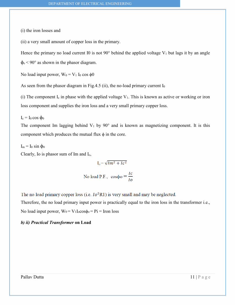
(i) the iron losses and
(ii) a very small amount of copper loss in the primary.
Hence the primary no load current I0 is not 90° behind the applied voltage V1 but lags it by an angle
ϕ0 < 90° as shown in the phasor diagram.
No load input power, W0 = V1 I0 cos ϕ0
As seen from the phasor diagram in Fig.4.5 (ii), the no-load primary current I0
(i) The component Ic in phase with the applied voltage V1. This is known as active or working or iron
loss component and supplies the iron loss and a very small primary copper loss.
Ic = I0 cos ϕ0
The component Im lagging behind V1 by 90° and is known as magnetizing component. It is this
component which produces the mutual flux ϕ in the core.
Im = I0 sin ϕ0
Clearly, Io is phasor sum of Im and Ic,
Therefore, the no load primary input power is practically equal to the iron loss in the transformer i.e.,
No load input power, W0 = V1Iocosϕo = Pi = Iron loss
b) ii) Practical Transformer on Load
DEPARTMENT OF ELECTRICAL ENGINEERING
Pallav Dutta 12 | P a g e
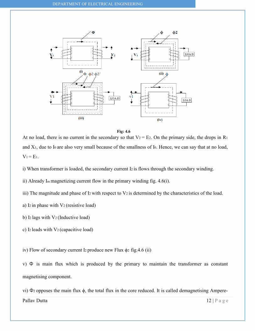
Fig: 4.6
At no load, there is no current in the secondary so that V2 = E2. On the primary side, the drops in R1
and X1, due to I0 are also very small because of the smallness of I0. Hence, we can say that at no load,
V1 = E1.
i) When transformer is loaded, the secondary current I2 is flows through the secondary winding.
ii) Already Im magnetizing current flow in the primary winding fig. 4.6(i).
iii) The magnitude and phase of I2 with respect to V2 is determined by the characteristics of the load.
a) I2 in phase with V2 (resistive load)
b) I2 lags with V2 (Inductive load)
c) I2 leads with V2 (capacitive load)
iv) Flow of secondary current I2 produce new Flux ϕ2 fig.4.6 (ii)
v) Φ is main flux which is produced by the primary to maintain the transformer as constant
magnetising component.
vi) Φ2 opposes the main flux ϕ, the total flux in the core reduced. It is called demagnetising Ampere-
DEPARTMENT OF ELECTRICAL ENGINEERING
Pallav Dutta 13 | P a g e
turns due to this E1 reduced.
vii) To maintain the ϕ constant primary winding draws more current (I2’) from the supply (load
component of primary) and produce ϕ2’ flux which is oppose ϕ2 (but in same direction as ϕ), to
maintain flux constant flux constant in the core fig.4.6 (iii).
viii) The load component current I2’ always neutralizes the changes in the load.
ix) Whatever the load conditions, the net flux passing through the core is approximately the same as at
no-load. An important deduction is that due to the constancy of core flux at all loads, the core loss is
also practically the same under all load conditions fig.4.6 (iv).
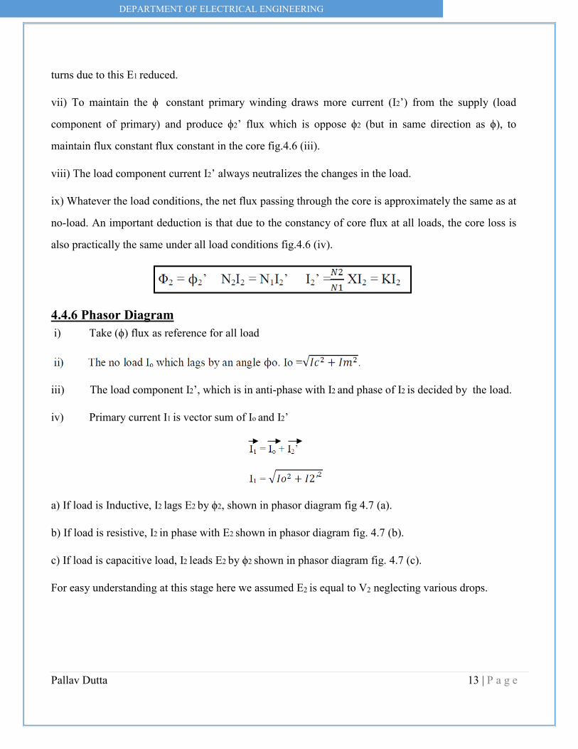
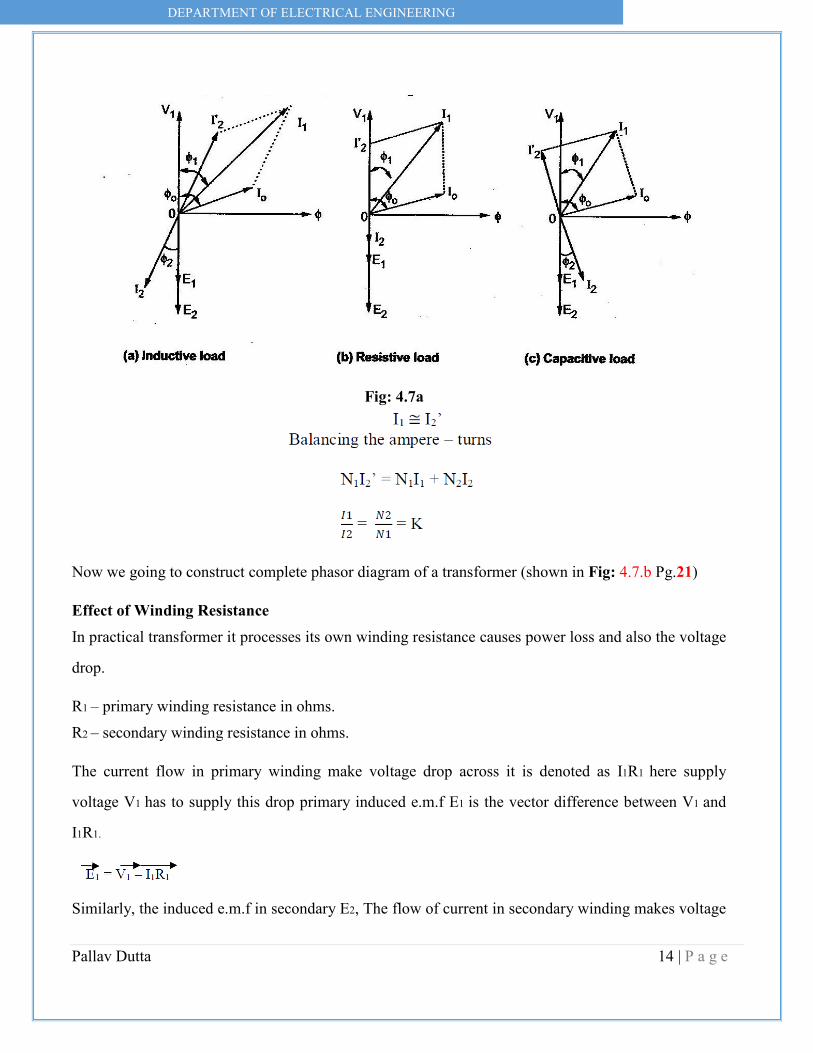
4.4.6 Phasor Diagram i) Take (ϕ) flux as reference for all load
iii) The load component I2’, which is in anti-phase with I2 and phase of I2 is decided by the load.
iv) Primary current I1 is vector sum of Io and I2’
a) If load is Inductive, I2 lags E2 by ϕ2, shown in phasor diagram fig 4.7 (a).
b) If load is resistive, I2 in phase with E2 shown in phasor diagram fig. 4.7 (b).
c) If load is capacitive load, I2 leads E2 by ϕ2 shown in phasor diagram fig. 4.7 (c).
For easy understanding at this stage here we assumed E2 is equal to V2 neglecting various drops.
DEPARTMENT OF ELECTRICAL ENGINEERING
Pallav Dutta 14 | P a g e
Fig: 4.7a
Now we going to construct complete phasor diagram of a transformer (shown in Fig: 4.7.b Pg.21)
Effect of Winding Resistance In practical transformer it processes its own winding resistance causes power loss and also the voltage
drop.
R1 – primary winding resistance in ohms. R2 – secondary winding resistance in ohms.
The current flow in primary winding make voltage drop across it is denoted as I1R1 here supply
voltage V1 has to supply this drop primary induced e.m.f E1 is the vector difference between V1 and
I1R1.
Similarly, the induced e.m.f in secondary E2, The flow of current in secondary winding makes voltage
DEPARTMENT OF ELECTRICAL ENGINEERING
Pallav Dutta 15 | P a g e
drop across it and it is denoted as I2R2 here E2 has to supply this drop.
The vector difference between E2 and I2R2
(Assuming as purely resistive drop here.)
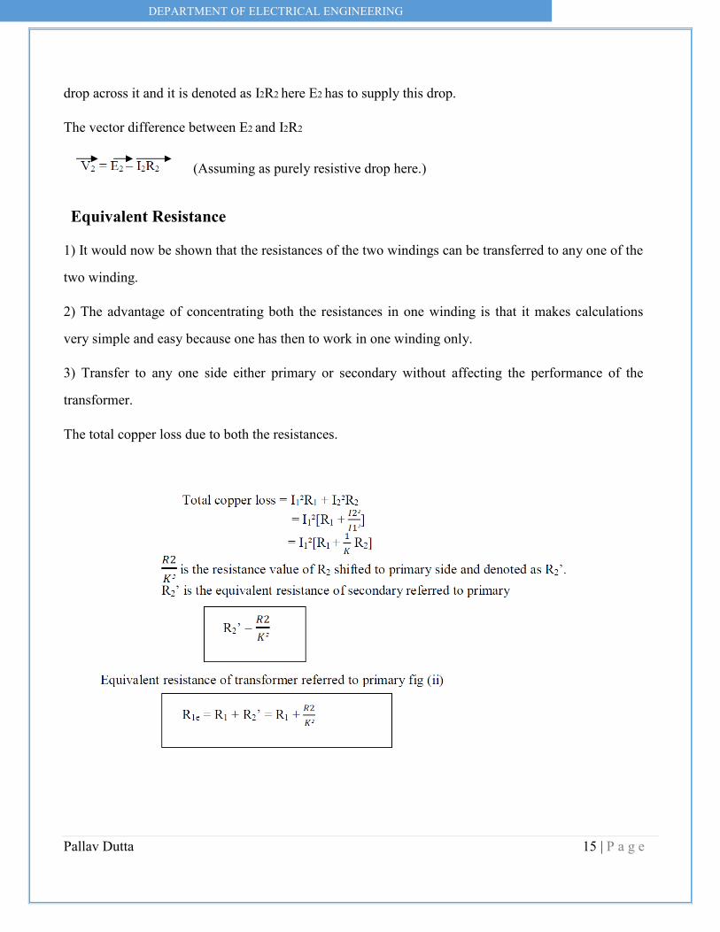
Equivalent Resistance 1) It would now be shown that the resistances of the two windings can be transferred to any one of the
two winding.
2) The advantage of concentrating both the resistances in one winding is that it makes calculations
very simple and easy because one has then to work in one winding only.
3) Transfer to any one side either primary or secondary without affecting the performance of the
transformer.
The total copper loss due to both the resistances.

DEPARTMENT OF ELECTRICAL ENGINEERING
Pallav Dutta 16 | P a g e
Fig:4.8
Similarly, it is possible to refer the equivalent resistance to secondary winding.
DEPARTMENT OF ELECTRICAL ENGINEERING
Pallav Dutta 17 | P a g e
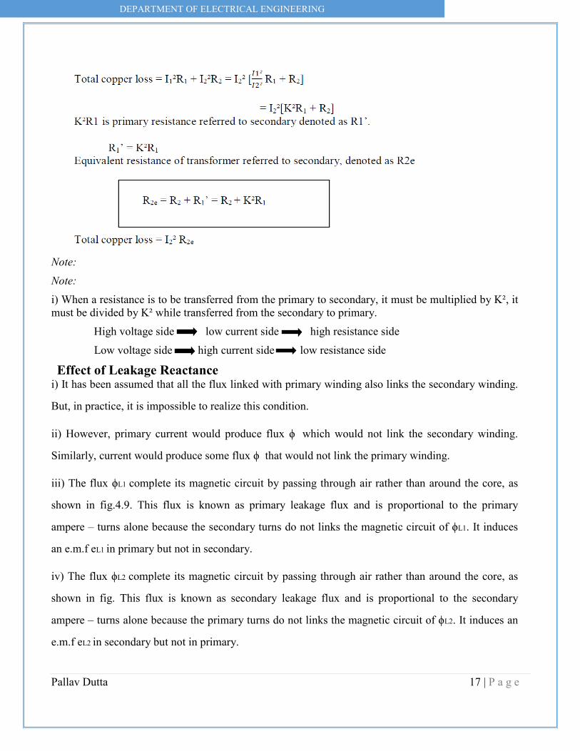
Note: Note: i) When a resistance is to be transferred from the primary to secondary, it must be multiplied by K², it must be divided by K² while transferred from the secondary to primary. High voltage side low current side high resistance side Low voltage side high current side low resistance side
Effect of Leakage Reactance i) It has been assumed that all the flux linked with primary winding also links the secondary winding.
But, in practice, it is impossible to realize this condition.
ii) However, primary current would produce flux ϕ which would not link the secondary winding.
Similarly, current would produce some flux ϕ that would not link the primary winding.
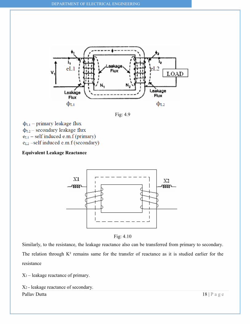
iii) The flux ϕL1 complete its magnetic circuit by passing through air rather than around the core, as
shown in fig.4.9. This flux is known as primary leakage flux and is proportional to the primary
ampere – turns alone because the secondary turns do not links the magnetic circuit of ϕL1. It induces
an e.m.f eL1 in primary but not in secondary.
iv) The flux ϕL2 complete its magnetic circuit by passing through air rather than around the core, as
shown in fig. This flux is known as secondary leakage flux and is proportional to the secondary
ampere – turns alone because the primary turns do not links the magnetic circuit of ϕL2. It induces an
e.m.f eL2 in secondary but not in primary.
DEPARTMENT OF ELECTRICAL ENGINEERING
Pallav Dutta 18 | P a g e
Fig: 4.9
Equivalent Leakage Reactance
Fig: 4.10
Similarly, to the resistance, the leakage reactance also can be transferred from primary to secondary.
The relation through K² remains same for the transfer of reactance as it is studied earlier for the
resistance
X1 – leakage reactance of primary.
X2 - leakage reactance of secondary.

DEPARTMENT OF ELECTRICAL ENGINEERING
Pallav Dutta 19 | P a g e
Then the total leakage reactance referred to primary is X1e given by
Equivalent Impedance The transformer winding has both resistance and reactance (R1, R2, X1,X2).Thus we can say that the
total impedance of primary winding isZ1 which is,
Z1 = R1 + jX1 ohms
On secondary winding,
Z2 = R2 + jX2 ohms
Similar to resistance and reactance, the impedance also can be referred to any one side,

DEPARTMENT OF ELECTRICAL ENGINEERING
Pallav Dutta 20 | P a g e
4.4.7 Complete Phasor Diagram of a Transformer (for Inductive Load or Lagging pf) We now restrict ourselves to the more commonly occurring load i.e. inductive along with resistance,
which has a lagging power factor.
For drawing this diagram, we must remember that

DEPARTMENT OF ELECTRICAL ENGINEERING
Pallav Dutta 21 | P a g e
Fig: 4.7.b
4.5 Equivalent Circuit of Transformer No load equivalent circuit
i) Im produces the flux and is assumed to flow through reactance Xo called no load reactance while Ic is
active component representing core losses hence is assumed to flow through the resistance R0
ii) Equivalent resistance is shown in fig.4.12.
iii) When the load is connected to the transformer then secondary current I2 flows causes voltage drop
across R2 and X2. Due to I2, primary draws an additional current.
I1 is the phasor addition of Io and I2’. This I1 causes the voltage drop across primary resistance R1 and
DEPARTMENT OF ELECTRICAL ENGINEERING
Pallav Dutta 22 | P a g e
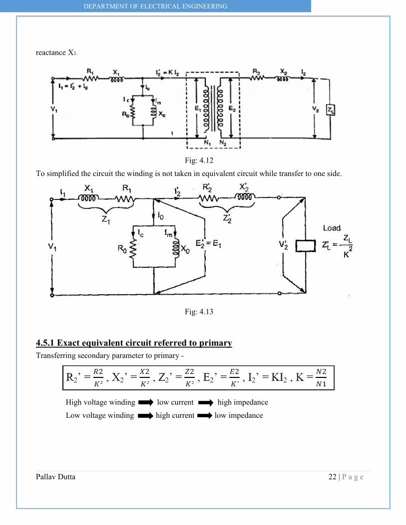
reactance X1.
Fig: 4.12
To simplified the circuit the winding is not taken in equivalent circuit while transfer to one side.
Fig: 4.13
4.5.1 Exact equivalent circuit referred to primary Transferring secondary parameter to primary -
High voltage winding low current high impedance Low voltage winding high current low impedance

DEPARTMENT OF ELECTRICAL ENGINEERING
Pallav Dutta 23 | P a g e
Fig: 4.14
4.5.2 Exact equivalent circuit referred to secondary
Now as long as no load branch i.e. exciting branch is in between Z1 and Z2’, the impedances cannot be
combined. So further simplification of the circuit can be done. Such circuit is called approximate
equivalent circuit.
4.5.3 Approximate Equivalent Circuit i) To get approximate equivalent circuit, shift the no load branch containing Ro and Xo to the left of R1
and X1.
ii) By doing this we are creating an error that the drop across R1 and X1 to Io is neglected due to this
circuit because simpler.
iii) This equivalent circuit is called approximate equivalent circuit Fig: 4.15 & Fig: 4.16.
In this circuit new R1 and R2’ can be combined to get equivalent circuit referred to primary

DEPARTMENT OF ELECTRICAL ENGINEERING
Pallav Dutta 24 | P a g e
R1e,similarly X1 and X2’ can be combined to get X1e.
4.6 Approximate Voltage Drop in a Transformer

DEPARTMENT OF ELECTRICAL ENGINEERING
Pallav Dutta 25 | P a g e
Fig. 2.17
Primary parameter is referred to secondary there are no voltage drop in primary. When there is no
load, I2 = 0 and we get no load terminal voltage drop in
V2o = E2 = no load terminal voltage V2 = terminal voltage on load
4.6.1 For Lagging P.F. i) The current I2 lags V2 by angle ϕ2
ii) Take V2 as reference
iii) I2R2e is in phase with I2 while I2 X2e leads I2 by 90˚
iv) Draw the circle with O as centre and OC as radius cutting extended OA at M. as OA
= V2 and now OM = E2.
v) The total voltage drop is AM = I2Z2e.
vi) The angle α is practically very small and in practice M&N are very close to each other. Due to this
the approximate voltage drop is equal to AN instead of AM
AN – approximate voltage drop
To find AN by adding AD& DN

DEPARTMENT OF ELECTRICAL ENGINEERING
Pallav Dutta 26 | P a g e
AD = AB cosϕ = I2R2e cosϕ
DN = BL sinϕ = I2X2e sinϕ
AN = AD + DN = I2R2e cosϕ2 + I2X2e sinϕ2
Assuming: ϕ2 = ϕ1 = ϕ
Approximate voltage drop = I2R2e cosϕ+I2X2e sinϕ (referred to secondary)
Similarly: Approximate voltage drop = I1R1e cosϕ+I1X1e sinϕ (referred to primary)
Fig:4.18
4.6.2 For Leading P.F Loading I2 leads V2 by angle ϕ2
Approximate voltage drop = I2R2e cosϕ - I2X2e sinϕ (referred to secondary)
Similarly: Approximate voltage drop = I1R1e cosϕ - I1X1e sinϕ (referred to primary)
DEPARTMENT OF ELECTRICAL ENGINEERING
Pallav Dutta 27 | P a g e
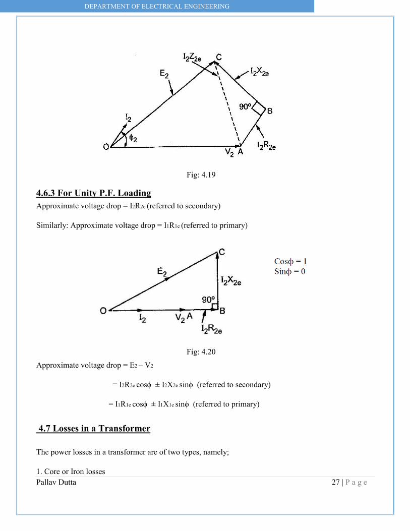
Fig: 4.19
4.6.3 For Unity P.F. Loading Approximate voltage drop = I2R2e (referred to secondary)
Similarly: Approximate voltage drop = I1R1e (referred to primary)
Fig: 4.20
Approximate voltage drop = E2 – V2
= I2R2e cosϕ ± I2X2e sinϕ (referred to secondary)
= I1R1e cosϕ ± I1X1e sinϕ (referred to primary)
4.7 Losses in a Transformer The power losses in a transformer are of two types, namely;
1. Core or Iron losses

DEPARTMENT OF ELECTRICAL ENGINEERING
Pallav Dutta 28 | P a g e
2. Copper losses
These losses appear in the form of heat and produce (i) an increase in Temperature and (ii) a drop in
efficiency.
2.7.1 Core or Iron losses (Pi) These consist of hysteresis and eddy current losses and occur in the transformer core due to the
alternating flux. These can be determined by open-circuit test.
Hysteresis loss = kh f Bm1.6 watts /m3
Kh – hysteresis constant depends on material
f - Frequency
Bm – maximum flux density
Eddy current loss = Ke f2 Bm2t2 watts /m3
Ke – eddy current constant
t - Thickness of the core
Both hysteresis and eddy current losses depend upon
(i) Maximum flux density Bm in the core
(ii) Supply frequency f. Since transformers are connected to constant-frequency, constant voltage
supply, both f and Bm are constant. Hence, core or iron losses are practically the same at all loads.
Iron or Core losses, Pi = Hysteresis loss + Eddy current loss = Constant losses (Pi)
The hysteresis loss can be minimized by using steel of high silicon content. Whereas eddy current loss
can be reduced by using core of thin laminations.
Copper losses (Pcu) These losses occur in both the primary and secondary windings due to their ohmic resistance. These
can be determined by short-circuit test. The copper loss depends on the magnitude of the current
flowing through the windings.

DEPARTMENT OF ELECTRICAL ENGINEERING
Pallav Dutta 29 | P a g e
4.8 Efficiency of a Transformer Like any other electrical machine, the efficiency of a transformer is defined as the ratio of output
power (in watts or kW) to input power (watts or kW) i.e.
Power output = power input – Total losses
Power input = power output + Total losses
= power output + Pi + Pcu
This is full load efficiency and I2 = full load current. We can now find the full-load efficiency of the transformer at any p.f. without actually loading the transformer.

DEPARTMENT OF ELECTRICAL ENGINEERING
Pallav Dutta 30 | P a g e
4.8.1 Condition for Maximum Efficiency Voltage and frequency supply to the transformer is constant the efficiency varies with the load. As
load increases, the efficiency increases. At a certain load current, it loaded further the efficiency start
decreases as shown in fig. 4.21.
Fig: 4.21
The load current at which the efficiency attains maximum value is denoted as I2m a n d maximum
efficiency is denoted as ηmax, now we find –

DEPARTMENT OF ELECTRICAL ENGINEERING
Pallav Dutta 31 | P a g e
(a) condition for maximum efficiency
(b) load current at which ηmax occurs
(c) KVA supplied at maximum efficiency
Considering primary side,
Load output = V1I1 cosϕ1
Copper loss = I12 R1e or I22 R2e
Iron loss = hysteresis + eddy current loss = Pi
Pcu loss = Pi iron loss The output current which will make Pcu loss equal to the iron loss. By proper design, it is possible to
make the maximum efficiency occur at any desired load.
4.8.2 Load current I2m at maximum efficiency

DEPARTMENT OF ELECTRICAL ENGINEERING
Pallav Dutta 32 | P a g e
4.8.3 KVA Supplied at Maximum Efficiency For constant V2 the KVA supplied is the function of load current.

DEPARTMENT OF ELECTRICAL ENGINEERING
Pallav Dutta 33 | P a g e
4.8.4 All Day Efficiency (Energy Efficiency) In electrical power system, we are interested to find out the all-day efficiency of any transformer
because the load at transformer is varying in the different time duration of the day. So all day
efficiency is defined as the ratio of total energy output of transformer to the total energy input in 24
hours.
Here, kWh is kilowatt hour.
4.9 Testing of Transformer The testing of transformer means to determine efficiency and regulation of a transformer at any load
and at any power factor condition.
There are two methods
i) Direct loading test
ii) Indirect loading test
a. Open circuit test b. Short circuit test
i) Load test on transformer This method is also called as direct loading test on transformer because the load is directly connected
to the transformer. We required various meters to measure the input and output reading while change
the load from zero to full load. Fig. 4.22 shows the connection of transformer for direct load test. The
primary is connected through the variac to change the input voltage as we required. Connect the
meters as shown in the figure below.

DEPARTMENT OF ELECTRICAL ENGINEERING
Pallav Dutta 34 | P a g e
Fig: 4.22
The load is varied from no load to full load in desired steps. All the time, keep primary voltage V1
constant at its rated value with help of variac and tabulated the reading. The first reading is to be
noted on no load for which I2 = 0 A and W2 = 0W.
Calculation From the observed reading
W1 = input power to the transformer
W2 = output power delivered to the load
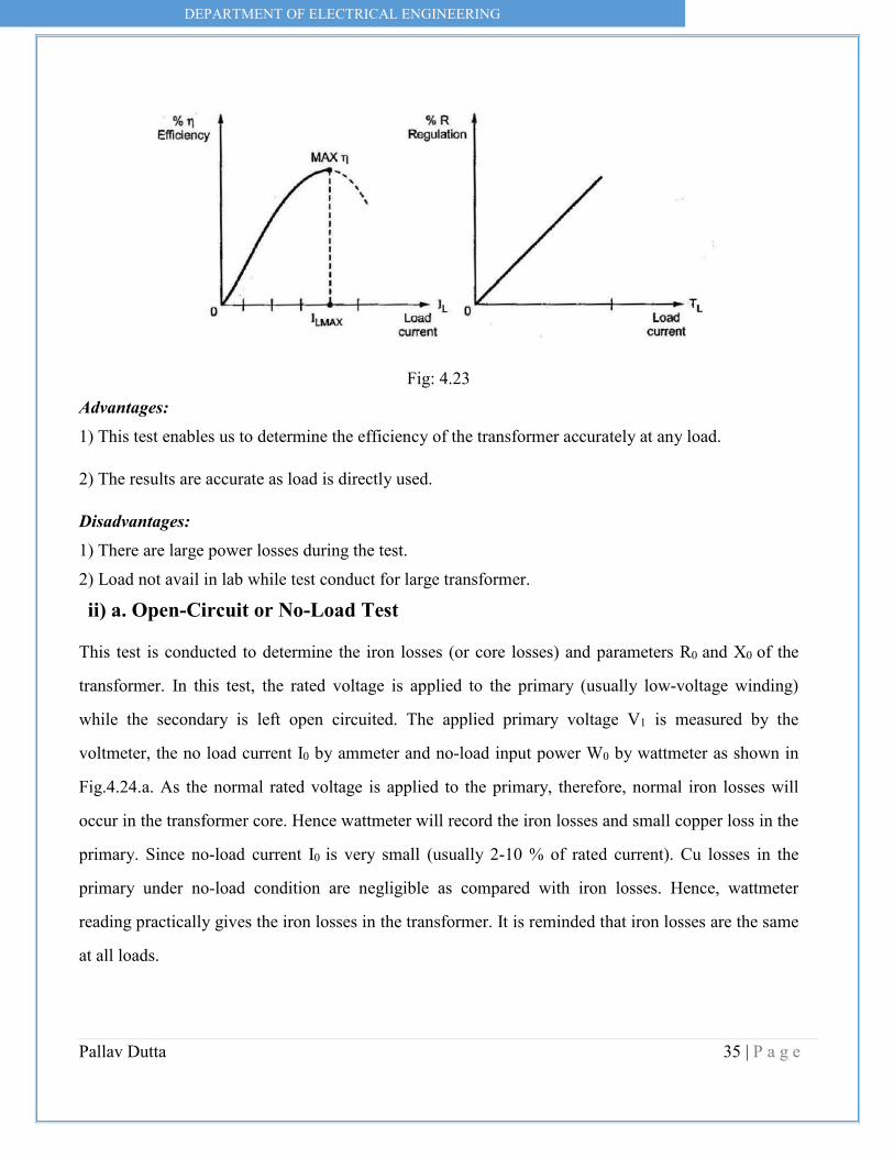
The graph of % η and % R on each load against load current IL is plotted as shown in fig. 4.23.
DEPARTMENT OF ELECTRICAL ENGINEERING
Pallav Dutta 35 | P a g e
Fig: 4.23
Advantages: 1) This test enables us to determine the efficiency of the transformer accurately at any load.
2) The results are accurate as load is directly used.
Disadvantages: 1) There are large power losses during the test. 2) Load not avail in lab while test conduct for large transformer.
ii) a. Open-Circuit or No-Load Test This test is conducted to determine the iron losses (or core losses) and parameters R0 and X0 of the
transformer. In this test, the rated voltage is applied to the primary (usually low-voltage winding)
while the secondary is left open circuited. The applied primary voltage V1 is measured by the
voltmeter, the no load current I0 by ammeter and no-load input power W0 by wattmeter as shown in
Fig.4.24.a. As the normal rated voltage is applied to the primary, therefore, normal iron losses will
occur in the transformer core. Hence wattmeter will record the iron losses and small copper loss in the
primary. Since no-load current I0 is very small (usually 2-10 % of rated current). Cu losses in the
primary under no-load condition are negligible as compared with iron losses. Hence, wattmeter
reading practically gives the iron losses in the transformer. It is reminded that iron losses are the same
at all loads.

DEPARTMENT OF ELECTRICAL ENGINEERING
Pallav Dutta 36 | P a g e
Fig: 4.24.a
Under no load conditions the PF is very low (near to 0) in lagging region. By using the above data we can draw the equivalent parameter shown in Figure 4.24.b.
Fig: 4.24.b
Thus open-circuit test enables us to determine iron losses and parameters R0 and X0 of the transformer.
ii) b. Short-Circuit or Impedance Test

DEPARTMENT OF ELECTRICAL ENGINEERING
Pallav Dutta 37 | P a g e
This test is conducted to determine R1e (or R2e), X1e (or X2e) and full-load copper losses of the
transformer. In this test, the secondary (usually low-voltage winding) is short-circuited by a thick
conductor and variable low voltage is applied to the primary as shown in Fig.4.25. The low input
voltage is gradually raised till at voltage VSC, full-load current I1 flows in the primary. Then I2 in the
secondary also has full-load value since I1/I2 = N2/N1. Under such conditions, the copper loss in the
windings is the same as that on full load. There is no output from the transformer under short-circuit
conditions. Therefore, input power is all loss and this loss is almost entirely copper loss. It is because
iron loss in the core is negligibly small since the voltage VSC is very small. Hence, the wattmeter will
practically register the full load copper losses in the transformer windings.
Fig: 4.25.a

DEPARTMENT OF ELECTRICAL ENGINEERING
Pallav Dutta 38 | P a g e
Fig: 4.25.b From fig: 4.25.b we can calculate,
4.9 Voltage Regulation of Transformer Under no load conditions, the voltage at the secondary terminals is E2 and
(This approximation neglects the drop R1 and Xl1 due to small no load current). As load is applied to
the transformer, the load current or the secondary current increases. Correspondingly, the primary
current I1 also increases. Due to these currents, there is a voltage drop in the primary and secondary
leakage reactances, and as a consequence the voltage across the output terminals or the load terminals
changes. In quantitative terms this change in terminal voltage is called Voltage Regulation.
Voltage regulation of a transformer is defined as the drop in the magnitude of load voltage (or
secondary terminal voltage) when load current changes from zero to full load value. This is expressed
as a fraction of secondary rated voltage.
The secondary rated voltage of a transformer is equal to the secondary terminal voltage at no load (i.e.
E2), this is as per IS.
Voltage regulation is generally expressed as a percentage.
DEPARTMENT OF ELECTRICAL ENGINEERING
Pallav Dutta 39 | P a g e
Note that E2, V2 are magnitudes, and not phasor or complex quantities. Also note that voltage
regulation depends not only on load current, but also on its power factor. Using approximate
equivalent circuit referred to primary or secondary, we can obtain the voltage regulation. From
approximate equivalent circuit referred to the secondary side and phasor diagram for the circuit.
4.10 Auto-transformers The transformers we have considered so far are two-winding transformers in which the
electrical circuit connected to the primary is electrically isolated from that connected to the secondary.
An auto-transformer does not provide such isolation, but has economy of cost combined with
increased efficiency. Fig.4.26 illustrates the auto-transformer which consists of a coil of NA turns
between terminals 1 and 2, with a third terminal 3 provided after NB turns. If we neglect coil
resistances and leakage fluxes, the flux linkages of the coil between 1 and 2 equals NA фm while the
portion of coil between 3 and 2 has a flux linkage NB фm. If the induced voltages are designated as EA
and EB, just as in a two-winding transformer,

DEPARTMENT OF ELECTRICAL ENGINEERING
Pallav Dutta 40 | P a g e
Fig: 4.26
Neglecting the magnetizing ampere-turns needed by the core for producing flux, as in an ideal
transformer, the current IA flows through only (NA – NB) turns. If the load current is IB, as shown by
Kirchhoff’s current law, the current IC flowing from terminal 3 to terminal 2 is (IA - IB). This current
flows through NB turns. So, the requirement of a net value of zero ampere-turns across the core
demands that
Consequently, as far as voltage, current converting properties are concerned, the autotransformer of
Figure: 26 behaves just like a two-winding transformer. However, in the autotransformer we don’t
need two separate coils, each designed to carry full load values of current.
4.11 Parallel Operation of Transformers It is economical to install numbers of smaller rated transformers in parallel than installing a bigger
rated electrical power transformer. This has mainly the following advantages,
To maximize electrical power system efficiency: Generally electrical power transformer gives the

DEPARTMENT OF ELECTRICAL ENGINEERING
Pallav Dutta 41 | P a g e
maximum efficiency at full load. If we run numbers of transformers in parallel, we can switch on only
those transformers which will give the total demand by running nearer to its full load rating for that
time. When load increases, we can switch none by one other transformer connected in parallel to fulfil
the total demand. In this way we can run the system with maximum efficiency.
To maximize electrical power system availability: If numbers of transformers run in parallel, we can
shut down any one of them for maintenance purpose. Other parallel transformers in system will serve
the load without total interruption of power.
To maximize power system reliability: if any one of the transformers run in parallel, is tripped due to
fault of other parallel transformers is the system will share the load, hence power supply may not be
interrupted if the shared loads do not make other transformers over loaded.
To maximize electrical power system flexibility: There is always a chance of increasing or decreasing
future demand of power system. If it is predicted that power demand will be increased in future, there
must be a provision of connecting transformers in system in parallel to fulfil the extra demand
because, it is not economical from business point of view to install a bigger rated single transformer
by forecasting the increased future demand as it is unnecessary investment of money. Again, if future
demand is decreased, transformers running in parallel can be removed from system to balance the
capital investment and its return.
4.11.1 Conditions for Parallel Operation of Transformers When two or more transformers run in parallel, they must satisfy the following conditions for
satisfactory performance. These are the conditions for parallel operation of transformers.
• Same voltage ratio of transformer. • Same percentage impedance. • Same polarity. • Same phase sequence. • Same Voltage Ratio
Same voltage ratio of transformer. If two transformers of different voltage ratio are connected in parallel with same primary supply

DEPARTMENT OF ELECTRICAL ENGINEERING
Pallav Dutta 42 | P a g e
voltage, there will be a difference in secondary voltages. Now say the secondary of these transformers
are connected to same bus, there will be a circulating current between secondaries and therefore
between primaries also. As the internal impedance of transformer is small, a small voltage difference
may cause sufficiently high circulating current causing unnecessary extra I2R loss.
Same Percentage Impedance The current shared by two transformers running in parallel should be proportional to their MVA
ratings. Again, current carried by these transformers are inversely proportional to their internal
impedance. From these two statements it can be said that, impedance of transformers running in
parallel are inversely proportional to their MVA ratings. In other words, percentage impedance or per
unit values of impedance should be identical for all the transformers that run in parallel.
Same Polarity Polarity of all transformers that run in parallel, should be the same otherwise huge circulating current
that flows in the transformer but no load will be fed from these transformers. Polarity of transformer
means the instantaneous direction of induced emf in secondary. If the instantaneous directions of
induced secondary emf in two transformers are opposite to each other when same input power is fed
to both of the transformers, the transformers are said to be in opposite polarity. If the instantaneous
directions of induced secondary e.m.f in two transformers are same when same input power is fed to
the both of the transformers, the transformers are said to be in same polarity.
Same Phase Sequence The phase sequence or the order in which the phases reach their maximum positive voltage, must be
identical for two parallel transformers. Otherwise, during the cycle, each pair of phases will be short
circuited.
The above said conditions must be strictly followed for parallel operation of transformers but totally
identical percentage impedance of two different transformers is difficult to achieve practically, that is
why the transformers run in parallel may not have exactly same percentage impedance but the values
would be as nearer as possible.

DEPARTMENT OF ELECTRICAL ENGINEERING
Pallav Dutta 43 | P a g e
4.12 Why Transformer Rating in kVA? An important factor in the design and operation of electrical machines is the relation between
the life of the insulation and operating temperature of the machine. Therefore, temperature rise
resulting from the losses is a determining factor in the rating of a machine. We know that copper loss
in a transformer depends on current and iron loss depends on voltage. Therefore, the total loss in a
transformer depends on the volt-ampere product only and not on the phase angle between voltage and
current i.e., it is independent of load power factor. For this reason, the rating of a transformer is in
kVA and not kW.
References:
[1] P.S. Bimbhra, Electrical Machinery, Khanna Pub, 7th Ed.
[2] P.S. Bimbhra, Generalized Theory of Electrical Machine, Khanna Pub., 2nd Ed.
[3] M.G. Say, The Performance and Design of Alternating Current Machines, CBS Pub., 3rd Ed.
[4] A.E. Fitzgerald, S.D. Umans, C. Kingsley Jr., Electric Machinery, McGraw Hill Education (India) Pvt. Ltd., 6th
Ed.
[5] A.S. Langsdorf, Theory of Alternating Current Machinery, McGraw Hill Education (India) Pvt. Ltd., 2nd Ed.
[6] T.C. Lloyd, A.F. Puchstein and A.G. Conrad, Alternating-Current Machines, John Wiley& Sons pub., 3rd Ed.
[7] Irving Kosow, Electric Machinery and Transformers, Pearson India, 2nd Ed.
[8] C.L. Dawes, A course in Electrical Engineering, Vol-I, Vol-II, McGraw Hill Book Company Inc.
[9] P.K. Mukherjee & S. Chakravorty, Electrical Machines, Dhanpat Rai Publications, 2nd Ed.
[10] I. J Nagrath & D.P. Kothari, Electrical Machines, McGraw Hill Education (India) Pvt. Ltd., 4th Ed.
[11] N.N. Parker Smith, Problems in Electrical Engineering, CBS Pub. 9th Ed.
Apart from this lecture note students are strongly recommended to follow the above-mentioned books
in the references and confer with the faculty/teacher for thorough knowledge of this authoritative
subject of electrical engineering.
Best of Luck to All the Students