vega505ee service manual - english valid from serial number
TRANSCRIPT
60600003
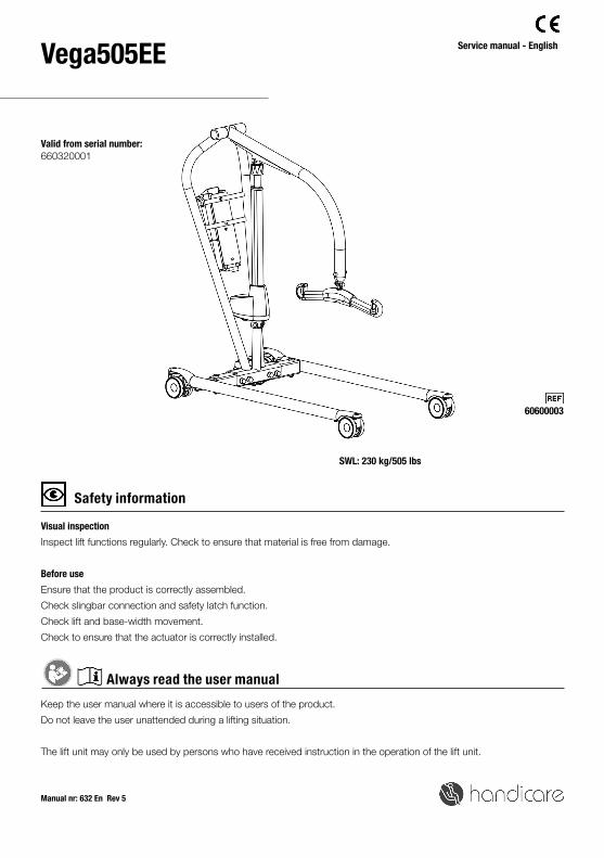
Vega505EE
660320001
Manual nr: 632 En Rev 5
Service manual - English
SWL: 230 kg/505 lbs
Visual inspection
Inspect lift functions regularly. Check to ensure that material is free from damage.
Before use
Ensure that the product is correctly assembled.
Check slingbar connection and safety latch function.
Check lift and base-width movement.
Check to ensure that the actuator is correctly installed.
Keep the user manual where it is accessible to users of the product.
Do not leave the user unattended during a lifting situation.
The lift unit may only be used by persons who have received instruction in the operation of the lift unit.
Safety information
Always read the user manual
Valid from serial number:

2 S E R V I C E M A N U A L
Table of contents
Assembly
-Final inspection ...................................................................................... 3
Using the product
- Important information ............................................................................ 4
- Trouble-shooting ................................................................................... 4
Exploded view and components .......................................... 5-6
Spare part list ...........................................................................11-12
Changing spare parts ............................................................13-14
Periodic inspection - protocol ....................................................15
- Description for periodic inspection .........................................................16
- Periodic inspection - instruction ....................................................... 17-18
Maintenance .................................................................................19
Symbols ..........................................................................................20
Technical information .............................................................20
- Dimensions .....................................................................................21-22
3S E R V I C E M A N U A L
AssemblyFinal inspection
Check to ensure that no parts have been left in the packaging.
Inspect the lift for signs of wear and damage.
Check all four castor wheels and castor wheel locks.
Check all connections and fixtures including screws and bolts.
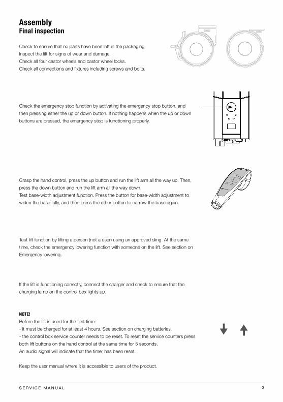
Check the emergency stop function by activating the emergency stop button, and
then pressing either the up or down button. If nothing happens when the up or down
buttons are pressed, the emergency stop is functioning properly.
Grasp the hand control, press the up button and run the lift arm all the way up. Then,
press the down button and run the lift arm all the way down.
Test base-width adjustment function. Press the button for base-width adjustment to
widen the base fully, and then press the other button to narrow the base again.
Test lift function by lifting a person (not a user) using an approved sling. At the same
time, check the emergency lowering function with someone on the lift. See section on
Emergency lowering.
If the lift is functioning correctly, connect the charger and check to ensure that the
charging lamp on the control box lights up.
NOTE!
Before the lift is used for the first time:
- it must be charged for at least 4 hours. See section on charging batteries.
- the control box service counter needs to be reset. To reset the service counters press
both lift buttons on the hand control at the same time for 5 seconds.
An audio signal will indicate that the timer has been reset.
Keep the user manual where it is accessible to users of the product.
4 S E R V I C E M A N U A L
Trouble shooting
If the lift or base-width adjustment cannot be activated, check the following:
- That the emergency stop button is not pressed in.
- That all cables are properly and securely connected. Pull out the contact and plug it in again firmly.
- That battery charging is not in progress.
- That the battery is charged.
If the lift is not working properly, contact your dealer.
If the lift makes unusual noises:
- Try to determine the source of the sound. Take the lift out of operation and contact your dealer.
Using the product
Important Information
• The lift must be assembled according to the instructions provided by Handicare.
• The lift may only be used indoors and on a level floor.
• Lifting accessories must be properly fitted and tested in relation to the user’s needs and functional ability.
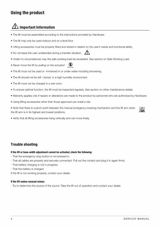
• Do not leave the user unattended during a transfer situation.
• Under no circumstances may the safe working load be exceeded. See section on Safe Working Load.
• Never move the lift by pulling on the actuator!
• The lift must not be used or immersed in or under water including showering.
• The lift should not be left / stored in a high humidity environment.
• The lift must not be charged in a wet room.
• To ensure optimal function, the lift must be inspected regularly. See section on other maintenance details.
• Warranty applies only if repairs or alterations are made to the product by personnel who are authorized by Handicare.
• Using lifting accessories other than those approved can entail a risk.
• Note that there is a pinch point between the manual emergency lowering mechanism and the lift arm when
the lift arm is in its highest and lowest positions.
• Verify that all lifting accessories hang vertically and can move freely.

5S E R V I C E M A N U A L
ITEM
NO
.TI
TLE
QTY
.
1B
ase
Ve
ga
50
5E
E1
2V
eg
a m
ast
1
3Slin
gB
ar
M f
ram
e1
4M
6S D
IN 9
31
8.8
M8
x4
0 f
zb1
5Sle
ev
e 1
0x8
x2
61
6W
ash
er
DIN
12
5 8
.4x1
6x1
.6 f
zb1
7Lo
ck n
ut
DIN
98
5 M
8 f
zb1
8N
ut
co
ve
r M
SM
8G
2
9H
B3
00
21
-01
(H
an
d c
on
tro
l HB
32
4 b
utt
on
)1
10
Sw
ift
ho
ok
1
11
Loc
k n
ut
DIN
98
5 C
L6 M
12
fzb
4
12
Sh
ou
lde
r b
olt c
ov
er
M1
2 G
4
13
Ba
tte
ry c
ov
er
Lin
ak 0
09
40
06
21
14
Nu
t c
ov
er
MSM
12
G4
15
Sh
ou
lde
r b
olt ISO
73
79
12
.9 1
6xM
12
x7
54
16
Wa
she
r D
IN4
33
17
x2
8x2
,5 A
48
5 37 6
16
13
89
11
12
15
16
4
1
10
2
14
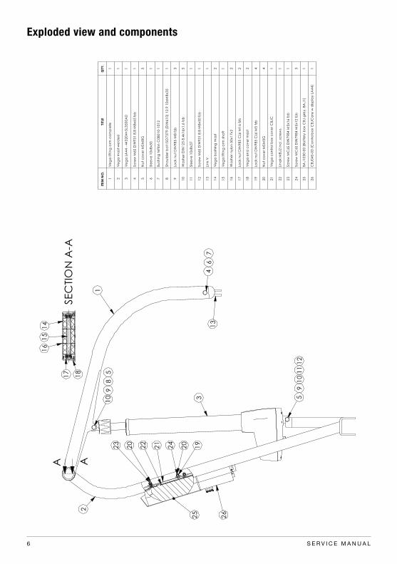
Exploded view and components
6 S E R V I C E M A N U A L
15
14
SEC
TIO
N A
-A1
7
16
18
ITE
M N
O.
TITL
EQ
TY.
1V
eg
a li
ftin
g a
rm c
om
ple
te1
2V
eg
a m
ast
we
lde
d1
3V
eg
a L
A4
4 -
44
32
04
+5
L35
00
A0
1
4Sc
rew
M6
S D
IN9
31
8.8
M8
x6
5 f
zb1
5N
ut
co
ve
r M
SM
8G
5
6Sle
ev
e 1
0x8
x5
01
7B
ush
ing
te
flo
n C
0B
01
0-1
01
21
8Sh
ou
lde
r b
olt ISO
73
79
(D
IN6
10
) 1
2.9
10
xM
8x3
51
9Lo
ck n
ut
DIN
98
5 M
8 f
zb3
10
Wa
she
r D
IN1
25
8.4
x1
6x1
.6 f
zb5
11
Sle
ev
e 1
0x8
x3
71
12
Sc
rew
M6
S D
IN9
31
8.8
M8
x5
0 f
zb1
13
Lin
k V
1
14
Ve
ga
bu
shin
g m
ast
2
15
Ve
ga
lift
ing
arm
sh
aft
1
16
Wa
she
r n
ylo
n 5
0x1
7x2
2
17
Loc
k n
ut
DIN
98
5 C
L6 M
16
fzb
2
18
Ve
ga
en
d c
ov
er
ma
st2
19
Loc
k n
ut
DIN
98
5 C
L6 M
5 f
zb4
20
Nu
t c
ov
er
MSM
5G
4
21
Ve
ga
co
ntr
ol b
ox c
ov
er
CB
JC
1
22
Lin
ak M
BJ
2 in
cl.
scre
ws
1
23
Sc
rew
MC
6S D
IN7
98
4 M
5x1
6 f
zb1
24
Sc
rew
MC
6S D
IN7
98
4 M
5x1
2 f
zb3
25
BA
J1
03
0-0
0 (
Ba
tte
ry b
ox C
BJ
gre
y,
BA
J1
)1
26
CB
J0
45
-00
(C
on
tro
lbo
x C
BJ
Ca
re w
dis
pla
y L
A4
4)
1
22
4
8
13
1
9
2
10
3 5
5 11
21
23
20
19
20
26
9
24
6
12
25
10
7
A A
Exploded view and components

7S E R V I C E M A N U A L
10
16
20
25
7
174 5 143
8
23
2
18
13
19
11
22
12
6
21
1
91
5
24
26
ITE
M N
O.
TITL
EQ
TY.
1V
eg
a le
g r
igh
t a
sm1
2V
eg
a le
g le
ft a
sm1
3Sh
ou
lde
r b
olt ISO
73
79
12
.9 1
6xM
12
x6
52
4Lo
ck n
ut
DIN
98
5 C
L6 M
12
fzb
2
5W
ash
er
DIN
12
5 1
3x2
5x2
.5 f
zb2
6Sc
rew
K6
S D
IN7
38
0 8
.8 M
8x2
0 f
zb2
7B
rac
ke
t a
ctu
ato
r c
en
ter
1
8Sle
ev
e 1
0x8
x2
62
9W
ash
er
DIN
12
5 8
.4x1
6x1
.6 f
zb4
10
M6
S D
IN 9
31
8.8
M8
x4
0 f
zb2
11
Nu
t c
ov
er
MSM
8G
4
12
Loc
k n
ut
DIN
98
5 M
8 f
zb2
13
Leg
sp
rea
d a
ctu
ato
r LA
23
-23
00
06
-03
1
14
Sh
ou
lde
r b
olt c
ov
er
M1
2 G
2
15
Ve
ga
ce
nte
r se
ctio
n w
eld
ed
1
16
Nu
t c
ov
er
MSM
12
G2
17
Wa
she
r B
K1
SF
16
x3
0x1
,52
18
Leg
sp
rea
din
g c
en
ter
asm
1
19
Circ
lip S
GA
DIN
47
1 1
0m
m1
20
Wa
she
r B
K1
SF
10
x2
0x1
,51
21
Leg
sp
rea
din
g a
rm2
22
Ra
dia
l be
arin
g B
K1
8x8
4
23
SG
A C
IRC
LIP
DIN
47
1 8
mm
2
24
Ra
dia
l be
arin
g B
K1
10
x1
21
25
Wa
she
r D
IN1
00
8x1
6x1
,25
fzb
2
26
Sh
im w
ash
er
DIN
98
8 1
8x2
5x0
,52
10
16
20
25
7
174 5 143
8
23
2
18
13
19
11
22
12
6
21
1
91
5
24
26
ITE
M N
O.
TITL
EQ
TY.
1V
eg
a le
g r
igh
t a
sm1
2V
eg
a le
g le
ft a
sm1
3Sh
ou
lde
r b
olt ISO
73
79
12
.9 1
6xM
12
x6
52
4Lo
ck n
ut
DIN
98
5 C
L6 M
12
fzb
2
5W
ash
er
DIN
12
5 1
3x2
5x2
.5 f
zb2
6Sc
rew
K6
S D
IN7
38
0 8
.8 M
8x2
0 f
zb2
7B
rac
ke
t a
ctu
ato
r c
en
ter
1
8Sle
ev
e 1
0x8
x2
62
9W
ash
er
DIN
12
5 8
.4x1
6x1
.6 f
zb4
10
M6
S D
IN 9
31
8.8
M8
x4
0 f
zb2
11
Nu
t c
ov
er
MSM
8G
4
12
Loc
k n
ut
DIN
98
5 M
8 f
zb2
13
Leg
sp
rea
d a
ctu
ato
r LA
23
-23
00
06
-03
1
14
Sh
ou
lde
r b
olt c
ov
er
M1
2 G
2
15
Ve
ga
ce
nte
r se
ctio
n w
eld
ed
1
16
Nu
t c
ov
er
MSM
12
G2
17
Wa
she
r B
K1
SF
16
x3
0x1
,52
18
Leg
sp
rea
din
g c
en
ter
asm
1
19
Circ
lip S
GA
DIN
47
1 1
0m
m1
20
Wa
she
r B
K1
SF
10
x2
0x1
,51
21
Leg
sp
rea
din
g a
rm2
22
Ra
dia
l be
arin
g B
K1
8x8
4
23
SG
A C
IRC
LIP
DIN
47
1 8
mm
2
24
Ra
dia
l be
arin
g B
K1
10
x1
21
25
Wa
she
r D
IN1
00
8x1
6x1
,25
fzb
2
26
Sh
im w
ash
er
DIN
98
8 1
8x2
5x0
,52
Exploded view and components

8 S E R V I C E M A N U A L
57
12
2
98
1 4
10
63
11
ITEM
NO
.TI
TLE
QTY
.
1V
eg
a le
g le
ft w
eld
ed
1
2Fro
nt
Fo
rk V
eg
a 0
31
3R
ad
ial b
ea
rin
g B
K1 1
6x25
2
4Sc
rew
K6S D
IN73
80
8.8
M8x20
fzb
1
5Lo
ck n
ut
DIN
98
5 C
L6 M
10
FZB
2
6Sc
rew
_K6S_IS
O7
38
0_10
.9_M
8x25
_fz
b1
7R
ea
r w
he
el 10
0m
m1
8Sc
rew
MF6S D
IN79
91
8.8
M10
x90
fzb
1
9R
ea
r fo
rk 1
25 m
m1
10
Sc
rew
MF6S D
IN79
91
8.8
M10
x80
fzb
1
11
Fro
nt
wh
ee
l 10
0m
m1
12
Wh
ee
l b
um
pe
r2
Exploded view and components

9S E R V I C E M A N U A L
537
4
61
125
1 S
crew
no.
13
mee
ts th
e op
posit
e sc
rew
at t
he c
ente
r. (L
1 =
L2).
2 S
crew
no.
9, 1
0 an
d 1
1 ar
e ap
plie
d w
ith 4
Nm
and
Loc
tite
2701
.
40
A
L2 L1
DET
AIL
A
SCA
LE 1
: 11
121
68
13 7
11
103
2
45
92
2
ITEM
NO
.DO
CUM
ENT N
O.
REV.
TITLE
QTY
.1
9000
1588
01M
ainf
ram
e Sl
ingB
ar1
290
0014
4801
Slid
e be
arin
g 20
x24x
15 P
A66
1
390
0015
8902
Supp
ort p
in1
490
0014
4701
Nee
dle
rolle
r thr
ust b
earin
g w
ashe
r A
S203
52
590
0014
4601
Nee
dle
bea
ring
AXK
203
51
690
0015
86-0
0203
Tube
for S
lingB
ar2
790
0015
8702
Hook
for S
lingB
ar2
890
0015
9102
Car
go b
arrie
r2
990
0015
9702
Scre
w P
6SS
DIN
931
8.8
M6x
45 fz
b2
1090
0014
4902
Scre
w P
6SS
DIN
931
8.8
M6x
40 fz
b2
1190
0015
9602
Scre
w P
6SS
DIN
931
8.8
M6x
25 fz
b4
1290
0005
1202
Circ
lip S
GA
20
DIN
471
1
1390
0015
9802
Scre
w K
6S IS
O73
80 8
.8 M
5x12
fzb
4
REVI
SIO
N H
ISTO
RY
REV.
DESC
RIPT
ION
DATE
APP
ROVE
D
0290
0011
79_D
ecal
rem
oved
2011
-09-
01hc
-mab
r
03C
hang
e in
900
0158
720
11-0
9-22
hc-m
abr
04C
hang
e in
900
0158
920
12-0
3-15
hc-m
aho
05Sc
rew
s (-1
449,
-159
6, -1
597,
-159
8) c
hang
ed to
FZB
; 90
0015
90 re
mov
ed20
13-0
8-21
hc-a
ndbo
l
06Re
visio
n of
900
0158
6 ch
ange
d20
14-1
1-13
hc-m
akn
07Re
visio
n of
900
0159
1 ch
ange
d20
15-0
2-09
hc-m
akn
D E FC
12
34
BA
32
15
C D
46
78
A B
SCA
LE:1
:10
DW
G.
NO
.RE
V.
NA
ME
DA
TE
DRA
WN
APP
ROV
ED B
Y
SHEE
T 1 O
F 1
WEI
GHT
:
CO
MM
ENTS
:
STA
TUS:
TITLE
MA
TERI
AL:
SIZE
Rele
ased
Slin
gBar
M fr
ame
9000
1662
07
1540
g
2015
-02-
11
A3
Unle
ss o
ther
wise
stat
ed, g
ener
al
tole
ranc
es a
ccor
din
g to
ISO
276
8-m
hc-m
akn
537
4
61
125
1 S
crew
no.
13
mee
ts th
e op
posit
e sc
rew
at t
he c
ente
r. (L
1 =
L2).
2 S
crew
no.
9, 1
0 an
d 1
1 ar
e ap
plie
d w
ith 4
Nm
and
Loc
tite
2701
.
40
A
L2 L1 D
ETA
IL A
SC
ALE
1 :
11
121
68
13 7
11
103
2
45
92
2
ITEM
NO
.DO
CUM
ENT N
O.
REV.
TITLE
QTY
.1
9000
1588
01M
ainf
ram
e Sl
ingB
ar1
290
0014
4801
Slid
e be
arin
g 20
x24x
15 P
A66
1
390
0015
8902
Supp
ort p
in1
490
0014
4701
Nee
dle
rolle
r thr
ust b
earin
g w
ashe
r A
S203
52
590
0014
4601
Nee
dle
bea
ring
AXK
203
51
690
0015
86-0
0203
Tube
for S
lingB
ar2
790
0015
8702
Hook
for S
lingB
ar2
890
0015
9102
Car
go b
arrie
r2
990
0015
9702
Scre
w P
6SS
DIN
931
8.8
M6x
45 fz
b2
1090
0014
4902
Scre
w P
6SS
DIN
931
8.8
M6x
40 fz
b2
1190
0015
9602
Scre
w P
6SS
DIN
931
8.8
M6x
25 fz
b4
1290
0005
1202
Circ
lip S
GA
20
DIN
471
1
1390
0015
9802
Scre
w K
6S IS
O73
80 8
.8 M
5x12
fzb
4
REVI
SIO
N H
ISTO
RY
REV.
DESC
RIPT
ION
DATE
APP
ROVE
D
0290
0011
79_D
ecal
rem
oved
2011
-09-
01hc
-mab
r
03C
hang
e in
900
0158
720
11-0
9-22
hc-m
abr
04C
hang
e in
900
0158
920
12-0
3-15
hc-m
aho
05Sc
rew
s (-1
449,
-159
6, -1
597,
-159
8) c
hang
ed to
FZB
; 90
0015
90 re
mov
ed20
13-0
8-21
hc-a
ndbo
l
06Re
visio
n of
900
0158
6 ch
ange
d20
14-1
1-13
hc-m
akn
07Re
visio
n of
900
0159
1 ch
ange
d20
15-0
2-09
hc-m
akn
D E FC
12
34
BA
32
15
C D
46
78
A B
SCA
LE:1
:10
DW
G.
NO
.RE
V.
NA
ME
DA
TE
DRA
WN
APP
ROV
ED B
Y
SHEE
T 1 O
F 1
WEI
GHT
:
CO
MM
ENTS
:
STA
TUS:
TITLE
MA
TERI
AL:
SIZE
Rele
ased
Slin
gBar
M fr
ame
9000
1662
07
1540
g
2015
-02-
11
A3
Unle
ss o
ther
wise
stat
ed, g
ener
al
tole
ranc
es a
ccor
din
g to
ISO
276
8-m
hc-m
akn
537
4
61
125
1 S
crew
no.
13
mee
ts th
e op
posit
e sc
rew
at t
he c
ente
r. (L
1 =
L2).
2 S
crew
no.
9, 1
0 an
d 1
1 ar
e ap
plie
d w
ith 4
Nm
and
Loc
tite
2701
.
40
A
L2 L1
DET
AIL
A
SCA
LE 1
: 11
121
68
13 7
11
103
2
45
92
2
ITEM
NO
.DO
CUM
ENT N
O.
REV.
TITLE
QTY
.1
9000
1588
01M
ainf
ram
e Sl
ingB
ar1
290
0014
4801
Slid
e be
arin
g 20
x24x
15 P
A66
1
390
0015
8902
Supp
ort p
in1
490
0014
4701
Nee
dle
rolle
r thr
ust b
earin
g w
ashe
r A
S203
52
590
0014
4601
Nee
dle
bea
ring
AXK
203
51
690
0015
86-0
0203
Tube
for S
lingB
ar2
790
0015
8702
Hook
for S
lingB
ar2
890
0015
9102
Car
go b
arrie
r2
990
0015
9702
Scre
w P
6SS
DIN
931
8.8
M6x
45 fz
b2
1090
0014
4902
Scre
w P
6SS
DIN
931
8.8
M6x
40 fz
b2
1190
0015
9602
Scre
w P
6SS
DIN
931
8.8
M6x
25 fz
b4
1290
0005
1202
Circ
lip S
GA
20
DIN
471
1
1390
0015
9802
Scre
w K
6S IS
O73
80 8
.8 M
5x12
fzb
4
REVI
SIO
N H
ISTO
RY
REV.
DESC
RIPT
ION
DATE
APP
ROVE
D
0290
0011
79_D
ecal
rem
oved
2011
-09-
01hc
-mab
r
03C
hang
e in
900
0158
720
11-0
9-22
hc-m
abr
04C
hang
e in
900
0158
920
12-0
3-15
hc-m
aho
05Sc
rew
s (-1
449,
-159
6, -1
597,
-159
8) c
hang
ed to
FZB
; 90
0015
90 re
mov
ed20
13-0
8-21
hc-a
ndbo
l
06Re
visio
n of
900
0158
6 ch
ange
d20
14-1
1-13
hc-m
akn
07Re
visio
n of
900
0159
1 ch
ange
d20
15-0
2-09
hc-m
akn
D E FC
12
34
BA
32
15
C D
46
78
A B
SCA
LE:1
:10
DW
G.
NO
.RE
V.
NA
ME
DA
TE
DRA
WN
APP
ROV
ED B
Y
SHEE
T 1 O
F 1
WEI
GHT
:
CO
MM
ENTS
:
STA
TUS:
TITLE
MA
TERI
AL:
SIZE
Rele
ased
Slin
gBar
M fr
ame
9000
1662
07
1540
g
2015
-02-
11
A3
Unle
ss o
ther
wise
stat
ed, g
ener
al
tole
ranc
es a
ccor
din
g to
ISO
276
8-m
hc-m
akn
Exploded view and components

10 S E R V I C E M A N U A L
1:2
2
1 4 5
3
USE
LOC
TITE
243
REV
ISIO
N H
ISTO
RY
REV
.D
ESC
RIPT
ION
DA
TEA
PPRO
VED
ITEM
N
O.
DO
CUM
ENT
NO
.RE
V.
TITLE
QTY
.
190
0003
3402
Swift
hoo
k1
290
0017
9901
Sprin
g pl
unge
r GN
615
K M
4x9
1
390
0003
5101
Shou
lder
bol
t ISO
7379
(DIN
610)
12.
9 10
xM8x
301
490
0000
2603
Lock
nut
DIN
985
M8
fzb
1
590
0015
6001
Nut
cov
er M
SM8S
1
B C D
12
A
32
14
BA
56
C
3
SCA
LE:1
:1
DW
G.
NO
.RE
V.
NA
ME
DA
TE
DRA
WN
APP
ROV
ED B
Y
SHEE
T 1 O
F 1
WEI
GHT
:
CO
MM
ENTS
:
STA
TUS:
TITLE
MA
TERI
AL:
SIZE
hc-m
abr
Rele
ased
Swift
hoo
k
7020
0008
01
2011
-08-
16
A4
Unle
ss o
ther
wise
stat
ed,
gene
ral t
oler
ance
s ac
cord
ing
to IS
O 2
768-
m
This
dra
win
g an
d a
ny in
form
atio
n or
des
crip
tive
mat
ter s
et o
ut h
ereo
n ar
e th
e co
nfid
entia
l and
cop
yrig
ht p
rope
rty o
f Han
dic
are
and
mus
t not
be
disc
lose
d, l
oane
d, c
opie
d o
r use
d fo
r man
ufac
turin
g, te
nder
ing
or a
ny o
ther
pur
pose
with
out t
heir
writ
ten
perm
issio
n.
Exploded view and components

11S E R V I C E M A N U A L
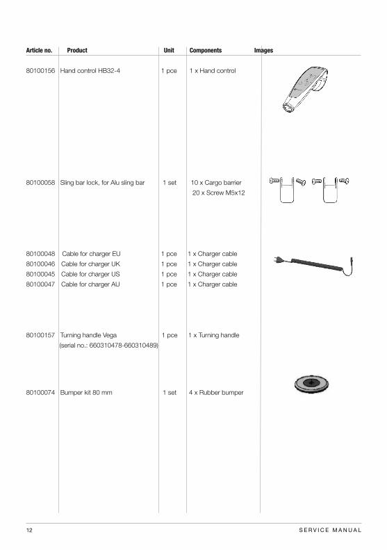
Spare part list
Article no. Product Unit Components Images
80100093 Actuator mast Vega LA44 1 set 1 x Actautor LA44
2 x Locking nut M8
80100056 Actuator base LA23 1 set 1 x Actuator Vega LA23
1 x Motor cable for LA23
2 x Locking nut M8
0,25 x Cardboard
80100001 Front castor 100 mm 1 set 1 x Front castor
1 x Locking nut M10
80100002 Rear castor 100 mm 1 set 1 x Rear castor
1 x Locking nut M10
80100169 Control box CBJC Vega505EE 1 pce 1 x Control box
80100057 Battery CBJ 1 pce 1 x Battery
80100161 Batterybox CBJ BAJ1 1pce 1 x Batterybox
12 S E R V I C E M A N U A L
Article no. Product Unit Components Images
80100156 Hand control HB32-4 1 pce 1 x Hand control
80100058 Sling bar lock, for Alu sling bar 1 set 10 x Cargo barrier
20 x Screw M5x12
80100048 Cable for charger EU 1 pce 1 x Charger cable
80100046 Cable for charger UK 1 pce 1 x Charger cable
80100045 Cable for charger US 1 pce 1 x Charger cable
80100047 Cable for charger AU 1 pce 1 x Charger cable
80100157 Turning handle Vega 1 pce 1 x Turning handle
(serial no.: 660310478-660310489)
80100074 Bumper kit 80 mm 1 set 4 x Rubber bumper

13S E R V I C E M A N U A L
Changing spare parts
80100001, 80100002 Front/rear castor 100 mm
Using an Allen key, remove the screw that holds the castor in place. Replace the castor, apply Loctite 2701 or similar,
and then secure the castor with the screw.
80100045, -46, -47, -48, -52, -59, -60, -61
Connect the charger cable to the control box, and then plug it into a wall socket.
80100051 Control box CBJH
Activate the emergency stop, and then disconnect the actuator and hand control. Remove the two long screws and
remove the control box. Install the new control box and secure it with the two crews. Connect the actuator and control
box.
80100055, 80100056 Actuator leg spreading
Connect the motor cable to the actuator.
Run the actuator until the legs are drawn in fully. Activate emergency stop. Disconnect the actuator from the control box.
Loosen and remove the screw that holds the actuator to the leg. Remove the screw covers and loosen the screw and
nut. Remove the actuator.
Install the new actuator; start by securing the end that is secured to the leg. Use the accompanying lock nut, and then
secure the end that is connected to the base of the mobile lift. Use the accompanying lock nut. Replace the screw
covers. Connect the actuator to the control box.
80100057 Battery CBJ
Remove the lift battery and remove the screws. Disconnect the battery contacts and remove the batteries. Install the
new batteries in the battery box and connect the contacts. Place the cover on the box and secure it with the screws.
Note! The battery must be charged for at least 4 hours before it is used for the first time.
80100058 Slingbar lock for slingbar alu
Remove the screws on either side of the safety latch and remove it. Install the new safety latch and secure it with the two
accompanying M5x12 screws. Position the safety latch, so that the bevelled side is facing in towards the lift hook.
80100062 Hand control 4-button Linak CBJH
Activate the emergency stop, and then disconnect the hand control. Connect the new hand control.
80100065 Front castor 75 mm
80100066 Rear castor 75 mm
Using an Allen key, remove the screw. Replace the castor, securing it with the screw and accompanying lock nut.
80100068 Hanger Strap lock, for steel slingbar
Remove the safety latch by pulling the ring until one side of it is freed from the slingbar, and then remove the other side.
Insert the new safety latch into the hole on one side of the slingbar, and then into the other hole. Ensure that the safety
latch snaps securely into place; it must be able to move freely in the holes.
80100074 Bumper kit
Remove the castors and remove the bumper. Install the new bumper and castors.

14 S E R V I C E M A N U A L
80100074 Bumper kit
Montera loss hjulen och ta bort den gamla bumpern, montera dit den nya tillsammans med hjulet.
80100093 Actuator mast Vega LA44
Sänk lyftarmen till sitt nedersta läge. Aktivera nödstoppen. Koppla ur ställdonet ur kontrollboxen. Montera loss ställ-
donets övre del genom att ta bort täckhattarna och skruva loss skruven och muttern, lossa ställdonets nedre del på
samma sätt. Lyft lyftarmen och tag loss ställdonet. Montera det nya ställdonet. Börja med att passa in den nedre delen,
lyft lyftarmen och passa in den övre delen. Montera fast ställdonet med befintliga skruvar och de nya medföljande lås-
muttrarna. Montera dit täckhattarna och koppla in ställdonet i kontrollboxen.
80100156 Hand control HB32-4
Aktivera nödstoppen och koppla ur handkontrollen, koppla in den nya handkontrollen.
80100157 Turning handle Vega (serial No: 660310478 - 660310489
Använd knopparna för att avlägsna skruvarna. montera de nya skruvarna med knopparna.
80100161 Battery box CBJ Grey BAJ1
Tag loss befintligt batteri genom att lyfta det rakt upp ur hållaren på kontrollboxen. Montera det nya batteriet i hållaren.
Kom ihåg att batteriet måste laddas minst fyra timmar innan första användning.
80100169 Control box CBJC Vega505EE
Aktivera nödstoppen och koppla ur ställdon och handkontroll. Ta bort batteriet, skruva ur de två genomgående
skruvarna och tag bort kontrollboxen. Montera dit den nya kontrollboxen genom att skruva fast den med de två
skruvarna. Sätt tillbaka batteriet och koppla in ställdon och handkontroll igen.

Lift type: Contract no:s/n: Name:Version: Address:Prod. year: Sling bar id.: Situation of use: Home Institution Other
Comments: 1. Attention 2. Correct 3. Do not use!
Periodic inspection - protocol
Date: Load test weight: Serviced by:
In accordance with ISO 10535:2006 Annex B-Periodic inspection
Base:
Check for visible damage
Check:
A Castor
B Brakes
C Screws
Mast:
Inspect the mast
Check:
D Screws
E Lift arm hardware etc
F Link
G Slingbar and the function of the safety latches
H Mast actuator
I Battery and cable installations
J Hand control
K Emergency stop
L Emergency lowering
M Charging
N Product label
Test of safe working load:
Safe working load test mast
Safe working load test base
Mechanical emergency lowering
Accessories:
Documentation:
Instructions / manuals
Controll box:
Reset the control box service counter

16 S E R V I C E M A N U A L
K
J
L
E
L
H
F
G
A
A
N
B
D
C
M
N
I
Description for periodic inspection

17S E R V I C E M A N U A L
Periodic inspection - instruction
Base
-Check the base for visible damage to the surfaces, finish, etc.
Castors
-Roll the lift unloaded on the floor, check that the castors roll and turn freely.
-Check that the castor fasteners are tight.
Brakes
-Lock the brakes. Check that the castors do not turn when the lift is pushed.
Check the legspreading actuator
-Check the legspreading actuator for visible damage to the surfaces, finish, etc.
-Check screws, bolts and links etc.
Mast
-Check the mast for visible damage to the surfaces, finish etc.
-Check screws, nuts, bolts etc.
Screws
-Check screws, and listen for peculiar noises and vibrations.
Liftarm, hardware -Check the liftarm for visible damage to the surfaces, finish etc.
-Check screws, nuts, bolts etc.
Link
-Check the link, slingbar to mast, hardware and covers.
-Check screws, bolts and links etc.
Slingbar and safety latch function
-Check to ensure that there is no visible wear or damage.
- Check the function of the safety latches.
Mast actuator
-Verify that the upper and lower actuator fasteners to the mast are tight.
-Visual inspection.
-Check of abnormal noise level.

18 S E R V I C E M A N U A L
Battery and cable installations
- Check battery and electrical cable.
- Verify that all cables are properly inserted.
Controlbox
-Verify that all functions on the control panel are working
Handcontrol
-Verify that all functions on the handset are working.
Emergency stop
-Verify that the lift does not operate when emergency stop is pressed in.
Emergency lowering
-Verify the function of emergency lowering.
Charging
-Verify that charging is operating. Yellow lamp on the controllbox should light up when charging.
Product label
- Check the serial number so that the label is there and readable. Note the serial number on the protocol.
Test of safe working load
Mast safe working load
-Run the lift with safe working load, all the way up and down, listen for peculiar noises and vibrations.
Base safe working load
-Widen the base with safe working load, listen for peculiar noises and vibrations.
Accessories
-Check the accessories to the lift.
Documentation
- Check that the manual is available and up-to-date.
To reset the service counters press both lift buttons on the hand control at the same time for 5 seconds.
An audio signal will indicate that the timer has been reset.

19S E R V I C E M A N U A L
Maintenance
The lift must undergo thorough inspection at least once per year. Inspection must be performed by authorized personnel
and in accordance with Handicare’s service manual.
Repairs and maintenance may only be done by authorized personnel using original spare parts.
Used batteries are to be left at the nearest recycling station. Used batteries can also be returned to
Handicare or a Handicare dealer for recycling.
Cleaning/disinfection
If necessary, clean the lift with warm water or a soap solution and check that the castors are free from dirt and hair. Do
not use cleaning agents containing phenol or chlorine, as this could damage the aluminium and the plastic materials. If
disinfection is needed, 70 % ethanol, 45 % isopropanol or similar should be used.
Storage and transportation
If the lift is not to be used for some time or e.g., during transport, we recommend that the emergency stop button be
pressed in. The hoist should be transported and stored in -10 ° C to + 50 ° C and in normal humidity, 30% -75 %.
The air pressure should be between 700 and 1060 hPa. Let the hoist reach room temperature before the batteries are
charged or the hoist is used.
Service agreements
Handicare offers the possibility of service agreements for maintenance and regular testing of your mobile lift. Contact
your local Handicare representative.
75%
30%
1060 hPa
700 hPa
+50 °C
-10 °C
75%
30%

20 S E R V I C E M A N U A L
Read user manual
May not be discarded in domestic waste
The product complies with the requirements of the Medical Devices Directive 93/42/EEC.
Type B, according to the degree of protection against electric shock.
The device is intended for indoor use.
Class lI equipment
Always read the user manual
Symbols
Medical Device Class I. The product complies with the requirements of the Medical Devices Directive 93/42/EEC.
Lifting speed: 37 mm/s without load.
Batteries: Two 12V, 2.9 Ah valve-regulated, sealed, lead accumulator (gel-type batteries)
Charger: Max. 400mA
Motor (mast): DC 24V, 9,7 Amp. IP X4. Operationtime: 10% at maximum continous operation of
2 minutes, maximum 5 cycles per minute. Push: 10 000N.
Motor (base): DC 24V, 2.2 Amp. IP X4. Operationtime: 10% at maximum continous operation of
2 minutes, maximum 5 cycles per minute. Push: 1500N.
Sound level: With load: upwards: 43 dB(A) downwards: 44 dB(A).
Material Steel
Emergency lowering: Manual and electrical
Castors: Front 4”, 100 mm, back 4”, 100mm
Weight: 42,8 kg
IP class: IP X4
Expected lifetime: 10 years
Operating forces buttons on
handset:
4 N
Max. load: 230 kg / 505Ibs
Technical Information

21S E R V I C E M A N U A L
Dimensions
230/
9,0
- 17
65/
69.4
668/26.3
250/9.8
685/26.9
637/25
675/26.5
925/36.4
1210/47.6
308/
12.1
67/2
.6
117/
4.6
1235
/48.
6
1998
/78.
6All measurement are in mm/inchTolerance +/- 5 mm/ 0.2”
22 S E R V I C E M A N U A L
1240
1141
490
189
700
1031
350-380
D
F
8
E
D
C
B
A
G
H
J
K
L
M
7654321 9 10 11 12 13 14 15 16
91 2 3 4 5 6 7 8 10 11 12
K
G
A
B
C
D
E
F
H
J
SCALE:1:20
DWG. NO. REV.
NAME DATE
DRAWN
APPROVED BY
SHEET 1 OF 1WEIGHT:
COMMENTS:
STATUS: TITLE
MATERIAL:
SIZE
hc-mabr
Released
Vega EE
60600002 01
g
2010-03-30
A1
Unless otherwise stated, general tolerances according to ISO 2768-m
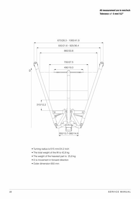
670/26.3 - 1065/41.9
550/21.6 - 925/36.4
860/33.8
700/27.5
490/19.3
310/12.2
350/13.7-380/14.9
• Turning radius is 615 mm/24.2 inch
• The total weight of the lift is 42,8 kg
• The weight of the heaviest part is 25,8 kg
• D is movement in forward direction
• Outer dimension 650 mm
All measurement are in mm/inchTolerance +/- 5 mm/ 0.2”

23S E R V I C E M A N U A L
Tolerance +/- 5 mm/ 0.2”

Handicare AB is quality and environmentcertified in accordance with ISO 9001, ISO 13485 and ISO 14001.
Handicare ABTorshamnsgatan 35 SE-164 40 Kista, SWEDENTel: +46 (0)8-557 62 200 Fax:+46 (0)8-557 62 299 E-mail: [email protected]
More than 30 years in the service of simplicityHandicare’s unique easy transfer concept is the market’s widest
and most complete range of clever, easy-to-use and safe
assistive devices for all types of patient transfers and manual
handling requirements.
The philosophy behind the concept is focused on the prevention
and reduction of occupational injuries while allowing users
to experience a greater sense of independence and dignity.
Through a unique combination of training and a complete range
of efficient transfer aids, we offer improvement of both work environment
and quality of care and, at the same time, achieves
significant cost savings.
Designed and produced by HandicareFor more than 30 years, Handicare has offered simple solutions
for great results, and an easier everyday life for both users and
personnel in the care sector. During 1984-2010 under the
name of RoMedic and, as of January 1, 2011 under the name
of Handicare.
Handicare offers solutions and support to increase the
independence of disabled or elderly people as well as to
improve the convenience of those who are caring for them.
The Handicare Group is one of the leading healthcare companies in
Europe with own manufacturing organizations and sales companies in
Norway, Sweden, Denmark, Germany, the Netherlands, Great Britain,
France, China, Canada and the USA. Handicare’s products are also
distributed by partners in more than 40 countries worldwide.
Our wide range of high-quality products includes a complete easy transfer
system and other patient handling aids, stairlifts, car adaptations
and bathing and toileting products.