vehicle and personnel collision warning systems for … and perso… · · 2012-10-29vehicle and...
TRANSCRIPT

0
Vehicle and Personnel Collision Warning Systems for Open Pit and Underground 15 May 2008
Steven Niven
Anglo Coal Regional Engineering Services
1
August 2006: Formation of an Anglo American Collision Avoidance working group from all business units. Base metals, Platinum, Iron Ore, Tarmac & Coal.
Objective: To identify and investigate various technologies currently available, and in development to prevent accidents and incidents between haul trucks and light vehicles, and vehicles and personnel, for both open pit and underground operations, and produce a report on recommended technologies.
November 2006: Anglo Coal Vehicle Management Safety Committee.
Objective:To look at all aspects of vehicle management, road conditions and construction, vehicle management planning, operator training, fatigue, signage, safety devices
Introduction

2
Open Pit Operations
3
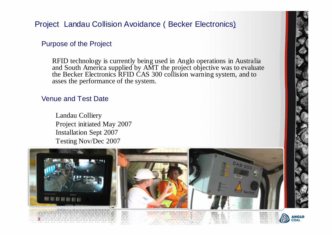
Purpose of the Project
RFID technology is currently being used in Anglo operations in Australia and South America supplied by AMT the project objective was to evaluate the Becker Electronics RFID CAS 300 collision warning system, and to asses the performance of the system.
Venue and Test Date
Landau Colliery Project initiated May 2007Installation Sept 2007Testing Nov/Dec 2007
Project Landau Collision Avoidance ( Becker Electronics)
4
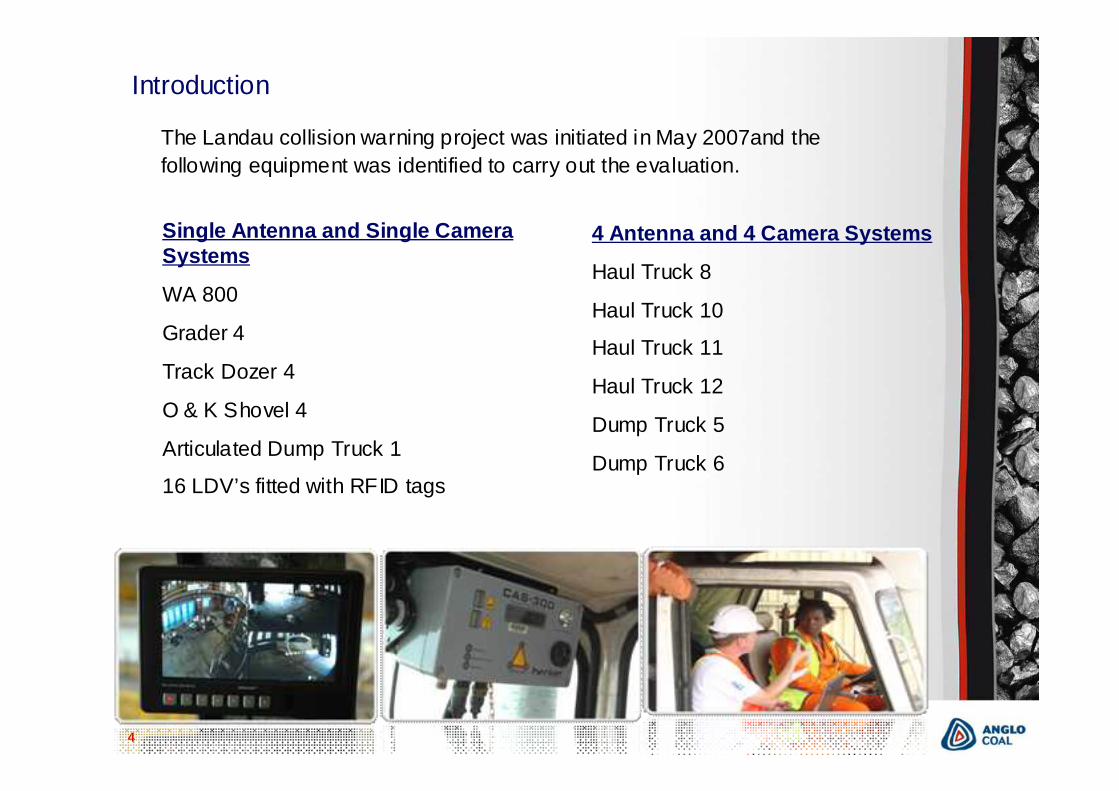
Introduction
The Landau collision warning project was initiated in May 2007and the following equipment was identified to carry out the evaluation.
Single Antenna and Single Camera Systems
WA 800
Grader 4
Track Dozer 4
O & K Shovel 4
Articulated Dump Truck 1
16 LDV’s fitted with RFID tags
4 Antenna and 4 Camera Systems
Haul Truck 8
Haul Truck 10
Haul Truck 11
Haul Truck 12
Dump Truck 5
Dump Truck 6
5
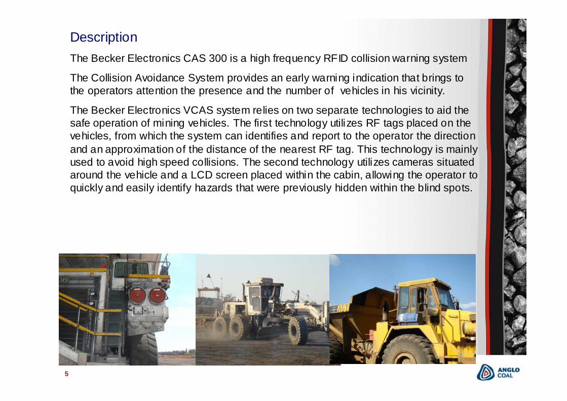
DescriptionThe Becker Electronics CAS 300 is a high frequency RFID collision warning system
The Collision Avoidance System provides an early warning indication that brings to the operators attention the presence and the number of vehicles in his vicinity.
The Becker Electronics VCAS system relies on two separate technologies to aid the safe operation of mining vehicles. The first technology utilizes RF tags placed on the vehicles, from which the system can identifies and report to the operator the direction and an approximation of the distance of the nearest RF tag. This technology is mainly used to avoid high speed collisions. The second technology utilizes cameras situated around the vehicle and a LCD screen placed within the cabin, allowing the operator to quickly and easily identify hazards that were previously hidden within the blind spots.
6
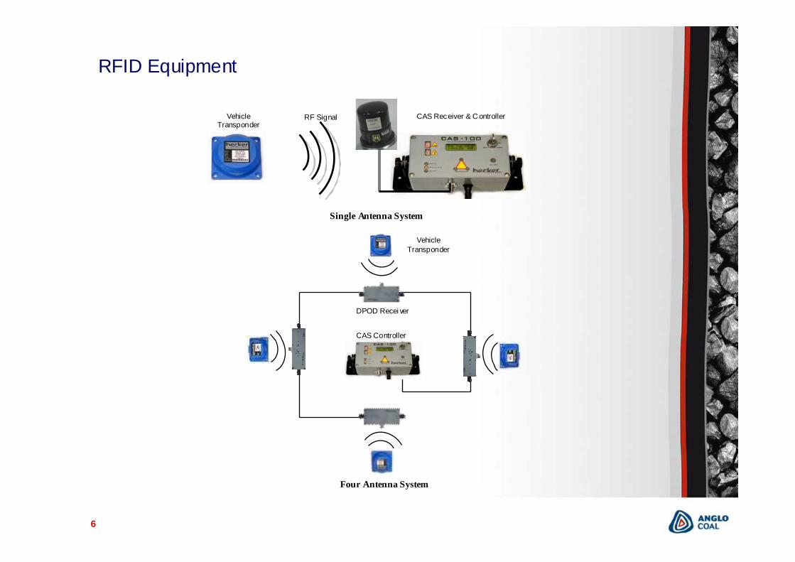
RFID Equipment
CAS Controller
DPOD Recei ver
Vehicle Transponder
Single Antenna System
Four Antenna System
VehicleTransponder
CAS Receiver & C ontrollerRF Signal
7
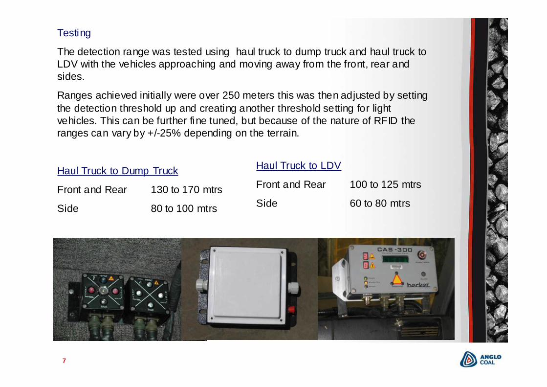
Testing
The detection range was tested using haul truck to dump truck and haul truck to LDV with the vehicles approaching and moving away from the front, rear and sides.
Ranges achieved initially were over 250 meters this was then adjusted by setting the detection threshold up and creating another threshold setting for light vehicles. This can be further fine tuned, but because of the nature of RFID the ranges can vary by +/-25% depending on the terrain.
Haul Truck to Dump Truck
Front and Rear 130 to 170 mtrs
Side 80 to 100 mtrs
Haul Truck to LDV
Front and Rear 100 to 125 mtrs
Side 60 to 80 mtrs
8
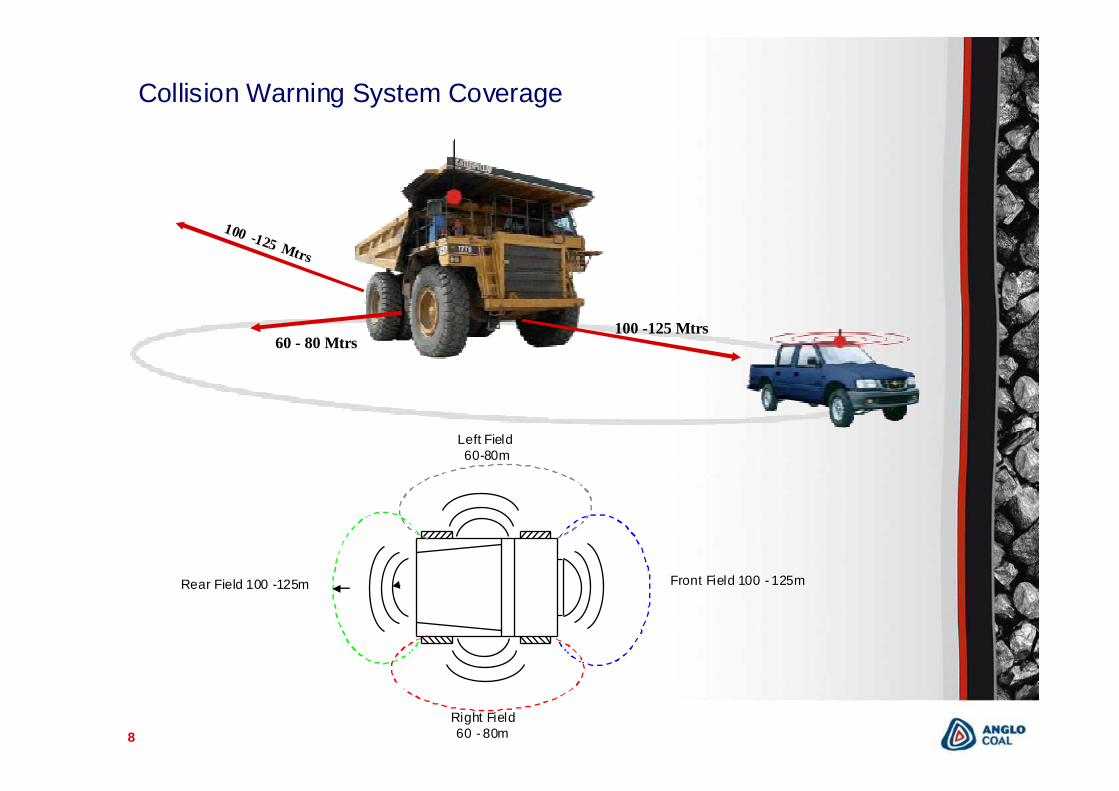
Collision Warning System Coverage
100 -125 Mtrs60 - 80 Mtrs
Front Field 100 - 125m
Right Field 60 - 80m
Left Field60-80m
Rear Field 100 -125m
100 -125 Mtrs
9
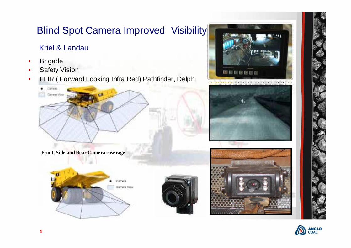
Blind Spot Camera Improved Visibility
Front, Side and Rear Camera coverage
• Brigade• Safety Vision• FLIR ( Forward Looking Infra Red) Pathfinder, Delphi
Kriel & Landau
10
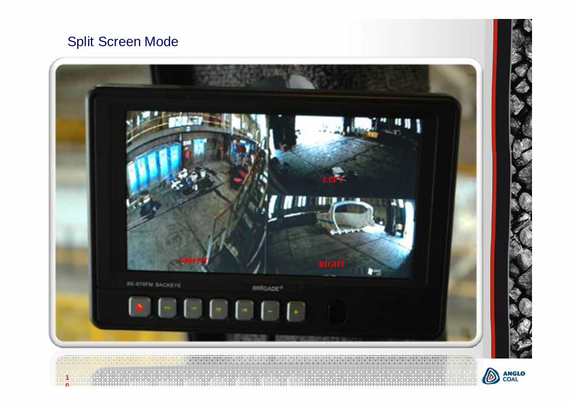
Camera View Split Screen
FRONT RIGHT
LEFT
Split Screen Mode
11
Kriel Tip to Pit FLIR Camera
12
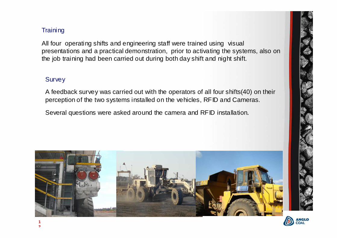
Training
All four operating shifts and engineering staff were trained using visual presentations and a practical demonstration, prior to activating the systems, also on the job training had been carried out during both day shift and night shift.
Survey
A feedback survey was carried out with the operators of all four shifts(40) on their perception of the two systems installed on the vehicles, RFID and Cameras.
Several questions were asked around the camera and RFID installation.
13
Camera Issues
Problems identifying cameras – Text was put onto screen identifying cameras.
3 way split screen confusing – The monitors have had their software modified to accommodate requested changes on future screens.
Monitor too bright at night causing too much glare – auto adjust and brightness settings.
Cameras not clear at night – recommend installing additional infra red lights for left, right and reverse camera and using cameras with 18 IR led s built around lens.
RFID Issues
Number of alarm coming through to the operator
Using I button to learn all vehicles when in hard park
Unable to positively identify which vehicles are being detected
Fluctuations in detection ranges
14
Concerns
Detection range varies by as much as 20% depending on terrain
Every time the system detects a tag on another vehicle it sounds the buzzer, this leads to complacency and the operator gets used to the alarm going off.
The operators find it difficult to determine which vehicle are being detected
Vehicle identified on the perimeter of the detection range tend to come and go on the CAS unit causing nuisance alarms.
Cluster display not bright enough during the day (Becker are addressing this in next version)
The system alarms when the vehicle is stationary.
As more vehicles have RFID equipment installed the number of alarms will increase.
Equipment has a large foot print in cabin
15
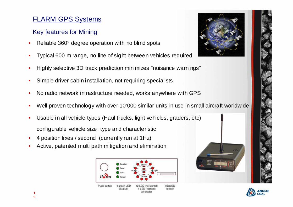
• Reliable 360° degree operation with no blind spots
• Typical 600 m range, no line of sight between vehicles required
• Highly selective 3D track prediction minimizes "nuisance warnings"
• Simple driver cabin installation, not requiring specialists
• No radio network infrastructure needed, works anywhere with GPS
• Well proven technology with over 10’000 similar units in use in small aircraft worldwide
• Usable in all vehicle types (Haul trucks, light vehicles, graders, etc)
configurable vehicle size, type and characteristic• 4 position fixes / second (currently run at 1Hz)• Active, patented multi path mitigation and elimination
Key features for Mining
FLARM GPS Systems
16
17
18
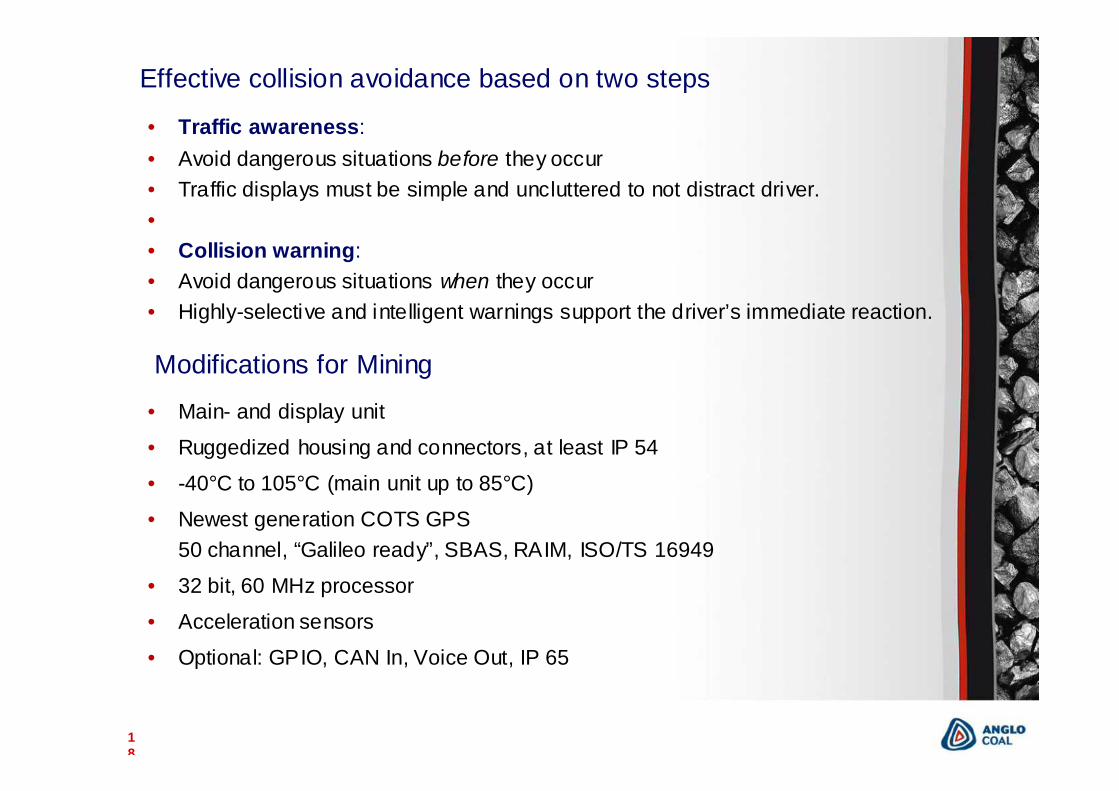
Effective collision avoidance based on two steps
• Traffic awareness:• Avoid dangerous situations before they occur• Traffic displays must be simple and uncluttered to not distract driver.•• Collision warning: • Avoid dangerous situations when they occur• Highly-selective and intelligent warnings support the driver’s immediate reaction.
• Main- and display unit
• Ruggedized housing and connectors, at least IP 54
• -40°C to 105°C (main unit up to 85°C)
• Newest generation COTS GPS50 channel, “Galileo ready”, SBAS, RAIM, ISO/TS 16949
• 32 bit, 60 MHz processor
• Acceleration sensors
• Optional: GPIO, CAN In, Voice Out, IP 65
Modifications for Mining
19
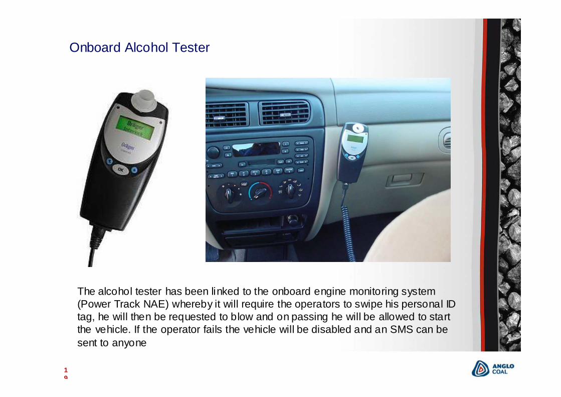
Onboard Alcohol Tester
The alcohol tester has been linked to the onboard engine monitoring system (Power Track NAE) whereby it will require the operators to swipe his personal ID tag, he will then be requested to blow and on passing he will be allowed to start the vehicle. If the operator fails the vehicle will be disabled and an SMS can be sent to anyone
20
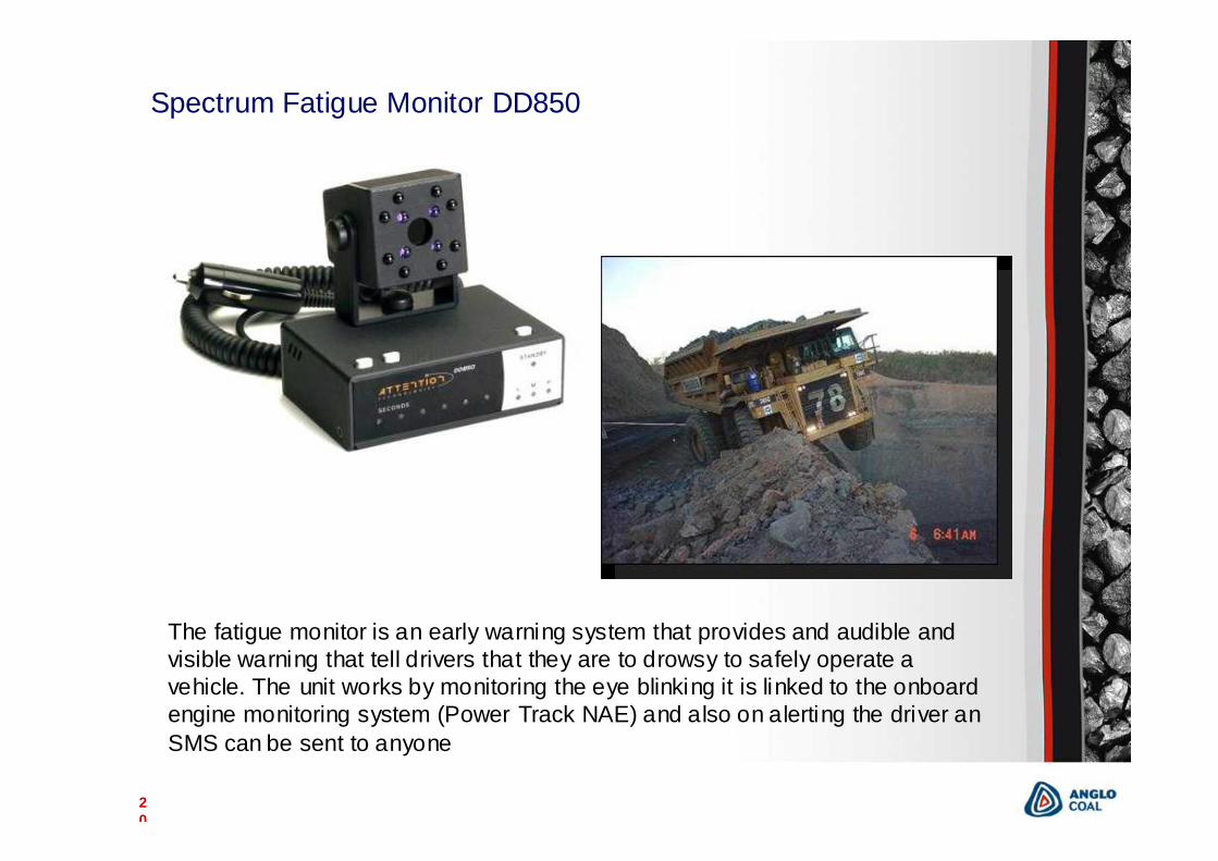
Spectrum Fatigue Monitor DD850
The fatigue monitor is an early warning system that provides and audible and visible warning that tell drivers that they are to drowsy to safely operate a vehicle. The unit works by monitoring the eye blinking it is linked to the onboard engine monitoring system (Power Track NAE) and also on alerting the driver an SMS can be sent to anyone
21
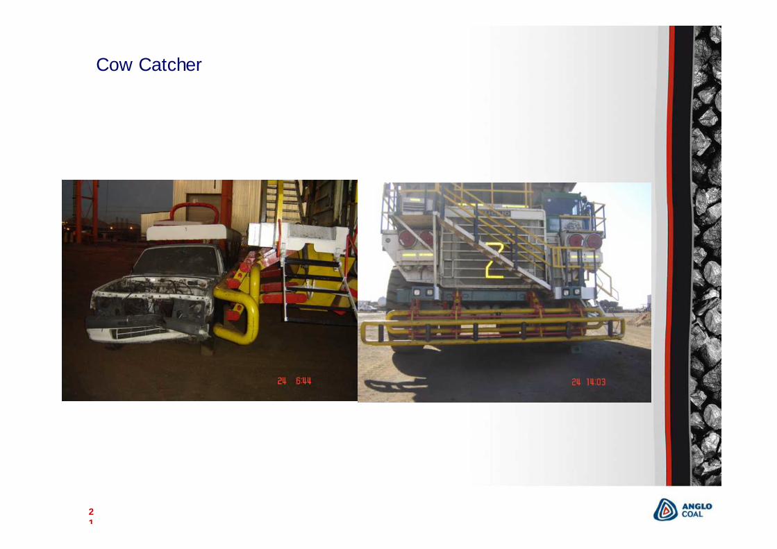
Cow Catcher
22
Surface Collision Warning
Anglo Coal Underground Collision Warning System
Road Map

23
Anglo Coal Underground Collision Warning System Road Map
24
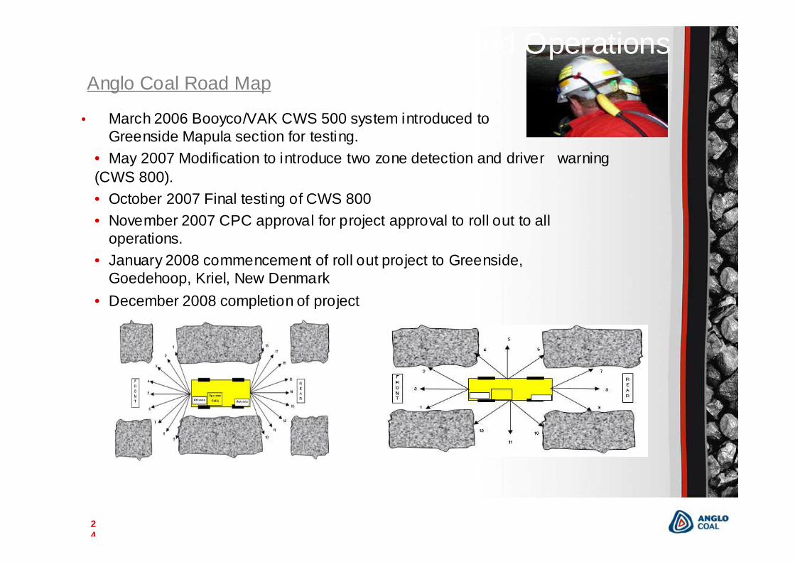
• March 2006 Booyco/VAK CWS 500 system introduced to Greenside Mapula section for testing.
• May 2007 Modification to introduce two zone detection and driver warning (CWS 800). • October 2007 Final testing of CWS 800• November 2007 CPC approval for project approval to roll out to all
operations.• January 2008 commencement of roll out project to Greenside,
Goedehoop, Kriel, New Denmark• December 2008 completion of project
Collision Warning Underground OperationsAnglo Coal Road Map
25
Collision Warning Underground Operations
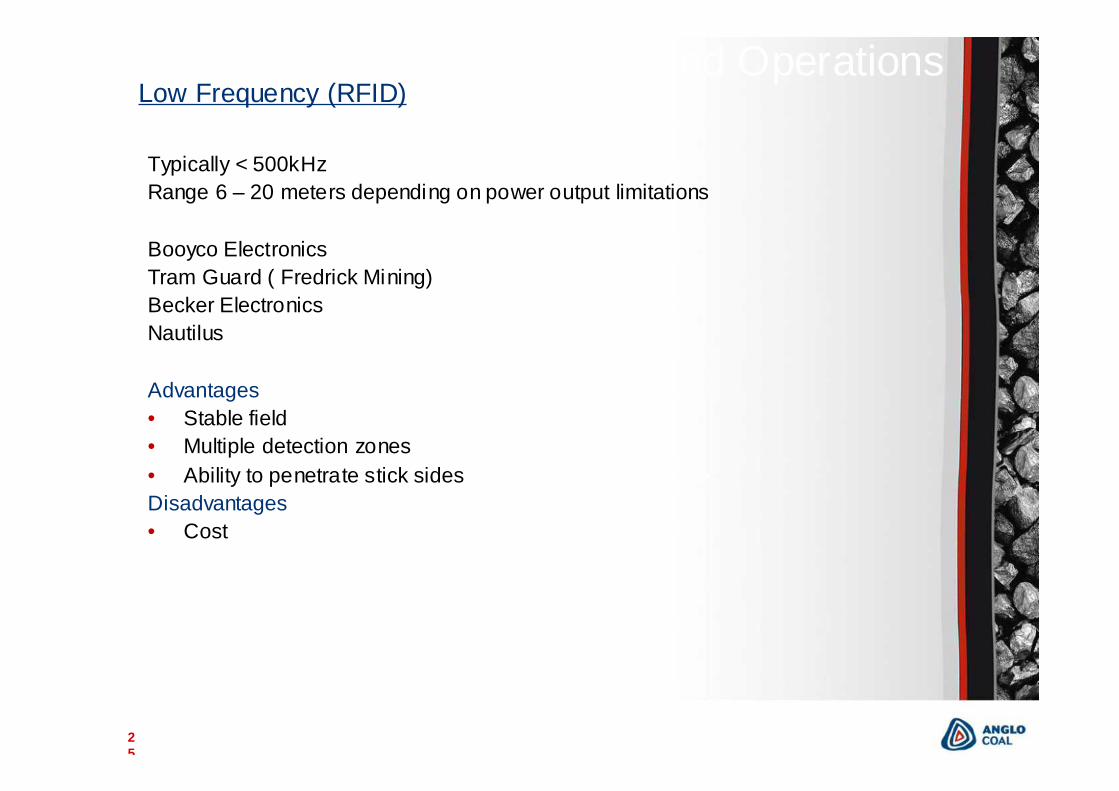
Typically < 500kHzRange 6 – 20 meters depending on power output limitations
Booyco ElectronicsTram Guard ( Fredrick Mining)Becker Electronics Nautilus
Advantages• Stable field• Multiple detection zones• Ability to penetrate stick sidesDisadvantages• Cost
Low Frequency (RFID)
26
Low Frequency (RFID)
• Currently the only viable solution for collision warning on underground vehicles is Low Frequency
• The Low Frequency collision warning systems typically utilize a combination of low and high Frequency RFID (radio frequency identification) to detect the presence of a person within a predefined warning or alarm zone of an approaching vehicle.
• The person is identified via a tag built into his battery pack or using a personal alarm device (PAD)
• The Low frequency antenna or field generator creates an Electro magnetic field around the vehicle . The high frequency system is used to transmit an alarm back to the vehicle when a person enters the warning or alarm area.
• The system warns the miner of the approaching vehicle depending on the preference, by sounding a buzzer, flashing his cap lamp, or illuminating flashing LEDs built into an inline unit or cap lamp battery cover, and when the person goes into the danger zone a signal is transmitted to the vehicle to alerts the driver.
27
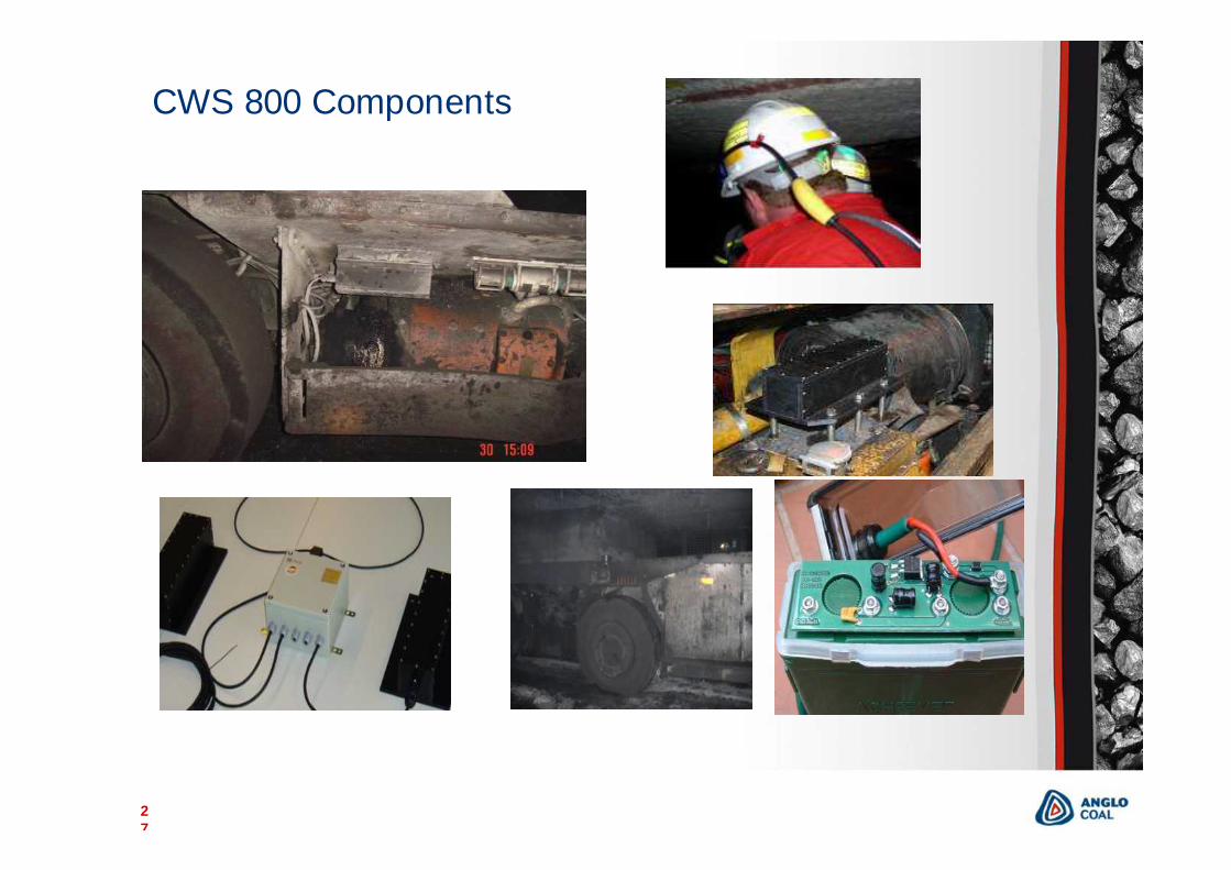
CWS 800 ComponentsCWS 800 Components

28
Antennas installed on drivers side
Antennas installed on opposite side
Plotting of fields around Vehicle
Antennas installed diagonally opposite
29
The development of a Last Line of Support (LLOS) warning device had been undertaken in November 2006, as there was no commercially available equipment.
Several different technologies were initially tested with some success but there were limitation for these technologies in the underground environment. (Infrared, Ultrasonic)
A decision was made to adapt the Underground Personnel Warning System technology (Low Frequecy RFID) to suit this application. The prototype has been completed and will be sent to Kriel in April 2008 for testing and evaluation.
Challenges for this device are, to limit the power consumption so that the device can be powered from standard cap lamp batteries, with a four day life before being changed, ExIa certification, and to produce a narrow detection field .
2nd Last Line of Support Warning Device
30
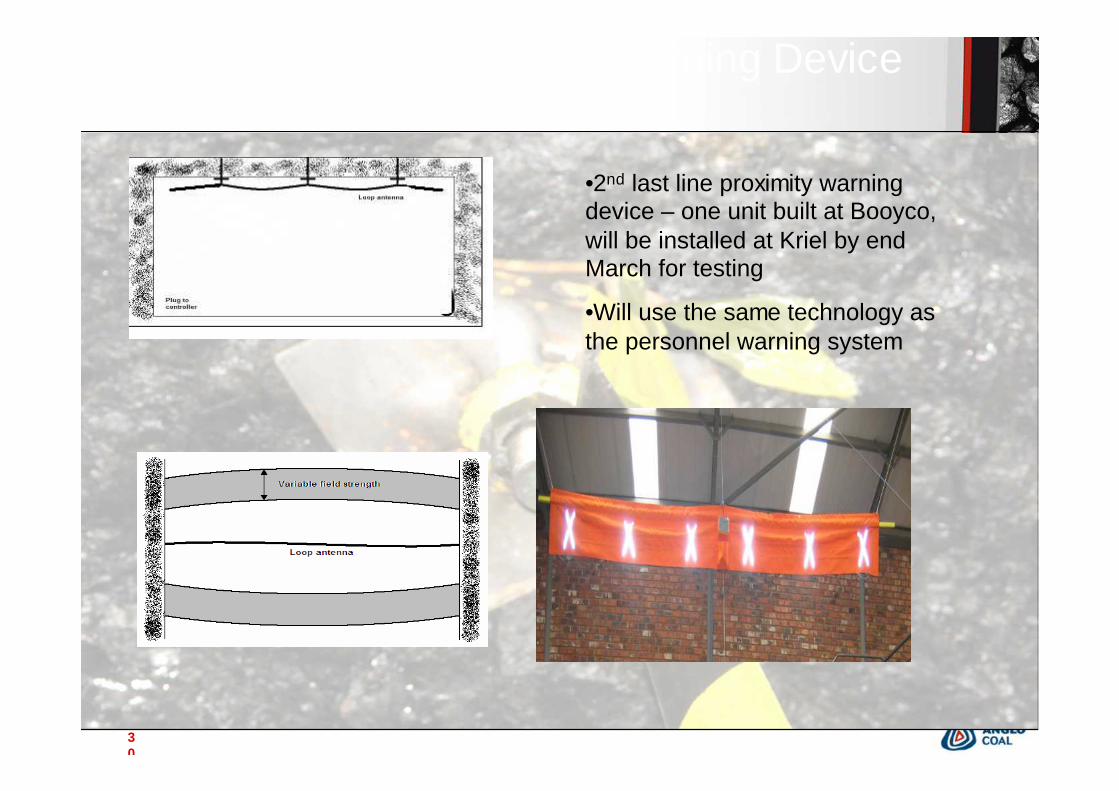
•2nd last line proximity warning device – one unit built at Booyco, will be installed at Kriel by end March for testing
•Will use the same technology as the personnel warning system
2nd Last Line of Support warning Device

31
Thank you!