vehicle spy 3 - cdn.intrepidcs.net · i i i i 10 4 2016 i 2016 i i i i version history version...
TRANSCRIPT

Intrepid Control Systems, Inc.31601 Research Park Drive Madison Heights, MI 48071 USA(ph) +1-586-731-7950 (fax) +1-586-731-2274www.intrepidcs.com www.aeta-rice.com
Vehicle Spy 3Multipurpose Vehicle Network Tool
Vehicle Spy Quick Start GuidesUsing Vehicle Spy with Ethernet
Version 1.0 - February 4, 2016

Vehicle Spy Quick Start Guides
i © 2016 Intrepid Control Systems, Inc.Version 1.0 - February 4, 2016
Using Vehicle Spy with Ethernet
Version History
Version Number Date Description / Major Changes
1.0 2016/02/04 Initial release.
Vehicle Spy Quick Start Guides
i © 2016 Intrepid Control Systems, Inc.Version 1.0 - February 4, 2016
Using Vehicle Spy with Ethernet
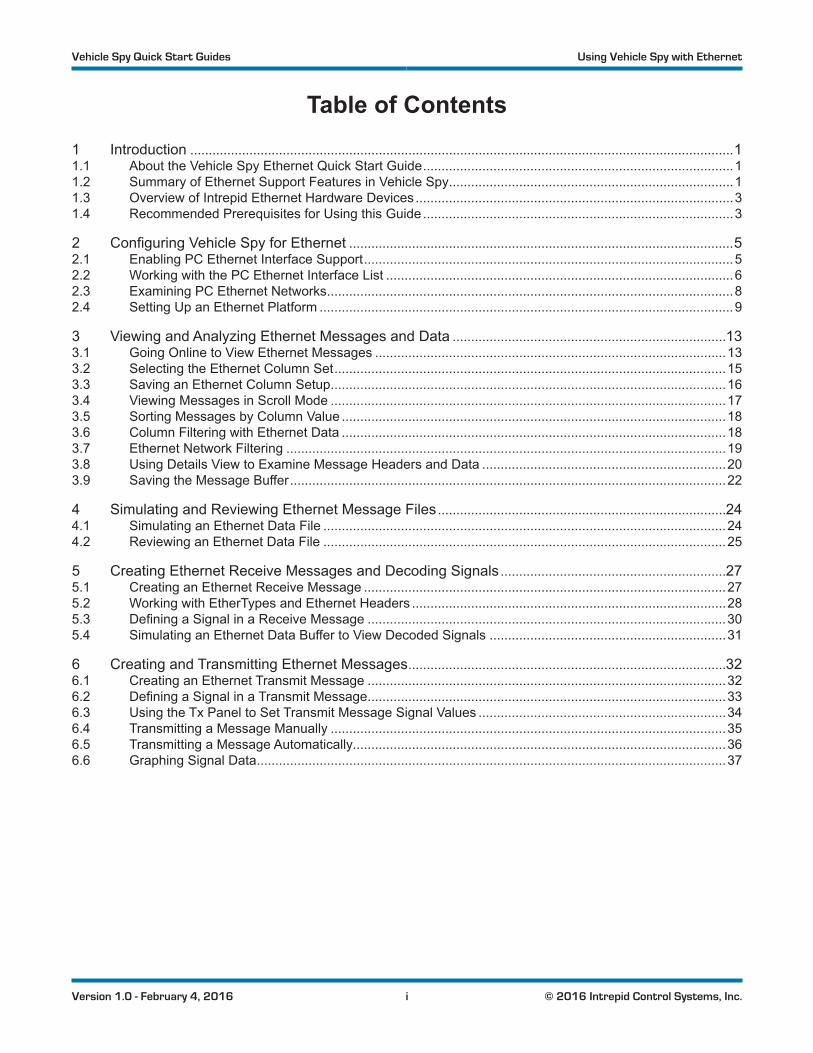
Table of Contents1 Introduction ...................................................................................................................................................11.1 About the Vehicle Spy Ethernet Quick Start Guide ....................................................................................11.2 Summary of Ethernet Support Features in Vehicle Spy .............................................................................11.3 Overview of Intrepid Ethernet Hardware Devices ......................................................................................31.4 Recommended Prerequisites for Using this Guide ....................................................................................3
2 ConfiguringVehicleSpyforEthernet ........................................................................................................52.1 Enabling PC Ethernet Interface Support ....................................................................................................52.2 Working with the PC Ethernet Interface List ..............................................................................................62.3 Examining PC Ethernet Networks ..............................................................................................................82.4 Setting Up an Ethernet Platform ................................................................................................................9
3 Viewing and Analyzing Ethernet Messages and Data ..........................................................................133.1 Going Online to View Ethernet Messages ...............................................................................................133.2 Selecting the Ethernet Column Set ..........................................................................................................153.3 Saving an Ethernet Column Setup ...........................................................................................................163.4 Viewing Messages in Scroll Mode ...........................................................................................................173.5 Sorting Messages by Column Value ........................................................................................................183.6 Column Filtering with Ethernet Data ........................................................................................................183.7 Ethernet Network Filtering .......................................................................................................................193.8 Using Details View to Examine Message Headers and Data ..................................................................203.9 Saving the Message Buffer ......................................................................................................................22
4 Simulating and Reviewing Ethernet Message Files ..............................................................................244.1 Simulating an Ethernet Data File .............................................................................................................244.2 Reviewing an Ethernet Data File .............................................................................................................25
5 Creating Ethernet Receive Messages and Decoding Signals .............................................................275.1 Creating an Ethernet Receive Message ..................................................................................................275.2 Working with EtherTypes and Ethernet Headers .....................................................................................285.3 DefiningaSignalinaReceiveMessage .................................................................................................305.4 Simulating an Ethernet Data Buffer to View Decoded Signals ................................................................31
6 Creating and Transmitting Ethernet Messages ......................................................................................326.1 Creating an Ethernet Transmit Message .................................................................................................326.2 DefiningaSignalinaTransmitMessage .................................................................................................336.3 Using the Tx Panel to Set Transmit Message Signal Values ...................................................................346.4 Transmitting a Message Manually ...........................................................................................................356.5 Transmitting a Message Automatically.....................................................................................................366.6 Graphing Signal Data ...............................................................................................................................37

Vehicle Spy Quick Start Guides
1 © 2016 Intrepid Control Systems, Inc.Version 1.0 - February 4, 2016
Using Vehicle Spy with Ethernet
1 IntroductionWelcome to Using Vehicle Spy with Ethernet, one of the quick start guides for Intrepid’s powerful Vehicle Spy (VSpy) network analysis and diagnostics software. In this guide you will learn about the new VSpy features implemented to support working with Automotive Ethernet, andgo“handson”toperformbasictaskssuchasviewingEthernettraffic,decodingEthernetsignal data, and creating and transmitting Ethernet messages.
1.1 About the Vehicle Spy Ethernet Quick Start Guide
The purpose of this guide is to help you quickly get up to speed in using Vehicle Spy with Automotive Ethernet messages and hardware. The guide contains the following six chapters:
1. Introduction: You’re reading it!
2. Configuring Vehicle Spy for Ethernet: Explains how to set up Vehicle Spy to use an Ethernet interface and work with Intrepid Ethernet hardware and databases.
3. Viewing and Analyzing Ethernet Messages and Data: Shows you how to go online to viewEthernettrafficonadatabase,andhowbesttoworkwithEthernetmessagesanddata within Messages View.
4. Simulating and Reviewing Ethernet Message Files: Demonstrates how to simulate savedEthernetdataforanalysispurposes,orsimplyreviewthecontentsofafile.
5. Receiving Ethernet Messages and Decoding Signals: Walks you through creating an Ethernet receive message in the Messages Editor,includingdefiningasignal,andthensimulating a buffer to view decoded data.
6. Creating and Transmitting Ethernet Messages: Takes you through the process of defininganexampleEthernetmessagewithasignal,settingthesignalvalue,andtransmitting the message both manually and automatically.
Most people learn more readily by doing than reading. Accordingly, this is an interactive guide that uses examples with step-by-step instructions that you can do on your own computer as you follow along. Many screenshots are provided to help you understand exactly what is happening. Action items, meaning steps where you need to actively do something, are set apartfromtherestofthetextforgreatervisibilityusingaright-facingpointercharacter(“►”).
1.2 Summary of Ethernet Support Features in Vehicle Spy
Interest in Automotive Ethernet has grown rapidly over the last few years, and Intrepid Control Systemshaspositioneditselfasaleaderinthefield.Ifyouarenewtothetechnology,youmay wish to pick up a copy of Intrepid’s book, Automotive Ethernet - The Definitive Guide (Figure 1). This 1,100+ page reference provides a thorough description of Automotive Ethernet, as well as a comprehensive description of TCP/IP protocols.

Vehicle Spy Quick Start Guides
2 © 2016 Intrepid Control Systems, Inc.Version 1.0 - February 4, 2016
Using Vehicle Spy with Ethernet
Figure 1: Automotive Ethernet - The Definitive Guide. Intrepid’s industry-leading book will help you understand Automotive Ethernet.
Over the last two years, Intrepid has worked hard to implement support for Automotive EthernetnetworkswithinitsflagshipVehicleSpyproduct.Herearejustsomeofthekeyfeatures that have been added:
• Logon screen shows Ethernet interfaces and allows one to be selected to work with.
• Support for displaying Ethernet messages in Messages View.
• Built-in, independent TCP/IP stack with ability to easily set and change IP address and other parameters.
• Support for TCP/IP and AVB message types (UDP, TCP, ARP, PTP, etc.)
• CustomcolumnsetsandfiltersforEthernet,TCP,FSAandPTP.
• Messages EditorcangenerateEthernetmessageswithpre-configuredheadersforIP,TCP, UDP, ICMP and other protocols.
• AutomaticdefaultsettingsloadedforTCP/IPandAVBprotocolheaderfields.
• Ethernet packet template editor allows customization of default settings for protocol headers.
• Support for Intrepid hardware tools (see Section 1.3).
• SupportforthestandardEthernetPCAPdriverandloadingandsaving.PCAPfiles.
• Support for GM-only FSA view and databases, and transmitting/receiving FSA data.
• Details View shows Ethernet messages broken down by layer and protocol with individual signals decoded for TCP/IP, AVB and PTP protocols.

Vehicle Spy Quick Start Guides
3 © 2016 Intrepid Control Systems, Inc.Version 1.0 - February 4, 2016
Using Vehicle Spy with Ethernet
• BytehighlightingbasedonselectedprotocolandfieldwithinDetails View.
• Supportfor.VSB(VehicleSpybinary)filesforEthernetframes,includingsavingerrorframes that are not supported in .PCAP format.
• Support for native MAC address and IP address notation in Messages Editor, Tx Panel and Application Signals.
1.3 Overview of Intrepid Ethernet Hardware Devices
Intrepid Control Systems offers a growing array of network tools to assist you in the development of your Automotive Ethernet network:
• RAD-Moon: A simple media converter that allows a BroadR-Reach (100BASE-T1) device to be connected to a conventional Ethernet network.
• RAD-Star: An active tap that allows messages between two BroadR-Reach devices to be monitored and sent to a PC, and messages also to be sent to BroadR devices from the PC.
• RAD-Galaxy: A set of six active taps with a high-speed Gigabit Ethernet connection and many additional features.
• Ethernet Evaluation Board (EEVB): A special board with two complete BroadR-Reach nodes and a Lab Manual with more than 20 hands-on experiments to help you quickly become an Automotive Ethernet expert.
• neoVI FIRE 2: Intrepid’s latest-generation general network interface device includes Ethernet and Diagnostics over IP (DoIP) support.
In addition, Intrepid’s neoVI ION and neoVI PLASMA products support Automotive Ethernet dataloggingwhenusedinconjunctionwithaRAD-GalaxyorRAD-Star.
For more information on Intrepid hardware products, please contact Intrepid Control Systems or visit our website at http://intrepidcs.com.
1.4 Recommended Prerequisites for Using this Guide
Due to the large number of features in Vehicle Spy, complete coverage of the program is beyond the scope of this document. We recommend that you be familiar with basic Vehicle Spy operationsbeforecontinuing,suchashowtostartVSpy,navigatemenus,goonline/offline,and switch among VSpy window. Experience with Messages View and the Messages Editor is also recommended. If you are new to Vehicle Spy, you may wish to attend one of Intrepid’s Vehicle Spy Basics training courses, which are offered both in-person and online.
You can use Vehicle Spy Ethernet features either with the Intrepid Ethernet hardware tools discussed in Section 1.3, or simply by monitoring a wired or wireless network interface in a

Vehicle Spy Quick Start Guides
4 © 2016 Intrepid Control Systems, Inc.Version 1.0 - February 4, 2016
Using Vehicle Spy with Ethernet
PC. However, in order to take Vehicle Spy online, you will need an Intrepid hardware device with a hardware license. This can be any of the Intrepid Ethernet hardware tools discussed in Section 1.3, except for the RAD-Star or RAD-Moon (which do not use a hardware license). If you have only a RAD-Star or RAD-Moon, you can use any other Intrepid device, such as a ValueCAN or neoVI FIRE / FIRE 2, to activate VSpy.
Figure 2showsanexampleofwhatVehicleSpymaylooklikewhenyoufirstlaunchitwithanEthernet EVB properly installed. Notice the picture of the device near the bottom of the screen, and its two nodes listed along with their serial numbers and node letter designations (“A” and “B”).
Figure 2: Vehicle Spy Logon Screen with Ethernet EVB Device Installed.
Vehicle Spy Quick Start Guides
5 © 2016 Intrepid Control Systems, Inc.Version 1.0 - February 4, 2016
Using Vehicle Spy with Ethernet
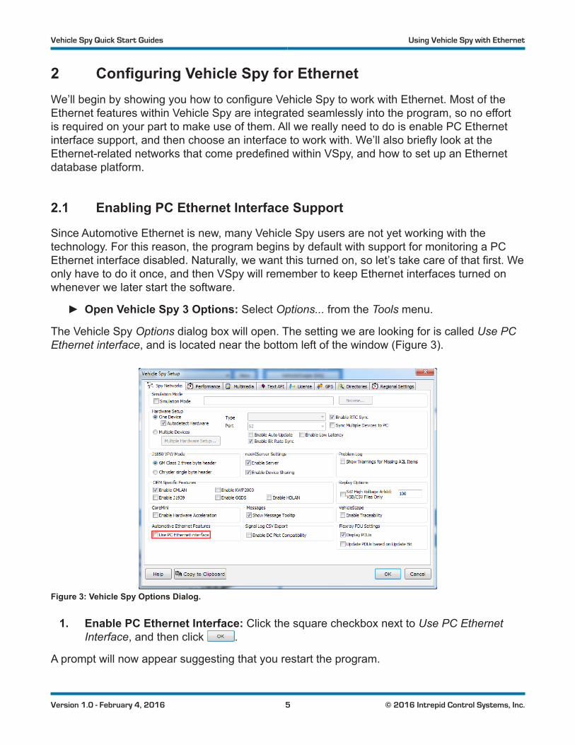
2 Configuring Vehicle Spy for EthernetWe’llbeginbyshowingyouhowtoconfigureVehicleSpytoworkwithEthernet.MostoftheEthernet features within Vehicle Spy are integrated seamlessly into the program, so no effort is required on your part to make use of them. All we really need to do is enable PC Ethernet interfacesupport,andthenchooseaninterfacetoworkwith.We’llalsobrieflylookattheEthernet-relatednetworksthatcomepredefinedwithinVSpy,andhowtosetupanEthernetdatabase platform.
2.1 Enabling PC Ethernet Interface Support
Since Automotive Ethernet is new, many Vehicle Spy users are not yet working with the technology. For this reason, the program begins by default with support for monitoring a PC Ethernetinterfacedisabled.Naturally,wewantthisturnedon,solet’stakecareofthatfirst.Weonly have to do it once, and then VSpy will remember to keep Ethernet interfaces turned on whenever we later start the software.
► Open Vehicle Spy 3 Options: Select Options... from the Tools menu.
The Vehicle Spy Options dialog box will open. The setting we are looking for is called Use PC Ethernet interface, and is located near the bottom left of the window (Figure 3).
Figure 3: Vehicle Spy Options Dialog.
1. Enable PC Ethernet Interface: Click the square checkbox next to Use PC Ethernet Interface, and then click .
A prompt will now appear suggesting that you restart the program.

Vehicle Spy Quick Start Guides
6 © 2016 Intrepid Control Systems, Inc.Version 1.0 - February 4, 2016
Using Vehicle Spy with Ethernet
2. Restart Vehicle Spy 3: Click and Vehicle Spy will close. (If you are prompted to save changes, select “No”.) Start the program again from the Windows start menu or desktop.
When the program loads again you will now see a list of Ethernet interfaces at the bottom right of the screen, as shown in Figure 4. In this case we have three interfaces shown. Due to the small window size we use to keep screenshots legible, the names are shortened and hard to read, but we’ll show you in a moment how to get around that.
Figure 4: Vehicle Spy Logon Screen with PC Ethernet Interfaces Enabled.
2.2 Working with the PC Ethernet Interface List
With PC Ethernet interface support now enabled, we have a list of Ethernet interfaces in the bottom right of the Vehicle Spy Logon Screen. However, Figure 4 uses a relatively small window size. You can see more of the interface list by enlarging the window, or by dragging to the left the vertical slider that divides the hardware device list and Ethernet interface list. You can also do both, as we did to create Figure 5.

Vehicle Spy Quick Start Guides
7 © 2016 Intrepid Control Systems, Inc.Version 1.0 - February 4, 2016
Using Vehicle Spy with Ethernet
Figure 5: Resized Hardware Device and Ethernet Interface Lists.
After resizing, we can see that this computer currently has three interfaces: a wireless (“Wi-Fi”) network adapter, the Ethernet EVB, and the PC’s wired Ethernet adapter. Note that from Vehicle Spy’s perspective, all of wired Ethernet, Wi-Fi and Bluetooth are considered Ethernet interfaces and will show up here.
Selecting an Ethernet Interface
The radio buttons are used to select which interface you want Vehicle Spy to use; here the Ethernet EVB has been selected by default. We are going to start working with Ethernet by lookingatliveInternettrafficinChapter 3, so let’s select the interface that the PC is using for its Internet connection. On the PC used for this guide, that’s the wired Ethernet interface; select whichever one is appropriate for your machine.
► Select the Interface Used by the PC to Connect to the Internet: Click the radio button to the left of the appropriate interface. In our example, it would be the one that says Local Area Connection (the last one, on the bottom).
Viewing Ethernet Interface Statistics
Notice the two columns on the left side of the Ethernet interface list. The Packets/s column shows approximately how many messages are being received on the interface each second, while Total counts all messages seen by Vehicle Spy 3, either since it was started, or since the list was refreshed.
YoucanusethesecolumnstomonitoroveralltrafficonthePC’sEthernetinterfaces.Thiscanbe handy in certain cases. For example, if we weren’t sure whether the PC was connected to the Internet over its wired or wireless interface, the data here would tell us pretty quickly which one is actually active.
Refreshing Ethernet Interfaces
The button can be used for two purposes. First, it tells Vehicle Spy to update the interface list, adding any new network connections that have been added since the program was started, and removing any that have been disabled. Second, it can be used to reset the statistics in the two columns.
► Refresh the Ethernet Interfaces List: Click .

Vehicle Spy Quick Start Guides
8 © 2016 Intrepid Control Systems, Inc.Version 1.0 - February 4, 2016
Using Vehicle Spy with Ethernet
Your list of interfaces should remain the same, but notice that the packet counts of all interfaces are reset to zero, and then the active ones begin counting up again.
2.3 Examining PC Ethernet Networks
VehicleSpycomespre-configuredwithanumberofdifferentcommonly-usedautomotivenetworks. This now includes Automotive Ethernet and related networks. You can view VSpy networks and manage their parameters in the Networks setup area.
► View Vehicle Spy Networks: Select Networks from the Spy Networks menu.
Since Ethernet is relatively new, most of its relevant information is found near the bottom of the network list.
► Scroll to the Bottom of the Network List.
You should now see a display similar to that seen in Figure 6.
Figure 6: Vehicle Spy Network List with Ethernet and Related Networks Highlighted.
The networks relevant to Ethernet are:

Vehicle Spy Quick Start Guides
9 © 2016 Intrepid Control Systems, Inc.Version 1.0 - February 4, 2016
Using Vehicle Spy with Ethernet
• Ethernet: This is the “main” Ethernet interface. The Network column will show the interface last used when Vehicle Spy went online.
• Ethernet DAQ (neoVI 3G):UsedtoreceivedEthernettrafficfromsupportedIntrepidhardware devices such as the neoVI PLASMA and neoVI ION.
• FSA: A virtual network to support GM’s FSA technology.
• TCP: A virtual network that displays logical data carried in TCP messages on the Ethernet network.
• OP (BR) ETHn:These12networkscarryindividualtrafficstreamsfromthetapinputson the RAD-Galaxy.
Note that you normally won’t need to change any of the defaults in this area when working with Ethernet.
2.4 Setting Up an Ethernet Platform
AplatformisacollectionofdatabasefilesthatisloadedwithinVehicleSpytoprovideinformation about messages. A platform can be used to create transmit messages that send data in a particular format, or receive messages that decode data read in from the network.
Platforms are important for many Automotive Ethernet applications, so we’ll now spent a bit of timelearningaboutthem,andhowtosetthemupspecificallyforEthernet.Inparticular,we’llseehowtocreateaplatformfromanAUTOSARdatabasefile.
Selecting a Platform
The current platform is always displayed in a drop-down box at the top of Vehicle Spy. To change the current platform, simply select the one you want from the box; VSpy will automatically load its associated databases. Choosing the default platform, “(None)”, will unload all databases. The two buttons to the right of the drop-down box are used to set up databases for a platform, and to save pending platform changes, respectively.
Figure 7: Platform Drop-Down Box with Platform Database Setup and Platform Save Buttons.
Creating a New Platform
Let’s make a new platform that we can use for working with Ethernet.
► Launch Platform Setup: Select Setup Platforms from the Setup menu. A dialog box appears to allow you to work with platforms. Figure 8 shows how this dialog box appears before any platforms have been created.

Vehicle Spy Quick Start Guides
10 © 2016 Intrepid Control Systems, Inc.Version 1.0 - February 4, 2016
Using Vehicle Spy with Ethernet
Figure 8: Platform Setup Dialog Box.
► Add Ethernet Platform: Click the button; another dialog box appears. Enter the name “Ethernet” and press Enter. Click to exit platform setup.
Vehicle Spy will create your new Ethernet platform, and also set the current platform to “Ethernet”; you should see this in the drop-down box on top of VSpy now.
Adding an ARXML Database File to the Ethernet Platform
We have our platform created but it is currently empty, so we will now want to add a database to it. Vehicle Spy offers many ways of doing this, but we will focus on doing this via an AUTOSARdatabasefile,whichusesthe.ARXMLformat.Forthisdemonstration,weareusingacustomexamplefile;youshouldhaveyourowndatabasefileyoucansubstituteintheinstructions below.
► Enter Network Database Setup: Select Network Databases from the Setup menu, or click the button next to the platform selection drop-down box.
The Network Databases view opens, with a list of networks on the left, and tabs along the top corresponding to different methods of adding databases.
► Go to the ARXML Area: Click the ARXML / UEF / VSDB Support tab.
► Assign an ARXML File to the Platform: Click .
The ARXML Import dialog box appears (Figure 9)toallowyoutoselectARXMLfilesandassociate clusters with VSpy networks.

Vehicle Spy Quick Start Guides
11 © 2016 Intrepid Control Systems, Inc.Version 1.0 - February 4, 2016
Using Vehicle Spy with Ethernet
Figure 9: ARXML Import Dialog Box.
► Add ARXML File: Click ,navigatetothefoldercontainingyour.ARXMLfile,andselectit.Thefileweareusingiscalled“ethernet_sample.arxml”;yourswillprobablyhave a different name.
VehicleSpywillshowthenameofthefileinthefilelistinthetophalfofthescreen,andlisttheclusters it references in the cluster/network list in the bottom half.
► Assign Network(s) to ARXML Cluster(s): Double-click in the cell under Vehicle Spy Network for the clusters that were loaded, and choose which networks you want to associatewitheach.Inourexamplewehavejustonecluster,called“EtherSample”,which we’ll link to the Ethernet network (Figure 10).
Figure 10: ARXML Import Dialog Box Showing Assignment of Ethernet Network to ARXML Cluster.

Vehicle Spy Quick Start Guides
12 © 2016 Intrepid Control Systems, Inc.Version 1.0 - February 4, 2016
Using Vehicle Spy with Ethernet
► Finish ARXML Import: After making the appropriate network assignments, press the button.
VehicleSpywillnowloadthedatabaseinthe.ARXMLfileandpromptyoutosavethechangesyou have made to your platform (quite visibly, to ensure you don’t lose your work!)
► Save Database Changes:Presseitheroftheflashingbuttonstosavethechangestoyour platform.
Your platform is now set up.
Viewing Platform Database Messages
Platform database messages appear within the database area of the Messages Editor, where they can be copied to quickly make transmit or receive messages. Let’s take a look.
► Open Messages Editor: Select Messages Editor from the Spy Networks menu.
► Select Ethernet Network: Click the drop-down box next to the words on Network in the blueheader,scrolldownuntilyoufindthe“Ethernet”entry,thenselectit.
► Select Database Messages: Press the button.
You should now see a set of database messages that you can use with your Ethernet network. Exactly what appears here will, of course, depend on the contents of the database you loaded. Figure 11 shows a few example messages from our sample database.
Figure 11: Sample Ethernet Database Messages.

Vehicle Spy Quick Start Guides
13 © 2016 Intrepid Control Systems, Inc.Version 1.0 - February 4, 2016
Using Vehicle Spy with Ethernet
3 Viewing and Analyzing Ethernet Messages and DataNow that we have Vehicle Spy properly set up, we are ready to begin working with Ethernet messages and data. In this chapter we’ll learn how to go online to view “real world” Ethernet / TCP/IP messages from the Internet, and see how to work with them effectively within VSpy’s Messages View. This will include tailoring the display of messages for Ethernet, seeing how to sortandfilterEthernetmessages,usingDetails View to look at the data within messages, and learning how to save Ethernet data for later analysis.
This chapter assumes that you have followed the instructions in Chapter 2 to enable PC Ethernet interfaces, and have chosen the interface that your PC uses to connect to the Internet.
3.1 Going Online to View Ethernet Messages
Support for displaying Ethernet messages is built into Vehicle Spy, so to start looking at Ethernet messages, we simply need to go online.
► Go Online: Press the button located near the top left of the Logon Screen. You can also press the buttonfoundjustbelowit(thesecanbeseennearthetopleftofFigure 4).
Vehicle Spy 3 will automatically switch to Messages View and begin displaying the Ethernet trafficfoundontheselectedinterface.Ifforsomereasontheviewdoesnotchange,simplyselect Messages from the Spy Networks menu. Note that if you have previously been simulatingafileinVehicleSpy,youmayneedtoclickthedrop-downboxnexttothe button and explicitly choose Run with Transmit.
You should see a display similar to Figure 12. Notice that the button has changed to the (Stop) button at the top left, and the word Online appears next to it, showing that we are online. Messages View begins by default in static mode, which groups together similar messages to make it easier to monitor the network as a whole. In the case of Ethernet, messages are grouped based on their source and destination addresses, as well as the message type (EtherType).

Vehicle Spy Quick Start Guides
14 © 2016 Intrepid Control Systems, Inc.Version 1.0 - February 4, 2016
Using Vehicle Spy with Ethernet
Figure 12: Initial Messages View Display with Ethernet Messages.
You may see some TCP entries in the display; there is one at the bottom of the displayed messagelistinthefigure.ThesearelogicaldisplaysofTCPdatacarriedwithinEthernetmessages. To make it easier to see more message types, we can suppress the display of this inline data in Messages View:
► Disable Display of Inline TCP Data: Near the top of Messages View,findthecheckboxnext to the word Expand. Click the box to clear the checkmark from it.
TCP messages will now collapse down so they take up less space. Later on we’ll see how we canusenetworkfilterstoisolateorsuppressnetworktypes.
Fornow,let’sgooffline.
► Go Offline: Press the buttontogooffline.

Vehicle Spy Quick Start Guides
15 © 2016 Intrepid Control Systems, Inc.Version 1.0 - February 4, 2016
Using Vehicle Spy with Ethernet
3.2 Selecting the Ethernet Column Set
By default, Vehicle Spy begins with the Messages View in its generic display format, which is designedtosupportmanytypesofvehiclenetworks.SincewearespecificallyinterestedinEthernet, we will change the display to one that provides more information relevant to Ethernet messages.
► Change the Messages View Columns Display to Ethernet: Near the bottom of the Messages View you should see the word Columns, and to the right, a drop-down box in which “(default)” is currently selected. Click the box, scroll down, and change the setting to “Ethernet” (Figure 13).
Figure 13: Selecting the Ethernet Column Display. This setting will cause Messages View to display information pertinent to work with Automotive Ethernet.
The information in the Messages ViewwillimmediatelychangetomoreEthernet-specificdataDepending on the size of your display, you may or may not see all of the columns available; youmayalsofindthatsomearetoonarrowtoseealloftheircontents.EnlargethewindowandadjustthecolumnsuntilyoucanseeallthecolumnsuptoLen (short for “Length”). You should see something similar to Figure 14.
The Count, Time, Tx, Er and Len columns are used in the same way as they are with more conventionalnetworkssuchasCAN.HereisabriefexplanationoftheEthernet-specificcolumns:
• Description: For Ethernet messages these summaries begin with “Ethernet” and then generally contain the source and destination addresses. These will be either MAC addresses for plain Ethernet or AVB frames, or IP addresses for TCP/IP messages.
• Source and Destination: The sender and receiver of the message, which again will be either MAC addresses or IP addresses.
• Src Port and Dst Port: The source and destination port numbers for UDP and TCP messages.
• EtherType: The interpreted value of the two-byte EtherType fieldintheEthernetheader,indicating the type of data being carried in the frame. Typical values are “IPv4”, “IPv6” or “ARP”.

Vehicle Spy Quick Start Guides
16 © 2016 Intrepid Control Systems, Inc.Version 1.0 - February 4, 2016
Using Vehicle Spy with Ethernet
• Protocol: The interpreted value of the IPv4 Protocol fieldorIPv6Next Header field,specifying the higher-level protocol message being carried in an IPv4/IPv6 message. This will normally be either “UDP” or “TCP”, or blank for non-IP messages.
Figure 14: Messages View After Selecting Ethernet Columns and Adjusting Column Sizes. We can now see several new columnsspecifictoEthernetmessages:Source, Src Port, Destination, Dst Port, EtherType, Protocol and VLAN.
3.3 Saving an Ethernet Column Setup
Ethernet setups in Vehicle Spy can be saved for later use in exactly the same way you would do when working with other networks. In this case, since we have now tailored the Messages View to look good when working with Ethernet messages, we’ll save the setup. Then we can reload it at any time in the future when we want to work with Ethernet.
► Create a New Setup File: Select Save As from the File menu. When the dialog box appears, enter “Ethernet Column Setup”.
That’s it. Your setup is now saved, and the next time you load it Messages View will immediately be ready for working with Ethernet.

Vehicle Spy Quick Start Guides
17 © 2016 Intrepid Control Systems, Inc.Version 1.0 - February 4, 2016
Using Vehicle Spy with Ethernet
3.4 Viewing Messages in Scroll Mode
We mentioned earlier that Vehicle Spy defaults to aggregating similar messages for easier tracking and analysis. However, when working with Ethernet it is often useful to see messages sequentially rather than having them grouped in this manner. Naturally, we can easily change between the two modes.
► Go Online: Press .
► Enable Scroll Mode: Press the button, located near the top left of Messages View.
You will immediately see the change in the message display, as it (appropriately enough) begins scrolling, each new message appearing in a separate line rather than being grouped (Figure 15). Notice also that the Count column has now been replaced by a Line column, the number of which increases sequentially.
Figure 15: Messages View After Enabling Scroll Mode.
EthernettrafficcancomeintoVehicleSpyquickly,soyoumayfindithelpfultomakeuseofthe button to temporarily halt the message scrolling when in this mode.
Nowlet’sgobacktostaticmodeandgoofflineagain.
► Enable Static Mode: Press again to turn off scroll mode.

Vehicle Spy Quick Start Guides
18 © 2016 Intrepid Control Systems, Inc.Version 1.0 - February 4, 2016
Using Vehicle Spy with Ethernet
Vehicle Spy 3 resumes showing you messages statically aggregated by type with counts.
► Go Offline.
3.5 Sorting Messages by Column Value
Ethernet messages in Messages View can be sorted by clicking on column headers in exactly the same way as you might do with other networks. Let’s try an example.
► Sort by Source Column: Click on the Source column.
All of the messages in the buffer will now be sorted based on their source IP address or MAC address; you should see something similar to Figure 16. As always, you can choose from ascending order ( symbol shows in the column) or descending order ( symbol). Of course, you can also sort using the standard columns, such as Count or Len.
Figure 16: Messages View with Ethernet Data Sorted by Source Address. This is the top of the buffer, showing messages with the lowest-numbered Source addresses captured in this session: 23.92.109.10.
Let’s now remove the sorting:
► Remove Sort: Click the Source column two more times to return to the default view.
3.6 Column Filtering with Ethernet Data
Filtering using columns is a quick and easy way of isolating groups of messages from what can beaverylargebufferofEthernetdata.SimplyenterthefiltercriteriaintotheFilter bar as you would when working with CAN or another network. As always, you can use question marks and asterisks as wildcards, hyphens for ranges, and commas to create lists of values.
Asanexample,supposewewanttofindalloftheDomainNameSystem(DNS)messagessent by our PC. These requests are used to resolve names like “www.intrepidcs.com” into IP addresses. DNS requests are sent to the connected Internet provider’s server on destination port 53.

Vehicle Spy Quick Start Guides
19 © 2016 Intrepid Control Systems, Inc.Version 1.0 - February 4, 2016
Using Vehicle Spy with Ethernet
► Filter for Outgoing DNS Messages: Enter “53” into the Filter bar cell under the Dst Port column.
The message display will now change to show only the messages we are interested in; an example can be seen in Figure 17.
Figure 17: Messages View with Active Column Filter.
Let’snowremovethefilter.
► Clear DNS Filter: Remove the “53” from the Dst Portfiltercell.
Messages View will return to showing all messages.
3.7 Ethernet Network Filtering
Sometimes you may be working with a mixed network containing Ethernet, CAN, LIN and possibly other types of messages. In addition, as we’ve already seen, some Ethernet messages actually generate two lines in Messages View: one for the basic Ethernet message, and one for the virtual TCP network. If FSA is in use, these messages too will show up with both Ethernet and FSA entries.
Toviewtrafficfromspecificnetworks,usethenetworkfiltercolumnsontheleftsideofMessages View. The left-most column with the checkmark at the top is used to include networksyouwanttosee,andthecentercolumnwiththe“X”excludesnetworksyoudonotwant.(Theright-mostcolumnisforcustomfilters,whichwewon’tbecoveringinthisguide.)
For example, suppose we want to see only the logical TCP messages on the network, and not the underlying Ethernet messages that carry them.
► Include the TCP Network: Click the box in the left-hand column for the TCP network. A checkmark appears.
► Exclude the Ethernet Network: Click the box in the center column for the Ethernet network.An“X”appears.
Figure 18showswhatthefilterareashouldlooklike.Afterenteringthesefilters,youshouldsee only TCP messages in the message display area of Messages View. (You may need to click the mouse in the messages area for it to update.)

Vehicle Spy Quick Start Guides
20 © 2016 Intrepid Control Systems, Inc.Version 1.0 - February 4, 2016
Using Vehicle Spy with Ethernet
Figure 18: Filters to Show TCP Messages and Exclude Ethernet Messages.
Note that, as always is the case in Vehicle Spy, if you want to exclude a network, you must include at least one network explicitly or nothing will be shown.
► Remove the TCP Network Inclusion: Click the checkmark next to the TCP network to remove it.
Since no network is now included, you should now see the messages area go completely blank (again, you may need to click in the messages area to see this).
► Remove the Ethernet Network Exclusion:Clickthe“X”nexttotheEthernetnetwork.
Messages from all networks are now displayed again.
3.8 Using Details View to Examine Message Headers and Data
The blue rectangular area at the bottom of Messages View is sometimes called Details View or the Details Pane,andallowsyoutodigintothefieldsinanymessagetoletyouseewhat’s really going on in your network. It’s an especially powerful tool for Automotive Ethernet because you can use it to examine each of the layers of headers and data found in complex encapsulated messages such as those used in TCP/IP.
You should see Details View open, unless it was previously disabled in a prior use of VSpy on your machine. If you don’t see it, press the button to enable it.
The Details View window contains three panes. The information pane on the left shows a list of messages and decoded information about them; for Ethernet messages, you will see here a list of the headers in the message. On the right is a byte/character display of the selected message. In the center, you’ll see an area with Name and Value columns that are used to display the values of decoded messages. The contents of all of these panes will change depending on the type of message is selected in the Messages View. The relative sizes of the three panes can be changed by dragging the vertical dividers between them.
Asanexample,let’strylookingataTCP/IPUDPmessage.Wecanfindoneeasilybyusingafilter.
► Filter for UDP Messages: Enter “UDP” in the Protocol filtercell.
Nowjustclickanyofthesemessages.
► Select a UDP Message: Click any UDP message currently shown in Messages View.
You should now see details for the message shown in Details View, like the example in Figure 19.

Vehicle Spy Quick Start Guides
21 © 2016 Intrepid Control Systems, Inc.Version 1.0 - February 4, 2016
Using Vehicle Spy with Ethernet
Figure 19: Details View for a UDP Message.
Asyoucansee,therearefourlinesintheleft-handpane.Thefirstisthegeneralinformationline for an Ethernet message. The next three show the nested headers for a UDP message: Ethernet, Internet Protocol and User Datagram Protocol.
If you select one of these lines, the corresponding header bytes in the message will be highlighted in the data area on the right.
► Select the Internet Protocol Header: Click the Internet Protocol Version 4 header in the information pane.
You should see 20 bytes highlighted in gray in the byte area, corresponding to the 20 bytes in a standard IPv4 header (Figure 20).
Figure 20: Details View Display for a UDP Message with IP Header Highlighted. Here we have the Details View display for a typical UDP message. When the IPv4 header is selected in the information pane, Vehicle Spy 3 highlights its 20 bytes in the byte/character display area.
Notice that each header has a “+” button to its left. We can use these to “drill down” into the headerstolookatthefieldstheycontain.
► Expand the UDP Header: Click the UDP header in the Details View information pane, and then click the button to the left of it.
Vehicle Spy now highlights the UDP data bytes in gray (right-hand pane), and shows you the valuesofthefieldswithintheUDPheaderinthismessage(left-handpane).Anexampleisshown in Figure 21.

Vehicle Spy Quick Start Guides
22 © 2016 Intrepid Control Systems, Inc.Version 1.0 - February 4, 2016
Using Vehicle Spy with Ethernet
Figure 21: UDP Message Details View with Expanded Ethernet Header. The same UDP message shown in Figure 20, butwiththeUDPheaderselectedandexpandedtoshowitsfields.Noticethechangetothehighlightinginthebyte/characterdisplay area.
Youcanalsohighlightspecificfieldsintheheaderstofindexactlywheretheyarelocatedinthe bytestream of the message.
► Highlight the Source Port Field: Click the Source Port fieldundertheUDPheader.
Youwillnowseejusttwobyteshighlightedingrayontheright,sincethisfieldis16bitslong(Figure 22).
Figure 22: UDP Message Details View with Source Port Field Selected.Notethatthevalueofthefieldis53(decimal)corresponding to the byte value 35 (hexadecimal) in the byte/character display.
3.9 Saving the Message Buffer
Afteryoucapturesomeimportantdatafromyournetwork,youcaneasilysaveittoafileforlater analysis.
► Click the Save Button: Click the button near the top of Messages View.
You will be prompted with an options dialog box like the one in Figure 23.

Vehicle Spy Quick Start Guides
23 © 2016 Intrepid Control Systems, Inc.Version 1.0 - February 4, 2016
Using Vehicle Spy with Ethernet
Figure 23: Save Buffer Data Dialog Box.
In most cases the defaults here are what you want: the .VSB format is ideal for Ethernet messages. Having Append date and time to custom file name checkedwillmakeiteasytofindsaved buffers, and ensure that later buffer saves don’t overwrite newer ones.
NotethatEthernetdatacanalsobestoredin.PCAPfiles(whicharecompatiblewithotherTCP/IP network analysis tools) but not in VSpy’s traditional .CSV format.
► Save the Buffer: Click the button.
The buffer will be stored in your current data directory.
► Open the Data Directory: Click the button located near the top right of Vehicle Spy.
VSpy will launch Windows Explorer set to the location of your data directory. Sort the list by Date Modified and you should see your buffer at the top.
Oneimportantnote:besuretoclearnetworkfiltersthatexcludeunderlyingEthernetmessages—like the one we used in Section 3.7—before saving the buffer. If you include a virtual network like TCP or FSA, but exclude Ethernet, then no messages will be saved.

Vehicle Spy Quick Start Guides
24 © 2016 Intrepid Control Systems, Inc.Version 1.0 - February 4, 2016
Using Vehicle Spy with Ethernet
4 Simulating and Reviewing Ethernet Message FilesOnceyouhavesavedEthernetdatatoafile,youhaveseveraloptionsforworkingwithit.Twoof the most important are simulating thefileandreviewing it, which we’ll show you how to do in this chapter.
Note that this part of the guide assumes that you saved a buffer of Ethernet data in Section 3.9. If you have not done this yet, please review the relevant parts of Chapter 3 and save an Ethernet buffer before proceeding here.
4.1 Simulating an Ethernet Data File
Simulatingadatafileisanalternativetogoingonlinewithalivenetwork.VehicleSpywillreplaythefile,causingitsmessagestoappearinMessages View in the same order, and with the same timing, as occurred on the network when they were captured. This is a useful tool for diagnosing problems, since you can repeat a message exchange in the same way multiple times. You can also control the speed of the simulation, slowing it down for easier observation.
Ifyou’vesimulatedafileinVehicleSpybefore,theprocessisprettymuchthesameforEthernetdatafiles.
► Browse to Data Directory: Click the down-arrow next to the button, hover the mouse over Run Simulation, and when the submenu appears, select Browse... (Figure 24).
Figure 24: Browsing to a Simulation File.
AWindowsfileselectionboxwillnowappearopenedonyourdatadirectory.
► Select a Simulation File:Clickthefileyouwanttosimulate(probablytheoneyousaved earlier in the guide), then click the button.
Assumingthatavalidfilewasselected,VehicleSpywillbeginplayingbackitsmessageswithin Messages View. The screen will appear quite similar to how it did when going online live, except that you will notice the simulation bar at the top, which shows you VSpy’s progress asitgoesthroughthefile(Figure 25). The current speed of the simulation is shown in the bar (inthefigureitsays“speed:1.00x”).Youcanchangethisbymovingtheadjacentspeedsliderleft or right, selecting a speed from 0.01x to 20x.

Vehicle Spy Quick Start Guides
25 © 2016 Intrepid Control Systems, Inc.Version 1.0 - February 4, 2016
Using Vehicle Spy with Ethernet
Figure 25: Simulating an Ethernet Data File.
Bydefault,thesimulationwillcontinuouslyloopthroughthefile.Youcanturnthisoffbyclickingthe button.
Youstopthesimulationbygoingoffline.
► Go Offline: Press the button.
4.2 Reviewing an Ethernet Data File
Reviewingafileisusedmostoftentosimplylookatwhatmessagesitcontains.Youchoosethefileandthemessagesareshownintheordertheywerestoredwiththesametimestamps.Again, this process is pretty much the same for Ethernet data as it is for other networks.
Let’s try an example.
► Tell Vehicle Spy to Review a File: Choose Review Buffer... from the File menu.
► Select a File:WhentheWindowsfileselectiondialogappears,selectafilefromyourdata directory.
Vehicle Spy will now present a dialog box allowing you to choose what platform you want touseandwhetheryouwanttoloadthefileinstandardorstreamingmode.Again,thisis

Vehicle Spy Quick Start Guides
26 © 2016 Intrepid Control Systems, Inc.Version 1.0 - February 4, 2016
Using Vehicle Spy with Ethernet
identicaltowhathappenswhenreviewinga.VSBfilewithCANorothernetworkdata.Inmostcases we can leave these options at their default settings.
► Proceed with File Review: Click the button.
VehicleSpywillloadthebufferfile,stoppingwiththelastmessageshowedatthebottomoftheMessages View display.

Vehicle Spy Quick Start Guides
27 © 2016 Intrepid Control Systems, Inc.Version 1.0 - February 4, 2016
Using Vehicle Spy with Ethernet
5 Creating Ethernet Receive Messages and Decoding SignalsIn the preceding chapters we have learned how to view and work with live Ethernet messages on an Internet connection. You can work with your automotive network in exactly the same way,goingonlineandmonitoringnetworktraffic.WhenworkingwithactualECUsandotherEthernet nodes, however, you will often want to create Vehicle Spy receive messages that describe particular message types and provide information for VSpy to decode their contents.
This can be accomplished with Ethernet messages in a manner similar to how you have traditionally worked with CAN and other network data. However, due to the complexity of many Automotive Ethernet message formats, Intrepid has added special capabilities to make working with Ethernet messages more user-friendly.
Inthischapterwe’llseehowtodefineanEthernetreceivemessage,addasignaltoit,andthendecodeEthernetdatausingthemessagedefinition.Wehavecreatedaspecialdatabuffer of Ethernet messages and put it on our website to assist with this demonstration. Before proceeding,pleasedownloadthefilefromthefollowinglocation,andstoreitinyourdatadirectoryoranywhereelseonyourPC:http://www.intrepidcs.com/ae/ethernet_data.vsb
5.1 Creating an Ethernet Receive Message
We’llbeginbydefiningabasicEthernetreceivemessage.Again,theprocessisverysimilarto doing this for a CAN message, so assuming you have some VSpy experience, much of the following should be familiar.
Let’s clear out anything that may already be present within Vehicle Spy, and then go to the Messages Editor.
► Reset Vehicle Spy to Start Configuration: Select New from the File menu.
► Open Messages Editor: Select Messages Editor from the Spy Networks menu.
Since we want to work with Ethernet, we will change the default in the on Network drop-down box from the default of “HS CAN” to “Ethernet”.
► Select Ethernet Network: Click the drop-down box in the blue header and scroll down untilyoufindthe“Ethernet”entry,thenselectit.
We should already be on the “receive side” of the Messages Editor, as indicated by the blue highlighting on the button. If for some reason it is not blue, press this button to select receive messages.
Finally, create the message.
► Create Receive Message: Click the button to the right of the on Network drop-down box.
Vehicle Spy will create a default Ethernet receive message, like the one in Figure 26.

Vehicle Spy Quick Start Guides
28 © 2016 Intrepid Control Systems, Inc.Version 1.0 - February 4, 2016
Using Vehicle Spy with Ethernet
Figure 26: Default Ethernet Receive Message.
As with any VSpy message, we can rename the message or change other parameters. Let’s change the default name to something more descriptive.
► Rename Receive Message: Double-click the current message name (“Message Ethernet 1”) and change it to “Decoded Ethernet Message”.
5.2 Working with EtherTypes and Ethernet Headers
Creating an Ethernet receive message is similar to creating one for CAN, but as you can see in Figure 26, the message itself is quite different. Here are a few things to note about this message:
• Inthemessagelistatthetop,thereareEthernet-specificcolumnssuchasEtherType, Protocol, Source, (Source) Port, Destination and (Destination) Port.
• The setup area currently has two tabs: Ethernet Header and Ethernet Payload.
By default, Vehicle Spy creates a so-called “raw” Ethernet message, which includes only the basic14-byteEthernetheaderandroomforarbitrarysignals(fields)inthepayloadsection.Let’s take a look at the Ethernet header.

Vehicle Spy Quick Start Guides
29 © 2016 Intrepid Control Systems, Inc.Version 1.0 - February 4, 2016
Using Vehicle Spy with Ethernet
► Select Ethernet Header: Click the Ethernet Header tab in the setup area for our message.
A set of three signals is displayed. If you widen the window you can see the byte positions they occupy, as shown in Figure 27. As you can see, the standard header contains three signals (fields):Destination MAC Address, Source MAC Address and EtherType or Length. The total length of the header is 14 bytes.
Figure 27: Receive Message Ethernet Headers.
ThisisoneoftheEthernet-time-saversbuiltintoVehicleSpy.Thesefieldsarealwaysrequired, so VSpy creates them for you. Note that they can be viewed, but not edited.
VehicleSpyalsosetsdefaultvaluesforthestandardheaderfields,whichyoucanseeinthe message list: the default Source MAC Address is “00:FC:70:00:00:01”, and the default Destination MAC Address is “00:FC:70:00:00:02”. These values can be changed, either here or in the Tx Panel.
The EtherType entryinthemessagelistcontrolsthetypeofEthernetmessagethatisdefined;you can see that it is currently set to “Raw”. For this example, we actually want to create an IPv4/UDP message, so let’s change the EtherType.
► Change EtherType to IPv4: Double-click on the word “Raw” in the EtherType column, and a drop-down box appears. Select “IPv4”.
The Source and Destination fieldschangetheirvaluesto“10.0.0.1”and“10.0.02”respectively.These are default IPv4 address values pre-assigned by Vehicle Spy.
Look in the message details area and you will now see that the tabs have changed: Ethernet Payload has been replaced by two new tabs: IPv4 Header and IPv4 Data.
► Select the IPv4 Header: Click the IPv4 Header tab.
YouwillnowseeaboutadozennewfieldshavebeendefinedtomeetIPv4protocolrequirements. These ensure that your TCP/IP messages are valid, and are preloaded with default values that normally do not need to be changed.
Finally, let’s set this to be a UDP message carried within an IPv4 message:
► Change Protocol to UDP: Double-click the word “Raw” under the Protocol column and select “UDP”.
Again the message is updated automatically with new headers and defaults. Since UDP uses port numbers, default values (60001 and 60002) have been provided. New UDP Header and UDP Data tabs have replaced the IPv4 Data tab.
► Select the UDP Header: Click the UDP Header tab.

Vehicle Spy Quick Start Guides
30 © 2016 Intrepid Control Systems, Inc.Version 1.0 - February 4, 2016
Using Vehicle Spy with Ethernet
You should now see four signals as shown in Figure 28. Notice how these correspond to the fieldswesawwhenlookingatrealUDPmessagesfromtheInternet(refertoFigure 22).
Figure 28: Receive Message UDP Headers.
5.3 Defining a Signal in a Receive Message
TheprocesstodefinecustomsignalsinEthernetreceivemessagesisthesameasthatusedfortraditionalnetworks.ThefilewewillbeusinginthenextsectionwascreatedasaTCP/IPUDPmessagewithasingle8-bitfieldusedasasequentialcounter.Let’saddthissignalnowtotheUDPdataareasothatwecandecodeitwhenwesimulatethefile.
► Select UDP Data Section: Click the UDP Data tab in the signals area.
► Add Signal: Click the button to create a signal.
A signal with the default name “Signal 22” is created. Let’s rename this.
► Rename Signal: Double-click the signal name “Signal 22” and change it to “Counter”.
Your Vehicle Spy window should now look like Figure 29. Our receive message is ready to use.
Figure 29: UDP Receive Message with Counter Signal.

Vehicle Spy Quick Start Guides
31 © 2016 Intrepid Control Systems, Inc.Version 1.0 - February 4, 2016
Using Vehicle Spy with Ethernet
5.4 Simulating an Ethernet Data Buffer to View Decoded Signals
Nowthatwehaveareceivemessagedefined,let’ssimulatetheEthernetdatabufferwedownloaded earlier, and see how the receive message decodes it.
► Run Simulation on Downloaded Ethernet Data File: Click the down arrow next to theonline/offlinebutton,hoverthemouseoverRun Simulation, select Browse... and navigatetothelocationwhereyousavedthefileyoudownloadedfromtheIntrepidwebsite.Thenselectthatfile.
► Switch to Messages View: Select Messages View from the Spy Networks menu.
► Select Ethernet Column Set: Change the column set to Ethernet as you did earlier in the guide.
You should now see something similar to Figure 30. The simulated messages are recognized as matching our receive message, Decoded Ethernet Message. Notice in the Details View area,centerpane,thatthesignals/fieldshaveallbeendecoded,includingourcustomCounter field.Thiscountershouldsteadilyincreaseasanewmessageisplayedbackfromthesimulation every 500 milliseconds.
► Go Offline.
Figure 30: Messages View with Decoded Messages.

Vehicle Spy Quick Start Guides
32 © 2016 Intrepid Control Systems, Inc.Version 1.0 - February 4, 2016
Using Vehicle Spy with Ethernet
6 Creating and Transmitting Ethernet MessagesNow that we’ve seen how to create and work with Ethernet receive messages, let’s try our hand at transmit messages. These can be used for a variety of purposes, such as communicating with an Automotive Ethernet ECU, simulating the behavior of a network, or diagnosing a network problem.
In this chapter we’ll create a sample Ethernet transmit message and then transmit it both manually and automatically.
6.1 Creating an Ethernet Transmit Message
We saw in Chapter 5 that creating Ethernet receive messages is pretty much the same as creating CAN receive messages, with the differences being mainly with respect to the structure and contents of the messages themselves. The same is basically true of transmit messages as well.
Once again we’ll begin by resetting Vehicle Spy to a clean slate, and then head over to the Messages Editor.
► Reset Vehicle Spy: Select New from the File menu.
► Open Messages Editor: Select Messages Editor from the Spy Networks menu.
And again let’s switch to work with Ethernet.
► Select Ethernet Network: Click the drop-down box in the blue header and scroll down untilyoufindthe“Ethernet”entry,thenselectit.
Since we start by default on the “receive side” of the Messages Editor, we will switch to the “transmit side”.
► Switch to Transmit Messages: Click the button, which will change to have blue highlighting.
And now we can create our message.
► Create Transmit Message: Click the button to the right of the on Network drop-down box.
Vehicle Spy will create a default Ethernet transmit message, which actually will look very similar to the receive message we created earlier (see Figure 26). As before, we can rename the message easily if we wish.
► Rename Transmit Message: Double-click the default message name “Tx Message Ethernet 1” and change the name to “Transmit Test Message”.
As with the receive message, there are Ethernet Header and Ethernet Payload tabs in the setup area. We can likewise change the message type by editing the EtherType fieldinthe

Vehicle Spy Quick Start Guides
33 © 2016 Intrepid Control Systems, Inc.Version 1.0 - February 4, 2016
Using Vehicle Spy with Ethernet
message summary if we wish, but for this exercise, we are going to stick with a raw Ethernet message.
6.2 Defining a Signal in a Transmit Message
Definingsignalsintransmitmessagesisdoneinthesamewaythatwesawforreceivemessages in Section 5.3.Let’screatea16-bitfieldthistime.SincethisisarawEthernetmessage, the signal will be placed into the Ethernet Payload area.
► Select Ethernet Payload: Click the Ethernet Payload tab in the signals area.
► Add Signal: Click the down-arrow next to the button and select Add 16 Bit Signal.
Vehicle Spy creates a signal spanning bytes 15 and 16 of the message (recall that the Ethernet header takes up 14 bytes). Let’s change the default name.
► Rename Signal: Double-click the signal name “Signal 3” and change it to “Random Data”.
Your Vehicle Spy window should now appear similar to that seen in Figure 31.
Figure 31: Raw Ethernet Transmit Message.

Vehicle Spy Quick Start Guides
34 © 2016 Intrepid Control Systems, Inc.Version 1.0 - February 4, 2016
Using Vehicle Spy with Ethernet
6.3 Using the Tx Panel to Set Transmit Message Signal Values
Sinceweareworkingwithatransmitmessage,wewillwanttodefinethevalueswewishtotransmit when we go online. To do this, we will use the Tx Panel.
► Switch to Tx Panel: Select Tx Panel from the Spy Networks menu.
► Move Divider Bar: Slide the vertical divider bar left so the signals area is easier to see.
► Select Transmit Message: Click on Transmit Test Message in the message list on the left side.
You should now see the four signals in the transmit message on the right. As we’ve already seen,theEthernetheaderfieldsarepreloadedwithdefaultvalues;thesecanbechangedhereifdesired,butwewillleavethemalone.Thefourthsignal/field,Random Data, is the custom onewedefined.ItsValue fieldisblankbecausewehavenotyetdefinedavalueforit.
Wecouldsimplyenteranumericvalueintothisfield.Buttomakethisexerciseabitmoreinteresting,let’smakeuseofVehicleSpy’sabilitytofillinsignalswithcalculatedvalues.
► Edit Value Field for Random Data Signal: Double-click the cell under Value for the Random Data signal.
► Select Random Data Equation: Click the down-arrow and choose Equation....
A calculated signal dialog box appears. It is already set to Random Data by default, so we only need to specify the Min and Max values for the data. This is a 16-bit signal, so we’ll allow the value to be anything in a 16-bit range.
► Set Min and Max Values: Enter “0” for the Min value and “65535” for the Max value.
Vehicle Spy will show you a preview of what the signal will look like with random data; an example can be found in Figure 32. Let’s accept these changes.
► Accept Calculated Signal Parameters: Click .
Our transmit message is now ready, and will send a random value in its payload each time it is transmitted.

Vehicle Spy Quick Start Guides
35 © 2016 Intrepid Control Systems, Inc.Version 1.0 - February 4, 2016
Using Vehicle Spy with Ethernet
Figure 32: Setting Parameters for a Calculated Signal.
6.4 Transmitting a Message Manually
Let’s start by manually transmitting our message. We assume here that you are still set to transmit on the same Internet connection you selected in Section 2.2. If for whatever reason you no longer have this interface selected, go back to the Logon Screen now and be sure the radio button is set to the right Ethernet adapter.
Appropriately enough, transmitting data is done within the Tx Panel. However, it is useful for us to also have the Messages View visible as we do this, so we can see the messages as they are going out. Vehicle Spy has a docking capability that makes this possible, so let’s dock the Tx Panel.
► Dock Tx Panel: Click the Tx Panel tab within Vehicle Spy and drag it until a blue box appears. Continue dragging until the mouse is over the docking icon at the bottom of thewindowandtheblueboxfillsthelowerhalfoftheprogram.Thenreleasethemouse.
► Reduce the Size of the Tx Panel: Drag the horizontal divider bar that currently separates the Messages Editor from the docked Tx Panel down so the latter takes up less space.
► Switch to Messages View: Select Messages from the Spy Networks menu. Messages View now replaces the Messages Editor.
► Select the Ethernet Column Set.
► Reduce the Size of the Details View Pane: Drag the divider within Messages View to make Details View smaller.
The Tx Panel includes a manual transmit button for each transmit message. We need only click this to send our message.

Vehicle Spy Quick Start Guides
36 © 2016 Intrepid Control Systems, Inc.Version 1.0 - February 4, 2016
Using Vehicle Spy with Ethernet
► Go Online with Transmit:Sinceinanearlierexerciseweweresimulatingafile,youwill need to click the down-arrow and explicitly select Run with Transmit.
► Transmit Message: Click the button for Transmit Test Message.
Our message should now have been transmitted. However, because of the amount of messagesconstantlybeingsentbackandforthinatypicalPC,itmaybehardtofind.Wecanuseafiltertomakethiseasier.
► Filter for Our Transmit Message:Enter“transmit”asacolumnfilterunderDescription.
All of the other messages are hidden and we can now see our message. Your Vehicle Spy screen should look something like Figure 33. Notice the Random Data signal, which in our case has a value of 23298; yours will probably be different.
Figure 33: Messages View and Tx Panel Display After Transmitting Ethernet Message.
6.5 Transmitting a Message Automatically
Sending a message manually is only practical if you need to send it a few times, or you are tryingtolookforaspecificresponsetoatransmission.Inmanycaseswhatwewantistosendthe message periodically over time. Fortunately, VSpy makes this easy to do.
Notice in the Tx Panel the word “Periodic” next to the transmit button you pressed, under the Auto Tx column. This means that the message is already set to automatically transmit

Vehicle Spy Quick Start Guides
37 © 2016 Intrepid Control Systems, Inc.Version 1.0 - February 4, 2016
Using Vehicle Spy with Ethernet
periodically.However,wesee“None”undertheadjacentRate column, so Vehicle Spy will not actually send the message yet. We need to set an actual period rate, and then it will.
► Set Periodic Transmit Rate: Double-click the word “None” for our transmit message; a drop-down box appears. Select “0.250” and hit Enter.
You will now see a new transmission of our message approximately every 250 milliseconds. This also makes it easy to see that our selection to send random data is working correctly.
6.6 Graphing Signal Data
If we wish, we can use a signal graph to view our random data transmissions more easily.
► Open Signal Plot Window: Select Signal Plot from the Measurement menu.
► Select Signal to Plot: Click the button near the top of the Signal Plot window.
► Select Random Data Signal: Click Tx Messages in the left menu, expand the Transmit Test Message message if necessary, double-click Random Data and click .
Vehicle Spy plots the random data in our signal. You should see a view similar to Figure 34.
► Go Offline.
Figure 34: Signal Plot Showing Random Data from Transmitted Message.