velleman projects manual
TRANSCRIPT

8/13/2019 Velleman Projects Manual
http://slidepdf.com/reader/full/velleman-projects-manual 1/32
12+ Demo's on
EDUCATIVE STARTERBOX
SOLDERLESS

8/13/2019 Velleman Projects Manual
http://slidepdf.com/reader/full/velleman-projects-manual 2/32
VELLEMAN NVLegen Heirweg 33
9890 Gavere
Belgium Europewww.velleman.bewww.velleman-kit.com

8/13/2019 Velleman Projects Manual
http://slidepdf.com/reader/full/velleman-projects-manual 3/32
www.vellemanprojects.com Pag. 3
11 exciting projects which you can actually use.
Projects featured in this box:
LED with push button* .................................................................Light a LED when a pushbutton is pressed (pag.10)
A transistor as cuurent amplifier * .................................................................. Light a LED using a transistor (pag.12)
Astable multivibrator **
.........................................................................................Let LEDs flash alternately (pag.14)
Simple burglar alarm with LED indication and sound ** ..........................Example of a simple burglar alarm (pag.16)
Light detector ** ......................................................................... Switch on a LED when there is sufficient light (pag.18)
Polarity tester * ............................................................................................................Check battery polarity (pag.20)
Start-Stop circuit *** .................................................................................Control a LED using 2 pushbuttons (pag.22)
Timer circuit *** ...............................................................................Make a LED switch off after a certain time (pag.24)
Light switch*** .......................................................................... Make a LED switch on when it becomes dark (pag.26)Water alarm** ..........................................................................................Make a liquid level trigger an alarm (pag.28)
Running light with 3 LEDs*** ...................................................... Make 3 LEDs light up shortly in succession (pag.30)
Difficulty level* easy** normal*** hard
: see "velleman EDU01"
8/13/2019 Velleman Projects Manual
http://slidepdf.com/reader/full/velleman-projects-manual 4/32
www.vellemanprojects.compag. 4
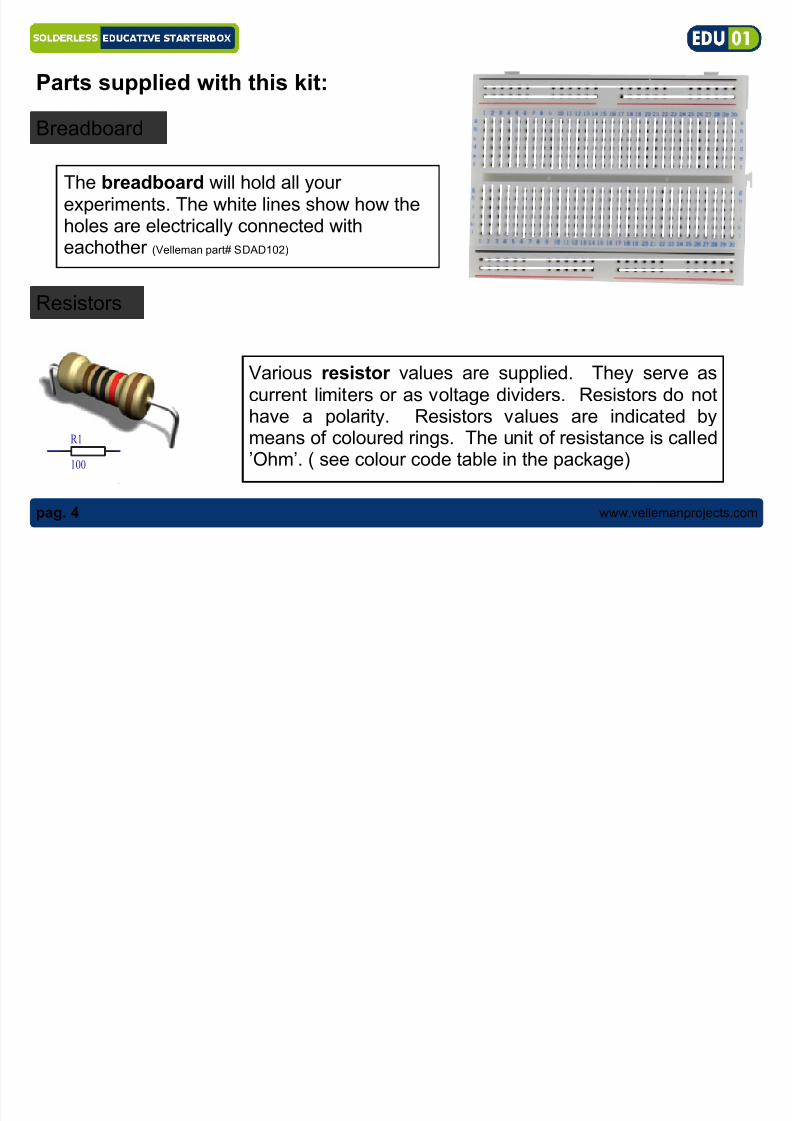
Resistors
Various resistor values are supplied. They serve ascurrent limiters or as voltage dividers. Resistors do nothave a polarity. Resistors values are indicated bymeans of coloured rings. The unit of resistance is called’Ohm’. ( see colour code table in the package)
Parts supplied with this kit:
The breadboard will hold all yourexperiments. The white lines show how theholes are electrically connected witheachother (Velleman part# SDAD102)
R1
100
Breadboard

8/13/2019 Velleman Projects Manual
http://slidepdf.com/reader/full/velleman-projects-manual 5/32
www.vellemanprojects.com Pag. 5
Capacitors
A capacitor is almost like a small battery, it can be chargedusing a power supply. Mostly used to stabilise or to filter outunwanted voltages. The unit is Farad: practical values arein µF, nF or pF. The supplied capacitor is an Electrolytic
capacitor of 10µF and has a polarity, the long lead = +(Velleman part# 10J0E)
C...
C...
Green & red LED
A LED is a Light Emitting Diode, itcan emit light using a small current(max 20mA with a 1.8V drop).
Watch the polarity, long lead = + !(Velleman part# L-7104LGD & L-7104LID)
Flat side, shortest lead = (-)
NG OK
How to bend the leads:

8/13/2019 Velleman Projects Manual
http://slidepdf.com/reader/full/velleman-projects-manual 6/32
www.vellemanprojects.compag. 6
Buzzer
A buzzer produce a signalling sound to alert
for a dangerous situation, timer confirmation,a button is pressed, ... The pitch of the buzzercan't be changed because the frequency ofthe oscillator is fixed. (Velleman part# SV3)
Push button
A push button will conduct currentwhen pushed and interrupt thecurrent when released.
(Velleman part# D6)
Inside connection
The supplied buttonhas 4 connections, butonly 2 are used.2 are interconnected.

8/13/2019 Velleman Projects Manual
http://slidepdf.com/reader/full/velleman-projects-manual 7/32
www.vellemanprojects.com Pag. 7
Transistors A transistor is an amplification device. By means of a smallcurrent, a much larger current is controlled. Transistors come intwo flavours, NPN and PNP-types, depending on the polarity.With this kit, you receive a BC557 (PNP) and a BC547 (NPN)
transistor. A transistor has 3 pins: Base, Emitter and Collector.(Velleman part# BC557B, BC547B)
LDR (Light Dependent Resistor)
E B C
C
B
EPNP
C B E
C
B
ENPN
BC547
BC557
A Light Dependent Resistor behaves
like a resistor. The resistance variouson the amount of light falling on thedevice, it decreases with increasinglight intensity. Velleman part# LDR04)

8/13/2019 Velleman Projects Manual
http://slidepdf.com/reader/full/velleman-projects-manual 8/32
www.vellemanprojects.compag. 8
Flatcable
Including in this box you can find a multi-core cable. The
wires must be separated from each other before use.This can be done using a wire-cutter or pair of scissors.Use the separate wires to connect components (indicatedin the drawing by a thick black line) Velleman part# FC8)
8x

8/13/2019 Velleman Projects Manual
http://slidepdf.com/reader/full/velleman-projects-manual 9/32
www.vellemanprojects.com Pag. 9
PROJECTSPROJECTSPROJECTS

8/13/2019 Velleman Projects Manual
http://slidepdf.com/reader/full/velleman-projects-manual 10/32
www.vellemanprojects.compag. 10
Project 1: LED with push buttonProject 1: LED with push button
As long as the push button is pressed the led will light
9 V
1K
*Not included
Flat side, shortest leg = (-)
*
RED

8/13/2019 Velleman Projects Manual
http://slidepdf.com/reader/full/velleman-projects-manual 11/32
www.vellemanprojects.com Pag. 11
Required parts: 9V battery*, 1000 ohm resistor (brown black red ), red LED,
push-button
How it works: As long as the push button ispressed, a closed circuit is formed that makes the
current flow and the LED lights up.Current flows from the (+) of the battery to thepush-button, resistor, (+) of the LED and via the (-)of the LED back to the battery.
Using a 1000ohm resistor the current will be about0.007A (7mA).
Time to experiment: What happens when you swap (+) and (-) of the led?What happens when you replace the 1000 ohm resistorwith a 100K ohm resistor (brown black yellow gold) ?
Calculation of the resistor:
resistor = battery voltage – LED voltageLED current
resistor = 9V - 1,8V = 1000ohm0,007

8/13/2019 Velleman Projects Manual
http://slidepdf.com/reader/full/velleman-projects-manual 12/32
www.vellemanprojects.compag. 12
Project 2:Project 2: Transistor acting as current amplifier Transistor acting as current amplifier
1K
4 7 K
*Not included
*
9 V
1K
B
E
C
Light up a LED using a transistor, use your finger as a switch
Jumper wire

8/13/2019 Velleman Projects Manual
http://slidepdf.com/reader/full/velleman-projects-manual 13/32
www.vellemanprojects.com Pag. 13
Required parts: 9V battery*, 1K resistor (brown black red gold), 470K resistor (yellow
purple yellow gold), red LED, BC547 transistor, wire jumper.
How it works: In this circuit, the smallcurrent flowing through your finger will beamplified by the transistor.The base current that runs via your fingerand resistor R1, is amplified by transistor T1.The amplified current flows through the LED
and R2 making the LED lit.R3 will prevent the transistor for unwantedfunctioning.
HINT: wet you finger to make the LEDlight up stronger.

8/13/2019 Velleman Projects Manual
http://slidepdf.com/reader/full/velleman-projects-manual 14/32
www.vellemanprojects.compag. 14
9 V
1K
1K C1
100K
C2
Project 3:Project 3: Astable multivibrator (flashing LEDs)Astable multivibrator (flashing LEDs) Let LEDs flash alternately
*Not included
100K
**
B B
EE
C C
WATCH THECAPACITORPOLARITY

8/13/2019 Velleman Projects Manual
http://slidepdf.com/reader/full/velleman-projects-manual 15/32

8/13/2019 Velleman Projects Manual
http://slidepdf.com/reader/full/velleman-projects-manual 16/32
www.vellemanprojects.compag. 16
9 V 1K
100K
0,5m supplied wire
*Not included
Project 4:Project 4: Simple burglar alarm with LED indication and soundSimple burglar alarm with LED indication and sound..
Make an alarm signal sound when the circuit is interrupted... **
E
BC

8/13/2019 Velleman Projects Manual
http://slidepdf.com/reader/full/velleman-projects-manual 17/32
www.vellemanprojects.com Pag. 17
Required parts: 9V battery*, 1K resistor (brown black red gold), 100K resistor (brown
black yellow gold), red LED, BC547 transistor, buzzer, 0,5m supplied wire.
How it works: An alarm sounds when thenormally closed security circuit (here
indicated as ‘WIRE’) is interrupted.Replace this normally closed circuit(WIRE) by a normally closed window ordoor switch; when e.g. the window isopened the contact within the windowswitch is interrupted, the security circuit isopened and the buzzer sounds.The alarm signal ends as soon as thesecurity circuit is closed again.

8/13/2019 Velleman Projects Manual
http://slidepdf.com/reader/full/velleman-projects-manual 18/32
www.vellemanprojects.compag. 18
9 V 1K10K
*Not included
10K
Project 5:Project 5: Light detector Light detector
Switch on a LED when there is sufficient light **
B
C
E

8/13/2019 Velleman Projects Manual
http://slidepdf.com/reader/full/velleman-projects-manual 19/32
www.vellemanprojects.com Pag. 19
Required parts: 9V battery*, 1K resistor (brown black red gold), 2x 10K resistor
(brown black orange gold), red LED, BC547 transistor, LDR.
How it works: A LED lights up when enough
light hits the LDR. The LDR is a light sensitiveresistor (Light Dependent Resistor), in darkconditions it has a high resistance, and in lightconditions its resistance becomes low.
Across the LDR is a positive potential which isfed to the base of the transistor enabling it toswitch. Resistor R2 creates a switching pointwhich determines when the transistor starts toconduct. Resistor R1 limits the current that
flows through the LDR.

8/13/2019 Velleman Projects Manual
http://slidepdf.com/reader/full/velleman-projects-manual 20/32
www.vellemanprojects.compag. 20
Jumper wire
1K 9 V
*Not included
Project 6:Project 6: polarity tester.polarity tester.
Check the polarity of a battery*
GREEN RED

8/13/2019 Velleman Projects Manual
http://slidepdf.com/reader/full/velleman-projects-manual 21/32
www.vellemanprojects.com Pag. 21
Required parts: 9V battery*, 1K resistor (brown black red gold), red LED, green LED,
wire jumper
How it works: When the 9V battery isconnected to the circuit with the right
polarity the green LED (good) will lightup. Current can flow from the "+" of thebattery through the green LED and viathe resistor back to the "–" of the battery.
The red LED (wrong) will not light up as itis polarised in the opposite direction.When swapping the connection of thebattery (switch the red and the blackwires) the red LED will light up. This way
we can determine whether a battery isconnected the right way or not.
GREEN RED

8/13/2019 Velleman Projects Manual
http://slidepdf.com/reader/full/velleman-projects-manual 22/32
www.vellemanprojects.compag. 22
T2
*Not included
10K 1K
1K1K
T1
SW2 SW1
9 V
Jumper wire
Jumper wire
Jumper wire
Project 7: StartProject 7: Start--stop circuit.stop circuit.
Control a LED using 2 pushbuttons ***
B
C
B
E
C
E

8/13/2019 Velleman Projects Manual
http://slidepdf.com/reader/full/velleman-projects-manual 23/32
www.vellemanprojects.com Pag. 23
Required parts: 9V battery*, 3 x1K resistor (brown black red gold), 10K resistor
(brown black orange gold), red LED, 2 x push-button, 1x BC547 transistor, 1x BC557transistor, 5 x wire jumper
How it works: The “START” button willlight up the LED; it will remain on when
the pushbutton is released. To switch offthe LED, press the “STOP” button.T1 and T2 are in state of rest (OFF, nocurrent). By pressing the “START” but-ton a current flows via R4 through the
LED. At the same time the base of T2 ispulled low (was high via R1). Since thevalue of R3 is much lower than R1 thevoltage on the base of T2 drops makingit conduct and via the collector of T2 and
R2. T1 also starts to conduct. From this point on, both transistors keep each other in con-ducting state, even when the “START” button is released. Pressing the “STOP” button willend the current flow towards the base of T1 and it will stop conducting. The circuit is inter-rupted and T2 will also stop conducting. The LED will turn off.

8/13/2019 Velleman Projects Manual
http://slidepdf.com/reader/full/velleman-projects-manual 24/32
www.vellemanprojects.compag. 24
1K
Jumper wire
100K
*Not included
Jumper wire
10M
10µF 9 V
Jumper wire
Project 8: Timer circuit.Project 8: Timer circuit.
Make a LED switch off after a certain time ***
E
C
B
E
C
B

8/13/2019 Velleman Projects Manual
http://slidepdf.com/reader/full/velleman-projects-manual 25/32
www.vellemanprojects.com Pag. 25
Required parts: 9V battery*, 1K resistor (brown black red gold), 100K resistor (brown
black orange gold), 1M resistor (brown black green gold), Red LED, push-button, 2xBC547 transistor, 10µF electrolytic capacitor, 3 x wire jumper
How it works: When pushing the pushbutton shortly, the LED will turn on and aftera while it will go out. By pushing the pushbutton the capacitor will quickly charge; whenreleasing the button the capacitor will releaseits stored energy via both transistors – bothwill start to conduct and the LED will light up.The current needed to make T2 conduct islimited as T1 and T2 form a Darlington tran-sistor circuit. The time needed to dischargethe capacitor is also determined by resistor
R1. The smaller R1 the faster the capacitor isdischarged and the LED switches off. WhenR1 is removed, the capacitor dischargessolely via the base current of T1. Switchingoff is a lot slower now and takes ± 1 minute. The total gain of both transistors can be calculated: ß = ß(T1) x ß(T2)
In electronics, the Darlington circuit is astructure consisting of two bipolar
transistors connected in such a waythat the current amplified by the firsttransistor is amplified further by the
second one. This configuration gives amuch higher current gain than each
transistor taken separately.
R110M

8/13/2019 Velleman Projects Manual
http://slidepdf.com/reader/full/velleman-projects-manual 26/32
www.vellemanprojects.compag. 26
9 V 10K
*Not included
10µF
10K
1k
1k
100K100
Jumper wire
Project 9: Light switchProject 9: Light switch
Make a LED switch on when it becomes dark ***
EC
B
EC
B

8/13/2019 Velleman Projects Manual
http://slidepdf.com/reader/full/velleman-projects-manual 27/32

8/13/2019 Velleman Projects Manual
http://slidepdf.com/reader/full/velleman-projects-manual 28/32
www.vellemanprojects.compag. 28
wire
*Not included
9 V
10K
MAX
Do not use aflammablesubstance
470K
Project 10: Water alarmProject 10: Water alarm
Make a liquid level trigger an alarm **
EC
B
E
C
B

8/13/2019 Velleman Projects Manual
http://slidepdf.com/reader/full/velleman-projects-manual 29/32
www.vellemanprojects.com Pag. 29
Required parts: 9V battery, 10K resistor (brown black orange gold), 470K resistor
(yellow purple yellow gold), buzzer, 2x BC547 transistor, 2 wires
How it works: The 2 sensor wires
must be placed in a tank at a certaindistance (e.g. use a drinking cup). Fillup the tank with a conducting liquid(e.g. water) until the level reachesboth sensor wires. A small current
will flow via R2 towards the base ofT2. The base is protected againstinterference with a resistor R1.
T1 & T2 are configured as a Darlington switch hence only a very small current is neededto make T1 conduct and activate the alarm sound.

8/13/2019 Velleman Projects Manual
http://slidepdf.com/reader/full/velleman-projects-manual 30/32
www.vellemanprojects.compag. 30
Jumper wire
*Not included
1 K
1 0 0 K
1 K
1 0 0 K
1 K
1 0 0 K
9 V J u m p e r w i r e
Project 11:Project 11: Running light with 3 LEDsRunning light with 3 LEDs
Make 3 LEDs without control light up successively
***
BB
E
B
E E
C C C

8/13/2019 Velleman Projects Manual
http://slidepdf.com/reader/full/velleman-projects-manual 31/32
www.vellemanprojects.com Pag. 31
Required parts: 9V battery*, 3x1K resistor (brown black red gold), 3x100K resistor
(brown black yellow gold), 3 x red LED, 3x BC547 transistor, 3x10µF electrolytic capaci-tor, 2x wire jumper
This circuit makes each LED light up shortly in succession. The circuit consists of 3 identicalchannels. It is theoretically possible to expand; per LED a similar circuit is needed in serieswith the previous. The capacitor of the next channel is charged when the transistor of the
previous channel is not conducting. As long as a certain transistor is not conducting, the rele-vant LED will light up. Capacitor C4 is added to the circuit to create a certain starting condi-tion when connecting power and to ensure a good operation.
Time to experiment: What happens when you change the value of R1, R2 and R3 to 10K?

8/13/2019 Velleman Projects Manual
http://slidepdf.com/reader/full/velleman-projects-manual 32/32
Learn how to connect your computerwith the outside world, master theUSB communication with tutorial examples.
Play with LED indicators and learn how to driveLCDisplays.
Enter the world of microcontrollerprogramming, easy step by step instructions.Includes programmer and test board.
Modifications and typographical errors reserved. © Velleman nv, Legen Heirweg 33 - 9890 Gavere (België)HEDU01 - 2011- ED1 5 4 1 0 3 2 9 4 3 8 1 1 1
Fun solar powered projects. Learn all about solarenergy.
Learn how to solder, build different exciting projects.Includes spare components anddemo boards.
This board with different signals willteach you how to use an oscilloscope.Optimized instructions for use of our HPS140oscilloscope. YouTube demo movies.
STARTER BOX SOLDER EDUCATIVE
TUTOR KIT PICTM
EXPERIMENT KIT SOLAR ENERGY02
04
06 EDUKIT SCOPE
03
05 TUTOR BOARD USB
The Microchi p name and logo, PIC, and PICmicro are registered trademarks of Microch ip Technology Inc. in
the USA and oth er countr ies.