venue personal q guide -...
TRANSCRIPT
VENUE Personal QGuide
Digidesign2001 Junipero Serra BoulevardDaly City, CA 94014-3886 USA
Technical Support (USA)
Visit the Digidesign Online Support Center atwww.digidesign.com/support
Product Information
For company and product information,visit us on the web at www.digidesign.com
PN 9321-61362-00 REV A 04/09
Copyright
© 2009 Avid Technology, Inc. All rights reserved. This guide may not be duplicated in part or in whole without the prior written consent of Avid Technology, Inc.
Avid, Digidesign, D-Show,Profile and Pro Tools are trademarks or registered trademarks of Avid Technology, Inc. in the U.S. and/or other countries. All other trademarks contained herein are the property of their respective owners.
Product features, specifications, system requirements, and availability are subject to change without notice.
Part Number 9321-61362-00 REV A 04/09
Documentation Feedback
At Digidesign, we are always looking for ways to improve our documentation. If you have comments, corrections, or suggestions regarding our documentation, email us at [email protected].
Communications & Safety Regulation Information
Compliance StatementThe models PQ Rack and PQ Controller comply with the following standards regulating emissions and immunity:• FCC Part 15 Class B• EN55103 – 1, environment E3• EN55103 – 2, environment E3• AS/NZS 3548 Class B• CISPR 22 Class B• ICES-003 Class B
Radio and Television Interference
This equipment has been tested and found to comply with the limits for a Class B digital device, pursuant to Part 15 of the FCC Rules.
DECLARATION OF CONFORMITY
We, Digidesign,
2001 Junipero Serra Blvd.
Daly City, California 94014-3886, USA
650-731-6100
declare under our sole responsibility that the products
PQ Rack and PQ Controller
complies with Part 15 of FCC Rules.
Operation is subject to the following two conditions: (1) this device may not cause harmful interference, and (2) this device must accept any interference reeived, including interference that may cause undesired operation.
Communications Statement
NOTE: This equipment has been tested and found to comply with the limits for a Class B digital device, pursuant to Part 15 of the FCC Rules. These limits are designed to provide reasonable protection against harmful interference in a residential installation. This equipment generates, uses, and can radiate radio frequency energy and, if not installed and used in accordance with the instructions, may cause harmful interference to radio communications. However, there is no guarantee that interference will not occur in a particular installation. If this equipment does cause harmful interference to radio or television reception, which can be determined by turning the equipment off and on, the user is encouraged to try and correct the interference by one or more of the following measures:• Reorient or locate the receiving antenna.• Increase the separation between the equipment and receiver.• Connect the equipment into an outlet on a circuit different from that to which
the receiver is connected.• Consult the dealer or an experienced radio/TV technician for help.
Any modifications to the unit, unless expressly approved by Digidesign, could void the user's authority to operate the equipment.
Canadian Compliance Statement:This Class B digital apparatus complies with Canadian ICES-003Cet appareil numérique de la classe B est conforme à la norme NMB-003 du Canada.
CE Compliance Statement:
Digidesign is authorized to apply the CE (Conformité Europénne) mark on this compliant equipment thereby declaring conformity to EMC Directive 89/336/EEC and Low Voltage Directive 73/23/EEC.
Australian Compliance:
Radio and Television InterferenceThis equipment has been tested and found to comply with the limits for a Class B digital device, pursuant to Part 15 of the FCC Rules.
Safety StatementThis equipment has been tested to comply with USA and Canadian safety certification in accordance with the specifications of UL Standards: UL60065 7th /IEC 60065 7th and Canadian CAN/CSA C22.2 60065:03. Digidesign Inc., has been authorized to apply the appropriate UL & CUL mark on its compliant equipment.
Warning
Important Safety Instructions1) Read these instructions.2) Keep these instructions.3) Heed all warnings.4) Follow all instructions.5) Do not use this apparatus near water.6) Clean only with dry cloth.7) Do not block any ventilation openings. Install in accordance with the manufacturer’s instructions.8) Do not install near any heat sources such as radiators, heat registers, stoves, or other apparatus (including amplifiers) that produce heat.9) Do not defeat the safety purpose of the polarized or grounding-type plug. A polarized plug has two blades with one wider than the other. A grounding-type plug has two blades and a third grounding prong. The wide blade or the third prong are provided for your safety. If the provided plug does not fit into your outlet, consult an electrician for replacement of the obsolete outlet.10) Protect the power cord from being walked on or pinched particularly at plugs, convenience receptacles, and the point where they exit from the apparatus.11) Only use attachments/accessories specified by the manufacturer.12) CAUTION – Refer all servicing to qualified service personnel only. To reduce the risk of electric shock, do not perform any servicing other than that contained in the operating instructions unless you are qualified to do so.13) WARNING – To reduce the risk of fire or electric shock, do not expose this apparatus to rain or moisture.14) To reduce the risk of electric shock, grounding of the center of the plug must be maintained, if applicable.15) The AC mains plug or appliance coupler shall be readily available to the operator as a means of power disconnectioin.
Contents
Chapter 1. Introduction . . . . . . . . . . . . . . . . . . . . . . . . . . . . . . . . . . . . . . . . . . . . . . . . . . . . . . . . . . . . . . . . . . . . . . . . . . . 1
Personal Q System Features. . . . . . . . . . . . . . . . . . . . . . . . . . . . . . . . . . . . . . . . . . . . . . . . . . . . . . . . . . . . . . . . . . . . . . 1
Personal Q System Components . . . . . . . . . . . . . . . . . . . . . . . . . . . . . . . . . . . . . . . . . . . . . . . . . . . . . . . . . . . . . . . . . . . 1
System Expansion Options . . . . . . . . . . . . . . . . . . . . . . . . . . . . . . . . . . . . . . . . . . . . . . . . . . . . . . . . . . . . . . . . . . . . . . . 1
Operational Requirements . . . . . . . . . . . . . . . . . . . . . . . . . . . . . . . . . . . . . . . . . . . . . . . . . . . . . . . . . . . . . . . . . . . . . . . 2
Connection Requirements . . . . . . . . . . . . . . . . . . . . . . . . . . . . . . . . . . . . . . . . . . . . . . . . . . . . . . . . . . . . . . . . . . . . . . . 2
PQ Rack Overview . . . . . . . . . . . . . . . . . . . . . . . . . . . . . . . . . . . . . . . . . . . . . . . . . . . . . . . . . . . . . . . . . . . . . . . . . . . . . 3
PQ Controller Overview . . . . . . . . . . . . . . . . . . . . . . . . . . . . . . . . . . . . . . . . . . . . . . . . . . . . . . . . . . . . . . . . . . . . . . . . . 4
Chapter 2. Connecting the Personal Q System . . . . . . . . . . . . . . . . . . . . . . . . . . . . . . . . . . . . . . . . . . . . . . . . . . . . . . 7
Connecting Personal Q System Components . . . . . . . . . . . . . . . . . . . . . . . . . . . . . . . . . . . . . . . . . . . . . . . . . . . . . . . . . . 7
Power Connections . . . . . . . . . . . . . . . . . . . . . . . . . . . . . . . . . . . . . . . . . . . . . . . . . . . . . . . . . . . . . . . . . . . . . . . . . . . . 9
Applying Power to the Personal Q System . . . . . . . . . . . . . . . . . . . . . . . . . . . . . . . . . . . . . . . . . . . . . . . . . . . . . . . . . . . . 9
Updating PQ System Firmware . . . . . . . . . . . . . . . . . . . . . . . . . . . . . . . . . . . . . . . . . . . . . . . . . . . . . . . . . . . . . . . . . . . . 9
Mounting a PQ Controller to a Microphone Stand . . . . . . . . . . . . . . . . . . . . . . . . . . . . . . . . . . . . . . . . . . . . . . . . . . . . . . . 9
Using Two Personal Q Systems . . . . . . . . . . . . . . . . . . . . . . . . . . . . . . . . . . . . . . . . . . . . . . . . . . . . . . . . . . . . . . . . . . . 11
Chapter 3. Using the Personal Q System . . . . . . . . . . . . . . . . . . . . . . . . . . . . . . . . . . . . . . . . . . . . . . . . . . . . . . . . . . . 13
Configuring the Personal Q System . . . . . . . . . . . . . . . . . . . . . . . . . . . . . . . . . . . . . . . . . . . . . . . . . . . . . . . . . . . . . . . . 13
Setting Up PQ Controllers . . . . . . . . . . . . . . . . . . . . . . . . . . . . . . . . . . . . . . . . . . . . . . . . . . . . . . . . . . . . . . . . . . . . . . . 15
Configuring Personal Q Mixers . . . . . . . . . . . . . . . . . . . . . . . . . . . . . . . . . . . . . . . . . . . . . . . . . . . . . . . . . . . . . . . . . . . 16
Controlling a Personal Q Mixer from a PQ Controller . . . . . . . . . . . . . . . . . . . . . . . . . . . . . . . . . . . . . . . . . . . . . . . . . . . . 17
Calling the Console from the PQ Controller . . . . . . . . . . . . . . . . . . . . . . . . . . . . . . . . . . . . . . . . . . . . . . . . . . . . . . . . . . 18
Locking Out PQ Controllers. . . . . . . . . . . . . . . . . . . . . . . . . . . . . . . . . . . . . . . . . . . . . . . . . . . . . . . . . . . . . . . . . . . . . . 19
Troubleshooting . . . . . . . . . . . . . . . . . . . . . . . . . . . . . . . . . . . . . . . . . . . . . . . . . . . . . . . . . . . . . . . . . . . . . . . . . . . . . 19
Contents iii

VENUE Personal Q Guideiv
Chapter 1: Introduction
The VENUE Personal Q (PQ) system lets performers remotely control their own monitor mixes on a VENUE system using ei-ther a VENUE D-Show® Main or VENUE Profile™ console, paired with a VENUE Stage Rack and a VENUE FOH Rack.
D-Show Main and Profile consoles provide eight built-in, 12 x 2 PQ mixers that can be used to create up to eight indepen-dent stereo monitor mixes. After a PQ mixer is set up at the mix position, it can be controlled by the mix engineer from the Output section of the console, or by an onstage performer using a PQ Controller.
The PQ system carries control data to and from the console, al-lowing you to adjust PQ mixer input level, input pan/balance, and output level. The PQ system does not carry audio signals; audio signals for monitor mixes are output from any physical outputs on the Stage Rack or FOH Rack.
Personal Q System FeaturesThe Personal Q system provides remote operation of controls on the console, and mirrors any changes made to the corre-sponding controls on the console.
The Personal Q system consists of at least one PQ Rack and one PQ Controller.
PQ Rack Features• Provides connections for up to eight PQ Controllers
PQ Controller Features• Four rotary encoder controls with LED rings for level,
pan/balance, solo, and metering of PQ mixer inputs(1–8, L, R, and User Inputs)
• Four on/off switches for control of PQ mixer input on/off status
• Rotary encoder control with LED ring for master volume of PQ mixer output
• Four 6-character displays for input and control names
• Console call feature allows performer to activate call mes-sage on console display
• Lockout feature allows performer or console operator to temporarily lock out PQ Controller from control changes
Personal Q System ComponentsThe following components are included in a Personal Q system:
PQ Rack• PQ Rack unit
• AC power cord
• PQ Link Cable (10 ft/3 m)
PQ Controller(Up to 8 PQ Controllers can be connected to each PQ Rack)
• PQ Controller unit
• PQ Controller cable (50 ft/15 m)
System Expansion OptionsThe Personal Q system allows independent control of up to eight individual PQ mixes.
PQ Racks In VENUE systems with two Stage Racks, one PQ Rack can be connected to each Stage Rack, for a total of two PQ Rack units. When two PQ Racks are used, dual control of each PQ mix (up to a maximum of 8 available PQ mixers) is possible. (This is useful when a single performer has two posi-tions onstage.)
PQ Controllers Each PQ Rack can accommodate 8 PQ Control-lers, for a maximum of 16 PQ Controllers (2 controllers for each of the 8 available PQ mixers) on a VENUE system.
For more information on expansion options for VENUE sys-tems, visit the Digidesign Web site (www.digidesign.com).
Chapter 1: Introduction 1
Operational Requirements
Temperature and Ventilation
VENUE system components should be operated away from heat sources and with adequate ventilation.
Storage
VENUE system components should be stored and transported at temperatures not lower than 0 degrees F (–18 degrees C) and not exceeding 140 degrees F (60 degrees C).
Operation
VENUE system components should be operated at tempera-tures not lower than 40 degrees F (4 degrees C) and not ex-ceeding 115 degrees F (46 degrees C).
Water and Moisture
VENUE system components should be operated away from sources of direct moisture and should be kept clear of liquids that might spill into the units.
If condensation is present on a VENUE system component, leave the unit to dry in ambient air for at least one hour before powering the unit on.
Cleaning and Maintenance
If you need to clean the surface of a VENUE system compo-nent, use a dry cloth. Do not apply any cleaning solutions, spray cleaners, or abrasives to the surface.
VENUE Personal Q Guide2
Connection Requirements
Power Connections
PQ Rack Each PQ Rack requires its own power connection. Make sure your power source is correctly rated for the number of units you are connecting. A surge protected power source (not included) is highly recommended.
PQ Controllers Each PQ Controller is powered by the PQ Rack through its PQ Controller cable connection.
PQ Rack Overview
PQ Rack Front Panel
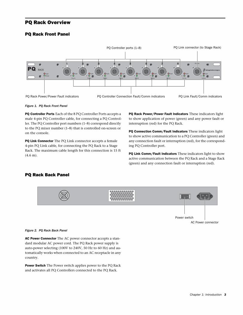
Figure 1. PQ Rack Front Panel
PQ Controller ports (1–8) PQ Link connector (to Stage Rack)
PQ Controller Connection Fault/Comm indicators PQ Link Fault/Comm indicatorsPQ Rack Power/Power Fault indicators
PQ Controller Ports Each of the 8 PQ Controller Ports accepts a male 4-pin PQ Controller cable, for connecting a PQ Control-ler. The PQ Controller port numbers (1–8) correspond directly to the PQ mixer number (1–8) that is controlled on-screen or on the console.
PQ Link Connector The PQ Link connector accepts a female 4-pin PQ Link cable, for connecting the PQ Rack to a Stage Rack. The maximum cable length for this connection is 15 ft (4.6 m).
PQ Rack Power/Power Fault Indicators These indicators light to show application of power (green) and any power fault or interruption (red) for the PQ Rack.
PQ Connection Comm/Fault Indicators These indicators light to show active communication to a PQ Controller (green) and any connection fault or interruption (red), for the correspond-ing PQ Controller port.
PQ Link Comm/Fault Indicators These indicators light to show active communication between the PQ Rack and a Stage Rack (green) and any connection fault or interruption (red).
PQ Rack Back Panel
Figure 2. PQ Rack Back Panel
Power switch
AC Power connector
AC Power Connector The AC power connector accepts a stan-dard modular AC power cord. The PQ Rack power supply is auto-power selecting (100V to 240V, 50 Hz to 60 Hz) and au-tomatically works when connected to an AC receptacle in any country.
Power Switch The Power switch applies power to the PQ Rack and activates all PQ Controllers connected to the PQ Rack.
Chapter 1: Introduction 3
PQ Controller Overview
PQ Controller Top Panel
VENUE Personal Q Guide4
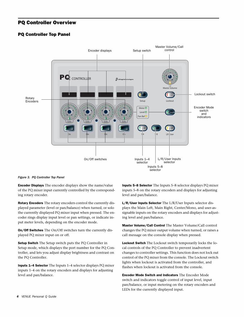
Figure 3. PQ Controller Top Panel
Encoder displays
RotaryEncoders
On/Off switches Inputs 1–4selector
Inputs 5–8selector
L/R/User Inputsselector
Setup switchMaster Volume/Call
control
Lockout switch
Encoder Modeswitchand
indicators
Encoder Displays The encoder displays show the name/value of the PQ mixer input currently controlled by the correspond-ing rotary encoder.
Rotary Encoders The rotary encoders control the currently dis-played parameter (level or pan/balance) when turned, or solo the currently displayed PQ mixer input when pressed. The en-coder rings display input level or pan settings, or indicate in-put meter levels, depending on the encoder mode.
On/Off Switches The On/Off switches turn the currently dis-played PQ mixer input on or off.
Setup Switch The Setup switch puts the PQ Controller in Setup mode, which displays the port number for the PQ Con-troller, and lets you adjust display brightness and contrast on the PQ Controller.
Inputs 1–4 Selector The Inputs 1–4 selector displays PQ mixer inputs 1–4 on the rotary encoders and displays for adjusting level and pan/balance.
Inputs 5–8 Selector The Inputs 5–8 selector displays PQ mixer inputs 5–8 on the rotary encoders and displays for adjusting level and pan/balance.
L/R/User Inputs Selector The L/R/User Inputs selector dis-plays the Main Left, Main Right, Center/Mono, and user-as-signable inputs on the rotary encoders and displays for adjust-ing level and pan/balance.
Master Volume/Call Control The Master Volume/Call control changes the PQ mixer output volume when turned, or raises a call message on the console display when pressed.
Lockout Switch The Lockout switch temporarily locks the lo-cal controls of the PQ Controller to prevent inadvertent changes to controller settings. This function does not lock out control of the PQ mixer from the console. The Lockout switch lights when lockout is activated from the controller, and flashes when lockout is activated from the console.
Encoder Mode Switch and Indicators The Encoder Mode switch and indicators toggle control of input level, input pan/balance, or input metering on the rotary encoders and LEDs for the currently displayed input.
PQ Controller Back Panel
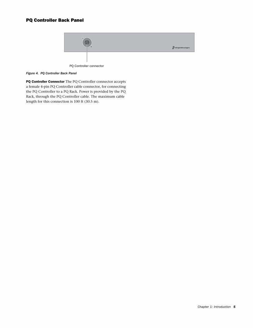
Figure 4. PQ Controller Back Panel
PQ Controller connector
PQ Controller Connector The PQ Controller connector accepts a female 4-pin PQ Controller cable connector, for connecting the PQ Controller to a PQ Rack. Power is provided by the PQ Rack, through the PQ Controller cable. The maximum cable length for this connection is 100 ft (30.5 m).
Chapter 1: Introduction 5

VENUE Personal Q Guide6
Chapter 2: Connecting the Personal Q System
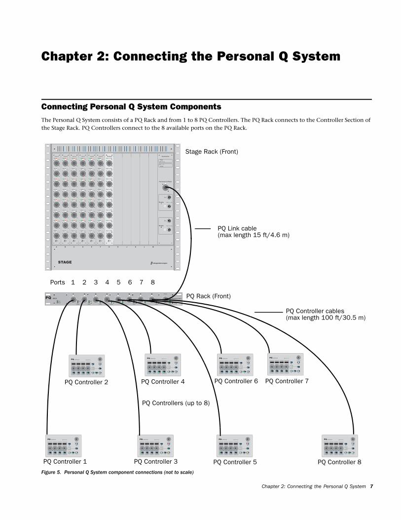
Connecting Personal Q System ComponentsThe Personal Q System consists of a PQ Rack and from 1 to 8 PQ Controllers. The PQ Rack connects to the Controller Section of the Stage Rack. PQ Controllers connect to the 8 available ports on the PQ Rack.
Figure 5. Personal Q System component connections (not to scale)
Stage Rack (Front)
PQ Controllers (up to 8)
PQ Rack (Front)
PQ Link cable
PQ Controller cables
(max length 15 ft/4.6 m)
(max length 100 ft/30.5 m)
PQ Controller 1
PQ Controller 2
PQ Controller 3
PQ Controller 4
PQ Controller 5
PQ Controller 6 PQ Controller 7
PQ Controller 8
1 2 3 4 5 6 7 8Ports
Chapter 2: Connecting the Personal Q System 7
Connecting the PQ Rack to the Stage Rack
VENUE Personal Q Guide8
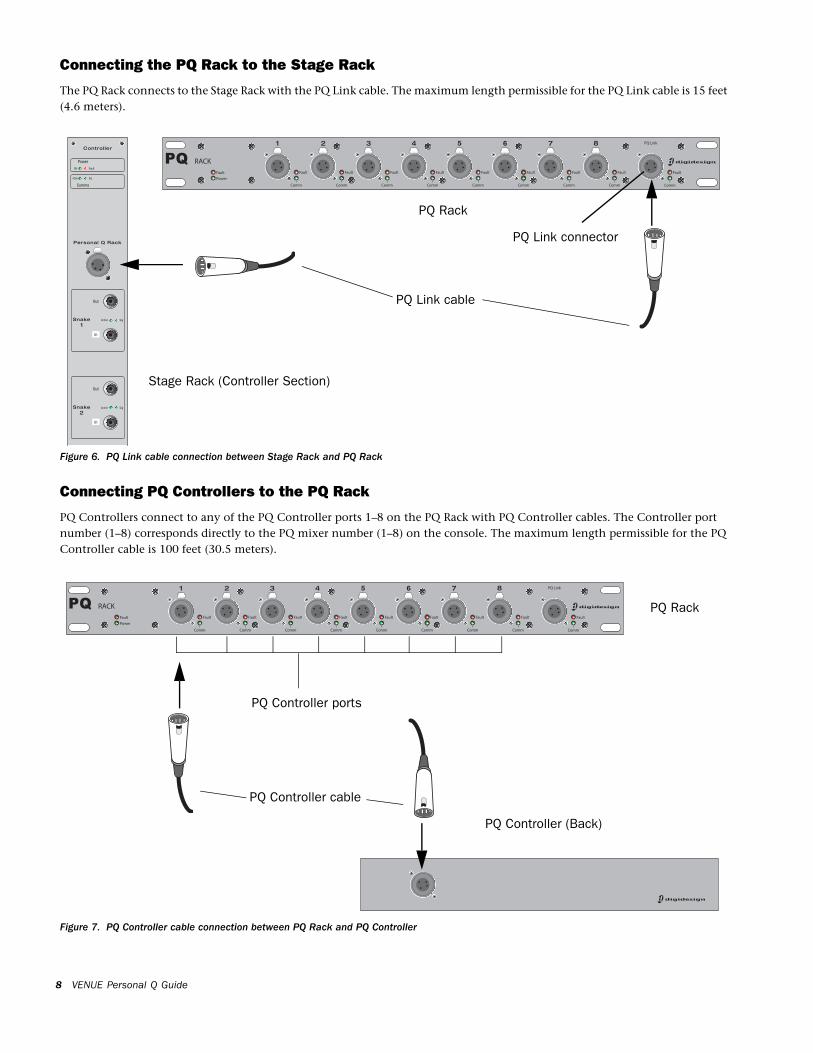
The PQ Rack connects to the Stage Rack with the PQ Link cable. The maximum length permissible for the PQ Link cable is 15 feet (4.6 meters).
Figure 6. PQ Link cable connection between Stage Rack and PQ Rack
PQ Rack
Stage Rack (Controller Section)
PQ Link connector
PQ Link cable
Connecting PQ Controllers to the PQ Rack
PQ Controllers connect to any of the PQ Controller ports 1–8 on the PQ Rack with PQ Controller cables. The Controller port number (1–8) corresponds directly to the PQ mixer number (1–8) on the console. The maximum length permissible for the PQ Controller cable is 100 feet (30.5 meters).
Figure 7. PQ Controller cable connection between PQ Rack and PQ Controller
PQ Rack
PQ Controller (Back)
PQ Controller ports
PQ Controller cable
Power Connections
PQ Rack
The power supply in the PQ Rack is auto-power selecting (100V to 240V, 50 Hz to 60 Hz). A modular IEC power cable is provided.
PQ Controllers
PQ Controllers are powered through the connection to the PQ Rack. No additional power connection is required.
Applying Power to the Personal Q System
PQ Rack
The PQ Rack can be connected to the Stage Rack and powered up or down at any time before or after power up of the VENUE system.
PQ Controllers
PQ Controllers can be connected to or disconnected from a PQ Rack at any time.
Updating PQ System FirmwareIf new firmware is available for a PQ Rack or PQ Controller unit, it is automatically downloaded to the unit when it is connected to the VENUE system. The LEDs on the Rack or Controller unit flash in sequence to indicate firmware is being updated. The unit is unavailable during the firmware update.
Firmware download status can be monitored on-screen from the Devices tab of the Options page.
Firmware updates can take several minutes to complete. Make sure to allow time for all connected units to finish the update process.
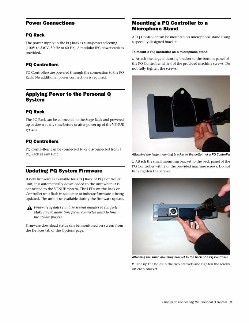
Mounting a PQ Controller to a Microphone StandA PQ Controller can be mounted on microphone stand using a specially-designed bracket.
To mount a PQ Controller on a microphone stand:
1 Attach the large mounting bracket to the bottom panel of the PQ Controller with 4 of the provided machine screws. Do not fully tighten the screws.
1 Attach the small mounting bracket to the back panel of the PQ Controller with 2 of the provided machine screws. Do not fully tighten the screws.
2 Line up the holes in the two brackets and tighten the screws on each bracket.
Attaching the large mounting bracket to the bottom of a PQ Controller
Attaching the small mounting bracket to the back of a PQ Controller
Chapter 2: Connecting the Personal Q System 9
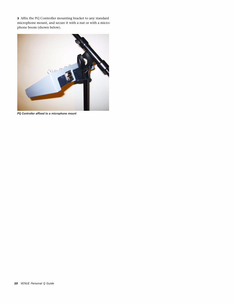
3 Affix the PQ Controller mounting bracket to any standard microphone mount, and secure it with a nut or with a micro-phone boom (shown below).
PQ Controller affixed to a microphone mount
VENUE Personal Q Guide10
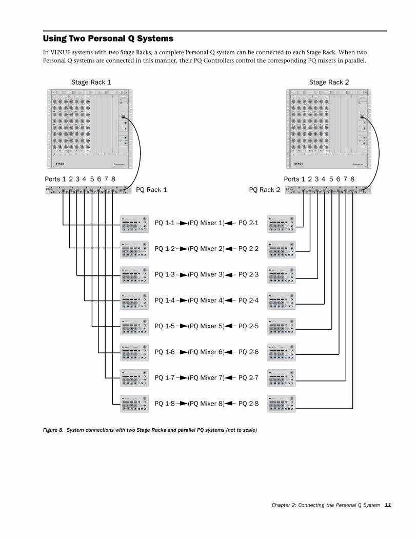
Using Two Personal Q SystemsIn VENUE systems with two Stage Racks, a complete Personal Q system can be connected to each Stage Rack. When two Personal Q systems are connected in this manner, their PQ Controllers control the corresponding PQ mixers in parallel.
Figure 8. System connections with two Stage Racks and parallel PQ systems (not to scale)
Stage Rack 1
PQ Rack 1
Stage Rack 2
PQ Rack 2
PQ 1-1
PQ 1-2
PQ 1-3
PQ 1-4
PQ 1-5
PQ 1-6
PQ 1-7
PQ 1-8
PQ 2-1
PQ 2-2
PQ 2-3
PQ 2-4
PQ 2-5
PQ 2-6
PQ 2-7
PQ 2-8
(PQ Mixer 1)
(PQ Mixer 2)
(PQ Mixer 3)
(PQ Mixer 4)
(PQ Mixer 5)
(PQ Mixer 6)
(PQ Mixer 7)
(PQ Mixer 8)
1 2 3 4 5 6 7 8Ports 1 2 3 4 5 6 7 8Ports
Chapter 2: Connecting the Personal Q System 11

VENUE Personal Q Guide12
Chapter 3: Using the Personal Q System
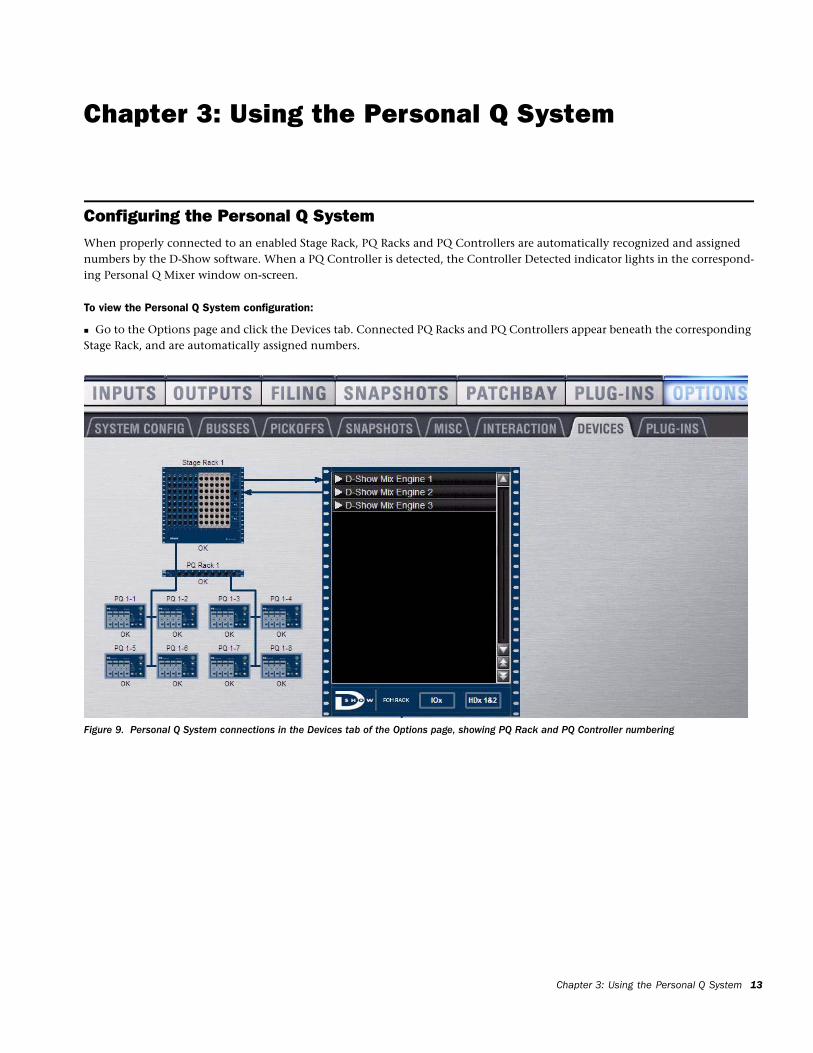
Configuring the Personal Q SystemWhen properly connected to an enabled Stage Rack, PQ Racks and PQ Controllers are automatically recognized and assigned numbers by the D-Show software. When a PQ Controller is detected, the Controller Detected indicator lights in the correspond-ing Personal Q Mixer window on-screen.
To view the Personal Q System configuration:
Go to the Options page and click the Devices tab. Connected PQ Racks and PQ Controllers appear beneath the corresponding Stage Rack, and are automatically assigned numbers.
Figure 9. Personal Q System connections in the Devices tab of the Options page, showing PQ Rack and PQ Controller numbering
Chapter 3: Using the Personal Q System 13
PQ Rack Numbering
Each PQ Rack number is automatically assigned, and corresponds to the number of the Stage Rack where it is connected.
PQ Controller Numbering
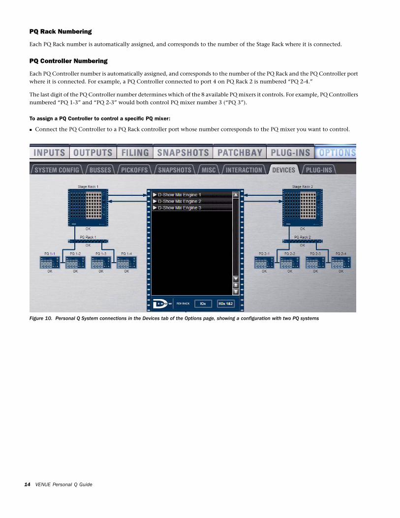
Each PQ Controller number is automatically assigned, and corresponds to the number of the PQ Rack and the PQ Controller port where it is connected. For example, a PQ Controller connected to port 4 on PQ Rack 2 is numbered “PQ 2-4.”
The last digit of the PQ Controller number determines which of the 8 available PQ mixers it controls. For example, PQ Controllers numbered “PQ 1-3” and “PQ 2-3” would both control PQ mixer number 3 (“PQ 3”).
To assign a PQ Controller to control a specific PQ mixer:
Connect the PQ Controller to a PQ Rack controller port whose number corresponds to the PQ mixer you want to control.
VENUE Personal Q Guide14
Figure 10. Personal Q System connections in the Devices tab of the Options page, showing a configuration with two PQ systems
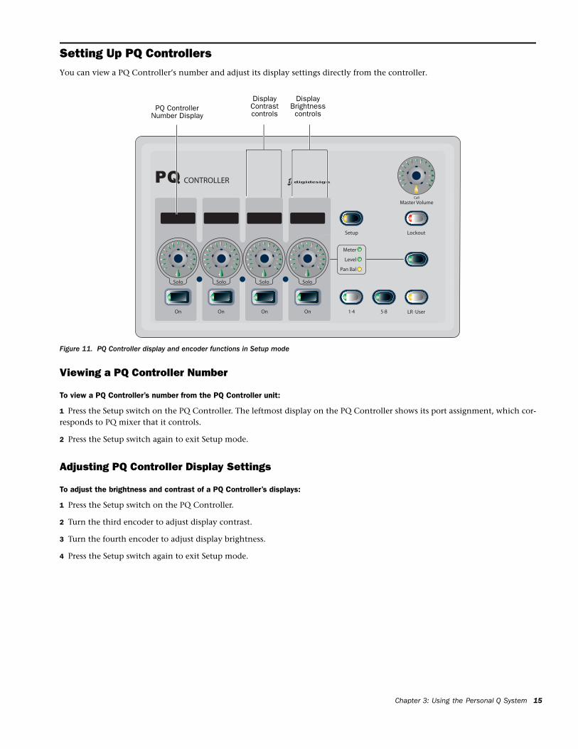
Setting Up PQ ControllersYou can view a PQ Controller’s number and adjust its display settings directly from the controller.
Viewing a PQ Controller Number
To view a PQ Controller’s number from the PQ Controller unit:
1 Press the Setup switch on the PQ Controller. The leftmost display on the PQ Controller shows its port assignment, which cor-responds to PQ mixer that it controls.
2 Press the Setup switch again to exit Setup mode.
Adjusting PQ Controller Display Settings
To adjust the brightness and contrast of a PQ Controller’s displays:
1 Press the Setup switch on the PQ Controller.
2 Turn the third encoder to adjust display contrast.
3 Turn the fourth encoder to adjust display brightness.
4 Press the Setup switch again to exit Setup mode.
Figure 11. PQ Controller display and encoder functions in Setup mode
PQ ControllerNumber Display
DisplayContrast
DisplayBrightnesscontrolscontrols
Chapter 3: Using the Personal Q System 15
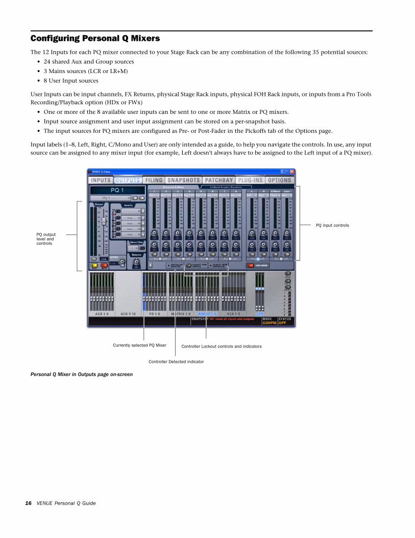
Configuring Personal Q MixersThe 12 Inputs for each PQ mixer connected to your Stage Rack can be any combination of the following 35 potential sources:
• 24 shared Aux and Group sources
• 3 Mains sources (LCR or LR+M)
• 8 User Input sources
User Inputs can be input channels, FX Returns, physical Stage Rack inputs, physical FOH Rack inputs, or inputs from a Pro Tools Recording/Playback option (HDx or FWx)
• One or more of the 8 available user inputs can be sent to one or more Matrix or PQ mixers.
• Input source assignment and user input assignment can be stored on a per-snapshot basis.
• The input sources for PQ mixers are configured as Pre- or Post-Fader in the Pickoffs tab of the Options page.
Input labels (1–8, Left, Right, C/Mono and User) are only intended as a guide, to help you navigate the controls. In use, any input source can be assigned to any mixer input (for example, Left doesn't always have to be assigned to the Left input of a PQ mixer).
Personal Q Mixer in Outputs page on-screen
Currently selected PQ Mixer
PQ output
PQ input controls
level andcontrols
Controller Detected indicator
Controller Lockout controls and indicators
VENUE Personal Q Guide16
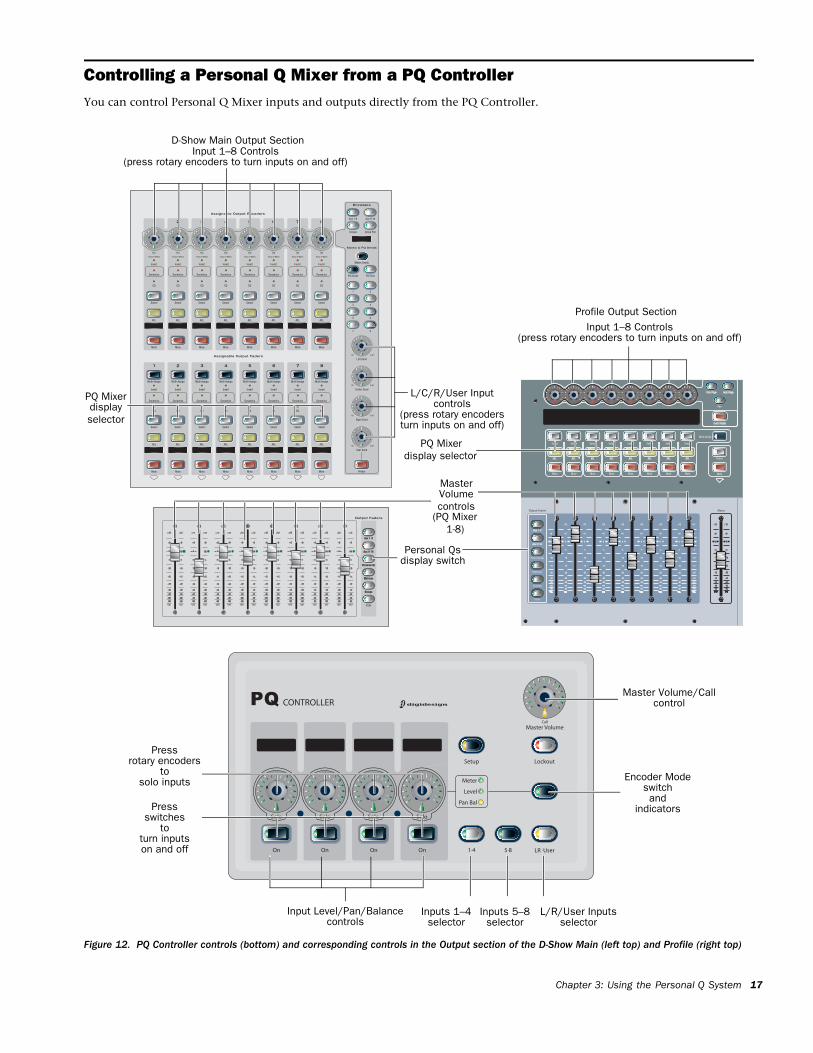
Controlling a Personal Q Mixer from a PQ ControllerYou can control Personal Q Mixer inputs and outputs directly from the PQ Controller.
Figure 12. PQ Controller controls (bottom) and corresponding controls in the Output section of the D-Show Main (left top) and Profile (right top)
Inputs 1–4selector
Inputs 5–8selector
L/R/User Inputsselector
Master Volume/Callcontrol
Encoder Modeswitchand
indicators
Input Level/Pan/Balance
Input 1–8 Controls
Pressrotary encoders
tosolo inputs
L/C/R/User Inputcontrols
MasterVolume
(press rotary encodersturn inputs on and off)
Personal Qsdisplay switch
PQ Mixer
controls
(press rotary encoders to turn inputs on and off)
Pressswitches
toturn inputson and off
(PQ Mixercontrols
1-8)
Input 1–8 Controls(press rotary encoders to turn inputs on and off)
Profile Output Section
D-Show Main Output Section
displayselector
PQ Mixer display selector
Chapter 3: Using the Personal Q System 17
Adjusting PQ Mix Inputs
To control Personal Q Mixer inputs from the PQ Controller:
1 Press any of the Input Selector switches on the PQ Control-ler (1–4, 5–8, or L/R User) to assign the corresponding PQ mixer inputs to the PQ Controller encoders.
2 Press the “On” switches to toggle the corresponding inputs on or off. The switches light to indicate that the correspond-ing inputs are activated.
3 Press the Encoder Mode switch to toggle display of input metering, level, or pan/balance on the PQ Controller encod-ers:
Meter The level of the corresponding PQ mixer input signal is shown on the encoder LEDs. You can adjust level with the en-coders while in this mode.
Level Turn an input encoder to adjust the level for the corre-sponding PQ mixer input. Input level is shown in the encoder display and by an expanding series of encoder LEDs.
Pan/Bal The encoder adjusts the panning of the correspond-ing PQ mixer input across the stereo outputs of the PQ mixer.
Soloing a Personal Q Mixer Input
To solo a PQ mixer input:
Press the encoder knob to toggle solo mode on and off for the corresponding input. All other inputs are temporarily muted when solo is pressed, allowing you to isolate one in-strument in the mix. The Solo indicator LED lights to indicate that the input is soloed.
Adjusting PQ Mixer Output
To control Personal Q mixer output level from the PQ Controller:
Turn the Master Volume encoder. Output level is shown by an expanding series of encoder LEDs.
The Personal Q mixer output Graphic EQ, limiter, polarity, and mute status can be controlled from the console only.
VENUE Personal Q Guide18
Calling the Console from the PQ Controller
To call the console from a Personal Q controller:
Press the Master Volume encoder knob on the controller.
A call message appears on the console display that identifies which PQ Controller is calling. The Call LED on the PQ Con-troller flashes until the message is cleared from the console display.
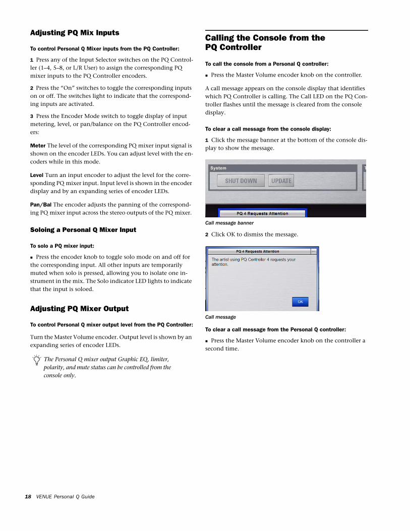
To clear a call message from the console display:
1 Click the message banner at the bottom of the console dis-play to show the message.
2 Click OK to dismiss the message.
To clear a call message from the Personal Q controller:
Press the Master Volume encoder knob on the controller a second time.
Call message banner
Call message
Locking Out PQ Controllers
Lockout From Console
The PQ Controller can be locked out by clicking the on-screen Lockout From Console button in any of the PQ mixers. When this Lockout button is engaged, the PQ controller cannot ad-just PQ mixer controls. The performer using the PQ Controller cannot override this lockout from the controller.
Lockout From Controller
Users can lock their PQ Controllers by pressing the Lockout switch on the controller to prevent inadvertent changes to controller settings. When this is done, the on-screen Lockout From Controller indicator lights in the corresponding PQ mixer. This function does not lock out control of the PQ mixer from the console.
Troubleshooting
PQ Rack Communication
If the PQ Link Fault indicator lights on a connected PQ Rack, or if the PQ Rack does not appear in the Devices tab of the Op-tions page, try the following:
Make sure the length of the PQ Link cable does not exceed 15 ft (4.6 m).
Check power connections to the PQ Rack.
Power cycle the PQ Rack.
Disconnect and reconnect the PQ Link cable from the Stage Rack or from the PQ Rack.
Substitute a different PQ Link cable.
PQ Controller Communication
If a PQ Controller Fault indicator lights on a connected PQ Rack, or if the PQ Controller does not appear in the Devices tab of the Options page, try the following:
Make sure the length of the PQ Controller cable does not ex-ceed 100 ft (30.5 m).
Check power connections to the corresponding PQ Rack.
Power cycle the corresponding PQ Rack.
Disconnect and reconnect the PQ Controller cable from the PQ Rack or from the PQ Controller.
Connect the PQ Controller to a different port on the PQ Rack.
Substitute a different PQ Controller cable.
To test a PQ Controller unit independently, plug the PQ Controller directly into the Personal Q Rack port on the Stage Rack, using the short PQ Link cable. (A PQ Controller cable longer than 15 ft (4.6 m) will not work.)
If the PQ Controller is working properly, it should appear in the Devices tab of the Options page as “PQ 1-1” and properly operate the controls on PQ mixer #1.
Chapter 3: Using the Personal Q System 19
