verification of the performance of the precast concrete … of the performance of the precast...
TRANSCRIPT

Verification of the performance of the precast concrete lining in the Diabolo Tunnel and Liefkenshoek Rail Tunnel
Ken SCHOTTE PhD Student, Researcher Ghent University Ghent, Belgium [email protected]
Hans DE BACKER Professor Ghent University Ghent, Belgium [email protected]
Timothy NUTTENS PhD Student, Researcher Ghent University Ghent, Belgium [email protected]
Alain DE WULF Professor Ghent University Ghent, Belgium [email protected]
Philippe VAN BOGAERT Full Professor Ghent University Ghent, Belgium [email protected]
Summary
During construction of the Diabolo tunnel and the Liefkenshoek railway tunnel in Belgium, strains were monitored in several cross-sections of the precast concrete segmental lining. The obtained measurement data allow evaluating the in situ behaviour of the concrete lining under numerous loading conditions during and after tunnel drive works. The gradual development of strains in the initial stage after ring erection is discussed in relation to the grout loading, hydraulic jack forces and transferred soil and water pressures. Measurement sections below the River Scheldt show that the water level variation, linked to the tides of the North Sea, is clearly depicted in the strain results as a half-daily fluctuation. Results show that despite the rough site conditions, strain monitoring proves a useful verification of tunnel lining performance and an important addition to tunnel design practice.
Keywords: strain monitoring; tunnel; precast concrete segments; ovalisation.
1. Introduction
Since many years, various theoretical models are used to design bored tunnels. In general, a correct identification of the loads acting on the reinforced concrete segments forms an essential step in the design process of the tunnel lining. However, as very few measurement results of actual tunnel lining behaviour are available, estimating the accuracy of the theoretical model output in comparison with the in situ material behaviour remains very difficult. Therefore, the start of recent tunnel works has been an excellent opportunity to accompany the boring process with an experimental monitoring program.
In recent years, several tunnelling projects have been launched in order to extend the Belgian railway network. Among them are the construction of an improved connection to Brussels Airport, known as the Diabolo project, and a new freight connection in the Port of Antwerp, called the Liefkenshoek Rail Link. Generally, during tunnel construction, monitoring is limited to ovalisation of the tunnel lining, where both cited projects also include long term strain monitoring in the precast concrete segments of various tunnel rings. After the first experiences with strain measurements and ovalisation measurements in the Diabolo tunnel, an improved monitoring program is pursued in the Liefkenshoek tunnel, which is the main focus of this paper. The data obtained allows assessing the real-time behaviour of the segments under numerous loading conditions during and after construction of the tunnel lining.
2. Liefkenshoek Rail Link project
The Liefkenshoek Rail Tunnel aims to directly connect the railway freight transport between the left and right bank of the River Scheldt in the Port of Antwerp by 2014. The major part of the 16,2 km long connection, as illustrated in Figure 1, is the twin bored tunnel, shield driven below the River Scheldt and the Port Canal using the mixshield method. Two parallel single-track tunnels with a

length of approximately 6 km were excavated with an internal diameter of 7,3 m. Each tunnel ring is 1,8 m wide and consists of 7 precast concrete elements and a smaller keystone, all of 0,4 m thickness in C50/60 concrete quality. The tunnel alignment is mainly located in tertiary sands, with a maximum water pressure above the tunnel floor of about 40 m and a maximum soil overburden along the tunnel route which equals 33,6 m. In its lower part below the river, the tunnel also passes through tertiary clay. The design had to take account of the presence of an immersed road tunnel established in the 1980s close to the new location. In addition, the existing Beveren tunnel needs to be renovated at full length of 1,2 km. The crossing of the Waasland Canal was foreseen when constructed back in 1973 as this cut and cover tunnel was installed, but it has never been used since.
3. Measurement set-up
During construction of both tunnel tubes, sixteen cross-sections of the tunnel lining were equipped with 18 strain gauges each, distributed across the ring perimeter in circumferential direction, as illustrated in Figure 2. In order to measure the strains in the reinforcement bars, part of the strain gauges were embedded in the segments prior to concrete casting. Strain monitoring started right after assembly of each measurement ring and will continue until delivery of the project. Simultaneously, tunnel ring ovalisation measurements were carried out using a precise Leica HDS 6100 phase scanner with an experimental standard deviation of 0,4 mm. The distribution of the monitored sections along the tunnel axis allows investigating the effect of several local influences such as the maximum water pressure or the presence of cross-passages. In particular the sections include the ones located below the River Scheldt and the Port Canal.
4. Results
Due to the start-up of the data logging process immediately after assembly of the monitored ring, the strain measurements only relate to changes occurring after ring erection. This implies that the reaction of the tunnel ring due to its dead weight and possible assembly stresses is not visible in the results. Strains are measured in tangential direction and discarded of the Poisson effect thanks to the applied half-bridge configuration of the Wheatstone bridge circuit. By convention, tensile stresses
Fig. 1: Schematic longitudinal profile of the Liefkenshoek Rail Link project
= strain gauge
protected strain gauges
Fig. 2: Examples of strain gauge location in lining segments and tunnel ring
correspond to positive strains, compressive stresses to negative values. General results and conclusions on the monitored strains were presented in earlier papers [3]. In this paper we try to focus on some specific phases or events after assembly of the tunnel ring that determine or influence the global strain stabilization.
4.1 Initial hours after ring assembly
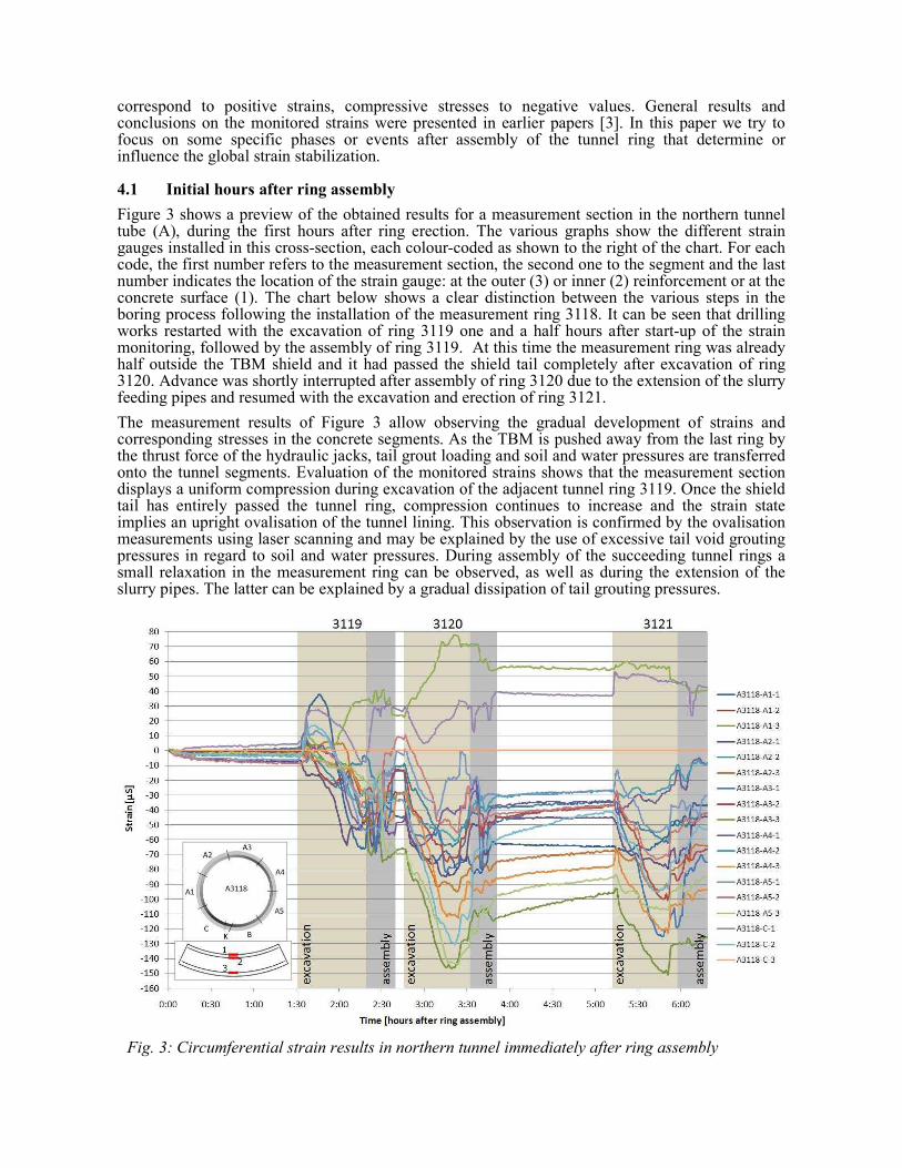
Figure 3 shows a preview of the obtained results for a measurement section in the northern tunnel tube (A), during the first hours after ring erection. The various graphs show the different strain gauges installed in this cross-section, each colour-coded as shown to the right of the chart. For each code, the first number refers to the measurement section, the second one to the segment and the last number indicates the location of the strain gauge: at the outer (3) or inner (2) reinforcement or at the concrete surface (1). The chart below shows a clear distinction between the various steps in the boring process following the installation of the measurement ring 3118. It can be seen that drilling works restarted with the excavation of ring 3119 one and a half hours after start-up of the strain monitoring, followed by the assembly of ring 3119. At this time the measurement ring was already half outside the TBM shield and it had passed the shield tail completely after excavation of ring 3120. Advance was shortly interrupted after assembly of ring 3120 due to the extension of the slurry feeding pipes and resumed with the excavation and erection of ring 3121.
The measurement results of Figure 3 allow observing the gradual development of strains and corresponding stresses in the concrete segments. As the TBM is pushed away from the last ring by the thrust force of the hydraulic jacks, tail grout loading and soil and water pressures are transferred onto the tunnel segments. Evaluation of the monitored strains shows that the measurement section displays a uniform compression during excavation of the adjacent tunnel ring 3119. Once the shield tail has entirely passed the tunnel ring, compression continues to increase and the strain state implies an upright ovalisation of the tunnel lining. This observation is confirmed by the ovalisation measurements using laser scanning and may be explained by the use of excessive tail void grouting pressures in regard to soil and water pressures. During assembly of the succeeding tunnel rings a small relaxation in the measurement ring can be observed, as well as during the extension of the slurry pipes. The latter can be explained by a gradual dissipation of tail grouting pressures.
Fig. 3: Circumferential strain results in northern tunnel immediately after ring assembly

Strain results of the first day following the assembly of ring 3118 show that maximum values of the monitored strains are reached within the progression of the first six rings following the measurement ring and strain results tend to decrease beyond this point. Actually half of the monitored points reach their extreme value during the excavation and erection of the two rings following the installed measurement ring. From these results, it may be presumed that the loads acting on the tunnel segments during the construction process have a substantial influence on the sectional forces occurring in the tunnel lining. Apart from the long term soil and hydrostatic loads, the acting loads during these initial hours after ring erection can be identified as the thrust force of the shield jacks, possible pressure caused by contact with the tail seals and of course the pressure of the tail grouting. These loads may vary according to the position of the tunnel ring or the applied values of fluctuating thrust force and grout pressures. In any case it is reasonable that the construction loads have a dominant role in the segmental loading. The assembly stage can therefore be decisive in the design of the tunnel lining.
4.2 Passage of second TBM
Despite the fact that TBM South was initially launched seven weeks after the northern tunnel drive, it overtook TBM North before the crossing of the River Scheldt due to parallel works on the cross-passages in tunnel North. After thorough maintenance works prior to the river crossing, TBM North followed the leading tunnel drive with a delay of approximately two months. This allowed monitoring strains in the lining of the southern tunnel shaft during passage of the second TBM.
Figure 4 clearly shows that the passage of the adjacent tunnel drive, at a distance of approximately 8 meters next to the southern tunnel, can be observed distinctly in the stabilized strain results of the latter. The effect can already be perceived before passage of the cutterhead and still continues for a short period after the shield tail has passed the equivalent position of the measurement ring. Evaluation of the strain results shows that the excavation of the adjacent tunnel shaft causes a minor horizontal ovalisation of the segmental lining in the leading tunnel. These observations demonstrate the achieved accuracy of the continuous strain monitoring program, as the simultaneous ovalisation measurements using laser scanning did not notice significant alterations during this phase.
Fig. 4: Circumferential strain results in southern tunnel during passage of northern drive

4.3 Construction of cross-passages
For safety reasons, 13 cross-passages and 8 evacuation shafts were constructed parallel with the tunnel drive works at a mean distance of 300 m. All cross-passages had to be excavated within a frozen soil body. The intensive works corresponding with the consecutive construction phases are clearly depicted in the strain development of the concrete tunnel segments. Figure 5 shows strain results from one of the tunnel rings which were actually cut during the construction of cross-passage 03. Even the start of the freezing process to create the frozen soil body can be noticed. After completion of the soil freezing, large and sudden jumps can be observed due to the gradual opening of the tunnel shell for the construction of the cross-passage. The variations are particularly pronounced in tunnel segments A1 and A2, which are oriented to the side of the tunnel which is being cut and partly removed.
The connection galleries to the evacuation shafts were mainly built within treated soil by blocks of cement-bentonite with a low strength. During construction of one of these shafts, an incident occurred where the tunnel sealing was breached and a large amount of mud entered the tunnel. With the help of the strain results of the measurement section nearby the faulty area, the safety of the tunnel worksite could be assured. The incident was clearly registered in the strain monitoring results, but did not significantly affect the stress- and strain state of the tunnel lining.
4.4 Below the River Scheldt
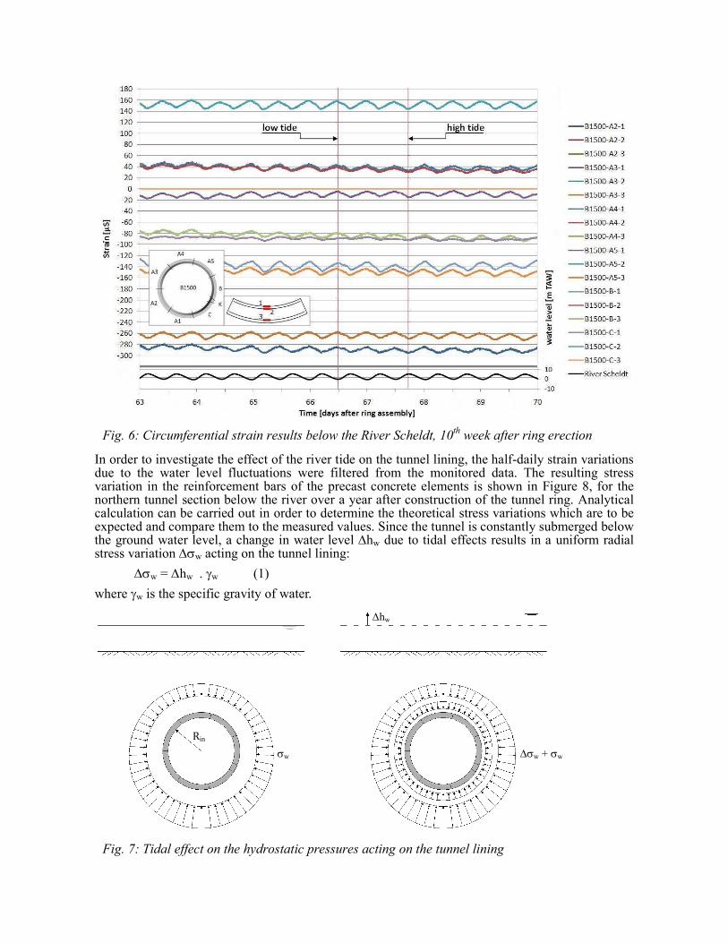
During crossing of the River Scheldt, the water level variation of the river, linked to the tides of the North Sea, had to be taken into account. Every twelve hours the level in the River Scheldt varies between the minimum and maximum values of -1,0 m TAW and +6,5 m TAW, with TAW being the Belgian reference level. This variation has a direct influence on the hydrostatic pressures acting on the tunnel lining. Figure 6 shows the obtained strain results in one of the measurement sections below the river, during the 10
th week after ring erection. At the bottom the half-daily fluctuations of
the water level of the River Scheldt are plotted. The chart shows that despite strains being almost fully stabilized at this time after ring assembly, periodic fluctuations of the tidal level are clearly depicted in the strain results. It can be noticed that high water levels naturally result in a larger uniform compression of the tunnel ring, while compression forces in the lining decrease at low tide.
Fig. 5: Circumferential strain results in southern tunnel near cross-passage 03
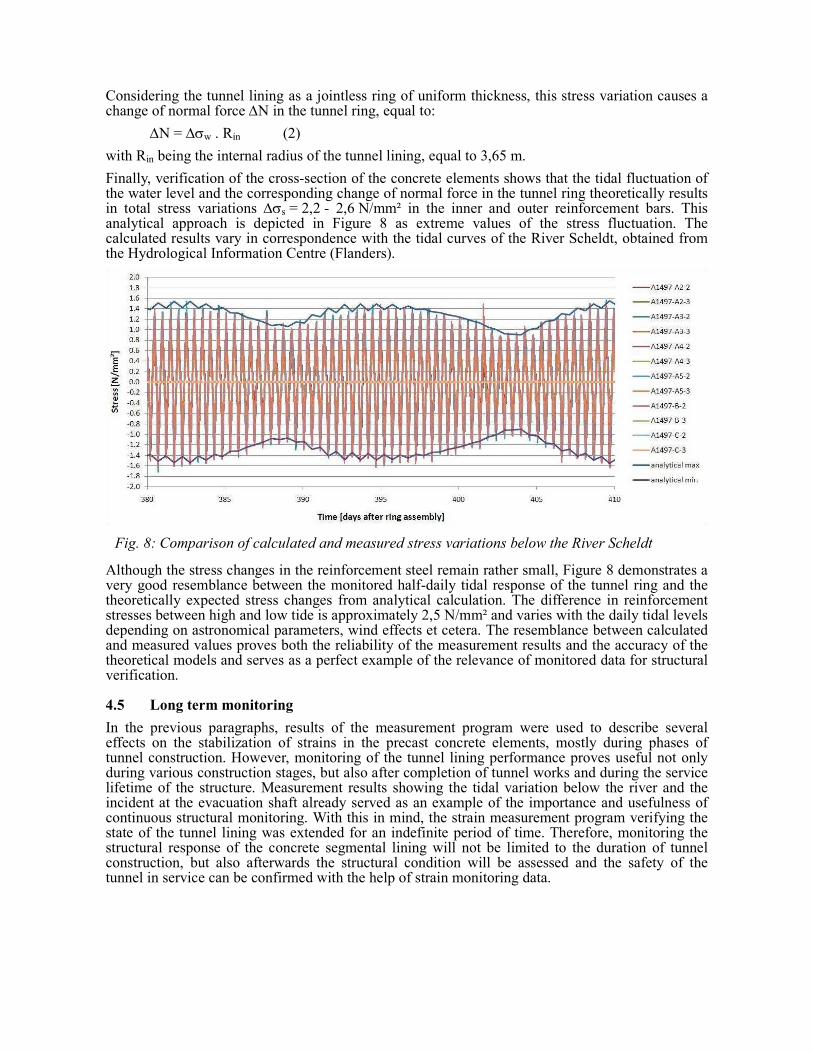
In order to investigate the effect of the river tide on the tunnel lining, the half-daily strain variations due to the water level fluctuations were filtered from the monitored data. The resulting stress variation in the reinforcement bars of the precast concrete elements is shown in Figure 8, for the northern tunnel section below the river over a year after construction of the tunnel ring. Analytical calculation can be carried out in order to determine the theoretical stress variations which are to be expected and compare them to the measured values. Since the tunnel is constantly submerged below the ground water level, a change in water level ∆hw due to tidal effects results in a uniform radial stress variation ∆σw acting on the tunnel lining:
∆σw = ∆hw . γw (1)
where γw is the specific gravity of water.
Fig. 6: Circumferential strain results below the River Scheldt, 10th week after ring erection
Fig. 7: Tidal effect on the hydrostatic pressures acting on the tunnel lining
∆hw
σw ∆σw + σw
Rin
Considering the tunnel lining as a jointless ring of uniform thickness, this stress variation causes a change of normal force ∆N in the tunnel ring, equal to:
∆N = ∆σw . Rin (2)
with Rin being the internal radius of the tunnel lining, equal to 3,65 m.
Finally, verification of the cross-section of the concrete elements shows that the tidal fluctuation of the water level and the corresponding change of normal force in the tunnel ring theoretically results in total stress variations ∆σs = 2,2 - 2,6 N/mm² in the inner and outer reinforcement bars. This analytical approach is depicted in Figure 8 as extreme values of the stress fluctuation. The calculated results vary in correspondence with the tidal curves of the River Scheldt, obtained from the Hydrological Information Centre (Flanders).
Although the stress changes in the reinforcement steel remain rather small, Figure 8 demonstrates a very good resemblance between the monitored half-daily tidal response of the tunnel ring and the theoretically expected stress changes from analytical calculation. The difference in reinforcement stresses between high and low tide is approximately 2,5 N/mm² and varies with the daily tidal levels depending on astronomical parameters, wind effects et cetera. The resemblance between calculated and measured values proves both the reliability of the measurement results and the accuracy of the theoretical models and serves as a perfect example of the relevance of monitored data for structural verification.
4.5 Long term monitoring
In the previous paragraphs, results of the measurement program were used to describe several effects on the stabilization of strains in the precast concrete elements, mostly during phases of tunnel construction. However, monitoring of the tunnel lining performance proves useful not only during various construction stages, but also after completion of tunnel works and during the service lifetime of the structure. Measurement results showing the tidal variation below the river and the incident at the evacuation shaft already served as an example of the importance and usefulness of continuous structural monitoring. With this in mind, the strain measurement program verifying the state of the tunnel lining was extended for an indefinite period of time. Therefore, monitoring the structural response of the concrete segmental lining will not be limited to the duration of tunnel construction, but also afterwards the structural condition will be assessed and the safety of the tunnel in service can be confirmed with the help of strain monitoring data.
Fig. 8: Comparison of calculated and measured stress variations below the River Scheldt

5. Conclusion
Strain measurements allow evaluating the in situ behaviour of the tunnel lining under numerous loading conditions during and after tunnel drive works. The gradual development of strains in the first hours after ring assembly showed that loads acting on the tunnel segments during the construction process can have a substantial influence on the sectional forces in the tunnel lining. Therefore construction loads such as the thrust force of the shield jacks, possible pressure caused by contact with the tail seals and the pressure of the tail grouting can be decisive in the design of the tunnel lining.
Furthermore the influence of the construction of cross-passages and the opening of evacuation shafts on adjacent measurement sections was discussed. It could be noticed that the segmental lining of the leading tunnel shaft experienced minor changes in strain state during passing of the second TBM. The excavation of the adjacent tunnel shaft caused a small horizontal ovalisation of the segmental lining in the leading tunnel. Finally, measurement sections below the River Scheldt show that the water level variation, linked to the tides of the North Sea, was clearly depicted in the strain results as a half-daily fluctuation. Measurement results showed a very good resemblance with the analytical calculation of the expected stress variations of the reinforcement steel in the tunnel elements.
Results show that despite rough site conditions, strain monitoring proves a useful verification of tunnel lining performance and an important addition to tunnel design practice. Design of the precast concrete tunnel lining should not focus exclusively to parameters of the surrounding soil, the groundwater situation or loads on the surface level. It should also study the effect of loads during ring erection, advance of the TBM and tail grouting, as obtained measurement results have shown that these construction parameters may constitute a dominant factor in the tunnel lining design.
Further research will concentrate on the validation of the various theoretical models for tunnel design in comparison with the monitored in situ behaviour. An optimization of the design is pursued and, if necessary, an adjustment of the existing theories will be made in search of the perfect balance between structural stability and economic design.
6. References
[1] SCHOTTE K., DE BACKER H., NUTTENS T., DE WULF A. and VAN BOGAERT PH., “Strain gauge measurements during the assembly of the Diabolo tunnel”, IABSE Venice Symposium Report, Vol. 97, 2010, pp. 626-627.
[2] BOXHEIMER S., and MIGNON J., “Half way of construction of the Liefkenshoek Rail Tunnel”, Tunnel, Vol. 3/2011, 2011, pp. 41-48.
[3] MASHIMO H., ISHIMURA T. and MORIMOTO S., “Evaluation of construction loads for the design of shield tunnel segments through field measurements”, Proceedings of the World Tunnel Congress, Helsinki, Finland, 2011, pp. 32-33.
[4] SCHOTTE K., DE BACKER H., NUTTENS T., DE WULF A. and VAN BOGAERT PH., “Monitoring strains in the Liefkenshoek railway tunnel”, Proceedings of the World Tunnel Congress, Helsinki, Finland, 2011, pp. 254-255.