verification of welding simulations with · pdf fileworkshop: current state and future of...
TRANSCRIPT

Verification of Welding Simulations with Measurement
Workshop: Current State and Future of Neutron Stress Diffractometers
January 10-12, 2012, Sydney (Lucas Heights)
Our Major Collaborators in Welding Simulations
• British Energy – EDF
• European Network on Neutron Techniques (NeT) – AREVA– Rolls-Royce– SERCO– Etc…..
Developing expertise for future power generation technology including Gen IV

1
-ABAQUS Weld Simulation Model - Thermal Analysis- Mechanical Analysis
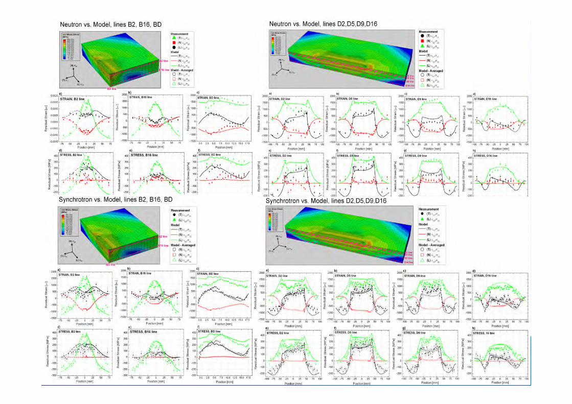
- Neutron Diffraction- Synchrotron Diffraction- X-ray diffraction- Contour deflections - Deep hole drilling
Process of determining and verifying residual stress using simulation and measurement
FE Modelling
Verification
Co dependant

NeT Task Group work –round robins
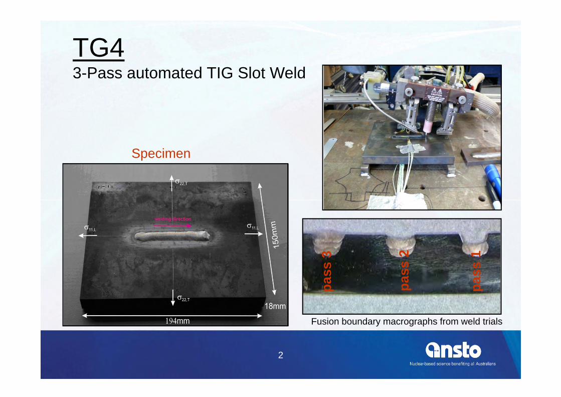
• TG4– 3 pass weld– 316L (Austenitic -no phase transformation)
• TG5– Autogenous weld– AS508 (Ferritic -phase transformation)
2
TG43-Pass automated TIG Slot Weld
Specimen
Fusion boundary macrographs from weld trials
pass
1
pass
2
pass
3
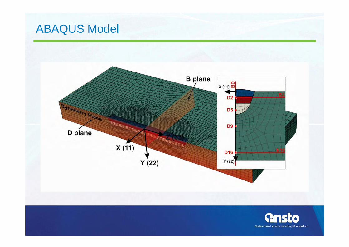
ABAQUS Model

Welding Parameters -for each pass
• Volts• Amps• Run speed• Weaving?• Wire feed rate• Interpass temperature
5
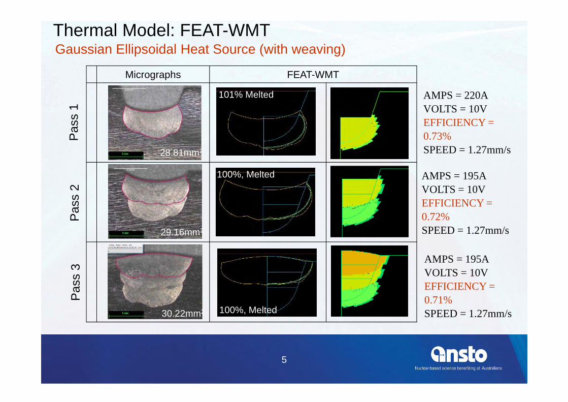
Micrographs FEAT-WMTP
ass
1P
ass
2P
ass
3101% Melted
100%, Melted
100%, Melted
AMPS = 220AVOLTS = 10VEFFICIENCY = 0.73%SPEED = 1.27mm/s
AMPS = 195AVOLTS = 10VEFFICIENCY = 0.72%SPEED = 1.27mm/s
AMPS = 195AVOLTS = 10VEFFICIENCY = 0.71%SPEED = 1.27mm/s
28.81mm2
Thermal Model: FEAT-WMTGaussian Ellipsoidal Heat Source (with weaving)
29.16mm2
30.22mm2
7
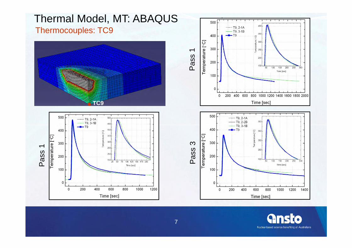
Thermal Model, MT: ABAQUSThermocouples: TC9
TC9
Pas
s 1
Pas
s 1
Pas
s 3

Welding Thermal Simulation (~18 hours)
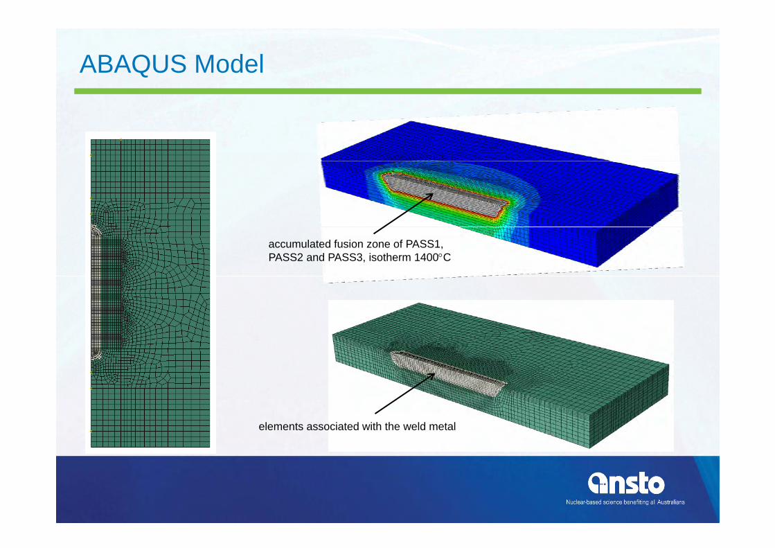
accumulated fusion zone of PASS1, PASS2 and PASS3, isotherm 1400C
elements associated with the weld metal
ABAQUS Model

Mechanical Analysis -Material Properties
• Elastic Modulus
• Thermal Expansion
• Strain Hardening properties
• Annealing temperature
all temperature dependant!

Material Testing• Cyclic Hardening
– 20, 200, 400, 600, 700, 800 °C
600deg 2.5%strain 0.04%/s
-400
-300
-200
-100
0
100
200
300
400
-1.5 -1 -0.5 0 0.5 1 1.5
Strain (%)
Stre
ss (M
Pa)
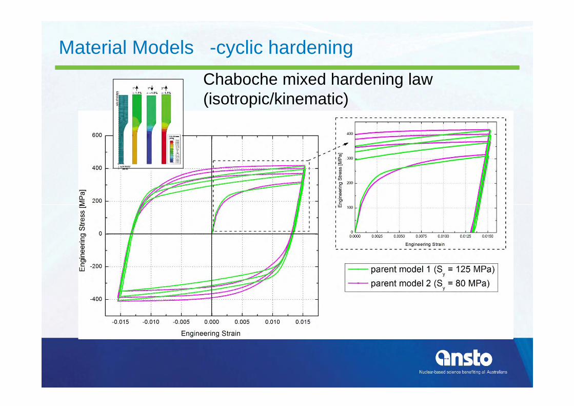
Material Models -cyclic hardeningChaboche mixed hardening law (isotropic/kinematic)
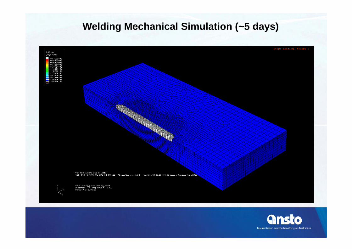
Welding Mechanical Simulation (~5 days)


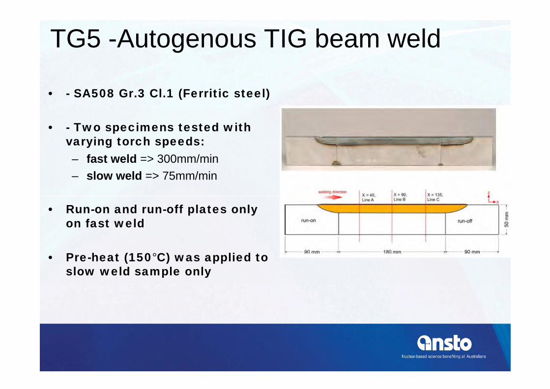
TG5 -Autogenous TIG beam weld
• - SA508 Gr.3 Cl.1 (Ferritic steel)
• - Two specimens tested with varying torch speeds:– fast weld => 300mm/min– slow weld => 75mm/min
• Run-on and run-off plates only on fast weld
• Pre-heat (150°C) was applied to slow weld sample only

2D Finite Element Model
Slow WeldFast Weld

Slow WeldFast Weld
Thermal Analysis - Fusion Zone
observation FEAT prediction observation FEAT prediction

(1) Isothermal Phase Nucleation
S(X)Q/RT)(ΔT
)Ni,Cr,Mo,GF(C,Mn,Si,τ(X,T) n
exp
10-1 100 101 102 103 104 105 106300
400
500
600
700
800
900
M
A P
F
B
Tem
pera
ture
[C]
Time [sec]
- Semi-empirical formulae developed by Li et al. (1998), modified from Kirkaldy and Venugopalan (1984).
TTT diagram
- F is a function to the steel composition and the ASTM grain sizenumber G, ΔT is the amount of undercooling, Q is the activationenergy for the diffusion reaction, R is the gas constant, n is anempirical constant based on the effective diffusion mechanism, andS(X) is a sigmoidal function defining the reaction rate.
- The model describes the time (τ) required for a given transformation to reach a fraction of completion X at constant temperature T.
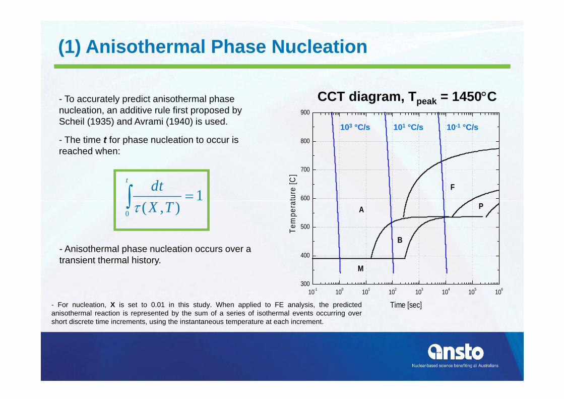
(1) Anisothermal Phase Nucleation
10-1 100 101 102 103 104 105 106300
400
500
600
700
800
900
M
A P
F
B
Tem
pera
ture
[C]
Time [sec]
103 °C/s 101 °C/s 10-1 °C/s
1),(0
t
TXdt
CCT diagram, Tpeak = 1450C- To accurately predict anisothermal phase nucleation, an additive rule first proposed by Scheil (1935) and Avrami (1940) is used.
- The time t for phase nucleation to occur is reached when:
- For nucleation, X is set to 0.01 in this study. When applied to FE analysis, the predictedanisothermal reaction is represented by the sum of a series of isothermal events occurring overshort discrete time increments, using the instantaneous temperature at each increment.
- Anisothermal phase nucleation occurs over a transient thermal history.

(2) Austenite Grain Growth
10-1 100 101 102 103 104 105 106300
400
500
600
700
800
900
M
A P
F
B
Tem
pera
ture
[C]
Time [sec]
TetADD /6930040
4
- Empirical formula developed by Ikawa et al. (1977) describes the austenite growth kinetics in ferritic steels using the following formulation for a given increment of time Δt:
- D, D0 represent the final and initial austenite grain size in mm, respectively. The approach was foundto be consistent for a wide range of ferritic steels, and assumed an initial grain diameter of 0.015 mm at1000 C. The ASTM grain size number is determined from the predicted diameter and this is updated inthe nucleation equation.
- Can result in significant delay in phase nucleation, depending on peak temperature
1510969.2 A
Constant Grain Size Variable Grain Size
CCT diagram, Tpeak = 1450C

(3) Phase Growth Kinetics
SiCoMoCrNiMnCM S 5.7105.71.127.174.30423539
- Martensitic growth kinetics is assumed instantaneous once temperature drops below the martensite start temperature (Ms) based on Kung and Rayment (1982):
- Diffusional growth kinetics (bainite, ferrite, pearlite) are predicted using a modified Leblond and Devaux (1984) formalism:
t
t TTdtz
0),01.0(),00.1(
- Original implementation required fit to empirical data, modification allows for growth to be based on sigmoidal growth assumption from isotropic kinetics.
total time (isothermal) from phase nucleation to completion (100%)
- τ (1.00, T) is the time when 100% of thephase is created, τ(0.01, T) is the time of phasenucleation

Microstructure - Observation
Fast Weld Slow Weld

Microstructure - Predictions
Fast Weld Slow Weld
ferrite/austeniteon heating
bainite/martensiteon cooling
ferrite/austeniteon heating
bainite/martensiteon cooling
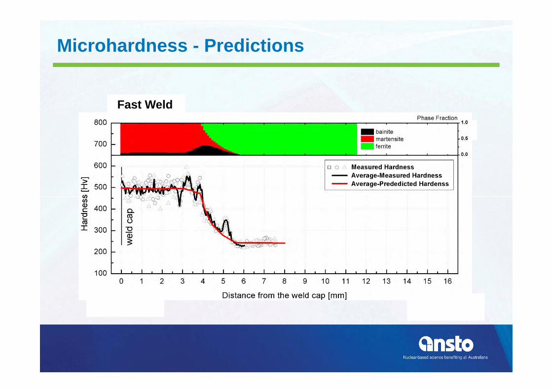
Microhardness - Predictions
Fast Weld
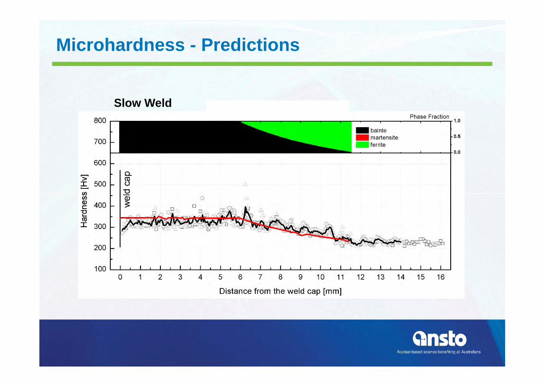
Slow Weld
Microhardness - Predictions

3D Finite Element Model

TG5 3D Slow - Thermal Analysis
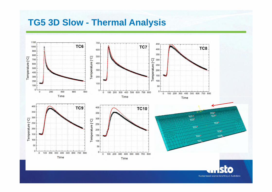
TG5 3D Slow - Thermal Analysis
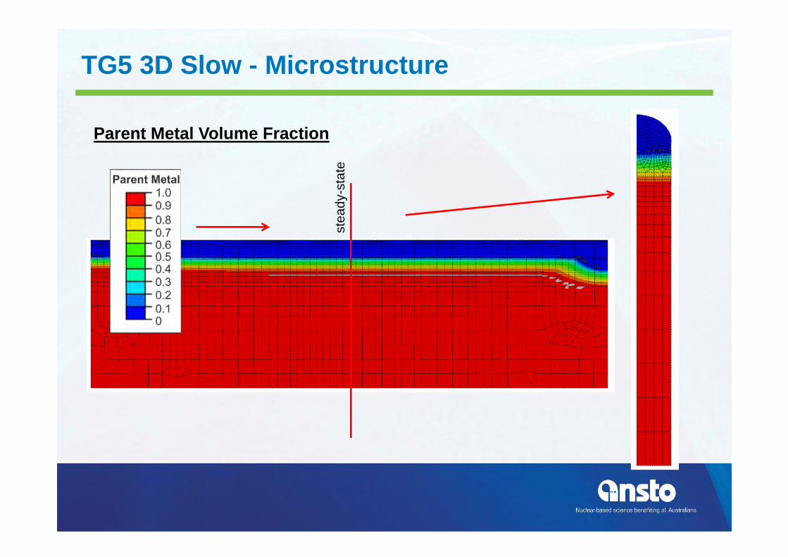
TG5 3D Slow - Microstructure
Parent Metal Volume Fraction
stea
dy-s
tate

TG5 3D Slow - Microstructure
Martensite Volume Fraction
stea
dy-s
tate

Bainite Volume Fraction
stea
dy-s
tate
TG5 3D Slow - Microstructure

TG5 3D Slow - Residual Stress
No Specific Phase Yielding included !!!
- coupled analysis- SA508 material properties only
- We have more work to do!!- But how would you know without
the measurements
Why all the effort?
• Techniques developed and verified on simple geometries can be used on more complex “real” welds

Weld Simulation Case Study: Stress Corrosion Cracking in Pressurised Water Reactor Welds
• Since 2000, 19 cracks found at dissimilar metal welds• Engineering solution is full structural weld overlays• Structural Integrity assessment needs weld stresses• ANSTO working with Nuclear Regulatory Commission (US)
and British Energy-EDF (UK) to develop validated weld modelling of dissimilar metal welds

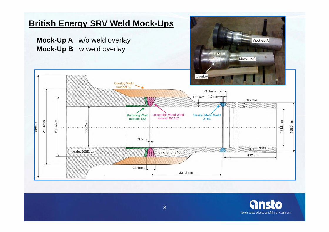
Mock-up of dissimilar metal weld on a pressurising safety relief line
3
British Energy SRV Weld Mock-Ups
Mock-Up A w/o weld overlayMock-Up B w weld overlay

1
Modelling of Nuclear Dissimilar Weld Overlays OVERLAY: 543 passes
PIPE WELD: 15 passes
DISSIMILAR WELD: 46 passes
BUTTERING: 94 passes
Inconel 82/182
Alloy 508 Cl 3Inconel 52
Alloy 316
Full axi-symmetric model of instrumented mock up contains 598 weld passes in four different alloys
INSTRUMENTED MOCK UP

20
Fusion Boundary, Thermal ModelDissimilar Metal Weld (DMW)
Accumulated fusion boundary (1400˚C isotherm)
of 46 passes, Inconel 82/182
nozzlesafe-endbuttering

3
S33, Hoop Residual Stresses
DISSIMILAR WELD: Development of Residual Stresses

Hoop stress
Residual Stress, Mechanical ModelWeld Overlay

Residual Stress, Mechanical ModelWeld Overlay

Final comments
• Simulations without verification are hard to publish
• Recently even simulations with verification are hard to publish
• We need to develop further• Damage mechanics .. (Verified??)