verify this is the correct version before use · ams mechanical design lead engineer, lmso paul...
TRANSCRIPT

JSC 29789
Project Technical Requirements Specification for the Alpha Magnetic Spectrometer-02 (AMS-02) Payload Integration Hardware (PIH) Space and Life Sciences Directorate Mission Planning and Integration Office
Verify this is the correct version before use For correct version go to:
Revision A March 17, 2003
National Aeronautics and Space Administration Lyndon B. Johnson Space Center Houston, Texas 77058

JSC 29789
i
PROJECT TECHNICAL REQUIREMENTS SPECIFICATION FOR THE
ALPHA MAGNETIC SPECTROMETER-02 (AMS-02) PAYLOAD INTEGRATION HARDWARE (PIH)
Prepared By:
Michael Fohey AMS Payload Engineer, LMSO
Reviewed By:
Ross Harold AMS Mechanical Design Lead Engineer, LMSO Paul Nemeth AMS Avionics Lead Engineer, LMSO Trent Martin AMS Deputy Project Manager, LMSO
Approved By:
Ken Bollweg AMS Project Manager, LMSO James Bates AMS Mission Manager, Mission Planning & Integration Office, NASA/JSC
Vincent Watkins Chief, GFE Assurance Branch, NASA/JSC

JSC 29789
ii
PAGE __1__ OF __1___ DOCUMENT CHANGE/REVISION LOG
CHANGE/ REVISION DATE DESCRIPTION OF CHANGE PAGES
AFFECTED
Basic December, 2002
Initial release for baseline All
A March, 2003 Revised to incorporate comments from SR&QA

JSC 29789
iii
TABLE OF CONTENTS
1. INTRODUCTION...................................................................................................................29
1.1 PURPOSE AND SCOPE...............................................................................................29
1.2 RESPONSIBILITY AND CHANGE AUTHORITY....................................................30 1.2.1 NASA-JSC MPIO Responsibilities .......................................................................30 1.2.2 Change Authority...................................................................................................32
2. APPLICABLE AND REFERENCE DOCUMENTS........................................................34
2.1 APPLICABLE DOCUMENTS .....................................................................................34
2.2 ORDER OF PRECEDENCE ........................................................................................36
3. REQUIREMENTS...............................................................................................................38
3.1 AMS-02 PIH SYSTEM DEFINITION..........................................................................38 3.1.1 AMS-02 PIH Equipment........................................................................................41 3.1.2 AMS-02 Interface Description...............................................................................45
3.2 CHARACTERISTICS ..................................................................................................53 3.2.1 Functional Performance .........................................................................................53 3.2.2 Physical ..................................................................................................................54 3.2.3 Environmental........................................................................................................55 3.2.4 Reliability...............................................................................................................61 3.2.5 Maintainability.......................................................................................................62 3.2.6 Transportability......................................................................................................62
3.3 DESIGN AND CONSTRUCTION ...............................................................................62 3.3.1 Materials, processes and parts ...............................................................................62 3.3.2 Structural Design ...................................................................................................64 3.3.3 Nameplates and Product Marking..........................................................................64 3.3.4 Workmanship.........................................................................................................64 3.3.5 Human Engineering ...............................................................................................65 3.3.6 Safety .....................................................................................................................65 3.3.7 Lifetime..................................................................................................................65 3.3.8 Security ..................................................................................................................65
3.4 LOGISTICS ...................................................................................................................65 3.4.1 Maintenance...........................................................................................................66 3.4.2 Supply ....................................................................................................................66 3.4.3 Spares.....................................................................................................................66
4. PREPARATION FOR DELIVERY...................................................................................67
4.1 PACKAGING LEVELS AND METHODS ..................................................................67
4.2 PACKAGING DESIGN VERIFICATION/QUALIFICATION ...................................67
4.3 MILITARY TRANSPORTATION PROCEDURES DOCUMENTATION AND REPORTS .....................................................................................................................67
4.4 MARKING FOR SHIPMENT.......................................................................................67

JSC 29789
iv
5. VERIFICATION..................................................................................................................68

JSC 29789
v
APPENDICES Appendix A Acronyms and Abbreviations

JSC 29789
vi
LIST OF FIGURES Figure Page Figure 3.1-1 The AMS-02 System...............................................................................................38 Figure 3.1-2 AMS-02 Payload Assembly (View 1 of 4) .............................................................39 Figure 3.1-3 AMS-02 Payload Assembly (View 2 of 4) .............................................................39 Figure 3.1-4 AMS-02 Payload Assembly (View 3 of 4) .............................................................40 Figure 3.1-5 AMS-02 Payload Assembly (View 4 of 4) .............................................................40 Figure 3.1.1.1-1 AMS-02 Superconducting Magnet with Vacuum Case....................................42 Figure 3.1.2-1 USS-02 Exploded View ......................................................................................46 Figure 3.1.2.1-1 AMS-02 Payload STS Interfaces ......................................................................47 Figure 3.1.2.1-2 Cross Section of the AMS-02 in the Shuttle Payload Bay................................48 Figure 3.1.2.1-3 AMS-02/Pad and STS Avionics Interfaces Diagram........................................49 Figure 3.1.2.2-1 AMS-02 Payload ISS Interfaces .......................................................................50 Figure 3.1.2.2-2 AMS-02 Payload Attached to the Active PAS on the S3 Inboard PAS Site ....51 Figure 3.1.2.2-3 AMS-02/ISS Avionics Interconnect Diagram ..................................................52

JSC 29789
vii
TABLES
Table Page Table 1.2.1-2 – NASA STS/ISS Provided Flight Hardware..........................................................31 Table 1.2.1-3 – MPIO/LMSO Provided GSE and GHE................................................................32 Table 3.2.2.1-1 – Estimated CG of the AMS-02 Payload in the PAS, S3, and S0 Coordinate
Systems ........................................................................................................54 Table 3.2.2.1-2 – Location of the AMS-02 Origin with respect to the PAS, S3, and S0 .................
Coordinate Systems...........................................................................................54 Table 3.2.2.2 – Dimensions of the AMS-02 Payload ....................................................................55

JSC 29789
29
1. INTRODUCTION
In this Project Technical Requirements Specification (PTRS) “AMS” will refer to the total complement of activities, hardware, software, test, integration and operation of the Alpha Magnetic Spectrometer – 02 (AMS-02). The flight hardware is referred to as the “AMS Payload” and is comprised of two parts: the “AMS Experiment” provided by the International AMS Experiment Collaboration and the “AMS Payload Integration Hardware (PIH)” provided by the Mission Planning and Integration Office (MPIO) of the Space and Life Sciences Directorate with the support of Lockheed Martin Space Operations (LMSO). This PTRS specifically covers the PIH provided by MPIO/LMSO.
The AMS Experiment is a state-of-the-art particle physics detector containing a large, cryogenic superfluid helium superconducting magnet (Cryomag) that will be designed, constructed, tested and operated by an international team organized under United States Department of Energy (DOE) sponsorship. The AMS Experiment will use the unique environment of space to advance knowledge of the universe and potentially lead to a clearer understanding of the universe’s origin. Specifically, the science objectives of the AMS are to search for antimatter (anti-helium and anti-carbon) in space, to search for dark matter (90% of the missing matter in the universe) and to study astrophysics (to understand Cosmic Ray propagation and confinement time in the Galaxy).
The AMS-02 is an unpressurized, full truss mounted payload that will utilize a Cryomag with planes of detectors above, inside and below the magnet. Electrically charged particles that pass through the magnetic field will curve. Charged particles made of matter will curve one way, and those of antimatter will curve the opposite way. The positions of the charged particles will be electronically recorded. Physicists will be able to study the trajectory of curvature and determine the charge of the particles from the direction of curvature. They will also be able to determine the mass of the particles from the amount of curvature. They will then be able to tell whether it was matter or antimatter.
1.1 PURPOSE AND SCOPE
This specification defines the technical requirements for the PIH and related ground support equipment delivered to the International Space Station Program by AMS-02 Project. The verification requirements for the AMS-02 Payload are contained in the Alpha Magnetic

JSC 29789
30
Spectrometer (AMS–02) Attached Payload Hardware Interface Control Document (ICD), SSP 57213.
The following definitions differentiate between requirements and other statements.
• Shall: This is the only verb used for the binding requirements.
• Should/May: These verbs are used for stating non-mandatory goals.
• Will: This verb is used for stating facts or declaration of purpose.
1.2 RESPONSIBILITY AND CHANGE AUTHORITY
The PTRS establishes the overall project technical requirements for the AMS-02 elements that are the responsibility of MPIO and LMSO, and establishes safety requirements for all of the AMS-02 PIH elements.
The responsibility for assuring definition, control, implementation, and accomplishment of the activities identified in this document is vested with the MPIO/LMSO for all AMS PIH and with the Massachusetts Institute of Technology (MIT) for the AMS Experiment.
1.2.1 NASA-JSC MPIO Responsibilities
MPIO/LMSO is responsible for providing all AMS payload integration activities consisting of flight and ground safety, analytical and physical integration, development of AMS payload integration hardware (PIH) [i.e. Unique Support Structure – 02 (USS-02), Cryomagnet Vacuum Case (VC), Digital Data Recording System – 02 (DDRS-02) etc.], development of AMS Payload software requirements, and AMS Payload hardware/software verification. In addition, MPIO/LMSO will provide Ground Support Equipment (GSE) and Ground Handling Equipment (GHE) to support ground processing for the USS-02, VC and DDRS-02. Table 1.2.1-1 details the flight hardware items that are the responsibility of MPIO/LMSO; Table 1.2.1-2 lists the flight hardware provided by NASA’s Space Transportation System (STS) and ISS Programs that will be integrated by MPIO/LMSO; and Table 1.2.1-3 lists the GSE and GHE for which MPIO/LMSO is responsible.
All activities and deliverables will be performed in accordance with the AMS-02 Master Schedule, which is updated periodically by the MPIO. MPIO/LMSO is responsible for identifying to MIT all integration issues that may affect MIT responsibilities and will include a plan to resolve the issues.

JSC 29789
31
TABLE 1.2.1-1 – MPIO/LMSO PROVIDED FLIGHT HARDWARE
ITEM UNITS
Cryomagnet Vacuum Case (VC) (Flight Article) 1
Meteoroid and Orbital Debris (M/OD) shields at least 2
Payload Attach System (PAS) (Passive Half) 1
EVA Interface Panel (Interface to UMA) 1
Interface Panel A (Interface to ROEU) 1
Cabling from interface panels to J-Crate and PDB as required
Digital Data Recording System (DDRS–02) and associated cabling/interface cards 1
Thermal Blankets TBD-2
Unique Support Structure-02 (USS-02) 1
Brackets to interface the EBCS, PVGF, ROEU/PDA, and UMA to the USS-02
as Required
TABLE 1.2.1-2 – NASA STS/ISS PROVIDED FLIGHT HARDWARE
ITEM UNITS
External Berthing Cue System (EBCS) w/cables 1
EVA (Extravehicular Activity) handrails 10 or less
Flight Releasable Grapple Fixture (FRGF) 1
Portable Foot Restraints (PFR) Worksite Interface (WIF) 1
Power Video Grapple Fixture (PVGF) w/cables 1
Remotely Operated Electrical Umbilical/Payload Disconnect Assembly (ROEU/PDA) w/cables
1
Umbilical Mechanism Assembly (UMA) (Passive Half) w/cables 1

JSC 29789
32
TABLE 1.2.1-3 – MPIO/LMSO PROVIDED GSE AND GHE
ITEMS UNITS
VC Structural Test Article (STA) 1
Primary Support Stand (PSS) 1
Lower USS Support Fixture 1
Primary Lifting Fixture 1
Multi-purpose Lifting Fixture 2
Intermediate Support Fixtures 4
USS-02 Assembly Fixture 1
Special Test Equipment (STE) for Structural Testing Multiple
Neutral Buoyancy Laboratory (NBL) Mockup 1
VC/Magnet Shipping Fixture 2
MPIO/LMSO will convene and conduct a Preliminary Design Review (PDR) and a Critical Design Review (CDR) for the integration activities and hardware developed by the MPIO. MPIO/LMSO will support International Space Station Program (ISSP) and Space Shuttle Program (SSP) meetings and reviews as required to support the AMS integration process. The meetings and reviews will include but are not limited to the following:
• Cargo Integration Review (CIR)
• Payload Flight Safety Reviews
• Payload Ground Safety Reviews
• Flight Planning and Stowage Reviews (FPSR)
• Verification Acceptance Review (VAR)
• Flight Operations Review (FOR)
• Flight Readiness Review (FRR)
• Space Shuttle Integrated Product Team (IPT) meetings
• Launch Package Manager’s IPT meetings
1.2.2 Change Authority

JSC 29789
33
This document is prepared in accordance with EA-WI-023, Project Management of GFE Flight Projects, paragraph 7.5.1.2. The responsibility for the development of this document lies with the Space and Life Sciences Directorate MPIO. Change authority will be the AMS Configuration Control Panel (CCP).
Configuration control will be initiated upon signature approval. MPIO will maintain configuration control of this document in accordance with JSC 27542, “Alpha Magnetic Spectrometer (AMS) Configuration Management Plan.” All proposed changes to the PTRS shall be submitted by MPIO Change Request/Directive (CR/DIR) and jointly approved by the MPIO and MIT.

JSC 29789
34
2. APPLICABLE AND REFERENCE DOCUMENTS
2.1 APPLICABLE DOCUMENTS
The following documents, of the exact issue and revision shown, form a part of this specification to the extent specified herein. The current document issue in effect on the date of approval of this PTRS shall apply unless otherwise noted. A notation of “Current issue” after date of approval indicates all future changes and revisions are applicable to the AMS project as stated above.
DOCUMENT NUMBER REVISION / RELEASE DATE DOCUMENT TITLE
IPC 2221 Basic Amendment-1 02/01/98 Jan 2000
Generic Standard on Printed Board Design
IPC 6011 Basic 02/01/98
Generic Performance Specification for Printed Boards
IPC 6012 A Amendment-1 10/99 Jul 2000
Qualification and Performance for Rigid Printed Boards
JPD 5335.1 C 1/16/01
JSC Quality Management System (QMS)
JSC 27301 D 02/14/02
Materials Control Plan for JSC Flight Hardware
JSC 27622 Project Management Plan - Early Communications System
JSC 29095 Part I & II (ICD-C)
Basic Part I – TBD Part II – 12/2001
Alpha Magnetic Spectrometer - 02 (AMS-02) Experiment/Payload Integration Hardware (PIH) Interfaces
JSC 61360 A 07/98
Engineering Directorate Certified Parts Approval Process
JSC-SPEC-M1 B Nov 1985
Specification Marking, Identification, and Inspection
MSFC-HDBK-527/JSC-09604
F 9/30/88
Materials Selection List for Space Hardware Systems
NASA-STD-8739.1 Basic 8/6/99
Workmanship Standard for Staking and Conformal Coating of Printed Wiring Boards and Electronic Assemblies
NASA-STD-8739.2 Basic 08/31/1999
Workmanship Standard for Surface Mount Technology

JSC 29789
35
DOCUMENT NUMBER REVISION / RELEASE DATE DOCUMENT TITLE
NASA-STD-8739.3 Basic Chg 2 12/15/97 01/18/01
Soldered Electrical Connections
NASA-STD-8739.4 Basic 2/9/98
Crimping, Interconnecting Cables, Harnesses, and Wiring
NASA-STD-8739.5 Basic 02/09/98
Fiber Optic Terminations, Cable Assemblies, and Installation
NHB 6000.1 D 09/30/90
Requirements for Packaging, Handling and Transportation for Aeronautical and Space System Equipment and Associated Components
NSTS 21000-IDD-ISS
A CPN 27 2/18/98 12/07/01
International Space Station Interface Definition Document
NSTS/AMS ICD-A-TBD
Basic TBD
Shuttle Orbiter/AMS-02 Cargo Element Interfaces
SE-M-0096 A 06/28/82
General Specification For Materials and Processes Requirements for JSC Controlled Payloads,
SN-C-0005 D Chg 7 07/20/98 06/27/01
Space Shuttle Contamination Control Requirements
SSP 30233 F 07/16/99
Space Station Requirements for Materials and Processes
SSP 30243 G 7/32/02
Space Station Requirements for Electromagnetic Compatibility
SSP 30312 H 11/22/99
Electrical, Electronic, and Electromechanical (EEE) andMechanical Parts Management and Implementation Plan for Space Station Program
SSP 57003 Basic IRN-0001 11/18/99 06/21/01
Attached Payload Interface Requirements Document
SSP 57213 Basic TBD
Alpha Magnetic Spectrometer (AMS-02) Attached Payload Hardware Interface Control Document
DODR-4500.32R Vol. 1, Vol. 2 3/15/87 2/15/87
Military Standard Transportation and Movement Procedures

JSC 29789
36
DOCUMENT NUMBER REVISION / RELEASE DATE DOCUMENT TITLE
MIL-STD-129 N 5/15/97
Standard Practice for Military Marking
MIL-STD-130 K 1/15/00
Identification Marking of U.S. Military Property
MIL-STD-2073-1 D Notice 1 12/15/99 05/10/02
Standard Practice for Military Packaging
ANSI/ESD S20.20-1999
1999 Standard for the Development of an ESD Control Program
2.2 Reference Documents The following are reference documents utilized in the development of this specification. These documents do not form a part of this specification, and are not controlled by their reference herein.
DOCUMENT NUMBER REVISION / RELEASE DATE DOCUMENT TITLE
EA-WI-023 C 1/17/03
Project Management of GFE Flight Projects
JSC-27542 / LMES-32218
Basic 01/28/97
Alpha Magnetic Spectrometer Configuration Management Plan
SSP 57113 Basic TBD
Payload Integration Agreement For Alpha Magnetic Spectrometer (AMS)
SSP 57113A Basic TBD
Payload Integration Agreement Increment Addendum For Alpha Magnetic Spectrometer – 02 (AMS-02)
SSP 57313 Basic TBD
Alpha Magnetic Spectrometer (AMS) Software Interface Control Document
2.2 ORDER OF PRECEDENCE
In the event of a conflict between the text of this specification and an applicable document cited herein, the text of this specification takes precedence.
All specifications, standards, exhibits, drawings or other documents that are invoked as “applicable” in this specification are incorporated as cited. All documents that are referred to by an applicable document are considered to be for guidance and information only, with the

JSC 29789
37
exception of ICDs, which shall have their applicable documents considered to be incorporated as cited.

JSC 29789
38
3. REQUIREMENTS
3.1 AMS-02 PIH SYSTEM DEFINITION
The AMS-02 payload integration hardware (PIH) provides the required structural, electrical, and C&DH interfaces between the components of the AMS-02 experiment and 1) the STS for transfer to and from orbit, and 2) the ISS during its on-orbit operational lifetime. The major subsystems of the AMS-02 which are addressed in this PTRS are the USS-02 (which includes the integral Vacuum Case for the superfluid helium superconducting Cryomagnet), passive Payload Attach System (PAS), ISS and STS integration hardware, M/OD shields, and AMS avionics. The AMS-02 PIH system and its interfaces with the STS, ISS, and the AMS Experiment are shown in Figure 3.1-1. Graphic representations of the flight hardware (including both PIH and the experiment) are shown in Figures 3.1-2 thru 3.1-5.
Figure 3.1-1 The AMS-02 System

JSC 29789
39
AMS-02 EXPERIMENT
UNIQUE SUPPORTSTRUCTURE
(USS)-02 ASSEMBLY
RADIATORS
X
Z
Y ORBITER
X(RAM)
Z
Y
ISS
ELECTRONICSCRATE RACKS
(4X)
FLIGHT RELEASABLE
GRAPPLE FIXTURE(FRGF)
VACUUM CASE (VC)
REMOTELY OPERABLE ELECTRICAL UMBILICAL
(ROEU)
Figure 3.1-2 AMS-02 Payload Assembly (View 1 of 4)
AMS-02 EXPERIMENT
USS-02 ASSEMBLY
RADIATORS/DEBRIS
SHIELDS
PAYLOAD ATTACH SYSTEM
(PAS PASSIVE HALF)
POWER VIDEOGRAPPLE FIXTURE
(PVGF)
X
Z
Y
ORBITERY
Z
X(RAM)
ISS
DEBRISSHIELD
Figure 3.1-3 AMS-02 Payload Assembly (View 2 of 4)

JSC 29789
40
ISS
ORBITER
X
Y
Z
ZY
X(RAM)
PASPASSIVE HALF
ELECTRONICS CRATE RACK
RADIATORS/DEBRIS
SHIELDS
RADIATORS/DEBRIS SHIELDS
UMBILICALMECHANISM
ASSEMBLY (UMA)
PVGF
Figure 3.1-4 AMS-02 Payload Assembly (View 3 of 4)
REMOTELY OPERATEDELECTRIC UMBILICAL
(ROEU) CONNECTOR PANEL
CRYOMAGNETSERVICE
PORT (CSP)
ISS
ORBITER
X
Y
Z
Z
Y
X(RAM)
Figure 3.1-5 AMS-02 Payload Assembly (View 4 of 4)

JSC 29789
41
3.1.1 AMS-02 PIH Equipment
3.1.1.1 Unique Support Structure-02 (USS-02)
The USS-02 is used to support the AMS-02 Cryomagnet and detectors and to interface the entire AMS-02 Experiment with the Space Shuttle Orbiter and ISS. The Vacuum Case is an integral part of the USS-02. The USS-02 is comprised of the following five subassemblies: (1) Upper USS-02 Assembly, (2) Vacuum Case Assembly, (3) Lower USS-02 Assembly, (4) Keel Assembly, and (5) passive Payload Attach System (PAS)/Umbilical Mechanism Assembly (UMA) Assemblies. The USS-02 attaches to the Space Shuttle Orbiter with four longeron trunnions and one keel trunnion. The AMS-02 payload attaches to the ISS via the PAS.
Several AMS-02 components are mounted to the USS-02. These components include: the Transition Radiation Detector (TRD), Time of Flight Scintillator Counters (TOF), Ring Imaging Cherenkov Counter (RICH), Electromagnetic Calorimeter (ECAL), TRD gas supply system, electronics crates, RICH electronics, ECAL electronics, Cryo Avionics Box (CAB), Cryomag rectifiers, electrical cables and components of the Thermal Control System (TCS). The Space Shuttle Program (SSP) provided hardware that will be attached to the USS-02 includes: one Flight Releasable Grapple Fixture (FRGF) and one Payload Disconnect Assembly (PDA) for the Remotely Operated Electrical Umbilical (ROEU). The ISS Program provided hardware that will be attached to the USS-02 includes: one Power Video Grapple Fixture (PVGF), one passive Umbilical Mechanism Assembly (UMA) and an External Berthing Cues System (EBCS).
3.1.1.2 Vacuum Case
The Vacuum Case (VC) houses the Superconducting Magnet, Superfluid Helium (SFHe) Tank, Cryocoolers, and a Cryogenic Insulation System. The VC provides primary structural support and works in conjunction with the USS-02 (See Figure 3.1.1.1-1). In addition, it serves as a vacuum vessel for the cryosystem and magnet, which is suspended inside the VC by sixteen support straps. The VC is 4.92 ft (1.5 m) high and has an outside diameter of is 8.86 ft (2.7 m). When fully assembled the VC and the enclosed magnet system weigh approximately 6200 lbs (2812 kg). Figure 3.1.1.1-2 illustrates the layout of the magnet and helium tank enclosed in the vacuum case.

JSC 29789
42
X
Z
Y ORBITER
X(RAM)
Z
Y
ISS
VacuumCase
USS-02(Includes Vacuum Case)
Figure 3.1.1.1-1 Unique Support Structure-02 (USS-02) with Vacuum Case
Figure 3.1.1.1-1 AMS-02 Superconducting Magnet with Vacuum Case

JSC 29789
43
3.1.1.3 Payload Attach System (PAS)
The passive PAS (Reference Figures 3.1-3 & 3.1-4) provides the mechanical interface between the AMS-02 payload and the active PAS on the S3 Truss Segment of ISS. The passive PAS is connected to the bottom of the Lower USS-02, forward of the keel trunnion. The PAS hardware on the AMS-02 consists of three guide vanes and a capture bar. It is designed to sit in the active PAS and react to the loads from the active PAS Capture Latch Assembly.
3.1.1.4 Meteoroid and Orbital Debris (M/OD) Shielding
The M/OD shielding provides protection for the pressure systems on the AMS-02 experiment including: the Cryomagnet system and warm Helium tank, the TRD Gas System, and the TCS. The shielding will be made from various components in different locations depending on the required shield thickness, shape and size. Much of the shielding will be thin aluminum plates, nextel or kevlar, with small standoffs from other AMS-02 experiment hardware.
The JSC Hypervelocity Impact Technology Facility has been and will continue to perform all of the analysis and testing for the M/OD requirements. Testing has been performed to ensure that the correct ballistic limit equations are used in the analysis.
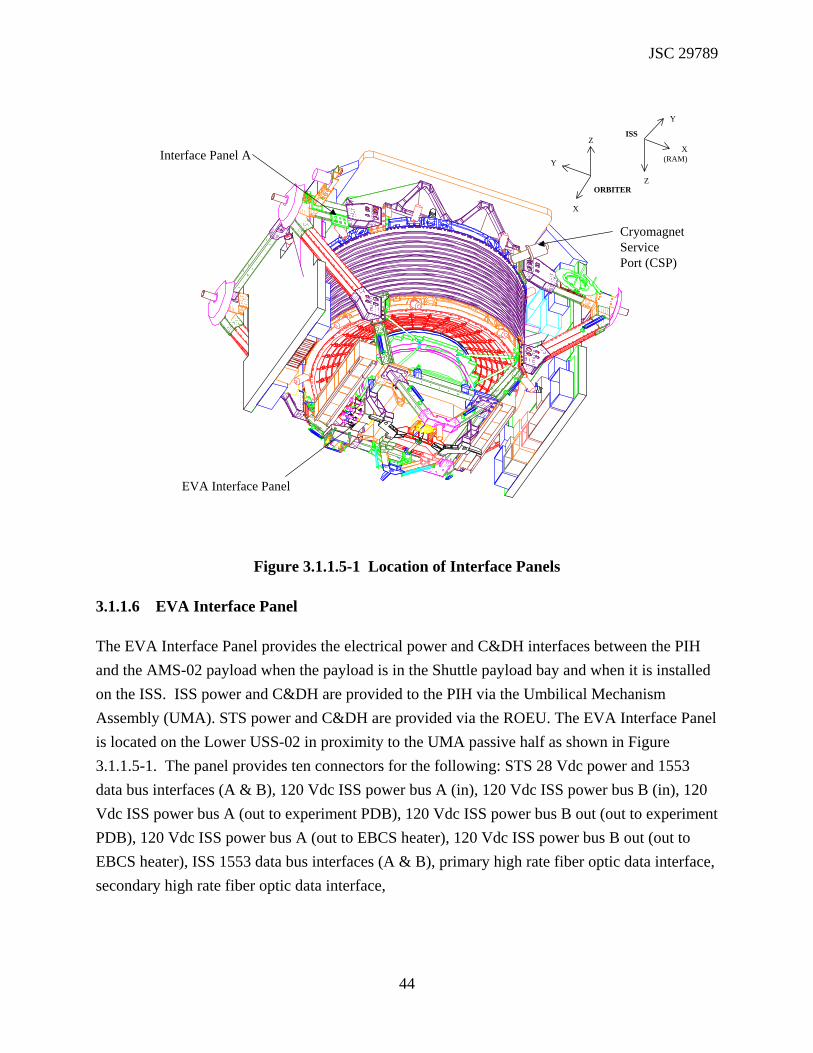
3.1.1.5 Interface Panel A
Interface Panel A provides the electrical power and C&DH interfaces between the PIH and the AMS-02 payload when the payload is in the Shuttle payload bay. Power and C&DH are provided to the PIH via the Payload Disconnect Assembly (PDA) (orbiter side) through the Remotely Operated Electrical Umbilical (ROEU) (PIH side). Interface Panel A is located on the Upper USS-02 adjacent to the ROEU as shown in Figure 3.1.1.5-1. The panel provides six connectors for the following: GSE 120 VDC power from the T-0 umbilical (for ground processing), 28 VDC GSE power for operating the vent pump from the T-0 umbilical (for ground processing), 124 VDC power from the APCU in the Shuttle, 28 VDC ascent power, and two for Command and Data Handling (CD&H): one for Back-up Flight System (BFS) command and one for the RS422 connection.
JSC 29789
44
Interface Panel A
CryomagnetServicePort (CSP)
ISS
ORBITER
X
Y
Z
Z
Y
X(RAM)
EVA Interface Panel
Figure 3.1.1.5-1 Location of Interface Panels
3.1.1.6 EVA Interface Panel
The EVA Interface Panel provides the electrical power and C&DH interfaces between the PIH and the AMS-02 payload when the payload is in the Shuttle payload bay and when it is installed on the ISS. ISS power and C&DH are provided to the PIH via the Umbilical Mechanism Assembly (UMA). STS power and C&DH are provided via the ROEU. The EVA Interface Panel is located on the Lower USS-02 in proximity to the UMA passive half as shown in Figure 3.1.1.5-1. The panel provides ten connectors for the following: STS 28 Vdc power and 1553 data bus interfaces (A & B), 120 Vdc ISS power bus A (in), 120 Vdc ISS power bus B (in), 120 Vdc ISS power bus A (out to experiment PDB), 120 Vdc ISS power bus B out (out to experiment PDB), 120 Vdc ISS power bus A (out to EBCS heater), 120 Vdc ISS power bus B out (out to EBCS heater), ISS 1553 data bus interfaces (A & B), primary high rate fiber optic data interface, secondary high rate fiber optic data interface,

JSC 29789
45
3.1.1.7 Interface Panel Cables to J-Crates and Power Distribution Box (PDB)
Interface cables will be provided to connect the power and C&DH feeds at the interface panels to the AMS-02 experiment. The data and interface electronics for the experiment will be housed in electronics crates on the outside of the USS-02 (see figures 3.1-2 and 3.1-4). The data and interface electronics will enable the connection of the experiment components to the ISS and STS data systems. The PDB is mounted on the USS-02 near the passive UMA. The purpose of the PDB is to provide the power interface circuitry between the AMS-02 and the ISS and STS. The electronics crates and PDB are not a part of the PIH. 3.1.1.8 Digital Data Recording System (DDRS-02)
During the Shuttle portion of the mission, the AMS-02 will utilize an SSP-provided Portable Computer System (PCS) level PC with expansion chassis, replaceable hard-drives, internal Small Computer Systems Interface-II (SCSI-II), and a payload supplied DIGI-board interface card to record AMS-02 High Rate data. The DDRS-02 will record data continuously during the AMS-02 operation on the Shuttle.
3.1.1.9 Interface Brackets for SSP and ISSP Supplied Hardware
Interface brackets are required to structurally attach the SSP and ISSP supplied hardware to the USS-02. Brackets are required for the SSP-provided FRGF and ROEU, and the ISSP-provided PVGF, UMA and EBCS.
3.1.1.10 Thermal Blankets
Thermal blankets will be used in conjunction with the thermal control system (TCS) to protect AMS-02 components from temperature extremes. Standard NASA Multi-layer Insulation (MLI) will be used for fabrication of the thermal blankets. MLI will also be used in the cryogenic insulation system inside the Vacuum Case.
3.1.2 AMS-02 Interface Description
The Unique Support Structure-02 (USS-02) is used to support the AMS-02 Cryomagnet and detectors and to interface the entire AMS-02 Experiment with the Space Shuttle Orbiter and ISS. The USS-02 is comprised of the following five subassemblies: (1) Upper USS-02 Assembly, (2) Vacuum Case Assembly, (3) Lower USS-02 Assembly, (4) Keel Assembly, and (5) passive

JSC 29789
46
Payload Attach System (PAS)/Umbilical Mechanism Assembly (UMA) Assemblies (See Figure 3.1.2-1).
UPPER USS-02 ASSEMBLY (INCLUDES VACUUM CASE)
LOWER USS-02ASSEMBLY
PAS ASSEMBLY
KEEL ASSEMBLY
X
X(RAM)
ISS
Z
Y
Z
ORBITER
Y
Figure 3.1.2-1 USS-02 Exploded View
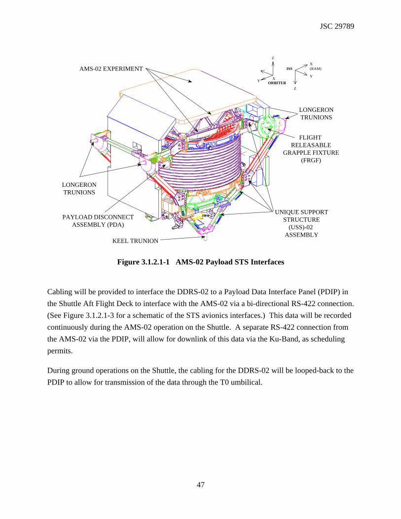
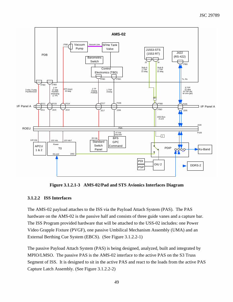
3.1.2.1 STS Interfaces
The USS-02 attaches to the Space Shuttle Orbiter with four longeron trunnions and one keel trunnion. The Space Shuttle Program (SSP) provided hardware that will be attached to the USS-02 includes: one Flight Releasable Grapple Fixture (FRGF) and one Payload Disconnect Assembly (PDA) for the Remotely Operated Electrical Umbilical (ROEU). (See Figure 3.1.2.1-1) Figure 3.1.2.1-2 Shows a cross-section of the AMS-02 Payload in the cargo bay of the Orbiter.
JSC 29789
47
AMS-02 EXPERIMENT
UNIQUE SUPPORTSTRUCTURE
(USS)-02 ASSEMBLY
X
Z
Y ORBITER
X(RAM)
Z
Y
ISS
FLIGHT RELEASABLE
GRAPPLE FIXTURE(FRGF)
LONGERONTRUNIONS
PAYLOAD DISCONNECTASSEMBLY (PDA)
LONGERONTRUNIONS
KEEL TRUNION
Figure 3.1.2.1-1 AMS-02 Payload STS Interfaces
Cabling will be provided to interface the DDRS-02 to a Payload Data Interface Panel (PDIP) in the Shuttle Aft Flight Deck to interface with the AMS-02 via a bi-directional RS-422 connection. (See Figure 3.1.2.1-3 for a schematic of the STS avionics interfaces.) This data will be recorded continuously during the AMS-02 operation on the Shuttle. A separate RS-422 connection from the AMS-02 via the PDIP, will allow for downlink of this data via the Ku-Band, as scheduling permits.
During ground operations on the Shuttle, the cabling for the DDRS-02 will be looped-back to the PDIP to allow for transmission of the data through the T0 umbilical.

JSC 29789
48
(ACC)(ACC)
Figure 3.1.2.1-2 Cross Section of the AMS-02 in the Shuttle Payload Bay
JSC 29789
49
VacuumPump
Vacuum Line SFHe TankValve
BarometricSwitch
ControlElectronics (TBD)
J1553-STS(1553 RT)PDB
AMS-02
J422(RS-422)
I/F Panel A
PDAROEU
PDIPT0APCU1 & 2
StandardSwitchPanel
BFSGPC
Command
1553
Ku-Band
DDRS-2
RS-422
Power
120 Vdc 120 Vdc?120 Vdc28 Vdc
+5 VdcDiscrete
T
OIU 2PDI
PSP
Tx, Rx
3 TP12 awgPwr/Rtn
w/sensing(1 TP)
9 TSP22 awg
(4 TSP perw/ cmn grd)
3 wire, 8 awgPwr/Rtn/Gnd
2 TP22awgPri/Red
1 TSP22awg
9TP (max)20 awg
Stub B1 TSP22 awg
1553 BusA & B
I/F Panel A
Stub A1 TSP22 awg
J3 J4
J100
P100
J205
P205P206
J206
PTBD
JTBD
P217
J217
P214
J214
P215
J215J211
P211
BC
JTBD JTBD
JTBD
JTBD JTBD
JTBD
Figure 3.1.2.1-3 AMS-02/Pad and STS Avionics Interfaces Diagram
3.1.2.2 ISS Interfaces
The AMS-02 payload attaches to the ISS via the Payload Attach System (PAS). The PAS hardware on the AMS-02 is the passive half and consists of three guide vanes and a capture bar. The ISS Program provided hardware that will be attached to the USS-02 includes: one Power Video Grapple Fixture (PVGF), one passive Umbilical Mechanism Assembly (UMA) and an External Berthing Cue System (EBCS). (See Figure 3.1.2.2-1)
The passive Payload Attach System (PAS) is being designed, analyzed, built and integrated by MPIO/LMSO. The passive PAS is the AMS-02 interface to the active PAS on the S3 Truss Segment of ISS. It is designed to sit in the active PAS and react to the loads from the active PAS Capture Latch Assembly. (See Figure 3.1.2.2-2)

JSC 29789
50
The data and interface electronics for the AMS-02 experiment will be housed in electronics crates on the outside of the Unique Support Structure-02 (USS-02). The data and interface electronics will enable the connection of the AMS-02 experiment to the ISS and STS data systems.
ISS
ORBITER
X
Y
Z
ZY
X(RAM)
PAYLOAD ATTACHSYSTEM (PAS)PASSIVE HALF
UMBILICALMECHANISM
ASSEMBLY (UMA)
POWER VIDEOGRAPPLE FIXTURE
(PVGF)
EXTERNAL BERTHING CUE SYSTEM
(EBCS)
Figure 3.1.2.2-1 AMS-02 Payload ISS Interfaces

JSC 29789
51
Figure 3.1.2.2-2 AMS-02 Payload Attached to the Active PAS on the S3 – Z Inboard PAS Site The AMS-02 will be equipped with an ISS provided passive Umbilical Mechanism Assembly (UMA) that will be mated to the ISS active UMA when the AMS is installed on the ISS. MPIO/LMSO provided cables will run from the back side of an Extravehicular Activity (EVA) accessible interface panel to the appropriate interface boxes on the AMS and the Electronic Berthing Cues System (EBCS) for both power and data cables (See Figure 3.1.2.2-3). Also, MPIO/LMSO will add the appropriate EVA connectors to the cable bundle supplied with the passive UMA for attachment to the front of the EVA Interface Panel (See Figure 3.1.2.2-3). This will be to provide the interfacing between the AMS-02 data/interface electronics and the ISS data systems, and the AMS-02 experiment power distribution system and the ISS electrical power system via the UMA.
AMS-02 PAYLOAD
S3 TRUSS
PAS SITES
UPPER INBOARD
UPPER OUTBOARD

JSC 29789
52
J1553-Z(1553 RT)PDB
AMS-02
JFOM-A
4 TSP*16 awg
UMA
120 Vdc
Tx, Rx
3 wire, 8 awgPwr/Rtn/Gnd
J1553-Y(1553 RT)
ISS 1553
BC
3 wire, 8 awgPwr/Rtn/Gnd
APS
HRDLFiber-Optic
Pair
HRDL
JFOM-B
EVAReplaceable
ACOP
Bus BRPCM-IIBus A
RPCM-II
HRDLFiber-Optic
Pair
* These Twisted Shielded Pairs are designed to be looped back on the EVA connector whichattaches to the UMA cable, to supply power to the Fiber Optic modules (from AMS) only whenrequired.
AMS CollaborationProvided Hardware
Integration Hardware
Ku-Band
3 wire, 12 awgPwr/Rtn/Gnd
**
Bus Stub A,B/Address/Parity
8 TSP22awg
3 wire, 8 awgPwr/Rtn/Gnd
3 wire, 8 awgPwr/Rtn/Gnd
JLIF
6 TSP22awg
Address/Parity
1 TSPStub B
1 TSP22 awgStub A
6 TSP22awg
Address/Parity
2 TSPStub A,B
1 TSP22 awg
4 TSP*16 awg
PX1 PX2P13 P14Y_J1 Y_J2 Y_J3 Z_J1 Z_J2 Z_J3
J1
P19
J101B
P101
J101AJ104J103
P103P112P111J112J111
J122 J121
Figure 3.1.2.2-3 AMS-02/ISS Avionics Interconnect Diagram
Some AMS-02 electrical cables will be required in the pressurized module to provide data interfacing between the ACOP and the AMS-02 instrument located on the S3 Truss. The ACOP will house the hard drive recorder and other data interfaces for the AMS-02. Electrical cables will also be required to provide power to the ACOP from the EXpedite the PRocessing of Experiments to Space Station (EXPRESS) Rack. The ACOP is not a part of the PIH.
The AMS-02 Power Distribution Box (PDB) is mounted on the USS-02. The purpose of the PDB is to provide the power interface circuitry between the AMS-02 and the ISS and STS. The PDB receives 124v dc power from either or both of the ISS power buses or the STS. It converts this voltage to 28v dc for distribution to the various AMS-02 subsystems, assuring compliance to the power requirements of SSP 57003 and ICD-2-19001 (See Figure 5.11.1). The PDB also distributes the 124v dc power to the AMS-02 Magnet Cryo Avionics Box (CAB) and to the Cryocooler Controllers.

JSC 29789
53
3.2 CHARACTERISTICS
3.2.1 Functional Performance
The PIH performs the following functions:
• The PIH serves as the structure for mounting the detectors and components of the AMS Experiment including the Cryomagnet.
• The PIH provides the mechanical and electrical interfaces between the AMS Experiment and the Orbiter for launch, transfer to orbit, return from orbit, and landing.
• The PIH provides the mechanical and electrical interfaces between the AMS Experiment and the ISS for the duration of the on-orbit life of the experiment.
• The PIH provides interfaces to the SRMS and the SSRMS via the Program-provided FRGF and PVGF.
3.2.1.1 Experiment Interfaces Functional Performance
The PIH shall provide interfaces with the experiment hardware per JSC 29095, Part II, Alpha Magnetic Spectrometer - 02 (AMS-02) Experiment/Payload Integration Hardware (PIH) Interfaces.
3.2.1.2 STS Interfaces Functional Performance
The PIH shall provide interfaces with the Shuttle Orbiter per NSTS/AMS ICD-A-TBD, Shuttle Orbiter/AMS-02 Cargo Element Interfaces.
3.2.1.3 ISS Interfaces Functional Performance
The PIH shall provide interfaces with the ISS per SSP 57213, Alpha Magnetic Spectrometer (AMS–02) Attached Payload Hardware Interface Control Document.
3.2.1.4 RMS Interfaces Functional Performance
The PIH shall provide interfaces with the SRMS and SSRMS via the FRGF and PVGF per SSP 57213, Alpha Magnetic Spectrometer (AMS–02) Attached Payload Hardware Interface Control Document.

JSC 29789
54
3.2.2 Physical
3.2.2.1 Weight/Center of Gravity (CG)
Total AMS-02 Payload weight shall not exceed 14,809 lbs (6718 kg). The current estimated weight of the PIH is 3,238 lbs. (1469 kg) for the STS hardware and 590 lbs. (268 kg) for the ISS hardware. The STS hardware includes the Unique Support Structure–02 and the Cryomagnet Vacuum Case. The ISS hardware includes the PAS, UMA, PVGF, and EBCS. The AMS-02 experiment weight in its entirety shall not exceed 10,981 lbs. (4981 kg).
The current estimated CG for the AMS-02 Payload (configuration as of November 2002) in the AMS-02 coordinate system is: CGX = –0.2 in., CGY = 2.6 in., CGZ = –6.9 in. Table 3.2.2.1-1 depicts the AMS-02 Payload CG with respect to the PAS, S3, and S0 coordinate systems. Table 3.2.2.1-2 shows the location of the AMS-02 Origin with respect to the PAS, S3, and S0 coordinate systems.
TABLE 3.2.2.1-1 – ESTIMATED CG OF THE AMS-02 PAYLOAD IN THE PAS, S3, AND S0 COORDINATE SYSTEMS
CGX CGY CGZ
PAS2 –2.6 11.6 65.2
S3 –36.3 141.7 –146.2
S0 –36.3 842.7 –146.2
TABLE 3.2.2.1-2 – LOCATION OF THE AMS-02 ORIGIN WITH RESPECT TO THE PAS, S3, AND S0 COORDINATE SYSTEMS
CGX CGY CGZ
PAS2 0.0 13.3 71.9
S3 –33.7 140.0 –152.8
S0 –33.7 841.0 –152.8
3.2.2.2 Dimensions/Volume
The stowed and deployed dimensions of the AMS Payload are provided in table 3.2.2.2-1. Height of the payload is measured from the tip of the keel trunnion to the furthermost surface of the TCS Radiator on the top of the TRD. Width of the payload is measured from the tips of the

JSC 29789
55
port and starboard trunnions. Length is measured from the tip of the tip of the PVGF to the forward edge of the ROEU PDA.
TABLE 3.2.2.2 – DIMENSIONS OF THE AMS-02 PAYLOAD
In Orbiter Cargo Bay Attached to ISS
Height 152.24 in (386.8 cm) 159.66 in (405.5 cm)
Width 193.00 in (490.2 cm) 193.00 in (490.2 cm)
Length 126.55 in (321.4cm) 127.43 in (323.7 cm)
3.2.2.3 Power Consumption
The AMS-02 Payload requires 2100 watts of power from the orbiter during the Shuttle phases of the mission. During berthing operations, the payload requires 1500 watts from the Space Station Remote Manipulator System (SSRMS) via the PVGF. Mounted to the S3 Truss, the AMS requires 2100 watts from the ISS.
3.2.3 Environmental
3.2.3.1 Thermal
The AMS-02 PIH shall be designed to meet the Thermal Environment requirements of SSP 57003, paragraph 3.5.1.2.
3.2.3.2 Pressure
The AMS-02 Payload will be exposed to an on-orbit minimum pressure environment of 1.93E-09 pounds per squire inch absolute (psia) (1.0 x 10E-07 Torr). This is to be used for design and analysis purposes. This requirement is found in SSP 57003, paragraph 3.5.1.1
3.2.3.3 Vibration
Table 3.2.3.3-1 provides Flight Random Vibration Levels (FRVL) environment data for the AMS-02 experiment (ref: JSC 28792, Rev. B). This level applies to the payload trunnions. Table 3.2.3.3-2 provides Minimum Workmanship Levels (MWL) environment data for AMS-02 experiment (ref: JSC 28792, Rev. B)

JSC 29789
56

JSC 29789
57
TABLE 3.2.3.3-1 FLIGHT RANDOM VIBRATION ENVIRONMENT
FREQUENCY (Hz) LEVEL
X-Axis 20 - 58
58 - 125
125 - 300
300 - 900
900 - 2000
.0025 g2 / Hz
+9 Db / Octave
0.025 g2 / Hz
-9 dB / Octave
.001 g2 / Hz
(Overall = 3.1 g RMS)
Y-Axis 20 - 90
90 - 100
100 - 300
300 - 650
650 - 2000
.008 g2 / Hz
+9 dB / Octave
0.01 g2 / Hz
-9 dB / Octave
.001 g2 / Hz
(Overall = 2.3 g RMS)
Z-Axis 20 - 45
45 - 125
125 - 300
300 - 900
900 - 2000
.009 g2 / Hz
+3 dB / Octave
0.025 g2 / Hz
-9 dB / Octave
.001 g2 / Hz
(Overall = 3.2 g RMS)

JSC 29789
58
TABLE 3.2.3.3-2 MINIMUM WORKMANSHIP LEVELS
All Axes 20 Hz
20-80 Hz
80-500 Hz
500-2000 Hz
2000 Hz
Overall = 6.8 Grms
0.1g2 / Hz
+3 dB / Octave
0.04 g2 / Hz
-3 dB / Octave
0.01g2 / Hz
(MWL Test Duration: 60 seconds per axis)
3.2.3.4 Acceleration
A. Primary Structure
1. The AMS-02 and its subsystems shall be designed to withstand an on-orbit acceleration environment including reboost having peak transient accelerations as defined in Table 3.2.3.4-1.
B. Secondary Structure
1. The AMS-02 and its subsystems shall be designed to withstand an on-orbit acceleration environment including reboost having peak transient accelerations of up to 0.185 g’s, a vector quantity acting in any direction.
2. The AMS-02 and its subsystems shall be designed to withstand berthing the AMS-02 in its berthing configuration having peak transient accelerations of up to 0.185 g’s, a vector quantity acting in any direction. This criteria is to be used as a component load factor applied to the subsystem’s center of gravity.
This requirement is found in the ISS IRD # SSP 57003, Section 3.5.1.12.
Table 3.2.3.4-1 PEAK TRANSIENT ACCELERATIONS

JSC 29789
59
NX (m g) NY (m g) NZ (m g)
Case 1 +39.7 +13.2 +13.2
Case 2 +7.7 +55.6 +11.1
Case 3 +36.5 +12.8 +24.6
3.2.3.5 Shock
N/A.
3.2.3.6 EMI/EMC
3.2.3.6.1 EMI
Attached Payloads shall meet all Electromagnetic Interference (EMI) requirements of SSP 30237.
Alternately, Attached Payloads may choose to accept a minimal increase of EMI risk with a somewhat less stringent Electrical Field Radiated Susceptibility (RS03) requirement on equipment considered to be non–safety critical to the vehicle and crew. The tailored RS03 requirement, shown below, will hereafter be denoted RS03PL.
FREQUENCY RS03PL LIMIT (V/m) 14 KHz – 400 MHz 5 400 MHz – 450 MHz 30 450 MHz – 1 GHz 5 1 GHz – 5 GHz 25 5 GHz – 6 GHz 60 6 GHz – 10 GHz 20 13.7 GHz – 15.2 GHz 25
3.2.3.6.2 EMC
AMS-02 EMC design will be exposed to the environment as specified in SSP 30243, paragraph 3.2.3, including applicable references. This will be used for design and analysis purposes.

JSC 29789
60
This requirement is found in the ISS IRD SSP 57003, Section 3.5.1.6.
3.2.3.7 Humidity
The AMS-02 PIH will be exposed to an external environment of 0% relative humidity during on–orbit operations. This is to be used for design and analysis purposes.
3.2.3.8 Acoustic Environment
The AMS-02 PIH will be exposed to an acoustic environment as specified in NSTS-21000-IDD-ISS, paragraph 4.1.1.5. This is to be used for design and analysis purposes.
3.2.3.9 Meteoroids and Orbital Debris
The Attached Payload will be exposed to the M/OD environments as specified in SSP 30425, paragraph 8.0. Parameters of ISS M/OD environments definition are given in Table 3.2.3.9–1 and NASA TM 104825. This is to be used for design and analysis purposes.
TABLE 3.5.1.11–1 PARAMETERS FOR METEOROIDS AND ORBITAL DEBRIS ENVIRONMENTS DEFINITION
Altitude 215 nautical miles (400 km)
Orbital inclination 51.6 degrees
Space Station attitude LVLH 10% of the time (Orbiter attached)
TEA 90% of the time (Orbiter not attached)
Solar flux 70 x 104 Jansky (F10.7 – 70)
Orbital debris density1 2.8 gm/cm3
Maximum debris diameter2 20 cm
Note: 1 For M/OD critical items (see 6.1) only. 2 High degree of confidence of collision avoidance for this size and larger orbital debris objects.
3.2.3.10 Atomic Oxygen
A. The Attached Payload will be exposed to a flux of 5.0 x 10E21 atoms per cm2 per year for the on-orbit exposure duration. This is to be used for design and analysis purposes.

JSC 29789
61
Note: The Atomic Oxygen (AO) environment is not applicable to Attached Payload internal surfaces and equipment, except where exposed to the external AO environment during ISS operations.
B. Surfaces exposed 30 days or less will be exposed up to 4.4 x 10E19 atoms per cm2 per day. This is to be used for design and analysis purposes.
Silver plated hardware shall not be used per SSP 57003, paragraph 3.6.4.
3.2.3.11 External Contamination
The AMS-02 PIH will be exposed to on–orbit external contamination environments as defined in SSP 30426, External Contamination Control Requirements, paragraphs 3.4 and 3.5.
3.2.3.12 Ionizing Radiation
3.2.3.12.1 Ionizing Radiation Dose
Attached Payloads shall be designed to not produce an unsafe condition or one that could cause damage to external equipment as a result of exposure to a total dose specified in SSP 30512, Ionizing Radiation Design Environment, paragraph 3.1.2.
3.2.3.12.2 Nominal Single Event Effects Ionizing Radiation
Attached Payloads shall be designed to operate in and to not produce an unsafe condition or one that could cause damage to other equipment as a result of exposure to the radiation dose environment specified in SSP 30512, paragraph 3.2.1.
3.2.3.12.3 Extreme Single Event Effects
Attached Payloads shall be designed to not produce an unsafe condition or one that could cause damage to external equipment as a result of exposure to extreme Single Event Effect (SEE) ionizing radiation assuming exposure levels specified in SSP 30512, paragraph 3.2.2.
3.2.4 Reliability
3.2.4.1 Failure Tolerance
Although many of the AMS-02 Payload subsystems will be designed to be single fault tolerant for mission success, major systems including the Cryomag, SFHe Tank, Vacuum Case, TRD Gas

JSC 29789
62
Supply System, and each of the detectors are zero fault tolerant. Loss of the TRD Gas Supply System or any one of the detectors would limit only the scientific value of the experiment. Loss of the magnet or rupture of the SFHe Tank would effectively end the science for which the AMS Experiment was designed. The SFHe Tank is contained in the Vacuum Case but is not considered part of the PIH.
3.2.4.2 Failure Propagation
A single failure of the AMS-02 PIH end item in a functional path shall not induce any other failures external to the failed end item.
3.2.4.3 Failure Detection, Isolation, and Recovery (FDIR)
The AMS-02 PIH is a passive support structure and has no FDIR requirements.
3.2.5 Maintainability
The AMS-02 PIH is a passive support structure designed such that no on-orbit maintenance is required for the life of the mission.
3.2.6 Transportability
3.2.6.1 Ground Transportability
The AMS-02 Payload and associated ground handling equipment (GHE) is being designed primarily for air transport. The Primary Support Stand (PSS) and Lower USS-02 Support Fixture are being designed specifically to be compatible with Boeing 747 cargo aircraft.
3.2.6.2 Transport to Orbit
The AMS-02 payload shall be capable of being transported to orbit by the Orbiter in accordance with NSTS 21000-IDD-ISS. The AMS-02 payload will be transported in the Orbiter cargo bay. Design loads are defined in JSC 28792, AMS-02 Structural Verification Plan for the STS and the ISS. The ACOP will be transported in the Orbiter mid-deck or in an MPLM.
3.3 DESIGN AND CONSTRUCTION
3.3.1 Materials, processes and parts

JSC 29789
63
3.3.1.1 Materials and Processes
a. Materials and processes for flight hardware shall meet the requirements of SSP 30233, “Space Station Requirements for Materials and Processes,” as implemented by JSC 27301, “Material Control Plan for JSC Space Station GFE”.
b. Materials and process for payloads shall meet the requirements of SE-M-0096, “General Specification for Materials and Processes for JSC Controlled Payloads”.
c. Material Certification will be documented with a Materials Memorandum for inclusion in the Certification Data Package (Ref: SMD-TQM Form 3 per JSC 27622, Section 12.5.2). Materials Usage Agreements will be provided only as needed.
d. The project will utilize the standard JSC inspection and bonded stores practices for parts handling and control.
e. All Commercial-Off-The-Shelf (COTS) hardware that cannot provide material certifications, traceable parts, or workmanship processes will be evaluated for further testing that will be used to supplement the acceptance testing for that hardware.
f. Materials and processes shall meet SE-M-0096, “General Specification for Materials and Processes Requirements for JSC Controlled Payloads,” and the materials requirements of NSTS 1700.7B, section 209 and NSTS 1700.7B ISS Addendum 209.
g. Nonmetallic materials shall be selected to the maximum extent possible from JSC-09604, “JSC GFE Materials Selection List and Materials Documentation Procedures.”
h. If fungus nutrient materials are utilized, adequate tests or analyses shall be conducted to insure compatibility.
i. Selection of materials shall be approved by the Structural Mechanical Design and Analysis Branch (ES5) of the JSC Structures and Mechanics Division.
3.3.1.2 Electrical, Electronic and Electromechanical (EEE) Parts
EEE parts for all Payload Integration Flight Hardware shall be selected in accordance with JSC 61360, “Engineering Directorate Certified Parts Approval Process (EDCPAP) and SSP 30312, Electrical, Electronic, and Electromechanical (EEE) and Mechanical Parts Management and Implementation Plan for Space Station Program.
LMSO will provide an as-built parts list and perform component stress analysis for all Payload Integration Hardware. EEE parts traceability to the serial and lot number will be provided for

JSC 29789
64
Payload Integration Hardware. Parts will be derated in accordance with SSP 30312, Electrical, Electronic, and Electromechanical (EEE) and Mechanical Parts Management and Implementation Plan for Space Station Program, Appendix B.
3.3.2 Structural Design
The AMS-02 Payload shall be designed to meet the structural design requirements of SSP 57003, paragraphs 3.1.1.7 and 3.1.1.8
3.3.3 Nameplates and Product Marking
a. Except for commercial off-the-shelf hardware, nameplates shall conform to the requirements of JSC-SPEC-M1B.
b. Except for commercial off-the-shelf hardware, other labels, decals, placards and product marking shall conform to the requirements of SSP 57003, paragraph 3.10.
c. A manufacturer’s label containing part number and serial number shall be provided in accordance with MIL-STD-130, paragraph 4.0.
3.3.4 Workmanship
Except for commercial off-the-shelf hardware, workmanship standards shall comply with:
a. NASA-STD-8739.3, “Requirements for Soldered Electrical Connections”
b. NASA-STD-8739.4, “Requirements for Interconnecting Cables, Harnesses and Wiring”
c. MIL-STD-1130B, “Connections, Electrical, Solderless Wrapped”
d. IPC-6011, “U.S.A. Standard for the Manufacture of Printed Circuit Boards, Quality and Reliability Assurance Requirements”
e. IPC-6012, “U.S.A. Standard for the Manufacture of Printed Circuit Boards; Finishes, Plating, Traces, Holes/Vias, Electrical, Mechanical and Environmental Requirements”
a. NASA-STD-8739.1, "Workmanship Standard for Staking and Conformal Coating of Printed Wiring Boards and Electronic Assemblies"
b. IPC-2221 "Generic Standard on Printed Board Design" and IPC-2222- "Sectional Design Standard for Rigid Organic Printed Boards"

JSC 29789
65
c. ANSI/ESD S20.20-1999, Development of an Electrostatic Discharge Control Program for Protection of Electrical and Electronic Parts, Assemblies and Equipment (Excluding Electrically Initiated Explosive Devices)
d. NASA-STD-8739.2, "Workmanship Standard for Surface Mount Technology"
e. NASA-STD-8739.5, “Workmanship Standard for Fiber Optic Terminations, Cable Assemblies, and Installation”
The external surfaces of the AMS-02 Payload shall conform to Visibly Clean–Standard (VC–S) as specified in SN–C–0005, NSTS Contamination Control Requirements Manual.
3.3.5 Human Engineering
The AMS-02 Payload shall be designed to meet the requirements of SSP 57003, section 3.8.3, Human Engineering Design.
3.3.6 Safety
The AMS-02 Payload shall be designed to meet the requirements of SSP 57003, sections 3.2.2.5, Safety Requirements and 3.8.4, Human Engineering Safety. Safety issues and abatements are documented in JSC 29075, Phase 0/I Flight Safety Data Package for the Alpha Magnetic Spectrometer-02 (AMS-02) and JSC 29076, Phase 0/I Ground Safety Data Package for the Alpha Magnetic Spectrometer-02 (AMS-02). Additional documentation will be provided to support the Phase II/III Safety Reviews
"The AMS-02 Payload shall be designed to meet the requirements of NSTS 1700.7 (current issue), "Safety Policy and Requirements For Payloads Using the Space Transportation System" and the NSTS 1700.7 ISS Addendum (current issue), "Safety Policy and Requirements For Payloads Using the International Space Station".
3.3.7 Lifetime
The AMS-02 Payload shall be designed to meet the requirements of SSP 57003, paragraphs 3.1.1.3 and 3.1.1.4. The AMS will be designed to operate on-orbit for a minimum period of three years.
3.3.8 Security
The AMS-02 Payload has no unique security requirements.
3.4 LOGISTICS

JSC 29789
66
3.4.1 Maintenance
3.4.1.1 On-Orbit Maintenance
The AMS-02 Payload has no planned on-orbit maintenance activities. Accommodations for contingency EVAs (i.e. for the mating of connectors) will be considered in the design of the hardware.
3.4.1.2 Ground Maintenance
There is no planned nominal ground maintenance required for any Payload Integration Supplied Hardware. In the event that a contingency arises that requires a repair to Payload Integration Flight Hardware, the situation will be assessed and a repair plan developed.
3.4.2 Supply
The Payload Integration Hardware is not foreseen to require a supply source for critical parts. If complications develop during fabrication this issue may be re-addressed; however, the purchase of spares is foreseen as a more viable solution based on the hardware.
3.4.3 Spares
The Payload Integration Flight Hardware is not foreseen to require flight spares; however this may be re-addressed based on complications that may arise during fabrication/testing.

JSC 29789
67
4. PREPARATION FOR DELIVERY
The requirements specified herein will govern the preparation for shipment and the transportation of the AMS-02 to all contractor and Government facilities or test sites. The methods of packaging, as well as the necessary special controls during transportation, will adequately protect the AMS-02 from damage or degradation in reliability or performance that could be incurred from natural and induced environments encountered during transportation and subsequent storage.
Packaging, handling, and transporting will be in general accordance with the guidelines of NHB-6000.1 (1D), “Requirements for Packaging, Handling and Transportation for Aeronautical and Space System Equipment and Associated Components,” as supplemented or amended by the following paragraphs.
4.1 PACKAGING LEVELS AND METHODS
Packaging and packing shall be in general accordance with MIL-STD-2073-1C, “Standard Practice for Military Packaging.”
4.2 PACKAGING DESIGN VERIFICATION/QUALIFICATION
Tests to verify that packages meet performance requirements (including vibration, drop (shock), superimposed load, tip over, and impact) will not be performed because verification can be accomplished by analysis, assessment, or similarity.
4.3 MILITARY TRANSPORTATION PROCEDURES DOCUMENTATION AND REPORTS
Shipments entered into the military airlift system shall be documented and reported in accordance with DODR-4500.32R, “Military Standard Transportation and Movement Procedures.”
4.4 MARKING FOR SHIPMENT
Interior and exterior containers will be marked and labeled in accordance with MIL-STD-129, “Marking for Shipment and Storage,” except that labels with lettering of an appropriate size may be used in lieu of stenciling for all markings.

JSC 29789
68
5. VERIFICATION
The Quality Management System (QMS) for this project shall be in accordance JPD 5335.1 for onsite design, development, and manufacturing. For offsite activities the QMS shall be SAE, AS9100 - Model for Quality Assurance in Design/Development, Production, Installation, and Servicing”, as tailored for that particular procurement. Where existing JSC contracts are used for design, development, or manufacturing the contract required QMS shall prevail.

JSC 29789
A-1
APPENDIX A ACRONYMS AND ABBREVIATIONS A Amps AC Alternating Current ACASS Active Common Attach System Simulator ACC Anti-coincidence Counter ACC Anti-Coincidence Counter ACOP AMS Crew Operations Post AHV Air-Heated Vaporizer AMS Alpha Magnetic Spectrometer ASSY Assembly C Celsius CAB Cryomagnet Avionics Box CAS Common Attach System CCP Configuration Control Panel CDR Critical Design Review CDC Cool Down Circuit CDU Cool Down Unit CFC Carbon Fiber Composite CG Center of Gravity CIR Cargo Integration Review cm centimeter CO2 Carbon Dioxide COTS Commercial Off The Shelf CPU Central Processing Unit CR/DIR Change Request/Directive CSR Customer Support Room CSP Cryo-Magnet Self Protection Cu Copper DC Direct Current DDRS-02 Digital Data Recording System-02 DLT Digital Linear Tape DOE Department Of Energy

JSC 29789
A-2
APPENDIX A ACRONYMS AND ABBREVIATIONS (Continued) E Energy e+ positron e- electron EBCS External Berthing Cue System ECAL Electromagnetic Calorimeter EGSE Electrical Ground Support Equipment EMC Electromagnetic Compatibility EMI Electromagnetic Interference ETH Eidgenossische Technische Hochschule EVA Extravehicular Activity EXPRESS EXpedite the PRocessing of Experiments to Space Station F Fahrenheit F Filter F/E Front-End Fe55 Iron 55 FOR Flight Operations Review FPSR Flight Planning And Stowage Review FRGF Flight Releasable Grapple Fixture FRR Flight Readiness Review g gram (also gravity) G Gravity (also g) Gbytes Giga Bytes GeV Giga Electron Volts GFE Government Furnished Equipment GHe Gaseous Helium GHE Ground Handling Equipment GPS Global Positioning System GSE Ground Support Equipment GSFC Goddard Space Flight Center He Helium HR Hazard Report

JSC 29789
A-3
APPENDIX A ACRONYMS AND ABBREVIATIONS (Continued) HRDL High Rate Data Link HRS Helium Recovery System HV High Voltage HVM Helium and Vacuum Manifold Hz Hertz ICD Interface Control Document IDD Interface Design Document IDRD Increment Definition And Requirements Document in inch IPT Integrated Product Team ISF Intermediate Support Fixture ISS International Space Station ISSP International Space Station Program JSC Lyndon B. Johnson Space Center K Kelvin kg kilogram KHB KSC Handbook KSC John F. Kennedy Space Center KW Kilowatt L Liter (also l) lbs pounds LCD Liquid Crystal Display LHSS Liquid Helium Supply System LM Lockheed Martin LMSO Lockheed Martin Space Operations LTO Linear Tape Open µC microcurie m meter

JSC 29789
A-4
APPENDIX A ACRONYMS AND ABBREVIATIONS (Continued) MCA Multi-Channel Analyzer MCC Mission Control Center OR Monitoring and Control Computers MDL Master Document List MHT Main Helium Tank MIL Military MIP Mission Integration Plan MIT Massachusetts Institute Of Technology MLI Multilayer Insulation M/OD Meteoroid and Orbital Debris MPCA Mid Power Control Assembly MPLF Multi-Purpose Lifting Fixture MPLM Mini-Pressurized Logistics Module MPPF Multi-Payload Processing Facility MRDL Medium Rate Data Link MSDS Material Safety Data Sheet N/A Not Applicable NASA National Aeronautics And Space Administration NBL Neutral Buoyancy Laboratory NH3 Ammonia NHB National Aeronautics And Space Administration Handbook NSTS National Space Transportation System P Pressure Sensor p+ proton p- anti-proton PAS Payload Attach System PC Personal Computer PCASS Payload Common Attach System Simulator PCR Payload Changeout Room PCS Portable Computer System PDA Payload Disconnect Assembly PDB Power Distribution Box PDI Payload Data Interleaver

JSC 29789
A-5
APPENDIX A ACRONYMS AND ABBREVIATIONS (Continued) PDIP Payload Data Interface Panel PDR Preliminary Design Review PEEK Polyether Ether Ketone PFR Portable Foot Restraint PIH Payload Integration Hardware PLF Primary Lifting Fixture PM Photo Multiplier PMT Photo Multiplier Tube POCC Payload Operations Control Center PSS Primary Support Stand PVGF Power Video Grapple Fixture RAID Redundant Arrays of Inexpensive Disks RGA Residual Gas Analyzer RICH Ring Imaging Cherenkov Counter ROEU Remotely Operated Electrical Umbilical SCSI Small Computer Systems Interface SFHe Superfluid Helium SPEC Specification SRMS Shuttle Remote Manipulator System SSP Space Station Program SSPF Space Station Processing Facility SSRMS Space Station Remote Manipulator System STD Standard STE Special Test Equipment STS Space Transportation System TAS Tracker Alignment System TB Tera-Bytes TBD To Be Determined TBS To Be Supplied TCS Thermal Control System Te Tellurium

JSC 29789
A-6
APPENDIX A ACRONYMS AND ABBREVIATIONS (Continued) TeV Tera Electron Volts TIM Technical Interchange Meeting TOF Time Of Flight TRD Transition Radiation Detector TS Temperature Sensor UIP Utility Interface Panel UL Underwriters Laboratory UMA Umbilical Mechanism Assembly UPS Uninterruptible Power Supply USCM Universal Slow Control Module USS-02 Unique Support Structure-02 V Valve V Volt VAR Verification Acceptance Review VC Vacuum Case VCS Vapor Cooled Shield VCSC Vacuum Case Shipping Container WIF Worksite Interface Xe Xenon