verilog overview prof. macdonald. verilog overview c-like language used to describe hardware vhdl is...
TRANSCRIPT

Verilog Overview
Prof. MacDonald

Verilog Overview
C-Like Language used to describe hardware VHDL is main competitor
– VHDL is more rigorous and typed– VHDL takes longer to write– VHDL is used by 50% of USA
Verilog was originally owned by Cadence Now an open language with standards Used for ASIC design and FPGA programming Verilog HDL : A Guide to Digital Design and
Synthesis by Samir Palnitkar

Simple Example
module counter (reset, clk, count, top); input reset, clk; output [3:0] count; output top;
reg [3:0] count;wire top = count == 4’b1111;
always @(posedge clk) if (reset) count <= 4’b0; else count <= count + 1;endmodule

Simple Example
module counter (reset, clk, count, top); input reset, clk; output [3:0] count; output top;
reg [3:0] count;wire top = count == 4’b1111;
always @(posedge clk) if (reset) count <= 4’b0; else count <= count + 1;endmodule

Simple Example
module counter (reset, clk, count, top); input reset, clk; output [3:0] count; output top;
reg [3:0] count;wire top = count == 4’b1111;
always @(posedge clk) if (reset) count <= 4’b0; else count <= count + 1;endmodule

Simple Example
module counter (reset, clk, count, top); input reset, clk; output [3:0] count; output top;
reg [3:0] count;wire top = count == 4’b1111;
always @(posedge clk) if (reset) count <= 4’b0; else count <= count + 1;endmodule

Simple Example
module counter (reset, clk, count, top); input reset, clk; output [3:0] count; output top;
reg [3:0] count;wire top = count == 4’b1111;
always @(posedge clk) if (reset) count <= 4’b0; else count <= count + 1;endmodule

Simple Example
module counter (reset, clk, count, top); input reset, clk; output [3:0] count; output top;
reg [3:0] count;wire top = count == 4’b1111;
always @(posedge clk) if (reset) count <= 4’b0; else count <= count + 1;endmodule

Simple Example
module counter (reset, clk, count, top); input reset, clk; output [3:0] count; output top;
reg [3:0] count;wire top = (count == 4’b1111);
always @(posedge clk) if (reset) count <= 4’b0; else count <= count + 1;endmodule

Simple Example
module counter (reset, clk, count, top); input reset, clk; output [3:0] count; output top;
reg [3:0] count;wire top = count == 4’b1111;
always @(posedge clk) if (reset) count <= 4’b0; else count <= count + 1;endmodule

Testbench
circuit under test (CUT)counter.v
tb.v testbench
clock gen
reset gen
any other inputs monitors
waveform gen
synthesizable code
unsynthesizable code – artificial and for verification only

Testbench`timescale 1ns/1psmodule tb ();
reg clk, reset; wire [3:0] count;
counter counter1 (.clk(clk), .reset(reset), .count(count), .top( ));
initial clk = 0; //clock generatorinitial forever #10 clk = ~clk; //clock generatorinitial //main stimulus block
begin reset <= 1’b1;
#500 reset <= 1’b0;#1000 $finish;
end
always @(count) $display("counter value is now %x at time %t",count, $time);
initial begin $dumpfile("verilog.dmp"); $dumpvars; endendmodule

Output log (verilog.log)
Compiling source file "tb.v"Compiling source file "counter.v"Highest level modules:tb
counter value is now 0 at time 5counter value is now 1 at time 1005counter value is now 2 at time 1015counter value is now 3 at time 1025counter value is now 4 at time 1035counter value is now 5 at time 356085counter value is now 6 at time 356095counter value is now 7 at time 356105counter value is now 8 at time 356115counter value is now 9 at time 356125counter value is now a at time 356135counter value is now b at time 356145counter value is now c at time 356155counter value is now d at time 356165counter value is now e at time 356175counter value is now f at time 356185counter value is now 0 at time 356195counter value is now 1 at time 356205VERILOG interrupt at time 356210C1 > 0 simulation events (use +profile or +listcounts option to count)CPU time: 0.2 secs to compile + 0.1 secs to link + 6.1 secs in simulationEnd of VERILOG-XL 3.40.p001 Nov 16, 2004 09:58:09

Output Waves

Design Abstraction
High Level Behavioral– C or Matlab
Register Transfer Level (RTL)– describes logic design with C like constructs– modern definition is that RTL is synthesizable
Gate level (netlist)– describes design as a collection of logic gates connected
together – product of synthesizing RTL code
Transistor level (circuit design)– gates (primitives) used in synthesis– details are hidden “under the hood” from logic designers

Simple Design Flow (ASIC/FPGA)
Specification
Architecture
RTL Coding
Simulation
Synthesis
Place, Route, and Timing
standard cell library

Verilog Data Types
Combinatorial logic is represented by wire data type– must be driven by an output or continuous assignment– can be connected to any number of inputs
reg can represent either combinatorial or sequential– regs in verilog are not necessarily flip-flops – are defined by procedural blocks (initial or always)– always blocks with “posedge” are sequential– always blocks without “posedge” are combinatorial– Initial blocks are for verification only (testbenches)
Other less common data types include time, real, integer

Verilog Data Types - busses
Wires and Regs can be defined as vectors
reg [7:0] counter; // 8 bit register of flip-flops
wire [10:2] data_bus; // 9 bit bus
Can be individually addressed
assign output = data_bus[9];
or as a group
assign data_bus_out = data_bus;

Verilog Data Types - Numbers
Specification by <size>’<base><number>
Examples:
wire [7:0] data_bus = 8’hFF; // 8 bit hex number
wire [7:0] data_bus = -1; // unsized – eight ones
wire [7:0] data_bus = 0; // unsized – eight zeros
wire [7:0] data_bus = 8’d10; // 8-bit decimal number
wire [7:0] data_bus = 8’b1010_1010; // 8-bit binary
Underscore can be used for clarity

Arithmetic Operators
- +, -, /, *, % Arithmetic operators imply ALU in synthesis
– Plus operator for addition + – Minus operator for subtraction – – Multiply operator for multiplication *– Division operator / (rarely used except in TBs)– Modulus operator %
Ensure input and output precision is appropriate

Logical Operators
Logical operators take two or more boolean vars and provide a single boolean answer.
If input is a vector, then false if all zeros, otherwise true AND is && OR is ||
wire [3:0] inputA = 4’d3;wire inputB = 1’b0;wire C = inputA && inputB; // C = false or zero

Bitwise Operators
Bitwise operators work on each bit of vector AND & OR | NOT ~ Exclusive OR ^ Exclusive NOR ~^ (compare)
wire [3:0] busA; // 0101wire [3:0] busB; // 0011wire [3:0] busAandB = busA & busB; // 0001

Relational Operators
In synthesis, relational operators imply comparison logic Compare two values and provide a boolean answer
– Equality == – Greater than or Equal >=– Greater than > – Not equal !=– Less than <– Less than or equal to <=
wire [7:0] E = 8’d1111_0111;wire [7:0] F = 8’h0001_0011; assign A = (E == F); // A = 0assign B = (E != F); // B = 1

Unary Operators
Unary operators act on one input variable Not – inverts boolean AND – provides the logical AND of entire bus OR – provides the logical OR of entire bus XOR – provides the exclusive OR of entire bus
wire A;wire B;wire C;wire [7:0] D = 8’b0000_0001; wire [7:0] E = 8’d1111_0111;wire [7:0] F = 8’h0001_0011; assign A = |D; // A checks for 1s in Dassign B = &E; // B checks for 0s in Eassign C = ^F; // C is the parity of F

Shift Operators
Shift <<, >> shifts the index of a bus <vector> >> <number of bits>
Alternative approach is using concatenation wire [3:0] bus = 4’hA;wire [3:0] shifted_bus = bus >> 1; // result is 4’b0101 or 4’h5
wire [3:0] bus = 4’hA;wire [3:0] shifted_bus = {1’b0, bus[3:1]}; // result is 4’b0101

Concatenation Operator
Concatenation Operator {} Used to splice busses together
wire [3:0] A = 4’hA;wire [3:0] B = 4’h5;wire [7:0] C;assign C = {A, B}; // 8’hA5
OR
assign C = {1’b0, A, B[3:1]} // for shift with zero insert

Codition Operator (Mux)
Condition operator used to imply muxes
assign <variable>= <select> ? <option1> : <option0>;
A = B ? C : D; // A = C if B=1 else A = D
This construct is dense and can be confusing if over-used.

Continuous Assignment Statements
Assignment statements assign values to wires and
can be used to describe combinatorial circuits only.
Any change on the right side, effects left side immediately if no delay is specified.
Delay if specified is un-synthesizable and is for tb only.
Ex.
wire C;
assign #2 C = (A & !B) | (!A & B);

Procedural Blocks
Procedural blocks are used to define reg data types and
can be used to describe combinatorial or sequential circuits.
Procedural blocks can use C-like constructs and begin with
always or initial key words.
Each procedural block is an like an independent thread – all running in parallel.
reg Q;
always @(posedge CLK)
if (reset) Q <= 0;
else Q <= D;
QD
CLK

Blocking vs. Non-blocking assignment
Regs is procedural blocks can be defined with blocking or non-blocking assignment.
Use non-blocking for flops and blocking for combinatorial.
always @(posedge CLK)
begin
if (reset) Q <= 0;
else Q <= D;
end
always @(A or B or Sel)
begin
if (Sel) Z = A;
else Z = B;
end
Very common interview question

Blocking vs. Non-blocking assignment
Problem is that a race condition can exist when defining more than one flip-flop with one always block using blocking assignments.
always @(posedge CLK)
begin
B = A;
C = B;
end
D Q
clk1
AD Q
CB0 0->11->00 0->01->0
Other solution is to only define one reg in one always procedural block. Less confusing also.

Verilog Procedural Constructs
If-then-else statement case statement for loop (not used often in synthesizable code)
while loop (not used often in synthesizable code)
System Calls– $display – dumps variable or string to standard output– $time – tells current simulation time– $stop – finishes the simulation– $dumpvar – creates a waveform file for subsequent viewing

State Machine Design Example
s0
s1
0 0
1 0
x z
s2 0 0
1 0 1
1
0 0
X = 0 0 1 1 0 1 1 0 0 1 0 1 0 1 0 0 Z = 0 0 0 0 0 1 0 0 0 0 0 1 0 1 0 0

Alternative Style (moore)
Module detector (clk, reset, in, detect) input clk, reset, in; output detect; reg [1:0] state; wire detect = (state == 3);always @(posedge clk) if (reset) state <=0; else case(state) 2’b00 : if (in) state <= 1; else state <= 0; 2’b01 : if (in) state <= 1; else state <= 2; 2’b10 : if (in) state <= 3; else state <= 0; 2’b11 : if (in) state <= 1; else state <= 2; endcaseendmodule //

Alternative Style (mealy)
Module detector (clk, reset, in, detect) input clk, reset, in; output detect; reg [1:0] state; wire detect = (state == 2) & in;
always @(posedge clk) if (reset) state <=0; else case(state) 2’b00 : if (in) state <= 1; else state <= 0; 2’b01 : if (in) state <= 1; else state <= 2; 2’b10 : if (in) state <= 1; else state <= 0; endcaseendmodule //

Alternative Style (mealy - 2)
Module detector (clk, reset, in, detect) input clk, reset, in; output detect; reg [1:0] state; wire detect = (state == 2) & in;always @(posedge clk) if (reset) state <=0; else case({state,in}) 3’b000 : state <= 0; 3’b001 : state <= 1; 3’b010 : state <= 2; 3’b011 : state <= 1; 3’b100 : state <= 0; 3’b101 : state <= 1; default : state <= 0; // safer// default : state <= 2’bxx; // smaller endcaseendmodule //

Test bench
state_machine
test_bench
clock generator
xclk
sequencegenerator
checkeroptionalzstimulus
circuit under test
Only state_machine is synthesizable. All else is for verificationpurposes only.
resetgenerator

Testbench example - psuedocode
module test_bench ( ); reg x, clk, reset; // reg declarations
initial clk = 0;always forever #100 clk = ~clk; // clk generation
initial begin // sequence generationreset = 1;x = 0;
#(800) reset = 0; @(negedge clk) x = 0; @(negedge clk) x = 1; @(negedge clk) x = 0;
end
state_machine U0 (.in(x), .clk(clk), .detect( ), .reset(reset));endmodule

Testbench Tasks
Task adc_transaction ( ); input [7:0] sample; begin @(posedge convert) serial_data <= 0; @(negedge sclk) serial_data <= sample[7]; @(negedge sclk) serial_data <= sample[6]; @(negedge sclk) serial_data <= sample[5]; @(negedge sclk) serial_data <= sample[4]; @(negedge sclk) serial_data <= sample[3]; @(negedge sclk) serial_data <= sample[2]; @(negedge sclk) serial_data <= sample[1]; @(negedge sclk) serial_data <= sample[0]; $display(“just transferred %x from ADC”,input); endendtask

Testbench monitors for the log file
always @(posedge tb.dut.data_signal) $display(“%d, %x, %x, %t”, tb.dut.count, tb.dut.var1, tb.dut.var2, tb.dut.var3, $time);
These statements provide crucial information about the simwithout having to check the waveforms.

Hierarchy Example (contrived)
module top (clk, reset, in1, out1, out2) // should be name of file - top.v input clk, reset, in1; // all ports as inputs defined output out1, out2; // all ports as outputs defined reg out1; // outputs can redefine as reg reg [1:0] count; // this is an internal reg wire out2; // outputs can redefined as wire wire [1:0] new_count; // this in an internal wire
always @(posedge clk) if(reset) out1 <= 0; else if (new_count == 2’b10) out1 <= in1 && out2; else out1 <= out1;
always @(posedge clk) count <= count + 1;assign out2 = in1 && out1; bottom bottom1 (.inA(count), .outB(new_count)); //instantiation
endmodule

Hierarchy Example (contrived – page 2)
module bottom (inA, outB) // should be name of file bottom.v input [1:0] inA; // all ports as inputs defined output [1:0] outB; // all ports as outputs defined wire [1:0] outB; // outputs can be defined as wire
assign outB = inA + 2’b10; // could be combined with wire above
endmodule

Synthesis effects
wire start;
assign start = ready && request;
Continuous statements always result in combinatorial logic - no flops or latches.

Synthesis effects
Wire [31:0] a ;
Wire [31:0] b ;
Wire the_same ;
Assign the_same = (a == b);
Continuous statements always result in combinatorial logic.
Here is a 32 bit comparator.
Note that the size of the netlist doesn’t necessarily correspond to the number of lines of RTL

Synthesis effects
Always @(D or S or E)
begin
if (S) A = D;
else A = E;
end
Always block without posedge statement is combinatorial.
Always @(*) // verilog 2000
begin
if (S) A = D;
else A = E;
end

Synthesis effects
Wire [31:0] ina;
Wire [31:0] inb;
Reg [31:0] out;
always @(ina or inb or subract)
begin
if (subtract) out = ina + (~inb + 32’h1);
else out = ina + inb;
end
Always block without posedge statement is combinatorial.
This example will result in an ALU function (potentially very large).

Synthesis effects
always @(index)
case (index)
0: decoder_out = 8’h01;
1: decoder_out = 8’h02;
2: decoder_out = 8’h04;
3: decoder_out = 8’h08;
4: decoder_out = 8’h10;
5: decoder_out = 8’h20;
6: decoder_out = 8’h40;
7: decoder_out = 8’h80;
endcase
Always block without posedge statement is combinatorial.
This example will result in decoder (8 3-input AND gates).

Synthesis effects
always @(*)
if (enable) Q = D;
Always block without posedge statement is combinatorial.
This example will has a problem. All cases must be specified.
Here if enable is high, Q=D. What happens if enable is low? Synthesis will add a latch to remember the old value of Q when it is undefined by the if statement. Latches are rarely meant to be used in logic and are a good sign of a problem.
Very common interview question

Synthesis effects
always @(posedge clk)
A <= E;
Always block with posedge clk statement is sequential.
This example will result in a simple non-resetable flip-flop.
Flip flops that define state or control must be reset, however
flip flops in the datapath may be left un-reset if data naturally
flows through to initialize.

Synthesis effects
always @(posedge clk)
if (!resetN) A <= 0;
else A <= E;
Always block with posedge clk statement is sequential.
This example will result in a synchronous resetable flip-flop. The reset requires the clock edge to take effect.
resetN
D QA
clk

Synthesis effects
always @(posedge clk or negedge reset)
if (!resetN) A <= 0;
else A <= E;
Always block with posedge clk statement is sequential.
This example will result in a asynchronously resettable flip-flop. The reset will take effect immediately without requiring a clock.
The decision between asynch and synch resetting is controversial.
Potential interview question.
resetN
D QA
clk
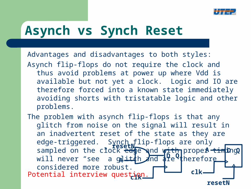
Asynch vs Synch Reset
Advantages and disadvantages to both styles:
Asynch flip-flops do not require the clock and thus avoid problems at power up where Vdd is available but not yet a clock. Logic and IO are therefore forced into a known state immediately avoiding shorts with tristatable logic and other problems.
The problem with asynch flip-flops is that any glitch from noise on the signal will result in an inadvertent reset of the state as they are edge-triggered. Synch flip-flops are only sampled on the clock edge and with proper timing will never “see” a glitch and are therefore considered more robust.
Potential interview question.resetN
D QA
clk
resetN
D QA
clk

Synthesis effects
always @(posedge clk)
if (reset) A <= 0;
else A <= E && C;
Always block with posedge clk statement is sequential but can include some input combinatorial logic as shown.
ED Q
C
clk

Synthesis effects
module p2s (in, out, load, clk, reset)
input load, clk, reset;
input [7:0] in;
output out;
reg [7:0] parallel_data;
wire out = parallel_data[7];
always @(posedge clk)
if (reset) parallel_data <= 0;
else if (load) parallel_data <= in;
else parallel_data <= {parallel[6:0], 1’b0};
endmodule
Shift register for parallel to serial conversion –
susceptible to hold time violations

Hold Time Violation Review
D Q
clk1
d1 = 1D Q
d3d2
clocktree
clk2
Good case:No clock skewd2 1 -> 0d3 0 -> 1
Bad case:12ns clock skewd2 1 -> 0d3 0 -> 0
Caused by clock skewSinister problemCannot fix with frequencyClock synthesis and balancing
very important

Synthesis effects - Latches
always @(clk or in) //unusual but intentional latch
if (clk) A = in;
else A = A;
always @(*) // typical unintentional latch
if (enable) A = in;
always @(*) // intentional combinatorial mux
if (enable) A = in1;
else A = in2
Always block with posedge clk statement is sequential.
This example will result in a transparent latch. Very unusual in RTL.
Typically, latches in the synthesized netlist are the sign of mistakes.

Examples – rolling average
always @(posedge clk)average <= average[15:0] +
{{8{data_input[15]}}, data_input[15:8]} – {{8{average[15]}}, average[15:8]};
average = average + (1/256) * data_input – (1/256) * average
Handles signed inputs
Examples – parallel to serial
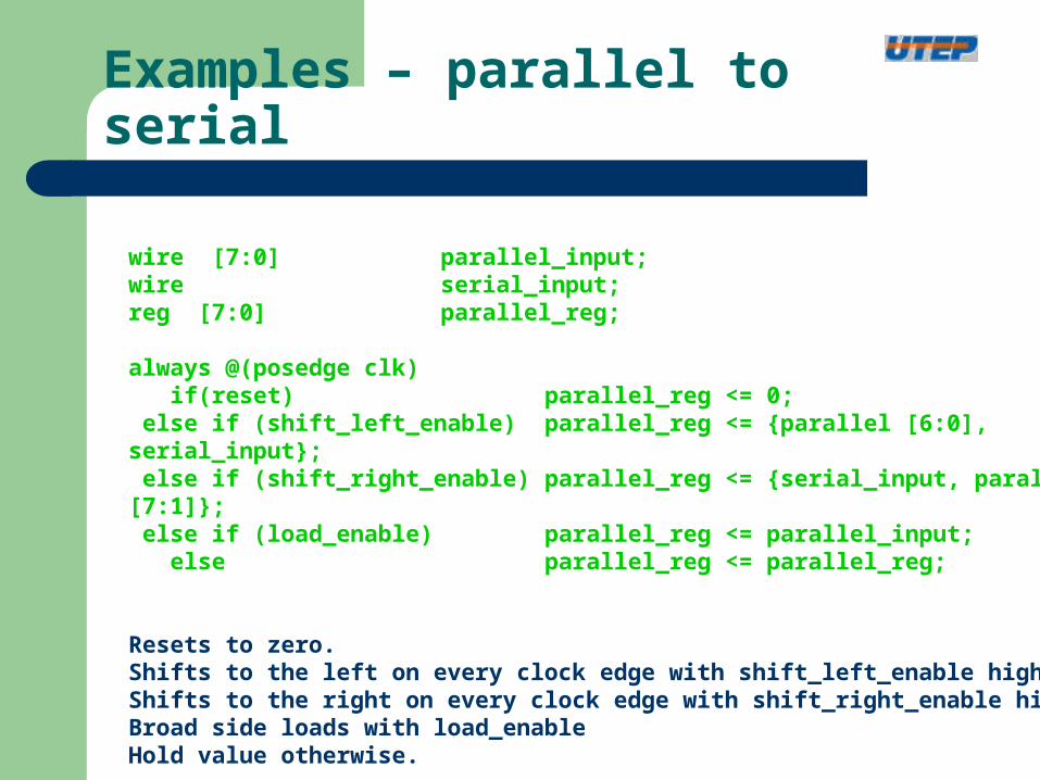
wire [7:0] parallel_input;wire serial_input;reg [7:0] parallel_reg;
always @(posedge clk) if(reset) parallel_reg <= 0; else if (shift_left_enable) parallel_reg <= {parallel [6:0], serial_input}; else if (shift_right_enable) parallel_reg <= {serial_input, parallel [7:1]}; else if (load_enable) parallel_reg <= parallel_input; else parallel_reg <= parallel_reg;
Resets to zero.Shifts to the left on every clock edge with shift_left_enable high.Shifts to the right on every clock edge with shift_right_enable high.Broad side loads with load_enableHold value otherwise.

Examples – signed multiplier
reg [15:0] pre_p;reg [15:0] product;wire [7:0] aN = a[7] ? (~a + 1) : a;wire [7:0] bN = b[7] ? (~b + 1) : b;
always @(a or b or aN or bN) if(~b[7] && ~a[7]) pre_p = a * b; else if (a[7] && ~b[7]) pre_p = aN * b; else if (~a[7] && b[7]) pre_p = a * bN; else pre_p = aN * bN;
wire [15:0] pre_pN = pre_p[7] ? (~pre_p + 1) : pre_p;
always @(a or b or aN or bN) if(~b[7] && ~a[7]) product = pre_p; else if (a[7] && ~b[7]) product = pre_pN; else if (~a[7] && b[7]) product = pre_pN; else product = pre_p;

Xilinx Spartan FPGA Logic Architecture

Four input Look Up Table (LUT) to provide logic function.
Example: Y = A*B + C*DABCD Y0000 00001 00010 00011 10100 00101 00110 00111 11000 01001 01010 01011 1 1100 11101 11110 11111 1
Bypassable flip-flop to select sequential or combinatorial logic
Xilinx Spartan FPGA Logic Architecture
Bit file includes LUT contents, select values for all muxes and the interconnect information between all of the slices

Xilinx Synthesis
1) 18 by 18 bit multipliers available / identified automatically2) Block RAM – available if instantiated in code
causes compatibility problems with ASICs 3) Digital Clock Manager – available if instantiated in code
causes compatibility problems with ASICs allows for clock frequency multiplication

Xilinx Synthesis
////////////////// Clock Generation///////////////////////////////////////wire dcm_locked;wire [7:0] dcm_status;
DCM DCM (.CLKIN ( clk ), .RST ( ~sys_reset ), .PSEN ( 1'b0 ), // don't use phase shifter.CLKFB ( 1'b0 ), // not using DLL.PSINCDEC ( 1'b0 ), // unused phase shifter.PSCLK ( 1'b0 ), // unused phase shifter .LOCKED ( dcm_locked ), .STATUS ( dcm_status ),.CLKFX ( capture_clk ),.CLKFX180 ( ));
defparam DCM.CLKFX_MULTIPLY = SAMPLE_MULTIPLE;defparam DCM.CLKFX_DIVIDE = 1;

Xilinx Synthesis
// xilinx ram block - 512 x 32 + 4 bits parityRAMB16_S36 capture_memory (
.CL ( capture_clk ),
.EN ( ~cen ),
.WE ( ~wen ),
.SSR ( 1'b0 ),
.DIP ( 4'b0 ),
.DOP ( ),
.DO ( capture_memory_out ),
.DI ( {8'b0, current_d, current_d} ),
.ADDR ( address ));

Verilog Design Guidelines
Avoid “begin” and “end” in synthesizable code for clarity Use meaningful names for signals and variables Use “I_” and “O_” for port names – I for input / O for output Modify regs in only one always block Constants and Parameters should be all caps Never use tabs but do line up text with spaces Avoid mixing positive and negative edge-triggered flip-flops Use parentheses to optimize logic structure Use continuous assign statements for simple combo logic. Use non-blocking for sequential and blocking for combo logic Define if-else/case statements explicitly – all vars for all cases Always instantiate modules with explicit port listing.

Most common student mistakes
Synthesizable code should– not have delays included (#)– only have always blocks and no initial blocks
Define a reg in only one always block (otherwise ambiguity) for loops are for spatial repeating - not temporal Fully specify variables within an always block for readability
– i.e. if (X) Y = A, else Y = B. Define Y in all possible cases.– this may result in unwanted latches (as opposed to flip-flops)
Fully specify sensitivity list in combinatorial always blocks Blocking vs. Non-blocking assignments
– rule of thumb if it has a posedge, use the “<=“ because it is sequential otherwise use the “=“ because it is combinational Really doesn’t matter if you only define a single variable in a block

Examples of problem code
always @(C or D or S or E)
begin
if (S) begin
A = D;
B = C;
end;
else A = E;
end
BAD
always @(C or D or S or E or F)
if (S) begin
A = D;
B = C;
end
else begin
A = E;
B = F;
end
BETTER
In any always block, define all variables for all cases.
Not doing so can cause latches and in general is hard to follow.
Furthermore, should have one always block per reg for clarity.
always @(D or S or E)
if (S) A = D;
else A = E;
always @(C or S or E)
if (S) B = C;
else B = F;
BEST
Examples of problem code
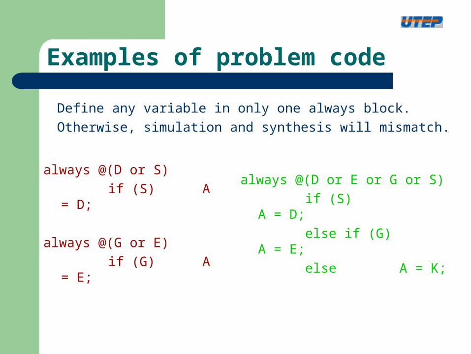
always @(D or S)
if (S) A = D;
always @(G or E)
if (G) A = E;
always @(D or E or G or S)
if (S) A = D;
else if (G) A = E;
else A = K;
Define any variable in only one always block.
Otherwise, simulation and synthesis will mismatch.

Examples of problem code
always @(D or S or K or
J or E or C or G )
begin
if (S) A = D;
else if A = J;
else A = K;
if (G) B <= E;
else B <= C;
end
always @(D or E or G or S)
if (S) A = D;
else if A = J;
else A = K;
always @(G or E or C)
if (G) B = E;
else B = C;
Define only one if-else statement per always block.
Define only one reg per always block.
Better to have one block for each variable and one variable per block.

Examples - problem code - Clocks
The traditional methodology works best using a single universal clock
1) negedges are discouraged as they make clock balancing difficult
D Q
clk
D Q
clocktree
D Q
D Q

Examples - problem code - Clocks
The traditional methodology works best using a single universal clock
2) additional clocks make static timing less effective
- any large design will have several clock domains, but each
new clock adds complications
- can’t time paths that traverse clock domains
- asynchronous domains can cause metastability
Multiple clocks are unavoidable but should be handled with care
D Q
Q’
D Q
Q’
D Q
Q’
metastableclean
synchronized signal
clk1 clk2
data_dest
data_src logic path

Examples - problem code - Clocks
The traditional methodology works best using a single universal clock
3) data signals should never be used as clocks (with posedge)
- could be noisy and cause spurious edges
- makes static timing ineffective
D Q
Q’
D Q
Q’
D Q
Q’
This is a non-synchronous ripper counter – very fast, small and efficient. However data is used as clock and is therefore this type of design is not allowed in most ASIC and FPGA methodologies

Reference
Verilog 2001 Standard – new features added– port list and input/output declarations combined– sensitivity lists in always blocks need not be listed
Good reference web pages for Verilog– www.deepchip.com– opencores.com– www.edacafe.com– www.cadence.com original company
www.synopsys.com most used synthesis tool
– www.mentor.com commonly used simulator– www.magma-da.com new synthesis tool– www.altera.com FPGA company– www.xylinx.com FPGA company