vermont yankee nuclear power...
TRANSCRIPT

September, 2014
Vermont Yankee Nuclear Power Station
Radiological Historical Site Assessment
Entergy Nuclear Operations, Inc.Vermont Yankee Nuclear Power Station
320 Governor Hunt RoadVernon, Vermont 05354
Prepared by:
Radiation Safety & Control Services91 Portsmouth Avenue
Stratham, NH 03885-2468

September, 2014
VYNPS Radiological Historical Site Assessment Page 2 of 31
Table of Contents
Glossary of Terms, Acronyms and Abbreviations ...................................................... 4Executive Summary ...................................................................................................... 61.0 Purpose .................................................................................................................. 82.0 Property Identification ........................................................................................... 8
2.1 Physical Characteristics ............................................................................... 92.2 Environmental Setting .................................................................................. 9
3.0 Historical Site Assessment Methodology .......................................................... 133.1 Approach and Rationale ............................................................................. 133.2 Documents Reviewed ................................................................................. 143.3 Property Inspections .................................................................................. 143.4 Personnel Interviews .................................................................................. 15
4.0 Historical and Current Use .................................................................................. 154.1 History ......................................................................................................... 154.2 Description of Circumstances Impacting Site Radiological Status ......... 16
5.0 Assessment Findings .......................................................................................... 175.1 Contaminants .............................................................................................. 175.2 Environmental Radioactivity ...................................................................... 175.3 Contaminated Media ................................................................................... 185.4 Non-Impacted Areas ................................................................................... 185.5 Impacted Areas ........................................................................................... 18
6.0 Impacted Buildings and Structures .................................................................... 186.1 Class 1 Buildings and Structures .............................................................. 186.2 Class 2 Buildings and Structures .............................................................. 206.3 Class 3 Buildings and Structures .............................................................. 21
7.0 Soil and Groundwater Impacts ................................................................... 227.1 Impacted Site Soil ....................................................................................... 227.2 Groundwater Monitoring (Radiological and Non-radiological) ................ 26
8.0 Summary and Conclusions ................................................................................. 299.0 References ........................................................................................................... 31

September, 2014
VYNPS Radiological Historical Site Assessment Page 3 of 31
List of Tables
Table 1 Summary of Radiological Conditions of Interest ........................................... 1Table 2 Preliminary Classification of the Radiological Status of Plant Buildings,Structures and Site Soil ................................................................................................ 1
List of Figures
Figure 1 Preliminary Classification of the Radiological Status of Plant Buildingsand Structures ............................................................................................................... 1Figure 2 Map “A” Showing Areas of Radiological Conditions of Interest ................. 1Figure 3 Map “B” Showing Areas of Radiological Conditions of Interest ................. 1

September, 2014
VYNPS Radiological Historical Site Assessment Page 4 of 31
Glossary of Terms, Acronyms and Abbreviations
ANR – Agency of Natural ResourcesAOG – Augmented Off Gasbgs – below ground surfaceBWR – Boiling Water ReactorCAB- Containment Access BuildingCo – CobaltCOB – Construction Office BuildingCSM – Conceptual Site ModelCST – Condensate Storage TankCs - CesiumDCGL - Derived Concentration Guideline LevelDP - Decommissioning PlanDPR – Decommissioning Planning RuleDQOs – Data Quality ObjectivesDSAR - Defueled Safety Analysis ReportENVY- Entergy Nuclear Vermont YankeeFe - IronFSAR - Final Safety Analysis ReportFSS – Final Status SurveyGPI – Groundwater Protection InitiativeH – Hydrogen or TritiumHSA - Historical Site AssessmentHVAC-Heating, Ventilation, Air ConditioningISFSI - Independent Spent Fuel Storage InstallationLLD – Lower Limit of DetectionMARSSIM - Multi-Agency Radiation Survey and Site Investigation ManualMDA – Minimum Detectable ActivityMn – ManganeseMW – Mega WattNEI - Nuclear Energy InstituteNi - NickelNRC - Nuclear Regulatory CommissionODCM - Offsite Dose Calculation ManualPSB – Plant Support BuildingPu – PlutoniumRB – Reactor BuildingRCA - Radiologically Controlled AreaREMP – Radiological Environmental Monitoring ProgramRHSA – Radiological Historical Site AssessmentRRCs – Recognized Radiological ConditionsRW – Radioactive WasteRWB – Radioactive Waste BuildingSAFSTOR - Safe StorageSr – Strontium

September, 2014
VYNPS Radiological Historical Site Assessment Page 5 of 31
SSCs – Systems, Structures and ComponentsTB – Turbine BuildingV&V – Verification and ValidationVYNPS – Vermont Yankee Nuclear Power StationZn – Zinc

September, 2014
VYNPS Radiological Historical Site Assessment Page 6 of 31
Executive Summary
The radiological historical site assessment was completed in accordance with theguidance provided in NUREG-1575 (MARSSIM). As expected, operational activities atVYNPS have resulted in areas that have been impacted with radiological contaminants.Events and conditions that resulted in radioactive contaminants being deposited inlocations outside of buildings and structures are attributed to spills, leaks, effluentreleases and build up over time of residual contamination that could not be detected bymonitoring methods in use at the time. No impacted areas were identified that were notpreviously known or documented.
Events and conditions were investigated upon discovery and appropriate actions takento terminate/secure the leaks or stabilize and/or eliminate the condition. Remediationwas initiated if required to prevent migration of contamination and minimize impact tothe environment. No identified areas of radiological contamination are a current orexpected threat to human health, the environment, or appear to present a significantchallenge for decommissioning.
The dominant plant-related radioactive contaminants identified in the Protected andOwner-Controlled areas are cobalt-60 (Co-60), cesium-137 (Cs-137) and tritium (H-3).Additional radionuclides such as manganese-54 (Mn-54), zinc-65 (Zn-65), iron-55 (Fe-55), cesium-134 (Cs-134) and strontium-90 (Sr-90) were identified in samples collectedat the Northeast side of the Radwaste Building and from soil borings beneath thechemistry lab sinks.
Areas designated as non-impacted include the Plant Support Building (PSB), the powerup-rate building (PUB), several smaller ancillary buildings within the Owner ControlledArea and the Entergy-owned property outside the Owner Controlled Area.
Impacted areas include buildings and structures, soil and groundwater. The locations ofthe impacted areas are confined to the Protected and Owner Controlled Areas. Allareas and structures have been given a preliminary classification based on availableradiological characterization data, knowledge of historical site operations and results ofpersonnel interviews.
Buildings, structures, systems and components associated with nuclear poweroperations and handling of related radioactive material that are located within theRadiologically Controlled Area (RCA) are designated as Class 1 areas. This includesbuildings such as Reactor, Turbine, Radwaste, Condensate Storage Tank andassociated structure, parts of the Service Building, Containment Access andAugmented Off-Gas Buildings.
In Class 2 buildings and structures, the potential for residual contamination exists.Buildings and structures designated as Class 2 include the North Warehouse, PlantStack and Maintenance Machine Shop. The potential for low levels of residualcontamination may exist in Class 3 areas. The classification of Class 3 buildings and

September, 2014
VYNPS Radiological Historical Site Assessment Page 7 of 31
structures include the Control Building, South Warehouse, Construction Office Building,Cooling Towers and the Intake and Discharge Structures.
As a result of plant operations, soil has been impacted by spills, leaks and plantactivities. Categories of impacted soil areas include:
· Storm drain system· Septic system· Underground pipes· Surface soil areas
Impacted soil (environmental) areas that are outside of buildings and structures and aredesignated as Class 1 include:
· Underground pipe leak at AOG Building· Buildup of contamination on the Northeast side of the Radwaste Building
(contaminated soil near cask room doors)· Chemistry lab drain line leak (10 CFR 20.2002 NRC approved disposal in place)· Condensate Storage Tank spill and tank bottom leak· North and South Storm Drain Systems, Outfall and River Sediments
accumulation of building roof and site runoff
Areas that have been known to contain residual radioactivity are designated as Class 2;examples of Class 2 soil areas include:
· Concentration of low levels of contamination in septic system sludge (10 CFR20.2002 NRC approved disposal in South Field Application Area)
· Sand blast media from maintenance work near the south side of the NorthWarehouse
· Cask loading activities impacting soil adjacent to the Radwaste Building· Storage and handling of radioactive materials impacting surface soil adjacent to
the North Warehouse
Areas of potential residual radioactivity are designated as Class 3; examples of Class 3soil areas include:
· Septic leach fields and tanks· Cooling tower silt and temporary storage areas (10 CFR 20.2002 NRC approved
disposal of cooling tower silt in South Field Application Area)· Former burn area for wood scraps· Former storage area for asbestos and plowed snow
Groundwater monitoring programs in place to meet regulatory guidance and permitrequirements has detected tritium resulting from the underground leaking pipe in thepipe trench located near the AOG building. No plant generated radionuclides have everbeen detected in groundwater samples from the South Field Application Area (10 CFR20.2002 licensed disposal area for septic sludge and soil) or within the septic leach fieldareas.

September, 2014
VYNPS Radiological Historical Site Assessment Page 8 of 31
1.0 Purpose
The purpose of this report is to summarize the radiological historical site assessment ofthe VYNPS, the “subject property”, located at 320 Governor Hunt Road in Vernon,Vermont. The objective is to assess the potential for the presence of recognizedradiological conditions of concern at this location. This report assesses whether currentor past activities at the subject property have created such conditions and the potentialimpact of these conditions on the decommissioning process. This document focuses onpotential radiological contamination of the VYNPS. A separate document has beenprepared to identify and evaluate potential non-radiological contamination of the site.
The VYNPS Training Center and Emergency Response Center are located at 185 OldFerry Road in Brattleboro, Vermont. These properties plus the company-ownedproperties adjacent to VYNPS along Governor Hunt Road are not included in thisassessment.
2.0 Property Identification
The subject property, commonly known as Vermont Yankee Nuclear Power Station(VYNPS), is a 125-acre parcel located on Governor Hunt Road in the town of Vernon,Windham County, Vermont.
Construction of the single 540 megawatt (MW) Boiling Water Reactor (BWR) plantbegan in 1967. Commercial operation began on November 30, 1972. The stationpower output was increased to 650 MW in 2006.
The following information further identifies the subject property:
Address: 320 Governor Hunt Road, Vernon, Vermont
County: Windham
Property owners: Entergy Nuclear Vermont Yankee, LLC (ENVY)
USGS Quadrangle: Brattleboro, Vermont
Latitude, Longitude: 42º46’43.97” North, 72º30’50.36” West
Zoning: Industrial
Lister’s Map: Map No. 36 Lot No. 21
Year Built: 1967–1972 Main Power Station Buildings1985 Construction Office Building1985 Containment Access Building1981 New Warehouse Building1998 Plant Support Building

September, 2014
VYNPS Radiological Historical Site Assessment Page 9 of 31
2.1 Physical Characteristics
The property is divided into the Protected Area and the Owner Controlled Area. TheProtected Area is completely enclosed by a high security double chain-link fencesystem that is subject to electronic surveillance and monitored by security personnel 24-hours per day. Buildings located within the Protected Area of the property include theReactor Building (RB), the Turbine Building (TB), the North and South Warehouses, theContainment Access Building (CAB), Advanced Off-Gas Building (AOG), the RadwasteBuilding (RWB), the Maintenance Building, the Control Room Building, theAdministration Building, the Construction Office Building (COB), the New Warehouse,and various small storage sheds and outbuildings.
The Owner Controlled Area comprises all the property outside the Protected Area, andis completely enclosed by a chain-link perimeter fence. Access by vehicular traffic isgained through Gate 1 off of Governor Hunt Road. Buildings located within the OwnerControlled Area of the property include the Plant Support Building (PSB), the Shippingand Receiving Building, the Power Up-rate Building (PUB), four temporary buildingsstoring turbine rotors and casings, the 115kV and 345kV switchyards and VELCOsubstation and small storage sheds and outbuildings.
The area adjacent to the power station buildings and the parking lots are paved withasphalt and the surrounding land is covered with grass, shrubs and trees. In addition tothe fences around the Protected Area and the Owner Controlled Area, a fence has beenerected on the west side of the property owned by VYNPS, on the line parallel to therear (east) plot lines of the properties on Governor Hunt Rd. This land is farmed on aregular basis.
VYNPS and properties in the power station’s vicinity are served by privately-ownedwater and sewer systems. Figure 1 is a site plan showing the layout of the powerstation and its buildings.
2.2 Environmental Setting
The subject property is located on the west shore of the Connecticut River, immediatelyupstream of the Vernon Hydroelectric Station. The property is bounded on the north,west, and southwest by privately-owned land and on the east and south by theConnecticut River.
2.2.1 Geological Setting
The geology of the subject property has been described during previous investigationscompleted at the site. The first investigation was completed in 1966 by Goldberg-Zoinoand Associates, Inc. (GZA) for siting of the power station (Reference 1). A secondstudy was a detailed hydrogeological investigation completed in 1988 by Wagner,Heindel & Noyes (WHN), for the siting of a proposed low-level radioactive waste

September, 2014
VYNPS Radiological Historical Site Assessment Page 10 of 31
repository (Reference 2). A third investigation was completed in 1991 by Battelle, inconjunction with Hanson, Shannon & Wilson and WHN, and was a comprehensive sitecharacterization to determine the feasibility of land application of low-level radioactivewaste in the North Field portions of the subject property (Reference 3). A fourthinvestigation was completed in 2001 by Environmental Compliance Services, Inc.,immediately prior to purchase of the subject property by Entergy, to identify areas of theproperty where petroleum and /or hazardous materials may have been released to thesoil or groundwater (Reference 4). A fifth investigation was completed in 2011 by GZAGeoEnvironmental, Inc., to investigate the occurrence of tritium in groundwater at thesubject property (Reference 5). The following discussion of geology and hydrology isreproduced from Reference 5.
2.2.1.1 Surficial Geology
VYNPS (the “Site”) is located in an area of lowlands and river terraces that spanapproximately one mile in width and border the Connecticut River. These lowlands aresituated between bedrock-controlled upland areas to the east and west of the river. Theaverage local relief is up to several hundred feet. The overburden geology is typical ofglacial river valleys. The Site is underlain by soils typical of glaciolacustrine deposits,ice-contact stratified drift or outwash, scattered till deposits, and floodplain deposits (i.e.sand, silt and gravel, with some clayey zones) over bedrock consisting of hard biotitegneiss.
The region of the Site is located within the footprint of the Laurentide ice sheet, which atits maximum reached south of the current shoreline of the states of Connecticut andRhode Island. As the climate warmed and the ice sheet retreated northward, largevolumes of sand and gravel were deposited into the Connecticut River Valley. In thearea of Rocky Hill, Connecticut these deposits, referred to as the Rocky Hill dam,blocked the flow of surface water in the Connecticut River Valley, and as water becameimpounded between this sediment and the retreating ice margin, Glacial Lake Hitchcockwas formed. The lake grew slowly as the ice sheet continued to melt and retreat, withthe lake’s maximum extent reaching as far north as St. Johnsbury, Vermont. Eventuallythe Rocky Hill dam was breached and Glacial Lake Hitchcock drained, leaving behindextensive glaciolacustrine sediments in the Connecticut River Valley.
The Site is situated within the historic extent of Glacial Lake Hitchcock. Mappedsurficial geology for the area indicates lacustrine and littoral sediments, described aspredominantly well-sorted sand and pebbly sand. This material is typical of thatdeposited along the shoreline of the lake as fast-flowing water from tributaries flowingoff the valley margins or along the retreating and melting glacial front entered the calmlake region.
The geology within the Site vicinity includes approximately 10 to 70 feet of glaciallydeposited soils overlying bedrock. The overburden geology is typical of glacial rivervalleys, with the soils consisting of sand, silt and gravel. Occasional pockets of clay

September, 2014
VYNPS Radiological Historical Site Assessment Page 11 of 31
have been encountered in depressions in the bedrock surface. Individual strata withinthe sand deposit are generally relatively uniform in nature, as is common for glacialstream deposits, and range from loose fine sand to dense coarse sand with a trace ofsilt. In general, the sand increases in density with depth. Some potentiallydiscontinuous fine-grained deposits (silt layers) also appear to be present in areas ofthe Site.
A number of gravel pits are found on terraces along the eastern side of the hills west ofthe Site, which form the western boundary of the river valley. These areas are mappedas being underlain by gravel lake shore deposits on upland terraces that run roughlynorth-south. Higher up on the hills exposed and minimally covered bedrock is common.East of the ridges, wooded sloped areas transition into a valley of more level farm landwhere the Site is located.
2.2.1.2 Bedrock Geology
The Site is located within the Brattleboro syncline, part of the Connecticut Valley-GaspeSynclinorium. This region is underlain by Paleozoic age metamorphic rocks. The areacontains a band of Triassic age sedimentary rock to the south of the Site inMassachusetts. Foliated igneous rocks of middle and late Devonian age underlie alarge portion of the region. The Site is located over a fairly large pluton of the OliverianMagma Series known as the Vernon Dome, which is comprised generally of gneissgrading from a light gray to pinkish-gray, slightly to moderately foliated, medium-grainedgranodiorite (quartz-diorite) to granite. This pluton extends over an area approximately8 miles long and 2 miles wide, striking approximately 10 degrees to the northwest anddipping steeply to the east.
2.2.2 Hydrology
The Site is located on the west bank at approximately mile 138 upstream from themouth of the Connecticut River. At this location, the river is formed into a reservoir(often referred to as Vernon Pond) above the TransCanada Corporation’s VernonStation Hydroelectric Dam. As a result, the surface elevation of the Connecticut River iswell regulated adjacent to the Site.
The Connecticut River flows generally from north to south. It is the most significantdrainage feature in the region, and local streams ultimately discharge to the river. Inaddition to variations in rainfall and snow melt, the flow of river water is largelydetermined by the operation of dams and hydroelectric stations, including the VernonDam and several upstream and downstream facilities. River stage data indicate that thesurface water elevation in the river adjacent to the Site typically ranges fromapproximately 217 to 220 feet above the North American Vertical Datum of 1988 (NAVD88).
2.2.2.1 Groundwater Levels and Flow Directions
The local water table fluctuates depending on the amount of precipitation and level

September, 2014
VYNPS Radiological Historical Site Assessment Page 12 of 31
changes in the Connecticut River. River flooding may cause a temporary, localizedreversal in the normal groundwater flow direction toward the river, resulting in riverwater flowing into river bank soils.
At the Site, groundwater is present within the glacial deposits overlying the bedrock(also known as the overburden) at depths ranging from approximately 5 to 30 feet belowground surface (bgs). Groundwater generally flows from the west to the east toward theConnecticut River. In 1988 and 1989, and again in 2007 and 2010, groundwatermonitoring well networks were installed across the Site to monitor groundwater qualityand elevations. Groundwater levels in the northern portion of the Site (where thesurface elevation is approximately 260 feet NAVD 88) vary between approximately 5and 18 feet bgs. In the vicinity of the major VYNPS plant structures (the “power block”),where the surface elevation is approximately 252 feet NAVD 88, groundwater has beenobserved to be about 20 to 30 feet bgs. Along the southern portion of the Site, wherethe surface elevation is approximately 260 feet NAVD 88, depth to groundwater isapproximately 30 feet bgs.
The area in the vicinity of the VYNPS plant is primarily farm and pasture land with muchof the surrounding region undeveloped and wooded. Residences, the Vernon TownOffice Building and the Vernon Elementary School are located along Governor HuntRoad to the west of the Site. The school, the town offices, most residences and theVYNPS plant are served by private water-supply wells drilled into the bedrock beneaththe overburden. Some residences located along Governor Hunt Road have shallowwater supply wells for domestic use.
2.2.2.2 Groundwater Recharge and Discharge
Groundwater recharge is comprised of the net precipitation (minus runoff andevapotranspiration) that infiltrates the ground and contributes to groundwater flow withina watershed. Areas of recharge exist in the upland portion of the watershed west of theSite and on unpaved portions of the river terrace deposits within the valley in which theSite is located. Due to the relatively steep grades and low permeability of thesubsurface materials in the upland areas to the west of the Site (primarily bedrock andglacial till), a relatively high amount of the precipitation that falls on this area runs off,resulting in a relatively low amount of infiltration to the water table there (groundwaterrecharge). Water that does infiltrate in upland areas primarily will recharge theunderlying fractured bedrock. On unpaved portions of the river terrace deposits in thelower portions of the river valley, where slopes are flatter and permeabilities are greater,a relatively greater amount of infiltration and lesser amount of surface runoff results inrelatively more groundwater recharge.
September, 2014
VYNPS Radiological Historical Site Assessment Page 13 of 31
3.0 Historical Site Assessment Methodology
The Historical Site Assessment (HSA) is the first step in a process described in NUREG-1575, “Multi-Agency Radiation Survey and Site Investigation Manual” (MARSSIM)(Reference 6). The purpose of MARSSIM is to provide a standardized approach todemonstrating compliance with a dose or risk-based regulation. MARSSIM providesguidance to prepare and implement a statistically valid survey and site investigationplan that will support termination of the NRC operating license for a licensed facility.
3.1 Approach and Rationale
The primary tasks in the MARSSIM survey and site investigation process are:
· Historical Site Assessment· Scoping Survey· Characterization Survey· Remedial Action Support Survey· Final Status Survey· Regulatory Agency Confirmation and Verification
This document is focused on the initial steps in what is an iterative process in whichknowledge about the site is continuously gained by reviewing past events andconditions and conduct of scoping and characterization surveys.
Historical Site AssessmentThe intent of an HSA is to document a comprehensive investigation that identifies andevaluates historical information pertaining to events and conditions that may haveresulted in contamination during the operating history of the subject site. Contaminantsof interest include both radiological and non-radiological, and may have impactedsystems, structures or components (SSCs) of the plant or environmental media withinthe owner-controlled property. The information developed by the HSA is evaluated todifferentiate impacted from non-impacted areas of the site. Areas determined to beimpacted are further classified (based on preliminary information) as Class 1, Class 2 orClass 3, depending upon the apparent severity of their impact.
As defined in NUREG-1575, Class 1 areas are those that have, or had prior toremediation, a potential for radioactive contamination (based on site operating history)or known contamination (based on previous radiation surveys) at concentrations greaterthan the release criteria. Examples of Class 1 areas include: 1) site areas previouslysubjected to remedial actions, 2) locations where leaks or spills are known to haveoccurred, 3) former burial or disposal sites, 4) waste storage sites, and 5) areas withcontaminants in discrete solid pieces of material and high specific activity.

September, 2014
VYNPS Radiological Historical Site Assessment Page 14 of 31
Class 2 areas are those that have, or had prior to remediation, a potential for radioactivecontamination or known contamination, but not at concentrations expected to exceedthe release criteria. To justify changing the classification from Class 1 to Class 2, thereshould be measurement data that provides a high degree of confidence that noindividual measurement would exceed the release criteria. Examples of areas thatmight be classified as Class 2 include: 1) locations where radioactive materials werepresent in an unsealed form, 2) potentially contaminated transport routes, 3) areasdownwind from stack release points, 4) upper walls and ceilings of buildings or roomssubjected to airborne radioactivity, 5) areas handling low concentrations of radioactivematerials, and 6) areas on the perimeter of former contamination control areas.
Class 3 areas are any impacted areas that are not expected to contain any residualradioactivity, or are expected to contain levels of residual radioactivity at a small fractionof the release criteria, based on site operating history and previous radiation surveys.Examples of areas that might be classified as Class 3 include buffer zones aroundClass 1 or Class 2 areas, and areas with very low potential for residual contaminationbut insufficient information to justify a non-impacted classification.
Class 1 areas have the greatest potential for contamination and, therefore, receive thehighest degree of survey effort using a graded approach, followed by Class 2, and thenby Class 3. Non-impacted areas do not receive any level of survey coverage becausethey have no potential for residual contamination.
3.2 Documents Reviewed
Historical information was reviewed and compiled into the HSA to identify areas wherecontamination existed, remains or has the potential to exist. This information includedinterviews of long-tenured employees, spill reports, radiological incident files, specialsurvey and operational survey records, the VYNPS file maintained in compliance with10CFR 50.75(g), VYNPS Radioactive Effluent Release Reports, VYNPS AnnualRadiological Environmental Monitoring Reports, and a Phase I and II EnvironmentalSite Assessment report of the VYNPS (Reference 4). Each identified radiological areaof interest is listed in Table 1.
3.3 Property Inspections
Aerial photographs, station walk downs and information gathered from personnelinterviews were used to establish the current condition of systems, structures andcomponents as well as environmental areas at VYNPS.
In general, there has been a progressive increase in the number of structures andswitchyards within the Protected Area and the Owner Controlled Area since operation ofthe station began in 1972. The outlying properties beyond the Owner Controlled Area
September, 2014
VYNPS Radiological Historical Site Assessment Page 15 of 31
are relatively unaffected by site operations and have remained open farm land withunrestricted use since construction of the facility began.
3.4 Personnel Interviews
Interviews of current or former long-time employees of VYNPS were conducted duringApril and May 2014. The intent of the interviews was to provide a means of identifyingareas where either radiological or non-radiological contamination may have occurredbut that may not have been documented in plant records. Employees who were atVYNPS for many years, particularly during plant construction and early operation, weresought because spill reporting and documentation of contamination incidents then maynot have been as complete as they have become more recently. For example, federalregulation 10 CFR 50.75(g), which requires compilation of records of contaminationincidents that may have significance during decommissioning, did not exist prior to1988. Therefore, incidents that occurred prior to approximately 1988 may have beendocumented but those records may not appear in the 10 CFR 50.75(g) file and may notbe easily found.
Nine (9) individuals with an average length of employment at the plant of 36 years wereinterviewed; most began employment at VYNPS during the years 1967 to 1972 and hadfirst-hand experience during plant construction.
In general, results of the interviews corroborated information developed by recordsearches and plant tours, and did not identify any Class 1 areas that had not beenidentified by other lines of investigation. A common comment was that intervieweeswere not aware of incidents that were not reported and recorded. It was theirexperience that their co-workers generally followed procedures and performed theirduties to the best of their ability. Several of the interviewees also stressed thatemployees at the plant were very conscientious of their responsibility to identifysignificant issues and ensure that they were properly addressed and reported tomanagement.
4.0 Historical and Current Use
Consistent with the guidance of NUREG-1575 (MARSSIM) (Reference 6), andRegulatory Guide 4.22 “Decommissioning Planning During Operations” (Reference 7),the HSA evaluated information regarding historical facility operation, regulatoryinvolvement, permits and licenses, and waste handling procedures.
4.1 History
Central Vermont Public Service (CVPS) purchased the initial parcel of farm land for theVYNPS site. CVPS and several other New England utilities contracted with YankeeAtomic Electric Company (YAEC) to build the 540 Megawatt (MW), General Electric,boiling water reactor.

September, 2014
VYNPS Radiological Historical Site Assessment Page 16 of 31
Construction was started in 1967 and the plant became fully operational in 1972 underthe management of YAEC and CVPS. In the late 1970’s Vermont Yankee NuclearPower Corporation (VYNPC) was established and successfully operated and managedthe facility until 2002 when the facility was sold to Entergy Nuclear Vermont Yankee,LLC.
In 2006 the permitted power output was increased to 650 MW. In 2011 the U.S. NRCgranted the plant a 20-year license extension (from 2012 until 2032). In 2013 Entergyannounced that the plant would be closing at the end of 2014.
4.2 Description of Circumstances Impacting Site Radiological Status
Normal plant operations are expected to result in contamination of certain areas of thesite (mainly buildings and structures); these areas were designed to contain suchmaterial. During operations, certain events and conditions have resulted in radioactivematerial being deposited in other locations. As a result, the plant design andoperational procedures evolved to accommodate or eliminate these circumstances.
The following events and circumstances generally contributed to the various aspects ofresidual contamination found in areas outside of the buildings and structures.
· Leaks from tanks, chemistry lab drains and underground piping to theenvironment
· Build up over time of low levels of contamination in soil adjacent to buildings· Surface water runoff from building roofs and paved areas to adjacent soil and
storm drain systems· Build up over time from activities associated with packaging and transport of
radwaste· Concentration of low levels of contamination in septic system tank bottoms· Build up over time of fallout/washout of routine plant effluents· Build up over time from storage and handling of radioactive materials
From the research described in Subsections 3.2, 3.3 and 3.4 above, areas of interestwere identified as potentially impacted by radioactive contamination that may havesignificance during decommissioning. None of the areas identified are considered to bean imminent threat to human health or the environment, or appear to present asignificant challenge to the decommissioning process. Table 1 lists the areas ofinterest; the map locations listed in Table 1 refer to the areas shown on Figure 1, Figure2 (“Map A”) and Figure 3 (“Map B”).
Each radiological condition of interest listed in Table 1 has been assigned a preliminaryclassification, as described in MARSSIM. Site-specific derived concentration guidelinelevels (DCGLs) for VYNPS have not been determined; therefore, the preliminaryclassifications in Table 1 are only an estimate of the relative magnitude of radiologicalcontamination that may now exist in an area of interest. In some areas, (for example

September, 2014
VYNPS Radiological Historical Site Assessment Page 17 of 31
the station gatehouses) the classification is based solely on knowledge of plantoperations rather than radiological sampling and analysis. In other areas (for examplethe soil beneath the Chemistry Lab floor) the classification is based on previousradiological characterization surveys that may have been completed many years in thepast.
Events and conditions were investigated upon discovery and appropriate actions takento terminate/secure the leaks or alleviate the condition. Remediation was initiated ifrequired to prevent migration and minimize impact to the environment. Some incidentsof contamination were not completely remediated at the time of discovery because 1)the source of contamination was removed and residual contaminant concentrationswere very low, 2) screening data indicated that the contaminant levels detected did notpresent a risk to human health or the environment, 3) the contamination was containedand managed within a structure, 4) the contamination was inaccessible, and/ or 5) thecontaminants are not mobile in soil.
5.0 Assessment Findings
Most issues identified were the result of spills, leaks, or accumulated concentration overtime of contaminating material that was released from the facility at levels less thanthose that could be detected by real-time monitoring methods employed at the facility.Those monitoring methods at the time were state-of-the-art and comparable to methodsused throughout the nuclear industry.
5.1 Contaminants
The dominant plant-related radioactive contaminants identified in the Protected andOwner-Controlled areas are cobalt-60 (Co-60), cesium-137 (Cs-137) and tritium (H-3).Additional radionuclides such as manganese-54 (Mn-54), zinc-65 (Zn-65), iron-55 (Fe-55), cesium-134 (Cs-134) and strontium-90 (Sr-90) were identified in samples collectedat the Northeast side of the Radwaste Building and from soil borings beneath thechemistry lab sinks.
5.2 Environmental Radioactivity
Radionuclides present in the environmental background are both naturally occurringand man-made. Carbon-14 is introduced cosmogenically and by the atmospherictesting of nuclear weapons. Tritium is also introduced cosmogenically and throughatmospheric detonation of nuclear weapons. Cesium-137 and strontium-90 are fissionproducts that occur in the environment as a result of atmospheric nuclear weapondetonations and international nuclear accidents (Chernobyl and Fukushima- Daiichi). Astudy completed in 1999 by Duke Engineering and Services (Reference 8) quantifiedthe background concentrations of Cs-137 in surface soils and sediments in theBrattleboro, VT region.

September, 2014
VYNPS Radiological Historical Site Assessment Page 18 of 31
5.3 Contaminated Media
Contaminated media include primarily soil, groundwater, concrete and steel. Relativelysmall volumes of other construction materials such as paint, insulation, rubber, glass,asphalt, etc., may be found to be contaminated during detailed radiological surveys ofvarious areas of the plant. Septage from the sewage systems within the Protected Areaof the station may be slightly contaminated. Additionally, some components such asInterim Off-Gas system (IOG) filters, pipes conveying radioactive liquids or gases andthe leach field laterals potentially may be contaminated.
5.4 Non-Impacted Areas
The non-impacted areas include the Plant Support Building (PSB), the power up-ratebuilding (PUB), several smaller ancillary buildings within the Owner Controlled Area andthe Entergy-owned property outside the Owner Controlled Area. A more complete list ofnon-impacted areas is provided in Table 2.
5.5 Impacted Areas
The impacted areas include buildings, structures, soil and groundwater. The locationsof the impacted areas are confined to the Protected and Owner Controlled Areas.Table 1 contains a list of potential areas of interest.
6.0 Impacted Buildings and Structures
All areas and structures have been given a preliminary classification based on availableradiological characterization data, knowledge of historical site operations, and results ofpersonnel interviews. The classification of an area or subsection of an area may berevised when new radiological sample data become available. Tables 1 and 2 contain asummary of all buildings and structures on site at the time this HSA was developed andtheir preliminary classifications.
6.1 Class 1 Buildings and Structures
All buildings, structures, systems, and components associated with the VYNPS nuclearpower reactor or associated with handling of related radioactive material are Class 1areas as they are defined in MARSSIM (Reference 6). The areas listed below arelocated within the RCA. These areas have been designated as Class 1 because theyare very likely to contain radioactive contamination at concentrations greater than thelicense termination criteria. Remediation of this contamination will require removal anddisposal of radioactive waste at an NRC-licensed disposal facility if the VYNPS site is tobe released for unrestricted use from its operating license issued by the U.S. NRC.

September, 2014
VYNPS Radiological Historical Site Assessment Page 19 of 31
Reactor Building
The Reactor Building encloses the primary reactor system, primary containment, reactorprimary and auxiliary cooling systems, reactor refueling pool, dryer and separator pool,and spent fuel storage pool. The building provides secondary containment for thereactor and primary containment for auxiliary systems. Primary containment for thereactor consists of the drywell and the pressure suppression chamber (Torus).
Turbine Building
The Turbine Building houses the turbine generator and associated auxiliaries, includingthe condensers, feedwater system, and condensate water treatment system. Otherauxiliary equipment is also located in this building, such as emergency dieselgenerators, house heating boilers, the water pre-treatment room and the machine shop.
Radwaste Building
The Radwaste Building contains systems designed to treat radioactive water forrecycling back to the plant and the equipment to process solid waste for shipment anddisposal off site. The building also houses the Fuel Pool demineralizers for maintainingthe Fuel Pool chemistry. The area east of the Radwaste Cask room was discovered tobe contaminated in 1987. This contamination was caused by leakage from the Caskroom during the cask wash-down process. The area was cleaned sufficiently to insurethe safety of the station personnel and procedures and processes were modified suchthat the potential for future contamination was greatly reduced.
Condensate Storage Tank and Associated Structure
The Condensate Storage Tank building is adjacent to the condensate storage tank andis part of the moat that surrounds the tank. The building contains valves, piping andinstrumentation associated with the operation of the tank. Approximately 83,000 gallonsof water from this tank leaked to the Connecticut River through electrical penetrations inthe moat and the South Storm Drain System 1976. Also, in 1986 a leak developed inthe bottom of the tank. Corrective actions involved replacing the bottom of the tank,upgrading the moat and routing the discharge from the sump in the moat to theRadwaste Building to prevent future unmonitored release to the river by this pathway.
Service Building
The Service Building contains the access to the RCA, and includes the Chemistry Lab,count rooms, decontamination showers, and the Health Physics Check Point. Theremainder of the building primarily consists of office space. A leak from a drain linefrom the chemistry laboratory sinks to the Radwaste Building was discovered to havereleased radionuclides to the soil beneath the lab floor in 1991. VYNPS submitted a 10CFR 20.2002 application to the NRC to allow the contamination to remain in place. Theapplication was approved on July 10, 1992.

September, 2014
VYNPS Radiological Historical Site Assessment Page 20 of 31
Containment Access Building
The Containment Access Building is primarily a very large empty building. The mainfunction of the building is to provide shelter for moving equipment and material,including new fuel assemblies and radioactive waste casks, in and out of the ReactorBuilding. Radioactive material stored in the building is sealed such as to prevent thespread of contamination. Occasionally, large quantities of radioactive material,including new and spent fuel assemblies, are moved through this building
Advanced Off-Gas Building
The Advanced Off-Gas building houses the hydrogen recombiners, two charcoal guardbeds, dryers, flame arrestor, the main hold up charcoal filters and associated pipingsystems. The general purpose of the AOG system is to reduce the release of short half-life radioactive gasses to the environment. This is accomplished by recombining thecombustible gasses and passing the remaining non-combustible radioactive gassesthrough a series of pipes and charcoal beds. The process “holds up” or “delays” thesegasses, allowing most of the radioactive material to decay before discharging it to theenvironment. When the plant is shut down, there will be very little residual radioactivematerial left in the system. The exception will be the charcoal beds, including the guardbed and the main bed. These filters will have measurable amounts of Cs-137 trappedin the charcoal. Once the charcoal is removed, there should be only trace amounts ofradioactive material remaining.
6.2 Class 2 Buildings and Structures
Class 2 areas are likely to contain measurable concentrations of radioactivecontamination, but not at levels expected to be greater than the DCGLs. Majorbuildings presumed to be Class 2 are listed below.
North Warehouse
The North Warehouse is located inside the Protected Area and is used to store wasteoil awaiting shipment off site for disposal, various pieces of radiologically contaminatedequipment and other waste items including spent lead-acid batteries, used ethyleneglycol and small PCB-containing components. The radioactive waste packages arestored in the east end of the building when they are ready to ship. This building alsohoused a waste oil furnace that was formerly used to burn slightly radioactivecontaminated oil for several years.

September, 2014
VYNPS Radiological Historical Site Assessment Page 21 of 31
Plant Stack
All of the air from the HVAC systems in the main buildings is discharged from the stationthrough the plant stack. Additionally, the Standby Gas Treatment System, the GlandSeal Exhaust and the Advanced Off-Gas System exhaust through the Plant Stack. Theassociated piping for these systems runs underground from the plant to the stack. Lowpoint drains from these pipes also run underground to the Radwaste Building.
Maintenance Machine Shop
The maintenance machine shop is where components from within the RCA are servicedand repaired. The shop is located in the south end of the Turbine Building and containsequipment normally associated with a well-equipped machine shop. The shop is part ofthe RCA and contains the radioactive materials tool crib. When radioactive componentsare worked on in the shop, a “containment” is established around the work area and isdecontaminated after the job is completed.
6.3 Class 3 Buildings and Structures
Class 3 areas may have measurable concentrations of radioactive contamination, but ifpresent, it is presumed to be at levels that are a small fraction of the DCGLs. The majorbuildings and structures presumed to be Class 3 are listed below. Additional smallerbuildings presumed to be Class 3 are listed in Table 2.
Control Building
The Control Building contains the control room from which the turbine, reactor andassociated ancillary systems are operated. The building also houses the cable vaultand the two switch gear rooms.
South Warehouse
The South Warehouse is located inside the Protected Area and is used to store drumsof virgin lubricants and motor oils. Radioactive material was never used or stored in thefacility.
Construction Office Building
The Construction Office Building is located inside the Protected Area and containsoffices and a cafeteria for plant workers. Radioactive material was never used or storedin this facility.
Cooling Towers
The Cooling Towers (2) are located outside of the Protected Area. They include thepipes, fans, baffles and collection pools that comprise a system for cooling thecirculating water from the plant main condenser. Trace amounts of radioactive material

September, 2014
VYNPS Radiological Historical Site Assessment Page 22 of 31
generated by the plant have been measured in the silt collected from the deep basin ofthe west cooling tower. Therefore, there is the potential that areas of the system wheresilt may collect may also contain trace amounts of radioactive material.
Intake Structure
The Intake Structure is located at the northeast corner of the Protected Area and drawscooling water from the Connecticut River through the Circulation Water Bay for use inthe Circulation Water System that cools the plant main condenser. The structure alsohouses the Service Water pumps, the Fire pumps and the Radioactive Waste dilutionpumps. These pumps draw water from the Service Water Bay to supply theirassociated systems. The Radioactive Waste dilution pumps were used infrequentlyearly in the life of the station and then not used after 1981. Trace amounts ofradioactive material generated by the plant have been measured in silt in the river bedupstream of the intake structure near the North Storm Drain outfall. Therefore, there isthe potential that the Circulation Water Bay and the Service Water Bay may accumulatesilt that contains trace amounts of this same activity.
Discharge Structure
The Discharge Structure is located immediately outside of the southeast corner of theProtected Area and discharges cooling water that has passed through the plant maincondenser or the cooling towers. The structure houses the pumps that send water tothe cooling towers when operation of the towers is required. Trace amounts ofradioactivity that may have collected in these systems have been detected in the riversilt near the Discharge Structure.
7.0 Soil and Groundwater Impacts
As a result of site operations, soil and groundwater have been impacted by spills, leaksand plant activities. In accordance with the requirements of the NRC DecommissioningPlanning Rule (DPR), licensees of operating facilities are required to minimizecontamination and generation of radioactive waste, conduct appropriate radiologicalsurveys including of the subsurface, maintain records of residual radioactivity, andprovide adequate funding to complete decommissioning. Specific guidance iscontained in Regulatory Guide 4.22, “Decommissioning Planning During Operations”(Reference 7). VYNPS has been satisfying the intent of the requirements includingimplementation of the Groundwater Protection Initiative (GPI) for subsurface monitoring.
7.1 Impacted Site Soil
Impacted soil areas are have been categorized as:· Storm Drain Systems· Septic Systems· Underground Pipes

September, 2014
VYNPS Radiological Historical Site Assessment Page 23 of 31
· Surface soil areas
The following sections have summarized some of the information gathered from thereview of plant records. Table 1 contains a summary of impacted soil areas on site atthe time this HSA was developed and their preliminary classifications.
7.1.1 Class 1 Areas- Areas of Potentially Elevated Residual Radioactivity
· Soil outside of a pipe trench in the vicinity of the Augmented Off-Gas (AOG)Building became contaminated due to a pipe leak identified in January 2010.The area between the Maintenance Shop and the AOG Building was excavatedand the leak was stopped. Approximately 85 cubic yards of soil was removed aspart of the remediation. The two drains lines that were leaking were isolated andabandoned following the installation of new lines. The excavated area wasbackfilled with flowable concrete material and clean soil from an off-site source.The groundwater was also impacted and is discussed in section 7.2. Additionalinformation on this event can be found in Item # 7, Table 1.
· In 1991, a leak was discovered in the drain line from the chemistry lab sinks tothe chemical drain tank in the Radwaste Building. This leak contaminated thesoil under the concrete floor of the lab. Soil borings were analyzed and resultsindicated the presence of radiological contamination. This area has beendesignated as an approved on-site waste disposal area under the therequirements of NRC regulation 10 CFR 20.2002. The groundwater surface inthis area of the station is below the bedrock surface and the soil between the labfloor and the underlying bedrock is not saturated, as evidenced by the fact thatno groundwater entered a monitoring well installed at the location of the leak.Additional information on this event can be found in Item# 8 of Table 1.
· Soil adjacent to the Northeast side of the Radwaste Building was contaminatedby build-up of low level radioactivity associated with activities to packageexpended resin for transport to a disposal facility. The contaminated soil nearestthe cask room doors was analyzed for levels of radioactivity and subsequentlyexcavated, backfilled, and sealed with asphalt in August 1987. Further samplingof this area to better characterize the extent of soil contamination performed inMay of 1988, indicated the presence of contamination at levels lower than thosefound in 1987. Therefore, no additional soil was removed. A pathway doseassessment of this area was completed. The contaminated soil is not a concernfor on-site or off-site doses. Additional sampling was performed at theboundaries of this area in 1999 and results indicate the contamination has notspread beyond the original identified boundary. Additional information on thisevent can be found in Item# 14 of Table 1.
· In 1976, 83,000 gallons of CST water was released to the Connecticut River froman overflow pipe over a 2-day period via electrical conduit from the CondensateStorage Tank Moat, which eventually flowed to the South Storm Drain System.This was documented in NRC Report No: RO-76-22/1T. In addition, in 1986 aleak was discovered in the bottom of the tank that had saturated the sand layer

September, 2014
VYNPS Radiological Historical Site Assessment Page 24 of 31
between the tank bottom and the underlying concrete support structure.Additional information on this event can be found in Item# 35 of Table 1.
· North and South Storm Drain Systems, Outfall and River Sediments- During theearly years of operation, the Turbine and Admin Building Heating, Ventilation andAir Conditioning (HVAC) exhausts went to the roof vents. Contaminationaccumulated over time on the roofs and in other areas of the site and throughweathering, migrated via runoff to the storm drain systems. Tritium was detectedintermittently in manholes and a discrete particle of Co-60 was detected in the siltin the river near the area of the North Storm Drain outfall. The Turbine Buildingand Admin exhausts were redirected to the plant stack in 1993. River sedimentsampling is conducted two times a year in accordance with the ODCM and theongoing Radiological Environmental Monitoring Program (REMP) to ensure thesafety of the public and to protect the environment. Information on the stormdrain system contamination is included in the Annual Radiological EnvironmentalOperating Report. Additional information on this condition can be found in Items#1, 2, 3 and 4 of Table 1.
7.1.2 Class 2 Areas- Areas that Have Been Known to Contain ResidualRadioactivity
· In 1983, a pile of contaminated sand-blasting media was discovered near thesouth side of the North Warehouse. This material had been generated duringmaintenance work associated with a previous refueling outage. The materialwas discovered on an unpaved portion of the Protected Area. The media waspackaged and disposed of as radioactive waste. The affected area wasexcavated and all contaminated soil was disposed of as radioactive waste.Subsequent samples collected in this area have shown only trace amounts ofradioactivity. Additional information on this event can be found in Item# 16 ofTable 1.
· The cask loading activities impacting the soil adjacent to the Radwaste Buildingdescribed in Section 7.1.1 have resulted in low level contamination migrating toan area adjacent to the Intake structure. Additional information on this event canbe found in Item# 15 of Table 1.
· Storage and handling of radioactive materials in the North Warehouse resulted inlow level contamination of the surface soil adjacent to the North Warehouse.Additional information on this event can be found in Items# 17 and 18 of Table 1.
· In June 1988, plant septage was found to contain low levels of Co-60 and Cs-137. All off-site septage shipments were halted immediately. The issue ofresidual contamination in septic tanks and leach fields is not unique to VYPNS;this is a recognized industry-wide concern prompting issue of NRC Bulletin 80-10(contamination of a nonradioactive system). VYNPS submitted a 10 CFR 20.302application (now 10 CFR 20.2002) to the NRC which was approved on 8/30/89.These regulations pertain to a method for obtaining NRC approval for a proposeddisposal method. The application and approval to spread the septage on theNorth and South Application Fields are in Appendix B of the ODCM; to date only

September, 2014
VYNPS Radiological Historical Site Assessment Page 25 of 31
the South Application Field has been used. When the septic tanks are pumpedthe sludge is sampled, analyzed and spread in the South Field Application Area.Additional information on this event can be found in Item# 5 of Table 1.
7.1.3 Class 3 Areas- Areas of Potential Residual Radioactivity
· The area between the Cooling Towers has been used for temporary storage ofsilt removed from the Deep Basin of the West Cooling Tower and soil excavatedduring modification of the Protected Area. This material was spread in the SouthField Application Area in accordance with an NRC approved 10 CFR 20.2002application. Additional information on this condition can be found in Item# 60 ofTable 1.
· The soil area north of the main parking lot was previously used to storecontaminated asbestos and snow was routinely piled in this area from plowingthe Protected and Owner Controlled Area parking lots. Low levels ofcontamination may have accumulated in this area. Additional information on thiscondition can be found in Item # 63 of Table 1.
· Wood scraps were burned on-site during the late 1970s in the North parking lot.The material was surveyed and released from the plant using monitoringtechniques that were in accordance with industry standards at the time. Thesemonitoring techniques may have resulted in release of trace amounts ofradioactive material which was concentrated in the burn process resulting inmeasurable low levels of contamination in the burn area. Sampling wascompleted in this area in 2001 and a monitoring well was installed. The area wasalso sampled and remediated during construction of the new VELCO substationand adjacent parking lot. Additional information on this condition can be found inItem # 64 of Table 1.
· The Spray Pond is located south of the Protected Area, north of the CoolingTowers. Since December 2004, silt removed from the West Cooling Tower DeepBasin that contains trace amounts of radioactivity is temporarily stored in thespray pond before being spread in the South Field Application Area. Additionalinformation on this condition can be found in Item # 61 of Table 1.
· In 1993, low levels of contamination were found in the silt removed from the deepbasin under the West Cooling Tower. The source of the silt is cooling waterwithdrawn from the Connecticut River. Every 18 months, the Deep Basin isinspected and if necessary, additional silt is removed. VYNPS submitted anamendment to the 10 CFR 20.2002 application for spreading of septic sludge, toalso allow spreading of the cooling tower silt on the same 2-acre South FieldApplication Area where the septic sludge is spread. That amended applicationwas approved by the NRC on 6/18/97. Additional information on this event canbe found in Item# 58 of Table 1.
· Currently there are a number of septic systems serving the various buildings inthe Protected and Owner Controlled Areas that collect waste from the lavatories,showers, kitchens and janitorial facilities. The associated leach fields receive theliquid portions from the septic tanks. Groundwater from monitoring wells in each

September, 2014
VYNPS Radiological Historical Site Assessment Page 26 of 31
leach field and effluent are sampled and analyzed for tritium and gamma-emittingradionuclides semiannually. No radioactivity has been detected in thesesamples. However, when the septic tanks are pumped, the sludge is sampled,analyzed and spread in the South Field Application Area in accordance with theNRC approved 10 CFR 20.2002 application as discussed in Item #5 of Table 1.Additional information on septic leach fields can be found in Item #6 of Table 1.
7.2 Groundwater Monitoring (Radiological and Non-radiological)
7.2.1 Groundwater Monitoring ProgramsGroundwater monitoring programs have been developed to meet various regulatoryguidance and permit requirements. The key programs include:
· Groundwater Protection Initiative in accordance with Nuclear Energy Institute’s(NEI 07-07) (Reference 9); the program is currently designed for operatingplants.
· The Radiological Environmental Monitoring Program (REMP) monitorsgroundwater used for drinking water.
· Groundwater monitoring to meet permit requirements for the septic tank sludgeand septic leach field permits.
After VYNPS ceases operation, the technical bases of the groundwater monitoringprograms will continue to be evaluated throughout the phases of decommissioning toensure groundwater monitoring is commensurate with the activities and conditions ofthe station.
VYNPS implemented NEI 07-07 as part of a fleet-wide effort to comply with theGroundwater Protection Initiative (GPI). This program was first implemented inNovember 2007 when three monitoring wells were drilled at locations along the easternboundary of the site to screen for the presence of radionuclides in groundwater downgradient from the plant. Tritium was detected in a groundwater sample collected inNovember 2009 from one of these wells. A comprehensive hydrogeologicalinvestigation was commenced in January 2010 to determine the source, fate andtransport of the tritium. Twenty nine (29) additional groundwater monitoring wells weredrilled at the site during that investigation to characterize the hydrogeological flowdomain and allow collection of groundwater samples.
In addition to groundwater from the 31 monitoring wells routinely sampled as part of theGroundwater Protection Initiative (NEI 07-07), groundwater from other wells is sampledas part of the VYNPS Radiological Environmental Monitoring Program (REMP). Thesewells include two on-site potable water wells producing drinking water from the bedrockaquifer west of the protected area. A third well, the Southwest Well, also taps into thebedrock aquifer but is no longer used as a potable water well. Water from theSouthwest Well is also sampled quarterly in compliance with the Vermont YankeeOffsite Dose Calculation Manual (ODCM).

September, 2014
VYNPS Radiological Historical Site Assessment Page 27 of 31
Septic tank sludge (septage) is periodically land spread in the South Field ApplicationArea in accordance with a Vermont Agency of Natural Resources (VANR) permit forresiduals management and an NRC septage spreading permit under federalregulation 10 CFR 20.2002, as outlined in Appendix B of the VY Off-Site DoseCalculation Manual (ODCM). Four shallow wells, located adjacent to the South FieldApplication Area are sampled quarterly for gross beta activity, gamma-emittingradionuclides and tritium. No plant-generated radionuclides have ever been found in thesamples from these wells.
Groundwater from approximately 21 shallow monitoring wells distributed within sixseptic leach field areas located in various parts of the plant and septic system effluentfrom the three systems within the Protected Area are sampled semi-annually. Thesamples are analysed by a contract laboratory for indicators of biological impacts,including E. coli, chloride, nitrate, sulfate, phosphorus and pH, in accordance with theVYNPS Indirect Discharge Permit issued by the Vermont Agency of Natural Resources.The sample results from each location are in compliance with the permit requirements.Although not required by the permit, groundwater and effluent samples are analyzed forradioactivity by the VYNPS on-site Chemistry Laboratory before shipment off-site foranalysis by the contract lab. No plant-generated radionuclides have ever been found inthe samples from these wells.
7.2.2 Summary of Groundwater Impacts
The known impacts to groundwater at VYNPS can be summarized asfollows:
· Tritium is the only plant-generated radionuclide detected in groundwater atthe site. In 2010, a comprehensive hydro-geologic investigation of the sitewas completed and found tritium in shallow groundwater extendingapproximately 400 feet down-gradient from the source at the AOG Buildingpipe chase to the Connecticut River. The width of the tritium plumeincreases from approximately 100 feet at the source area to approximately300 feet along the bank of the river. Tritium concentrations in the shallowsand aquifer have rapidly decreased at the source area from approximately2,500,000 pCi/L in February 2010 when the leak was terminated to lessthan 2,000 pCi/L in April 2010. Similar attenuation has also occurred withinthe shallow plume down-gradient of the source, as the center of the residualcontaminant mass migrates to the east. Attenuation is occurring at a slowerrate in a deeper silt sand aquifer and an intervening silt aquifer where thehydraulic conductivities and related seepage rates are lower.
· No tritium, gamma-emitting or hard-to-detect radionuclides have beenidentified in groundwater from any wells in other areas of the plant, includingthe drinking water wells located west of the Turbine Building, the REMP wellsand the wells in the six septic system leach field areas. The one exception

September, 2014
VYNPS Radiological Historical Site Assessment Page 28 of 31
is the Construction Office Building (COB) well located at the northeast cornerof the COB and within the area of the tritium plume. The COB well was one offour drinking water supply wells for the plant that produce water from thebedrock aquifer. Low levels (approximately 2,000 picocuries/liter) of tritiumwere detected in the COB well during the investigation of the leak from theAOG Building pipe chase however; this test was deemed invalid due to thetest conditions resulting in shallow groundwater being pulled down into theCOB bedrock well. The COB well has since been permanently abandonedand filled with a cement grout to reduce the potential for drawing tritium intothe bedrock aquifer.
· No non-radiological impacts to groundwater related to the permitted disposalof sanitary wastewater in on-site septic system leach fields or spreading ofseptic system sludge in the South Land Application Area have been detectedby groundwater monitoring in these areas. No data points are available toevaluate the impact to groundwater (if any) that may have resulted from theleak in the chemistry laboratory sink drain discovered in 1991, or from fires atthe Main Transformer (in 2004) and the Auxiliary Transformer (in 1973) thatreleased transformer oil on the ground beyond their containment structures.
· Non-radioactive contamination of groundwater was identified in 1994 whenthe 5,000-gallon underground storage tank containing fuel oil for the househeating boiler was found to be leaking and was removed. Free-phase fuel oilwas detected in 2 of 9 monitoring wells installed during the investigation andremediation of the leak. A buried fill pipe for the 5,000-gallon tank that runsmore than 200 feet from the fuel oil pump room near the 75,000-gallon mainfuel oil storage tank failed a tightness test after the tank was removed. The fillpipe was blanked off but not removed because overlying buildings made itinaccessible. In 2008 the Vermont Department of EnvironmentalConservation issued a finding of “site management activities complete”regarding the tank leak, although low levels of fuel oil constituents andsolvents were still detectable in nearby monitoring wells. The source of thesolvents was likely a dry cleaning operation formerly located in the nearbyTurbine Building truck bay during the mid-1980s. Impacts to soil beneath theTurbine Building truck bay or along the buried fuel oil fill pipe that were notinvestigated because these areas are effectively inaccessible.
· It should be noted that the four underground storage tanks containing fuel oilor diesel fuel that are currently on site are double-walled, with electronicinterstitial leak monitoring. The above-ground tanks storing petroleumproducts are either double-walled or within concrete containment

September, 2014
VYNPS Radiological Historical Site Assessment Page 29 of 31
structures. Similarly, transformers with large oil capacities are located withinconcrete containment structures or are on concrete pads with a perimeterconcrete berm. These design features reduce the likelihood ofgroundwater contamination caused by a release from these transformers.
8.0 Summary and Conclusions
The radiological historical site assessment was completed in accordance with theguidance provided in NUREG-1575 (MARSSIM). As expected, operational activities atVYNPS have resulted in areas that have been impacted with radiological contaminants.Events and conditions that resulted in radioactive contaminants being deposited inlocations outside of buildings and structures are attributed to spills, leaks, effluentreleases and build up over time of residual contamination that could not be detected bymonitoring methods in use at the time. No impacted areas were identified that were notpreviously known or documented.
Events and conditions were investigated upon discovery and appropriate actions takento terminate/secure the leaks or stabilize and/or eliminate the condition. Remediationwas initiated if required to prevent migration of contamination and minimize impact tothe environment. No identified areas of radiological contamination are a current orexpected threat to human health, the environment, or appear to present a significantchallenge for decommissioning.
The dominant plant-related radioactive contaminants identified in the Protected andOwner-Controlled areas are cobalt-60 (Co-60), cesium-137 (Cs-137) and tritium (H-3).Additional radionuclides such as manganese-54 (Mn-54), zinc-65 (Zn-65), iron-55 (Fe-55), cesium-134 (Cs-134) and strontium-90 (Sr-90) were identified in samples collectedat the Northeast side of the Radwaste Building and from soil borings beneath thechemistry lab sinks.
Areas designated as non-impacted include the Plant Support Building (PSB), the powerup-rate building (PUB), several smaller ancillary buildings within the Owner ControlledArea and the Entergy-owned property outside the Owner Controlled Area.
Impacted areas include buildings and structures, soil and groundwater. The locations ofthe impacted areas are confined to the Protected and Owner Controlled Areas. Allareas and structures have been given a preliminary classification based on availableradiological characterization data, knowledge of historical site operations and results ofpersonnel interviews.
Buildings, structures, systems and components associated with nuclear poweroperations and handling of related radioactive material that are located within theRadiologically Controlled Area (RCA) are designated as Class 1 areas. This includesbuildings such as Reactor, Turbine, Radwaste, Condensate Storage Tank and

September, 2014
VYNPS Radiological Historical Site Assessment Page 30 of 31
associated structure, parts of the Service Building, Containment Access andAugmented Off-Gas Buildings.
In Class 2 buildings and structures, the potential for residual contamination exists.Buildings and structures designated as Class 2 include the North Warehouse, PlantStack and Maintenance Machine Shop. The potential for low levels of residualcontamination may exist in Class 3 areas. The classification of Class 3 buildings andstructures include the Control Building, South Warehouse, Construction Office Building,Cooling Towers and the Intake and Discharge Structures.
As a result of plant operations, soil has been impacted by spills, leaks and plantactivities. Categories of impacted soil areas include:
· Storm drain system· Septic system· Underground pipes· Surface soil areas
Impacted soil (environmental) areas that are outside of buildings and structures and aredesignated as Class 1 include:
· Underground pipe leak at AOG Building· Buildup of contamination on the Northeast side of the Radwaste Building
(contaminated soil near cask room doors)· Chemistry lab drain line leak (10 CFR 20.2002 NRC approved disposal in place)· Condensate Storage Tank spill and tank bottom leak· North and South Storm Drain Systems, Outfall and River Sediments
accumulation of building roof and site runoff
Areas that have been known to contain residual radioactivity are designated as Class 2;examples of Class 2 soil areas include:
· Concentration of low levels of contamination in septic system sludge (10 CFR20.2002 NRC approved disposal in South Field Application Area)
· Sand blast media from maintenance work near the south side of the NorthWarehouse
· Cask loading activities impacting soil adjacent to the Radwaste Building· Storage and handling of radioactive materials impacting surface soil adjacent to
the North Warehouse
Areas of potential residual radioactivity are designated as Class 3; examples of Class 3soil areas include:
· Septic leach fields and tanks· Cooling tower silt and temporary storage areas (10 CFR 20.2003 NRC approved
disposal of cooling tower silt in South Field Application Area)· Former burn area for wood scraps· Former storage area for asbestos and plowed snow

September, 2014
VYNPS Radiological Historical Site Assessment Page 31 of 31
Groundwater monitoring programs in place to meet regulatory guidance and permitrequirements has detected tritium resulting from the underground leaking pipe in thepipe trench located near the AOG building. No plant generated radionuclides have everbeen detected in groundwater samples from the South Field Application Area (10 CFR20.2002 licensed disposal area for septic sludge and soil) or within the septic leach fieldareas.
9.0 References
1. Vermont Yankee Nuclear Project Geology Report, Goldberg-Zoino andAssociates, Inc., October 1966
2. Vermont Yankee Hydrogeologic Study, An Investigation of a Proposed LowLevel Radioactive Waste Repository Site, Wagner, Heindel and Noyes, Inc.,September 1988
3. Site Characterization Data Report for the Vernon/Vermont Yankee Site,Battelle; Hanson, Shannon and Wilson, Inc.; and Wagner, Heindel andNoyes, Inc., November 1991
4. Phase I & II Environmental Site Assessment, Vermont Yankee NuclearPower Corporation, Environmental Compliance Services, Inc., June 2001
5. Hydrogeologic Investigation of Tritium in Groundwater, Vermont YankeeNuclear Power Station, GZA GeoEnvironmental, Inc., May 2011
6. NUREG – 1575, Rev 1, “Multi-Agency Radiation Survey and SiteInvestigation Manual (MARSSIM)”, U.S. Nuclear Regulatory Commission,U.S. Environmental Protection Agency, U.S. Department of Energy, andU.S. Department of Defense, August, 2000
7. Regulatory Guide 4.22, “Decommissioning Planning During Operation”, U.S.Nuclear Regulatory Commission, December 2012
8. Determination and Application of Background Cesium-137 Concentrationsto Various VYNPS Soils and Sediments, Duke Engineering & Services,March 31, 1999
9. NEI 07-07, Industry Groundwater Protection Initiative-Final GuidanceDocument, Nuclear Energy Institute, August, 2007
10. BVY 97-101, Report to the NRC and the Vermont Department of Health ofdetection of a Co-60 hot particle at the North Storm Drain Outfall
11. BVY 10-039, Report to the NRC and the Vermont Department of Health ofthe tritium leak at the AOG pipe chase

September, 2014
VYNPS Radiological Historical Site Assessment Page 1 of 23
Table 1 Summary of Radiological Conditions of Interest
No. AreaFigure No. /
MapLocation
Current ConditionPrelimClass(1, 2or 3)
Justification forPreliminary
Classification
Storm Drain Systems
1 North StormDrainSystem
2 / A-1 The system was sampled extensively in 1993. Twomanholes, 11E and 11F, were sampled monthly forsediment analyses. Tritium was detected intermittently. Thetritium was condensed from the air in the Turbine andAdministration Buildings. HVAC exhaust from thesebuildings was redirected to the plant stack in late 1993.Manholes MH-12A (North Storm Drain) and 14 (SouthStorm Drain) are sampled monthly for tritium but none hasbeen detected since redirection of the HVAC exhaust.Starting in September 2001 most manholes are inaccessiblebecause they have been welded shut due to securityconcerns. Extensive sampling of the storm drain systemswas done in the summer of 1999. VYNPS has completedan evaluation pursuant to 10 CFR 50.59 (a regulationcontrolling changes, tests and experiments by nuclear plantlicensees) on both the North and South Storm DrainSystems. Information on the storm drain systemcontamination is included in the Annual RadiologicalEnvironmental Operating Report.
1 Detection of adiscrete particle ofCo-60 in the silt inthe river near thearea of the NorthStorm Drain outfall.

September, 2014
VYNPS Radiological Historical Site Assessment Page 2 of 23
No. AreaFigure No. /
MapLocation
Current ConditionPrelimClass(1, 2or 3)
Justification forPreliminary
Classification
2 North StormDrain Outfalland RiverSediments
2 / A-2 andA-3
A sample in 1997 contained a discrete particle of Co-60 of3,820 pCi. This detection was reported to the NRC in BVY97-101(Reference 10). The source of the particle was likelywashout of the Turbine Building HVAC exhaust that formerlydischarged to the Turbine Building roof but was redirectedto the Plant Stack in late 1993. The roof was replaced in theearly 2006. Samples of river sediment are collected froman area along the shoreline 80 ft by 160 ft. This sampling isdone two times per year as required by the VYNPS ODCM.Recent sampling results are only showing trace levels ofCs-137 and sporadic low level detections of Co-60. A doseassessment of the Co-60 particle concluded that this areaposes no risk to human health, as reported in BVY 97-101.The ongoing radiological environmental monitoring program(REMP) is designed to detect and monitor any buildup ofradioactivity in the environment from plant activities.
2 Detection of adiscrete particle ofCo-60 in the silt inthe river near thearea of the NorthStorm Drain outfall.
3 South StormDrainSystem
2 / A-4 The system was sampled extensively in 1993. Tritium isdetected sporadically in the South Storm Drain System. MH-14 is currently sampled weekly for tritium. There was onepositive tritium value in 1998 (900 pCi/l) in MH-14. All othersamples were <700 pCi/l. This is a recognized NRCBulletin 80-10 issue (contamination of a nonradioactivesystem). Extensive sampling of the storm drain systemswas done during the summer of 1999. VYNPS hascompleted an evaluation pursuant to 10 CFR 50.59 (aregulation controlling changes, tests and experiments bynuclear plant licensees) on both the North and South StormDrain Systems. Information on the storm drain systemcontamination is included in the Annual RadiologicalEnvironmental Operating Report.
1 This systemreceives much ofthe storm waterfrom the stationpower block andMH-12 receivesstorm water fromthe Radwaste CaskLoading Area.

September, 2014
VYNPS Radiological Historical Site Assessment Page 3 of 23
No. AreaFigure No. /
MapLocation
Current ConditionPrelimClass(1, 2or 3)
Justification forPreliminary
Classification
4 Manhole 12 2 / A-4 Manhole 12 is in the South Storm Drain System and is closeto the Radwaste Cask Loading Area (A-5 on Figure 2). Thesediment is sampled monthly. Typically, there is very littlesediment available for sampling. Monitoring of this manholebegan in February 1988.
1 Proximity to theRadwaste CaskLoading Area.
Septic Systems
5 SepticSystemSludge
3 / B-1 In June 1988, VY determined that the plant septagecontained Co-60 and Cs-137. All off-site septage shipmentswere halted immediately. This is a recognized NRC Bulletin80-10 issue (contamination of a nonradioactive system).VYNPS submitted a 10 CFR 20.302 application (now 10CFR 20.2002) to the NRC which was approved on 8/30/89.10 CFR 20.302 has been superseded by 10 CFR 20.2002.Both regulations pertain to a method for obtaining NRCapproval for a proposed disposal method. The applicationand approval to spread the septage on the North and SouthApplication Fields are in Appendix B of the ODCM. Thematerial is spread only on the 2-acre South Field ApplicationArea. Sampling data demonstrate that the concentrations ofradioactive material spread are well below the criteriaspecified in the permit for the activity. No septage or othercontaminated material has ever been spread on the NorthField Application Area. Most of the North Field is now withinthe perimeter of the new VELCO substation.
2 Sampling datademonstrate onlylow levels ofradioactive materialbut the sludgeapplication areawarrants furthercharacterization.

September, 2014
VYNPS Radiological Historical Site Assessment Page 4 of 23
No. AreaFigure No. /
MapLocation
Current ConditionPrelimClass(1, 2or 3)
Justification forPreliminary
Classification
6 Septic LeachFields andTanks
3 / B-3 Groundwater from monitoring wells in each leach field andliquid effluent from septic tanks are sampled and analyzedfor tritium and gamma-emitting radionuclides semiannuallyin accordance with the indirect discharge permit. Noradioactivity above background has been detected in theeffluent or groundwater samples. The leach fields andseptic tanks will be evaluated for potential contamination atthe time of decommissioning. This is a recognized NRCBulletin 80-10 issue (contamination of a nonradioactivesystem). The septic systems will continue to be operatedaccording to plant procedures through the decommissioningprocess.
3 Low potential forresidualcontaminationexists.
Underground Pipes
7 Undergroundpipe chase(trench)locatedbetweenAOGBuilding andTurbineBuilding
1 / B5 Tritium was detected in a groundwater sample collected inNovember 2009. An investigation was initiated to determinethe source of the tritium. A leak was determined to becoming from pipes within an underground pipe chase (pipetrench) located between the Turbine Building and the AOGBuilding. The area of the leak was excavated and the leakwas stopped. The two drain lines that were leaking wereisolated and new accessible lines were installed duringrefueling outage RFO-28. A groundwater extraction wellwas installed and pumped for several months to removetritium from the aquifer. Natural attenuation of the tritium iscontinuing as of July 2014 and concentrations ingroundwater continue to decrease. As of July 2014, nogroundwater samples contain tritium at concentrationsgreater than the drinking water standard of 20,000 pCi/l. Notritium above background has been detected in the river. Adose assessment for tritium has been performed and it has
1 Potential residualcontamination ininaccessible areas.

September, 2014
VYNPS Radiological Historical Site Assessment Page 5 of 23
No. AreaFigure No. /
MapLocation
Current ConditionPrelimClass(1, 2or 3)
Justification forPreliminary
Classification
been concluded that these levels of tritium pose no risk tohuman health or the environment. The incident has beenreported to the NRC and state of Vermont (BVY 10-039)(Reference 11). Residual contamination may exist ininaccessible areas and will be characterized andremediated to the extent necessary duringdecommissioning.
8 ChemistryLab DrainLine andRCA portionof ServiceBuilding
2 / A-6 In 1991, a leak was discovered in the subfloor drain linefrom the chemistry lab sinks to the chemical drain tank inthe Radwaste Building. This leak was to the soil under theconcrete floor of the lab. The groundwater surface in thisarea of the station is below the bedrock surface and the soilbetween the lab floor and the underlying bedrock is notsaturated, as evidenced by the fact that no groundwaterentered a monitoring well installed at the location of theleak. This finding suggests that any residual contaminationthat may remain in the soil in the vicinity of the leak is notmobile. VYNPS submitted a 10 CFR 20.2002 application (amethod for obtaining NRC approval for a proposed disposalmethod) to the NRC to allow the contamination to remain inplace. The application was approved on 7/10/92. Theapplication and approval are in Appendix E of the ODCM.The area of the leak will be further characterized andremediated if required when it becomes accessible duringdecommissioning.
1 Potential residualcontamination ininaccessible areas.

September, 2014
VYNPS Radiological Historical Site Assessment Page 6 of 23
No. AreaFigure No. /
MapLocation
Current ConditionPrelimClass(1, 2or 3)
Justification forPreliminary
Classification
9 HouseHeatingBoiler RoomDrain Line toand includingOil SeparatorPit ‘B’
2 / C-101 Contamination of Oil Separator Pit ‘B’, which formerlydrained to the South Storm Drain System, was discoveredin 1993. Corrective actions at that time were to secure thedischarge flow path from Oil Separator Pit 'B'. The volumeof oil is drummed and transported to Radwaste whennecessary.
2 Only low levels ofradioactive materialdetected butpotential for residualcontaminationexists.
10 HVAC ductfrom Plantbuildings tothe PlantStack
1 / A5 to B3 All interior air from the primary plant buildings is dischargedthrough the plant stack via this underground 78-inchdiameter concrete duct.
2 No indication ofcontamination butthe potential existsfor radioactivematerial to haveplated out on theduct.
11 Interim OffGas (IOG)filters west ofthe plantstack
3 / B-4 These filters were taken out of service and left in place afterless than a year of operation immediately after the plantbegan operation in 1972. This system was used before theAOG (Augmented Off Gas) system became operational in1973. There is a potential for residual contamination of thefilters because of the possible presence of decay productsof the noble gases that the filters were designed to collect.The filters are sealed, underground and have not beensampled. They will be characterized duringdecommissioning.
2 The potential forresidualcontaminationexists.
12 Undergroundgaseouseffluent linesfrom theplant to theStack.
1 / A5 to B3 Gas lines such as the Standby Gas System discharge line,Off Gas hold up line and Gland Seal exhaust line travelunderground from the plant to the Stack. Two twenty-footsections of these lines were excavated and inspected in2011 and showed no signs of deterioration. These lineshave 2-inch drain lines in low points to drain condensationback to the Radwaste Building.
3 Low potential forresidualcontaminationexists.

September, 2014
VYNPS Radiological Historical Site Assessment Page 7 of 23
No. AreaFigure No. /
MapLocation
Current ConditionPrelimClass(1, 2or 3)
Justification forPreliminary
Classification
13 Plant StackSumpdischargeline from theStack to theRadwasteBuilding
1 / B3 to A4 The Stack Sump underground gaseous effluent dischargeline from the Stack to the Radwaste Building was identifiedas a potential source of radioactive material leaking to theenvironment. The line was capped and abandoned inplace. There is no indication of leakage and soil samples inthe area between the Stack and the Radwaste Buildinghave been negative for plant generated radioactiveisotopes. Condensate that accumulates in the discharge lineis collected in a portable tank and taken to the RadwasteBuilding for treatment.
3 Low potential forresidualcontaminationexists.
Soil
14 Northeastside of theRadwasteBuilding
2 / A-5 Contaminated soil nearest the cask room doors wasanalyzed for levels of activity. The area was subsequentlyexcavated, backfilled and sealed with asphalt in August of1987. Further sampling of this area to better characterizethe extent of soil contamination performed in May of 1988,indicated the presence of contamination at levels lower thanthose found in 1987. Therefore, no additional soil wasremoved. A pathway assessment of this area has beencompleted. The assessment concluded that thecontaminated soil is not a risk to human health. Additionalsampling was performed at the boundaries of this area in1999. The sample results indicate that the contaminationhas not spread significantly. NRC follow item 87-15-02 wasclosed on 2/26/88 based on the corrective actions taken anda determination that the low levels of activity that werefound had no impact on the health and safety of the publicor VYNPS personnel. The area will be further characterizedduring decommissioning.
1 Past history of thearea indicates thatcontamination likelyremains.

September, 2014
VYNPS Radiological Historical Site Assessment Page 8 of 23
No. AreaFigure No. /
MapLocation
Current ConditionPrelimClass(1, 2or 3)
Justification forPreliminary
Classification
15 East of CaskLoading Bay(grassy areaby stairsdown to theIntakeStructure)
2 / C-87 Soils were core-sampled down to 10 inches in 2-inchsegments in the end of 1993. The top 2-inch layer of eachcore was analyzed by gamma spectrometry. In addition, acomplete analysis was performed on each of the five layersfor each core sample showing greater than the ODCM LLDfor sediments for either Co-60 or Cs-137 in the top 2 inchlayer. Analysis data is on file. Decision was made to leavein place. The area will be further characterized duringdecommissioning.
2 The potential forresidualcontaminationexists.
16 Sandblastgrit south ofthe eastentrance tothe NorthWarehouse,nearmanholeMH-11E
2 / A-1 VY personnel discovered a sand blast grit spill in the vicinityof manhole MH-11E on the gravel area between the NorthWarehouse and the black top roadway (closer to theroadway). The area was excavated and contaminated soilwas disposed of as radioactive waste. Subsequent samplesin this area have shown only trace amounts of activity. Thearea will be further characterized when appropriate.
2 The potential forresidualcontaminationexists.
17 EastEntrance tothe NorthWarehouse
2 / C-102 Samples were collected on 2/10/99 to characterize theProtected Area. Most of this area was excavated duringinstallation of the ISFSI pad.
2 The potential forresidualcontaminationexists.
18 WestEntrance tothe NorthWarehouse
2 / C-103 Samples were collected on 2/10/99 to characterize theProtected Area.
2 The potential forresidualcontaminationexists.

September, 2014
VYNPS Radiological Historical Site Assessment Page 9 of 23
No. AreaFigure No. /
MapLocation
Current ConditionPrelimClass(1, 2or 3)
Justification forPreliminary
Classification
19 Outsidegroundsurfaces inthe ProtectedArea
2 / A-7, alsoC 83 - C 91
Surface soils in areas of the Protected Area contain lowlevels of Co-60 and Cs-137. No levels of contaminationhigher than those found during the 1999 sampling campaignhave been found in recent years. Controls exist to evaluate"dry flowable" material such as soil in the Protected Area toenvironmental LLD levels to allow for free release. Theareas of surface soil contamination are high foot trafficareas and low levels of contamination that are notdetectable by portal monitors at the radiologically controlledarea (RCA) exits may have been tracked from the RCA tothese areas and accumulated over time. These areas arenear the power block buildings and may become furthercontaminated during decommissioning of the power block.The areas of soil contamination will be further characterizedafter decommissioning of the power block.
3 Potential low levelsof residualcontamination mayexist.
20 West Lawnnearsidewalk
2 / C-83 Soils were core-sampled down to 10 inches in 2-inchsegments in the end of 1993. The top 2-inch layer of eachcore was analyzed by gamma spectrometry. In addition, acomplete analysis was performed on each of the five layersfor each core sample showing greater than the ODCM LLDfor sediments for either Co-60 or Cs-137 in the top 2 inchlayer. Analysis data is on file. Decision was made to leavein place. The area will be further characterized duringdecommissioning.
3 Potential low levelsof residualcontamination mayexist.See Item No. (19)
21 West Lawnaroundformer LightPole
2 / C-84 Soils were core-sampled down to 10 inches in 2-inchsegments in the end of 1993. The top 2-inch layer of eachcore was analyzed by gamma spectrometry. In addition, acomplete analysis was performed on each of the five layersfor each core sample showing greater than the ODCM LLDfor sediments for either Co-60 or Cs-137 in the top 2 inchlayer. Analysis data is on file. Decision was made to leave
3 Potential low levelsof residualcontamination mayexist.See Item No. (19)

September, 2014
VYNPS Radiological Historical Site Assessment Page 10 of 23
No. AreaFigure No. /
MapLocation
Current ConditionPrelimClass(1, 2or 3)
Justification forPreliminary
Classification
in place. The area will be further characterized duringdecommissioning.
22 Northeastcorner of theCleanWorkshop
2 / C-85 Soils were core-sampled down to 10 inches in 2-inchsegments in the end of 1993. The top 2-inch layer of eachcore was analyzed by gamma spectrometry. In addition, acomplete analysis was performed on each of the five layersfor each core sample showing greater than the ODCM LLDfor sediments for either Co-60 or Cs-137 in the top 2 inchlayer. Analysis data is on file. Decision was made to leavein place. The area will be further characterized duringdecommissioning.
3 Potential low levelsof residualcontamination mayexist.See Item No. (19)
23 East of RCA(Strip of lawnbetween theroad to theIntakeStructureand theReactorBuilding)
2 / C-86 Soils were core-sampled down to 10 inches in 2-inchsegments in the end of 1993. The top 2-inch layer of eachcore was analyzed by gamma spectrometry. In addition, acomplete analysis was performed on each of the five layersfor each core sample showing greater than the ODCM LLDfor sediments for either Co-60 or Cs-137 in the top 2 inchlayer. Analysis data is on file. Decision was made to leavein place. The area will be further characterized duringdecommissioning.
3 Potential low levelsof residualcontamination mayexist.See Item No. (19)
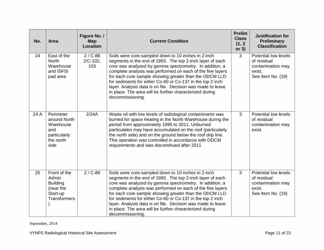
September, 2014
VYNPS Radiological Historical Site Assessment Page 11 of 23
No. AreaFigure No. /
MapLocation
Current ConditionPrelimClass(1, 2or 3)
Justification forPreliminary
Classification
24 East of theNorthWarehouseand ISFSIpad area
2 / C-882/C-102,
103
Soils were core-sampled down to 10 inches in 2-inchsegments in the end of 1993. The top 2-inch layer of eachcore was analyzed by gamma spectrometry. In addition, acomplete analysis was performed on each of the five layersfor each core sample showing greater than the ODCM LLDfor sediments for either Co-60 or Cs-137 in the top 2 inchlayer. Analysis data is on file. Decision was made to leavein place. The area will be further characterized duringdecommissioning.
3 Potential low levelsof residualcontamination mayexist.See Item No. (19)
24 A Perimeteraround NorthWarehouseandparticularlythe northside
2/24A Waste oil with low levels of radiological contaminants wasburned for space heating in the North Warehouse during theperiod from approximately 1995 to 2011. Unburnedparticulates may have accumulated on the roof (particularlythe north side) and on the ground below the roof drip line.This operation was controlled in accordance with ODCMrequirements and was discontinued after 2011
3 Potential low levelsof residualcontamination mayexist.
25 Front of theAdminBuilding(near theStart-upTransformers)
2 / C-89 Soils were core-sampled down to 10 inches in 2-inchsegments in the end of 1993. The top 2-inch layer of eachcore was analyzed by gamma spectrometry. In addition, acomplete analysis was performed on each of the five layersfor each core sample showing greater than the ODCM LLDfor sediments for either Co-60 or Cs-137 in the top 2 inchlayer. Analysis data is on file. Decision was made to leavein place. The area will be further characterized duringdecommissioning.
3 Potential low levelsof residualcontamination mayexist.See Item No. (19)

September, 2014
VYNPS Radiological Historical Site Assessment Page 12 of 23
No. AreaFigure No. /
MapLocation
Current ConditionPrelimClass(1, 2or 3)
Justification forPreliminary
Classification
26 Front of theAdministration Building(along thesidewalk)
2 / C-91 Soils were core-sampled down to 10 inches in 2-inchsegments in the end of 1993. The top 2-inch layer of eachcore was analyzed by gamma spectrometry. In addition, acomplete analysis was performed on each of the five layersfor each core sample showing greater than the ODCM LLDfor sediments for either Co-60 or Cs-137 in the top 2 inchlayer. Analysis data is on file. Decision was made to leavein place. The area will be further characterized duringdecommissioning.
3 Potential low levelsof residualcontamination mayexist.See Item No. (19)
27 NorthwestCorner of theProtectedArea
2 / C-90 Soils were core-sampled down to 10 inches in 2-inchsegments in the end of 1993. The top 2-inch layer of eachcore was analyzed by gamma spectrometry. In addition, acomplete analysis was performed on each of the five layersfor each core sample showing greater than the ODCM LLDfor sediments for either Co-60 or Cs-137 in the top 2 inchlayer. Analysis data is on file. Decision was made to leavein place. The area will be further characterized duringdecommissioning.
3 Potential low levelsof residualcontamination mayexist.See Item No. (19)
Buildings and Structures Inside the Protected Area
28 ReactorBuilding andDrywell
1 / A4 andA5, & B4and B5
The Reactor Building and Drywell house the reactor and allof the supporting pumps, pipes and demineralizersassociated with the operation of a nuclear reactor. TheSpent Fuel Pool is also located in the Reactor Building. Thepiping, coolers and pumps required to support the SpentFuel Pool are also located in the Reactor building. Most ofthe radioactive material at the station is located in theDrywell and Reactor Building.
1 Potential forsignificant levels ofcontamination.

September, 2014
VYNPS Radiological Historical Site Assessment Page 13 of 23
No. AreaFigure No. /
MapLocation
Current ConditionPrelimClass(1, 2or 3)
Justification forPreliminary
Classification
29 RadioactiveWasteBuilding
1 / A4 andB4
The Radioactive Waste Building houses the tanks, pipingand filters required for processing radioactive water at thefacility. It also houses the filters for maintaining the SpentFuel Pool water chemistry. The amount of radioactivematerial in the building is significant.
1 Potential forsignificant levels ofcontamination.
30 Radwastetanks, Moat,trench, sumpandassociatedpiping
1 / A4 These tanks are used on a regular basis to processcontaminated water that is returned to the facility duringplant operation. Rain water that collects in the moat andsump is pumped to the Radioactive Waste building to beprocessed with contaminated plant water. The moat area isroutinely surveyed for contamination by the plant staff andno contamination has been detected.
1 Potential forcontamination in thetanks to exceedDCGLs.
31 TurbineBuilding (TB)
1 / B4 andB5
The Turbine Building is the largest building on site andextends from the Service Building at the north end to theback of the Maintenance Shop at the south end. Thebuilding contains the main turbine and the pumps,demineralizers and associated piping required to operatethe turbine. The liquids and gases moving through thesesystems will leave the systems moderately contaminatedafter the plant is shut down.
1 Potential forcontamination toexceed DCGLs.
32 TurbineBuilding (TB)Basement
1 / B4 andB5
The Turbine Building Basement is the area in the TB thatreceives all drainage from the steam, feed and condensatesystems. These systems are only slightly contaminated.The TB clean sump identified in Item No. 37 is in thesouthern end of this basement.
1 Potential forcontamination toexceed DCGLs.
33 ContainmentAccessBuilding(CAB)
1 / A5 The Containment Access Building is a very large buildingwhich is used to provide shelter for moving equipment andmaterial in and out of the Reactor Building. Radioactivematerial stored in the building is sealed so as to prevent thespread of contamination. Occasionally, large quantities ofradioactive material, including new and spent fuelassemblies, are moved through this building.
1 Potential forcontamination toexceed DCGLs.

September, 2014
VYNPS Radiological Historical Site Assessment Page 14 of 23
No. AreaFigure No. /
MapLocation
Current ConditionPrelimClass(1, 2or 3)
Justification forPreliminary
Classification
34 AdvancedOff-Gas(AOG)Building
1 / A5 andB5
The Advanced Off-Gas Building contains the recombiners, adryer skid, two guard bed charcoal filters, the main hold-upcharcoal filters and all of the associated piping. When theplant is shut down, there will be very little residualradioactive material left in the system, except for thecharcoal beds. Once the charcoal is removed, there shouldbe only trace amounts of radioactive material remaining.
1 Potential forcontamination toexceed DCGLs.
35 CondensateStorageTank (CST)
2 / C-104 In 1976, 83,000 gallons of CST water was released to theConnecticut River from an overflow pipe over a 2-day periodvia electrical conduit from the Condensate Storage TankMoat, which eventually flowed to the South Storm DrainSystem. This was documented in NRC Report No: RO-76-22/1T. In addition, in 1986 a leak was discovered in thebottom of the tank that had saturated the sand layerbetween the tank bottom and the underlying concretesupport structure. Telltale drains are embedded within thesand layer. The leak was evidenced by water from thetelltale drains in the CST ante-room. The bottom of the tankwas replaced with new aluminum plates and the leak wascurtailed. All of the leakage from the tank was returned tothe Radwaste Building via the floor drains in the CST Moatarea.
1 Potential forcontamination toexceed DCGLs.
36 CST Building 1 / B5 The CST Building is a portion of the CST Moat that isenclosed and has a roof to shelter some of theinstrumentation and electrical equipment associated withthe operation of the CST. See Item No. 35 for additionalinformation relating to the tank overflow that occurred in1976 and the tank leak in 1986.
1 Potential forcontamination toexceed DCGLs.

September, 2014
VYNPS Radiological Historical Site Assessment Page 15 of 23
No. AreaFigure No. /
MapLocation
Current ConditionPrelimClass(1, 2or 3)
Justification forPreliminary
Classification
37 TurbineBuildingClean Sump
2 / C-100 The sump was contaminated by the overflow of theCondensate Demineralizer Backwash Receiving Tank on8/14/92. The overflow resulted in release of a small amountof radioactive contamination to the Service Water Systemand thence to the Connecticut River. This sump has beenprotected with a berm so that this incident cannot berepeated. Operation procedures were enhanced to reducethe possibility of an overflow of the CondensateDemineralizer Backwash Receiving Tank. Very smallamounts of Co-60 were identified in the sump water inMarch of 1999. As a result, the procedure for monitoringthis water has been enhanced to include a more frequentisotopic analysis. Results are reported in the AnnualEnvironmental Radiological Operating Report. The releaseswere assessed for dose consequence. Reports were madeto the State of Vermont and the NRC.
2 The potential forresidualcontaminationexists.
38 MaintenanceMachineShop
1 / B5 Tools and small items with limited fixed radioactive materialare stored here. On occasion a temporary RCA /containment area was set up in the shop to work oncontaminated components. When these jobs werecompleted, the containment area was decontaminated.There is the potential that trace levels of contamination mayhave accumulated in this shop.
2 The potential forresidualcontaminationexists.
39 NorthWarehouse
1 / B4 This building is a RCRA hazardous waste storage area andhas been used to store containers of radioactive wasteawaiting shipment. The building has a concrete slab floorwith an approximately six-inch high berm around theperimeter of the building. Current plans call for this buildingto be removed to allow construction of an addition to theISFSI pad. In 1995 a drum of mixed waste in the buildingwas found to be leaking. The drum was overpacked, andthe area of the spill was cleaned up. Floor drains that used
2 The potential forresidualcontaminationexists.

September, 2014
VYNPS Radiological Historical Site Assessment Page 16 of 23
No. AreaFigure No. /
MapLocation
Current ConditionPrelimClass(1, 2or 3)
Justification forPreliminary
Classification
to go to Radwaste are now plugged with concrete.
40 ServiceBuilding andoffices (Notincluding theHP checkpoint andChemistrylab; see ItemNo. 8 above)
1 / B4 This building is on the north end of the Turbine Building andcontains the Chemistry Laboratory, DecontaminationShowers and the Health Physics (HP) check point. The labdrain identified in Item No. 8 above is located in the lowerlevel of this building. The remainder of the building containsprimarily offices. The check point is the entry way into theRCA. The lab and decontamination showers are inside theRCA.
2 There is thepotential that verylow levels ofcontaminationbelow what can bedetected in theportal monitors atthe RCA exits mayhave been trackedinto the building byworkers leaving theRCA andaccumulated overtime.
41 ControlBuilding
1 / B4 This building contains the Control Room, the Cable Vaultand the Switchgear rooms. Radioactive material was notused or stored in this building, but because of its proximityto the power block there is the potential that trace levels ofcontamination may have accumulated in this building.
3 The potential foraccumulation of lowlevels ofcontaminationexists.

September, 2014
VYNPS Radiological Historical Site Assessment Page 17 of 23
No. AreaFigure No. /
MapLocation
Current ConditionPrelimClass(1, 2or 3)
Justification forPreliminary
Classification
42 AdminBuilding
1 / B4 The Administration Building is on the north end of theTurbine Building and consists primarily of offices.Radioactive material was not used or stored in this building,but because of its proximity to the power block there is thepotential that trace levels of contamination may haveaccumulated in this building.
3 Potential low levelsof residualcontamination mayexist.
43 John DeereDieselBuilding
1 / B4 This building is on the north end of the Protected Area.Radioactive material was not used or stored in this building,but because of its proximity to the power block there is thepotential that trace levels of contamination may haveaccumulated in it. Currently this building is scheduled to beremoved to allow expansion of the ISFSI dry fuel storagearea.
3 Potential low levelsof residualcontamination mayexist.
44 ConstructionOfficeBuilding(COB)
1 / A5 The Construction Office Building is on the east side of theTurbine Building and consists primarily of offices.Radioactive material was not used or stored in this building,but because of its proximity to the power block there is thepotential that trace levels of contamination may haveaccumulated in this building.
3 Potential low levelsof residualcontamination mayexist.
45 Clean WorkShop /ConstructionStorageBuilding
1 / A5 The Clean Work Shop is on the southeast corner of theProtected Area and consists primarily of a storage area andlocker room. Radioactive material was not used or stored inthis building, but because of its proximity to the power blockthere is the potential that trace levels of contamination mayhave accumulated in this building.
3 Potential low levelsof residualcontamination mayexist.
46 SouthWarehouse
1 / B5 The South Warehouse is on the south end of the ProtectedArea and consists primarily of a storage area for virgin andused oils and office space. Radioactive material was notused or stored in this building, but because of its proximityto the power block there is the potential that trace levels ofcontamination may have accumulated in this building.
3 Potential low levelsof residualcontamination mayexist.

September, 2014
VYNPS Radiological Historical Site Assessment Page 18 of 23
No. AreaFigure No. /
MapLocation
Current ConditionPrelimClass(1, 2or 3)
Justification forPreliminary
Classification
47 Tan Building 1 / B5 The Tan Building is a temporary building on the southwestcorner of the Protected Area and consists primarily of astorage area and office space. Radioactive material wasnot used or stored in this building, but because of itsproximity to the power block there is the potential that tracelevels of contamination may have accumulated in thisbuilding.
3 Potential low levelsof residualcontamination mayexist.
48 Hydrogen /CO2 PurgeBuilding
1 / B5 The Hydrogen / CO2 Purge Building is located on the westside of the Turbine Building and just south of the roll updoor. Radioactive material was not used or stored in thisfacility, but because of its proximity to the power block thereis the potential that trace levels of contamination may haveaccumulated in this building.
3 Potential low levelsof residualcontamination mayexist.
49 IntakeStructure
1 / A4 The Intake Structure is located in the northeast corner of theProtected Area. Radioactive material was not used or storedin this structure but because of its proximity to the powerblock there is the potential that trace levels of contaminationmay have accumulated in this building. Trace amounts ofradioactivity have been detected in the river silt that may befound in the underwater portions of this structure.
3 Potential low levelsof residualcontamination mayexist.
50 ChemicalAdditionBuilding
1 / A4 The Chemical Addition Building is located at the south endof the Intake Structure, near the Connecticut River.Radioactive material was not used or stored in this buildingbut because of its proximity to the power block there is thepotential that trace levels of contamination may haveaccumulated in this building.
3 Potential low levelsof residualcontamination mayexist.
51 NitrogenStorageFacility
1 / A4 The Nitrogen Storage Facility is a tank complex located onthe east side of the Reactor Building, between the buildingand the Connecticut River. Radioactive material was notused or stored in this facility and the potential for anycontamination is very low.
3 Potential low levelsof residualcontamination mayexist.

September, 2014
VYNPS Radiological Historical Site Assessment Page 19 of 23
No. AreaFigure No. /
MapLocation
Current ConditionPrelimClass(1, 2or 3)
Justification forPreliminary
Classification
52 BottleStorageShed - Northof ControlBuilding
1 / B4 The Bottle Shed is used to store gas bottles. Radioactivematerial was not used or stored in this shed but because ofits proximity to the power block there is the potential thattrace levels of contamination may have accumulated in thisbuilding.
3 Potential low levelsof residualcontamination mayexist.
53 Large MixedGases Shedeast of SouthWarehouse
1 / A5 This shed is used to store gas bottles. Radioactive materialwas not used or stored in this shed but because of itsproximity to the power block there is the potential that tracelevels of contamination may have accumulated in thisbuilding.
3 Potential low levelsof residualcontamination mayexist.
54 PropaneStorageShed
1 / B5 This shed was used to store propane gas bottles for forklifts.Radioactive material was not used or stored in this shed butbecause of its proximity to the power block there is thepotential that trace levels of contamination may haveaccumulated in this building.
3 Potential low levelsof residualcontamination mayexist.
55 NewWarehouse
1 / B5 For many years this facility performed the function of aShipping and Receiving facility. During these times, someradioactive material was shipped and received in this area.There is a small storage area for Special Nuclear Material inthe New Warehouse. There is the potential that trace levelsof contamination may have accumulated in this area.
3 Potential low levelsof residualcontamination mayexist.
56 Sumps (allexcept Item#s: 13, 30and 37)
1 / A4 to A5and B4 toB5
Sumps in the plant will be characterized and remediated, ifnecessary, at the time of decommissioning.
** **To be determined.
Buildings and Structures Outside the Protected Area

September, 2014
VYNPS Radiological Historical Site Assessment Page 20 of 23
No. AreaFigure No. /
MapLocation
Current ConditionPrelimClass(1, 2or 3)
Justification forPreliminary
Classification
57 Plant Stack 1 / B3 Heating and ventilating exhaust from the major plantbuildings is discharged through the Plant Stack. Inaddition, the Off Gas system, the Standby Gas TreatmentSystem and the Gland Seal Exhauster discharge throughthe Plant Stack. The Plant Stack sump was addressed inItem No. 13 above. There is the potential thatcontamination from the air discharged through the stackmay have plated out and could result in measurable activity.
2 The potential foraccumulation of lowlevels ofcontaminationexists.
58 West CoolingTower
3 / B-1 In 1993, low levels of contamination were found in the siltremoved from the deep basin under the West CoolingTower. The source of the silt is cooling water withdrawnfrom the Connecticut River. The first silt volume removedwas 14,000 cu. ft. Every 18 months, the Deep Basin isinspected and if necessary, additional silt is removed. It isestimated that each time the volume removed will be anadditional 4,000 cu. ft. VYNPS submitted an amendment tothe 10 CFR 20.2002 application for spreading of septicsludge, to also allow spreading of the cooling tower silt onthe same 2-acre South Field Application Area where theseptic sludge is spread. That amended application wasapproved by the NRC on 6/18/97. The application andapproval are in Appendix F of the ODCM. The silt issampled, analyzed, spread and monitored in accordancewith VYNPS approved procedures, and is spread in theSouth Field Application Area only if the measured activity isgreater than background level. The silt collected as of June1997 was spread in the fall of 1998, and was last spread onOctober 19, 2009.
3 Potential low levelsof residualcontamination mayexist in the silt.

September, 2014
VYNPS Radiological Historical Site Assessment Page 21 of 23
No. AreaFigure No. /
MapLocation
Current ConditionPrelimClass(1, 2or 3)
Justification forPreliminary
Classification
59 East CoolingTower
1 / B6 andB7
Because river water passes through both the East and WestCooling Towers, there is the potential that low levels ofcontamination that has been found in silt accumulated in theDeep Basin of the West Cooling Tower also may be foundin the shallow basin beneath the East Cooling Tower andthe systems associated with this tower. See Item No. (58).
3 Potential low levelsof residualcontamination mayexist in the silt.
60 AreaBetweenCoolingTowers
3 / B-2 This area had been used for temporarily storing silt removedfrom the Deep Basin of the West Cooling Tower and soilexcavated during modification of the Protected Area until itwas spread in the South Field Application Area under anamendment to the 10 CFR 20.2002 Exemption Request,which was approved in 1997. A pathway assessment for thetemporary placement of the material was completed. Thetemporarily stored material was removed in December2004. The area has been sampled and characterized andfound to contain no plant related radionuclides.
3 Potential low levelsof residualcontamination mayexist in the silt.
61 Spray Pond 1 / B6 The Spray Pond is located south of the Protected Area,north of the Cooling Towers. Since December 2004, siltremoved from the West Cooling Tower Deep Basin thatcontains trace amounts of radioactivity is temporarily storedin the spray pond before being spread in the South FieldApplication Area.
3 Potential low levelsof residualcontamination mayexist in the silt.
62 DischargeStructure
1 / A6 The Discharge Structure is located immediately south of theProtected Area adjacent to the Connecticut River.Radioactive material was not used or stored in the structure,but has been measured in the South Storm Drain Systemthat empties into the Discharge Structure and in the river siltcollected from the cooling towers.
3 Potential low levelsof residualcontamination mayexist.

September, 2014
VYNPS Radiological Historical Site Assessment Page 22 of 23
No. AreaFigure No. /
MapLocation
Current ConditionPrelimClass(1, 2or 3)
Justification forPreliminary
Classification
63 Area innorthernportion ofOwnerControlledArea
3 / B-5 Sampling was conducted in 1999/2001 with one sampleindicating low levels of Co-60. Containers of contaminatedasbestos were identified in this area in 1984 and was likelyremoved during the asbestos control program conductedduring the mid-1980s. This area was also a former snow laydown area. Much of the area was used for construction ofthe new VELCO substation in 2009. Soil samples of thearea collected for construction of the VELCO substationwere all non-detectable for plant-related radionuclides.
3 Potential low levelsof residualcontamination mayexist.
64 Former BurnArea
3 / B-6 VY burned waste wood scraps in this area during the late1970s. Sampling was completed in 2001 and a monitoringwell was installed. The area was also sampled duringconstruction of the new VELCO substation and adjacentparking lot. Sample results from 2009 were non-detectable.
3 Potential low levelsof residualcontamination mayexist.
65 Low-Levelradioactivewastestorage padnorth of theNorthWarehouse
1 / B3 to A4 This pad was used to store containers with radioactivematerial awaiting shipment and Sealand containerscontaining equipment.
2 The potential forresidualcontaminationexists.
66 TurbineRotorBuildings
1 / C3 The Turbine Rotor Buildings are 4 large temporary buildingson the west border of the Protected Area. These buildingshouse the original turbine rotors and casings that werereplaced in 1995. There should be only trace amounts ofradioactive material on this equipment.
3 Potential low levelsof residualcontamination mayexist.

September, 2014
VYNPS Radiological Historical Site Assessment Page 23 of 23
No. AreaFigure No. /
MapLocation
Current ConditionPrelimClass(1, 2or 3)
Justification forPreliminary
Classification
67 Haz MatStorageBuilding(next toMaintenanceStorageBuilding)
1 / B4 This building is used to store Hazardous Waste and mayhave stored Mixed Hazardous Waste (waste that is bothhazardous and radioactive). Radioactive material was notnormally stored or used in this building but there is thepotential that trace levels of radioactive contamination mayhave accumulated in this building.
3 Potential low levelsof residualcontamination mayexist.
68 Shipping andReceivingBuilding
1 / C7 This building is used for shipping and receiving materialfrom VYNPS. At times, radioactive material has beenshipped from or received at this facility. Radioactivematerial was not normally stored or used in this building butthere is the potential that trace levels of radioactivecontamination may have accumulated in this building.
3 Potential low levelsof residualcontamination mayexist.
69 Gate House1
1 / C7 This is the main entrance and security checkpoint forVYNPS. Radioactive material was not used or stored in thisbuilding but there is the potential that trace levels ofcontamination may have accumulated in this building.
3 Potential low levelsof residualcontamination mayexist.
70 Gate House2
1 / B4 Radioactive material was not used or stored in this buildingbut there is the potential that trace levels of contaminationmay have accumulated in this building.
3 Potential low levelsof residualcontamination mayexist.
71 Gate House3
1 / A5 andA6 & B5and B6
Radioactive material was not used or stored in this buildingbut there is the potential that trace levels of contaminationmay have accumulated in this building.
3 Potential low levelsof residualcontamination mayexist.
72 Empty DrumStorageBuilding
1 / B2 Radioactive material was not used or stored in this buildingbut there is the potential that trace levels of contaminationmay have accumulated in this building.
3 Potential low levelsof residualcontamination mayexist.

September, 2014
VYNPS Radiological Historical Site Assessment Page 1 of 4
Table 2 Preliminary Classification of the Radiological Status of Plant Buildings, Structures and Site Soil
Impacted Non-ImpactedFigure/Location Class 1 Figure/
Location Class 2 Figure/Location Class 3 Figure/
Location
Fig 1 /A4, A5 &B4, B5
Reactor Building(RB) Fig 1 / B5 Maintenance Machine
Shop Fig 1 / B4 Control Building Fig 1 / B2 Dog House Building
Fig 1 /B4
Service Building(RCA) Fig 1 / B4 North Warehouse Fig 1 / A4 Nitrogen Storage
FacilityFig 1 / B7,B8
Hydrogen StorageFacility
Fig 1 /B4, B5
Turbine Building (TB)Including thebasement
Fig 1 / B3 Plant Stack Fig 1 / B5 South Warehouse Fig 1 / C2 Met Tower - North
Fig 1 /A4, B4
Radioactive WasteBuilding (RWB)
Fig 1 A5to B3
HVAC duct from Plantbuildings to the PlantStack
Fig 1 / B5 New Warehouse Fig 1 / C5 Met Tower - South
Fig 1 /B5
Condensate StorageTank and associatedstructure (CST)
Fig 2 /C-102, C-103
Soil adjacent to theNorth Warehouse (eastand west)
Fig 1 / A5 Construction OfficeBuilding (COB) Fig 1 / C3 Salt Storage Shed
Fig 1 /A5
Containment AccessBuilding (CAB)
Fig 2 /C-87
Surface soil East ofCask Loading Bay Fig 1 / B4
Bottle Storage Shed -North of ControlBuilding
Fig 1 / B3 SOCA Building - North
Fig 1 /A5, B5
Advanced Off-GasBuilding (AOG)
Fig 2 /C-102 andC-103
Surface soil in thevicinity of manhole MH-11E on the gravel areabetween the NorthWarehouse and theblack top roadway(closer to the roadway
Fig 1 / B6,B7 Cooling Tower 1 Fig 1 / C4 SOCA Building - West
Fig 1 /B5
Soil nearunderground pipechase located westof AOG Drain Pit
Fig 3 /B-1
Surface soil in the 2-acre South FieldApplication Area.
Fig 1 / B6,B7 Cooling Tower 2 Fig 1 / B3 Sally Port - North
Fig 2 /A-6
Soil underneathChemistry Lab
Fig 1 / B3,B4
Low-Level RadwasteStorage Pad Fig 1 / A6 Discharge Structure Fig 1 / C6 Sally Port - South

September, 2014
VYNPS Radiological Historical Site Assessment Page 2 of 4
Impacted Non-ImpactedFigure/Location Class 1 Figure/
Location Class 2 Figure/Location Class 3 Figure/
Location
Fig 2 /A-5
Surface soil nearestthe cask room doorson the northeast sideof the RadwasteBuilding
Fig 3 / B-1 Septic System Sludge Fig 1 / A4 Intake Structure Fig 1 / B3 Domed Building(Maine Yankee Bldg.)
Fig 2 /C-104
Soil underCondensate StorageTank and associatedstructure (CST)
Fig 2 / C-101 HHB Room Main Line Fig 1 / B5 Propane Storage Shed
(for forklifts) Fig 1 / C4 Power Uprate Building(PUB)
Fig 2 /A-1
North Storm DrainSystem
Fig 2 /A-2 / A-3
North Storm DrainOutfall & River
SedimentFig 1 / B5 Tan Building (office
space) Fig 1 / B5 Station Black-OutDiesel Building
Fig 2 /A-4 South Storm Drain
SystemFig 2 /C-
102 Sandblast Grit Area Fig 1 / B5 Hydrogen / CO2 PurgeBuilding Fig 1 / C4 Plant Support Building
(PSB)
Fig 2 / A-4 Manhole 12 Fig 1 / B4 Service Building Offices Fig 1 / B2 Empty Drum Storage
BuildingFig 2 /
A-5Northeast Side of
Radwaste BuildingFig 2 / C-100
Turbine Building CleanSump Fig 1 / C7 Gate House 1
Fig 1 / A-4
Radwaste Tanks,Moat, etc. Fig 2/24A North Warehouse
waste oil burn fallout Fig 1 / B4 Gate House 2
Fig 1 / A5,A6 & B5,B6
Gate House 3
Fig 1 / A5 Clean Work Shop
Fig 1 / B6 Spray Pond
Fig 1 / A5Large mixed gasesShed - (east of SouthWarehouse)
Fig 1 / A4 Chemical AdditionBuilding

September, 2014
VYNPS Radiological Historical Site Assessment Page 3 of 4
Impacted Non-ImpactedFigure/Location Class 1 Figure/
Location Class 2 Figure/Location Class 3 Figure/
Location
Fig 1 / B4 Admin Building - (Northof Turbine Building)
Fig 1 / B3to A4
Stack Sump dischargeline from Stack to theRadwaste Building
Fig 1 / A5to B3
Underground gaseouseffluent lines from theplant to the Stack
Fig 1 / C3 Turbine Rotor StorageBuildings (4)
Fig 1 / B3 Haz Mat StorageBuilding
Fig 1 / B4 John Deere DieselBuilding
Fig 1 / C7 Shipping andReceiving
Fig 3 /B-2
Surface soil in the areabetween the CoolingTowers
Fig 3 /B-6
Surface soil in theformer wood burningarea in the northparking lot
Fig 1 / B6 Surface soil in theSpray Pond area
Fig 3 /B-1
Silt removed from thedeep basin under theWest Cooling Tower
Fig 3 / B-3 Septic Leach Fields &Tanks

September, 2014
VYNPS Radiological Historical Site Assessment Page 4 of 4
Impacted Non-ImpactedFigure/Location Class 1 Figure/
Location Class 2 Figure/Location Class 3 Figure/
Location
Fig 3 / B-4 Interior Off-Gas Filters
9 AreasOutside GroundSurfaces in ProtectedArea

September, 2014
VYNPS Radiological Historical Site Assessment Page 1 of 1
Figure 1 Preliminary Classification of the Radiological Status of Plant Buildings and Structures

September, 2014
VYNPS Radiological Historical Site Assessment Page 1 of 1
Figure 2 Map “A” Showing Areas of Radiological Conditions of Interest

September, 2014
VYNPS Radiological Historical Site Assessment Page 1 of 1
Figure 3 Map “B” Showing Areas of Radiological Conditions of Interest