versa link atx-250 manual - fax switchfaxswitch.com/bear/faxswitch/info/atx250_manual.pdfi atdt 1...
TRANSCRIPT

Versa-LinkTM
ATX-250
Online OperatingInstructions
www.multi-link.infowww.faxswitch.com
www.multi-link.net
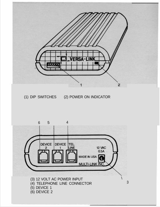
(1) DIP SWITCHES (2) POWER ON INDICATOR
6 5 4
(3) 12 VOLT AC POWER INPUT \(4) TELEPHONE LINE CONNECTOR(5) DEVICE 1(6) DEVICE 2
3

ATX-250OPERATING MANUAL
1.
2 .
3 .
4 .
5 .
6 .
TABLE OF CONTENTS Page
INTRODUCTIONN . . . . . . . . . . . . . . . . . . . . . . . . . . . . . . . . . . . . . . . . . . . . . . . 2Basic Features / Call Processing
E Q U I P M E N T . . . . . . . . . . . . . . . . . . . . . . . . . . . . . . . . . . . . . . . . . . . . . . . . . . . . . . . . 4FAX Machines / MODEMS / Telephones and multi-line systems / Other equipment
A P P L I C A T I O N S . . . . . . . . . . . . . . . . . . . . . . . . . . . . . . . . . . . . . . . . . . . . . . . . 7Adding FAX or MODEM to a voice line / Expanding a FAX line / Allowing two datadevices to share one line
O P E R A T I O N . . . . . . . . . . . . . . . . . . . . . . . . . . . . . . . . . . . . . . . . . . . . . . . . . . . . . . . . 9Outbound calls // Manual transfer // Automatic FAX transfer / CALL OPTI-MIZER
I N S T A L L A T I O N . . . . . . . . . . . . . . . . . . . . . . . . . . . . . . . . . . . . . . . . . . . . . . . . . 1 4Your phone line / Telephone systems / Multi-line phones // Attaching FAX anddata devices
USER SELECTABLE FEATURES . . . . . . . . . . . . . 19Configuration switches / Device selection codes / Factory settings
C O M M O N L Y A S K E D Q U E S T I O N S ............... 2 2G L O S S A R Y ............................................................ 23
APPENDICES
A. TECHNICAL SPECIFICATIONS . . . . . . . . . . . . . . . . 26
B. FCC, WARRANTYA N D S E R V I C E I N F O R M A T I O N . . . . . . . . . . . . . . . . . 27
VERSA-LINK ATX-250

INTRODUCTION TO THE WORLD OFCALL PROCESSING
answering machines, WATS lines, phone mail systems,credit approval systems, and loop start TELEX equipment.
Versa-Link allows you to expand your presentcommunications network without installing an expensivededicated phone line for each device. Versa-Link providesfor greater utilization of phone lines and office equipment.
1 . 1 B A S I C F E A T U R E S
Versa-Link is a 24-hour communications control centerthat automatically analyzes and routes incoming calls tothe proper equipment. Your Versa-Link ATX-250permits a caller to remotely access your telephone, FAXmachine, computer MODEM, or other equipment youmay have attached. Standard features include: - AutoFAX Detection - CALL OPTI-MIZER - AutomaticRing-through to your most-used equipment -Manual Transfer - Calling Party Hang Up Detect.
CALL OPTI-MIZER is a unique feature that makes yourphone line look more like a dedicated voice line to voicecallers, and more like a dedicated data line to FAX orcomputer MODEM callers.Calls can be manually transferred at any time by either thecaller or the called party.Versa-Link’s data protection feature allows you to transmitFAX or computer MODEM data without the fear ofsomeone disturbing the transmission by picking up anextension phone. It also gives you peace of mind knowingthat your voice call will never be interrupted by a FAX orMODEM.
Your Versa-Link ATX-250 is a powerful Computerized CallProcessor that allows more than one telephone device toshare a single phone line. Versa-Link is compatible with /standard telecommunication and off ice equipmentincluding: Facsimile (FAX) machines, computer MODEMS, -PC FAX Boards, single and multi-line telephone systems, /
VERSA-LINK ATX-250
2

INTRODUCTION
Another unique feature is Versa-Links surge suppressorwhich provides added protection from lightning strikes avoltage surges that could damage your sensitivecommunications equipment.
1 . 2 C A L L P R O C E S S I N GCall processing is the task of routing telephone voice anddata calls to one of several destinations. Your phonecompany can be considered a very large call processor.
To better understand the principles behind call processing,consider the following example:
l A receptionist who answers all incoming calls(in this case, the Versa-Link ATX-250)
l A Customer Service Agent.l A sales agent.
When a phone call comes in, the Versa-Link acts as areceptionist and answers the call. If the caller requests thesales agent by dialing an access code, the Versa-Link willtransfer the call without disturbing anyone else. If no codeis dialed, the call is automatically directed to the customerservice agent for information and further routing. Thecustomer service agent may re-direct calls to the salesagent by entering the proper access code.
Your ATX-250 can be used to process calls to your voiceand data equipment, just as it did in the above example. Ifyou are adding FAX or a computer MODEM to a voice line,you have:l A Versa-Link ATX-250 that answers all calls
and transfers them to the proper device.l A telephone system that handles most calls.l A FAX machine or a computer MODEM.
This is just one application. As you will see, your Versa-Link is not just a switch. It’s a very smart call processorthat does exactly what it’s told to do, and does it very well.
VERSA-LINK ATX-250
3

EQUIPMENT
Your ATX-250 has special features that work extremelywell with FAX machines and PC FAX Boards. The AutoFAX Detection feature allows most FAX calls to transfer toyour FAX machine automatically.
The vast majority of FAX machines sold today have theability to dial the number of the receiving FAX frommemory, and then identify itself as a FAX machine with atone (called CNG tone or AUTO-FAX tone). It will thencontinue to identify itself until the called FAX answers thecall. When an ATX-250 is used at the receiving end, it candetect this FAX identification tone, and automaticallytransfer the call to the FAX machine on the receiving end,without ringing the telephone.
Occasionally, calls will come from a FAX machine withouta FAX identification tone. This may happen if the callingperson is using an older FAX machine, or dials the numbermanually using the FAX handset. In most applications,calls without this auto-FAX tone will be routed to yourtelephone system. The call can be manually transferred tothe FAX machine by dialing *2 (or another selectedcode) on your telephone keypad. Either the caller or theperson who answers can transfer the call. See section4.2.2 for details of operation.
If possible, ask people who send you FAX messages toprogram your number into their FAX machine’s memory.This will allow FAX calls to always be processedautomatically.
Your Versa-Link ATX-250 is compatible with virtually allmodern telecommunications equipment, including singleand multi-line telephones. Because your ATX-250 isinstalled between your telephone system and the phonecompany, it can direct all your telephone traffic to theproper equipment. The most popular types of equipmentused with a Versa-Link ATX-250 are described below.
2 . 1 F A X M A C H I N E S
VERSA-LINK ATX-250
4

EQUIPMENT
2 . 2 C O M P U T E R M O D E M SYour ATX-250 is compatible with all dial-up MODEM S.Usually, MODEMS are attached to the DEVICE 2connector of your ATX-250. Your ATX-250 will transferincoming calls to your MODEM when the calling MODEMdials *2 (or another code, if re-programmed) after thecall has been answered by your Versa-Link. The dataprotection feature prevents interruptions from othertelephone equipment.
If your MODEM is only used for out-bound communication,you do not need to be concerned with the deviceselection code for the MODEM.The device selection code for your MODEM is best dialedby the calling MODEM. For example, when calling into aMODEM attached to DEVICE 2, with the ATX-250 factoryprogramming, the dialing command for a Hayescompatible MODEM would be:
I ATDT 1 203 555 1234 ,,,,*2 I
The commas will generate pauses in the dialing MODEM.The number of pauses may need to be changed to allowenough time’for the call to be switched through thetelephone company, particularly if the calling MODEM isdialing long-distance.
The selectable device codes can be reconfigured to addsecurity to any system. Your ATX--250 will restrict accessto only those callers who dial the right device selectioncode. See section 6, USER SELECTABLE FEATURES, tochange this code.
Some MODEMS cannot dial the * symbol. Therefore, ifyou plan to connect a computer MODEM, it is best tochoose a device selection code for your computer thatdoes not use the * symbol.
VERSA-LINK ATX-250
5

OPERATION
Your ATX-250 will route incoming calls to the properequipment and prevent other devices from interfering withthe ongoing communication.
4 . 1 O U T B O U N D C A L L SYour ATX-250 will only allow one DEVICE port to accessthe telephone line at a time. For example, if you aresending or receiving a FAX, your telephones andextensions will be unable to interrupt the communication. Ifyou pick up your phone or FAX and hear a busy signal,then another device is already using the line.
4 . 2 I N C O M I N G C A L L SIncoming calls can be routed to your communicationsequipment in several ways:
- Calls may be automatically transferred to your FAXmachine if the caller is a FAX that produces a FAXidentification tone.
- Calls may be manually transferred by dialing touchtones from either end of the line or with pulse-dialingtelephone equipment attached directly to your Versa-Link ATX-250. Tones may be entered by the callingparty any time after the first ring.
- Calls can be transferred to your MODEM if the caller isan auto-dial MODEM that dials the proper deviceselection code.
- All calls may be automatically transferred to DEVICE 2after hours if CALL OPTI-MIZER is activated.
VERSA-LINK ATX-250
9

EQUIPMENT
2.3 TELEPHONES AND MULTI -L INES Y S T E M S
Your ATX-250 may be used with single and multi-linetelephone equipment. Both tone-dialing and pulse-dialingequipment may be used with your ATX-250. See section4.2.2 for restrictions when using pulse-dialing equipment.
I I IP
KSU orI
PBX
2 . 4 O T H E R E Q U I P M E N TYour ATX-250 is also compatible with Credit AuthorizationTerminals, Electronic Mail Terminals, and Loop-Start dial-up TELEX machines.
Your ATX-250 can also be used with answering machinesand cordless phones.
2 . 5 “CALLER ID” SERVICECOMPATIBIL ITY
Your ATX-250 is now programmed to wait for and detect thetransmission of “Caller ID” data. This function allows the callingparty’s phone number to appear on your “Caller ID” display unitbefore your ATX-250 routes the call to any device.
VERSA-LINK ATX-250
6

APPLICATIONS
There are many applications for your Versa-Link ATX-250.One unique advantage that Versa-Link gives you is theability to change its operation as your business grows andyour telephone needs change.
A few of the popular applications are described here.
3 . 1 A D D I N G A F A X M A C H I N E T OA VOICE LINE
This application allows your ATX-250 to automaticallydirect all Auto-dialing FAX calls to your FAX machine. Allmanually dialed FAX calls and all voice calls will bedirected to your telephone. You can easily re-directmanually dialed FAX calls to your FAX by pressing* 2 (or another code, if re-programmed) on yourtelephone.
As your business grows, you may want to make your FAXline a dedicated line. Your ATX-250 can still give youmaximum utility of your phone lines. You may want to re-configure your system to allow outgoing voice calls on thisFAX line.
3 . 2 A D D I N G A M O D E M T OA V O I C E L I N E
This application allows your ATX-250 to direct all voicecalls to your telephone, and allow incoming computerMODEM calls to access your MODEM with the properdevice code.
VERSA-LINK ATX-250
7

APPLICATIONS
3.3 ADDING VOICE TO AFAX LINE
In this application, your ATX-250 will direct all incomingcalls to your FAX machine when attached to the DEVICE 1port on your ATX-250. When your FAX is not in use, youwill be able to use this line for telephone calls.
3.4 A L L O W I N G T W O D A T A DEVICES TO SHARE ONE TELEPHONE LINE
This application allows you to use two data devices, suchas FAX, MODEM, Credit Authorization Terminal, etc.Normally, incoming calls will be directed to your FAXequipment. Data calls can easily reach your MODEM orother equipment by dialing the proper device selectioncode.
3 . 5 O T H E R A P P L I C A T I O N SMany configurations exist. For example, you can use yourATX-250 to:
- Screen incoming calls to your residence while allowingindividuals with your selectable access code to bypassthe answering machine.
- Allow two offices to share a single line with privacy.
- Allow two answering machines to be used together forstock quotations, dictation, daily results, sports scores,new real estate listings, etc.
- Allow remote cash register polling on an existingtelephone line.
VERSA-LINK ATX-250
8

OPERATION
4.2.1 Automat ic FAX TransferMost FAX machines have the capability to dial thereceiving FAX number from memory. When the number isdialed, an identification tone is produced every 3-1/2seconds that allows call processing equipment, like yourATX-250, to identify the call as originating from a FAX.When auto FAX tone detection is turned on, your ATX-250will transfer these calls to DEVICE 2, where your FAXmachine is normally connected.
NOTE: Many FAX machines allow both voice and FAXcalls to be dialed manually from their keyboard. Also,some older FAX machines do not have auto-dialingcapability. These machines may not always produce thenecessary identification tone for automatic transfer.Manual dialed FAX calls will ring through to your telephonesystem and are easily transferred to your FAX by dialing* 2It is possible for female voices to produce sounds of thesame pitch as the FAX identification (CNG) tone. To avoidinadvertant transfers, your ATX-250 only monitors theinitial stage of incoming calls for CNG tones.
4 . 2 . 2 M a n u a l T r a n s f e rTo transfer calls to a selected device, enter the properdevice selection code on your telephone (or otherequipment). The factory settings are:
Device Selection CodesDEVICE 1 *3DEVICE 2 *2
These device selection codes can be changed. Seesection 6.1 for detailed information on changing thesecodes.The caller can manually transfer a call by using touch-tonetelephones or other equipment.
VERSA-LINK ATX-250
1 0

OPERATION
The called party can manually transfer a call with eithertouch-tone or pulse-dialing equipment connected throughthe ATX-250. If you plan to manually transfer calls with apulse-dialing telephone, choose device selection codesthat do not use the * symbol.
WHEN TO ENTER A DEVICE SELECTION CODEDevice selection codes can be entered any time a call isin process. A caller can start entering device selectioncodes two seconds after hearing the first ring. This allowscalls to be processed while the system is unattended.
CORRECTING MISTAKESIf a mistake is made entering a device selection code, stopentering tones for two seconds or longer, and re-enter thecorrect device selection code. If you are dialing on apulse-dialing phone, wait five seconds or longer before re-entering the code.
4 . 2 . 3 C A L L O P T I - M I Z E ROften it is desirable for all calls after hours and onweekends to go directly to the FAX machine or anotherautomatic telephone device. This is especially useful whenexpanding a voice line with FAX and/or MODEM.The primary application is for a company that has severalincoming lines with rollover. Only one number is dialed bycallers for voice traffic. If that line is busy, the telephonecompany “rolls over” the call to a second incoming line. Ifthe second line is busy, the call “rolls over”, and so on untilthe incoming call finds a line that is not busy.The last line is published as the FAX number. Anyincoming FAX call will ring in on this line. During the day,the last line is primarily used for voice, but may also beused for both incoming and outgoing FAX. However, atnight, any call coming in on the last line is assumed to bea FAX. This is because all other lines would have to bebusy for a voice call to come in on this line.
VERSA-LINK ATX-250
11

OPERATION
The CALL OPTI-MIZER feature will count the number oftimes the telephone (attached to DEVICE 1) rings, after anincoming call has been screened for Auto-dial FAX tonesand device codes. If the phone is not answered in 5 rings(this number is selectable - see section 6.2), your ATX-250 will assume that the office is unattended, and that thiscall and all future calls should go to the FAX.
Your ATX-250 will immediately begin ringing this call to theFAX. (If your FAX has adjustable ring selection, set it toanswer on the earliest possible ring).
At this time, your ATX-250 begins to operate in NIGHTFUNCTION. Now, incoming calls will ring your telephonesystem only 2 times (this number is selectable - seesection 6.2), and then immediately ring the FAX. This willallow future incoming calls to go to the FAX sooner, withless chance of the caller hanging up before the FAXanswers.
NIGHT FUNCTION is de-activated when you answer anincoming telephone call on this line within 2 rings or makean outgoing call on this line. Your ATX-250 will nowoperate in normal daytime function. This method ofdetermining day/night/weekend is much simpler thanusing a clock or calendar which must continually beupdated.
In the above example, a telephone system was connectedto DEVICE 1, and a FAX to DEVICE 2. Of course, otherdevices may be substituted to fit your application.
IN SUMMARY, CALL OPTI-MIZER can be used when:(a) You want all calls after hours to go to your FAX or
MODEM on DEVICE 2
(b) You DO NOT have an answering machine on the sameincoming line as your FAX or MODEM.
See section 6.2 to activate CALL OPTI-MIZER.
VERSA-LINK ATX-250
1 2

OPERATION
4 . 3 S U M M A R Y O F O P E R A T I O NYour ATX-250 will answer incoming calls on the first ring andproduce a simulated ringback tone to the caller. Your ATX waitsabout six seconds longer before it begins to ring DEVICE 1.During this time the caller may manually transfer the call bydialing a device selection code. Your ATX-250 is alsoscreening the call for auto FAX tones.
If no auto FAX tone is detected, and if no device selectioncodes are entered, your ATX-250 will begin to ring theequipment attached to DEVICE 1. Once connected, yourATX-250 will isolate equipment attached to the other deviceports for the duration of the call.The call can be manually transferred at any time by eitherparty. There is no limit to the number of times the same callcan be transferred. During transfers, the caller is put on hold,and hears a ringback signal while the selected device is beingrung. All devices that are not selected are disconnected fromthe telephone line. A busy signal is conveniently provided to allnon-selected devices.When the line is not in use, any device can place an outgoingcall. During this time, all other devices are disconnected fromthe incoming line.
If the caller is dialing long distance, charges begin when yourATX-250 answers incoming calls.
RINGING DEVICESWhen your ATX-250 is ringing a device, it will attempt eightrings to that device. If the selected device does not answerwithin this period, your ATX-250 will disconnect the call andrestore all devices to their original condition.
TRANSFER DEFEATDialing “80” on an inbound call will cause your ATX-250 toignore all device selection codes for the rest of that call. This isuseful if you are calling into an answering machine to get yourmessages. This will prevent tones that may be on yourincoming message tape from accidently transferring your call.
VERSA-LINK ATX-250
1 3

INSTALLATION
The following section covers installationof your Versa-Link ATX-250 in variousapplications.
Your “ATX-250 INSTALLATION MANUAL”contains more detailed information aboutmost telephone systems andapplications.
NOTE: You may want to call a localtelephone service company (listed in theYellow Pages under “TelephoneEquipment and Service”) to install thenecessary jacks between the telephonecompany's line and your internal wiring.
5.1 I N I T I A LCHECK-OUT
Your ATX-250 shipping carton shouldcontain the following equipment:
- Your Versa-Link ATX-250- An AC wall transformer with cord- One modular telephone cable
Plug the 12 Volt AC wall transformer intoan electrical outlet (110 Volt AC, 50-60Hz) and plug its power cord into thepower connector on the back of yourATX-250. The LED indicator on the frontof your ATX-250 should now be lit,showing that power is on and theATX-250 is operating.
5 . 2 C O N N E C T I N G T OT H E P H O N E L I N E L I N E L I N E
WHAT LINE DO ILINE DO I USE?Locate and identify the telephone line towhich you plan to attach your ATX-250. Ifyou are using a multi-line telephonesystem with rollover, use the last line inthe rollover sequence.
WHERE DO I CONNECT MY ATX-250?Locate a point on the line between thetelephone company and all existingtelephone equipment and extensionsattached to this line. Disconnect alltelephone equipment and extensionsfrom the telephone line. They will later bere-connected to the telephone lineTHROUGH your ATX-250. You may needto install RJ-11 jacks to facilitateinstallation of your ATX-250.
IMPORTANT: One function of your A T X250 is to receive incoming calls and thendistribute them to the proper equipment.For this reason it is VERY important thatyour ATX-250 be installed ahead of allexisting telephone extensions andequipment.
tl,LIW
cdc:,
Attach the incoming telephone line to theLINE connector on the back of yourATX-250. The Am-250 should now bethe only device connected to thistelephone line.
5 . 3 R E - C O N N E C T I N GY O U R T E L E P H O N ES Y S T E M
If you are using this line for voicecommunication, you will need toreconnect your telephone systemTHROUGH THE ATX-250. First, you willwant to determine what type of phonesystem you have.
VERSA-LINK ATX-250
14

INSTALLATION
5.3.1 S ing le L ineTelephones
Attach your telephone system to theDEVICE 1 connector on the back of yourATX-250. If you have only one phone withno extensions, you can connect thephone by plugging it into the DEVICE 1connector on your ATX-250. If you haveextensions, attach the DEVICE 1connector to one of the extension jacks.This will re-connect all the extensions.
5 . 3 . 2 M u l t i - l i n eTelephones
If you are using a multi-line Key system,attach your KSU telephone input for theselected line to the DEVICE 1 connectoron the back of your ATX-250.NOTE: Your ATX-250 is not designed tooperate at a station port of a KSU. It willonly operate on the trunk side of a keysystem.
If you are using a two-line feature phonesystem with no controller (called an RJ-14 system), connect the telephone cableattached to the selected line of your dualline phone system to the DEVICE 1connector on the back of your ATX-250.
5.3.3 P B X ( P r i v a t eBranch Exchange)
Your ATX-250 can be used at a stationextension of any PBX. It can also be usedon the trunk side of most loop-start PBX's
Whether you are installing your ATX-250on a station extension or on a PBX trunk,first verify that the circuit is compatible bytesting it with a single-line telephone. Ifyou are unable to get a dial tone, the lineis not compatible.WARNING: Improper connections to PBXextensions and trunks can causedamage to telephone equipment. If youare in doubt, contact your local telephoneservice company.Products are available to allow use ofloop-start equipment on a ground-startPBX trunk. Contact your local telephoneservice company or our experts here atMulti-Link.
5.4 ATTACHING OTHERDEVICES (FAX,MODEM, ETC. )
When you attach your FAX, computerMODEM, credit terminal, or otherequipment, set the equipment to answerincoming calls on the first or second ring,if possible.
VERSA-LINK ATX-250
1 5

How you attach your data equipmentdepends entirely on what you want yoursystem to do. Some of the most popularapplications are listed below:
5.4.1 Adding FAX to aVoice Line
When adding FAX to a voice line, attachyour FAX to the DEVICE 2 connector onthe back of your ATX-250. See yourinstallation manual for details.
You should enable auto FAX tonedetection. Configuration switch 6 shouldbe set to the “up” position. This is thefactory setting.
If necessary, change the configurationswitch on the back of your ATX-250.Unplug the ATX-250 power cord forabout 2 seconds and re-connect it toactivate the new settings.
In addition, you may also want to turn onCALL OPTI-MIZER if you are using yourATX-250 on a multi-line system. Seesection 4.2.3 for details.
5 . 4 . 2 A d d i n g V o i c e t o aFAX L i n e
If you are expanding the use of your FAX
line you will want to move your telephonesystem to the DEVICE 2 connector andattach your FAX machine to DEVICE 1.This will allow all incoming calls to godirectly to your FAX machine. Outboundcalls can be made as usual, andincoming calls are possible using manualtransfer.
You will want to disable auto FAX tonedetection. Set the configuration switchposition 6 to the “down” position.Unplug the power cord from your ATX-250 for about 2 seconds and re-connectit to activate the new switch settings.
5 . 4 . 3 A l l o w i n g T w o D a t aDevices to S h a r eO n e L i n e
If you are using FAX, attach your FAXmachine to the DEVICE 1 connector onthe back of your ATX-250. Attach yourother data device to the DEVICE 2connector.
VERSA-LINK ATX-250
1 6

INSTALLATION
If you are not using FAX, choose the datadevice that most of your incoming callsshould go to. Attach this device to theDEVICE 1 connector on the back of yourATX-250. Attach the other data device tothe DEVICE 2 connector.If you are not using FAX, or if your FAX isattached to DEVICE 1, you should disableauto FAX detection. Set the configurationswitch position 6 to the “down” position.Unplug the power cord from your ATX-250 for about 2 seconds and re-connectit to activate the new switch settings.5 .4 .4 A d d i n g a n
Answering Machine
If you use an answering machine, attachit to the same connector that yourtelephone system is attached to. You mayeither connect your telephone systemthrough your answering machine, if aconnector is provided on the answeringmachine for that purpose, or you mayneed to use a multi-outlet Y-adapter.You may also want to leave instructionson the outgoing message to instructcallers on how to access your dataequipment. If you have a FAX attached toDEVICE 2, remember to give out yourdevice selection code for access to your
FAX, so that callers with manually dialedFAX machines can send you messageswhile you are not there. A samplemessage might be:“Hello, this is , If youwould like to leave a FAX message,press star-two to ring our FAXmachine. If you would like to leave avoice message, please begin speakingafter the tone. Thank you for calling.”
5 . 5 C O N F I G U R I N G T H EA T X - 2 5 0 T O Y O U RA P P L I C A T I O N
Depending on your application, you maywant to change the factory settings of theconfiguration switches or change thedevice selection codes.For a detailed description of all the operationalfeatures, and step-by-step information onhow to select them, see section 6, USERSELECTABLE FEATURES.
5.6 GENERAL RULES OFINSTALLATION
When installing your ATX-250 there arethree general principles to keep in mind:
5.6.1 Your ATX-250 must be theonly device directly connected to thetelephone company’s incoming line.There cannot be any extensions or datadevices connected in parallel with yourATX-250 on this line. All extensions anddata devices must be connected to oneof the DEVICE ports on the back of yourATX-250.
VERSA-LINK ATX-250
1 7

INSTALLATION
For example, if you connect your ATX-250 in the following way, it will notfunction properly:
Ringing will be heard in the background ifa call is answered by one of theextension phones. Also, your ATX-250cannot prevent an extension phone frombeing lifted and interrupting a FAX call.For the same reason, party lines and off-premise extensions (OPX), includinganswering services located away fromyour building, are not compatible withyour ATX-250. Do not install an ATX-250if you are on a party line or have an OPX.
5 . 6 . 2Your ATX-250 is intended for use withstandard modular RJ-11 jacks. Manykey system station jacks look the same,but are not wired for the RJ-11 standard.In addition, some ground-start PBXtrunks are incompatible. Neither an ATX-250 nor a FAX machine will operate ifconnected to this point.The general rule is: if a SINGLE-LINE
telephone will work on the connector,your ATX-250 will work. You can usuallyuse a telephone line tester to verify thatthe jack is wired for RJ-11.
5 . 6 . 3Manual transfers are accomplished byentering touch-tones or dial pulses.Some multi-line key systems do not allowtone or dial pulse generation on incomingcalls. To determine if the key system iscapable of manually transferring an incomingcall, call the line on which you wish to in-stall your ATX-250 from another location,and listen to determine if the person whoanswers can dial touch-tones.Pulse-dialing telephone equipment andsome key systems do not generate the* or # signals. You can overcome thislimitation by changing the ATX-250device selection codes to new codes thatdo not contain * or #. See section 6.1to change device selection codes.On a few key systems, dialing * # willunlock the key pad to once a ain dialtouch-tones. Try dialing * # * 2, forexample, to manually transfer to your FAXmachine.On some key systems that do not allowtone generation on inbound calls, youcan fool the telephone system intothinking it is making an outbound call bypressin the “FLASH” key, and thendialing * 2 To keep from hanging upBthe caller, activate the “Protected HookFlash” feature. See section 6.3.
VERSA-LINK ATX-250
1 8

USER SELECTABLEF E A T U R E S
Your Versa-Link ATX-250 can be used ina wide variety of applications bychanging the selectable features.
The following features are set with theconfiguration switches located on theback of your ATX-250:
DEVICE CODE SELECTION 1CALL OPTI-MIZER
PROTECTED HOOK FLASHFAX TONE DETECTION
Use a pen or other small instrument tomake changes to the configurationswitches.
IMPORTANT: Configuration switchchanges are not activated until AC poweris re-applied. Therefore, unplug and re-connect the AC power cord after makingany configuration switch changes to enterthese settings into memory.
6.1 D E V I C E C O D ESELECTION
Your ATX-250 analyzes incoming calls fortouch-tones and analyzes yourequipment for both pulse-dial and touch-tone device selection codes.
There are four different sets of deviceselection codes that your ATX-250 willrecognize. Set the configuration switches1 and 2 according to the following table.
CONFIGURATION DW;E 1 DE”:: 2SWITCHES
1 2
l!slI
I!!!!I 2Elm q rnrnrn
Remember to unplug and re-connect theAC power after changing theconfiguration switches.
The third set is useful for compatibilitywith other Versa-Link products. Thefourth set allows extra security forequipment attached to “DEVICE 2”.
If your equipment is pulse-dial only, youcannot use the codes containing the *symbol.
VERSA-LINK ATX-250
1 9

USER SELECTABLEF E A T U R E S
6.2 CALL O P T I - M I Z E R 6 . 3 P R O T E C T E D H O O KCALL OPTI-MIZER is useful if you wantall incoming calls to go to DEVICE 2when your office is unattended. Seesection 4.2.3 for a detailed description.
When using CALL OPTI-MIZER, thereare three choices for the parameters thatdetermine when a call is sent to DEVICE2. CALL OPTI-MIZER can also becompletely disabled. Set the configurationswitches 3 and 4 according to thefollowing table.
F L A S HSome key tone telephone systems do notallow tone generation on an inbound call.
On these systems, manual transfers canstill be accomplished by fooling thetelephone system into thinking it ismaking an outbound call. This is done bypressing the “FLASH” key on thetelephone, and then dialing the devicecode for DEVICE 2.
Remember to unplug and re-connect theAC power after changing theconfiguration switches.
For example, if your FAX is connected toDEVICE 2, and the device selection codefor DEVICE 2 is * 2, calls can bemanually transferred to the FAX bypressing FLASH and then * 2To prevent the caller from being hung upwhen the FLASH key is pressed, you willwant to activate Protected Hook Flash.This will place the call on hold while theflash button momentarily disconnects theline. Protected Hook Flash cannot beused if your phone is pulse-dial or if thisline has “call waiting”.
NO. OF NO. OFCONFIGURATION RINGS TO RINGS TO
SWITCHES ACTIVATE DEVICE 13 4 NIGHT IN NIGHT
FUNCTION FUNCTION
5 2
4 2
3 1
i%kMlZEi
6%;MlZEi
IS OFF) IS OFF)
Configuration switch 5 is used to selectProtected Hook Flash. Remember tounplug and re-connect the AC powerafter changing the configuration switch.
PROTECTEDHOOK FLASH
VERSA-LINK ATX-250
2 0

USER SELECTABLEFEATURES
6 . 4 F A X T O N ED E T E C T I O N
If you connect a FAX machine to yournetwork, you will need to tell your ATX-250 which DEVICE port it is on. Thisallows auto-dial FAX calls to betransferred to your FAX machineautomatically.
If you adding FAX to a voice line, connectthe FAX to DEVICE 2.
If you are expanding a FAX line, connectthe FAX to DEVICE 1.
Configuration switch 6 is used to selectFAX tone detection. Remember to unplugand re-connect the AC power afterchanging the configuration switch.
E/V @I
FAX TONEdetection
6 6
I-ON (FAX ON DEVICE 2)
OFF (NO FAX OR FAX ON DEVICE 1)
6 . 5 S E L E C T I V E R I N G I N GFEATURE WITHT R A N S F E R
The “Selective Ringing” feature on yourATX-250 is designed to be used inconjunction with the “distinctive ring”service offered by your local telephonecompany.
In the “selective ring” mode, your ATX-250 will detect the multiple ring patternsassociated with each telephone number
and route the call to the intended phonedevice. Switching is completely transpar-ent to the caller.
“Selective Ringing” can be enabled bysimply placing all DIP Switches in, the upposition as indicated below-and recyclingpower.
IMPORTANT: Configuration switch changesare not activated until AC power is re-appliedTherefore unplug and re-connect the ACpower cord after making any configurationswitch changes lo enter these settings intomemory
Manual Transfer - In “Selective Ringing”mode your ATX-250 has the same basicmanual transfer capability as with normalfunction. To transfer calls to a selecteddevice, enter the proper device selectioncode on your telephone key pad (or otherequipment). The factory settings are:
Device Selection CodesDEVICE 1 lj!illJ or 21DEVICE 2 IZIIZI or 22
6.6 F A C T O R Y S E - I - I - I N G S
When your ATX-250 was shipped to you,it was programmed with the followingsettings:
1 DEVICE IDEVICE 1 * 12SELECTIONCODES
CALL OPTI-MIZER OFFPROTECTED HOOK FLASH OFFFAX TONE DETECTION ON
VERSA-LINK ATX-250
21

USER SELECTABLEF E A T U R E S
To restore the original factory settings, setthe configuration switches (located on theback of your ATX-250) according to thechart below. Set switches 1 and 6 UP,and switches 2,3,4, and 5 DOWN.
Unplug the AC power cord on your ATX-250 for about 2 seconds and re-connectthe power to activate the new settings.
Before you contact your Versa-Linkdealer or distributor about a question,please read this section. If you areexperiencing a problem, you may beable to quickly solve it yourself.
C O M M O N L YA S K E DQ U E S T I O N S
WHY DO SOME FAX CALLS GO TO MYTELEPHONE?
Sometimes FAX calls originate fromequipment that does not identify itself asa FAX machine. You can manuallytransfer the call by dialing the device
selection code for your FAX (factory setto *2). See section 2.1. ActivatingCALL OPTI-MIZER may eliminate thisproblem at night. See section 4.2.3 fordetails.
Also, you may need to change auto-FAXtone detection. See section 6.4.
WHY DO I SOMETIMES GET A BUSYSIGNAL WHEN I PICK UP MY PHONE?
The data protection feature of your ATX-250 disconnects your telephone whenyour FAX or MODEM is in use. Wait foryour FAX or MODEM to finish, and tryyour telephone again.
AFTER I CHANGE THECONFIGURATION SWITCHES, WHYDOES THE ATX-250 NOT CHANGE ITSOPERATION?
Any time you change the configurationswitches on the back of your ATX-250you must unplug its power cord for abouttwo seconds to activate the new settings.
WHY DOES MY ATX-250 REPEATEDLYCLICK-CLICK WHEN I PICK UP THELINE?
If you cannot get a dial tone, and onlyhear a click-click every two seconds orso, the ATX-250 does not have a goodconnection to the phone company. Checkyour installation and wiring for loose oropen connections. Connect a single-linetelephone directly to the incoming line.Check for dial tone and proper operation.A dead line should be reported to yourtelephone company.
VERSA-LINK ATX-250
2 2

C O M M O N L YA S K E DQ U E S T I O N S
WHY DOES MY FAX ANSWER ALLINCOMING CALLS?Your ATX-250 may not be getting anypower. Check the LED indicator on thefront panel. If the LED is not lit, check thepower connector, the AC adaptor, and theAC power source.
I ENTER *2 ON MY PHONE TOTRANSFER AN INCOMING CALL TO MYFAX. WHY DOES THE CALL NOTTRANSFER?Some multi-line key telephones will notgenerate tones after receiving anincoming call. You may need to activatethe Protected Hook Flash feature. Referto section 6.3.
WHY DO I SOMETIMES HEAR RINGINGIN THE BACKGROUND WHEN IANSWER THE PHONE?Your ATX-250 may not be installed as theonly device directly connected to thetelephone line. To determine this,disconnect the cord from the LINE jack ofyour ATX-250. If you can get a dial toneon any of your telephones, yourinstallation is not correct.
G L O S S A R YEQUIPMENT:CALL PROCESSOR - A device thatmanages telephone traffic and routesincoming calls to the proper equipment.The ATX-250 call processor analyzesand routes incoming calls to yourtelephones or data equipment.
FAX (FACSIMILE) MACHINE - A devicethat attaches to your telephone line and iscapable of scanning a document,electronically transmitting and receivingthe image, and printing the image.(sometimes called “TELEFAX” or“TELECOPIER”)
KEY TELEPHONE SYSTEM - A multi-line telephone system with extensiontelephone sets. A Key system always hasa Key System Unit (KSU) controller thatall telephone sets attach to. Also, the Keysystem telephone sets have a series ofbuttons that are used to select theoutside line you wish to use.
KSU (KEY SYSTEM UNIT) - Thecontroller that manages a multi-line Keytelephone system. All incoming telephonelines and all telephone sets connect tothe KSU. The KSU is usually mounted ina back room or telephone closet of theoffice it serves.
MODEM - A device that allowscomputers and other electronicequipment to communicate throughordinary telephone lines.
PBX (PRIVATE BRANCH EXCHANGE) -An electronic multi-line telephonesystem, used primarily in very largeapplications with many extensions. Theidentifying feature of most PBXs is thatyou must dial 9 to get an outside line.PBXs generally use standard single-linetelephones at extension locations.
PC FAX BOARD - A circuit board that isinstalled in a personal computer. Like a
VERSA-LINK ATX-250

G L O S S A R Y
FAX, it attaches to your telephone lineand is capable of transmitting andreceiving images with other FAX Boardsand FAX machines. A FAX board, whenused with a printer and documentscanner, operates like a modern FAXmachine.
TONES:AUTO FAX TONE (CNG ) - This tone isproduced by virtually all FAX machineswhen it dials the receiving FAX machine’snumber from memory. Older FAXmachines and some current models thatdo not have speed-dial memory will notproduce CNG. CNG is a medium-pitchtone (1100 Hz) that last 1/2 second and repeats every 3-1/2 seconds. A FAXmachine will produce CNG for about 45seconds after it dials the receiving FAXnumber.
CARRIER AND DATA - very loudscreech that is produced when the FAXmachines or MODEMs are actuallytransferring data. Unlike CNG or DTMF,carrier and data will be constantlychanging.DTMF (DUAL TONE , MULTI-FREQUENCY ) - This tone is commonlycalled “touch-tone”. Not all push-buttonphones are capable of producing theDTMF tones.
RINGBACK - A tone produced bytelephone processing equipment thatsignals to the caller that the called partyis being rung. Your ATX-250 produces aringback tone to the caller when ringing adevice.
OTHER TERMS:CALL WAITIN G - A feature provided bymany telephone companies that allowstwo calls to be managed at the sametime on one line. Your ATX-250 will work fine with “Call Waiting”, but your FAX orMODEM probably won’t. Call Waiting isnot recommended for lines used for datatransfer.
CO (CENTRAL OFFICE) - Yourtelephone company. Your CO is thebuilding where your telephone line iselectronica managed.
EXTENSION - A catch-all term thatdescribes additional phones attached toa single line (as in a residence or smalloff ice) or a station of a Key system orPBX.
GROUND START - A line or equipmentthat establishes a dial tone by completinga circuit between one of the wires of theline and earth ground. Ground startcircuits are used mainly for PBXapplications. Loop start equipment willnot operate if connected directly to aground start line.
LOOP START - A line or equipment thatwill establish a dial tone by completing acircuit between the two wires of the line.Your ATX-250, all FAX machines andsingle-line phones, and most MODEMSare loop start equipment
MODULAR CONNECTOR - A catch allterm that describes a number of plugsand jacks used with telephone and otherequipment Handset connectors have four
VERSA-LINK ATX-250
24

G L O S S A R Y
contact positions. Line connectors arewider and have six positions (often, onlytwo or four positions are loaded withcontacts).OFF-HOOK - If equipment is “off-hook”,it is not idle but actively connected to thetelephone line.
ON-HOOK - Another old term that getsits meaning from your telephone handsetresting on the hook switch. If equipmentis “On-hook”, it is idle and not using thetelephone line.OPX (OFF PREMISE EXTENSION) -Like a party line, an OPX is a line thatserves more than one subscriberlocation. Examples of OPXs are off-premise answering services, and linesthat serve more than one building. YourATX-250 will not operate fully if attachedon a line with an OPX.
PARTY LINE - A line that serves morethan one subscriber or user. Your ATX-250 cannot be properly operated on aparty line system.
POLARITY - A term used to describethe order of two electrical points - onepositive and the other negative. On anRJ-11 female jack, the green lead shouldbe positive with respect to the red lead toensure proper operation with allequipment.RJ-11 WIRING STANDARD - A specificwiring arrangement for using a g-positionmodular connector to attach exactly onetelephone line. The two wires of thetelephone line are attached to the twocenter contacts of an RJ-11 modular jack
(the wires are often color-coded red andgreen). All connections to your ATX-250must be wired according to this RJ-11standard.RJ-14 WIRING STANDARD - Utilizes asix position modular connector wired totwo separate telephone lines. Thisapplication is used almost exclusively ondual line telephones. Line 1 is attached tothe center two contacts (like RJ-ll), andLine 2 is attached to the next outer twocontacts (often color-coded yellow andblack).
ROLL-OVER - A service provided bymost phone companies that allowsseveral lines to be tied together. A singlenumber is generally dialed by all callers.If that line is busy, the phone companywill “roll-over” the call to another line inthat group. Also called “hunt-group” or“rotary”.
ROTARY - An ambiguous term. “RotaryGroup” means a roll-over group, and“Rotary Dialing” means pulse dialing.
STATION - A telephone set attached to amulti-line Key system or PBX. Your ATX-250 will work on a PBX station extension,but WILL NOT work on a Key systemstation extension.TIP AND RING - An archaic term thatgets its meaning from the old switchboardplugs. Each plug had a tip connector anda ring connector. Now, tip and ring referto the two conductors that make up asingle telephone line.
TRUNK - A line that connects to thetelephone company CO (central off ice).
VERSA-LINK ATX-250
25

TECHNICALSPECIFICATIONS
Input power requirements:At AC Transformer: 110 - 125 Volts AC Only
50-60 HzAt power jack on ATX-250: 12-15 Volts AConlyPower consumption Idle: 3 WattsRinging a device: 6-11 WattsCO Interface: Ren 1.1 BDOC (Canada) Load No. 83Input ring detection: 40-150 Volts AC; 15-68 HzDEVICE Interface:Battery: Nominal - 45.5 Volt DC to devices
1 and 2
Off-hook detection: 3-150 maRinger frequency: 33 Hz Pseudo-sinewaveRinging no load: Approximately 145.6Volts ACRinging 8000 ohm impedance
(REN 1.O): Approximately 116 VACRinging 4000 ohm impedance
(REN 2.0): Approximately 98 VACRinging 2667 ohm impedance
(REN) 3.0): Approximately 83 VACRinging short circuit: current limited to110 ma with ring trip.(impedances less than 2667 ohms notrecommended)
DOC REGISTRATIONThe Department of Communications labelidentifies certified equipment. This certifica-tion means that the equipment meets certaintelecommunications network protective,operational and safety requirements. TheDepartment does not guarantee the equip-ment will operate to the user’s satisfaction.Before installing this equipment, usersshould ensure that it is permissible to beconnected to the facilities of the localtelecommunications company. The equip-ment must also be installed using anaccepted method of connection. In somecases, the company’s inside wiring associ-ated with a single line individual service maybe extended by means of a certifiedconnector assembly (telephone extensioncord). The customer should be aware thatcompliance with the above conditions maynot prevent degradation of service in somesituations.Repairs to certified equipment should bemade by an authorized Canadian mainte-nance facility designated by the supplier.Any repairs or alterations made by the userto this equipment, or equipment malfunc-tions, may give the telecommunications
company cause to request the user todisconnect the equipment.Users should ensure for their own protectionthat the electrical ground connections of thepower utility, telephone lines and internalmetallic water pipe system, if present, areconnected together. This precaution may beparticularly important in rural areas.
Caution: Users should not attempt to makesuch connections themselves, but shouldcontact the appropriate electric inspectionauthority, or electrician, as appropriate.
The Load Number (LN) assigned to eachterminal device denotes the percentage of thetotal load to be connected to a telephone loopwhich is used by the device, to preventoverloading. The termination on a loop mayconsist of any combination of devices subjectonly to the requirement that the total of theLoad Numbers of all the devices does notexceed 100.
Notice:This product has been tested andmeets the Class B limits for radionoise emissions set out by theRadio Interference Regulationsof the Canadian Department ofCommunications.
VERSA-LINK ATX-250

FCC REGISTRATIONWARRANTY ANDSERVICE INFORMATION
FCC REGISTRATIONThis equipment complies with Part 68 ofthe FCC rules. On the bottom of thisequipment is a label that contains, amongother information, the FCC RegistrationNumber and Ringer Equivalence Number(REN) for this equipment. You must, uponrequest, provide this information to yourtelephone company.
The REN is useful to determine thequantity of devices you may connect toyour telephone line and still have all ofthose devices ring when your telephonenumber is called. In most, but not allareas, the sum of the RENs of all devicesconnected to one line should not exceedfive (5.0). To be certain on the number ofdevices you may connect to your line, asdetermined by the REN, you shouldcontact your local telephone company todetermine the maximum REN for yourcalling area.
If your telephone equipment causes harmto the telephone network, the telephonecompany may discontinue your servicetemporarily. If possible, they will notify youin advance. But if advance notice isn’tpractical, you will be notified as soon aspossible. You will be informed of yourright to file a complaint with the FCC.
Your telephone company may makechanges in its facilities, equipment,operations or procedures that couldaffect the proper functioning of yourequipment. If they do, you will be notifiedin advance to give you an opportunity to
maintain uninterrupted telephone service.If you experience trouble with thistelephone equipment, please contact yourVersa-Link dealer or Multi-Link, Inc. forinformation on obtaining service orrepairs. The telephone company may askthat you disconnect this equipment fromthe network until the problem has beencorrected or until you are sure that theequipment is not malfunctioning.
This equipment may not be used on coinservice provided by the telephonecompany, and is not intended for use withparty line service. This equipment isintended for use only on loop-startservice, and will not operate on a ground-start central office line.
L I M I T E D W A R R A N T YWe warrant that if this Versa-Link ATX-250 product, manufactured by Multi-Link,Inc. and purchased by you, proves to bedefective in material or workmanship, wewill provide without charge, for a periodof two (2) years, the labor and the partsnecessary to remedy any such defect.Warranty period commences on the dateof purchase by the original retailconsumer.The duration of any implied warranty ofmerchantability, fitness for a particularpurpose, or otherwise, on this productshall be limited to the duration of theapplicable express warranty set forthabove. In no event shall we be liable forany loss, inconvenience or damage
VERSA-LINK ATX-250
27

FCC REGISTRATION
whether direct, incidental, consequentialor otherwise resulting from breach of anyexpress or implied warranty, ofmerchantability, fitness for a particularpurpose, or otherwise with respect to thisproduct, except as set forth herein. Somestates do not allow limitations on howlong an implied warranty lasts and somestates do not allow the exclusion orlimitation of incidental or consequentialdamages, so the above limitations orexclusion may not apply to you.
To obtain service under this warranty, youmust present or send your ATX-250product, together with a copy of the retailseller’s original bill of sale, your charge orcredit receipt, or other satisfactory proofof the date of the original retail purchaseof the product, to any of the Versa-Linkauthorized service stations. A list of theVersa-Link authorized service stationscan be obtained from your Versa-Linkdealer or from Multi-Link, Inc.
Any postage, insurance or shipping costincurred in presenting or sending yourATX-250 product for service is yourresponsibility. However, Multi-Link will payfor all return freight expenses.
The AC adaptor used with this product iscovered under this warranty. Thiswarranty does not cover damage whichresults from accident, misuse, abuse,improper line voltage, fire, flood ordamage resulting from repairs oralterations performed other than byVersa-Link authorized service stations.
This warranty gives you specific legalrights, and you may also have otherrights which vary from state to state.
S E R V I C EI N F O R M A T I O NYour machine has been registered withthe Federal CommunicationsCommission, and under this program, inthe event of equipment malfunction, allrepairs will be performed by Multi-Link,Inc. or a warranty repair center that wehave authorized. The owner is restrictedfrom performing any maintenanceoperation other than those specifiedwithin this instruction manual.
If you require service, please contact yourVersa-Link dealer or Multi-Link, Inc.
Multi-Link, Inc.225 Industry RoadNicholasville, KY 40356(606) 885-6363FAX (606) 885-6619
D O N ’ T F O R G E T Y O U RW A R R A N T Y C A R D !
VERSA-LINK ATX-250

The Versa-Link ATX-250 contains patented and otherwiseproprietary circuits and software algorithms. This owner’smanual describes the operation and function of some of thesecircuits and algorithms. Unauthorized duplication of this manualis a violation of U.S. and other copyright laws, and unauthorizeduse of all or part of this manual may result in patent infringementTherefore, THIS MANUAL IS TO BE USED ONLY WITH OR ASA MARKETING TOOL FOR THE VERSA-LINK ATX-250Duplication of all or part of this manual without the permission ofMulti-Link, Inc. is prohibited.
.
Printed in the U.S.A.Multi-Link, Inc.225 Industry RoadNicholasville, KY 40356(606) 885-6363FAX (606) 885-6619