version 1.0 system administration - syscom.com · cics customer information control system ... the...
TRANSCRIPT

400 East Pratt Street Baltimore, Maryland 21202-3116
(410) 539-3737
AIS+ EE
Advanced Image System+ Enterprise
Edition Version 1.0
System Administration
Manual

AIS+ Enterprise Edition Version 1.0 Documentation System Administration
SYSCOM, Inc. Page 1 February 1, 2001
Table of Contents COPYRIGHT.............................................................................................................................................................. 3
TRADEMARKS.......................................................................................................................................................... 3
PRODUCT ABBREVIATIONS................................................................................................................................. 3
ABOUT THIS MANUAL........................................................................................................................................... 4
CICS SYSTEM TRANSACTIONS ........................................................................................................................... 5
BAD TRANSACTION ERROR LOGGING ........................................................................................................................ 6 DOCUMENT REGISTER AND ROUTE ............................................................................................................................ 7 HELD DOCUMENT RELEASE AND ROUTE ................................................................................................................... 8 INITIAL APPLICATION PROFILE CREATION................................................................................................................ 10 FIELD DEFINITIONS .................................................................................................................................................. 13
CICS USER EXITS................................................................................................................................................... 15
AIS+ CUSTOMER DATA EXIT................................................................................................................................... 16 AIS+ EVENT FORMAT EXIT ..................................................................................................................................... 27 AIS+ ROUTING DATA EXIT...................................................................................................................................... 35 AIS+ SECURITY CONTROL EXIT .............................................................................................................................. 41 AIS+ STORAGE MANAGEMENT EXIT ....................................................................................................................... 46 AIS+ VALIDATE DATA EXIT .................................................................................................................................... 51 AIS+ PREFETCH EXIT .............................................................................................................................................. 58 AIS+ FIELD EDIT EXIT............................................................................................................................................. 62 AIS+ DELETE OBJECT EXIT..................................................................................................................................... 66 AIS+ OPERATOR ADMINISTRATION SECURITY EXIT ................................................................................................ 69 AIS+ LINE OF BUSINESS INTEGRATION.................................................................................................................... 72 AIS+ LINE OF BUSINESS DISPLAY/PRINT INTEGRATION........................................................................................... 77
APPENDIX A: CICS TRANSACTION/PROGRAM LIST .................................................................................. 80
APPENDIX B: CICS USER EXIT/PROGRAM LIST .......................................................................................... 82
APPENDIX C: AIS+ DB2 ARCHITECTURE ....................................................................................................... 88
AIS+ DATABASE INFORMATION .............................................................................................................................. 88 AIS+ DB2 PLAN X-REF .......................................................................................................................................... 89 AIS+ DB2 TABLE X-REF ........................................................................................................................................ 94 AIS+ DB2 SPACE REQUIREMENTS .......................................................................................................................... 99 AISAPPL - APPLICATION PROFILE ........................................................................................................................ 102 AISCOLL - COLLECTION/FORM............................................................................................................................ 113 AISDCMT - DOCUMENT PROFILE......................................................................................................................... 116 AISDLOG - DELETE/UNDELETE LOG ................................................................................................................... 121 AISDRSN - DELETE/UNDELETE REASONS............................................................................................................ 125 AISDTAB - DEFAULT FOLDER TABS .................................................................................................................... 128 AISFLDR - FOLDER PROFILE ................................................................................................................................ 131 AISGOPR - OPERATOR GROUP ASSIGNMENT ....................................................................................................... 136 AISGRUP - GROUP PROFILE................................................................................................................................. 139 AISMSGS - AIS+ MESSAGES ............................................................................................................................... 142 AISOPAS - OPERATOR ASSIGNMENT.................................................................................................................... 145 AISOPPF - OPERATOR PROFILE ............................................................................................................................ 148 AISPRTDT - HOST PRINT DETAIL ........................................................................................................................ 155

AIS+ Enterprise Edition Version 1.0 Documentation System Administration
SYSCOM, Inc. Page 2 February 1, 2001
AISPRTRQ - HOST PRINT REQUEST ..................................................................................................................... 159 AISRCOV - RECOVERY/RESTART......................................................................................................................... 162 AISRLTT - RLOB/ TRANSACTION TYPE .............................................................................................................. 166 AISSTATS - OPERATOR STATISTICS..................................................................................................................... 169 AISTABS - FOLDER TABS .................................................................................................................................... 172 AISTRAN - CICS TRANSACTION IDS................................................................................................................... 175 AISUNIT - UNIT CODE ......................................................................................................................................... 179 AISUNRC - UNIT/ROUTE CODE............................................................................................................................ 182 AISWORK - WORK DETAIL.................................................................................................................................. 185
APPENDIX D: AIS+ ROUTING OVERVIEW.................................................................................................... 190
APPENDIX E: CUSTOMIZATION STANDARDS ............................................................................................ 192
NAMING STANDARDS............................................................................................................................................. 192 EXIT NAMES .......................................................................................................................................................... 192 MAP NAMES .......................................................................................................................................................... 194 BASIC RULES FOR CUSTOMIZING MAPS ................................................................................................................. 195 TRANSACTION NAMES ........................................................................................................................................... 196

AIS+ Enterprise Edition Version 1.0 Documentation System Administration
SYSCOM, Inc. Page 3 February 1, 2001
Copyright The entire contents of this manual are copyright 1995, 2001 by SYSCOM, Inc. All rights reserved.
Trademarks The following trademarks and registered trademarks contained in this manual belong to International Business Machines (IBM): DB2 Database 2 CICS Customer Information Control System FAF Folder Access Facility ImagePlus IODM ImagePlus Object Distribution Manager OAM Object Access Method
Product Abbreviations The following are approved abbreviations for the Syscom AIS+ Enterprise Edition product name used in this publication and the full product name to which the abbreviations refers:
AIS+ Is an abbreviation for Syscom AIS+ Enterprise Edition
AIS+ EE Is an abbreviation for Syscom AIS+ Enterprise Edition

AIS+ Enterprise Edition Version 1.0 Documentation System Administration
SYSCOM, Inc. Page 4 February 1, 2001
About This Manual The AIS+ EE System Administration Manual is intended for system administrators and application programmers responsible for maintaining the AIS+ application software.
For more general information (overview) on AIS+ and imaging, please refer to the AIS+ EE General Information Manual and the appropriate IBM ImagePlus manuals. Information on using the AIS+ software can be found in the AIS+ EE User Reference Manual.

AIS+ Enterprise Edition Version 1.0 Documentation System Administration
SYSCOM, Inc. Page 5 February 1, 2001
CICS System Transactions In addition to the user transactions contained in the AIS+ EE User Reference Manual, AIS+ also contains a series of CICS transactions that are not accessible to an end-user. These transactions are intended solely for the use of application administrative personnel, or they represent transactions that process "behind-the-scenes" where communication is between programs without the aid of screen processing.
The CICS system transactions include: • Bad Transaction Error Logging • Document Register and Route • Held Document Release and Route • Initial Application Profile Creation

AIS+ Enterprise Edition Version 1.0 Documentation System Administration
SYSCOM, Inc. Page 6 February 1, 2001
Bad Transaction Error Logging
Introduction The AIS+ Bad Transaction Error Logging function is responsible for logging an error when the document has not been successfully stored.
Access The AIS+ Bad Transaction Error Logging function can only be accessed by the abnormal completion of a DC06 (AIS+ Document Index and Scan function) where the RT02 transaction is executed upon an unsuccessful store of an object in IBM OAM. The RT02 transaction is carried in the IBM FAF API to define an object (DEFOBJ) as a parameter (BTRANAME).
General Information This function will insert an entry in the IBM FAF Error Log table (EYPTELOG) in addition to the normal IBM FAF entry insertion when IBM IODM indicates that the storage operation failed.

AIS+ Enterprise Edition Version 1.0 Documentation System Administration
SYSCOM, Inc. Page 7 February 1, 2001
Document Register and Route
Introduction The AIS+ Document Register and Route function is responsible for registering and routing (if required) of a document after it has been successfully indexed and scanned.
Access The AIS+ Document Register and Route function can only be accessed by the normal completion of a DC06 (AIS+ Document Index and Scan function) where the RT01 transaction is executed upon a successful store of an object in IBM OAM. The RT01 transaction is carried in the IBM FAF API to define an object (DEFOBJ) as a parameter (GTRANAME).
General Information Successful registration of the document to the IBM FAF tables is accomplished through the IBM FAF software. The AIS+ Document Register and Route function will add an event for the document indicating that it has been successfully scanned and stored (assuming the application profile has indicated that this event will be logged).
In the instance where the document also requires routing, this function will insert an entry in to the AIS+ Work Detail DB2 table (AISWORK or EYPTWDET for IBM FAF V2.2 users). An event will be logged (pending application approval) indicating that the document not only has been successfully scanned and stored, but was also placed in a routing queue.
Depending on values entered during form profile and application setup, documents in routing for the same folder ID that are on hold may be removed from hold and reentered into the queue. See Initial Application Profile Creation in this manual for a more detailed description.
In the event that an error is encountered during the registration/routing process, an entry will be inserted in the IBM FAF Error Log table (EYPTELOG).
The AIS+ Routing Data Exit and the AIS+ Event Format Exit are available to further enhance AIS+ to meet your application requirements. For further information, please refer to Chapter 3: CICS User Exits, in this manual.

AIS+ Enterprise Edition Version 1.0 Documentation System Administration
SYSCOM, Inc. Page 8 February 1, 2001
Held Document Release and Route
Introduction The AIS+ Held Document Release and Route function is responsible for reviewing held documents on the Work Detail Table (AISWORK or EYPTWDET) and releasing them for processing within their established queues.
Access The AIS+ Held Document Release and Route function is a time initiated transaction. The transaction (UT05) can be manually entered on a terminal or console, or can be automatically released through the use of the IBM CICS Program Load Table (PLT). Please note that DB2 must be up prior to the first execution of UT05. This may require that a program be written for the PLT to check DB2, then execute this transaction.
General Information The AIS+ Held Document Release and Route function utilizes the AIS+ Recovery/Restart DB2 table in determining how it will operate. The table will be accessed every time UT05 processes, thus allowing flexibility in its operations. The spufi member ‘INSRCOV’ in the AIS+ install library, provides a sample of insert statement for program AIUT005P in the table AISRCOV.
Only the following columns of the AIS+ Recovery/Restart DB2 table are utilized in determining the operating characteristics of a given run:
RCOV_PROG_NAME The value must be 'AIUT005P'
RCOV_CNTL_FREQ The starting interval of the next process measured in minutes ('1000' = 10 minutes). The start time of the next transaction is set when the START command is issued within the program.
RCOV_PEAK_CMT_ROWS The number of rows to be processed before a DB2 commit is issued
RCOV_JOB_STATUS_CD The operating status of the next function ('A' - active, 'S' - stop)
Any combination of the control frequency, commit count, or job status code columns can be altered prior to the execution of the next AIS+ Held Document Release and Route function. The next execution of the function will utilize this new information in determining how it will process, and whether or not to issue another transaction.
Note: The actual release (based upon interval time) and execution of the transaction will depend upon CICS activity and volume of items removed from hold, therefore, the time lapse between transactions may vary.

AIS+ Enterprise Edition Version 1.0 Documentation System Administration
SYSCOM, Inc. Page 9 February 1, 2001
Upon completion of AIS+ Held Document Release and Route, the process will update the RCOV_RUN_INFO column with not only the status of the process, but also the number of items that were processed. The format will either be STOPPED ON: date/time ITEMS REMOVED FROM HOLD: zzzz or LAST RUN ON: date/time ITEMS REMOVED FROM HOLD: zzzz where the 'stopped' comment indicates that the job status code was read as an 'S' and that another initiation of the transaction was not requested. The 'last run on' comment indicates the job was run and that another execution will occur, unless the transaction is manually stopped.
If an entry is not found for AIUT005P in the AIS+ Recovery/Restart table or if the table can not be accessed, the AIS+ Held Document Release and Route function will use a default of 10 minutes in starting the next transaction and will use a commit frequency of 5. Likewise, the AIS+ Held Document Release and Route function will not be able to update the last run information in the AIS+ Recovery/Restart DB2 table.
In the event that more than one transaction is queued for execution, the AIS+ Held Document Release and Route function issues a CICS CANCEL command to remove any other similar transactions prior to issuing a start for the next one.
AIS+ Held Document Release and Route function compares all documents found to be on hold (the hold date and time contain values) against the current system date and time. If the held information is greater than the system time, then the document is skipped over. Otherwise, the date and time are set to zero, the document status field is set to active ('A'), and the document becomes eligible for processing in its current assigned queue.
In the event an error occurs during the process, an entry will be made to the IBM FAF Error Log (EYPTELOG).
AIS+ Enterprise Edition Version 1.0 Documentation System Administration
SYSCOM, Inc. Page 10 February 1, 2001
Initial Application Profile Creation
Introduction The AIS+ Initial Application Profile Creation function is responsible with aiding the creation of an application's initial profile.
Access The AIS+ Initial Application Profile Creation function can only be accessed by entering SA09 on a blank IBM CICS screen and pressing <ENTER>.
Security access to this function is not governed by the AIS+ Operator Profile table (AISAPPL). Access is controlled by your installations method of securing CICS transactions.
General Information The AIS+ Initial Application Profile Creation function allows you to create an application that will be accessible under the AIS+ software umbrella. Future modifications to the application's profile, as needed, can be made by using the AIS+ Application Profile (1) Administration and AIS+ Application Profile (2) Administration functions (see the AIS+ EE User Reference Manual).
An application ID and its description must be entered. The application description along with the application identifier will display on the AIS+ Application Menu for those operators who have been granted access to use the application.
The application tableset ID field determines the tableset number that will be used for this application. The tableset number only applies to the FAF tables that facilitate tableset support. See your technical support staff for information on which tableset ID to use.
The application create site represents the IBM ImagePlus Object Distribution Manager's (IODM) Customer Information Control System (CICS) system identifier. This value must be obtained from your system programming staff.
The date interface format can represent any one of the following six forms: = MM/DD/YYYY = DD/MM/YYYY = DD.MM.YYYY = YYYY-MM-DD = DD-MM-YYYY = DD MM YYYY This indicates the format of the dates passed to the user exits.
Entering and displaying time formats can represent either a 24 hour military time (00:00 to 23:59) or a 12 hour time (AM and PM). There is no requirement that both formats must be the same, but consistency should be followed.
AIS+ provides the ability to have either 30 or 60 characters of document description displayed when accessing the AIS+ Document List function.
The folder tab list format field determines how the AIS+ Folder/Tab List function lists the number of documents in a folder/tab combination. A value of “T’ will return a list of the number of documents in

AIS+ Enterprise Edition Version 1.0 Documentation System Administration
SYSCOM, Inc. Page 11 February 1, 2001
each folder/tab where the number of documents is greater than zero. A value of “R” will return a list of the number of documents by date received in each folder/tab where the number of documents is greater than zero.
The sort order for the work queue must be entered. The values are “P” for priority order or “D” for detail.
The number of work items must be entered. This value represents the maximum number of documents that will be sent to the workstation at one time on the AIS+ Work with Queued Items List.
The system administrator identifier and password will represent the highest level of identifier that has access to all components of the application. An operator profile record with full security access will automatically be generated for the entered identifier upon completion of this function.
Physical or logical document copying can be performed. Physical copies require more storage since a duplication of an original document will be generated. Logical copies use pointers to a single physical copy. Currently logical copies are only available, so the copy indicator can not be altered.
The system currently only supports logical document deletion, so the delete indicator can not be altered.
A temporary ID format type must be entered (along with its prefix if the type is a 4). This temporary ID format will be used by the application when indexing a document for scanning (AIS+ Document Index and Scan function) and when manipulating the pages of a document (AIS+ Document Modification function).
The default number of days after the document has been received that then classifies the document as being expired (removed from the work queue), can be altered. The number of days is added to the original receive date in calculating when the document should have its priority set to the highest value. The document will then be presented as one of the top documents that needs to be addressed within the workflow.
The Future Days must be entered. This field is added to the current date to calculate the end receive date for the list queue selection.
The exit name suffix identifies the exit names for each exit. The map name suffix identifies which map suffix will be utilized.
The maximum priority must be entered. This value represents the highest priority a document can achieve during the normal aging process. Additionally, this value serves as the low boundary when assigning the 'maximum priority' status to a document. A document is given the maximum priority by placing an 'X' in the priority indicator field within the AIS+ Document Modify function, the AIS+ Document Index and Scan function or the AIS+ Work With Queued Items function. Once an 'X' is placed in the field and the user presses <ENTER>, the priority data field is opened for data entry.
The application's default collection name must be entered. Any new document entered into the system that does not have a collection name attached to its form profile (as identified in the AIS+ Form Profile function) will use the application's default collection name when stored.
All event logging flags will be turned on. All of the AIS+ Host Print function defaults will be set to spaces with the exception of the first fields for both the requestor and the receiver. These later two fields will carry labels for a 'name' to be entered. To modify what the application will actually utilize, refer to the AIS+ Application Profile (2) Administration function in the AIS+ EE User Reference Manual.
The creation of a new application will also result in the definition of a group on the AISGRUP table. A default group of 'GLOBAL' will be defined. The operator that created the application will have a row inserted into the AISGOPR table to grant him or her access to the forms that reside in the 'GLOBAL' group. Once the application has been created successfully, new groups can be added via the AIS+ Form

AIS+ Enterprise Edition Version 1.0 Documentation System Administration
SYSCOM, Inc. Page 12 February 1, 2001
Profile function . Further, operators can be granted access to specific groups through the new AIS+ Group Assignment function. Any new operator that is added will automatically have access to forms in the 'GLOBAL' group. Refer to the AIS+ EE User Reference Manual for information on the Form Profile function and the Group Assignment function.

AIS+ Enterprise Edition Version 1.0 Documentation System Administration
SYSCOM, Inc. Page 13 February 1, 2001
Field Definitions
Field Entry Type Description/Comments
Application ID Required This is the 2 character application ID identifying the application.
Tableset Optional This table specifies which tableset number will be used for FAF tables. The tableset number must be a numeric value 0 through 7. If tableset number is not entered, the system defaults to 0.
Application Create Site Required This is the 4 character symbolic IBM IODM create site where documents will be stored.
Description Required This is the 20 character application description displayed during the sign on process on the AIS+ Application Menu.
Date Interface Format Required This defines the formats of dates are passed to the user exits.
1 = MM/DD/YYYY 2 = DD/MM/YYYY
3 = DD.MM.YYYY 4 = YYYY-MM-DD
5 = DD-MM-YYYY 6 = DD MM YYYY
Time Display Format Required This defines the time format displayed in the AIS+ system.
1 = 12 hour (AM/PM)
2 = 24 hour (00:00 to 23:59)
Time Entry Format Required This defines the time format entry in the AIS+ system.
1 = 12 hour (AM/PM)
2 = 24 hour (00:00 to 23:59)
Sort Work Items
Required Flag that will determine the sort order of the object description within Work Queue Item function:
P - Sort by Priority descending, Date Received ascending
D - Sort by Object Description ascending
The Sort Application ID flag(SRTAPPLD) in the Operator Profile function can override the sort order for the item list in the Work Queue Item function.
Document List Format Required This defines the number of lines and characters that will be displayed on the AIS+ Document List screen.
1 - 1 line with 30 characters
2 - 2 lines with 30 characters each (60 characters total)
Number of Work Items Required This is the maximum number of documents that will be sent to the workstation on the AIS+ Work with Queued Items screen.
System Administrator ID Required This is the 8 character identifier of the system administrator for this application.
System Administrator Password
Required This is the 8 character password associated with the system administrator.

AIS+ Enterprise Edition Version 1.0 Documentation System Administration
SYSCOM, Inc. Page 14 February 1, 2001
Field Entry Type Description/Comments
Temp ID Type Required This is the type of temp ID generated in the AIS+ Document Index and Scan function.
1 = Folder ID
2 = Folder ID + 3 random digit suffix
3 = 6 random digits
4 = TEMP ID PREFIX + 6 random digit suffix
Temp ID Prefix Optional This is the prefix of the temp ID generated in the AIS+ Document Index and Scan function. Required if the temp ID is 4.
Folder Type Prefix Required 'Y' = folder type is the first two positions of folder ID
'N' = folder type is not part of the folder ID
Copy Ind Display 'L' = Logical copying of documents (pointers to one physical copy)
'P' = Logical copy of objects with an object version count (option not currently available)
Delete Ind Display 'L' indicates documents will be logically deleted
'P' indicates logical copy of objects with an object version count.
Max Days Required Maximum days are added to the document receive date to determine when the priority value should be automatically set to the highest value.
Futr Days Required The days are added to the current date to calculate the ending receive date for selecting the list queue.
Exit Name Suffix Optional The exit name suffix gives a unique identifier for each exit name in an application. Valid values are 'A' through 'Z' and 0 through 9. If an exit suffix is not entered, the system defaults to 'P'. For example, if suffix is 'A' then the exit name is AIEX001A for the customer data exit.
Map Name Suffix Optional The map name suffix gives a unique identifier for each map name in an application. Valid values are 'A' through 'Z' and 0 through 9. If a map name suffix is not entered, the system defaults to 'M'. For example, if the map suffix is 'A', then the map name for transaction SA05 will be AISA05A.
Max Priority Required Maximum priority a document can achieve during the normal aging process. Also serves as the minimum allowable priority when a document is assigned 'maximum' priority status.
Collection Name Required Default 44 character collection name used if a collection name is not entered for a form in the AIS+ Form Profile function.
Function Keys PF3 Cancels the creation process and returns to a blank screen in native CICS.
PF5 Upon completion of entries pressing the <PF5> will add the application to the application profile table (AISAPPL).
PF12 Cancels the creation process and initializes the screen.
AIS+ Enterprise Edition Version 1.0 Documentation System Administration
SYSCOM, Inc. Page 15 February 1, 2001
CICS User Exits AIS+ provides user exits to allow for the customizing of information and decision making during the execution of the online transactions. There are eight (8) exits supplied with AIS+ and they are: • Customer Data, (AIEX001P) • Event Format, (AIEX013P) • Routing Data, (AIEX003P) • Security Control, (AIEX005P) • Storage Management, (AIEX004P) • Validate Data, (AIEX002P) • Document Prefetch, (AIEX015P) • Field Edit, (AIEX016P) • Object Delete, (AIEX017P) • Operator Administration, (AIEX018P) Sample COBOL II exits are provided with the software release in the form of stubs. The stub will represent a base skeletal program that you can enhance to meet your user's processing requirements. When enhancing the exit, the following guidelines should be followed:
Always use the AIS+ supplied exit copybooks to ensure compatibility with the AIS+ software.
Include the exit's database resource module (DBRM) in the plan associated with the online AIS+ transaction if you will be issuing DB2 calls within the exit. Caution: if you include syncpoint commits in your exit when updating a database table and the AIS+ transaction is aborted by the user, AIS+ will not roll back your commit.
Use standard CICS translation and compilation procedures to ensure a smooth communication link between the AIS+ program and the exit.
Do not include terminal processing within the exit as the AIS+ program handles all of the input and output operations, along with respective error handling.
The exit stubs may be copied to new members to support more than one application. Please see Appendix H in the Getting Started Manual for information on naming standards for the exit.
AIS+ Enterprise Edition Version 1.0 Documentation System Administration
SYSCOM, Inc. Page 16 February 1, 2001
AIS+ Customer Data Exit
Introduction The AIS+ Customer Data Exit is used to modify folder, document, and workflow information based upon customer specific requirements. The exit can also control automatic generation of new folders.
Note: The format of the AIS+ Customer Data Exit copybook has been modified in AIS+ EE 1.0 to give users more flexibility in accessing data from subsequent exit calls. Therefore, you must be sure to compile your customized exit with the EE version of the copybook.
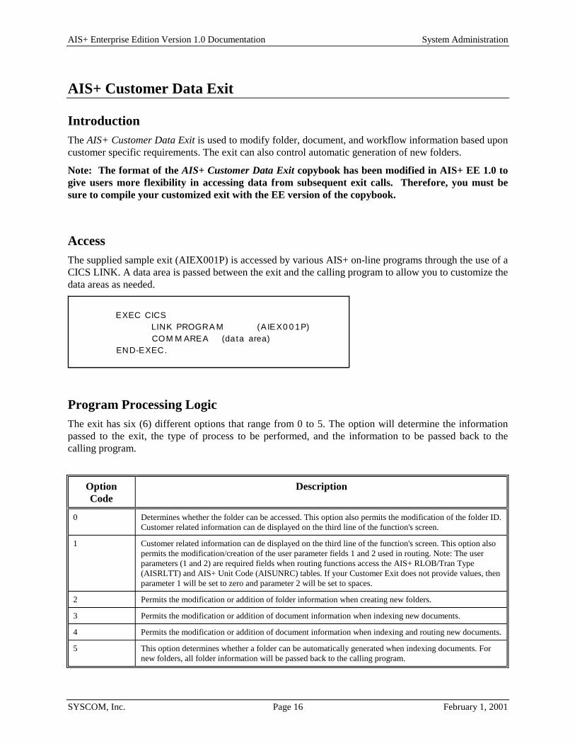
Access The supplied sample exit (AIEX001P) is accessed by various AIS+ on-line programs through the use of a CICS LINK. A data area is passed between the exit and the calling program to allow you to customize the data areas as needed.
EXEC CICSLINK PROGRA M (AIEX0 0 1P)COM M AREA (data area)
END-EXEC.
Program Processing Logic The exit has six (6) different options that range from 0 to 5. The option will determine the information passed to the exit, the type of process to be performed, and the information to be passed back to the calling program.
Option Code
Description
0 Determines whether the folder can be accessed. This option also permits the modification of the folder ID. Customer related information can de displayed on the third line of the function's screen.
1 Customer related information can de displayed on the third line of the function's screen. This option also permits the modification/creation of the user parameter fields 1 and 2 used in routing. Note: The user parameters (1 and 2) are required fields when routing functions access the AIS+ RLOB/Tran Type (AISRLTT) and AIS+ Unit Code (AISUNRC) tables. If your Customer Exit does not provide values, then parameter 1 will be set to zero and parameter 2 will be set to spaces.
2 Permits the modification or addition of folder information when creating new folders.
3 Permits the modification or addition of document information when indexing new documents.
4 Permits the modification or addition of document information when indexing and routing new documents.
5 This option determines whether a folder can be automatically generated when indexing documents. For new folders, all folder information will be passed back to the calling program.

AIS+ Enterprise Edition Version 1.0 Documentation System Administration
SYSCOM, Inc. Page 17 February 1, 2001
The installation of an AIS+ application requires profiles to be established for forms and folders prior to their being used by the application. Routing information can also be established for workflow used by the application. The profiles represent a base default for respective items. The AIS+ Customer Data Exit can be used to further customize information beyond the default profile information. The information that will be returned from the exit will depend on the option passed.
Each data field which may be changed has an associated modification flag field. When the flag contains a one (1), the calling program recognizes that the data field has been changed and handles it accordingly.
The exit will also return a code value indicating what the calling program should do upon receiving control back from the exit.
Return Code
Process
00 Proceed as normal as no changes were made.
01 Proceed as normal, but use fields that have been modified.
02 Do not route the current document, yet retain all routing values on the screen to be used for the next document. (* Currently only Index and Scan (DC06) will respond to this value *)
04 A Warning message was returned from the exit. The calling program will display the Warning message, assuming no errors exist, and continue processing normally. Any changes made in the exit will also be applied.
12 Stop processing function as an error has been encountered. The message code to be used in the display is contained in the exit's message code field.

AIS+ Enterprise Edition Version 1.0 Documentation System Administration
SYSCOM, Inc. Page 18 February 1, 2001
Parameter List Structure The table below defines the fields (format and usage) used by the various AIS+ Customer Data Exit option codes. The layout of this structure is contained in the COBOL copybook AILCSDTA.
The exit must set the parameter's flag to one (1) if the value in the parameter is changed and is to be used by the calling program.
If the exit is called multiple times within a program, data from previous calls may be available. However, the integrity of the data depends on the order of the calls and whether the data may have been overlayed.
Parameter Name Option Code
Format I/O Description
Application ID 0,1,2,3,
4,5
Bin
(2)
I The application ID code identifies the application from which the exit is being called.
Create Date 2,5 Char
(10)
I/O The create date field contains the creation date of the folder.
Create Date Flag 2,5 Char (1) O The create date flag can have two values.
0-Create date field
1-Create date field changed.
Date Format 1,2 Char
(1)
I The date format field contains the format used in the language specified for the application. The values are as follows:
1 - mm/dd/yyyy
2 - dd/mm/yyyy
3 - dd.mm.yyyy
4 - yyyy-mm-dd
5 - dd-mm-yyyy
6 - dd mm yyyy.
Document Date Received 3,4 Char
(10)
I/O The document date received field contains the date when a document was added to the application.
Document Date Received Flag
3,4 Char
(1)
O The document date received flag can have two values:
0 - Document date received field unchanged
1 - Document date received field changed
Document Description 3,4 Char
(60)
I/O The document description field contains the description given to a document.
Document Description Flag
3,4 Char
(1)
O The document description flag can have two values:
0 - Document description field unchanged
1 - Document description field changed
Document
Description Length
3,4 Bin
(2)
I The document description length field contains the length of the document description.

AIS+ Enterprise Edition Version 1.0 Documentation System Administration
SYSCOM, Inc. Page 19 February 1, 2001
Parameter Name Option Code
Format I/O Description
Document Security Class 3,4 Char
(2)
I/O The document security class field contains the security class assigned to the document.
Document Security Class Flag
3,4 Char
(1)
O The document security class flag can have two values:
0 - Document security class field unchanged
1 - Document security class field changed
File Tab 3,4 Char
(16)
I/O The file tab contains the name of the file tab in the folder under which the document is stored.
File Tab Flag 3,4 Char
(1)
O The file tab flag can have two values:
0 - File tab field unchanged
1 - File tab field changed
Folder Description 2,5 Char
(60)
I/O The folder description length field contains the descriptive text given to the folder.
Folder Description Length
2,5 Bin
(2)
I/O The folder description length field contains the actual length of the folder description.
Folder ID 0,1,2,3,
4,5
Char
(26)
I/O The folder ID field contains the unique identifier of the folder in the application.
Folder ID Flag 0,1,2,3,
4,5
Char
(1)
O The folder ID flag can have two values:
0 - Folder ID field unchanged
1 - Folder ID field changed
Folder ID Length 0,1,2,3,
4,5
Bin
(2)
I/O The folder ID length field contains the actual length of the folder ID.
Folder Secondary Index 1
2,5 Char
(40)
I/O The folder secondary index 1 field contains the value that groups folders within an application.
Folder Secondary Index 1 Flag
2,5 Char
(1)
O The folder secondary index 1 flag can have two values:
0 - Folder secondary index 1 field unchanged
1 - Folder secondary index 1 field changed
Note: If the secondary index is not defined for the application, the IBM Folder Application Facility ignores the changed folder secondary index value.
Folder Secondary Index 1 Length
2,5 Bin
(2)
I/O The folder secondary index 1 length field contains the actual length of folder secondary index 1.
Folder Secondary Index 2
2,5 Char
(40)
I/O The folder secondary index 2 field contains the value that groups folders within an application.

AIS+ Enterprise Edition Version 1.0 Documentation System Administration
SYSCOM, Inc. Page 20 February 1, 2001
Parameter Name Option Code
Format I/O Description
Folder Secondary Index 2 Flag
2,5 Char
(1)
O The folder secondary index 2 flag can have two values:
0 - Folder secondary index 2 field unchanged
1 - Folder secondary index 2 field changed
Folder Secondary Index 2 Length
2,5 Bin
(2)
I/O The folder secondary index 2 field length contains the actual length of folder secondary index 2.
Folder Secondary Index 3
2,5 Char
(40)
I/O The folder secondary index 3 field contains the value that groups folders within an application.
Folder Secondary Index 3 Flag
2,5 Char
(1)
O The folder secondary index 3 flag can have two values:
0 - Folder secondary index 3 field unchanged
1 - Folder secondary index 3 field changed
Folder Secondary Index 3 Length
2,5 Bin
(2)
I/O The folder secondary index 3 length field contains the actual length of folder secondary index 3.
Folder Security Class 2,5 Char
(2)
I/O The folder security class field contains the security class assigned to the folder.
Folder Security Class Flag
2,5 Char
(1)
O The folder security class flag can have two values:
0 - Folder security class field unchanged
1 - Folder security class field changed
Folder Type 2,3,4,5 Char
(8)
I/O The folder type field contains the value used for classifying folders.
Folder Type Flag 2,3,4,5 Char
(1)
O The folder type flag can have two values:
0 - Folder type field unchanged
1 - Folder type field changed
Form Number 3,4 Char
(16)
I/O The form number field contains a code that identifies the type of document.
Form Number Flag 3,4 Char
(1)
O The form number flag can have two values:
0 - Form number field unchanged
1 - Form number field changed
Function Code 1,2,3,
4,5
Char
(2)
I The function code field specifies the AIS+ function that called the exit.
Hold Date 4 Char
(10)
I/O The hold date field contains the date until which a routed document is on hold.
Hold Date Flag 4 Char
(1)
O The hold date flag can have two values:
0 - Hold date field unchanged
1 - Hold date field changed

AIS+ Enterprise Edition Version 1.0 Documentation System Administration
SYSCOM, Inc. Page 21 February 1, 2001
Parameter Name Option Code
Format I/O Description
Hold Time 4 Char
(8)
I/O The hold time field contains the time on the hold date until which the document is on hold.
Hold Time Flag 4 Char
(1)
O The hold time flag can have two values:
0 - Hold time field unchanged
1 - Hold time field changed
IODM ID n/a Char
(4)
I The IODM ID field is currently not being used.
Language ID 1,2,3,4,5 Char
(3)
I The language ID field contains the identifier of the language used to communicate with the user.
Line 3 Data 0,1 Char
(78)
O The line 3 data field contains the customer-related information to be displayed on the screen's third line of the calling program.
Override Max Priority 4 Bin
(3)
I/O The override max priority field contains the value used to set the priority of a routed document. If this value is set in the exit, the priority indicator is ignored.
Override Max priority Flag
4 Char
(1)
O The override max priority flag can have two values:
0 – Override max priority field unchanged
1 - Override max priority field changed
Message Code 0,1,2,3,
4,5
Char
(8)
O The message code field contains the message code generated by the user exit when the return code is 12.
Option Code 0,1,2,3,
4,5
Char
(1)
I The option code is set to a value from 0 to 5. The AIS+ calling program tells the exit what to do based on the value of the option code.
Override Priority Indicator
4 Char
(1)
I/O The override priority indicator field contains the value used to set the priority of a routed document. The values are:
0 - Normal
1 - Low
2 - Medium
3 - High
Override Priority Indicator Flag
4 Char
(1)
O The override priority indicator flag can have two values:
0 - Override priority indicator field unchanged
1 - Override priority indicator field changed

AIS+ Enterprise Edition Version 1.0 Documentation System Administration
SYSCOM, Inc. Page 22 February 1, 2001
Parameter Name Option Code
Format I/O Description
Paper Kept 3,4 Char
(1)
O The paper kept field indicates whether the physical copy of the document should be kept after the document is stored in the application.
Paper Kept Flag 3,4 Char
(1)
O The paper kept flag can have two values:
0 - Paper kept field unchanged
1 - Paper kept field changed
Return Code 0,1,2,3,
4,5
Num
(2)
O The return code must be set to one of the following values that controls the subsequent processing:
00 - Continue processing
01 - Continue processing. Use the values updated by the exit.
12 - Stop processing this function and display a message.
RLOB 4 Char
(6)
I/O The RLOB field specifies the routing line-of-business used to generate the routing destination for the document.
RLOB Flag 4 Char
(1)
O The RLOB flag can have two values:
0 - RLOB field unchanged
1 - RLOB field changed
Route Code 4 Char
(6)
I/O The route code field contains the route code value which, along with the unit code value, determines in which routing queue the document is placed .
Route Code Flag 4 Char
(1)
O The route code flag can have two values:
0 - Route code field unchanged
1 - Route code field changed
Routing Decision 4 Char
(1)
I/O The routing decision field indicates whether to add the document or add and route the document. The routing decision indicators are:
0 - Add the document to the folder
1 - Add and route the document to the folder
Routing Decision Flag 4 Char
(1)
O The routing decision flag field can have two values:
0 - Routing decision field unchanged
1 - Routing decision field changed
Supervisory Authority 1,2,3,4,5 Char
(1)
I The supervisory authority field indicates whether the user can perform supervisory functions. The supervisory authority indicators are:
N - Cannot perform supervisory functions
Y - Can perform supervisory functions

AIS+ Enterprise Edition Version 1.0 Documentation System Administration
SYSCOM, Inc. Page 23 February 1, 2001
Parameter Name Option Code
Format I/O Description
Time Format 1,2,3,4,5 Char
(1)
I The time format field contains the format used in the language specified for the application. The values are as follows:
1 - 12-hour format (hh:mm xx)
2 - 24-hour format (hh:mm )
For 12-hour time, a number from 01 to 12 specifies the hour (hh), 00 to 59 specifies the minutes (mm), and AM specifies a.m. or PM specifies p.m. (xx) The colon (:) and space ( ) are required.
For 24-hour time, a number from 00 to 23 specifies the hour (hh) and 00 to 59 specifies the minutes (mm). The colon (:) and three spaces ( ) are required.
For example, to specify 10:30 in the evening, the time parameter value is:
10:30 PM for 12-hour time
22:30 for 24-hour time.
Transaction Type 4 Char
(6)
I/O The transaction type field contains a classification of the document indicating the type of work that must be performed on the document.
Transaction Type Flag 4 Char
(1)
O The transaction type flag can have two values:
0 - Transaction type field unchanged
1 - Transaction type field changed
Unit Code 4 Bin
(4)
I/O The unit code field contains the unit code value which, along with the route code value, determines which queue the document is routed to for processing.
Unit Code Flag 4 Char
(1)
O The unit code flag can have two values:
0 - Unit code field unchanged
1 - Unit code field changed
User Date 3,4 Char
(10)
I/O The user date field contains a user-defined date associated with a document.
User Date Flag 3,4 Char
(1)
O The user date flag can have two values:
0 - User date field unchanged
1 - User date field changed
User Exit Area 3,4 Char
(20)
O This value may optionally be changed within the exit. The modified value will then be passed internally to the Storage Management Exit. This only applies to programs that call both the Customer Data Exit and the Storage Management Exit.
User Exit Data 0,2,5 Char
(20)
O This value may optionally be changed within the exit. The modified value will then be used in the creation and/or modification of both documents and folders.

AIS+ Enterprise Edition Version 1.0 Documentation System Administration
SYSCOM, Inc. Page 24 February 1, 2001
Parameter Name Option Code
Format I/O Description
User ID 1,2,3,4,5 Char
(8)
I The user ID field contains the ID that identifies the user to the AIS+ application.
User Parameter 1 1,2,3,4,5 Char (4) I/O The user parameter 1 field contains a user defined parameter used in routing. The user parameter 1 field is updated when the function code passed is "51" (Add and route a document) or "57" (Route a document).
User Parameter 1 Flag 1,2,3,4,5 Char (1) O The user Parameter 1 flag can have two values:
0 - User Parameter 1 field unchanged. Default to spaces.
1 - User Parameter 1 field changed.
User Parameter 2 1,2,3,4,5 Bin (4) I/O The user parameter 2 field contains a user defined parameter used in routing. The user parameter 2 field is updated when the function code passed is "51" (Add and route a document) or "57" (Route a document)
User Parameter 2 Flag 1,2,3,4,5 Char (1) O The user parameter 2 flag can have two values:
0 - User Parameter 2 field unchanged. Default it to zeroes.
1 - User Parameter 2 field changed.
User Security Class 1,2,3,4,5 Char (2) I The user security class field contains the security class value assigned to the user.
AIS+ Enterprise Edition Version 1.0 Documentation System Administration
SYSCOM, Inc. Page 25 February 1, 2001
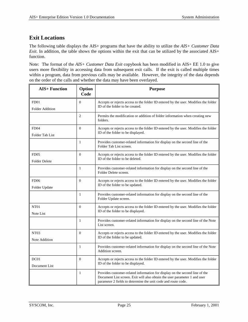
Exit Locations The following table displays the AIS+ programs that have the ability to utilize the AIS+ Customer Data Exit. In addition, the table shows the options within the exit that can be utilized by the associated AIS+ function.
Note: The format of the AIS+ Customer Data Exit copybook has been modified in AIS+ EE 1.0 to give users more flexibility in accessing data from subsequent exit calls. If the exit is called multiple times within a program, data from previous calls may be available. However, the integrity of the data depends on the order of the calls and whether the data may have been overlayed.
AIS+ Function Option Code
Purpose
FD01
Folder Addition
0 Accepts or rejects access to the folder ID entered by the user. Modifies the folder ID of the folder to be created.
2 Permits the modification or addition of folder information when creating new folders.
FD04
Folder Tab List
0 Accepts or rejects access to the folder ID entered by the user. Modifies the folder ID of the folder to be displayed.
1 Provides customer-related information for display on the second line of the Folder Tab List screen.
FD05
Folder Delete
0 Accepts or rejects access to the folder ID entered by the user. Modifies the folder ID of the folder to be deleted.
1 Provides customer-related information for display on the second line of the Folder Delete screen.
FD06
Folder Update
0 Accepts or rejects access to the folder ID entered by the user. Modifies the folder ID of the folder to be updated.
1 Provides customer-related information for display on the second line of the Folder Update screen.
NT01
Note List
0 Accepts or rejects access to the folder ID entered by the user. Modifies the folder ID of the folder to be displayed.
1 Provides customer-related information for display on the second line of the Note List screen.
NT03
Note Addition
0 Accepts or rejects access to the folder ID entered by the user. Modifies the folder ID of the folder to be updated.
1 Provides customer-related information for display on the second line of the Note Addition screen.
DC01
Document List
0 Accepts or rejects access to the folder ID entered by the user. Modifies the folder ID of the folder to be displayed.
1 Provides customer-related information for display on the second line of the Document List screen. Exit will also obtain the user parameter 1 and user parameter 2 fields to determine the unit code and route code.

AIS+ Enterprise Edition Version 1.0 Documentation System Administration
SYSCOM, Inc. Page 26 February 1, 2001
AIS+ Function Option Code
Purpose
DC02
Document Copy/Move
0 Accepts or rejects access to the folder ID entered by the user. Modifies the folder ID of the folder to be displayed.
2 The exit can change folder information if AIS+ is directed to create a folder.
DC04
Document History
1 Provides customer-related information for display on the second line of the Document History screen.
DC05
Document Modify
1 Provides customer-related information for display on the second line of the Document Modify screen.
DC05
Document Modify
(Route Document)
1 Provides the customer-related information for display on the second line of the Document Modify screen. When rerouting a document, this user exit is called to obtain user parameter 1 and user parameter 2 data which determines the unit code and route code.
DC06
Document Index and Scan
(Route Document)
0 Accepts or rejects access to the folder ID entered by the user. Modifies the folder ID of the folder to be updated.
1 Provides the customer-related information for display on the second line of the Document Index and Scan screen. When routing a document this user exit will also be called to obtain the user parameter 1 and user parameter 2 fields to determine the unit code and route code.
DC06
Document Index and Scan (Document Stored but not routed)
3 Modifies any of the information for the document that is to be added.
DC06
Document Index and Scan (Document Stored and Routed)
4 Changes the document and routing information.
DC06
Document Index and Scan
5 This exit will direct AIS+ to create a folder if one does not exist.
DC08
Scan Pending Display
1 Provides customer-related information for display on the second line of the Scan Pending Display screen.
WM01
Work With Queued Items
1 Provides the customer-related information for display on the second line of the Work With Queued Items Screen. When rerouting a document this user exit is called to obtain user parameter 1 and user parameter 2 data to determine the unit code and route code.
WM02
Queue Information
0 If a folder ID is entered, the exit will accept or reject access to the folder ID. Also optionally, the exit modifies the folder ID of the folder to be displayed.

AIS+ Enterprise Edition Version 1.0 Documentation System Administration
SYSCOM, Inc. Page 27 February 1, 2001
AIS+ Event Format Exit
Introduction The AIS+ Event Format Exit is responsible for formatting an event’s log entry that can be reviewed using the AIS+ Document History function.
An event log entry represents four (4) lines with each line having a maximum of sixty (60) characters to display. The first line represents the first 59 characters of the event description and the other three lines represent the event data (the first 180 characters). The exit can build and can send the full 253 characters for both data elements - description and data, but the log will only display as described above.
Access The exit will only be called for a given event when the event’s to-be-logged flag is turned on. The flags are contained in the AIS+ Application Profile table (AISAPPL) and are administered through the use of the AIS+ Application Profile (2) Administration function.
The supplied sample exit (AIEX013P) is accessed by various AIS+ on-line programs through the use of a CICS LINK. A data area is passed between the exit and the calling program to allow you to customize the event’s description and data areas as needed.
EXEC CICSLINK PROGRA M (AIEX0 1 3P)COM M AREA (data area)
END-EXEC.
Default Supplied Formats The default event log formats are shown in the following table:
Event Code Function Default Display 1 Store DOCUMENT SCANNED & STORED
FOLDID: xxxxxxxxxxxxxxxxxxxxxxxxx SCANNER: xxxxxxx
2 Store/Route DOCUMENT SCANNED, STORED, & ROUTED. SCANNER: xxxxxxxxxx
FOLDID: xxxxxxxxxxxxxxxxxxxxxxxxx RTCODE: xxxxxx
RTUNIT: xxxx RTLOB: xxxxxx TRANTYPE: xxxxxx
HOLD DATE: xxxxxxxxxx HOLD TIME: xxxxxxxxxx USERID: xxxxxxxx
3 Move MOVE DOCUMENT
FROM: xxxxxxxxxxxxxxxxxxxxxxxxxx TO: xxxxxxxxxxxxxxxxxxxxxxxxxx
4 Copy COPY DOCUMENT
FROM: xxxxxxxxxxxxxxxxxxxxxxxxxx TO: xxxxxxxxxxxxxxxxxxxxxxxxxx

AIS+ Enterprise Edition Version 1.0 Documentation System Administration
SYSCOM, Inc. Page 28 February 1, 2001
Event Code Function Default Display 5 Index DEFINE DOCUMENT
user comment line 1
user comment line 2
user comment line 3
user comment line 4
user comment line 5
user comment line 6
6 Reassigned DOCUMENT REASSIGNED TO: xxxxxxxx
7 Unassigned DOCUMENT UNASSIGNED
8 Route ROUTED - FOLDID: xxxxxxxxxxxxxxxxxxxxxxxxxx OPERID: xxxxxxxx
RLOB: xxxxxx TRANTYPE: xxxxxx RCODE: xxxxxx RUNIT: xxxx
user comment line 1
user comment line 2
user comment line 3
user comment line 4
user comment line 5
user comment line 6
9 Hold HELD - FOLDID: xxxxxxxxxxxxxxxxxxxxxxxxxx OPERID: xxxxxxxx
DATE: xxxxxx TIME: xxxx RCODE: xxxxxx RUNIT: xxxx
user comment line 1
user comment line 2
user comment line 3
user comment line 4
user comment line 5
user comment line 6
10 Drop DOCUMENT FILED - FOLDID: xxxxxxxxxxxxxxxxxxxxxxxxxx
RLOB: xxxxxx TRANTYPE: xxxxxx RCODE: xxxxxx RUNIT: xxxx
user comment line 1
user comment line 2
user comment line 3
user comment line 4
user comment line 5
user comment line 6
11 In Process DOCUMENT ASSIGNED - FOLDID: xxxxxxxxxxxxxxxxxxxxxxxxxx

AIS+ Enterprise Edition Version 1.0 Documentation System Administration
SYSCOM, Inc. Page 29 February 1, 2001
Event Code Function Default Display 12 Returned DOCUMENT RETURNED - FOLDID: xxxxxxxxxxxxxxxxxxxxxxxxxx
user comment line 1
user comment line 2
user comment line 3
user comment line 4
user comment line 5
user comment line 6
13 Delete DOCUMENT DELETED - FOLDID: xxxxxxxxxxxxxxxxxxxxxxxxx
xx xxxxxxxxxxxxxxxxxxxxxxxxxxxxxxxxxxxxxxxxxxxxxxxxx
14 Undelete DOCUMENT UNDELETED - FOLDID: xxxxxxxxxxxxxxxxxxxxxxxxx
xx xxxxxxxxxxxxxxxxxxxxxxxxxxxxxxxxxxxxxxxxxxxxxxxxx
15 Merge DOCUMENT MERGED - FOLDID: xxxxxxxxxxxxxxxxxxxxxxxxxx
DESTINATION OBJTKN: xxxxxxxxxxxxxxxxxxxxxxxxxx - xxxx
ORIGINAL OBJTKN: xxxxxxxxxxxxxxxxxxxxxxxxxx - xxxx
16 Move Pages xx PAGES MOVED FROM FOLDID: xxxxxxxxxxxxxxxxxxxxxxxxxx
TO FOLDID: xxxxxxxxxxxxxxxxxxxxxxxxx
user comment line 1
user comment line 2
user comment line 3
user comment line 4
user comment line 5
user comment line 6
17 Modify Object Description
MODIFY OBJECT DESCRIPTION FROM:
xxxxxxxxxxxxxxxxxxxxxxxxxxxxxxxxxxxxxxxxxxxxxxxxxxxxxxxxxxxx
user comment line 1
user comment line 2
user comment line 3
user comment line 4
user comment line 5
user comment line 6

AIS+ Enterprise Edition Version 1.0 Documentation System Administration
SYSCOM, Inc. Page 30 February 1, 2001
Event Code Function Default Display 18 Modify Object
Form Name MODIFY FORM NAME
FROM: xxxxxxxxxxxxxxxx TO: xxxxxxxxxxxxxxxx
user comment line 1
user comment line 2
user comment line 3
user comment line 4
user comment line 5
user comment line 6
19 Modify Object Receive Date
MODIFY DATE RECEIVED
OLD RECVDATE: xxxxxxxxxx NEW RECVDATE: xxxxxxxxxx
user comment line 1
user comment line 2
user comment line 3
user comment line 4
user comment line 5
user comment line 6
20 Modify Object Security Class
MODIFY SECURITY CLASS
OLD SECURITY CLASS: xx NEW SECURITY CLASS: xx
user comment line 1
user comment line 2
user comment line 3
user comment line 4
user comment line 5
user comment line 6
21 Modify Object Priority
PRIORITY CHANGED FROM: xxx TO: xxx
user comment line 1
user comment line 2
user comment line 3
user comment line 4
user comment line 5
user comment line 6

AIS+ Enterprise Edition Version 1.0 Documentation System Administration
SYSCOM, Inc. Page 31 February 1, 2001
Event Code Function Default Display 22 Modify Object
Expiration Date EXPIRATION DATE CHANGED FROM: xxxxxxxxxx TO: xxxxxxxxxx
user comment line 1
user comment line 2
user comment line 3
user comment line 4
user comment line 5
user comment line 6
23 Replace Pages PAGES REPLACED
user comment line 1
user comment line 2
user comment line 3
user comment line 4
user comment line 5
user comment line 6
24 Reorder Pages PAGES REORDERED
user comment line 1
user comment line 2
user comment line 3
user comment line 4
user comment line 5
user comment line 6
25 Insert Pages PAGES INSERTED
user comment line 1
user comment line 2
user comment line 3
user comment line 4
user comment line 5
user comment line 6

AIS+ Enterprise Edition Version 1.0 Documentation System Administration
SYSCOM, Inc. Page 32 February 1, 2001
Event Code Function Default Display 26 Delete Pages PAGES DELETED
user comment line 1
user comment line 2
user comment line 3
user comment line 4
user comment line 5
user comment line 6
27 Not In Use
28 Print DOCUMENT PRINTED OPERID: xxxxxxxx
WORKSTATION ID: xxxxxxxx PRINTER ID: xxxxxxxx
29 View DOCUMENT VIEWED OPERID: xxxxxxxx
WORKSTATION ID: xxxxxxxx
30 Offhold OFFHOLD - FOLDID: xxxxxxxxxxxxxxxxxxxxxxxxx OPERID: xxxxxxxx
31 Comments ADDITIONAL COMMENTS
user comment line 1
user comment line 2
user comment line 3
user comment line 4
user comment line 5
user comment line 6
32 Modify Object Tab Name
MODIFY TAB NAME
FROM: xxxxxxxxxxxxxxxx TO: xxxxxxxxxxxxxxxx
user comment line 1
user comment line 2
user comment line 3
user comment line 4
user comment line 5
user comment line 6

AIS+ Enterprise Edition Version 1.0 Documentation System Administration
SYSCOM, Inc. Page 33 February 1, 2001
Parameter List Structure The supplied default formats are only a recommendation. You can create your own format for an event's log with the information supplied by AIS+ (through the supplied AISW013 COBOL II copybook). All events will not carry the same information; therefore, you will be limited to what you can build by the information supplied for a given event.
The only requirement the exit must satisfy is that the event description and the event data must contain data when returning back to the calling AIS+ function.
Program Processing Logic The event's to-be-logged flag is first checked to determine if the exit will be called. The flags are contained in the AIS+ Application Profile table (AISAPPL) and are administered through the use of the AIS+ Application Profile (2) Administration function. If the flag is set to N, the exit will not be called and the event not logged. If the flag is set to Y, then the exit will be called and an event will be logged if information is passed back from the Exit.
The process does not use return codes or status switches to indicate a successful return. Instead, the calling program will check for non-zero lengths in the length fields (data and description) to determine if the IBM FAF API process for adding an event (ADDEVENT) will be executed.

AIS+ Enterprise Edition Version 1.0 Documentation System Administration
SYSCOM, Inc. Page 34 February 1, 2001
Exit Locations The following table displays the AIS+ programs that have the ability to utilize the AIS+ Event Format Exit. In addition, the table shows the events that can be logged for each program.
Program Event
AIDC001P 08 - Route Document 09 - Route and Hold Document 15 - Merge Document 28 - Print Document 29 - View Document
AIDC002P 03 - Move Document 04 - Copy Document
AIDC003P 13 - Logical Delete 14 - Logical Un-delete
AIDC005P 08 - Route Document 09 - Pend/Hold Document 16 - Move Pages 17 - Modify Description 18 - Modify Form Name 19 - Modify Receive Date 20 - Modify Security Class 21 - Modify Priority 22 - Modify Expiration Date 23 - Replace Pages 24 - Reorder Pages 25 - Insert Pages 26 - Delete Pages 30 - Take Document off Hold/Pend 31 - Additional Comments 32 - Modify Tab Name
AIDC006P 05 - Index Document
AIWM001P 08 - Route Document 09 - Pend/Hold Document 10 - Drop Document 11 - In Process Document 12 - Return Document 28 - Print Document 29 - View Document
AIWM002P 06 - Reassign Document 07 - Unassign Document 09 - Pend/Hold Document 29 - View Document 30 - Take Document off Hold/Pend
AIRT001P 01 - Document Scanned & Stored 02 - Document Scanned, Stored, & Routed 30 - Take Document off Hold/Pend

AIS+ Enterprise Edition Version 1.0 Documentation System Administration
SYSCOM, Inc. Page 35 February 1, 2001
AIS+ Routing Data Exit
Introduction The AIS+ Routing Data Exit is used to modify routing requirements for a document prior to being scanned or during a re-route function.
Access The supplied sample exit (AIEX003P) is accessed by various AIS+ on-line programs through the use of a CICS LINK. A data area is passed between the exit and the calling program to allow you to customize the data areas as needed.
EXEC CICSLINK PROGRA M (AIEX0 0 3P)COM M AREA (data area)
END-EXEC.
Program Processing Logic The installation of an AIS+ application requires profiles to be established for forms prior to their being used by the application. Part of the profile includes routing information for when the document initially enters the system. The AIS+ Routing Data Exit can be used to further customize information beyond the default profile information. The exit can also be used to modify the path a document will follow during a re-route function.
Each returned data field has an associated modification flag field. When the flag contains a one (1), the calling program recognizes that the information in the data field has been changed and needs to be processed.
The exit will also return a code value indicating what the calling program should do upon returning control back to the calling program.
Return Code
Process
00 Proceed as normal as no changes were made.
01 Proceed as normal, but use fields that have been modified.
12 Stop processing function as an error has been encountered. The message code to be used in the display is contained in the exit's message code field.

AIS+ Enterprise Edition Version 1.0 Documentation System Administration
SYSCOM, Inc. Page 36 February 1, 2001
Parameter List Structure The table below defines the fields (format and usage) used by the various AIS+ Routing Data Exit option codes. The parameter list layout is contained in the COBOL copybook AILROUTE.
The exit must set the parameter's flag to one (1) if the value in the parameter is changed and is to be used by the calling program.
Parameter Name Format I/O Description
Aging Date Char
(10)
I/O The aging date is used to calculate the priority of a document.
Aging Date Flag Char
(1)
O The aging date flag can have two values:
0 - Aging date field unchanged
1 - Aging date field changed
Application ID Code Bin
(2)
I The application ID code field identifies the application from which the exit is being called.
Assigned User ID Char
(8)
I/O The assigned user ID field contains the user ID of the employee assigned to process the document.
Assigned User ID Flag Char
(1)
O The assigned user ID flag can have two values:
0 - User ID field unchanged
1 - User ID field changed
Date Format Char
(1)
I The date format field contains the format used in the language specified for the application. The values are as follows:
1 - mm/dd/yyyy
2 - dd/mm/yyyy
3 - dd.mm.yyyy
4 - yyyy-mm-dd
5 - dd-mm-yyyy
6 - dd mm yyyy
Document Date Received Char
(10)
I The document date received contains the date when the document was added to the AIS+ system.
Document Security Class Char
(2)
I The document security class field contains the security class assigned to the document.
Expiration Date Char
(10)
I/O The expiration date field contains the last date that the document must be processed.
Expiration Date Flag Char
(1)
O The expiration date flag can have two values:
0 - Date field unchanged
1 - Date field changed
File Tab Char I The file tab field contains the name of the file tab for which the d i d

AIS+ Enterprise Edition Version 1.0 Documentation System Administration
SYSCOM, Inc. Page 37 February 1, 2001
Parameter Name Format I/O Description
(16) document is stored.
Folder ID Char
(26)
I The folder ID field contains the unique identifier of the folder in the application.
Folder ID Length Bin
(2)
I The folder ID length contains the actual length of the folder ID.
Form Number Char
(16)
I The form number field contains a code that identifies the type of document.
Function Code Char
(2)
I The function code field specifies the function that called the exit.
Hold Date Char
(10)
I/O The hold date field contains a date until which a routed document is on hold.
Hold Date Flag Char
(1)
O The hold date flag can have two values:
0 - Hold Date field unchanged
1 - Hold Date field changed
Hold Time Char
(8)
I/O The hold time field contains the time of the hold date until which a routed document is on hold.
Hold Time Flag Char
(1)
O The hold time flag can have two values:
0 - Hold Time field unchanged
1 - Hold Time field changed
Language ID Char
(3)
I
The language ID field is not used in current versions of AIS+.
Message Code Char
(8)
O The message code field contains the message code generated by the user exit when the return code is 12.
Number of Documents Num
(1)
I The number of documents field shows the number of documents for which the exit is going to provide routing information.
Override Priority Indicator
Char
(1)
I The override priority indicator flag can have two values:
0 - Override priority indicator field unchanged
1 - Override priority indicator field changed
Priority Bin
(2)
I/O The priority field contains a value from 0 to 999 . A document is selected for processing depending on the priority value.
Priority Flag Char
(1)
O The priority flag can have two values:
0 - Override priority unchanged
1 - Override priority field changed
Return Code Num
(2)
O The return code must be set to one of the following values that controls subsequent processing:
00 - Continue processing
01 - Continue processing. Use the values updated by the

AIS+ Enterprise Edition Version 1.0 Documentation System Administration
SYSCOM, Inc. Page 38 February 1, 2001
Parameter Name Format I/O Description exit.
12 - Stop processing this function and display a message.
RLOB Char
(6)
I/O The RLOB field specifies the routing line of business used to generate the routing destination for a document.
RLOB Flag Char
(1)
O The RLOB flag can have two values:
0 - RLOB unchanged
1 - RLOB changed
Route Code Char
(6)
I/O The route code field contains the route code value. This field, along with the unit code value, determines in which routing queue the document is placed.
Route Code Flag Char
(1)
O The route code flag can have two values:
0 - Route code unchanged
1 - Route code changed
Supervisory Authority Char
(1)
I The supervisory authority is currently not being used.
Time Format Char
(1)
I The time format field contains the format used in the language specified for the application. The values are as follows:
1 - 12-hour format (hh:mm xx)
2 - 24-hour format (hh:mm)
For 12 hour time, a number from 01 to 12 specifies the hour (hh), 00 to 59 specifies the minutes (mm), and AM specifies a.m. or PM specifies p.m. (xx) The colon (:) and three spaces ( ) are required.
For example, to specify 10:30 in the evening, the time parameter value is:
10:30 PM for 12-hour time
22:30 for 24-hour time.
Transaction Type Char
(6)
I/O The transaction type field contains a classification of the document indicating the type of work that must be performed on the document.
Transaction Type Flag Char
(1)
O The transaction type flag can have two values:
0 - Transaction type unchanged
1 - Transaction type changed
Unit Code Bin
(4)
I/O The unit code field contains the unit code value. This field, along with the route code value, determines which queue the document is routed to for processing.
Unit Code Flag Char
(1)
O The Unit Code flag can have two values:
0 - Unit code unchanged
1 - Unit code changed
User Exit Area Char
(20)
I/O
The user exit area field contains the data passed from one user exit to the next.

AIS+ Enterprise Edition Version 1.0 Documentation System Administration
SYSCOM, Inc. Page 39 February 1, 2001
Parameter Name Format I/O Description
User ID Char
(8)
I The user ID field contains the sign-on ID of the person performing the function.
User Parameter 1 Char
(4)
I/O The user parameter 1 field contains a user-defined parameter.
User Parameter 1 Flag Char
(1)
O The user parameter 1 flag can have two values:
0 - Parameter 1 unchanged
1 - Parameter 1 changed
User Parameter 2 Bin
(4)
I/O
The user parameter 2 field contains a user-defined parameter.
User Parameter 2 Flag Char
(1)
O The User Parameter 2 flag can have two values:
0 - Parameter 2 unchanged
1 - Parameter 2 changed
User Security Class Char
(2)
I The user security class field contains the security class assigned to the user.

AIS+ Enterprise Edition Version 1.0 Documentation System Administration
SYSCOM, Inc. Page 40 February 1, 2001
Exit Locations The following table displays the AIS+ programs that have the ability to utilize the AIS+ Routing Data Exit. In addition, the table shows the options within the exit that can be utilized by the associated AIS+ function.
AIS+ Function Purpose
DC01
Document List
(Reroute a Document)
Changes the routing information of a document before placing the document in the routing queue.
DC01
Document List
(Send Work)
Changes the routing information of a document before placing the document in the routing queue.
DC05
Document Modify
(Route Document)
Changes the routing information of a document before placing the document in the routing queue.
DC06/RT01
Document Index & Scan
Changes any of the routing information before placing the document in the routing queue. AIS+ calls the routing data exit after the document is indexed.
WM01
Work With Queued Items
(Reroute Document)
Changes the routing information of a document before placing the document in the routing queue.

AIS+ Enterprise Edition Version 1.0 Documentation System Administration
SYSCOM, Inc. Page 41 February 1, 2001
AIS+ Security Control Exit
Introduction The AIS+ Security Control Exit is used to further validate an operator's sign-on beyond the AIS+ Operator Profile defaults.
Access The supplied sample exit (AIEX005P) is accessed by various AIS+ on-line programs through the use of a CICS LINK. A data area is passed between the exit and the calling program to allow you to customize the data areas as needed.
EXEC CICSLINK PROGRA M (AIEX0 0 5P)COM M AREA (data area)
END-EXEC.
Program Processing Logic The exit will return a code value indicating what the calling program should do upon returning control back to the calling program.
Return Code
Process
00 Proceed as normal as no errors were encountered.
01 Proceed as normal, but use fields that have been modified
12 Stop processing function as an error has been encountered. The message code to be used in the display is contained in the exit's message code field.

AIS+ Enterprise Edition Version 1.0 Documentation System Administration
SYSCOM, Inc. Page 42 February 1, 2001
Parameter List Structure The table below defines the fields (format and usage) used by the AIS+ Security Control Exit. The actual parameters for the are contained in the COBOL copybook AILSCRTY.
Note: The Security Control Exit is called when signing on to AIS+ and also when signing off from AIS+. When signing on to AIS+, the security control exit is called with function code ‘00’ or '01' (upon initial execution of the program if the Operator ID is provided, the exit is called with function code ‘00’, otherwise it is called with function code ‘01’), and when signing off from AIS+, the security control exit is called with function code '02'. AIS+ allows you to modify the operator ID, password, menu flag, application ID and the workstation ID only when the security control exit is called with function codes ‘00’ and '01'. The Error flags and the change flags apply to function codes ‘00’ and '01' only.
Parameter Name Format I/O FunctionCode
Description
Function Code Char
(2)
I 00, 01, 02 The function code field specifies the function that called the exit.
01 - Sign-on
02 - Sign-off
Return Code
(RETURN-CODE)
Num
(4)
I 00, 01 The return code must be set to one of the following values that controls the subsequent processing:
00 - Continue processing
01 - Continue processing, but use fields that have been modified
12 - Stop processing this function and display a message.
Message Code Char
(8)
O 00, 01, 02 The message code field contains the message code generated by the user exit when the return code is 12.
Operator ID Char
(8)
I/O 00, 01, 02 The operator ID of the person logging on to AIS+.
Input only for function code '02'
Operator Change Flag Char
(1)
O 00, 01 The operator Change flag can have two values:
0 - The Operator ID field unchanged
1 - The Operator ID field changed
When the change flag is set to '1', the new operator ID is displayed on the sign-on screen. This only applies to function codes ‘00’ and '01'.
Operator Error Flag Char
(1)
O 00, 01 The operator Error flag can have two values:
0 - The Operator ID field has no error
1 - The Operator ID field has an error
When the error flag is set to '1', the operator ID field will be highlighted and the cursor will be placed on that field. This only applies to function codes ‘00’ and '01'.
Password Char I/O 00, 01, 02 The operator password of the person logging on to AIS+.

AIS+ Enterprise Edition Version 1.0 Documentation System Administration
SYSCOM, Inc. Page 43 February 1, 2001
Parameter Name Format I/O FunctionCode
Description
(8) Input only for function code '02'.
Password Change Flag Char
(1)
O 00, 01 The password change flag can have two values:
0 - The password field unchanged
1 - The password field changed
When the change flag is set to '1', the new password value is used to search the AIS+ operator profile table.
Password Error Flag Char O 00, 01 The password error flag can have two values:
0 - The password field has no error
1 - The password field has an error
When the error flag is set to '1', the cursor is placed on the password field.
Application ID
Char
(2)
I/O 00, 01, 02 The application ID field contains the code identifying the application from which the exit is being called.
Input only for function code '02'.
Application ID Change Flag
Char
(1)
O 00, 01 The Application ID change flag can have two values:
0 - The Application ID field unchanged
1 - The Application ID field changed
When the change flag is set to '1', the new application ID is displayed on the sign-on screen. This only applies to function codes ‘00’ and '01'.
Application ID Error Flag
Char
(1)
O 00, 01 The Application ID Error flag can have two values:
0 - The Application ID field has no error
1 - The Application ID field has an error
When the error flag is set to '1', the application id field will be highlighted and the cursor will be placed on that field. This only applies to function codes ‘00’ and '01'.
Workstation ID Char
(8)
I/O 00, 01 The Workstation ID of the terminal where the images will be displayed.
Workstation ID change flag
Char
(1)
O 00, 01 The Workstation ID change flag can have two values:
0 - The workstation ID field unchanged
1 - The workstation ID field changed
When the change flag is set to '1', the new workstation ID is displayed on the sign-on screen. This only applies to function codes ‘00’ and '01'.
Workstation ID error flag Char
(1)
O 00, 01 The Workstation ID error flag can have two values:
0 - The Workstation ID has no error
1 - The Workstation ID has an error
When the error flag is set to '1', the workstation ID field will be highlighted and the cursor will be placed on that field. This only applies to function codes ‘00’ and '01'.

AIS+ Enterprise Edition Version 1.0 Documentation System Administration
SYSCOM, Inc. Page 44 February 1, 2001
Parameter Name Format I/O FunctionCode
Description
Menu Switch Char
(1)
I/O 00, 01 The Menu Switch indicates whether the main menu be displayed after the operator is successfully logged on to AIS+.
Menu Switch Change Flag
Char
(1)
O 00, 01 The Menu Switch change flag can have two values:
0 - The menu switch unchanged
1 - The menu switch changed
When the change flag is set to '1', the new menu switch is displayed on the sign-on screen. This only applies to function codes ‘00’ and '01'.
Menu Switch Error Flag Char
(1)
O 00, 01 The Menu Switch error flag can have two values:
0 - The Menu Switch has no error
1 - The Menu Switch has an error
When the error flag is set to '1', the menu switch field will be highlighted and the cursor will be placed on that field. This only applies to function codes ‘00’ and '01'.
Password change switch Char
(1)
I/O 00, 01 The password change flag must be set to 'Y' to allow the password to be changed for that operator ID.
The valid values for the Operator Change Flag are 'Y', 'N' or a space.
Password switch change flag
Char
(1)
O 00, 01 The Password switch change flag can have two values:
0 - The password switch unchanged
1 - The password switch changed
Password switch error flag
Char
(1)
O 00, 01 The Password switch error flag can have two values:
0 - The password switch has no error
1 - The password switch has an error
New password-1 Char
(8)
I/O 00, 01 The new password for the operator ID. The new password is passed to the security exit only when the password change switch is 'Y'
New password-1 change flag
Char
(1)
O 00, 01 The new password-1 change flag can have two values:
0 - The password-1 is unchanged
1 - The password-1 is changed. The password switch must be set to 'y'.
New password-1 error flag
Char
(1)
O 00, 01 The new password-1 error flag can have two values:
0 - The password-1 has no error
1 - The password-1 has an error
New password-2 Char
(8)
I/O 00, 01 The password -2 is for verifying the new password for the operator ID. The new password is passed to the security exit only when the password change switch is 'Y'. The new password 1 must be the same as new password 2.
New password-2 change flag
Char
(1)
O 00, 01 The new password-2 change flag can have two values:
0 - The password-2 is unchanged
1 - The password-2 is changed. The password
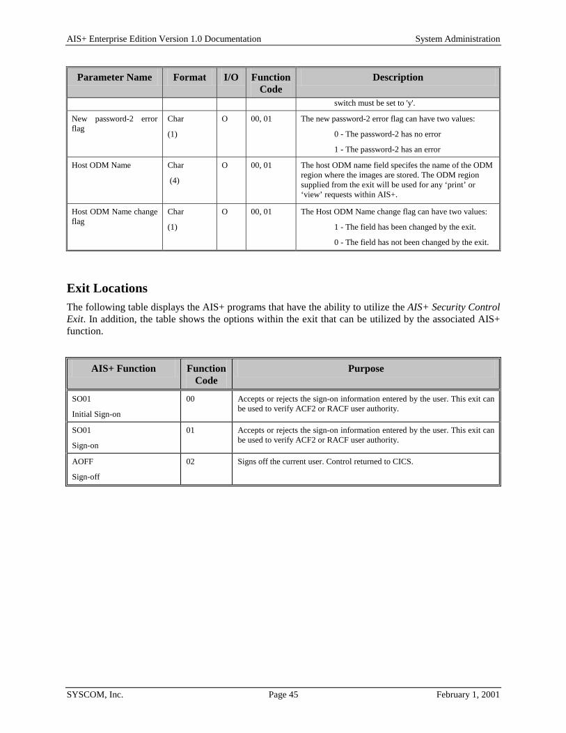
AIS+ Enterprise Edition Version 1.0 Documentation System Administration
SYSCOM, Inc. Page 45 February 1, 2001
Parameter Name Format I/O FunctionCode
Description
switch must be set to 'y'.
New password-2 error flag
Char
(1)
O 00, 01 The new password-2 error flag can have two values:
0 - The password-2 has no error
1 - The password-2 has an error
Host ODM Name Char
(4)
O 00, 01 The host ODM name field specifes the name of the ODM region where the images are stored. The ODM region supplied from the exit will be used for any ‘print’ or ‘view’ requests within AIS+.
Host ODM Name change flag
Char
(1)
O 00, 01 The Host ODM Name change flag can have two values:
1 - The field has been changed by the exit.
0 - The field has not been changed by the exit.
Exit Locations The following table displays the AIS+ programs that have the ability to utilize the AIS+ Security Control Exit. In addition, the table shows the options within the exit that can be utilized by the associated AIS+ function.
AIS+ Function FunctionCode
Purpose
SO01
Initial Sign-on
00 Accepts or rejects the sign-on information entered by the user. This exit can be used to verify ACF2 or RACF user authority.
SO01
Sign-on
01 Accepts or rejects the sign-on information entered by the user. This exit can be used to verify ACF2 or RACF user authority.
AOFF
Sign-off
02 Signs off the current user. Control returned to CICS.
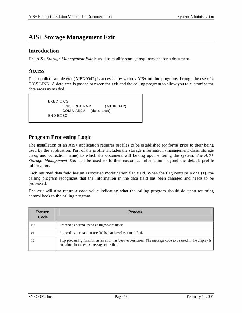
AIS+ Enterprise Edition Version 1.0 Documentation System Administration
SYSCOM, Inc. Page 46 February 1, 2001
AIS+ Storage Management Exit
Introduction The AIS+ Storage Management Exit is used to modify storage requirements for a document.
Access The supplied sample exit (AIEX004P) is accessed by various AIS+ on-line programs through the use of a CICS LINK. A data area is passed between the exit and the calling program to allow you to customize the data areas as needed.
EXEC CICSLINK PROGRA M (AIEX0 0 4P)COM M AREA (data area)
END-EXEC.
Program Processing Logic The installation of an AIS+ application requires profiles to be established for forms prior to their being used by the application. Part of the profile includes the storage information (management class, storage class, and collection name) to which the document will belong upon entering the system. The AIS+ Storage Management Exit can be used to further customize information beyond the default profile information.
Each returned data field has an associated modification flag field. When the flag contains a one (1), the calling program recognizes that the information in the data field has been changed and needs to be processed.
The exit will also return a code value indicating what the calling program should do upon returning control back to the calling program.
Return Code
Process
00 Proceed as normal as no changes were made.
01 Proceed as normal, but use fields that have been modified.
12 Stop processing function as an error has been encountered. The message code to be used in the display is contained in the exit's message code field.

AIS+ Enterprise Edition Version 1.0 Documentation System Administration
SYSCOM, Inc. Page 47 February 1, 2001
Parameter List Structure The table below defines the fields (format and usage) used by the various AIS+ Storage Management Exit option codes. The parameter list layout is contained in the COBOL copybook AILSTMGT.
The exit must set the parameter's flag to one (1) if the value in the parameter is changed and is to be used by the calling program.
Parameter Name Format I/O Description
Application ID Code Bin
(2)
I The application ID code identifies the application from which the exit is being called.
Collection
Name
Char
(44)
I/O The collection name field contains the name that identifies the collection of objects stored. This name is used to reference the storage group name, management class name, and storage class name for the document. The IBM Object Access method needs the collection name to determine where to store and retrieve documents.
Collection
Name Flag
Char
(1)
O The collection name flag can have two values:
O - Collection name field unchanged
1 - Collection name field changed
Create Site Char
(8)
I/O The create site field contains the symbolic name of the IBM IODM CICS region where the document should be scanned.
Create Site Flag Char
(1)
O The create site flag can have two values:
O - Create site field unchanged
1 - Create site field changed
Date Format Char
(1)
I The date format field contains the format used in the language specified for the application. The values are as follows:
1 - mm/dd/yyyy
2 - dd/mm/yyyy
3 - dd.mm.yyyy
4 - yyyy-mm-dd
5 - dd-mm-yyyy
6 - dd mm yyyy
Document Date Filed Char
(10)
I The document date filed field contains the date the document was filed in the application.
Document Date Received Char
(10)
I The document date received field contains the date when a document was added to the application.
Document Description Char
(60)
I The document description field contains the description given to a document.
Document Description
Length
Bin
(2)
I The document description length field contains the length of the document description.
Document Security Class Char I The document security class field contains the security class assigned h d
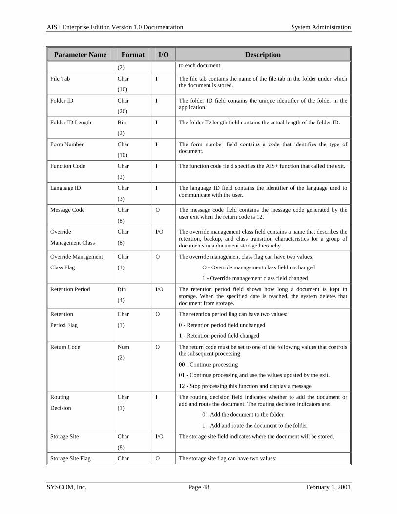
AIS+ Enterprise Edition Version 1.0 Documentation System Administration
SYSCOM, Inc. Page 48 February 1, 2001
Parameter Name Format I/O Description
(2) to each document.
File Tab Char
(16)
I The file tab contains the name of the file tab in the folder under which the document is stored.
Folder ID Char
(26)
I The folder ID field contains the unique identifier of the folder in the application.
Folder ID Length Bin
(2)
I The folder ID length field contains the actual length of the folder ID.
Form Number Char
(10)
I The form number field contains a code that identifies the type of document.
Function Code Char
(2)
I The function code field specifies the AIS+ function that called the exit.
Language ID Char
(3)
I The language ID field contains the identifier of the language used to communicate with the user.
Message Code Char
(8)
O The message code field contains the message code generated by the user exit when the return code is 12.
Override
Management Class
Char
(8)
I/O The override management class field contains a name that describes the retention, backup, and class transition characteristics for a group of documents in a document storage hierarchy.
Override Management
Class Flag
Char
(1)
O The override management class flag can have two values:
O - Override management class field unchanged
1 - Override management class field changed
Retention Period Bin
(4)
I/O The retention period field shows how long a document is kept in storage. When the specified date is reached, the system deletes that document from storage.
Retention
Period Flag
Char
(1)
O The retention period flag can have two values:
0 - Retention period field unchanged
1 - Retention period field changed
Return Code Num
(2)
O The return code must be set to one of the following values that controls the subsequent processing:
00 - Continue processing
01 - Continue processing and use the values updated by the exit.
12 - Stop processing this function and display a message
Routing
Decision
Char
(1)
I The routing decision field indicates whether to add the document or add and route the document. The routing decision indicators are:
0 - Add the document to the folder
1 - Add and route the document to the folder
Storage Site Char
(8)
I/O The storage site field indicates where the document will be stored.
Storage Site Flag Char O The storage site flag can have two values:

AIS+ Enterprise Edition Version 1.0 Documentation System Administration
SYSCOM, Inc. Page 49 February 1, 2001
Parameter Name Format I/O Description
(1) 0 - Storage site field unchanged
1 - Storage site field changed
Temporary ID Format Char
(1)
I The temporary document ID format contains a value that determines how ImagePlus creates the temporary document ID. The values are as follows:
1 - ImagePlus uses the value of the folder ID
2 - ImagePlus uses the value of the folder ID with a
randomly generated three-digit number
3 - ImagePlus randomly generates a six-digit number
4 - ImagePlus concatenates the temporary ID prefix with
a randomly generated six-digit number
Temporary ID Prefix Char
(1)
I The temporary ID prefix field contains a value that is used to create the temporary document ID.
Terminal IODM ID Char
(4)
I This field is currently not being used.
User Date Char
(10)
I The user date area field is used by the user to specify a date for the document.
User Exit Area Char
(20)
I/O This value is supplied during the addition or modification of documents. The customer may optionally modify this value within the exit.
User ID Char
(8)
I The user ID field contains the ID of the user that is calling the exit.
User Parameter
1
Char
(4)
I The user parameter 1 field contains a user-defined parameter.
User Parameter
2
Bin
(4)
I The user parameter 2 field contains a user-defined parameter.
User Security Class Char
(2)
I The user security class field contains the security class value assigned to the user.
Workstation ID Char
(8)
I The workstation ID field contains the code that identifies the workstation used to display the image part of the document.

AIS+ Enterprise Edition Version 1.0 Documentation System Administration
SYSCOM, Inc. Page 50 February 1, 2001
Exit Locations The following table displays the AIS+ programs that have the ability to utilize the AIS+ Storage Management Exit. In addition, the table shows the options within the exit that can be utilized by the associated AIS+ function.
AIS+ Function Purpose
DC05
Document Modify
(Move Pages)
When moving pages from one folder to another, this exit is invoked to provide storage management parameters for the new document.
DC06
Document Index and Scan
Provides the collection name and the storage management values of the document. AIS+ uses this information to store the document.

AIS+ Enterprise Edition Version 1.0 Documentation System Administration
SYSCOM, Inc. Page 51 February 1, 2001
AIS+ Validate Data Exit
Introduction The AIS+ Validate Data Exit is used to validate folder, document, and workflow information based upon customer specific requirements.
Access The supplied sample exit (AIEX002P) is accessed by various AIS+ on-line programs through the use of a CICS LINK. A data area is passed between the exit and the calling program to allow you to customize the data areas as needed.
EXEC CICSLINK PROGRA M (AIEX0 0 2P)COM M AREA (data area)
END-EXEC.
Program Processing Logic The exit has five (5) different options that range from 1 to 5. The option will determine the information passed to the exit, the type of process performed, and the information passed back to the calling program.
Option Code Description
1 The exit will validate the folder information prior to the folder being created.
2 The exit will validate the folder information prior to the folder being updated.
3 The exit will validate the folder ID and the document information prior to adding the document.
4 The exit will validate the folder ID and the document information prior to updating the document.
5 The exit will validate the folder ID and the document information, including routing information, prior to adding the document to the folder and routed.
The installation of an AIS+ application requires profiles to be established for forms and folders prior to their being used by the application. Routing information can also be established for workflow used by the application. The profiles represent a base default for respective items. The AIS+ Validate Data Exit can be used to validate information prior to adding or updating folder and/or document information. The option in use determines the information that will be returned from the exit.
The exit will return a code value indicating what the calling program should do after the exit is invoked.

AIS+ Enterprise Edition Version 1.0 Documentation System Administration
SYSCOM, Inc. Page 52 February 1, 2001
Return Code
Process
00 Proceed as normal as no errors were encountered.
04 A Warning message was returned from the exit. The calling program will display the Warning message, assuming no errors exist, and continue processing normally. Any changes made in the exit will also be applied.
12 Stop processing function as an error has been encountered. The message code to be used in the display is contained in the exit's message code field.

AIS+ Enterprise Edition Version 1.0 Documentation System Administration
SYSCOM, Inc. Page 53 February 1, 2001
Parameter List Structure The table below defines the fields (format and usage) used by the various AIS+ Validate Data Exit option codes. The parameter list layout is contained in the COBOL copybook AILVLDT.
Parameter Name Option Code
Format I/O Description
Aging Date
5 Char
(10)
I The date from which aging of a document is based.
Application ID 1,2,3,4,5 Bin
(2)
I The application ID code field identifies the application from which the exit is being called.
Assigned User ID 5 Char
(8)
I The assigned user ID field contains the ID of the user assigned to work on the document.
Awake Document 5 Char
(1)
I The awake document field indicates whether the suspended documents in the folder should be made available for processing. The awake document indicators are:
0 - Suspended documents in the folder should not be made available for processing
1 - Suspended documents in the folder should be made available for processing
Create Date 1,2 Char
(10)
I The create date field contains the date the folder was created. This date must be earlier than or the same as the system-generated date.
Date Format 1,2,3,4,5 Char
(1)
I The date format field contains the format used in the language specified for the application. The values are as follows:
1 - mm/dd/yyyy 2 - dd/mm/yyyy 3 - dd.mm.yyyy 4 - yyyy-mm-dd 5 - dd-mm-yyyy 6 - dd mm yyyy
Document Date Filed 3,4 Char
(10)
I The document date filed field contains the date the document was filed in the application.
Document Date Received 3,4,5 Char
(10)
I The document date received field contains the date when a document was added to the application.
Document Description 3,4,5 Char
(60)
I The document description field contains the description given to a document.
Document Description
Length
3,4,5 Bin
(2)
I The document description length field contains the length of the document description.
Document Security Class 3,4,5 Char I The document security class field contains the security class assigned to each document.

AIS+ Enterprise Edition Version 1.0 Documentation System Administration
SYSCOM, Inc. Page 54 February 1, 2001
Parameter Name Option Code
Format I/O Description
(2)
Expiration Date 5 Char
(10)
I The expiration date field contains the last date by which the document must be processed.
File Tab 3,4,5 Char
(16)
I The file tab contains the name of the file tab in the folder under which the document is stored.
Folder Description 1,2 Char
(60)
I The folder description length field contains the actual length of the folder description.
Folder Description Length
1,2 Bin
(2)
I The folder description length field contains the actual length of the folder description.
Folder ID 1,2,3,4,5 Char
(26)
I The folder ID field contains the unique identifier of the folder in the application.
Folder ID Length 1,2,3,4,5 Bin
(2)
I The folder ID length field contains the actual length of the folder ID.
Folder Secondary Index 1
1,2 Char
(40)
I The folder secondary index 1 field contains the value that groups folders within an application.
Folder Secondary Index 1 Length
1,2 Bin
(2)
I The folder secondary index 1 length field contains the actual length of folder secondary index 1.
Folder Secondary Index 2
1,2 Char
(40)
I The folder secondary index 2 field contains the value that groups folders within an application.
Folder Secondary Index 2 Length
1,2 Bin
(2)
I The folder secondary index 2 field length contains the actual length of folder secondary index 2.
Folder Secondary Index 3
1,2 Char
(40)
I The folder secondary index 3 field contains the value that groups folders within an application.
Folder Secondary Index 3 Length
1,2 Bin
(2)
I The folder secondary index 3 length field contains the actual length of folder secondary index 3.
Folder Security Class 1,2 Char
(2)
I The folder security class field contains the security class assigned to the folder.
Folder Type 1,2
Char
(8)
I The folder type field contains the value used for classifying folders.
Form Number 3,4,5 Char
(16)
I The form number field contains a code that identifies the type of document.
Function Code 1,2,3,4,5 Char
(2)
I The function code field specifies the AIS+ function that called the exit.
Hold Date 5 Char
(10)
I The hold date field contains the date until which a document is on hold.
Hold Time 5 Char I The hold time field contains the time on the hold date il hi h h d i h ld

AIS+ Enterprise Edition Version 1.0 Documentation System Administration
SYSCOM, Inc. Page 55 February 1, 2001
Parameter Name Option Code
Format I/O Description
(8) until which the document is on hold.
Language ID 1,2,3,4,5 Char
(3)
I The language ID field contains the identifier of the language used to communicate with the user.
Message Code 1,2,3,4,5 Char
(8)
O The message code field contains the message code generated by the user exit when the return code is 12.
Option Code 1,2,3,4,5 Num
(1)
I The option code is set to a value from 1 to 5. The AIS+ calling program tells the Validate Data exit what to do based on the value of the option code field.
Override Priority Indicator
5 Char
(1)
I The override priority indicator field contains the value used to set the priority of a routed document. The values are:
0 - Normal
1 - Low
2 - Medium
3 - High
Return Code 1,2,3,4,5 Num
(2)
O The return code must be set to one of the following values that controls the subsequent processing:
00 - Continue processing
12 - Stop processing this function and display a message.
RLOB 5 Char
(6)
I The RLOB field specifies the routing line-of-business used to generate the routing destination for the document.
Route Code 5 Char
(6)
I The route code field contains the route code value which, along with the unit code value, determines in which routing queue the document is placed.
Routing
Decision
5 Char
(1)
I The routing decision field indicates whether to add the document or add and route the document. The routing decision indicators are:
0 - Add the document to the folder
1 - Add and route the document to the folder
Supervisory Authority 1,2,3,4,5 Char
(1)
I The supervisory authority field indicates whether the user can perform supervisory functions. The supervisory authority indicators are:
N - Cannot perform supervisory functions
Y - Can perform supervisory functions
Time Format 1,2,3,4,5 Char
(1)
I The time format field contains the format used in the language specified for the application. The values are as follows:
1 - 12-hour format (hh:mm xx)
2 - 24-hour format (hh:mm)
For 12-hour time, a number from 01 to 12 specifies the hour (hh), 00 to 59 specifies the minutes (mm), and AM

AIS+ Enterprise Edition Version 1.0 Documentation System Administration
SYSCOM, Inc. Page 56 February 1, 2001
Parameter Name Option Code
Format I/O Description
specifies a.m. or PM specifies p.m. (xx) The colon (:) and space ( ) are required.
For 24-hour time, a number from 00 to 23 specifies the hour (hh) and 00 to 59 specifies the minutes (mm). The colon (:) and three spaces ( ) are required.
For example, to specify 10:30 in the evening, the time parameter value is:
10:30 PM for 12-hour time
22:30 for 24-hour time.
Transaction Type 5 Char
(6)
I The transaction type field contains a classification of the document indicating the type of work that must be performed on the document.
Unit Code 5 Bin
(4)
I The unit code field contains the unit code value, along with the route code value, that determine which queue the document is routed to for processing.
User Data 1,2,3,4,5 Char
(253)
I The user data code field contains the unit code value, along with the route code value, that determine which queue the document is routed to for processing.
User Data Length 1,2,3,4,5 Bin
(2)
I The user data length field contains the length of the user data.
User Date 3,4,5 Char
(10)
I The user date field contains a user-defined date associated with a document.
User Exit Area 1,2,3,4,5 Char
(20)
I/O The user exit area field contains the data passed from one user exit to another.
User ID 1,2,3,4,5 Char
(8)
I The user ID field contains the ID that identifies the user to the AIS+ function for which the exit is being called.
User Parameter 1 5 Char
(4)
I The user parameter 1 field contains a user-defined parameter that determines the unit code and route code values when it is used along with the user parameter 2 field.
User Parameter
2
5 Char
(4)
I The user parameter 2 field contains a user-defined parameter that determines the unit code and route code values when it is used along with the user parameter 1 field.
User Security Class 1,2,3,4,5 Char
(2)
I The user security class field contains the security class value assigned to the user.

AIS+ Enterprise Edition Version 1.0 Documentation System Administration
SYSCOM, Inc. Page 57 February 1, 2001
Exit Locations The following table displays the AIS+ programs that have the ability to utilize the AIS+ Validate Data Exit. In addition, the table shows the options within the exit that can be utilized by the associated AIS+ function.
AIS+ Function Option Code
Purpose
FD01
Folder Addition
1 Accepts or rejects the data entered by the user before a new folder is created.
FD06
Folder Update
2 Accepts or rejects the data entered by the user for update.
DC02
Document Copy/Move
1 Accepts or rejects the data entered by the user before a new folder is created.
DC02
Document Copy/Move
5 Accepts or rejects information about the document that is copied or moved.
For function code 34 (Document Move) and 36 (Document Copy), there are no values passed to the following fields: • Form Number • Expiration Date • Document Security • Class Assigned User ID • Document Date Received • Aging Date • User Date • Hold Date • Document Description • Length Hold Time • Document Description
DC05
Document Modify
(Update Document Info.)
4 Accepts or rejects information that is to be updated for a document.
DC05
Document Modify
(Move Pages)
3 Accepts or rejects information about the new document that is created as a result of moving pages from an existing document.
DC06
Document Index and Scan (Document Stored but not Routed)
3 Accepts or rejects information about the document.
DC06
Document Index and Scan (Document Stored and Routed)
5 Accepts or rejects information about the new document that is added and routed.
DCO6
Document Index and Scan
1 Accepts or rejects data entered by the user before a new folder is created.

AIS+ Enterprise Edition Version 1.0 Documentation System Administration
SYSCOM, Inc. Page 58 February 1, 2001
AIS+ Prefetch Exit
Introduction The AIS+ Prefetch Exit is used to determine whether an image needs to be prefetched prior to executing a view or print request.
Access The supplied sample exit (AIEX015P) is accessed by various AIS+ on-line programs via a CICS LINK command. A data area is passed between the exit and the calling program to allow the calling program to supply and receive integral data. EXEC CICS LINK PROGRAM (AIEX0015P) COMMAREA (data area) END-EXEC.
Program Processing Logic The exit has three (3) different options ranging from 1 to 3. The option will determine the information passed to the exit, the type of process to be performed, and the information to be returned.
Option Code Description
1 This option will process at the object level. It verifies the location of the active object.
2 This option will process at the folder tab level. It verifies the location of all objects contained within the active folder tab.
3 This option will process at the folder level. It verifies the location of all objects contained within the active folder.
When the exit returns control to the calling program, it will also return a return code and a message code. The return code indicates what action the calling program should take as a result of the exit. The following values are outline in the chart below.
Return Code Implication
0 All involved images reside on DASD. Let the view or print request continue normally
4 At least one involved image needs to be prefetched prior to executing a view or print request. Halt request and return to message.
16 A fatal error occurred in the exit. Halt processing and return error message.

AIS+ Enterprise Edition Version 1.0 Documentation System Administration
SYSCOM, Inc. Page 59 February 1, 2001

AIS+ Enterprise Edition Version 1.0 Documentation System Administration
SYSCOM, Inc. Page 60 February 1, 2001
Parameter List Structure The table below defines the fields (format and usage) used depending on the option code. The actual parameters for the exit are contained in the COBOL copybook AILPFDTA.
Parameter Name Option Format I/O Description
Option Code All Char
(01)
I This value tells the exit what to do .
Function Code n/a Char
(02)
I Currently not used.
Return Code All Num
(02)
O Returns a value of 0, 4, or 16. This tells the calling program what to do.
Message Code All Char
(08)
O Returns a code that correlates to an entry in the AISMSGS table. If value exists, this message will be displayed immediately. Only applies when Return Code exceeds zero.
Application All Bin
(02)
I This code tells the exit which application is active.
Folder Token 2,3 Char
(26)
I When a particular folder is being processed, this value identifies the folder.
Object Time 1 Char
(26)
I When a particular object is being processed, this value identifies the object.
Create Site 1 Char
(04)
I When a particular object is being processed, this will help identify the object.
Tab Code 2 char
(16)
I When a particular folder tab is being processed, this will help identify the folder tab.

AIS+ Enterprise Edition Version 1.0 Documentation System Administration
SYSCOM, Inc. Page 61 February 1, 2001
Exit Locations The following table contains the AIS+ programs that have the ability to utilize the AIS+ Prefetch Exit. Additionally, the table shows which options can be utilized by each program.
AIS+ Function Option Purpose
DCO1
Document List
1 Checks image locations at the object level prior to a view, print, or host print request.
FDO2
Folder Index
3 Checks image locations at the folder level prior to a host print request.
FDO3
Folder ID
3 Checks image locations at the folder level prior to a host print request.
FDO4
Folder Tab
2 Checks image locations at the folder tab level prior to a host print request.
WMO1
Work with Queued Items
1 Checks image locations at the object level prior to a view, print, or host print request.
WMO2
Queue List
1 Checks image locations at the object level prior to a view request.

AIS+ Enterprise Edition Version 1.0 Documentation System Administration
SYSCOM, Inc. Page 62 February 1, 2001
AIS+ Field Edit Exit
Introduction The AIS+ Field Edit Exit allows the editing of a folder’s secondary index values, based on each corresponding secondary index edit numbers.
Access The supplied sample exit (AIEX016P) is accessed by various AIS+ on-line programs via a CICS LINK command. A data area is passed between the exit and the calling program to allow the calling program to supply and receive integral data.
EXEC CICSLINK PROGRA M (AIEX0 1 6P)COM M AREA (data-area)
END EXEC.
Program Processing Logic The AIS+ online programs pass the secondary index information of a folder, to the exit. Each secondary index value has a value flag associated with it. If the value flag for a secondary index is set to ‘1', then that secondary index contains some data. The field edit exit is called only if any of the secondary index has an edit number associated with it.
When the exit returns control to the calling program, it will also return a return code and a message code. The return code indicates what action the calling program should take as a result of the exit. The following values are outline in the chart below.
Return Code Implication
0 No changes have been made in the field edit exit. Continue the process normally.
1 Changes may have been made in the field exit. After the changes have been applied, the program will continue processing normally.
04 A Warning message was returned from the exit. The calling program will display the Warning message, assuming no errors exist, and continue processing normally. Any changes made in the exit will also be applied.
12 A fatal error occurred in the exit. Halt processing and return error message.

AIS+ Enterprise Edition Version 1.0 Documentation System Administration
SYSCOM, Inc. Page 63 February 1, 2001
Parameter List Structure The table below defines the format and the usage of the fields passed to the Field Edit Exit. The actual parameters for the exit are contained in the COBOL copybook AILFEDIT.
Parameter Name Format I/O Description
Function Code Char
(02)
I The function code represents the function being performed in the on-line program, that calls the exit:
‘01' - Add a folder
‘02' - Update folder information
‘51' - Add a document
Return Code Num
(02)
O Returns a value of 0, 1, 4, or 12. This tells the calling program what action to take.
Message Code Char
(08)
O Returns a code that correlates to an entry in the AISMSGS table. If value exists, this message will be displayed immediately. Only applies when Return Code exceeds zero.
Application Bin
(02)
I This code tells the exit which application is active.
Folder Type Char
(02)
I The folder type of the folder being processed.
Folder ID Char
(26)
I When a particular folder is being processed, this value identifies the folder.
Index Sub Bin
(02)
I The value in the index sub field is the number of secondary indexes that were entered on the screen.
Secondary Index Edit Number 1 (one).
Char
(02)
I The edit number associated with the first secondary index value. The edit numbers for each secondary index can be defined in the AIS+ Folder Profile function.
Secondary Index Edit Number 2 (two)
Char
(02)
I The edit number associated with the second secondary index value.
Secondary Index Edit Number 3 (three)
Char
(02)
I The edit number associated with the third secondary index value.
Secondary Index 1 (one) Char
(40)
I/O The first secondary index value.
Secondary Index 1 change flag
Char
(01)
O The value in the secondary index 1 has been changed in the field edit exit:
‘0' - Secondary index 1 not changed.
‘1' - Secondary index 1 has been changed.
Secondary Index 1 error flag
Char
(01)
O An error found in the secondary index 1, in the field edit exit. The secondary index 1 field on the screen will be highlighted and the message code returned from the exit will be displayed:

AIS+ Enterprise Edition Version 1.0 Documentation System Administration
SYSCOM, Inc. Page 64 February 1, 2001
Parameter Name Format I/O Description message code returned from the exit will be displayed:
‘0' - Secondary index 1 has no errors.
‘1' - Secondary index 1 has errors.
Secondary Index 2 (two) Char
(40)
I/O The second secondary index value.
Secondary Index 2 change flag
Char
(01)
O The value in the secondary index 2 has been changed in the Field Edit Exit:
‘0' - Secondary index 2 not changed.
‘1' - Secondary index 2 has been changed.
Secondary Index 2 error flag
Char
(01)
O An error found in the secondary index 2, in the field edit exit. The secondary index 2 field on the screen will be highlighted and the message code returned from the exit will be displayed:
‘0' - Secondary index 2 has no errors.
‘1' - Secondary Index 2 has errors.
Secondary Index 3 (three)
Char
(40)
I/O The third secondary index value.
Secondary Index 3 change flag
Char
(01)
O The value in the secondary index 3 has been changed in the Field Edit Exit:
‘0' - Secondary index 3 not changed.
‘1' - Secondary index 3 has been changed.
Secondary Index 3 error flag
Char
(01)
O An error found in the secondary index 3, in the field edit exit. The secondary index 3 field on the screen will be highlighted and the message code returned from the exit will be displayed:
‘0' - Secondary index 3 has no errors.
‘1' - Secondary index 3 has errors.
Secondary Index 1 value flag
Char
(01)
I The value in the flag determines, whether any value was entered for the secondary index on the screen:
‘0' - No value entered for secondary index 1.
‘1' - Secondary index 1 contains a value.
Secondary Index 2 value flag
Char
(01)
I The value in the flag determines, whether any value was entered for the secondary index on the screen:
‘0' - No value entered for secondary index 2.
‘1' - Secondary index 2 contains a value.
Secondary Index 3 value flag
Char
(01)
I The value in the flag determines, whether any value was entered for the secondary index on the screen:
‘0' - No value entered for secondary index 3.
‘1' - Secondary index 3 contains a value.
Secondary Index 1 Change Switch
Char(01) I The value in the flag determines, whether the secondary index 1 value was changed by the AIS+ Application Program:
‘1' - Secondary Index 1 changed

AIS+ Enterprise Edition Version 1.0 Documentation System Administration
SYSCOM, Inc. Page 65 February 1, 2001
Parameter Name Format I/O Description
Secondary Index 2 Change Switch
Char (01) I The value in the flag determines, whether the secondary index 2 value was changed by the AIS+ Application Program:
‘1' - Secondary Index 2 changed
Secondary Index 3 Change Switch
Char(01) I The value in the flag determines, whether the secondary index 3 value was changed by the AIS+ Application Program:
‘1' - Secondary Index 3 changed
Exit Locations The following table contains the AIS+ programs that have the ability to utilize the AIS+ Field Edit Exit.
AIS+ Function Purpose
DCO6
Document Index and Scan
The secondary indexes can be edited before a new folder is added to the system.
FDO1
Folder Addition
The secondary indexes can be edited before a new folder is added to the system.
FD06
Folder Update
The secondary indexes can be edited before the folder information is updated.

AIS+ Enterprise Edition Version 1.0 Documentation System Administration
SYSCOM, Inc. Page 66 February 1, 2001
AIS+ Delete Object Exit
Introduction The AIS+ Delete Object Exit provides the option to allow the AIS+ Document Delete function to delete the document physically from the image application.
Access The supplied sample exit (AIEX017P) is accessed by the Document Delete program via a CICS LINK command. A data area is passed between the exit and the calling program to allow the calling program to supply and receive integral data.
EXEC CICSLINK PROGRA M (AIEX0 1 7P)COM M AREA (data-area)
END EXEC.
Program Processing Logic The AIS+ online program passes a group of parameters outlined below to the exit. The exit will then interrogate these fields and based on the criteria defined by the user, determine whether the document will be deleted physically or logically from the EYPT tables.
When the exit returns control to the calling program, it will also return a return code and a message code. The return code indicates what action the calling program should take as a result of the exit. The following values are outlined in the chart below.
Return Code Implication 0 No changes have been made in the delete object exit. Continue the process normally.
1 Changes may have been made in the delete object exit. After the changes have been applied, the program will continue processing normally.
04 A Warning message was returned from the exit. The calling program will display the Warning message, assuming no errors exist, and continue processing normally. Any changes made in the exit will also be applied.
12 A fatal error occurred in the exit. Halt processing and return error message.

AIS+ Enterprise Edition Version 1.0 Documentation System Administration
SYSCOM, Inc. Page 67 February 1, 2001
Parameter List Structure The table below defines the format and the usage of the fields passed to the Delete Object Exit. The actual parameters for the exit are contained in the COBOL copybook AILDOBJT.
Parameter Name Format I/O Description
Object Code Char
(01)
I Value ‘1'
Function Code Char
(02)
I Currently, this parameter is not available.
Return Code Num
(02)
O Returns a value of 0, 1,4, or 12. This tells the calling program what action to take.
Application ID
Bin
(02)
I This code tells the exit which application is active.
Folder Type Char
(02)
I The folder type of the folder being processed.
Folder Length Bin
(04)
I The length of the folder ID passed in.
Folder ID Char
(26)
I The folder ID of the document being processed.
Folder Token Char
(26)
I The timestamp token code of the folder ID.
Delete Reason Code Char
(02)
I The Business-defined reason code for deleting the requested object.
Delete Option Num
(01)
N/A Defaults to 2. (Delete all versions of the object.)
Delete Control Num
(01)
O The delete control.
1 - Delete the object from the FAF API index and OAM storage.
2 - Delete the object from the FAF index only.
The default is 1.
Object Version Num
(01)
N/A Defaults to 1.
User ID Char
(08)
I The user ID of the person performing the function.
Message Code Char
(08)
O Returns a code that correlates to an entry in the AIS+ Message table. If value exists, this message will be displayed immediately. Only applies when Return Code exceeds zero.
Delete Indicator Char O Flag returned:
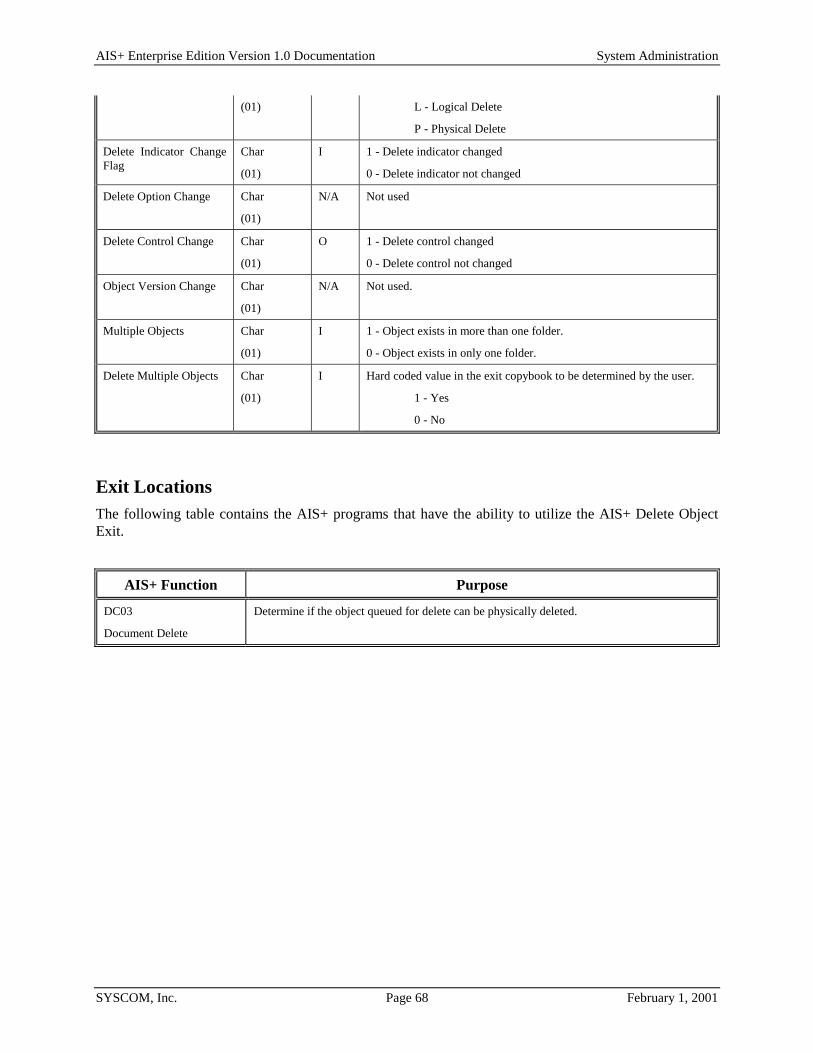
AIS+ Enterprise Edition Version 1.0 Documentation System Administration
SYSCOM, Inc. Page 68 February 1, 2001
(01)
L - Logical Delete
P - Physical Delete
Delete Indicator Change Flag
Char
(01)
I 1 - Delete indicator changed
0 - Delete indicator not changed
Delete Option Change Char
(01)
N/A Not used
Delete Control Change Char
(01)
O 1 - Delete control changed
0 - Delete control not changed
Object Version Change Char
(01)
N/A Not used.
Multiple Objects Char
(01)
I 1 - Object exists in more than one folder.
0 - Object exists in only one folder.
Delete Multiple Objects Char
(01)
I Hard coded value in the exit copybook to be determined by the user.
1 - Yes
0 - No
Exit Locations The following table contains the AIS+ programs that have the ability to utilize the AIS+ Delete Object Exit.
AIS+ Function Purpose
DC03
Document Delete
Determine if the object queued for delete can be physically deleted.
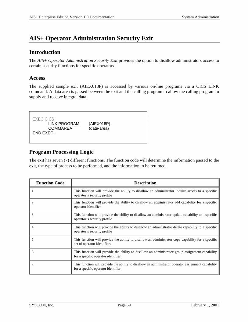
AIS+ Enterprise Edition Version 1.0 Documentation System Administration
SYSCOM, Inc. Page 69 February 1, 2001
AIS+ Operator Administration Security Exit
Introduction The AIS+ Operator Administration Security Exit provides the option to disallow administrators access to certain security functions for specific operators.
Access The supplied sample exit (AIEX018P) is accessed by various on-line programs via a CICS LINK command. A data area is passed between the exit and the calling program to allow the calling program to supply and receive integral data.
Program Processing Logic The exit has seven (7) different functions. The function code will determine the information passed to the exit, the type of process to be performed, and the information to be returned.
Function Code Description
1 This function will provide the ability to disallow an administrator inquire access to a specific operator’s security profile
2 This function will provide the ability to disallow an administrator add capability for a specific operator Identifier
3 This function will provide the ability to disallow an administrator update capability to a specific operator’s security profile
4 This function will provide the ability to disallow an administrator delete capability to a specific operator’s security profile
5 This function will provide the ability to disallow an administrator copy capability for a specific set of operator Identifiers
6 This function will provide the ability to disallow an administrator group assignment capability for a specific operator identifier
7 This function will provide the ability to disallow an administrator operator assignment capability for a specific operator identifier
EXEC CICS LINK PROGRAM (AIEX018P) COMMAREA (data-area) END EXEC.

AIS+ Enterprise Edition Version 1.0 Documentation System Administration
SYSCOM, Inc. Page 70 February 1, 2001
When the exit returns control to the calling program, it will also return a return code and a message code. The return code indicates what action the calling program should take as a result of the exit. The following values are outlined in the chart below.
Return Code Implication 0 Administrator has access to perform function for operator Identifier entered.
12 Administrator does not have access to perform function for operator Identifier entered. Message Code returned from exit will be displayed on screen.
Parameter List Structure The table below defines the format and the usage of the fields passed to the Operator Administration Security Exit. The actual parameters for the exit are contained in the COBOL copybook AILOPADM.
Parameter Name Format I/O Description
Application ID Bin
(02)
I This code tells the exit which application is active.
Function Code Char
(02)
I This indicates to the exit what function in AIS+ called the exit.
Return Code Num
(02)
O Returns a value of 0, or 12. This tells the calling program what action to take.
Message Code
Char
(08)
O This message code will be used to retrieve message to be displayed on screen. If return code 12 is returned by the exit, a value must be in this field.
User ID Char
(08)
I The user ID of the administrator performing the function being passed.
User Security Class Char
(02)
I The security class of the administrator performing the function being passed.
Modify User ID Char
(08)
I The user ID of the operator which is being manipulated.
Modify User Security Class
Char
(02)
I The security class of the operator which is being manipulated.
Copy From User ID Char
(08)
I The user ID of the operator whose information is being copied. Only used for Function code ‘5’.
Copy From User Security Class
Char
(02)
I The security class of the operator whose information is being copied. Only used for Function code ‘5’.

AIS+ Enterprise Edition Version 1.0 Documentation System Administration
SYSCOM, Inc. Page 71 February 1, 2001
Exit Locations The following table contains the AIS+ programs that have the ability to utilize the AIS+ Operator Administration Security Exit.
AIS+ Function Purpose
SA01
Operator Profile Inquire
Determine if administrator has access to inquire on operator Identifier entered.
SA01
Operator Profile Add
Determine if administrator has access to add operator Identifier entered.
SA01
Operator Profile Update
Determine if administrator has access to update operator Identifier entered.
SA01
Operator Profile Delete
Determine if administrator has access to delete operator Identifier entered.
SA02
Operator Assignment
Determine if administrator has access operator assignment for operator Identifier entered.
SA06
Operator Copy
Determine if administrator has access to copy from operator identifier enter to operator Identifier entered.
SA14
Group Assignment
Determine if administrator has access to group assignment for operator Identifier entered.

AIS+ Enterprise Edition Version 1.0 Documentation System Administration
SYSCOM, Inc. Page 72 February 1, 2001
AIS+ Line of Business Integration
Introduction The AIS+ Line of Business(L-O-B) Integration provides the mechanism to access the AIS+ Image System from other applications.
Access The name of the L-O-B transaction is AIST and the program name is AILB001P. The transaction is started from another application and is not executable by an operator.
The LOB application must issue the following command to invoke the AIS+ Sign-on transaction, the Sign-off transaction, the Print transaction and the View transaction:
EXEC CICS START TRANSID ('AIST') FROM (AIST-PARMS-COMMAREA) LENGTH (LENGTH OF AIST-PARMS-COMMAREA) SYSID (AIS-SYS-ID) END-EXEC
The LOB application must issue the following command to invoke all other AIS+ transactions, except for the Sign-on transaction, the Sign-off transaction, the Print transaction and the View transaction:
EXEC CICS START TRANSID ('AIST') FROM (AIST-PARMS-COMMAREA) LENGTH (LENGTH OF AIST-PARMS-COMMAREA) TERMID (EIBTRMID) SYSID (AIS-SYS-ID) END-EXEC
The format of the passed common area above is: 01 AIST-PARMS-COMMAREA. 05 AIST-TRANS-AREA. 10 AIST-TRANS-CODE PIC X(04). 10 FILLER PIC X(01) VALUE SPACES. 10 AIST-TRANS-PARMLIST PIC X(208). 10 FILLER PIC X(01) VALUE SPACES. 10 AIST-TRANS-TERMINAL-ID PIC X(04). 05 AIST-LOB-RET-AREA. 10 AIST-LOB-TRANS-CODE PIC X(08). 10 AIST-LOB-PARMLIST PIC X(20). 10 AIST-RET-SYS-ID PIC X(08).
Where; AIST-TRANS-CODE = AIS+ transaction that this LOB program should start AIST-TRANS-PARMLIST = Parameters being passed to the above AIS+ transaction. In most cases, this
data is in the same format as the FASTPATH command entered from a blank CICS screen. See note below for details.

AIS+ Enterprise Edition Version 1.0 Documentation System Administration
SYSCOM, Inc. Page 73 February 1, 2001
AIST-TRANS-TERMINAL-ID = The value in the EIBTRMID of the CICS session, where the LOB application program is running. This is a required entry, when the AIS+ Sign-on, Sign-off, Print or View transaction is invoked.
AIST-LOB-TRANS-CODE = The transaction to be started from AIS+ when the operator exits AIS. AIST-LOB-PARMLIST = Data to be passed back to the Line of Business transaction. AIST-RET-SYS-ID = System identifier where the LOB transaction resides. NOTE! A) AIS=TRANS_PARMLIST format updates. AISEE V1.0 includes an enhancement in the LOB integration that expanded the AIST-TRANS-PARMLIST
from 88 to 208 bytes to allow passing folder secondary indices. This change affected the DC06, FD01, FD02 and FD06 AIS+ transactions. Hence the parameters passed for these AIS+ transactions is as follows:
Document Index and Scan: DC06/FOLDERTYPE/FORMNAME/TAB-DESCRIPTION/FOLDERKEY/SECONDARY-INDEX1/SECONDARY-INDEX2/SECONDARY-INDEX3 Note: Secondary Index values 1, 2 & 3 are optional
Folder Addition (FD01):
FD01/FOLDERTYPE/FOLDERID/SECONDARY-INDEX1/SECONDARY-INDEX2/SECONDARY-INDEX3 Note: Secondary Index values 1, 2 & 3 are optional
Folder List by Folder Type:
FD02/FOLDERTYPE/SECONDARY-INDEX1/SECONDARY-INDEX2/SECONDARY-INDEX3 Note: At least one Secondary Index value is required
Folder Update:
FD06/OLD-FOLDERID/NEW-FOLDERTYPE/NEW-FOLDERID/SECONDARY-INDEX1/SECONDARY-INDEX2/SECONDARY-INDEX3 Note: Old-Folderid is required, all other parameters are optional
B) Usage Notes:
1. All required and optional parameters must be delimited by ‘,’ or ‘/’. The base AIS+ LOB code allows for ‘,’ or ‘/’ or space to be used as delimiter. In this modified version of the AIS+ LOB code, a space SHOULD NOT be used as a delimiter. Dropping the use of space as a delimiter enables you to pass parameters with imbedded blanks. For example, you may want to pass Primary Name field in ‘last-name middle-initial first-name’ format as one of the folder secondary indices.
2. To skip an optional parameter, put a delimiter in its place. Examples:
a) To pass only secondary-index-value2 for Folder List by Folder Type function (FD02), your LOB application must pass:
FOLDER-TYPE//SECONDARY-INDEX2
b) To pass only secondary-index-value3 for Folder List by Folder Type function (FD02), your LOB application must pass:
FOLDER-TYPE///SECONDARY-INDEX3

AIS+ Enterprise Edition Version 1.0 Documentation System Administration
SYSCOM, Inc. Page 74 February 1, 2001
c) To pass only the required parameters for Folder Add function (FD01), your LOB application must pass:
FOLDER-TYPE/FOLDERID
d) To pass the required parameters and the optional parameter secondary-index-value3 for the Folder Add function (FD01), your LOB application must pass:
FOLDER-TYPE/FOLDERID///SECONDARY-INDEX3
e) To pass the required parameters and all optional parameters for the Folder Add function (FD01), your LOB application must pass:
FOLDER-TYPE/NEW FOLDERID/SECONDARY INDEX1/SECONDARY INDEX2/SECONDARY INDEX3
Note the imbedded blanks in folder-id and secondary index parameters.
Program Processing Logic
Transaction Overview: When the transaction is started from the Line of Business Application, it receives the data passed in from the calling transaction. A check is made to validate that the AIS+ Sign-on function has occurred from the terminal in use. If not, a return code of '12' and a message code is put into the return area, and the LOB transaction is started. If the terminal has a valid AIS+ Sign-on associated with it, a temporary storage record is created to include all pertinent return transaction information for the LOB application. The program formats the passed data area and transfers control to the AIS+ application.
When the transaction is started from AIS+, the temporary storage queue created above is used to retrieve the LOB transaction area. The LOB transaction area is formatted and a 'START' command is issued to start the Line of Business (LOB) application.
The return area will be formatted as follows: 01 AIST-RETURN-PARMLIST.
05 AIST-RETURN-LOB-PARMS PIC X(20). 05 AIST-RETURN-MSG-CODE PIC X(08). 05 AIST-RETURN-CODE PIC 9(02).
where AIST-RETURN-LOB-PARMS is the data area passed into AIS+ from the line of business (AIST-LOB-PARMLIST in AIST-PARMS-COMMAREA), AIST-RETURN-MSG-CODE is the AIS+ message code, and AIST-RETURN-CODE is the return code of the call to AIS+. The return code may have the following values:
Return Code Implication
0 Processing completed successfully
12 Processing unsuccessful
16 Serious database or processing error
The line of business transaction will have to be coded to handle the return area above as well as the three processing conditions.
Note:

AIS+ Enterprise Edition Version 1.0 Documentation System Administration
SYSCOM, Inc. Page 75 February 1, 2001
In case of the Sign-on, Sign-off, Print and View transactions, when the AIS+ LOB transaction (AIST) is completed, it does not START the Line of Business application, but issues a CICS RETURN with no data returned. If there are any errors encountered, an entry is made to the EYPTELOG table. The return code can be found in the RETCODE column of the EYPTELOG table, and any error message can be found in the ERRDATA column ot the EYPTELOG table.

AIS+ Enterprise Edition Version 1.0 Documentation System Administration
SYSCOM, Inc. Page 76 February 1, 2001
Requirements for LOB Transaction: Modify any existing LOB code to start the AIS+ transaction(AIST). The format of the start command and the data passed to AIS+ are in the above sections. In addition, the data returned to the LOB application is also described above. Any executable transaction in the AIS+ system may be executed via this interface, including the sign-on and sign-off transactions. The sign-on transaction will be required prior to executing any other transactions in AIS+ through the LOB interface.

AIS+ Enterprise Edition Version 1.0 Documentation System Administration
SYSCOM, Inc. Page 77 February 1, 2001
AIS+ Line of Business Display/Print Integration
Introduction The AIS+ Line of Business (LOB) Integration provides the mechanism to access the AIS+ Image System from other applications. (see previous section) The Display/Print Integration utilizes the existing LOB integration to allow customers to display and/or print objects from within their Line of Business applications. The objects will be chosen by folder, and can be further delimited by form, tab, and/or a range of receive dates.
Access The access required to utilize the Display and Print capabilities is similar to that of normal Line of Business operations, mentioned in the preceding section. Rather than placing a transaction ID in the AIST-TRANS-CODE, enter a value of "LOBP" for printing, or "LOBV" for displaying objects. Further, any parameters used to specify which documents to process should be placed within the AIST-TRANS-PARMLIST. The layout of this data area follows:
01 AIST-PARMS-COMMAREA. 05 AIST-TRANS-AREA.
10 AIST-TRANS-CODE PIC X(04). 10 FILLER PIC X(01) VALUE ' '. 10 AIST-TRANS-PARMLIST. 15 WS-LB02-FOLDER-ID PIC X(26) VALUE SPACES. 15 WS-LB02-FORM-NAME PIC X(16) VALUE SPACES. 15 WS-LB02-START-DATE PIC X(10) VALUE SPACES. 15 WS-LB02-END-DATE PIC X(10) VALUE SPACES. 15 WS-LB02-TAB-DESC PIC X(16) VALUE SPACES. 15 WS-LB02-FUNCTION PIC X(01) VALUE SPACES. 15 WS-LB02-PRINTER-ID PIC X(08) VALUE SPACES. 15 FILLER PIC X(01) VALUE SPACES. 10 FILLER PIC X(01) VALUE SPACES. 10 AIST-TRANS-TERMINAL-ID PIC X(04).
05 AIST-LOB-RET-AREA. 10 AIST-LOB-TRANS-CODE PIC X(08). 10 AIST-LOB-PARMLIST PIC X(20). 10 AIST-RET-SYS-ID PIC X(08).
Within each LOB program that will utilize this functionality, programmatically place the value of the Folder Id whose documents are to be processed within the field WS-LB02-FOLDER-ID. This value is required and can span up to twenty-six (26) characters. The next field, WS-LB02-FORM-NAME, is optional. If utilized, this field should contain the Form Name of documents within that folder which should be processed. The next two (2) fields, WS-LB02-START-DATE and WS-LB02-END-DATE, work in unison. Together, these fields delimit which documents to process based upon a range that is applied against an object's Receive Date. Only those objects whose Receive Date falls on or within this range will be allowed to be processed. The use of these two (2) fields is also optional. If the date range is not going to be utilized, be sure that the corresponding fields contain spaces. The field WS-LB02-TAB-DESC is also optional. This field will delimit which objects to process based upon their Tab Code value. The WS-LB02-FUNCTION field is used by the source modules and should not be modified. Lastly, the field WS-LB02_PRINTER-ID is also optional. When used, this field can determine which printer to use when printing the document(s). If this field is left blank, the default printer defined in the OMDPRTID of

AIS+ Enterprise Edition Version 1.0 Documentation System Administration
SYSCOM, Inc. Page 78 February 1, 2001
the IDWKCFTB table for that terminal will be used. Optionally enter either a valid printer-id to override the default, or enter a value of "A". By placing a value of "A" in this field, the alternate printer that is defined in the OMDALTPR column of the Workstation Configuration table (IDWKCFTB) for the applicable terminal will be used.
The value in the EIBTRMID field must be passed in the AIST-TRANS-TERMINAL-ID field.
Any documents that pass all edits up to this point will then be checked for security access. For a document to either display or print, the user requesting the action must have a security level high enough to access the document, and must also have access to that group which the document belongs. Such documents that do not meet this criteria are simply passed over, as if they do not exist.
Program Processing Logic
Transaction Overview: When the transaction (AIST) is started from the Line of Business Application, it receives the data passed in from the LOB program that started it. Upon entry, a check is made to validate that the AIS+ Sign-on function has occurred from the terminal in use. If it has not occurred, a return code of '12' and an AIS+ message code are placed into the return area, and the Return LOB transaction is started. If the terminal has a valid AIS+ Sign-on associated with it, a temporary storage record is created to include all pertinent return transaction information for the LOB application. At this point the new L.O.B. Display / Print program is executed. This program will validate all information that was passed. If any errors arise, an entry is made to the EYPTELOG table. The appropriate Return Code is stored in the RETCODE column of the EYPTELOG table and the associated error message is stored in the ERRDATA column of the EYPTELOG table. An interpretation of the return codes is as follows:
Return Code Implication
00 Display/Print processing completed successfully.
04 Display/Print processing completed successfully. However, either no documents met the criteria, or on a Display request, the number of valid documents exceeded the maximum of ninety-nine (99) which are allowable. In this second scenario, only the first ninety-nine (99) will be displayed.
12 Processing unsuccessful. Some of the input values were not valid.
16 Serious database or processing error. When this occurs, a detailed entry will be placed into a Temporary Storage queue named "LB02ERRQ". Use the CICS command, CEBR, to browse the queue for a detailed description of the problem. See TSQ layout below.
The layout of the Temporary Storage queue "LB02ERRQ" is outlined below. Each of the values are separated by a filler of three (3) bytes for ease of reading.
Paragraph name where the error occurred. Length of 20 bytes. Table name upon which the error occurred. Length of 8 bytes. (if applicable) The process that was trying to execute. Length of 8 bytes. The value of the SQL Code. Length of 5 bytes. (if applicable) The return code of the error. Length of 2 bytes. (usually 16) The Reason Code 1 value. Length of 4 bytes. (if applicable) The Reason Code 2 value. Length of 4 bytes. (if applicable)

AIS+ Enterprise Edition Version 1.0 Documentation System Administration
SYSCOM, Inc. Page 79 February 1, 2001
The line of business transaction will have to be coded to handle the return area below, as well as the above four (4) processing conditions. When the Print/View Line of Business transaction is completed, the control is passed back to the AIST transaction.

AIS+ Enterprise Edition Version 1.0 Documentation System Administration
SYSCOM, Inc. Page 80 February 1, 2001
Appendix A: CICS Transaction/Program List
Transaction Program Description
DC01 AIDC001P Document List
DC02 AIDC002P Document Copy/Move
DC03 AIDC003P Document Delete/Undelete
DC04 AIDC004P Document History
DC05 AIDC005P Document Modify
DC06 AIDC006P Document Index and Scan
DC07 AIDC007P Temporary ID Format
DC08 AIDC008P Scan Pending Display
FD01 AIFD001P Folder Addition
FD02 AIFD002P Folder List by Folder Type
FD03 AIFD003P Folder List by Folder ID
FD04 AIFD004P Folder List by Folder/Tab
FD05 AIFD005P Folder Deletion
FD06 AIFD006P Folder Update
HP01 AIHP001P Host Print
MN01 AIMN001P Application Menu
MN02 AIMN002P Main Menu
MN03 AIMN003P System Administration Menu
NT01 AINT001P Note List
NT02 AINT002P Note View
NT03 AINT003P Note Add
NT04 AINT004P Note Delete
NT05 AINT005P Note Move
RT01 AIRT001P Document Register and Route
RT02 AIRT002P Bad Transaction Error Logging
SA01 AISA001P Operator Profile
SA02 AISA002P Operator Assignment
SA03 AISA003P Form Profile
SA04 AISA004P Folder Profile
SA05 AISA005P Application Profile (Update 1)
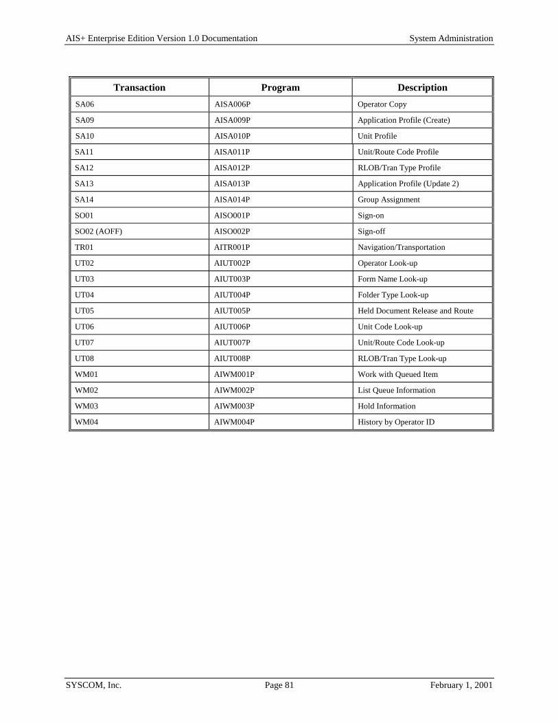
AIS+ Enterprise Edition Version 1.0 Documentation System Administration
SYSCOM, Inc. Page 81 February 1, 2001
Transaction Program Description SA06 AISA006P Operator Copy
SA09 AISA009P Application Profile (Create)
SA10 AISA010P Unit Profile
SA11 AISA011P Unit/Route Code Profile
SA12 AISA012P RLOB/Tran Type Profile
SA13 AISA013P Application Profile (Update 2)
SA14 AISA014P Group Assignment
SO01 AISO001P Sign-on
SO02 (AOFF) AISO002P Sign-off
TR01 AITR001P Navigation/Transportation
UT02 AIUT002P Operator Look-up
UT03 AIUT003P Form Name Look-up
UT04 AIUT004P Folder Type Look-up
UT05 AIUT005P Held Document Release and Route
UT06 AIUT006P Unit Code Look-up
UT07 AIUT007P Unit/Route Code Look-up
UT08 AIUT008P RLOB/Tran Type Look-up
WM01 AIWM001P Work with Queued Item
WM02 AIWM002P List Queue Information
WM03 AIWM003P Hold Information
WM04 AIWM004P History by Operator ID

AIS+ Enterprise Edition Version 1.0 Documentation System Administration
SYSCOM, Inc. Page 82 February 1, 2001
Appendix B: CICS User Exit/Program List At certain points during processing, the AIS+ system passes control to the AIS+ exits which can be enhanced by you. Enhancing the exits provides an additional means for you to customize an application to meet your end-user's needs.
The following table recaps which AIS+ function calls which exit and the purpose for calling the exit.
Customer Exit Locations and Options
User Exit Function Option Code
Purpose
AIEX001P
Customer Data
FD01
Folder Addition
0 Accepts or rejects access to the folder ID entered by the user. Modifies the folder ID of the folder to be created.
2 Provides customer-related information for display on the second line of the AIS+ Folder Addition screen and changes folder information.
FD04
Folder Tab List
0 Accepts or rejects access to the folder ID entered by the user. Modifies the folder ID of the folder to be displayed. Also provides customer-related information for display on the second line of the screen.
1 Provides customer-related information for display on the second line of the AIS+ Folder List by Folder/Tab screen.
FD05
Folder Delete
0 Accepts or rejects access to the folder ID entered by the user. Modifies the folder ID of the folder to be deleted. Also provides customer-related information for display on the second line of the screen.
1 Provides customer-related information for display on the second line of the AIS+ Folder Delete screen.
FD06
Folder Update
0 Accepts or rejects access to the folder ID entered by the user. Modifies the folder ID of the folder to be updated. Also provides customer-related information for display on the second line of the screen.
1 Provides customer-related information for display on the second line of the AIS+ Folder Update screen.
NT01
Note List
0 Accepts or rejects access to the folder ID entered by the user. Modifies the folder ID of the folder to be displayed. Also provides customer-related information for display on the second line of the screen.
1 Provides customer-related information for display on the second line of the AIS+ Note List screen.
NT03
Note Addition
0 Accepts or rejects access to the folder ID entered by the user. Modifies the folder ID of the folder to be updated. Also provides customer-related information for display on the second line of the screen.

AIS+ Enterprise Edition Version 1.0 Documentation System Administration
SYSCOM, Inc. Page 83 February 1, 2001
Customer Exit Locations and Options
User Exit Function Option Code
Purpose
1 Provides customer-related information for display on the second line of the AIS+ Note Addition screen.
DC01
Document List
0 Accepts or rejects access to the folder ID entered by the user. Modifies the folder ID of the folder to be displayed. Also provides customer-related information for display on the second line of the screen.
1 Provides customer-related information for display on the second line of the AIS+ Document List screen. Exit will also obtains the user parameter 1 and user parameter 2 fields to determine the unit code and route code.
DC02
Document Copy/Move
0 Accepts or rejects access to the folder ID entered by the user. Modifies the folder ID of the folder to be displayed.
2 The exit can change folder information if AIS+ is directed to create a folder.
DC04
Document History
1 Provides customer-related information for display on the second line of the AIS+ Document History screen.
DC05
Document Modify
1 Provides customer-related information for display on the second line of the AIS+ Document Modify screen.
DC05
Document Modify
(Route Document)
1 Provides the customer-related information for display on the second line of the AIS+ Document Modify screen. When rerouting a document this user exit will also be called to obtain the user parameter 1 and user parameter 2 fields to determine the unit code and route code.
DC06
Document Index and Scan
(Document Routed)
0 Accepts or rejects access to the folder ID entered by the user. Modifies the folder ID of the folder to be updated. Also provides customer-related information for display on the second line of the screen.
1 Provides the customer-related information for display on the second line of the AIS+ Document Index and Scan screen. When rerouting a document this user exit will also be called to obtain the user parameter 1 and user parameter 2 fields to determine the unit code and route code.
DC06
Document Index and Scan (Document Stored but not Routed)
3 Modifies any of the information for the document that is to be added. Provides the customer-related information for display on the second line of the AIS+ Document Index and Scan screen.
DC06
Document Index and Scan (Document Stored and Routed)
4 Provides the customer-related information for display on the AIS+ Document Index and Scan screen. Changes the document and routing information.

AIS+ Enterprise Edition Version 1.0 Documentation System Administration
SYSCOM, Inc. Page 84 February 1, 2001
Customer Exit Locations and Options
User Exit Function Option Code
Purpose
DC06
Document Index and Scan
5 This exit will direct AIS+ to create a folder if one does not exist.
DC08
Scan Pending Display
1 Provides the customer-related information for display on the second line of the AIS+ Document Index and Scan screen. When rerouting a document this user exit will also be called to obtain the user parameter 1 and user parameter 2 fields to determine the unit code and route code.
WM01
Work With Queued Items
1 Provides the customer-related information for display on the second line of the AIS+ Work With Queued Items screen. When rerouting a document this user exit will also be called to obtain the user parameter 1 and user parameter 2 fields to determine the unit code and route code.
WM02
Queue Information
0 If a folder ID is entered, the exit will accept or reject access to the folder ID. Also optionally, the exit modifies the folder ID of the folder to be displayed.
AIEX002P
Validate Data
FD01
Folder Addition
1 Accepts or rejects the data entered by the user before a new folder is created.
FD06
Folder Update
2 Accepts or rejects the data entered by the user for update.
DC02
Document Copy/Move
5 Accepts or rejects information about the document that is copied or moved.
DC05
Document Modify
(Update Document Info.)
4 Accepts or rejects information that is to be updated for a document.
DC05
Document Modify
(Move Pages)
3 Accepts or rejects information about the new document that is created as a result of moving pages from an existing document.
DC06
Document Index and Scan
1 Accepts or rejects data entered by the user before a new folder is created.
DC06
Document Index and Scan (Document Stored but not Routed)
3 Accepts or rejects information about the document.

AIS+ Enterprise Edition Version 1.0 Documentation System Administration
SYSCOM, Inc. Page 85 February 1, 2001
Customer Exit Locations and Options
User Exit Function Option Code
Purpose
DC06
Document Index and Scan (Document Stored and Routed)
5 Accepts or rejects information about the new document that is added and routed.
AIEX003P
Routing Exit
DC01
Document List
(Reroute)
None Changes the routing information of a document before placing the document in the routing queue.
DC01
Document List
(Send Work)
None Changes the routing information of a document before placing the document in the routing queue.
DC05
Document Modify
(Route Document)
None Changes the routing information of a document before placing the document in the routing queue.
DC06/RT01
Document Index and Scan
None Changes any of the routing information before placing the document in the routing queue. AIS+ calls the routing data exit after the document is scanned.
WM01
Work With Queued Items (Reroute)
None Changes the routing information of a document before placing the document in the routing queue.
AIEX004P
Storage Management
DCO5
Document Modify
(Move Pages)
None When moving pages from one folder to another, this exit is invoked to provide storage management parameters for the new document.
DC06
Document Index and Scan
None Provides the collection name and the storage management values of the document. AIS+ uses this information to store the document.
AIEX005P
Security Exit
SO01
Sign On
None Allows or disallows user to signon to AIS+. This exit can be used to verify ACF2 and RACF user authority. If exit allows sign-on, the Security exit program will check the AIS+ Operator Profile table to verify the user is a valid AIS+ user.
SO02
Sign Off
None Allows or disallows the user to sign off to AIS+.
AIEX013P
Event Format
DC01
Document List
None Provides ability to log events associated with document usage.
DC02
Document Copy/Move
None Provides ability to log events associated with document usage.

AIS+ Enterprise Edition Version 1.0 Documentation System Administration
SYSCOM, Inc. Page 86 February 1, 2001
Customer Exit Locations and Options
User Exit Function Option Code
Purpose
DC03
Document Delete/Undelete
None Provides ability to log events associated with document usage.
DC05
Document Modify
None Provides ability to log events associated with document usage.
DC06
Document Index & Scan
None Provides ability to log events associated with document usage.
RT01
Document Register & Route
None Provides ability to log events associated with document usage.
AIEX015P
Prefetch Exit
DC01
Document list
1 Allow or disallow view, print, or host print at the object level request.
FD02
Folder Index
3 Allow or disallow host point request at the folder level.
FD03
Folder ID
3 Allow or disallow host print request at the folder level
FD04
Folder Tab
2 Allow or disallow host print request at the folder tab level.
WM01 Work with Queued Items
1 Allow or disallow view print or host print request at the object level.
WM02 Queue List 1 Allow or disallow view request at the object level.
AIEX016P
Field Edit Exit
DC06
Document Index and Scan
None Allow editing of the secondary indexes based on the edit numbers, before the folder is created.
FD01
Folder Addition
None Allow editing of the secondary indexes based on the edit numbers, before the folder is created.
FD06
Folder Update
None Allow editing of the secondary indexes based on the edit numbers, before the folder information is updated.
AIEX017P
Delete Object Exit
DC03
Document Delete
1 Determine whether a document is to be deleted logically or physically.

AIS+ Enterprise Edition Version 1.0 Documentation System Administration
SYSCOM, Inc. Page 87 February 1, 2001
Customer Exit Locations and Options
User Exit Function Option Code
Purpose
AEIX018P SA01 1 Allow or disallow operator Inquiry.
2 Allow or disallow operator add.
3 Allow or disallow operator update.
4 Allow or disallow operator delete.
SA06 5 Allow or disallow operator copy.
SA02 7 Allow or disallow operator assignment.
SA14 6 Allow or disallow group assignment.
On-line Function Codes
Function Function Code
Add Folder 01
Update Folder Information 02
List Folders 04
Add Folder Note 11
List Folder Notes 12
Document History Display 33
Document Move 34
Document Copy 36
Add and Route Document
This function code is also used for the indexing workstation interface.
51
Add and Route Document.
The routing information changed.
52
Get Work 53
Reroute Document 57

AIS+ Enterprise Edition Version 1.0 Documentation System Administration
SYSCOM, Inc. Page 88 February 1, 2001
Appendix C: AIS+ DB2 Architecture
AIS+ Database Information All AIS+ information is maintained in a series of IBM DB2 tables. Each table resides in its own tablespace and, in turn, all tablespaces reside under one database.
There are seventeen (17) AIS+ tables and five (5) views of FAF/API tables used by AIS+ EE software that aid in configuring and administering information utilized by the applications running within AIS+. These tables and views are in addition to the IBM FAF, IBM IODM, and IBM OAM DB2 tables used by the respective products. AIS+ supports the tablesets for the following IBM FAF tables: EYPTOBJT, EYPTFOLD, EYPTSNDX, EYPTNOTE, EYPTVERS, EYPTEVNT AND EYPTONAM. Please refer to the appropriate IBM product manual for further information relative to the IBM DB2 tables.
Description Table Name
Profile for each application used within AIS+. AISAPPL
Collection name assignment per form used by application. AISCOLL
Profile for each form used by application. AISDCMT
Log maintained for document and folder deletions. AISDLOG
Delete reason codes used when deleting a document or folder. AISDRSN
Default tab within a folder used by document when initially entering application. AISDTAB
Profile for each folder used by application. AISFLDR
Operator Group Assignments AISGOPR
Profile for each group used by the application. AISGRUP
All messages used within application. AISMSGS
Operator queue assignments. AISOPAS view of EYPTWEAS
Profile for each operator using an application. AISOPPF
Host print detail of each object requested for print AISPRTDT
Host print status for each request made by an operator AISPRTRQ
Error recovery/restart table. AISRCOV
Routing-line-of-business/transaction type routing information. AISRLTT view of EYPTWRTT
Operator statistics for each operator within a unit AISSTATS
Tabs associated for a folder type. AISTABS
CICS transactions for AIS+. AISTRAN
Units used in routing. AISUNIT view of EYPTWUNT
Unit/Route Code combinations used in routing. AISUNRC view of EYPTWURC
Work detail table. AISWORK view of EYPTWDET

AIS+ Enterprise Edition Version 1.0 Documentation System Administration
SYSCOM, Inc. Page 89 February 1, 2001
The following pages will present information regarding the DB2 architecture associated with AIS+.
AIS+ DB2 Plan X-Ref The following information displays cross reference association of the AIS+ DB2 plans and their AIS+ members, and by individual members, the plans they exist in.
Plan Member
DC01 DC01 DC02 DC03 DC04 DC05 DC08 HP01 WM01 WM02
DC02 DC01 DC02 DC03 DC04 DC05 HP01 WM01 WM02
DC03 DC01 DC02 DC03 DC04 DC05 HP01 WM01
DC04 DC01 DC02 DC03 DC04 DC05 HP01 WM01 WM02
DC05 DC01 DC02 DC03 DC04 DC05 HP01 WM01 WM02
DC06 DC06
DC08 DC01 DC02 DC03 DC04 DC05 DC08 HP01 WM01 WM02
FD01 FD01
FD02 FD02 HP01
FD03 FD03 HP01
FD04 FD04 HP01
FD05 FD05 HP01
FD06 FD06
HP01 DC01 DC02 DC03 DC04 DC05 FD02 FD03 FD04 HP01 WM01
LB01 LB01 LB02
LB02 LB02
MN01 MN01
MN02 MN02 UT04 UT06
MN03 MN03 SA10 SA11 SA12 UT02 UT03 UT04 UT06 UT07 UT08
NT01 NT01 NT02 NT04 NT05
NT02 NT02 NT01
NT03 NT03
NT04 NT04
NT05 NT05
RT01 RT01
RT02 RT02
SA01 SA01
SA02 SA02
SA03 SA03
SA04 SA04

AIS+ Enterprise Edition Version 1.0 Documentation System Administration
SYSCOM, Inc. Page 90 February 1, 2001
Plan Member
SA05 SA05
SA06 SA06

AIS+ Enterprise Edition Version 1.0 Documentation System Administration
SYSCOM, Inc. Page 91 February 1, 2001
Plan Member
SA09 SA09
SA10 SA10
SA11 SA11
SA12 SA12
SA13 SA13
SA14 SA14
SO01 MN01 SO01
TR01 TR01
UT02 UT02
UT03 UT03
UT04 UT04
UT05 UT05
UT06 UT06
UT07 UT07
UT08 UT08
WM01 DC02 DC03 DC04 DC05 HP01 WM01
WM02 DC01 DC02 DC04 DC05 WM02
WM03 WM03
WM04 WM04

AIS+ Enterprise Edition Version 1.0 Documentation System Administration
SYSCOM, Inc. Page 92 February 1, 2001
Member Plan DC01 DC01 DC02 DC03 DC04 DC05 DC08 HP01 WM02
DC02 DC01 DC02 DC03 DC04 DC05 DC08 HP01 WM01 WM02
DC03 DC01 DC02 DC03 DC04 DC05 DC08 HP01 WM01
DC04 DC01 DC02 DC03 DC04 DC05 DC08 HP01 WM01 WM02
DC05 DC01 DC02 DC03 DC04 DC05 DC08 HP01 WM01 WM02
DC06 DC06
DC08 DC01 DC08
FD01 FD01
FD02 FD02 HP01
FD03 FD03 HP01
FD04 FD04 HP01
FD05 FD05
FD06 FD06
HP01 DC01 DC02 DC03 DC04 DC05 FD02 FD03 FD04 HP01 WM01
MN01 MN01 SO01
MN02 MN02
MN03 MN03
NT01 NT01 NT05
NT02 NT01 NT02
NT03 NT03
NT04 NT01 NT04
NT05 NT01 NT05
RT01 RT01
RT02 RT02
SA01 SA01
SA02 SA02
SA03 SA03
SA04 SA04
SA05 SA05
SA06 SA06
SA09 SA09

AIS+ Enterprise Edition Version 1.0 Documentation System Administration
SYSCOM, Inc. Page 93 February 1, 2001
Member Plan
SA10 MN03 SA10
SA11 MN03 SA11
SA12 MN03 SA12
SA13 SA13
SA14 SA14
SO01 SO01
TR01 TR01
UT02 MN03 UT02
UT03 MN03 UT03
UT04 MN02 MN03 UT04
UT05 UT05
UT06 MN02 MN03 UT06
UT07 MN03 UT07
UT08 MN03 UT08
WM01 DC02 DC03 DC04 DC05 HP01 WM01
WM02 DC02 DC04 DC05 WM02
WM03 WM03
WM04 WM04

AIS+ Enterprise Edition Version 1.0 Documentation System Administration
SYSCOM, Inc. Page 94 February 1, 2001
AIS+ DB2 Table X-Ref The following information displays cross reference usage of the AIS+ DB2 tables by program, and by program, table usage.
AIS+ Table Programs Using As Read-Only Programs Performing Modifications
AISAPPL DC02 DC03 DC06 MN01 RT01 SA01 SA02 SA06 SO01 SA05 SA09 SA13
AISCOLL DC05 DC06 SA03
AISDCMT DC01 DC05 DC06 UT03 RT01 WM02 SA03
AISDLOG DC02 DC03 FD05
AISDRSN DC02 DC03 FD05
AISDTAB DC05 DC06 SA03
AISFLDR DC01 DC04 DC05 DC06 FD01 FD02 FD03 FD04 FD05 FD06 HP01 NT01 NT05 SA01 SA03 SA06 UT04 WM01 WM02
SA04
AISGOPR DC01 WM01 WM02 SA01 SA06 SA09 SA14
AISGRUP DC01 WM01 WM02 SA03 SA09 SA14
AISRCOV UT05
AISMSGS DC01 DC02 DC03 DC04 DC05 DC06 FD01 FD02 FD03 FD04 FD05 FD06 HP01 MN01 MN02 MN03 NT01 NT02 NT03 NT04 NT05 RT01 SA01 SA02 SA03 SA04 SA05 SA06 SA09 SA10 SA11 SA12 SA13 SA14 SO01 TR01 UT02 UT03 UT04 UT06 UT07 UT08 WM01 WM02 WM03 WM04
AISOPAS DC01 SA02 WM01 WM02
AISOPPF DC01 DC06 FD01 FD02 FD03 FD04 FD05 FD06 HP01 MN01 MN02 MN03 NT01 NT03 SA03 SA04 SA05 SA10 SA11 SA12 SA13 SA14 SO01 UT02 WM01 WM02 WM03 WM04
SA01 SA02 SA06 SA09
AISPRTDT HP01
AISPRTRQ HP01
AISRLTT DC01 DC05 DC06 RT01 SA03 UT08 WM01 SA12
AISTABS DC01 DC06 FD04 SA03 WM01 WM02 SA04
AISTRAN DC01 DC06 FD01 FD02 FD03 FD04 FD05 FD06 HP01 MN01 MN02 MN03 NT01 NT03 SA01 SA02 SA03 SA04 SA05 SA06 SA10 SA11 SA12 SA13 SA14 SO01 WM01 WM02 WM03 WM04
AISUNIT DC01 DC05 DC06 SA11 SA12 UT06 WM01 WM02 WM03 SA10
AISUNRC DC01 DC05 DC06 SA02 SA12 UT07 WM01 WM02 SA11
AISWORK DC01 DC04 SA02 WM03 DC02 DC03 DC05 RT01 UT05 WM01 WM02

AIS+ Enterprise Edition Version 1.0 Documentation System Administration
SYSCOM, Inc. Page 95 February 1, 2001
FAF Table Programs Using As Read-Only Programs Performing
Modifications
EYPTCOLL DC08 HP01 SA03
EYPTELOG RT01 RT02 UT05
EYPTEVNTxx DC04 WM04
EYPTFOLDxx DC01 DC06 FD02 FD03 NT05 WM02
EYPTMODI WM01
EYPTNOTExx FD02 FD03 FD04 NT01
EYPTONAMxx HP01
EYPTOBJTxx DC01 DC02 DC04 DC05 FD02 FD03 FD04 HP01 WM02 DC03 WM01
EYPTSCAN DC01 DC08
EYPTSNDXxx DC01 DC06 FD02 FD03 FD04 FD06
EYPTSPAC SA09
EYPTSYMB SA09
EYPTVERSxx DC01
IODM Table Programs Using As Read-Only Programs Performing
Modifications
IDFMSXTB SO01
IDWKCFTB SO01
SDSTCTTB DC08
OAM Table Programs Using As Read-Only
OAMMGT SA03
OAMSTO SA03
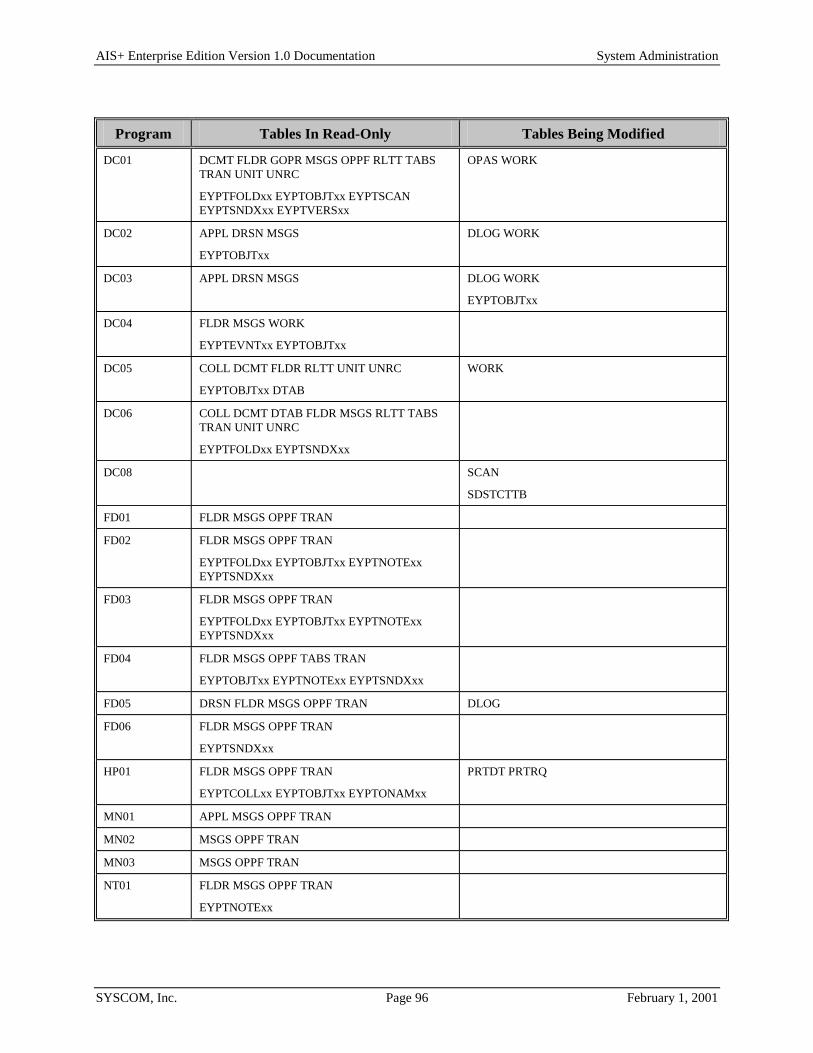
AIS+ Enterprise Edition Version 1.0 Documentation System Administration
SYSCOM, Inc. Page 96 February 1, 2001
Program Tables In Read-Only Tables Being Modified
DC01 DCMT FLDR GOPR MSGS OPPF RLTT TABS TRAN UNIT UNRC
EYPTFOLDxx EYPTOBJTxx EYPTSCAN EYPTSNDXxx EYPTVERSxx
OPAS WORK
DC02 APPL DRSN MSGS
EYPTOBJTxx
DLOG WORK
DC03 APPL DRSN MSGS DLOG WORK
EYPTOBJTxx
DC04 FLDR MSGS WORK
EYPTEVNTxx EYPTOBJTxx
DC05 COLL DCMT FLDR RLTT UNIT UNRC
EYPTOBJTxx DTAB
WORK
DC06 COLL DCMT DTAB FLDR MSGS RLTT TABS TRAN UNIT UNRC
EYPTFOLDxx EYPTSNDXxx
DC08 SCAN
SDSTCTTB
FD01 FLDR MSGS OPPF TRAN
FD02 FLDR MSGS OPPF TRAN
EYPTFOLDxx EYPTOBJTxx EYPTNOTExx EYPTSNDXxx
FD03 FLDR MSGS OPPF TRAN
EYPTFOLDxx EYPTOBJTxx EYPTNOTExx EYPTSNDXxx
FD04 FLDR MSGS OPPF TABS TRAN
EYPTOBJTxx EYPTNOTExx EYPTSNDXxx
FD05 DRSN FLDR MSGS OPPF TRAN DLOG
FD06 FLDR MSGS OPPF TRAN
EYPTSNDXxx
HP01 FLDR MSGS OPPF TRAN
EYPTCOLLxx EYPTOBJTxx EYPTONAMxx
PRTDT PRTRQ
MN01 APPL MSGS OPPF TRAN
MN02 MSGS OPPF TRAN
MN03 MSGS OPPF TRAN
NT01 FLDR MSGS OPPF TRAN
EYPTNOTExx

AIS+ Enterprise Edition Version 1.0 Documentation System Administration
SYSCOM, Inc. Page 97 February 1, 2001
Program Tables In Read-Only Tables Being Modified
NT02 MSGS
NT03 MSGS OPPF TRAN
NT04 MSGS
NT05 FLDR MSGS
EYPTFOLDxx
RT01 APPL DCMT MSGS RLTT WORK
EYPTELOG
RT02 EYPTELOG
SA01 APPL FLDR MSGS TRAN GOPR OPPF
SA02 APPL MSGS TRAN UNRC WORK OPAS OPPF
SA03 FLDR MSGS OPPF RLTT TABS TRAN
EYPTCOLL
OAMMGT OAMSTO
COLL DCMT DTAB GRUP
SA04 MSGS OPPF TRAN FLDR TABS
SA05 MSGS OPPF TRAN
OAMCOLL
APPL
SA06 APPL FLDR MSGS TRAN GOPR OPPF
SA09 MSGS
EYPTSYMB
OAMCOLL
APPL GOPR GRUP OPPF
EYPTSPAC
SA10 MSGS OPPF TRAN UNIT
SA11 OPPF MSGS TRAN UNIT UNRC
SA12 MSGS OPPF UNIT UNRC TRAN RLTT
SA13 MSGS OPPF TRAN APPL
SA14 MSGS OPPF TRAN GOPR GRUP
SO01 APPL MSGS OPPF TRAN
IDFMSXTB IDWKCFTB
TR01 MSGS
UT02 MSGS OPPF
UT03 DCMT MSGS
UT04 FLDR MSGS
UT05 RCOV WORK
EYPTELOG

AIS+ Enterprise Edition Version 1.0 Documentation System Administration
SYSCOM, Inc. Page 98 February 1, 2001
Program Tables In Read-Only Tables Being Modified
UT06 MSGS UNIT
UT07 MSGS UNRC
UT08 MSGS RLTT
WM01 FLDR GOPR MSGS OPPF RLTT TABS TRAN UNIT UNRC
OPAS WORK
EYPTMODI EYPTOBJTxx
WM02 DCMT FLDR GOPR MSGS OPPF TABS TRAN UNIT UNRC
EYPTFOLDxx EYPTOBJTxx
OPAS WORK
WM03 MSGS OPPF TRAN UNIT WORK
WM04 MSGS OPPF TRAN
EYPTEVNTxx

AIS+ Enterprise Edition Version 1.0 Documentation System Administration
SYSCOM, Inc. Page 99 February 1, 2001
AIS+ DB2 Space Requirements The space required for AIS+ is relatively small compared to the enormous space necessary to maintain the IBM FAF DB2 tables. This section is intended only to give a snapshot of a default base implementation. If your shop has requirements that differ from the assumptions, then you will need to adjust the sizes and free space utilization accordingly. But, for the most part, your application should easily fit within the guidelines provided.
Table Lgth Rows/ Page
% Free
Free Page
PRIQTY (PAGES)
SEC QTY
Contents Within Primary Quantity
AISAPPL 266 16 0 0 12 (3) 0 15 Application Profiles
AISCOLL 90 45 0 0 12 (3) 00 45 Collection/Form Combinations (Only used when a form has a specific collection name associated with it)
AISDCMT 146 28 0 0 12 (3) 0 28 Document Profiles (One profile per document type used)
AISDLOG 207 28 (22) 20 0 168 (42) 0 880 Entries
AISDRSN 29 127 0 0 12 (3) 0 127 Reasons (Only 54 needed per application)
AISDTAB 46 88 0 0 12 (3) 0 88 Document/Folder Tab Default Combinations (A document can only have one default tab)
AISFLDR 259 15 0 0 12 (3) 0 15 Folder Profiles (One profile per folder type used)
AISGOPR 20 114 10 10 20(5) 10 250 Operator Group Assignments.
AISGRUP 20 127 0 0 12(3) 0 127 Group Profiles.
AISMSGS 88 46 0 0 48 (12) 0 460 Messages (400 AIS+ & 60 User)
AISOPAS 31 127(101) 20 0 12 (3) 0 127 Operator Assignments
AISOPPF 109 42 (33) 20 0 48 (12) 0 330 Operator Profiles
AISPRTDT 179 23 (20) 10 10 2208 (552) 1104 10,000 Host Print Detail Entries
AISPRTRQ 271 15 (13) 10 0 620 (155) 310 2,000 Host Print Requests
AISRCOV 4055 1 0 0 48 (12) 0 10 Entries
AISRLTT 88 45 0 0 12 (3) 0 45 RLOB/Transaction Type Combinations
AISSTATS 100 36 10 0 5508(1127) 2754 Acitvity Statistics for 50,000 Operator/Unit combinations.

AIS+ Enterprise Edition Version 1.0 Documentation System Administration
SYSCOM, Inc. Page 100 February 1, 2001
Table Lgth Rows/ Page
% Free
Free Page
PRIQTY (PAGES)
SEC QTY
Contents Within Primary Quantity
AISTABS 34 119 0 0 12 (3) 0 119 Folder Tabs (A folder can have multiple tabs)
AISTRAN 19 127 0 0 12 (3) 0 127 CICS Transaction IDs (AIS+ currently only uses about 50 per application)
AISUNIT 42 97 0 0 12 (3) 0 97 Routing Units
AISUNRC 98 41 0 0 12 (3) 0 41 Routing Queues (Routing Unit/Routing Code Combinations)
AISWORK 210 21 (16) 20 5 3608
(902)
1804 12,000 Entries
Index Key Lgth
Rows Leaf Page
Rows Non- Leaf
% Free
Free Page
Sub- page
PRIQTY (PAGES)
SECQTY
Contents Within Primary Quantity
AISAPPL 2 673 449 0 0 N/A 12 (1) 0 15 Application Profiles
AISCOLL 20 168 176 0 0 N/A 12 (1) 0 45 Collection/Form Combinations (Only used when a form has a specific collection name associated with it)
AISDCMT 4
18
506
184
579
193
0
0
0
0
N/A 12 (1)
12 (1)
0
0
28 Document Profiles (One profile per document type used)
AISDLOG 41 64 74 20 0 N/A 68 (15) 0 880 Entries
AISDRSN 5 450 506 0 0 N/A 12 (1) 0 127 Reasons (Only 54 needed per application)
AISDTAB 20 168 176 0 0 N/A 12 (1) 0 88 Document/Folder Tab Default Combinations (A document can only have one default tab)
AISFLDR 4
4
506
506
579
579
0
0
0
0
N/A 12 (1)
12 (1)
0
0
15 Folder Profiles (One profile per folder type used)
AISGOPR 12
10
227
302
243
281
10
10
10
10
N/A 20
16
0
0
250 Operator Group Assignments

AIS+ Enterprise Edition Version 1.0 Documentation System Administration
SYSCOM, Inc. Page 101 February 1, 2001
Index Key Lgth
Rows Leaf Page
Rows Non- Leaf
% Free
Free Page
Sub- page
PRIQTY (PAGES)
SECQTY
Contents Within
Primary Quantity
AISGRUP 4 506 571 10 10 N/A 12 0 127 Group Profiles
AISMSGS 8 337 368 0 0 N/A 20 (3) 0 460 Messages (400 AIS+ & 60 User)
AISOPAS 20
22
128
116
141
130
20
20
0
0
N/A 12 (1)
12 (1)
0
0
127 Operator Assignments
AISOPPF 10 260 281 10 0 N/A 20 (3) 0 330 Operator Profiles
AISPRTDT 18 160 174 10 0 N/A 268 (65) 134 10,000 Host Print Detail Entries
AISPRTRQ 18 160 174 10 0 N/A 68 (15) 34 2,000 Host Print Requests
AISRCOV 24 144 150 0 0 N/A 12 (1) 0 10 Entries
AISRLTT 18 184 193 0 0 N/A 12 (1) 0 45 RLOB/Transaction Type Combinations
AISSTATS 21 144 150 10 0 N/A 1408(352) 704 50,000 entries
AISTABS 6
6
405
405
450
450
0
0
0
0
N/A 12 (1)
12 (1)
0
0
119 Folder Tabs (A folder can have multiple tabs)
AISTRAN 6
6
405
405
450
450
0
0
0
0
N/A 12 (1)
12 (1)
0
0
127 CICS Transaction IDs (AIS+ currently only uses about 50 per application)
AISUNIT 12 253 270 0 0 N/A 12 (1) 0 97 Routing Units
AISUNRC 12 253 270 0 0 N/A 12 (1) 0 41 Routing Queues (Routing Unit/Routing Code Combinations)
AISWORK 26
20
33
100
128
20
111
141
23
20
20
80
0
0
0
N/A 500(123)
388(94)
2528(630)
250
194
1264
12,000 Entries

AIS+ Enterprise Edition Version 1.0 Documentation System Administration
SYSCOM, Inc. Page 102 February 1, 2001
AISAPPL - Application Profile Each application that will function within the AIS+ software must have an entry within the AIS+ AISAPPL table. An entry represents the characteristics, or profile, the application will be governed by while executing under AIS+.
The initial propagation of this table is accomplished through the use of the AIS+ Initial Application Profile Creation function (AIS+ EE System Administration Manual), and can be modified using either the AIS+ Application Profile (1) or the AIS+ Application Profile (2) functions (AIS+ EE User Reference Manual).
The following table contains the naming conventions used for the AIS+ Application Profile table.
DB2 Component AIS+ Supplied Name Your Company Naming Convention
Storage Group N/A
Database N/A
Tablespace AISTSAP
Table AISAPPL
Index AISIXAP1
Insertions and modifications to the table are extremely infrequent. A single unique index is supplied, but not required, that uses the application ID in ascending order.
Each AISAPPL entry has a length of 266 bytes, 258 bytes of data and 8 bytes for the DB2 header. Each index entry has a length of 2 bytes.
AISAPPL utilizes a simple single tablespace. Since this table is rarely updated, the locking mechanism should be set to use the "tablespace" though most shops will utilize "any". Again, since insertion is rare, both percent free and free pages should both be set to zero (0). There is no special requirement to have the table reside in any special bufferpool. The data does not need to be erased when the table is dropped. This table is used frequently by the application, so the tablespace should not be closed each time it is used.

AIS+ Enterprise Edition Version 1.0 Documentation System Administration
SYSCOM, Inc. Page 103 February 1, 2001
The below information utilizes the space calculations as prescribed in the IBM DB2 Installation Guide V6.1, Section 2.2.2 DASD Storage for User Data. The AISAPPL table space calculation is as follows: usable page size = (page size - 22) * ((100 - pctfree)/100) records per page = FLOOR(usable page size/(record size + overhead)) pages used = 2 + CEILING(number of rows/records per page) total pages = FLOOR(pages used * ((1 + freepage)/freepage) estimated kilobytes = total pages * 4
where: pages size = 4k pctfree = 0 data size = 258 overhead = 8 freepage = 0
usable page size = (4096 - 22) * ((100 - 0) / 100) = 4074 records per page = FLOOR(4074 / (258 + 8)) = 15
A single data page can carry a maximum of 15 application rows. Since this is more than enough to get started, we will use 15 as the "number of rows" in calculating space. Also note that when "freepage" is zero (0), the total pages is equal to the pages used. pages used = 2 + CEILING(15 / 15) = 3 total pages = FLOOR(3 * ((1 + 0) / 0) = 3 est. kilobytes = 3 * 4 = 12
Though an index is really not required for a single page data space, the following calculation illustrates the size required if used.
available space = (100 - pctfree) / 100 entries per leaf page = FLOOR(available space * 4038 / (key length + 4)) entries per non-leaf page = FLOOR(MAX(90, (available space * 4046)) / (key length + 7)) number of leaf pages = CEILING(number of table rows / entries per leaf number of non-leaf pages = CEILING(number of leaf pages / entries per non-leaf page total index pages = number of leaf pages + number of non-leaf pages estimated kilobytes = 4 * (total index pages + 2)
where: pctfree= 0 key length = 2 available space = (100 - 0) / 100 = 1 entries per leaf page = FLOOR(1 * 4038 / (2 + 4)) = 673 entries per non-leaf page = FLOOR(MAX(90, (1 * 4046)) / (2 + 7)) = 449
number of leaf pages = CEILING(15 / 673) = 1 number of non-leaf pages = CEILING(1 / 449) = 0 None used when leaf page = 1 total index pages = 1 + 0 = 1 estimated kilobytes = 4 * (1 + 2) = 12
This estimated index size will allow for an approximate 673 applications.

AIS+ Enterprise Edition Version 1.0 Documentation System Administration
SYSCOM, Inc. Page 104 February 1, 2001
The following tables reflect the aforementioned DB2 options required to build AIS+ AISAPPL.
Tablespace DDL Option Value Description
SEGSIZE N/A Simple tablespace does not use segments.
NUMPARTS N/A Simple tablespace does not use partitions.
LOCKSIZE TABLESPACE or ANY The table is rarely updated and is used extensively in a read-only fashion.
PRIQTY 12 See calculation above.
SECQTY 0 None required if primary quantity is set to carry all defined application profiles.
PCTFREE 0 The table is rarely updated.
FREEPAGE 0 The table is rarely updated.
BUFFERPOOL BP0 Most shops use bufferpool 0 for the majority of their work.
CLOSE NO Table is constantly being accessed.
ERASE NO The data in the table does not need to be erased whenever the table is dropped.
Index DDL Option Value Description
UNIQUE Index is unique.
APPL_ID (ASC)
PRIQTY 12 See calculation above.
SECQTY 0 None required if primary quantity is set to carry all defined application profiles.
PCTFREE 0 The table is rarely updated.
FREEPAGE 0 The table is rarely updated.
BUFFERPOOL BP0 Most shops use bufferpool 0 for the majority of their work.
CLOSE NO Table is constantly being accessed.
ERASE NO The data in the table does not need to be erased whenever the table is dropped.

AIS+ Enterprise Edition Version 1.0 Documentation System Administration
SYSCOM, Inc. Page 105 February 1, 2001
The following information describes the contents of an AIS+ AISAPPL data row:
Column Type & Length
Key Description
APPL_ID Char (2)
NNWD
1:1A The value used on screen displays to identify the application in use.
APPL_ID_CD SMALLINT
NNWD
Internal numeric value used by all FAF and AIS+ DB2 tables to identify data elements belonging to an application.
APPL_DESC Char (20)
NNWD
Application description displayed on application menu after signon.
APPL_DT_DISP_FMT Char (1)
NNWD
The format of dates passed to the exits.
1 - MM/DD/YYYY 5 - DD-MM-YYYY
2 - DD/MM/YYYY 6 - DD MM YYYY
3 - DD.MM.YYYY
4 - YYYY-MM-DD
APPL_DT_ENT_FMT Char (1)
NNWD
The format of dates passed to the exits.
1 - MM/DD/YYYY 5 - DD-MM-YYYY
2 - DD/MM/YYYY 6 - DD MM YYYY
3 - DD.MM.YYYY
4 - YYYY-MM-DD
APPL_TM_DISP_FMT Char (1)
NNWD
The time format that will be displayed on AIS+ screens.
1 - 12 hour (AM/PM)
2 - 24 hour (00:00 to 23:59)
APPL_TM_ENT_FMT Char (1)
NNWD
The time format to be entered on AIS+ screens.
1 - 12 hour (AM/PM)
2 - 24 hour (00:00 to 23:59)
APPL_SCREEN_TITL Char (20)
NNWD
Application description used on batch reports
APPL_SYSADM_ID Char (8)
NNWD
The application System Administrator ID.
APPL_SYSADM_PW Char (8)
NNWD
The password associated with the system administrator
APPL_TMPID_TYP Char (1)
NNWD
The type of temporary ID generated for those functions requiring the use of one in communicating with IODM.
1 - Folder ID 2 - Folder ID + 3 random digit suffix 3 - 6 random digits 4 - TEMP ID PREFIX + 6 random digit suffix

AIS+ Enterprise Edition Version 1.0 Documentation System Administration
SYSCOM, Inc. Page 106 February 1, 2001
Column Type & Length
Key Description
APPL_TMPID_PREX Char (1)
NNWD
Temporary ID prefix used when temporary ID type is set to 4.
APPL_CRTESITE Char (4)
NNWD
The IODM CICS region from which objects are initially entered (created) into ImagePlus.
APPL_COLLNAME Char (44)
NNWD
Default collection name used by documents when one is not specifically assigned to a document's profile.
APPL_DLTE_IND Char (1)
NNWD
Type of document deletion to be used by the application.
P - Physical (currently not available)
L - Logical
APPL_FLDR_PREX Char (1)
NNWD
The indicator whether folder IDs will contain the folder type as the first two positions of the folder IDs.
N - No, the folder type is not part of the folder ID
Y - Yes, the folder type is part of the folder ID
APPL_MAXNUMDY SMALLINT
NNWD
This value is added to the document receive date in establishing a 'deadline' for which the document needs to be processed. Priority escalation will occur the closer the document gets to this 'deadline' if it has yet to be processed in its current routing scenario.
APPL_EVNT_FLAG_01 Char (1)
NNWD
Indicator whether or not to log Store Events. A Store Event represents the physical storing of an object within OAM.
N - Don't Log
Y - Log
APPL_EVNT_FLAG_02 Char (1)
NNWD
Indicator whether or not to log Store & Route Events. A Store & Route Event represents the physical storing of an object within OAM, and also placing the item in a routing scenario.
N - Don't Log
Y - Log
APPL_EVNT_FLAG_03 Char (1)
NNWD
Indicator whether or not to log Move Events. A Move Event represents the moving of a document and its associated information from one folder to another.
N - Don't Log
Y - Log
APPL_EVNT_FLAG_04 Char (1)
NNWD
Indicator whether or not to log Copy Events. A Copy Event represents the copying of a document from one folder to another.
N - Don't Log
Y - Log

AIS+ Enterprise Edition Version 1.0 Documentation System Administration
SYSCOM, Inc. Page 107 February 1, 2001
Column Type & Length
Key Description
APPL_EVNT_FLAG_05 Char (1)
NNWD
Indicator whether or not to log Index Events. An Index Event represents the generation of a temporary ID that authorizes the subsequent scanning of an object to be stored within OAM.
N - Don't Log Y - Log
APPL_EVNT_FLAG_06 Char (1)
NNWD
Indicator whether or not to log Reassign Events. A Reassign Event represents the assignment of a document in routing that was previously assigned to another individual.
N - Don't Log Y - Log
APPL_EVNT_FLAG_07 Char (1)
NNWD
Indicator whether or not to log Unassign Events. An Unassign Event represents the removal of the individual's ID that was specifically assigned to work the document. The document becomes part of the general pool of items to be processed in the routing scenario.
N - Don't Log Y - Log
APPL_EVNT_FLAG_08 Char (1)
NNWD
Indicator whether or not to log Route Events. A Route Event represents the routing of a document to a scenario different than the one it currently resides within. This includes the initial placement of an existing document in routing.
N - Don't Log Y - Log
APPL_EVNT_FLAG_09 Char (1)
NNWD
Indicator whether or not to log Hold Events. A Hold Event represents the placement of a document on hold until a specific date and time when it can be released for processing.
N - Don't Log Y - Log
APPL_EVNT_FLAG_10 Char (1)
NNWD
Indicator whether or not to log Drop Events. A Drop Event represents the completion of a document in its routing scenario.
N - Don't Log Y - Log
APPL_EVNT_FLAG_11 Char (1)
NNWD
Indicator whether or not to log Inprocess Events. An Inprocess Event represents the acquisition of a document by an individual that will now be worked by the individual.
N - Don't Log Y - Log
APPL_EVNT_FLAG_12 Char (1)
NNWD
Indicator whether or not to log Return Events. A Return Event represents the sending of a document back to the individual that last accessed the document.
N - Don't Log Y - Log

AIS+ Enterprise Edition Version 1.0 Documentation System Administration
SYSCOM, Inc. Page 108 February 1, 2001
Column Type & Length
Key Description
APPL_EVNT_FLAG_13 Char (1)
NNWD
Indicator whether or not to log Delete Events. A Delete Event represents the logical deletion of a document.
N - Don't Log
Y - Log
APPL_EVNT_FLAG_14 Char (1)
NNWD
Indicator whether or not to log Undelete Events. An Undelete Event represents the activation (un-deleting) of a logically deleted document.
N - Don't Log
Y - Log
APPL_EVNT_FLAG_15 Char (1)
NNWD
Indicator whether or not to log Merge Events. A Merge Event represents the merging of two documents to create a new one.
N - Don't Log
Y - Log
APPL_EVNT_FLAG_16 Char (1)
NNWD
Indicator whether or not to log Move Pages Events. A Move Pages Event represents the moving of select pages of a document to create a new document.
N - Don't Log
Y - Log
APPL_EVNT_FLAG_17 Char (1)
NNWD
Indicator whether or not to log Modify Description Events. A Modify Description Event represents a modification to a document's description.
N - Don't Log
Y - Log
APPL_EVNT_FLAG_18 Char (1)
NNWD
Indicator whether or not to log Modify Form Name Events. A Modify Form Name Event represents the modification of the form profile (new form name) to which a document belongs.
N - Don't Log
Y - Log
APPL_EVNT_FLAG_19 Char (1)
NNWD
Indicator whether or not to log Modify Receive Date Events. A Modify Receive Date Event represents the modification of the document's receive date.
N - Don't Log
Y - Log
APPL_EVNT_FLAG_20 Char (1)
NNWD
Indicator whether or not to log Modify Security Class Events. A Modify Security Class Event represents the modification of the security class level the document now belongs.
N - Don't Log
Y - Log

AIS+ Enterprise Edition Version 1.0 Documentation System Administration
SYSCOM, Inc. Page 109 February 1, 2001
Column Type & Length
Key Description
APPL_EVNT_FLAG_21 Char (1)
NNWD
Indicator whether or not to log Modify Priority Events. A Modify Priority Event represents the manual modification of the document's priority level indicator.
N - Don't Log
Y - Log
APPL_EVNT_FLAG_22 Char (1)
NNWD
Indicator whether or not to log Modify Expiration Events. A Modify Expiration Event represents the modification of a document's expiration date -- the last day it will reside in routing.
N - Don't Log
Y - Log
APPL_EVNT_FLAG_23 Char (1)
NNWD
Indicator whether or not to log Replace Pages Events. A Replace Pages Event represents the physical replacing of pages within a document.
N - Don't Log
Y - Log
APPL_EVNT_FLAG_24 Char (1)
NNWD
Indicator whether or not to log Reorder Pages Events. A Reorder Pages Event represents the physical rearrangement of pages within a document.
N - Don't Log
Y - Log
APPL_EVNT_FLAG_25 Char (1)
NNWD
Indicator whether or not to log Insert Pages Events. An Insert Pages Event represents the physical insertion of a page into a document.
N - Don't Log
Y - Log
APPL_EVNT_FLAG_26 Char (1)
NNWD
Indicator whether or not to log Delete Pages Events. A Delete Pages Event represents the physical deletion of page(s) within a document.
N - Don't Log Y - Log
APPL_EVNT_FLAG_27 Char (1)
NNWD
Not currently used
APPL_EVNT_FLAG_28 Char (1)
NNWD
Indicator whether or not to log Print Events. A Print Event represents the physical printing of a document from the system.
N - Don't Log Y - Log
APPL_EVNT_FLAG_29 Char (1)
NNWD
Indicator whether or not to log View Events. A View Event represents the viewing of a document in the system.
N - Don't Log Y - Log

AIS+ Enterprise Edition Version 1.0 Documentation System Administration
SYSCOM, Inc. Page 110 February 1, 2001
Column Type & Length
Key Description
APPL_EVNT_FLAG_30 Char (1)
NNWD
Indicator whether or not to log Offhold Events. An Offhold Event represents the manual removal of a hold date and time from a document so that it can be processed in its assigned routing scenario.
N - Don't Log
Y - Log
APPL_EVNT_FLAG_31 Char (1)
NNWD
Indicator whether or not to log Additional Comments. Additional comments can be logged as events without the need for any document modification or indexing requirements. These comments represent additional notes associated with the document and will also appear on the document's history log.
N - Don't Log Y - Log
APPL_EVNT_FLAG_32 Char (1)
NNWD
Indicator whether or not to log Tab Description Changes. A Tab Description Event represents the modification of a tab description.
N - Don't Log Y - Log
APPL_EVNT_FLAG_33 Char (1)
NNWD
Not currently used
APPL_EVNT_FLAG_34 Char (1)
NNWD
Not currently used
APPL_EVNT_FLAG_35 Char (1)
NNWD
Not currently used
APPL_EVNT_FLAG_36 Char (1)
NNWD
Not currently used
APPL_EVNT_FLAG_37 Char (1)
NNWD
Not currently used
APPL_EVNT_FLAG_38 Char (1)
NNWD
Not currently used
APPL_EVNT_FLAG_39 Char (1)
NNWD
Not currently used
APPL_EVNT_FLAG_40 Char (1)
NNWD
Not currently used
APPL_EVNT_FLAG_41 Char (1)
NNWD
Not currently used
APPL_EVNT_FLAG_42 Char (1)
NNWD
Not currently used

AIS+ Enterprise Edition Version 1.0 Documentation System Administration
SYSCOM, Inc. Page 111 February 1, 2001
Column Type & Length
Key Description
APPL_EVNT_FLAG_43 Char (1)
NNWD
Not currently used
APPL_EVNT_FLAG_44 Char (1)
NNWD
Not currently used
APPL_EVNT_FLAG_45 Char (1)
NNWD
Not currently used
APPL_EVNT_FLAG_46 Char (1)
NNWD
Not currently used
APPL_EVNT_FLAG_47 Char (1)
NNWD
Not currently used
APPL_EVNT_FLAG_48 Char (1)
NNWD
Not currently used
APPL_EVNT_FLAG_49 Char (1)
NNWD
Not currently used
APPL_EVNT_FLAG_50 Char (1)
NNWD
Not currently used
APPL_HP_RQST_LBL1 Char (8)
NNWD
The first of four default labels used by host printing to identify the requestor.
APPL_HP_RQST_LBL2 Char (8)
NNWD
The second of four default labels used by host printing to identify the requestor.
APPL_HP_RQST_LBL3 Char (8)
NNWD
The third of four default labels used by host printing to identify the requestor.
APPL_HP_RQST_LBL4 Char (8)
NNWD
The last of four default labels used by host printing to identify the requestor.
APPL_HP_RCPT_LBL1 Char (8)
NNWD
The first of four default labels used by host printing to identify the recipient.
APPL_HP_RCPT_LBL2 Char (8)
NNWD
The second of four default labels used by host printing to identify the recipient.
APPL_HP_RCPT_LBL3 Char (8)
NNWD
The third of four default labels used by host printing to identify the recipient.
APPL_HP_RCPT_LBL4 Char (8)
NNWD
The last of four default labels used by host printing to identify the recipient.
APPL_DFLT_PRNTR Char (8)
NNWD
The default JES printer to be used for host printing when a default has not been established for an individual through the operator profile.

AIS+ Enterprise Edition Version 1.0 Documentation System Administration
SYSCOM, Inc. Page 112 February 1, 2001
Column Type & Length
Key Description
APPL_COPY_IND Char (1)
NNWD
The indicator to determine the type of document copying to be performed by the application.
L – Logical (multiple folders pointing to one physical
Image in OAM) -- currently the only option available.
P - Physical (each folder has its own physical image in OAM) -- not currently used.
APPL_DOC_LIST_FMT Char (1)
NNWD
The document description display format presented in the document list function.
1 - 1 line of 30 characters
2 - 2 lines of 30 characters (total 60)
APPL_EXIT_SUFFIX Char (1)
NNWD
The suffix used when calling customer exit routines "a" thru "z" and 0 thru 9.
APPL_MAP_SUFFIX Char (1)
NNWD
The suffix used for all mapset names "a" thru "Z" and 0 thru 9
APPL_MAX_PRIORITY Smallint
NNWD
The maximum allowable priority for document aging. Minimum priority for document given 'maximum' priority status.
APPL_SRT_WRK_QUE Char (1)
nnwd
Determines the sort order for the AIS+ Work With Queued Items screen, if the sort order in the operator profile defaults to application profile. The sort order can be:
P - Sort by priority
D - Sort by Object Description
APPL_MAX_DFLT_FUTR Smallint
NNWD
The number of days added to the current date to calculate the end receive date for the AIS+ List QUEUE screen.
APPL_INDX_1_SEARCH Smallint
NNWD
The minimum search length required when a wildcard search is done on the first secondary index and the folder type is blank, in the Folder List by Folder Type function.
APPL_INDX_2_SEARCH Smallint
NNWD
The minimum search length required when a wildcard search is done on the second secondary index and the folder type is blank, in the Folder List by Folder Type function.
APPL_INDX_3_SEARCH Smallint
NNWD
The minimum search length required when a wildcard search is done on the third secondary index and the folder type is blank, in the Folder List by Folder Type function.
APPL_MAX_QUE_LIST Smallint
NNWD
The maximum number of documents that will be be sent to the workstation at one time on the AIS+ Work With Queued Items screen.
APPL_FTAB_LIST_FMT Smallint
NNWD
Determines the display format for the AIS+ Folder Tab List screen.
R – Display number of documents by receive date within tab
T – Display number of documents within tab

AIS+ Enterprise Edition Version 1.0 Documentation System Administration
SYSCOM, Inc. Page 113 February 1, 2001
AISCOLL - Collection/Form Each form (document type) that is used within an application under the AIS+ software has the ability to have a specific collection name assigned to it. This allows different forms to be handled differently within OAM based upon the handling and storage requirements for the particular form. If a form is not assigned a specific collection name, then the collection name established in the application profile table (AISAPPL) will be used when storing or accessing that particular form.
Entries to this table are created during the assignment of a collection name to a form using the AIS+ Form Profile Administration function (AIS+ EE User Reference Manual).
The following table contains the naming conventions used for the AIS+ Collection/Form table.
DB2 Component AIS+ Supplied Name Your Company NamingConvention
Storage Group N/A
Database N/A
Tablespace AISTSCL
Table AISCOLL
Index AISIXCL1
Insertions and modifications to the table are extremely infrequent. A single unique index is supplied (but not required) that uses the application ID and the form name (both in ascending order).
Each AIS+ AISCOLL entry has a length of 90 bytes, 82 bytes of data and 8 bytes for the DB2 header. Each index entry has a length of 20 bytes.
AISCOLL utilizes a simple single tablespace. Since this table is rarely updated, the locking mechanism should be set to use the "tablespace" (though most shops will utilize "any"). Again, since insertion is rare, both percent free and free pages should both be set to zero (0). There is no special requirement to have the table reside in any special bufferpool. The data does not need to be erased when the table is dropped. This table is used frequently by the application, so the tablespace should not be closed each time it is used. For information regarding space calculations, refer to the example for the AIS+ AISAPPL table or the IBM DB2 Installation Guide V6.1, Section 2.2.2 DASD Storage for User Data.

AIS+ Enterprise Edition Version 1.0 Documentation System Administration
SYSCOM, Inc. Page 114 February 1, 2001
The following tables reflect the aforementioned DB2 options required to build AIS+ AISCOLL.
Tablespace DDL Option Value Description
SEGSIZE N/A Simple tablespace does not use segments.
NUMPARTS N/A Simple tablespace does not use partitions.
LOCKSIZE TABLESPACE The table is rarely updated and is used extensively in a read-only fashion.
PRIQTY 12 See calculation above.
SECQTY 0 None required if primary quantity is set to carry all defined combinations.
PCTFREE 0 The table is rarely updated.
FREEPAGE 0 The table is rarely updated.
BUFFERPOOL BP0 Most shops use bufferpool 0 for the majority of their work.
CLOSE NO Table is constantly being accessed.
ERASE NO The data in the table does not need to be erased whenever the table is dropped.
Index DDL Option Value Description
UNIQUE Index is unique.
COL_APPLIDCD (ASC)
COL_FORMNUM (ASC)
PRIQTY 12 See calculation above.
SECQTY 0 None required if primary quantity is set to carry all defined combinations.
PCTFREE 0 The table is rarely updated.
FREEPAGE 0 The table is rarely updated.
BUFFERPOOL BP0 Most shops use bufferpool 0 for the majority of their work.
CLOSE NO Table is constantly being accessed.
ERASE NO The data in the table does not need to be erased whenever the table is dropped.

AIS+ Enterprise Edition Version 1.0 Documentation System Administration
SYSCOM, Inc. Page 115 February 1, 2001
The following information describes the contents of an AIS+ AISCOLL data row:
Column Type & Length Key Description
COLL_APPLIDCD SMALLINT
NNWD
1:1A Internal numeric value used by all FAF and AIS+ DB2 tables to identify data elements belonging to an application.
COLL_FORMNUM Char (16)
NNWD
1:2A Name of the form or document.
COLL_COLL_NAME Char (44)
NNWD
Collection name assigned to document when stored or modified.
COLL_MGT_CLASS Char (8)
NNWD
Management class assigned to document when stored or modified. Used to override management class associated with the collection name. ACS routine must be coded to recognize this override condition.
COLL_STO_CLASS Char (8)
NNWD
Storage class assigned to document when stored or modified. Used to override storage class associated with the collection name. ACS routine must be coded to recognize this override condition.
COLL_RET_PD INTEGER
NNWD
The retention period (number of days) OAM will retain the document at this storage level.

AIS+ Enterprise Edition Version 1.0 Documentation System Administration
SYSCOM, Inc. Page 116 February 1, 2001
AISDCMT - Document Profile Each document type, for an individual application, that will be processed within the AIS+ software must be defined to the system. An entry represents the characteristics, or profile, the document will be governed by while executing under AIS+.
Entries to this table are created when using the AIS+ Form Profile Administration function (AIS+ EE User Reference Manual).
The following table contains the naming conventions used for the AIS+ Document Profile table.
DB2 Component AIS+ Supplied Name Your Company Naming Convention
Storage Group N/A
Database N/A
Tablespace AISTSDP
Table AISDCMT
Index AISIXDP1
AISIXDP2
Insertions and modifications to the table are infrequent. Two unique indices are supplied. The first uses the application ID and the internal numeric form code, both in ascending order. The second uses the application ID and the form's name, both in ascending order.
Each AIS+ AISDCMT entry has a length of 146 bytes, 138 bytes of data and 8 bytes for the DB2 header. The first index entry has a length of 4 bytes and the second has a length of 18 bytes.
AISDCMT utilizes a simple single tablespace. Since this table is rarely updated, the locking mechanism should be set to use the "tablespace" (though most shops will utilize "any"). Again, since insertion is rare, both percent free and free pages should both be set to zero (0). There is no special requirement to have the table reside in any special bufferpool. The data does not need to be erased when the table is dropped. This table is used frequently by the application, so the tablespace should not be closed each time it is used. For information regarding space calculations, refer to the example for the AIS+ AISAPPL table or the IBM DB2 Installation Guide V6.1, Section 2.2.2 DASD Storage for User Data.

AIS+ Enterprise Edition Version 1.0 Documentation System Administration
SYSCOM, Inc. Page 117 February 1, 2001
The following tables reflect the aforementioned DB2 options required to build AIS+ AISDCMT.
Tablespace DDL Option Value Description
SEGSIZE N/A Simple tablespace does not use segments.
NUMPARTS N/A Simple tablespace does not use partitions.
LOCKSIZE TABLESPACE or ANY The table is rarely updated and is used extensively in a read-only fashion.
PRIQTY 12 See calculation above.
SECQTY 0 None required if primary quantity is set to carry all defined document profiles.
PCTFREE 0 The table is rarely updated.
FREEPAGE 0 The table is rarely updated.
BUFFERPOOL BP0 Most shops use bufferpool 0 for the majority of their work.
CLOSE NO Table is constantly being accessed.
ERASE NO The data in the table does not need to be erased whenever the table is dropped.

AIS+ Enterprise Edition Version 1.0 Documentation System Administration
SYSCOM, Inc. Page 118 February 1, 2001
Index 1 DDL Option Value Description
UNIQUE Index is unique.
DCMT_APPLIDCD (ASC)
DCMT_FORM_CD (ASC)
PRIQTY 12 See calculation above.
SECQTY 0 None required if primary quantity is set to carry all defined document profiles.
PCTFREE 0 The table is rarely updated.
FREEPAGE 0 The table is rarely updated.
BUFFERPOOL BP0 Most shops use bufferpool 0 for the majority of their work.
CLOSE NO Table is constantly being accessed.
ERASE NO The data in the table does not need to be erased whenever the table is dropped.
Index 2 DDL Option Value Description
UNIQUE Index is unique.
DCMT_APPLIDCD (ASC)
DCMT_FORMNAME (ASC)
PRIQTY 12 See calculation above.
SECQTY 0 None required if primary quantity is set to carry all defined document profiles.
PCTFREE 0 The table is rarely updated.
FREEPAGE 0 The table is rarely updated.
BUFFERPOOL BP0 Most shops use bufferpool 0 for the majority of their work.
CLOSE NO Table is constantly being accessed.
ERASE NO The data in the table does not need to be erased whenever the table is dropped.

AIS+ Enterprise Edition Version 1.0 Documentation System Administration
SYSCOM, Inc. Page 119 February 1, 2001
The following information describes the contents of an AIS+ AISDCMT data row:
Column Type & Length
Key Description
DCMT_APPLIDCD SMALLINT
NN
1:1A
2:1A
Internal numeric value used by all FAF and AIS+ DB2 tables to identify data elements belonging to an application.
DCMT_FORMNAME Char (16)
NN
2:2A Name of the form or document.
DCMT_FORM_CD SMALLINT
NN
1:2A Internal numeric value used by all FAF and AIS+ tables to identify the form.
DCMT_DESCRIPTION Char (60)
NN
The default description used by all documents associated with this form.
DCMT_SECURCL Char (2)
NN
The default security class level assigned to a document upon entry into the system. Only operators with a security level equal to or greater than this value can access documents associated with this form.
DCMT_PEND_FL Char (1)
NNWD
Currently not used but the value is always set to 'Y'.
DCMT_DD_LABEL Char (20)
NNWD
The label used to identify the user defined date on the indexing screen.
DCMT_PEND_MIN_DY SMALLINT
NNWD
This column is not currently used.
DCMT_PEND_MAX_DY
SMALLINT
NNWD
This column is not currently used.
DCMT_PAPER_RET_FL Char (1)
NN
An indicator identifying whether the original paper document is maintained.
N - The original paper was not kept.
Y - The original paper was kept.
DCMT_RLOB Char (6)
NN
The default routing line-of-business that will be assigned to a document for routing purposes. An RLOB of spaces indicates the document is not routed when entered into the system. The routing line-of-business is used in conjunction with TRANTYPE and USERPRM1 to form a routing step.
DCMT_TRANTYPE Char (6)
NN
The default routing transaction type that will be assigned to a document for routing purposes. A TRANTYPE of spaces indicates the document is not routed when entered into the system. The transaction type is used in conjunction with RLOB and USERPRM1 to form a routing step.
DCMT_WAKE_ALL_FL Char (1)
NNWD
This flag indicates that when a document from this profile is stored in the system, all held documents in its folder will be removed from a hold-state and activated to their respective queues.
N - Held documents will not be activated.
Y - All held documents will be activated.
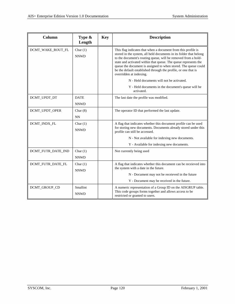
AIS+ Enterprise Edition Version 1.0 Documentation System Administration
SYSCOM, Inc. Page 120 February 1, 2001
Column Type & Length
Key Description
DCMT_WAKE_ROUT_FL Char (1)
NNWD
This flag indicates that when a document from this profile is stored in the system, all held documents in its folder that belong to the document's routing queue, will be removed from a hold-state and activated within that queue. The queue represents the queue the document is assigned to when stored. The queue could be the default established through the profile, or one that is overridden at indexing.
N - Held documents will not be activated.
Y - Held documents in the document's queue will be activated.
DCMT_UPDT_DT DATE
NNWD
The last date the profile was modified.
DCMT_UPDT_OPER Char (8)
NN
The operator ID that performed the last update.
DCMT_INDX_FL Char (1)
NNWD
A flag that indicates whether this document profile can be used for storing new documents. Documents already stored under this profile can still be accessed.
N - Not available for indexing new documents.
Y - Available for indexing new documents.
DCMT_FUTR_DATE_IND Char (1)
NNWD
Not currently being used
DCMT_FUTR_DATE_FL Char (1)
NNWD
A flag that indicates whether this document can be receieved into the system with a date in the future.
N - Document may not be receieved in the future
Y - Document may be received in the future.
DCMT_GROUP_CD Smallint
NNWD
A numeric representation of a Group ID on the AISGRUP table. This code groups forms together and allows access to be restricted or granted to users.

AIS+ Enterprise Edition Version 1.0 Documentation System Administration
SYSCOM, Inc. Page 121 February 1, 2001
AISDLOG - Delete/Undelete Log This table contains information on documents that have been deleted and undeleted, and folders that have been deleted from the system. This table exists because on the FAF deletion of an entity, all elements associated with the entity are also removed at the time of deletion.
Entries to this table are created when a document is either deleted or undeleted (through the use of the AIS+ Document Delete/Undelete function), or when a folder is deleted through the use of the AIS+ Folder Deletion function (AIS+ EE User Reference Manual).
The following table contains the naming conventions used for the AIS+ Delete/Undelete Log table.
DB2 Component AIS+ Supplied Name Your Company Naming Convention
Storage Group N/A
Database N/A
Tablespace AISTSDL
Table AISDLOG
Index AISIXDL1
Insertions to the table can be frequent. A single unique index is supplied that uses the application ID, the folder type, the folder ID, the delete type, and the delete date. The first three keys are in ascending order and the last two are in descending order.
Each AIS+ AISDLOG entry has a length of 207 bytes, 199 bytes of data and 8 bytes for the DB2 header. Each index entry has a length of 41 bytes.
AISDLOG utilizes a single simple tablespace. Since this table is only written to when items are being deleted and delete volume is not normally that great, the locking mechanism should be set to use the "page" (though most shops will utilize "any"). Since insertion is semi-frequent, percent free should be set to 20% and free pages should be set to zero (0). There is no special requirement to have the table reside in any special bufferpool. The data does not need to be erased when the table is dropped. This table is used frequently by the application, so the tablespace should not be closed each time it is used.
For information regarding space calculations, refer to the example for the AIS+ AISAPPL table or the IBM DB2 Installation Guide V6.1, Section 2.2.2 DASD Storage for User Data.

AIS+ Enterprise Edition Version 1.0 Documentation System Administration
SYSCOM, Inc. Page 122 February 1, 2001
The following tables reflect the aforementioned DB2 options required to build AIS+ AISDLOG.
Tablespace DDL Option Value Description
SEGSIZE N/A Simple tablespace does not use segments.
NUMPARTS N/A Simple tablespace does not use partitions.
LOCKSIZE PAGE or ANY Access to this table is by insertion only, though volume should be low.
PRIQTY 168 See calculation above.
SECQTY 0 None required if primary quantity is set to carry all potential deletions.
PCTFREE 20 The table is frequently updated.
FREEPAGE 0 The table is frequently updated.
BUFFERPOOL BP0 Most shops use bufferpool 0 for the majority of their work.
CLOSE NO Table is constantly being accessed.
ERASE NO The data in the table does not need to be erased whenever the table is dropped.

AIS+ Enterprise Edition Version 1.0 Documentation System Administration
SYSCOM, Inc. Page 123 February 1, 2001
Index DDL Option Value Description
UNIQUE Index is unique.
DLOG_APPLIDCD (ASC)
DLOG_FOLDER_TYPE (ASC)
DLOG_FOLDID (ASC)
DLOG_DLTTYPE (DESC)
DLOG_DLTDATE (DESC)
PRIQTY 68 See calculation above.
SECQTY 0 None required if primary quantity is set to carry all potential deletions.
PCTFREE 20 The table can be frequently updated.
FREEPAGE 0 The table can be frequently updated.
BUFFERPOOL BP0 Most shops use bufferpool 0 for the majority of their work.
CLOSE NO Table is constantly being accessed.
ERASE NO The data in the table does not need to be erased whenever the table is dropped.

AIS+ Enterprise Edition Version 1.0 Documentation System Administration
SYSCOM, Inc. Page 124 February 1, 2001
The following information describes the contents of an AIS+ AISDLOG data row:
Column Type & Length Key Description
DLOG_APPLIDCD SMALLINT
NNWD
1:1A Internal numeric value used by all FAF and AIS+ DB2 tables to identify data elements belonging to an application.
DLOG_FOLDER_TYPE Char (2)
NNWD
1:2A The type of folder. The type can be any two alphanumeric combination.
DLOG_FOLDID Char (26)
NNWD
1:3A The folder ID of the item being deleted.
DLOG_DLTTYPE Char (1)
NNWD
1:4D Type of reason.
D - Document Delete
F - Folder Delete
U - Document Undelete
DLOG_DLTDATE TIMESTAMP
NNWD
1:5D The date the function was performed.
DLOG_FOLDTKN TIMESTAMP
NNWD
The FAF internal DB2 timestamp of the folder being processed.
DLOG_CRTESITE Char (4)
NNWD
The IODM CICS region that initially stored the document. This field is not used if a folder has been deleted.
DLOG_OBJTIME TIMESTAMP
NNWD
The FAF internal DB2 timestamp of the document being processed. This field is not used if a folder has been deleted.
DLOG_OBJVERS SMALLINT
NNWD
The document's version number on which the function has been performed. This field is not used if a folder has been deleted.
DLOG_RESNCODE Char (2)
NNWD
A User defined reason code for why the action has taken place.
DLOG_RESNMSSG Char (50)
NNWD
Additional information describing the delete/undelete action.
DLOG_USERID Char (8)
NNWD
The operator ID that performed the function.
DLOG_TERMID Char (8)
NNWD
The terminal ID from which the function was performed.
DLOG_OBJDESC Char (60) The full length name or description of the object
DLOG_RECVDATE Date The date the object was received

AIS+ Enterprise Edition Version 1.0 Documentation System Administration
SYSCOM, Inc. Page 125 February 1, 2001
AISDRSN - Delete/Undelete Reasons This table contains the various reasons for deleting and undeleting documents and deleting folders from the system.
There is no on-line facility within AIS+ to currently administer this table. Building of the table must be accomplished utilizing a DB2 utility or tool.
The following table contains the naming conventions used for the AIS+ Delete/Undelete Reason table.
DB2 Component AIS+ Supplied Name Your Company Naming Convention
Storage Group N/A
Database N/A
Tablespace AISTSRC
Table AISDRSN
Index AISIXDR1
Insertions and modifications to the table are extremely infrequent. A single unique index is supplied (but not required) that uses the application ID and the reason type, and the reason code, all in ascending order.
Each AIS+ AISDRSN entry has a length of 29 bytes, 21 bytes of data and 8 bytes for the DB2 header. Each index entry has a length of 5 bytes.
AISDRSN utilizes a simple single tablespace. Since this table is rarely updated, the locking mechanism should be set to use the "tablespace" (though most shops will utilize "any"). Again, since insertion is rare, both percent free and free pages should both be set to zero (0). There is no special requirement to have the table reside in any special bufferpool. The data does not need to be erased when the table is dropped. This table is used frequently by the application, so the tablespace should not be closed each time it is used.
For information regarding space calculations, refer to the example for the AIS+ AISAPPL table or the IBM DB2 Installation Guide V6.1, Section 2.2.2 DASD Storage for User Data.

AIS+ Enterprise Edition Version 1.0 Documentation System Administration
SYSCOM, Inc. Page 126 February 1, 2001
The following tables reflect the aforementioned DB2 options required to build AIS+ AISDRSN.
Tablespace DDL Option Value Description
SEGSIZE N/A Simple tablespace does not use segments.
NUMPARTS N/A Simple tablespace does not use partitions.
LOCKSIZE TABLESPACE or ANY The table is rarely updated and is used extensively in a read-only fashion.
PRIQTY 12 See calculation above.
SECQTY 0 None required if primary quantity is set to carry all defined reasons.
PCTFREE 0 The table is rarely updated.
FREEPAGE 0 The table is rarely updated.
BUFFERPOOL BP0 Most shops use bufferpool 0 for the majority of their work.
CLOSE NO Table is constantly being accessed.
ERASE NO The data in the table does not need to be erased whenever the table is dropped.

AIS+ Enterprise Edition Version 1.0 Documentation System Administration
SYSCOM, Inc. Page 127 February 1, 2001
Index DDL Option Value Description
UNIQUE Index is unique.
DRSN_APPLIDCD (ASC)
DRSN_RSNTYPE (ASC)
DRSN_RSNCODE (ASC)
PRIQTY 12 See calculation above.
SECQTY 0 None required if primary quantity is set to carry all defined reasons.
PCTFREE 0 The table is rarely updated.
FREEPAGE 0 The table is rarely updated.
BUFFERPOOL BP0 Most shops use bufferpool 0 for the majority of their work.
CLOSE NO Table is constantly being accessed.
ERASE NO The data in the table does not need to be erased whenever the table is dropped.
The following information describes the contents of an AIS+ AISDRSN data row:
Column Type & Length Key Description
DRSN_APPLIDCD SMALLINT
NNWD
1:1A Internal numeric value used by all FAF and AIS+ DB2 tables to identify data elements belonging to an application.
DRSN_RSNTYPE Char (1)
NNWD
1:2A Type of reason.
D - Document Delete
F - Folder Delete
U - Document Undelete
DRSN_RSNCODE Char (2)
NNWD
1:3A A User defined reason code for why the action has taken place.
DRSN_RSNMSSG Char (16)
NNWD
A corresponding brief message associated with the reason code.

AIS+ Enterprise Edition Version 1.0 Documentation System Administration
SYSCOM, Inc. Page 128 February 1, 2001
AISDTAB - Default Folder Tabs Each document (or form), for an individual application, must be assigned to a tab within a folder. This table provides a default assignment used when the document is being indexed for storage.
Entries to this table are generated through the use of the AIS+ Form Profile Administration function (AIS+ EE User Reference Manual).
The following table contains the naming conventions used for the AIS+ Default Folder Tab table.
DB2 Component AIS+ Supplied Name Your Company Naming Convention
Storage Group N/A
Database N/A
Tablespace AISTSDT
Table AISDTAB
Index AISIXDT1
Insertions and modifications to the table are infrequent. One unique index is supplied (but not required) that uses the application ID, the form name, and the folder type all in ascending order.
Each AIS+ AISDTAB entry has a length of 46 bytes, 38 bytes of data and 8 bytes for the DB2 header. The index entry has a length of 20 bytes.
AISDTAB utilizes a simple single tablespace. Since this table is rarely updated, the locking mechanism should be set to use the "tablespace" (though most shops will utilize "any"). Again, since insertion is rare, both percent free and free pages should both be set to zero (0). There is no special requirement to have the table reside in any special bufferpool. The data does not need to be erased when the table is dropped. This table is used frequently by the application, so the tablespace should not be closed each time it is used.
For information regarding space calculations, refer to the example for the AIS+ AISAPPL table or the IBM DB2 Installation Guide V6.1, Section 2.2.2 DASD Storage for User Data.

AIS+ Enterprise Edition Version 1.0 Documentation System Administration
SYSCOM, Inc. Page 129 February 1, 2001
The following tables reflect the aforementioned DB2 options required to build AIS+ AISDTAB.
Tablespace DDL Option Value Description
SEGSIZE N/A Simple tablespace does not use segments.
NUMPARTS N/A Simple tablespace does not use partitions.
LOCKSIZE TABLESPACE or ANY The table is rarely updated and is used extensively in a read-only fashion.
PRIQTY 12 See calculation above.
SECQTY 0 None required if primary quantity is set to carry all defined default tab combinations.
PCTFREE 0 The table is rarely updated.
FREEPAGE 0 The table is rarely updated.
BUFFERPOOL BP0 Most shops use bufferpool 0 for the majority of their work.
CLOSE NO Table is constantly being accessed.
ERASE NO The data in the table does not need to be erased whenever the table is dropped.

AIS+ Enterprise Edition Version 1.0 Documentation System Administration
SYSCOM, Inc. Page 130 February 1, 2001
Index DDL Option Value Description
UNIQUE Index is unique.
DTAB_APPLIDCD (ASC)
DTAB_FORMNUM (ASC)
DTAB_FOLDTYPE (ASC)
PRIQTY 12 See calculation above.
SECQTY 0 None required if primary quantity is set to carry all defined default tab combinations.
PCTFREE 0 The table is rarely updated.
FREEPAGE 0 The table is rarely updated.
BUFFERPOOL BP0 Most shops use bufferpool 0 for the majority of their work.
CLOSE NO Table is constantly being accessed.
ERASE NO The data in the table does not need to be erased whenever the table is dropped.
The following information describes the contents of an AIS+ AISDTAB data row:
Column Type & Length
Key Description
DTAB_APPLIDCD SMALLINT
NN
1:1A Internal numeric value used by all FAF and AIS+ DB2 tables to identify data elements belonging to an application. This is system generated upon entry of a new application.
DTAB_FORMNUM Char (16)
NN
1:2A Name of the form or document.
DTAB_FOLDTYPE Char (2)
NN
1:3A The type of folder. The type can be any two alphanumeric combination.
DTAB_DESCRIPTION Char (16)
NN
The full length name or description of the tab.
DTAB_TABTYPE Char (2)
NN
The tab acronym. The acronym can be any two alphanumeric combination.

AIS+ Enterprise Edition Version 1.0 Documentation System Administration
SYSCOM, Inc. Page 131 February 1, 2001
AISFLDR - Folder Profile Each folder type, that will be processed within the individual application of the AIS+ software must be defined to the system. An entry represents the characteristics, or profile, the folder will be governed by while executing under AIS+.
Entries are created for this table through the use of the AIS+ Folder Profile Administration function (AIS+ EE User Reference Manual).
The following table contains the naming conventions used for the AIS+ Folder Profile table.
DB2 Component AIS+ Supplied Name Your Company Naming Convention
Storage Group N/A
Database N/A
Tablespace AISTSFP
Table AISFLDR
Index AISIXFP1
AISIXFP2
Insertions and modifications to the table are infrequent. Two unique indices are supplied. The first uses the application ID and the folder type, both in ascending order. The second uses the application ID and the internal numeric folder type code, both in ascending order.
Each AIS+ AISFLDR entry has a length of 259 bytes, 251 bytes of data and 8 bytes for the DB2 header. The first index entry has a length of 4 bytes and the second has a length of 4 bytes.
AISFLDR utilizes a simple single tablespace. Since this table is rarely updated, the locking mechanism should be set to use the "tablespace" (though most shops will utilize "any"). Again, since insertion is rare, both percent free and free pages should both be set to zero (0). There is no special requirement to have the table reside in any special bufferpool. The data does not need to be erased when the table is dropped. This table is used frequently by the application, so the tablespace should not be closed each time it is used.
For information regarding space calculations, refer to the example for the AIS+ AISAPPL table or the IBM DB2 Installation Guide V6.1, Section 2.2.2 DASD Storage for User Data.

AIS+ Enterprise Edition Version 1.0 Documentation System Administration
SYSCOM, Inc. Page 132 February 1, 2001
The following tables reflect the aforementioned DB2 options required to build AIS+ AISFLDR.
Tablespace DDL Option Value Description
SEGSIZE N/A Simple tablespace does not use segments.
NUMPARTS N/A Simple tablespace does not use partitions.
LOCKSIZE TABLESPACE or ANY The table is rarely updated and is used extensively in a read-only fashion.
PRIQTY 12 See calculation above.
SECQTY 0 None required if primary quantity is set to carry all defined folder profiles.
PCTFREE 0 The table is rarely updated.
FREEPAGE 0 The table is rarely updated.
BUFFERPOOL BP0 Most shops use bufferpool 0 for the majority of their work.
CLOSE NO Table is constantly being accessed.
ERASE NO The data in the table does not need to be erased whenever the table is dropped.
Index 1 DDL Option Value Description
UNIQUE Index is unique.
FLDR_APPLIDCD (ASC)
FLDR_FOLDTYPE (ASC)
PRIQTY 12 See calculation above.
SECQTY 0 None required if primary quantity is set to carry all defined folder profiles.
PCTFREE 0 The table is rarely updated.
FREEPAGE 0 The table is rarely updated.
BUFFERPOOL BP0 Most shops use bufferpool 0 for the majority of their work.
CLOSE NO Table is constantly being accessed.
ERASE NO The data in the table does not need to be erased whenever the table is dropped.

AIS+ Enterprise Edition Version 1.0 Documentation System Administration
SYSCOM, Inc. Page 133 February 1, 2001
Index 2 DDL Option Value Description
UNIQUE Index is unique.
FLDR_APPLIDCD (ASC)
FLDR_FOLDTYCD (ASC)
PRIQTY 12 See calculation above.
SECQTY 0 None required if primary quantity is set to carry all defined folder profiles.
PCTFREE 0 The table is rarely updated.
FREEPAGE 0 The table is rarely updated.
BUFFERPOOL BP0 Most shops use bufferpool 0 for the majority of their work.
CLOSE NO Table is constantly being accessed.
ERASE NO The data in the table does not need to be erased whenever the table is dropped.
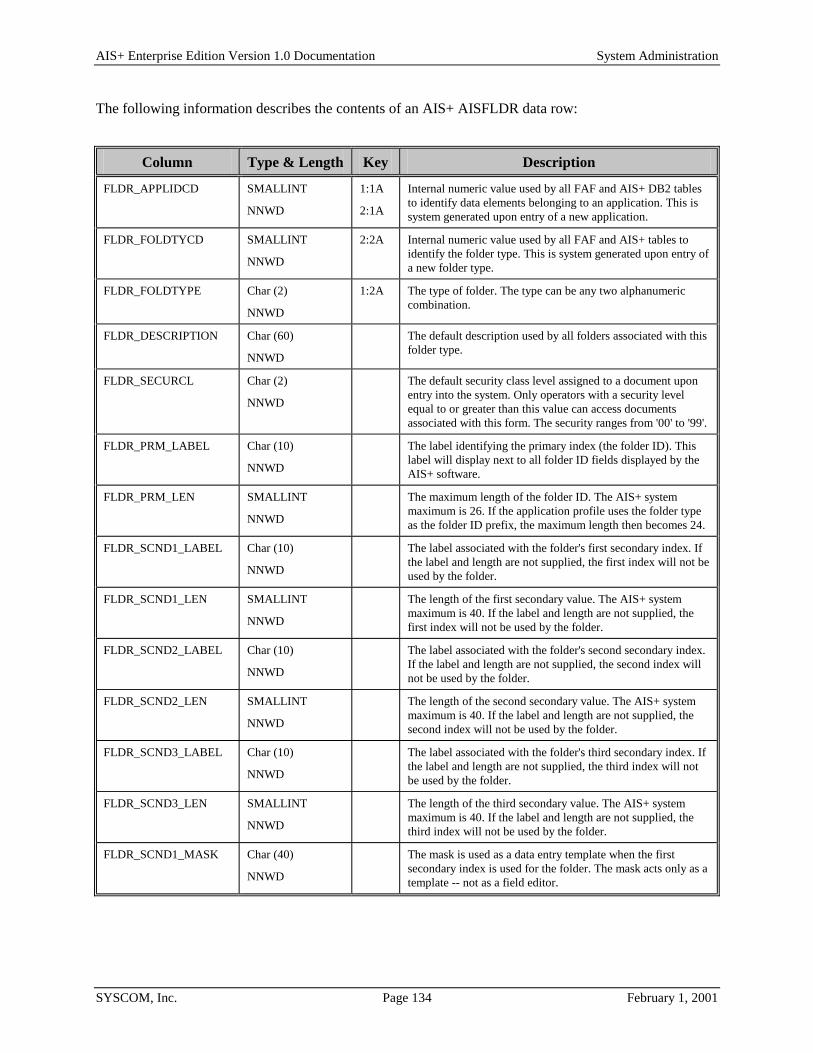
AIS+ Enterprise Edition Version 1.0 Documentation System Administration
SYSCOM, Inc. Page 134 February 1, 2001
The following information describes the contents of an AIS+ AISFLDR data row:
Column Type & Length Key Description
FLDR_APPLIDCD SMALLINT
NNWD
1:1A
2:1A
Internal numeric value used by all FAF and AIS+ DB2 tables to identify data elements belonging to an application. This is system generated upon entry of a new application.
FLDR_FOLDTYCD SMALLINT
NNWD
2:2A Internal numeric value used by all FAF and AIS+ tables to identify the folder type. This is system generated upon entry of a new folder type.
FLDR_FOLDTYPE Char (2)
NNWD
1:2A The type of folder. The type can be any two alphanumeric combination.
FLDR_DESCRIPTION Char (60)
NNWD
The default description used by all folders associated with this folder type.
FLDR_SECURCL Char (2)
NNWD
The default security class level assigned to a document upon entry into the system. Only operators with a security level equal to or greater than this value can access documents associated with this form. The security ranges from '00' to '99'.
FLDR_PRM_LABEL Char (10)
NNWD
The label identifying the primary index (the folder ID). This label will display next to all folder ID fields displayed by the AIS+ software.
FLDR_PRM_LEN SMALLINT
NNWD
The maximum length of the folder ID. The AIS+ system maximum is 26. If the application profile uses the folder type as the folder ID prefix, the maximum length then becomes 24.
FLDR_SCND1_LABEL Char (10)
NNWD
The label associated with the folder's first secondary index. If the label and length are not supplied, the first index will not be used by the folder.
FLDR_SCND1_LEN SMALLINT
NNWD
The length of the first secondary value. The AIS+ system maximum is 40. If the label and length are not supplied, the first index will not be used by the folder.
FLDR_SCND2_LABEL Char (10)
NNWD
The label associated with the folder's second secondary index. If the label and length are not supplied, the second index will not be used by the folder.
FLDR_SCND2_LEN SMALLINT
NNWD
The length of the second secondary value. The AIS+ system maximum is 40. If the label and length are not supplied, the second index will not be used by the folder.
FLDR_SCND3_LABEL Char (10)
NNWD
The label associated with the folder's third secondary index. If the label and length are not supplied, the third index will not be used by the folder.
FLDR_SCND3_LEN SMALLINT
NNWD
The length of the third secondary value. The AIS+ system maximum is 40. If the label and length are not supplied, the third index will not be used by the folder.
FLDR_SCND1_MASK Char (40)
NNWD
The mask is used as a data entry template when the first secondary index is used for the folder. The mask acts only as a template -- not as a field editor.

AIS+ Enterprise Edition Version 1.0 Documentation System Administration
SYSCOM, Inc. Page 135 February 1, 2001
Column Type & Length Key Description
FLDR_SCND2_MASK Char (40)
NNWD
The mask is used as a data entry template when the second secondary index is used for the folder. The mask acts only as a template -- not as a field editor.
FLDR_SCND3_MASK Char (40)
NNWD
The mask is used as a data entry template when the third secondary index is used for the folder. The mask acts only as a template -- not as a field editor.
FLDR_SCND1_EDITNO Char (2)
NNWD
The Edit Number for secondary index 1 is passed to the Field Edit Exit, when a folder is added or updated.
FLDR_SCND2_EDITNO Char (2)
NNWD
The Edit Number for secondary index 2 is passed to the Field Edit Exit, when a folder is added or updated.
FLDR_SCND3_EDITNO Char (2)
NNWD
The Edit Number for secondary index 3 is passed to the Field Edit Exit, when a folder is added or updated.
FLDR_DLTE_IND Char (1)
NNWD
An indicator that represents the automatic deletion of a folder when the last document has been removed (deleted or moved) from the folder.
N - Do not delete empty folders.
Y - Delete empty folders.
FLDR_SCND1_MIN SMALLINT
NNWD
The minimum number of positions that must be entered for the first secondary index when performing wildcard searches for folders with similar indices. Only valid if the first secondary index is being used.
FLDR_SCND2_MIN SMALLINT
NNWD
The minimum number of positions that must be entered for the second secondary index when performing wildcard searches for folders with similar indices. Only valid if the second secondary index is being used.
FLDR_SCND3_MIN SMALLINT
NNWD
The minimum number of positions that must be entered for the third secondary index when performing wildcard searches for folders with similar indices. Only valid if the third secondary index is being used.
FLDR_SEARCH_MIN SMALLINT
NNWD
The minimum number of positions that must be entered for the folder ID when performing wildcard searches for a group of folders.

AIS+ Enterprise Edition Version 1.0 Documentation System Administration
SYSCOM, Inc. Page 136 February 1, 2001
AISGOPR - Operator Group Assignment Each group of forms that an operator can access / view must be defined to the system.
Entries to this table are created during the assignment of groups using the AIS+ Operator Group Assignment function (AIS+ EE User Reference Manual). Additionally, entries are added during an Operator Profile Copy option. Further, one entry is added each time that either a new application or operator are created.
The following table contains the naming conventions used for the AIS+ Operator Group Assignment table.
DB2 Component AIS+ Supplied Name Your Company Naming Convention
Storage Group N/A
Database N/A
Tablespace AISTSGP
Table AISGOPR
Index AISIXGP1
AISIXGP2
Insertions to this table are infrequent after the initial setup of existing operators. Two (2) indices are supplied. The first index is unique and uses the application ID, the group code and the operator's ID, all in ascending order. The second index is non-unique and uses the application ID and the operator's ID, all in ascending order.
Each AISGOPR entry has a length of 20 bytes, 12 bytes of data and 8 bytes for the DB2 header. The two indices have lengths of 12 and 10 bytes respectively.
AISGOPR utilizes a simple tablespace. Since this table is rarely updated, the locking mechanism should be set to use the "tablespace" (though most shops will utilize "any"). The percent free should be set to 10 and free pages should be set to 10. There is no special requirement to have the table reside in any special bufferpool. The data does not need to be erased when the table is dropped. This table is used frequently by the application, so the tablespace should not be closed each time it is used.
For information regarding space calculations, refer to the example for the AIS+ AISAPPL table or the IBM DB2 Installation Guide V6.1, Section 2.2.2 DASD Storage for User Data.

AIS+ Enterprise Edition Version 1.0 Documentation System Administration
SYSCOM, Inc. Page 137 February 1, 2001
The following tables reflect the aforementioned DB2 options required to build AISGOPR:
Tablespace DDL Option Value Description
SEGSIZE N/A Simple tablespace does not use segments.
NUMPARTS N/A Simple tablespace does not use partitions.
LOCKSIZE TABLESPACE or ANY The table is rarely updated and is used extensively in a read-only fashion.
PRIQTY 20 See calculations above.
SECQTY 10 See calculations above.
PCTFREE 10 The table is rarely updated.
FREEPAGE 10 The table is rarely updated.
BUFFERPOOL BP0 Most shops use bufferpool 0 for the majority of their work.
CLOSE NO Table is constantly being accessed.
ERASE NO The data in the table does not need to be erased whenever the table is dropped.
Index 1 DDL Option Value Description
UNIQUE Index is unique.
GOPR_APPLIDCD (ASC)
GOPR_GROUP_CD (ASC)
GOPR_OPER_ID (ASC)
PRIQTY 20 See calculation above.
SECQTY 10 None required if primary quantity is set to carry all group assignment profiles.
PCTFREE 10 The table is rarely updated.
FREEPAGE 10 The table is rarely updated.
BUFFERPOOL BP0 Most shops use bufferpool 0 for the majority of their work.
CLOSE NO Table is constantly being accessed.
ERASE NO The data in the table does not need to be erased whenever the table is dropped.

AIS+ Enterprise Edition Version 1.0 Documentation System Administration
SYSCOM, Inc. Page 138 February 1, 2001
Index 2 DDL Option Value Description
UNIQUE Index is unique.
GOPR_APPLIDCD (ASC)
GOPR_OPER_ID (ASC)
PRIQTY 16 See calculation above.
SECQTY 10 None required if primary quantity is set to carry all defined group assignments.
PCTFREE 10 The table is rarely updated.
FREEPAGE 10 The table is rarely updated.
BUFFERPOOL BP0 Most shops use bufferpool 0 for the majority of their work.
CLOSE NO Table is constantly being accessed.
ERASE NO The data in the table does not need to be erased whenever the table is dropped.
The following information describes the contents of an AISGOPR data row:
Column Type & Length Key Description
GOPR_APPLIDCD SMALLINT
NNWD
1:1A
2:1A
Internal numeric value used by all FAF and AIS+ DB2 tables to identify data elements belonging to an application.
GOPR_GROUP_CD SMALLINT
NNWD
1:2A
Internal numeric value used by AIS+ tables to identify forms that belong to a group.
GOPR_OPER_ID Char (8)
NN
1:3A2:2A
Contains a valid AIS+ Operator ID.

AIS+ Enterprise Edition Version 1.0 Documentation System Administration
SYSCOM, Inc. Page 139 February 1, 2001
AISGRUP - Group Profile Each unique group to which a form is assigned must be defined to the system.
Entries to this table are created during the creation or modification of forms using the AIS+ Form Profile function (AIS+ EE User Reference Manual).
The following table contains the naming conventions used for the AIS+ Group Profile table.
DB2 Component AIS+ Supplied Name Your Company Naming Convention
Storage Group N/A
Database N/A
Tablespace AISTSGT
Table AISGRUP
Index AISIXGT1
Insertions to this table are infrequent. One (1) unique index is supplied. This index uses the application ID and the group code, all in ascending order.
Each AISGRUP entry has a length of 20 bytes, 12 bytes of data and 8 bytes for the DB2 header. The index has a length of 4 bytes.
AISGRUP utilizes a simple tablespace. Since this table is rarely updated, the locking mechanism should be set to use the "tablespace" (though most shops will utilize "any"). The percent free should be set to 10 and free pages should be set to 10. There is no special requirement to have the table reside in any special bufferpool. The data does not need to be erased when the table is dropped. This table is used frequently by the application, so the tablespace should not be closed each time it is used.
For information regarding space calculations, refer to the example for the AIS+ AISAPPL table or the IBM DB2 Installation Guide V6.1, Section 2.2.2 DASD Storage for User Data.
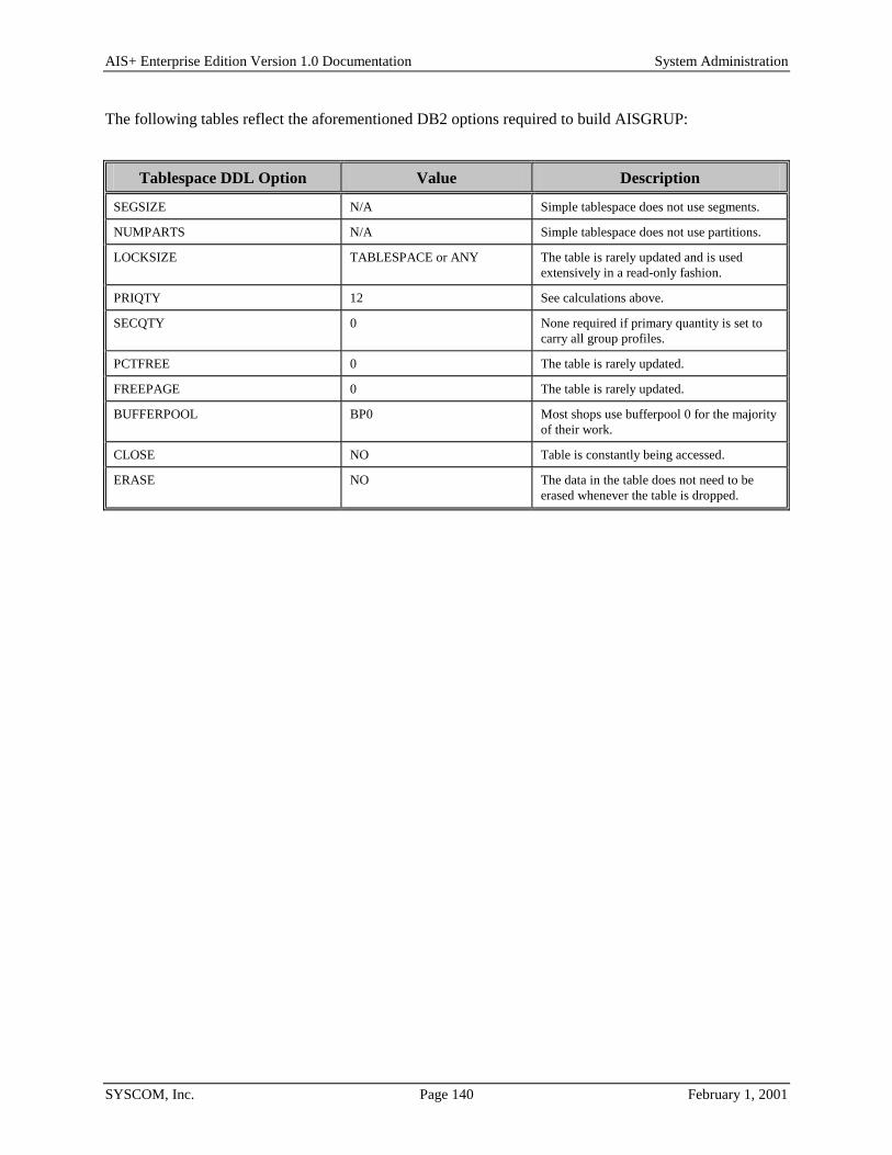
AIS+ Enterprise Edition Version 1.0 Documentation System Administration
SYSCOM, Inc. Page 140 February 1, 2001
The following tables reflect the aforementioned DB2 options required to build AISGRUP:
Tablespace DDL Option Value Description
SEGSIZE N/A Simple tablespace does not use segments.
NUMPARTS N/A Simple tablespace does not use partitions.
LOCKSIZE TABLESPACE or ANY The table is rarely updated and is used extensively in a read-only fashion.
PRIQTY 12 See calculations above.
SECQTY 0 None required if primary quantity is set to carry all group profiles.
PCTFREE 0 The table is rarely updated.
FREEPAGE 0 The table is rarely updated.
BUFFERPOOL BP0 Most shops use bufferpool 0 for the majority of their work.
CLOSE NO Table is constantly being accessed.
ERASE NO The data in the table does not need to be erased whenever the table is dropped.

AIS+ Enterprise Edition Version 1.0 Documentation System Administration
SYSCOM, Inc. Page 141 February 1, 2001
Index 1 DDL Option Value Description
UNIQUE Index is unique.
GRUP_APPLIDCD (ASC)
GRUP_GROUP_CD (ASC)
PRIQTY 12 See calculation above.
SECQTY 0 None required if primary quantity is set to carry all group assignment profiles.
PCTFREE 0 The table is rarely updated.
FREEPAGE 0 The table is rarely updated.
BUFFERPOOL BP0 Most shops use bufferpool 0 for the majority of their work.
CLOSE NO Table is constantly being accessed.
ERASE NO The data in the table does not need to be erased whenever the table is dropped.
The following information describes the contents of an AISGRUP data row:
Column Type & Length Key Description
GRUP_APPLIDCD SMALLINT
NNWD
1:1A
Internal numeric value used by all FAF and AIS+ DB2 tables to identify data elements belonging to an application.
GRUP_GROUP_CD SMALLINT
NNWD
1:2A
Internal numeric value used by AIS+ tables to identify forms that belong to a group.
GRUP_GROUP_ID Char (8)
NN
Contains a valid AIS+ Group ID.

AIS+ Enterprise Edition Version 1.0 Documentation System Administration
SYSCOM, Inc. Page 142 February 1, 2001
AISMSGS - AIS+ Messages Each message used by AIS+ and the various system exits is maintained in this table.
There is no current method of entering messages through the AIS+ on-line system. All entries must be made through the use of a DB2 utility or tool.
The following table contains the naming conventions used for the AIS+ Message table.
DB2 Component AIS+ Supplied Name Your Company Naming Convention
Storage Group N/A
Database N/A
Tablespace AISTSMS
Table AISMSGS
Index AISIXMS1
Insertions and modifications to the table are extremely infrequent. A single unique index is supplied that uses the message code in ascending order.
Each AIS+ AISMSGS entry has a length of 88 bytes, 80 bytes of data and 8 bytes for the DB2 header. Each index entry has a length of 8 bytes.
AISMSGS utilizes a simple single tablespace. Since this table is rarely updated, the locking mechanism should be set to use the "tablespace" (though most shops will utilize "any"). Again, since insertion is rare, both percent free and free pages should both be set to zero (0). There is no special requirement to have the table reside in any special bufferpool. The data does not need to be erased when the table is dropped. This table is used frequently by the application, so the tablespace should not be closed each time it is used.
For information regarding space calculations, refer to the example for the AIS+ AISAPPL table or the IBM DB2 Installation Guide V6.1, Section 2.2.2 DASD Storage for User Data.

AIS+ Enterprise Edition Version 1.0 Documentation System Administration
SYSCOM, Inc. Page 143 February 1, 2001
The following tables reflect the aforementioned DB2 options required to build AIS+ AISMSGS.
Tablespace DDL Option Value Description
SEGSIZE N/A Simple tablespace does not use segments.
NUMPARTS N/A Simple tablespace does not use partitions.
LOCKSIZE TABLESPACE or ANY The table is rarely updated and is used extensively in a read-only fashion.
PRIQTY 48 See calculation above.
SECQTY 0 None required if primary quantity is set to carry all defined messages.
PCTFREE 0 The table is rarely updated.
FREEPAGE 0 The table is rarely updated.
BUFFERPOOL BP0 Most shops use bufferpool 0 for the majority of their work.
CLOSE NO Table is constantly being accessed.
ERASE NO The data in the table does not need to be erased whenever the table is dropped.
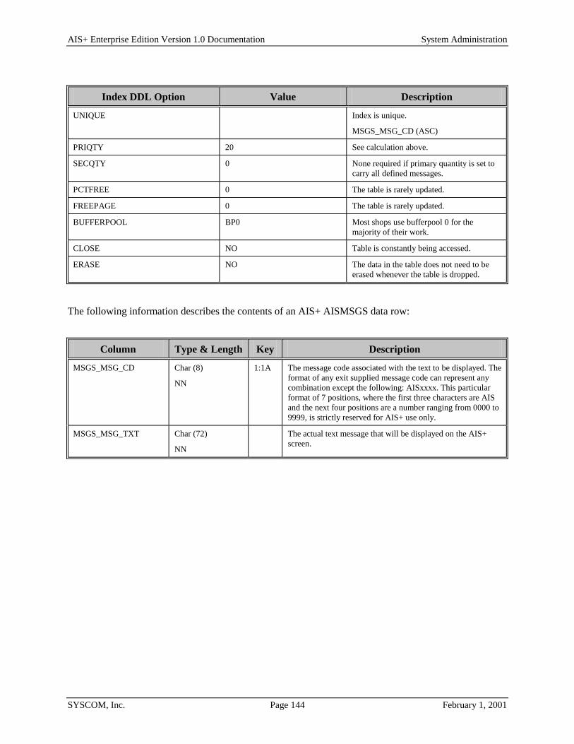
AIS+ Enterprise Edition Version 1.0 Documentation System Administration
SYSCOM, Inc. Page 144 February 1, 2001
Index DDL Option Value Description
UNIQUE Index is unique.
MSGS_MSG_CD (ASC)
PRIQTY 20 See calculation above.
SECQTY 0 None required if primary quantity is set to carry all defined messages.
PCTFREE 0 The table is rarely updated.
FREEPAGE 0 The table is rarely updated.
BUFFERPOOL BP0 Most shops use bufferpool 0 for the majority of their work.
CLOSE NO Table is constantly being accessed.
ERASE NO The data in the table does not need to be erased whenever the table is dropped.
The following information describes the contents of an AIS+ AISMSGS data row:
Column Type & Length Key Description
MSGS_MSG_CD Char (8)
NN
1:1A The message code associated with the text to be displayed. The format of any exit supplied message code can represent any combination except the following: AISxxxx. This particular format of 7 positions, where the first three characters are AIS and the next four positions are a number ranging from 0000 to 9999, is strictly reserved for AIS+ use only.
MSGS_MSG_TXT Char (72)
NN
The actual text message that will be displayed on the AIS+ screen.

AIS+ Enterprise Edition Version 1.0 Documentation System Administration
SYSCOM, Inc. Page 145 February 1, 2001
AISOPAS - Operator Assignment Each queue (route unit/route code) that an operator can process must be defined to the system.
Entries to this table are created during the assignment queues using the AIS+ Operator Assignment function (AIS+ EE User Reference Manual).
The following table contains the naming conventions used for the AIS+ Operator Assignment table. AISOPAS is a view of the IBM FAF User Assignment table (EYPTWEAS).
DB2 Component AIS+ Supplied Name Your Company Naming Convention
Storage Group N/A
Database N/A
Tablespace EYPSWEAS
Table EYPTWEAS
Index EYPIWEAS1452U
EYPIWEAS12345CU
View AISOPAS
Insertions and modifications to the table can be extremely frequent. Two (2) unique indices are supplied by IBM. The first index uses the application ID, the assigned route unit, the assigned route code, and the operator's ID, all in ascending order. The second index uses the application ID, the operator's ID, the queue priority, the assigned route unit, and the assigned route code, all in ascending order (except the queue priority which is in descending order).
Each AIS+ AISOPAS entry has a length of 31 bytes, 23 bytes of data and 8 bytes for the DB2 header. The two indices have lengths of 20 and 22 bytes respectively.
EYPTWEAS utilizes a simple tablespace. Since this table has a potential of being frequently updated, the locking mechanism should be set to use the "page" (though most shops will utilize "any"). The percent free should be set to 20 and free pages should be set to zero. There is no special requirement to have the table reside in any special bufferpool. The data does not need to be erased when the table is dropped. This table is used frequently by the application, so the tablespace should not be closed each time it is used.
For information regarding space calculations, refer to the example for the AIS+ AISAPPL table or the IBM DB2 Installation Guide V6.1, Section 2.2.2 DASD Storage for User Data.

AIS+ Enterprise Edition Version 1.0 Documentation System Administration
SYSCOM, Inc. Page 146 February 1, 2001
The following tables reflect the aforementioned DB2 options required to build FAF EYPTWEAS:
Tablespace DDL Option Value Description
SEGSIZE N/A Simple tablespace does not use segments.
NUMPARTS N/A Simple tablespace does not use partitions.
LOCKSIZE PAGE or ANY The table has the potential for constant update and is accessed fairly heavy during the workflow process.
PRIQTY 12 See calculation above.
SECQTY 0 None required if primary quantity is set to carry all defined folder profiles.
PCTFREE 20 The table is frequently updated.
FREEPAGE 0 The table is frequently updated.
BUFFERPOOL BP0 Most shops use bufferpool 0 for the majority of their work.
CLOSE NO Table is constantly being accessed.
ERASE NO The data in the table does not need to be erased whenever the table is dropped.
Index 1 DDL Option Value Description
UNIQUE Index is unique.
APPLIDCD (ASC)
RUNIT (ASC)
RCODE (ASC)
USERID(ASC)
PRIQTY 12 See calculation above.
SECQTY 0 None required if primary quantity is set to carry all defined folder profiles.
PCTFREE 20 The table is frequently updated.
FREEPAGE 0 The table is frequently updated.
BUFFERPOOL BP0 Most shops use bufferpool 0 for the majority of their work.
Index 1 DDL Option Value Description
CLOSE NO Table is constantly being accessed.
ERASE NO The data in the table does not need to be erased whenever the table is dropped.

AIS+ Enterprise Edition Version 1.0 Documentation System Administration
SYSCOM, Inc. Page 147 February 1, 2001
Index 2 DDL Option Value Description
UNIQUE Index is unique.
APPLIDCD (ASC)
USERID (ASC)
QPRTY (DESC)
RUNIT (ASC)
RCODE (ASC)
PRIQTY 12 See calculation above.
SECQTY 0 None required if primary quantity is set to carry all defined assignments.
PCTFREE 20 The table is frequently updated.
FREEPAGE 0 The table is frequently updated.
BUFFERPOOL BP0 Most shops use bufferpool 0 for the majority of their work.
CLOSE NO Table is constantly being accessed.
ERASE NO The data in the table does not need to be erased whenever the table is dropped.
The following information describes the contents of a FAF EYPTWEAS data row:
FAF Column (AIS+ View Column)
Type & Length Key Description
APPLIDCD
(OPAS_APPL_ID_CD)
SMALLINT
NNWD
1:1A
2:1A
Internal numeric value used by all FAF and AIS+ DB2 tables to identify data elements belonging to an application.
USERID
(OPAS_OPER_ID)
Char (8)
NN
1:4A
2:2A
Operator ID.
QPRTY
(OPAS_QUE_PRTY )
SMALLINT
NNWD
2:3D Currently not used. Always zero (0).
RUNIT
(OPAS_UNIT_CODE)
INTEGER
NNWD
1:2A
2:4A
The route unit portion of the RTCODE/RUNIT combination that identify a queue.
RCODE
(OPAS_ROUT_CODE)
Char (6)
NNWD
1:3A
2:5A
The route code portion of the RTCODE/RUNIT combination that identify a queue.
ASGNSTAT
(OPAS_STATUS_FL)
Char (1)
NNWD
Current access status of operator's ability to process queue.
A - Active, operator can process queue contents.
I - Inactive, operator can not process queue contents.

AIS+ Enterprise Edition Version 1.0 Documentation System Administration
SYSCOM, Inc. Page 148 February 1, 2001
AISOPPF - Operator Profile Each operator/user who needs access to an application within AIS+ must be defined to the system.
Entries to this table are generated through the use of the AIS+ Operator Security Profile Administration, the AIS+ Operator Copy, and the AIS+ Operator Assignment functions (AIS+ EE User Reference Manual). System Administrator IDs are generated through the use of the AIS+ Initial Application Profile Creation function (AIS+ EE System Administration Manual).
The following table contains the naming conventions used for the AIS+ Operator Profile table.
DB2 Component AIS+ Supplied Name Your Company Naming Convention
Storage Group N/A
Database N/A
Tablespace AISTSOP
Table AISOPPF
Index AISIXOP1
Insertions and modifications to the table can be frequent. A single unique index is supplied that uses the operator ID and the application ID code, both in ascending order.
Each AIS+ AISOPPF entry has a length of 109 bytes, 101 bytes of data and 8 bytes for the DB2 header. Each index entry has a length of 10 bytes.
AISOPPF utilizes a segmented tablespace. Since this table can be moderately updated, the locking mechanism should be set to use a "page" (though most shops will utilize "any"). With a potential high insertion rate, percent free should be set to 20%. Free pages should be set to zero (0) only for the fact that the number of overall pages is not that great and mass volume insertions normally will not occur after the application has been established. There is no special requirement to have the table reside in any special bufferpool. The data does not need to be erased when the table is dropped. This table is used frequently by the application, so the tablespace should not be closed each time it is used.
For information regarding space calculations, refer to the example for the AIS+ AISAPPL table or the IBM DB2 Installation Guide V6.1, Section 2.2.2 DASD Storage for User Data.

AIS+ Enterprise Edition Version 1.0 Documentation System Administration
SYSCOM, Inc. Page 149 February 1, 2001
The following tables reflect the aforementioned DB2 options required to build AIS+ AISOPPF.
Tablespace DDL Option Value Description
SEGSIZE 4 This is a small segmented table.
NUMPARTS N/A Simple tablespace does not use partitions.
LOCKSIZE PAGE or ANY The table is rarely updated and is used extensively in a read-only fashion.
PRIQTY 48 See calculation above.
SECQTY 0 None required if primary quantity is set to carry all defined operator profiles.
PCTFREE 20 The table is rarely updated.
FREEPAGE 0 The table is rarely updated.
BUFFERPOOL BP0 Most shops use bufferpool 0 for the majority of their work.
CLOSE NO Table is constantly being accessed.
ERASE NO The data in the table does not need to be erased whenever the table is dropped.
Index DDL Option Value Description
UNIQUE Index is unique.
OPPF_OPERATOR_ID (ASC)
OPPF_APPL_ID_CD (ASC)
PRIQTY 20 See calculation above.
SECQTY 0 None required if primary quantity is set to carry all defined operator profiles.
PCTFREE 10 The table is rarely updated.
FREEPAGE 0 The table is rarely updated.
BUFFERPOOL BP0 Most shops use bufferpool 0 for the majority of their work.
CLOSE NO Table is constantly being accessed.
ERASE NO The data in the table does not need to be erased whenever the table is dropped.

AIS+ Enterprise Edition Version 1.0 Documentation System Administration
SYSCOM, Inc. Page 150 February 1, 2001
The following information describes the contents of an AIS+ AISOPPF data row:
Column Type & Length
Key Description
OPPF_APPL_ID_CD SMALLINT NNWD
1:2A Internal numeric value used by all FAF and AIS+ DB2 tables to identify data elements belonging to an application.
OPPF_OPERATOR_ID Char (8) NNWD
1:1A The ID value used by an operator to access an application.
OPPF_FIRST_NAME Char (10) NNWD
The operator's first name.
OPPF_MIDDLE_INIT Char (1) NNWD
The operator's middle initial.
OPPF_LAST_NAME Char (20) NNWD
The operator's last name.
OPPF_EMPLY_STATUS Char (1) NNWD
The current access status of the operator. A - Active, able to access the application. I - Inactive, unable to access the application.
OPPF_PASS_WORD Char (8) NNWD
The password associated with the ID in accessing the application.
OPPF_DEF_FLDR_TYP Char (2) NNWD
The type of folder. The type can be any two alphanumeric combination that exists within the folder profile table. This is the default (or primary) folder type accessible by the operator.
OPPF_DOC_FLDR_LVL Char (2) NNWD
The security class level assigned to the operator in accessing folders and documents. Only those items with a security equal to and lower can be accessed. The value ranges from '00' to '99.
OPPF_DEF_UNIT_CD INTEGER NNWD
The unit code the operator is assigned. This default value is used when assigning queue assignments.
OPPF_SECUR_ADM_IND Char (1) NNWD
Y - The Operator will have access to the AIS+ Operator Security function.
N - The Operator will not have access to security profiles. OPPF_APPL_ADM_IND Char (1)
NNWD Y - The Operator will have access to the AIS+ Application
Profile Administration. N - The Operator will not have access to change application
profile components. OPPF_WKFL_ADM_IND Char (1)
NNWD Y - The Operator will have access to the AIS+ Unit Code
Profile, the AIS+ Unit/Route Code Profile, and the AIS+ RLOB/Tran Type Profile functions.
N - The Operator will not have access to change any of the workflow administration profiles.
OPPF_QASG_ADM_IND Char (1) NNWD
Y - Operator will be able to add new queue assignments and be able to update other operators' queue assignments.
N - Operator will be able to update (active, inactive) status only for his/her own routing queues. Operator will not be able to add new queue assignments.
OPPF_OPER_ASGN_IND Char (1) NNWD
Y - The operator will have access to the AIS+ Operator Assignment function.
N - Operator will not have access to change operator assignments.
OPPF_QUE_LIST_IND Char (1) NNWD
N - The operator will not have access to list queues within the application.
Q – The operator will have access to the AIS+ List Queue Information function. The list will use the following Sort Type 3.
R - The operator will have access to the AIS+ List Queue Information function. The list will use the following Sort Type 2.

AIS+ Enterprise Edition Version 1.0 Documentation System Administration
SYSCOM, Inc. Page 151 February 1, 2001
Column Type & Length
Key Description
S - The operator will have access to the AIS+ List Queue Information function. The list will use the following Sort Type 4.
T - The operator will have access to the AIS+ List Queue Information function. However, each line will contain the value in the Userdata, rather than the Folder ID. The list will use the following Sort Type 3.
U - The operator will have access to the AIS+ List Queue Information function. However, each line will contain the value in the Userdata, rather than the Folder ID. The list will use the following Sort Type 2.
V - The operator will have access to the AIS+ List Queue Information function. However, each line will contain the value in the Userdata, rather than the Folder ID. The list will use the following Sort Type 4.
X - The operator will have access to the AIS+ List Queue Information function. However each line will contain the value in the Userdata, rather than the Folder ID. The list will use the following Sort Type 1.
Y – The operator will have access to the AIS+ List Queue Information function. The list will use the following Sort Type 1.
Sort Type 1: Priority Descending/Folder ID descending Sort Type 2: Receive Date Ascending/Priority
Descending/Folder ID Ascending Sort Type 3: Priority Descending/Object Time Ascending Sort Type 4: Priority Descending/Receive Date
Ascending/Object Time Ascending Note: Object Time is the internal timestamp generated by
FAF to identify a stored object. OPPF_COPY_DOC_IND Char (1)
NNWD Y - The operator will have access to the AIS+ Document
Copy/Move function. N - The operator will not be able to copy a document from
one folder ID to another folder ID(s). OPPF_DEF_DOC_IND Char (1)
NNWD Y - The operator will have access to the AIS+ Form Profile
function. N - The operator will not be able to define new form profiles
for the application. OPPF_DLT_DOC_IND Char (1)
NNWD Y - The operator will have access to the AIS+ Document
Delete/Undelete function. The operator will not have access to delete documents that are in a pending status.
B – The operator will have access to delete all documents from a folder.
P – The operator will have access to delete documents that are in a pending status only.
N - The operator will not be able to delete any document from a folder.
OPPF_FAX_DOC_IND Char (1) NNWD
Y - The operator will be able to fax a document from a folder. N - The operator will not be able to fax a document from a folder.
OPPF_LIST_DOC_IND Char (1) NNWD
Y - The operator will have access to the AIS+ Document List function. The document list will be ordered by Receive Date desc, Object Time desc.

AIS+ Enterprise Edition Version 1.0 Documentation System Administration
SYSCOM, Inc. Page 152 February 1, 2001
Column Type & Length
Key Description
F - The operator will have access to the AIS+ Document List function. The document list will be ordered by Form Name asc, Receive Date desc, Object Time asc.
T - The operator will have access to the AIS+ Document List function. The document list will be ordered by Tab Description asc, Receive Date desc, Object Time asc.
D - The operator will have access to the AIS+ Document List function. The document list will be ordered by Document Description asc, Receive Date desc, Object Time asc.
O - The operator will have access to the AIS+ Document List function. The document list will be ordered by Receive Date desc, Object Time asc.
N - The operator will not be able to look at the list of documents in a folder.
OPPF_MOVE_DOC_IND Char (1) NNWD
Y - The operator will have access to the AIS+ Document Copy/Move function.
N - The operator will not be able to move a document from one folder to another.
OPPF_PRNT_DOC_IND Char (1) NNWD
Y - The operator will be able to print a document. N - The operator will not be able to print a document. H - The operator can only print to Host IBM JES Printers. W - The operator can only print to LAN attached printers.
OPPF_SCAN_DOC_IND Char (1) NNWD
Y - The operator will have access to the AIS+ Document Scan and Index function.
N - The operator will not be able to index and scan a document into a folder.
OPPF_UPD_DOC_IND Char (1) NNWD
Y - The operator will have access to the AIS+ Document Modify function.
N - The operator will not be able to modify the pages in a document.
OPPF_VIEW_DOC_IND Char (1) NNWD
Y - The operator will be able to view a document. W - Only documents in the queue will be displayed when the work with queued item transaction is invoked. N - The operator will not be able to view a document. H - Document History will be displayed prior to Work With
Queued Item Screen is displayed. B - Both History and all Documents in a folder will be displayed prior to the Work With Queued Item screen being displayed. A - All documents in a Folder will be displayed. Q - Both history and only the documents in the queue will be displayed prior to the Work With Queue Item screen being displayed.
OPPF_ROUT_DOC_IND Char (1) NNWD
Y - The operator will be able to route a document. N - The operator will not be able to route a document.
OPPF_ADD_FLDR_IND Char (1) NNWD
Y - The operator will have access to the AIS+ Folder Addition function. In addition, folders can be added while performing either of the following two document functions: AIS+ Document Scan & Index and AIS+ Document Copy/Move, but only if the operator has access to either of these 2 functions.
I - The operator will be able to add new folders only during use of the AIS+ Document Scan & Index function.
T - The operator will be able to add new folders only during use of the AIS+ Document Copy/Move function.
D - The operator will be able to add new folders only during the use of either the AIS+ Document Scan & Index

AIS+ Enterprise Edition Version 1.0 Documentation System Administration
SYSCOM, Inc. Page 153 February 1, 2001
Column Type & Length
Key Description
function or the AIS+ Document Copy/Move function. N - The operator will not be able to add new folders to the
application. OPPF_DEF_FLDR_IND Char (1)
NNWD Y - The operator will have access to the AIS+ Folder Profile
function. N - The operator will not be able to define new folder profiles
for the application. OPPF_DLT_FLDR_IND Char (1)
NNWD Y - The operator will have access to the AIS+ Folder Delete
function. N - The operator will not be able to delete folders from the
application. OPPF_LIST_FLDR_IND Char (1)
NNWD Y - The operator will be have access to the AIS+ Folder List
by Folder Type, Folder List by Folder ID and Folder/Tab List functions.
N - The operator will not have access to any of the folder list functions.
OPPF_UPD_FLDR_IND Char (1) NNWD
Y - Operator will have access to the AIS+ Folder Update function. N - The operator will not be able to update folders.
OPPF_ADD_NOTE_IND Char (1) NNWD
Y - The operator will have access to the AIS+ Note Add function. N - The operator will not be able to add notes to folders.
OPPF_DLT_NOTE_IND Char (1) NNWD
Y - The operator will have access to the AIS+ Note Delete function.
N - The operator will not be able to delete notes from a folder.
OPPF_LIST_NOTE_IND Char (1) NNWD
Y - The operator will have access to the AIS+ Note List function. N - The operator will not be able to list notes in a folder.
OPPF_VIEW_NOTE_IND Char (1) NNWD
Y - The operator will have access to the AIS+ Note View function. N - The operator will not be able to view notes within a folder.
OPPF_EDIT_NOTE_IND Char (1) NNWD
Y - The operator will have access to the AIS+ Edit Note function. N - The operator will not be able to edit notes within a folder.
OPPF_MOVE_NOTE_IND
Char (1) NNWD
Y - The operator will have access to the AIS+ Move Note function. N - The operator will not be able to move notes from one folder to another folder.
OPPF_CASE_ADD_IND Char (1) NNWD
Currently not used.
OPPF_CASE_ROUT_IND Char (1) NNWD
Currently not used.
OPPF_DROP_DOC_IND Char (1) NNWD
Y - The operator will be able to drop a document in routing. N - The operator will not be able to drop a document in
routing. OPPF_QUE_WORK_IND Char (1)
NNWD I - The operator will have access to the AIS+ Work with
Queued Items function where images will be displayed for items in the queue.
X - The operator will have access to the AIS+ Work with Queued Items function and images will NOT be displayed for items in the queue.
N - The operator will not have access to work with queued items within the application.
OPPF_QUE_CHECK_IND Char (1) NNWD
Y – The Operator will be able to route or sendwork for an existing route code and unit combination, if the Operator

AIS+ Enterprise Edition Version 1.0 Documentation System Administration
SYSCOM, Inc. Page 154 February 1, 2001
Column Type & Length
Key Description
has been assigned to the queue. N – The Operator will be able to route or sendwork for an
existing route code and unit combination whether or not the Operator has been assigned to the queue.
A – The Operator will be able to route or sendwork for an existing route code and unit combination, if the Operator has been assigned to the queue. If the queue assignment is inactive, it will become activated.
OPPF_HP_DFLT_PRNTR Char (8) NNWD Default host print JES printer assigned to an operator ID.
OPPF_SRT_WRK_QUE Char(1) P- Sort work que by priority desc; object time asc A- Sort according to the value in the
APPL_SRT_WRK_QUE Column within AISAPPL D- Sort by the last 9 bytes of the object description
OPPF_ARQ_DELETE Char(1) Y – The Operator will be able to access ARQ Enhancements N – The Operator will NOT be able to access ARQ
Enhancements OPPF_EDIT_NOTE_IND Char(1) Y – The Operator will be able to edit a Note
N- The Operator will NOT be able to edit a Note OPPF_MOVE_NOTE_IND Char(1) Y – The Operator will be able to move a Note from one folder
to another folder in the same application N – The Operator will NOT be able to move a Note

AIS+ Enterprise Edition Version 1.0 Documentation System Administration
SYSCOM, Inc. Page 155 February 1, 2001
AISPRTDT - Host Print Detail Each document that is requested for a host print resides in the Host Print Detail table. Entries to this table are created in the AIS+ Host Print Request transaction. This trasaction may be entered from AIS+ Folder List by Type, AIS+ Folder List by ID, AIS+ Folder Tab List, AIS+ Document List and AIS+ Work With Queued Items.
The following table contains the naming conventions used for the AIS+ Host Print Detail table.
DB2 Component AIS+ Supplied Name Your Company Naming Convention
Storage Group N/A
Database N/A
Tablespace AISTSHPD
Table AISPRTDT
Index AISIXPD1
View AISPRTDT
Depending on the anticipated volume of host printing, insertions and modifications to the table may be frequent. An index, utilizing requested print time and user ID, is supplied.
Each AIS+ AISPRTDT entry has a length of 179 bytes, 171 bytes of data and 8 bytes for the DB2 header. The index length is 18 bytes.
AISPRTDT utilizes a simple single tablespace. Since this table is frequently updated, the locking mechanism should be set to use "any". Insertion and modifications are somewhat frequent. The percent free should be set at 10 and the free pages should be set at 10. There is no requirement to have the table reside in a special bufferpool. The data does not need to be erased when the table is dropped. This table is used frequently by the application, so the tablespace should not be closed each time it is used.
For information regarding space calculations, refer to the example for the AIS+ AISAPPL table or the IBM DB2 Installation Guide V6.1, Section 2.2.2 DASD Storage for User Data.

AIS+ Enterprise Edition Version 1.0 Documentation System Administration
SYSCOM, Inc. Page 156 February 1, 2001
The following tables reflect the aforementioned DB2 options required to build AIS+ HOST PRINT DETAIL (AISPRTDT).
Tablespace DDL Option Value Description
SEGSIZE N/A Simple tablespace does not use segments.
NUMPARTS N/A Simple tablespace does not use partitions.
LOCKSIZE ANY Due to the frequency of modification, it is best to let DB2 determine how to best utilize the locking methodology.
PRIQTY 2208 See calculation above.
SECQTY 1104 See calculation above.
PCTFREE 10 The table is frequently updated.
FREEPAGE 10 The table is frequently updated.
BUFFERPOOL BP0 Most shops use bufferpool 0 for the majority of their work.
CLOSE NO Table is frequently accessed.
ERASE NO The data in the table does not need to be erased whenever the table is dropped.

AIS+ Enterprise Edition Version 1.0 Documentation System Administration
SYSCOM, Inc. Page 157 February 1, 2001
Index DDL Option Value Description
UNIQUE Index is non unique.
HPDT_RQST_TIME (ASC)
HPDT_RQST_USERID (ASC)
PRIQTY 268 See calculation above.
SECQTY 134 See calculation above.
PCTFREE 10 The table is frequently updated.
FREEPAGE 0 The table is frequently updated.
BUFFERPOOL BP0 Most shops use bufferpool 0 for the majority of their work.
CLOSE NO Table is constantly being accessed.
ERASE NO The data in the table does not need to be erased whenever the table is dropped.

AIS+ Enterprise Edition Version 1.0 Documentation System Administration
SYSCOM, Inc. Page 158 February 1, 2001
The following information describes the contents of an AIS+ AISPRTDT data row:
Column Type & Length Key Description
HPDT_RQST_TIME TIMESTAMP
NN
1:1A
A DB2 timestamp value indicating when the request to print this document was made.
HPDT_RQST_USERID Char (8)
NN
1:2A The userid of the person who requested the printing of this document.
HPDT_OBJ_NAME CHAR (44)
NN
The name of the object to be printed as recognized by OAM.
HPDT_COLL_NAME Char (44)
NN
The collection name of the object to be printed as recognized by OAM.
HPDT_OBJ_DESC CHAR (40)
NNWD
The description of the object to be printed.
HPDT_RETCODE Char (08)
NNWD
A code returned by OAM indicating whether or not object retrieval was successful.
HPDT_RSNCODE
(WORK_USER_PRM2)
CHAR (08)
NNWD
A reason code returned by OAM indicating whether or not object retrieval was successful.
HPDT_STATUS CHAR (01)
NNWD
The current print status of the object.
' ' - An attempt has not been made to print the object.
'Y' - The object was printed successfully.
'N' - The object was not printed successfully.
HPDT_NUMPAGES SMALLINT
NN
The number of pages in the object.
HPDT_OBJCLASS Char (02)
NN
The hexadecimal value representing the type of object.
HPDT_OBJSIZE INTEGER
NN
This value represents the total object length in bytes from OAM.

AIS+ Enterprise Edition Version 1.0 Documentation System Administration
SYSCOM, Inc. Page 159 February 1, 2001
AISPRTRQ - Host Print Request Each request for a host print resides in the Host Print Request table. Entries to this table are created in the AIS+ Host Print Request transaction. This trasaction may be entered from AIS+ Folder List by Type, AIS+ Folder List by ID, AIS+ Folder Tab List, AIS+ Document List and AIS+ Work With Queued Items.
The following table contains the naming conventions used for the AIS+ Host Print Request table.
DB2 Component AIS+ Supplied Name Your Company Naming Convention
Storage Group N/A
Database N/A
Tablespace AISTSHPR
Table AISPRTRQ
Index AISIXRQ1
View AISPRTRQ
Depending on the anticipated volume of host printing, insertions and modifications to the table may be frequent. An index, utilizing requested print time and user id, is supplied.
Each AIS+ AISHPRRQ entry has a length of 271 bytes, 263 bytes of data and 8 bytes for the DB2 header. The index length is 18 bytes.
AISPRTRQ utilizes a simple single tablespace. Since this table is frequently updated, the locking mechanism should be set to use "any". Insertion and modifications are somewhat frequent. The percent free should be set at 10 and the free pages should be set at 0. There is no requirement to have the table reside in a special bufferpool. The data does not need to be erased when the table is dropped. This table is used frequently by the application, so the tablespace should not be closed each time it is used.
For information regarding space calculations, refer to the example for the AIS+ AISAPPL table or the IBM DB2 Installation Guide V6.1, Section 2.2.2 DASD Storage for User Data.

AIS+ Enterprise Edition Version 1.0 Documentation System Administration
SYSCOM, Inc. Page 160 February 1, 2001
The following tables reflect the aforementioned DB2 options required to build AIS+ HOST PRINT REQUEST(AISPRTRQ).
Tablespace DDL Option Value Description
SEGSIZE N/A Simple tablespace does not use segments.
NUMPARTS N/A Simple tablespace does not use partitions.
LOCKSIZE ANY Due to the frequency of modification, it is best to let DB2 determine how to best utilize the locking methodology.
PRIQTY 620 See calculation above.
SECQTY 310 See calculation above.
PCTFREE 10 The table is frequently updated.
FREEPAGE 0 The table is frequently updated.
BUFFERPOOL BP0 Most shops use bufferpool 0 for the majority of their work.
CLOSE NO Table is frequently accessed.
ERASE NO The data in the table does not need to be erased whenever the table is dropped.
Index DDL Option Value Description
UNIQUE Index is non unique. HPRQ_RQST_TIME (ASC) HPRQ_RQST_USERID (ASC)
PRIQTY 68 See calculation above.
SECQTY 34 See calculation above.
PCTFREE 10 The table is frequently updated.
FREEPAGE 0 The table is frequently updated.
BUFFERPOOL BP0 Most shops use bufferpool 0 for the majority of their work.
CLOSE NO Table is constantly being accessed.
ERASE NO The data in the table does not need to be erased whenever the table is dropped.

AIS+ Enterprise Edition Version 1.0 Documentation System Administration
SYSCOM, Inc. Page 161 February 1, 2001
The following information describes the contents of a AIS+ AISPRTRQ data row:
Column Type & Length Key Description
HPRQ_RQST_TIME TIMESTAMP
NN
1:1A
A DB2 timestamp value indicating when the request for a host print was made.
HPRQ_RQST_USERID Char (8)
NN
1:2A The userid of the person who placed this host print request.
HPRQ_RQST_UDF1 CHAR (25)
NNWD
Optional information which is placed on the host print cover sheet.
HPRQ_RQST_UDF2 Char (25)
NNWD
Optional information which is placed on the host print cover sheet.
HPRQ_RQST_UDF3 CHAR (25)
NNWD
Optional information which is placed on the host print cover sheet.
HPRQ_RECP_NAME CHAR (30)
NNWD
Name of person to receive the host print listing. This name is entered through the on-line transaction.
HPRQ_RECP_UDF1 CHAR (25)
NNWD
Optional information which is placed on the host print cover sheet.
HPRQ_RECP_UDF2 Char (25)
NNWD
Optional information which is placed on the host print cover sheet.
HPRQ_RECP_UDF3 CHAR (25)
NNWD
Optional information which is placed on the host print cover sheet.
HPRQ_FOLDER_ID VARCHAR (26) NN
The folder ID from which images were chosen to print.
HPRQ_NUM_COPIES SMALLINT
NNWD
The number of copies of each page that will be printed.
HPRQ_PRINT_DATE DATE
NNWD
The date that the images were printed.
HPRQ_PRINTER_ID Char (08)
NNWD
The printer ID that the images were printed on.
HPRQ_STATUS CHAR (01)
NNWD
The current print status of the object.
' ' - An attempt has not been made to print the request.
'Y' - The request was printed successfully.
'N' - The request was not printed successfully.
HPDT_STATUS_DATE DATE
NNWD
The date that the print status was last updated.
HPDT_RQST_NUMPAGES INTEGER
NN
The total number of pages of the objects in the request.
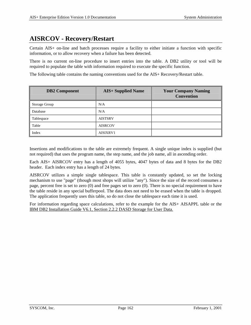
AIS+ Enterprise Edition Version 1.0 Documentation System Administration
SYSCOM, Inc. Page 162 February 1, 2001
AISRCOV - Recovery/Restart Certain AIS+ on-line and batch processes require a facility to either initiate a function with specific information, or to allow recovery when a failure has been detected.
There is no current on-line procedure to insert entries into the table. A DB2 utility or tool will be required to populate the table with information required to execute the specific function.
The following table contains the naming conventions used for the AIS+ Recovery/Restart table.
DB2 Component AIS+ Supplied Name Your Company Naming Convention
Storage Group N/A
Database N/A
Tablespace AISTSRV
Table AISRCOV
Index AISIXRV1
Insertions and modifications to the table are extremely frequent. A single unique index is supplied (but not required) that uses the program name, the step name, and the job name, all in ascending order.
Each AIS+ AISRCOV entry has a length of 4055 bytes, 4047 bytes of data and 8 bytes for the DB2 header. Each index entry has a length of 24 bytes.
AISRCOV utilizes a simple single tablespace. This table is constantly updated, so set the locking mechanism to use "page" (though most shops will utilize "any"). Since the size of the record consumes a page, percent free is set to zero (0) and free pages set to zero (0). There is no special requirement to have the table reside in any special bufferpool. The data does not need to be erased when the table is dropped. The application frequently uses this table, so do not close the tablespace each time it is used.
For information regarding space calculations, refer to the example for the AIS+ AISAPPL table or the IBM DB2 Installation Guide V6.1, Section 2.2.2 DASD Storage for User Data.

AIS+ Enterprise Edition Version 1.0 Documentation System Administration
SYSCOM, Inc. Page 163 February 1, 2001
The following tables reflect the aforementioned DB2 options required to build AIS+ AISRCOV.
Tablespace DDL Option Value Description
SEGSIZE N/A Simple tablespace does not use segments.
NUMPARTS N/A Simple tablespace does not use partitions.
LOCKSIZE PAGE or ANY The table is frequently updated where only 1 row fits to a page.
PRIQTY 48 See calculation above.
SECQTY 0 None required if primary quantity is set to carry all defined entries.
PCTFREE 0 The table is regularly updated, but space is not needed.
FREEPAGE 0 The table is regularly updated, but space is not needed.
BUFFERPOOL BP0 Most shops use bufferpool 0 for the majority of their work.
CLOSE NO Table is constantly being accessed.
ERASE NO The data in the table does not need to be erased whenever the table is dropped.
Index DDL Option Value Description
UNIQUE Index is unique.
RCOV_PROG_NAME (ASC)
RCOV_STEP_NAME (ASC)
RCOV_JOB_NAME (ASC)
PRIQTY 12 See calculation above.
SECQTY 0 None required if primary quantity is set to carry all defined entries.
PCTFREE 0 The table is regularly updated, but space is not needed.
FREEPAGE 0 The table is regularly updated, but space is not needed.
BUFFERPOOL BP0 Most shops use bufferpool 0 for the majority of their work.
CLOSE NO Table is constantly being accessed.
ERASE NO The data in the table does not need to be erased whenever the table is dropped.

AIS+ Enterprise Edition Version 1.0 Documentation System Administration
SYSCOM, Inc. Page 164 February 1, 2001
The following information describes the contents of an AIS+ AISRCOV data row:
Column Type & Length
Key Description
RCOV_PROG_NAME Char (8)
NNWD
1:1A Name of program requiring recovery/restart entry.
RCOV_STEP_NAME Char (8)
NNWD
1:2A Name of JCL step requiring recovery/restart entry.
RCOV_JOB_NAME Char (8)
NNWD
1:3A Name of job requiring recovery/restart entry.
RCOV_CNTL_FREQ Char (4)
NNWD
Function specific
RCOV_CNTL_INTERNAL Char (56)
NNWD
Function specific
RCOV_JOB_STATUS_CD Char (1)
NNWD
Function specific
RCOV_JOB_TERM_FL Char (1)
NNWD
Not used
RCOV_EFF_PEAK_TIME TIME
NNWD
Time of day that is classified as peak utilization, where resource utilization is a concern.
RCOV_PEAK_CMT_ROWS SMALLINT
NNWD
The number of rows that will be processed before a commit during peak time.
RCOV_PEAK_CMT_SECS SMALLINT
NNWD
Not used
RCOV_EFF_BTCH_TIME TIME
NNWD
Time of day that is not classified as peak utilization, where resource utilization is not a major concern.
RCOV_BAT_CMT_ROWS SMALLINT
NNWD
The number of rows that will be processed before a commit during non-peak time.
RCOV_BAT_CMT_SECS SMALLINT
NNWD
Not used
RCOV_EXCL_LOCK_FL Char (1)
NNWD
Not used
RCOV_START_TIME TIME
NNWD
Not used
RCOV_COMMIT_TIME TIME
NNWD
Not used
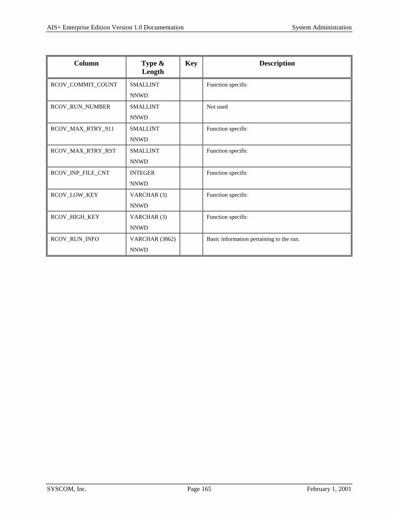
AIS+ Enterprise Edition Version 1.0 Documentation System Administration
SYSCOM, Inc. Page 165 February 1, 2001
Column Type & Length
Key Description
RCOV_COMMIT_COUNT SMALLINT
NNWD
Function specific
RCOV_RUN_NUMBER SMALLINT
NNWD
Not used
RCOV_MAX_RTRY_911 SMALLINT
NNWD
Function specific
RCOV_MAX_RTRY_RST SMALLINT
NNWD
Function specific
RCOV_INP_FILE_CNT INTEGER
NNWD
Function specific
RCOV_LOW_KEY VARCHAR (3)
NNWD
Function specific
RCOV_HIGH_KEY VARCHAR (3)
NNWD
Function specific
RCOV_RUN_INFO VARCHAR (3862)
NNWD
Basic information pertaining to the run.

AIS+ Enterprise Edition Version 1.0 Documentation System Administration
SYSCOM, Inc. Page 166 February 1, 2001
AISRLTT - RLOB/ Transaction Type Each routing line-of-business and transaction type combination associated with a category of work and user supplied parameters within an application must be defined to AIS+.
Entries in this table are generated through the use of the AIS+ RLOB/Tran Type Profile Administration function (AIS+ EE User Reference Manual).
The following table contains the naming conventions used for the AIS+ RLOB/Transaction Type table. AISRLTT is a view of the IBM FAF RLOB/Transaction Type table (EYPTWRTT).
DB2 Component AIS+ Supplied Name Your Company Naming Convention
Storage Group N/A
Database N/A
Tablespace EYPSWRTT
Table EYPTWRTT
Index EYPIWRTT1234CU
View AISRLTT
Insertions and modifications to the table are infrequent. One unique index is supplied (but not required) that uses the application ID, the routing line-of-business, the transaction type, and user parameter 1, all in ascending order.
Each AIS+ AISRLTT view entry has a length of 88 bytes, 80 bytes of data and 8 bytes for the DB2 header (the EYPTWRTT table actually has a length of 81 bytes). The index entry has a length of 18 bytes.
EYPTWRTT utilizes a simple single tablespace. Since this table is sparingly updated, the locking mechanism should be set to use the "tablespace" (though most shops will utilize "any"). Again, since insertion is possible (but not overly frequent), both percent free and free pages should both be set to zero (0). There is no special requirement to have the table reside in any special bufferpool. The data does not need to be erased when the table is dropped. This table is used frequently by the application, so the tablespace should not be closed each time it is used.
For information regarding space calculations, refer to the example for the AIS+ AISAPPL table or the IBM DB2 Installation Guide V6.1, Section 2.2.2 DASD Storage for User Data.

AIS+ Enterprise Edition Version 1.0 Documentation System Administration
SYSCOM, Inc. Page 167 February 1, 2001
The following table reflects the aforementioned DB2 options required to build FAF EYPTWRTT.
Tablespace DDL Option Value Description SEGSIZE N/A Simple tablespace does not use segments.
NUMPARTS N/A Simple tablespace does not use partitions.
LOCKSIZE TABLESPACE or ANY The table is rarely updated and is used extensively in a read-only fashion.
PRIQTY 12 See calculation above.
SECQTY 0 None required if primary quantity is set to carry all defined combinations.
PCTFREE 0 The table is rarely updated.
FREEPAGE 0 The table is rarely updated.
BUFFERPOOL BP0 Most shops use bufferpool 0 for the majority of their work.
CLOSE NO Table is constantly being accessed.
ERASE NO The data in the table does not need to be erased whenever the table is dropped.
Index DDL Option Value Description
UNIQUE Index is unique. APPLIDCD (ASC) RLOB (ASC) TRANTYPE (ASC) USERPRM1 (ASC)
PRIQTY 12 See calculation above.
SECQTY 0 None required if primary quantity is set to carry all defined combinations.
PCTFREE 0 The table is rarely updated.
FREEPAGE 0 The table is rarely updated.
BUFFERPOOL BP0 Most shops use bufferpool 0 for the majority of their work.
CLOSE NO Table is constantly being accessed.
ERASE NO The data in the table does not need to be erased whenever the table is dropped.
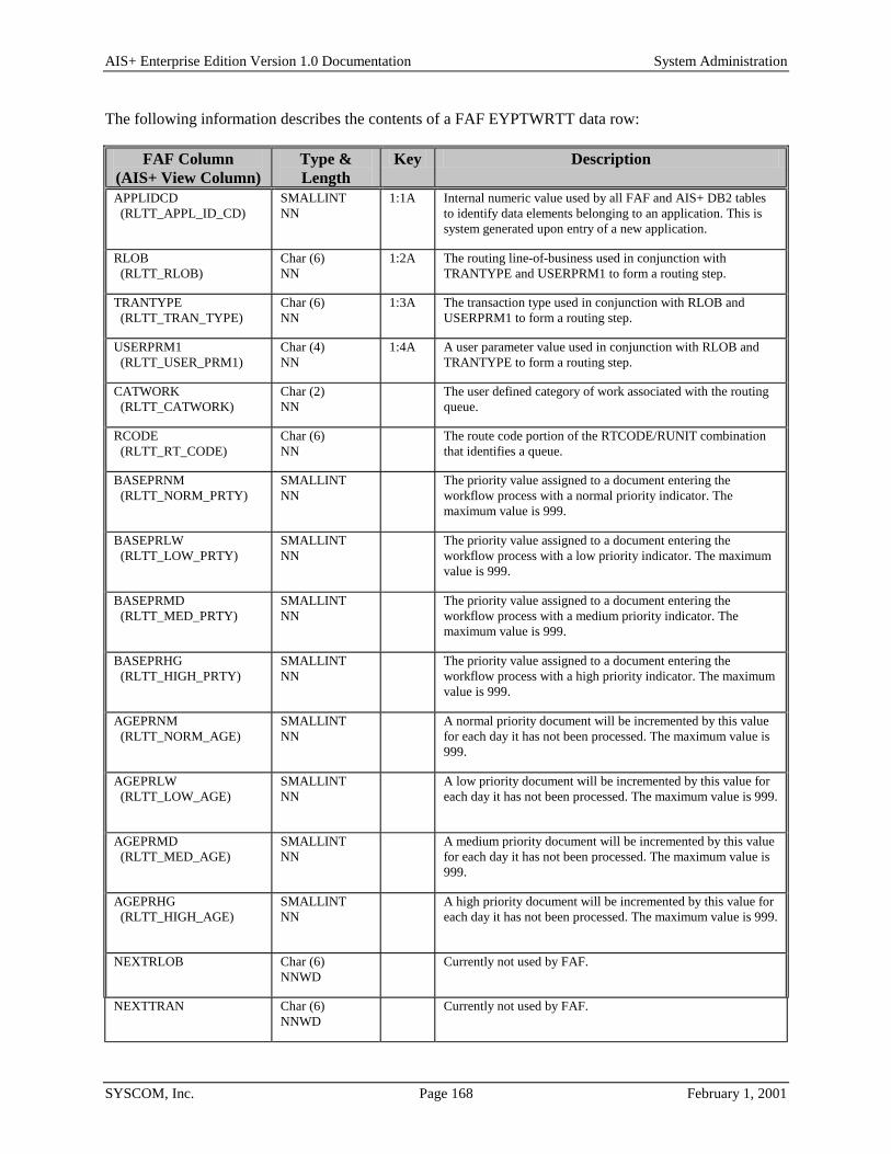
AIS+ Enterprise Edition Version 1.0 Documentation System Administration
SYSCOM, Inc. Page 168 February 1, 2001
The following information describes the contents of a FAF EYPTWRTT data row:
FAF Column (AIS+ View Column)
Type & Length
Key Description
APPLIDCD (RLTT_APPL_ID_CD)
SMALLINT NN
1:1A Internal numeric value used by all FAF and AIS+ DB2 tables to identify data elements belonging to an application. This is system generated upon entry of a new application.
RLOB (RLTT_RLOB)
Char (6) NN
1:2A The routing line-of-business used in conjunction with TRANTYPE and USERPRM1 to form a routing step.
TRANTYPE (RLTT_TRAN_TYPE)
Char (6) NN
1:3A The transaction type used in conjunction with RLOB and USERPRM1 to form a routing step.
USERPRM1 (RLTT_USER_PRM1)
Char (4) NN
1:4A A user parameter value used in conjunction with RLOB and TRANTYPE to form a routing step.
CATWORK (RLTT_CATWORK)
Char (2) NN
The user defined category of work associated with the routing queue.
RCODE (RLTT_RT_CODE)
Char (6) NN
The route code portion of the RTCODE/RUNIT combination that identifies a queue.
BASEPRNM (RLTT_NORM_PRTY)
SMALLINT NN
The priority value assigned to a document entering the workflow process with a normal priority indicator. The maximum value is 999.
BASEPRLW (RLTT_LOW_PRTY)
SMALLINT NN
The priority value assigned to a document entering the workflow process with a low priority indicator. The maximum value is 999.
BASEPRMD (RLTT_MED_PRTY)
SMALLINT NN
The priority value assigned to a document entering the workflow process with a medium priority indicator. The maximum value is 999.
BASEPRHG (RLTT_HIGH_PRTY)
SMALLINT NN
The priority value assigned to a document entering the workflow process with a high priority indicator. The maximum value is 999.
AGEPRNM (RLTT_NORM_AGE)
SMALLINT NN
A normal priority document will be incremented by this value for each day it has not been processed. The maximum value is 999.
AGEPRLW (RLTT_LOW_AGE)
SMALLINT NN
A low priority document will be incremented by this value for each day it has not been processed. The maximum value is 999.
AGEPRMD (RLTT_MED_AGE)
SMALLINT NN
A medium priority document will be incremented by this value for each day it has not been processed. The maximum value is 999.
AGEPRHG (RLTT_HIGH_AGE)
SMALLINT NN
A high priority document will be incremented by this value for each day it has not been processed. The maximum value is 999.
NEXTRLOB Char (6) NNWD
Currently not used by FAF.
NEXTTRAN Char (6) NNWD
Currently not used by FAF.

AIS+ Enterprise Edition Version 1.0 Documentation System Administration
SYSCOM, Inc. Page 169 February 1, 2001
FAF Column (AIS+ View Column)
Type & Length
Key Description
OPERFLAG Char (1) NNWD
Currently not used by FAF.
ASGNEMPL (RLTT_ASGN_EMP)
Char (8) NNWD
The operator ID that will be assigned all documents entering this workflow process for the first time.
MODUSER (RLTT_MODUSER)
Char (8) NNWD
The operator ID that performed the last update.
TIMECHGD (RLTT_MODTIME)
TIMESTAMP NNWD
The last date the queue description was modified.
AISSTATS - Operator Statistics The operator statistics report records the monthly statistics for each operator for a each month of the year, when the report is run. The entries that are not required can be deleted by the DB2 administrator.
Entries into this table are generated through the use of the AIS+ Operator Activity and Statistics Batch Report function (AIS+ Batch Reports Manual).
The following table contains the naming conventions used for the AIS+ Operator Statistics table.
DB2 Component AIS+ Supplied Name Your Company Naming Convention
Storage Group N/A
Database N/A
Tablespace AISTSTT
Table AISSTATS
Index AISIXSTATS1
Insertions and modifications to the table will take place every time the Operator Statistics and Activity Report is run. One unique index is supplied. The index uses the application ID, the Operator Name, the year_month, and the Route Unit all in ascending order.
Each AIS+ AISSTATS entry has a length of 100 bytes, 92 bytes of data and 8 bytes for the DB2 header. The index entry has a length of 21 bytes.
AISSTATS utilizes a simple single tablespace. If the table is rarely updated, the locking mechanism should be set to use the "tablespace" (though most shops will utilize "any"). There is no special requirement to have the table reside in any special bufferpool. The data does not need to be erased when the table is dropped.
For information regarding space calculations, refer to the example for the AIS+ AISAPPL table or the IBM DB2 Installation Guide V6.1, Section 2.2.2 DASD Storage for User Data.

AIS+ Enterprise Edition Version 1.0 Documentation System Administration
SYSCOM, Inc. Page 170 February 1, 2001
The following table reflects the aforementioned DB2 options required to build AIS+ AISSTATS.
Tablespace DDL Option
Value Description
SEGSIZE N/A Simple tablespace does not use segments.
NUMPARTS N/A Simple tablespace does not use partitions.
LOCKSIZE TABLESPACE or ANY The table will be extensively updated and inserted if the Operator Statistics Report is run frequently.
PRIQTY 5508 See calculation above.
SECQTY 2754 Can be set to 0, if the operator statistics report is not used.
PCTFREE 10 Can be set to 0, if the operator statistics report is not used.
FREEPAGE 0 Can be set to 0, if the operator statistics report is not used.
BUFFERPOOL BP0 Most shops use bufferpool 0 for the majority of their work.
CLOSE NO Table is constantly being accessed.
ERASE NO The data in the table does not need to be erased whenever the table is dropped.
Index 1 DDL Option
Value Description
UNIQUE Index is unique. STATS_APPLIDCD (ASC) STATS_USERID (ASC) STATS_YEAR_MNTH (ASC) STATS_RUNIT ( ASC)
PRIQTY 1408 See calculation above.
SECQTY 704 See calculation above.
PCTFREE 10 Can be set to 0, if the operator statistics report is not used.
FREEPAGE 0 Can be set to 0, if the operator statistics report is not used.
BUFFERPOOL BP0 Most shops use bufferpool 0 for the majority of their work.
CLOSE NO Table is constantly being accessed.

AIS+ Enterprise Edition Version 1.0 Documentation System Administration
SYSCOM, Inc. Page 171 February 1, 2001
Index 1 DDL Option
Value Description
ERASE NO The data in the table does not need to be erased whenever the table is dropped.
Column Type & Length Key Description STATS_APPLIDCD SMALLINT
NN 1:2A
Internal numeric value used by all FAF and AIS+ DB2 tables to identify data elements belonging to an application. This is system generated upon entry of a new application.
STATS_USERID Char (8) NN
3:8A The Userid derived from the AISOPPF table.
STATS_OPER_NAME Char(35) NN
The Oper Name is the formatted last name, middle initial, and first name of the Userid.
STATS_YEAR_MNTH Char (7) NN
46:7A The year and month for which the operator's statistics totals are stored. The format is CCYY-MM.
STATS_RUNIT Integer NN
53:4A The Route Unit associated with each User ID.
STATS_DOCS_WORK Integer NNWD
Total number of documents that the operator worked on in that month for a particular unit.
STATS_DOCS_ROUT Integer NNWD
Total number of documents that the operator routed in that month for a particular unit.
STATS_DOCS_HELD Integer NNWD
Total number of documents that the operator placed on hold in that month for a particular unit.
STATS_DOCS_STRT Integer NNWD
Total number of documents that the operator stored and routed in that month for a particular unit.
STATS_DOCS_NORT Integer NNWD
Total number of documents that the operator stored but did not route in that month for a particular unit.
STATS_DOCS_PRINT Integer NNWD
Total number of documents that the operator printed in that month for a particular unit.
STATS_PAGES_SCAN Integer NNWD
Total number of pages that the operator scanned in that month for a particular unit.
STATS_DOCS_INDEX Integer NNWD
Total number of documents that the operator indexed in that month for a particular unit.
STATS_DOCS_SCAN Integer NNWD
Total number of documents that the operator scanned in that month for a particular unit.

AIS+ Enterprise Edition Version 1.0 Documentation System Administration
SYSCOM, Inc. Page 172 February 1, 2001
AISTABS - Folder Tabs Each folder tab, for an individual application, that will be processed within the AIS+ software must be defined to the system.
Entries into this table are generated through the use of the AIS+ Folder Profile Administration function (AIS+ EE User Reference Manual).
The following table contains the naming conventions used for the AIS+ Folder Tab table.
DB2 Component AIS+ Supplied Name Your Company Naming Convention
Storage Group N/A
Database N/A
Tablespace AISTSTB
Table AISTABS
Index AISIXTB1 AISIXTB2
Insertions and modifications to the table are infrequent. Two unique indices are supplied (but not required). The first uses the application ID, the folder type, and the tab type all in ascending order. The second uses the application ID, the internal numeric folder type code, and the internal numeric tab code all in ascending order.
Each AIS+ AISTABS entry has a length of 34 bytes, 26 bytes of data and 8 bytes for the DB2 header. The first index entry has a length of 6 bytes and the second has a length of 6 bytes.
AISTABS utilizes a simple single tablespace. Since this table is rarely updated, the locking mechanism should be set to use the "tablespace" (though most shops will utilize "any"). Again, since insertion is rare, both percent free and free pages should both be set to zero (0). There is no special requirement to have the table reside in any special bufferpool. The data does not need to be erased when the table is dropped. This table is used frequently by the application, so the tablespace should not be closed each time it is used.
For information regarding space calculations, refer to the example for the AIS+ AISAPPL table or the IBM DB2 Installation Guide V6.1, Section 2.2.2 DASD Storage for User Data.

AIS+ Enterprise Edition Version 1.0 Documentation System Administration
SYSCOM, Inc. Page 173 February 1, 2001
The following table reflects the aforementioned DB2 options required to build AIS+ AISTABS.
Tablespace DDL Option
Value Description
SEGSIZE N/A Simple tablespace does not use segments.
NUMPARTS N/A Simple tablespace does not use partitions.
LOCKSIZE TABLESPACE or ANY The table is rarely updated and is used extensively in a read-only fashion.
PRIQTY 12 See calculation above.
SECQTY 0 None required if primary quantity is set to carry all defined combinations.
PCTFREE 0 The table is rarely updated.
FREEPAGE 0 The table is rarely updated.
BUFFERPOOL BP0 Most shops use bufferpool 0 for the majority of their work.
CLOSE NO Table is constantly being accessed.
ERASE NO The data in the table does not need to be erased whenever the table is dropped.
Index 1 DDL Option Value Description UNIQUE Index is unique.
TABS_APPLIDCD (ASC) TABS_FOLDTYPE (ASC) TABS_TABTYPE (ASC)
PRIQTY 12 See calculation above.
SECQTY 0 None required if primary quantity is set to carry all defined combinations.
PCTFREE 0 The table is rarely updated.
FREEPAGE 0 The table is rarely updated.
BUFFERPOOL BP0 Most shops use bufferpool 0 for the majority of their work.
CLOSE NO Table is constantly being accessed.
ERASE NO The data in the table does not need to be erased whenever the table is dropped.

AIS+ Enterprise Edition Version 1.0 Documentation System Administration
SYSCOM, Inc. Page 174 February 1, 2001
Index 2 DDL Option Value Description UNIQUE Index is unique.
TABS_APPLIDCD (ASC) TABS_FOLDTYCD (ASC) TABS_TABCD (ASC)
PRIQTY 12 See calculation above.
SECQTY 0 None required if primary quantity is set to carry all defined combinations.
PCTFREE 0 The table is rarely updated.
FREEPAGE 0 The table is rarely updated.
BUFFERPOOL BP0 Most shops use bufferpool 0 for the majority of their work.
CLOSE NO Table is constantly being accessed.
ERASE NO The data in the table does not need to be erased whenever the table is dropped.
The following information describes the contents of an AIS+ AISTABS data row:
Column Type & Length
Key Description
TABS_APPLIDCD SMALLINT NN
1:1A 2:1A
Internal numeric value used by all FAF and AIS+ DB2 tables to identify data elements belonging to an application. This is system generated upon entry of a new application.
TABS_FOLDTYCD SMALLINT NN
2:2A Internal numeric value used by all FAF and AIS+ tables to identify the folder type. This is system generated upon entry of a new folder type.
TABS_TABCD SMALLINT NN
2:3A Internal numeric value used by all FAF and AIS+ tables to identify the folder tab. This is system generated upon entry of a new folder/tab combination.
TABS_FOLDTYPE Char (2) NN
1:2A The type of folder. The type can be any two alphanumeric combination.
TABS_TABTYPE Char (2) NN
1:3A The tab acronym. The acronym can be any two alphanumeric combination.
TABS_DESCRIPTION Char (16) NN
The full length name or description of the tab.

AIS+ Enterprise Edition Version 1.0 Documentation System Administration
SYSCOM, Inc. Page 175 February 1, 2001
AISTRAN - CICS Transaction IDs Each CICS transaction used by AIS+ needs to be defined in the DB2 table. This allows for customers to customize the AIS+ transactions to best fit their environments. Customers may also define customer specific transactions to this table. These programs can then be initiated on any AIS+ panel that has a command line. Please call SYSCOM for more information if it is desired to implement this function.
There is no on-line facility to administer the CICS transaction customization. Modification can be performed through the use of either DB2 tools or utilities.
The following table contains the naming conventions used for the AIS+ CICS Transaction IDs table.
DB2 Component AIS+ Supplied Name Your Company Naming Convention
Storage Group N/A
Database N/A
Tablespace AISTSTR
Table AISTRAN
Index AISIXTR1, AISIXTR2
Insertions and modifications to the table are rare. Two unique indices are supplied (but not required). The first uses the application ID and the AIS+ transaction ID, both in ascending order. The second uses the application ID and the user's corresponding transaction ID.
Each AIS+ AISTRAN entry has a length of 19 bytes, 11 bytes of data and 8 bytes for the DB2 header. Each index entry has a length of 6 bytes.
AISTRAN utilizes a simple single tablespace. This table is rarely modified, so the locking mechanism should be set to use the "tablespace" (though most shops will utilize "any"). The percent free and free pages should both be set to zero (0). There is no special requirement to have the table reside in any special bufferpool. The data does not need to be erased when the table is dropped. This table is used frequently by the application, so the tablespace should not be closed each time it is used.
For information regarding space calculations, refer to the example for the AIS+ AISAPPL table or the IBM DB2 Installation Guide V6.1, Section 2.2.2 DASD Storage for User Data.

AIS+ Enterprise Edition Version 1.0 Documentation System Administration
SYSCOM, Inc. Page 176 February 1, 2001
The following table reflects the aforementioned DB2 options required to build AIS+ AISTRAN.
Tablespace DDL Option Value Description SEGSIZE N/A Simple tablespace does not use segments.
NUMPARTS N/A Simple tablespace does not use partitions.
LOCKSIZE TABLESPACE or ANY The table is rarely updated and is used extensively in a read-only fashion.
PRIQTY 12 See calculation above.
SECQTY 0 None required if primary quantity is set to carry all defined transactions.
PCTFREE 0 The table is rarely updated.
FREEPAGE 0 The table is rarely updated.
BUFFERPOOL BP0 Most shops use bufferpool 0 for the majority of their work.
CLOSE NO Table is constantly being accessed.
ERASE NO The data in the table does not need to be erased whenever the table is dropped.

AIS+ Enterprise Edition Version 1.0 Documentation System Administration
SYSCOM, Inc. Page 177 February 1, 2001
Index 1 DDL Option Value Description UNIQUE Index is unique.
TRAN_APPLIDCD (ASC) TRAN_AIS_TRAN (ASC)
PRIQTY 12 See calculation above.
SECQTY 0 None required if primary quantity is set to carry all defined transactions.
PCTFREE 0 The table is rarely updated.
FREEPAGE 0 The table is rarely updated.
BUFFERPOOL BP0 Most shops use bufferpool 0 for the majority of their work.
CLOSE NO Table is constantly being accessed.
ERASE NO The data in the table does not need to be erased whenever the table is dropped.
Index 2 DDL Option Value Description UNIQUE Index is unique.
TRAN_APPLIDCD (ASC) TRAN_USER_TRAN (ASC)
PRIQTY 12 See calculation above.
SECQTY 0 None required if primary quantity is set to carry all defined transactions.
PCTFREE 0 The table is rarely updated.
FREEPAGE 0 The table is rarely updated.
BUFFERPOOL BP0 Most shops use bufferpool 0 for the majority of their work.
CLOSE NO Table is constantly being accessed.
ERASE NO The data in the table does not need to be erased whenever the table is dropped.

AIS+ Enterprise Edition Version 1.0 Documentation System Administration
SYSCOM, Inc. Page 178 February 1, 2001
The following information describes the contents of an AIS+ AISTRAN data row:
Column Type & Length Key Description TRAN_APPLIDCD SMALLINT
NNWD 1:1A 2:1A
Internal numeric value used by all FAF and AIS+ DB2 tables to identify data elements belonging to an application.
TRAN_AIS_TRAN Char (4) NNWD
1:2A The AIS+ CICS native transaction ID.
TRAN_USER_TRAN Char (4) NNWD
2:2A The customized CICS transaction ID. If the CICS transactions are not customized, then they must match the native AIS+ transaction ID.
TRAN_INUSE_SW Char (1) NNWD
The on-line access switch indicates whether a user can enter the transaction ID in native CICS to access a function. Y - Yes, the transaction can be used in native CICS by a user to access the function. N - No, the transaction can not be used in native CICS by a user to access the function. C – Customer, the transaction calls a customer created program that is programmed to be started with data.
The current contents for a given application of the AISTRAN table should look as follows and should be entered into the table in sequence:
AISTRAN INUSE AISTRAN INUSE AISTRAN INUSE AISTRAN INUSE AOFF Y DC01 Y DC02 N DC03 N
DC04 N DC05 N DC06 Y DC07 N
DC08 N
FD01 Y FD02 Y FD03 Y FD04 Y
FD05 Y FD06 Y HP01 N MN01 Y
MN02 Y MN03 Y NT01 Y NT02 N
NT03 Y NT04 N NT05 N
RT01 N RT02 N
SA01 Y SA02 Y SA03 Y SA04 Y
SA05 Y SA06 Y SA09 N SA10 Y
SA11 Y SA12 Y SA13 Y SA14 Y
SO01 Y
UT01 N UT02 N UT03 N UT04 N
UT05 N UT06 N UT07 N UT08 N
WM01 Y WM02 Y WM03 Y WM04 Y
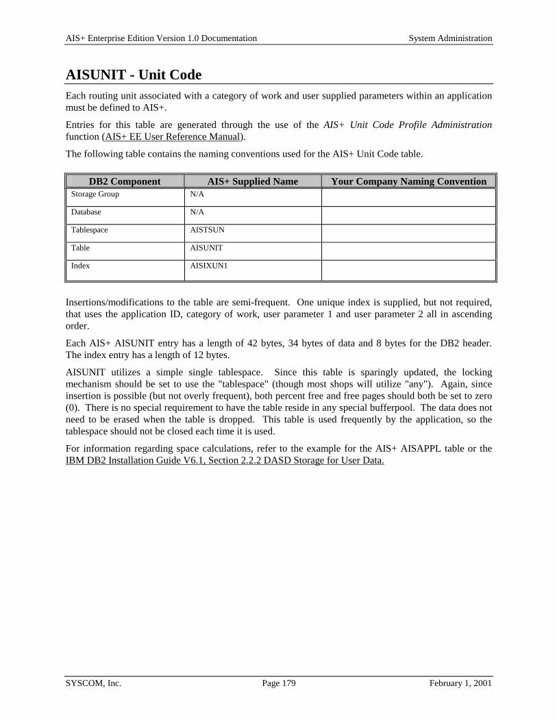
AIS+ Enterprise Edition Version 1.0 Documentation System Administration
SYSCOM, Inc. Page 179 February 1, 2001
AISUNIT - Unit Code Each routing unit associated with a category of work and user supplied parameters within an application must be defined to AIS+.
Entries for this table are generated through the use of the AIS+ Unit Code Profile Administration function (AIS+ EE User Reference Manual).
The following table contains the naming conventions used for the AIS+ Unit Code table.
DB2 Component AIS+ Supplied Name Your Company Naming Convention Storage Group N/A Database N/A Tablespace AISTSUN Table AISUNIT Index AISIXUN1
Insertions/modifications to the table are semi-frequent. One unique index is supplied, but not required, that uses the application ID, category of work, user parameter 1 and user parameter 2 all in ascending order.
Each AIS+ AISUNIT entry has a length of 42 bytes, 34 bytes of data and 8 bytes for the DB2 header. The index entry has a length of 12 bytes.
AISUNIT utilizes a simple single tablespace. Since this table is sparingly updated, the locking mechanism should be set to use the "tablespace" (though most shops will utilize "any"). Again, since insertion is possible (but not overly frequent), both percent free and free pages should both be set to zero (0). There is no special requirement to have the table reside in any special bufferpool. The data does not need to be erased when the table is dropped. This table is used frequently by the application, so the tablespace should not be closed each time it is used.
For information regarding space calculations, refer to the example for the AIS+ AISAPPL table or the IBM DB2 Installation Guide V6.1, Section 2.2.2 DASD Storage for User Data.

AIS+ Enterprise Edition Version 1.0 Documentation System Administration
SYSCOM, Inc. Page 180 February 1, 2001
The following table reflects the aforementioned DB2 options required to build AIS+ AISUNIT.
Tablespace DDL Option Value Description SEGSIZE N/A Simple tablespace does not use segments.
NUMPARTS N/A Simple tablespace does not use partitions.
LOCKSIZE TABLESPACE or ANY The table is rarely updated and is used extensively in a read-only fashion.
PRIQTY 12 See calculation above.
SECQTY 0 None required if primary quantity is set to carry all defined combinations.
PCTFREE 0 The table is rarely updated.
FREEPAGE 0 The table is rarely updated.
BUFFERPOOL BP0 Most shops use bufferpool 0 for the majority of their work.
CLOSE NO Table is constantly being accessed.
ERASE NO The data in the table does not need to be erased whenever the table is dropped.
Index DDL Option Value Description UNIQUE Index is unique.
UNIT_APPL_ID_CD (ASC) UNIT_CATWORK (ASC) UNIT_USER_PRM1 (ASC) UNIT_USER_PRM2 (ASC)
PRIQTY 12 See calculation above.
SECQTY 0 None required if primary quantity is set to carry all defined combinations.
PCTFREE 0 The table is rarely updated.
FREEPAGE 0 The table is rarely updated.
BUFFERPOOL BP0 Most shops use bufferpool 0 for the majority of their work.
CLOSE NO Table is constantly being accessed.
ERASE NO The data in the table does not need to be erased whenever the table is dropped.

AIS+ Enterprise Edition Version 1.0 Documentation System Administration
SYSCOM, Inc. Page 181 February 1, 2001
The following information describes the contents of an AIS+ AISUNIT data row:
Column Type & Length Key Description UNIT_APPL_ID_CD SMALLINT
NNWD 1:1A Internal numeric value used by all FAF and AIS+ DB2 tables
to identify data elements belonging to an application. This is system generated upon entry of a new application.
UNIT_CATWORK Char (2) NNWD
1:2A The user defined category of work associated with the routing queue.
UNIT_USER_PRM1 Char (4) NNWD
1:3A A user parameter value used in conjunction with RLOB and TRANTYPE to form a routing step.
UNIT_USER_PRM2 INTEGER NNWD
1:4A A user parameter value to further aid with routing step distinction.
UNIT_RT_UNIT INTEGER NNWD
The route unit portion of the RTCODE/RUNIT combination that identifies a queue.
UNIT_MODUSER Char (8) NNWD
The operator ID that performed the last update.
UNIT_MODTIME TIMESTAMP NNWD
The last date the queue description was modified.

AIS+ Enterprise Edition Version 1.0 Documentation System Administration
SYSCOM, Inc. Page 182 February 1, 2001
AISUNRC - Unit/Route Code Each routing queue consists of a routing unit and a route code. For each queue within an application, an entry must be defined to AIS+.
Entries are created for this table through the use of the AIS+ Unit/Route Code Profile Administration function (AIS+ EE User Reference Manual).
The following table contains the naming conventions used for the AIS+ Unit/Route Code table. AISUNRC is a view of the IBM FAF Unit/RCODE Queue Definition table (EYPTWURC).
DB2 Component AIS+ Supplied Name Your Company Naming Convention
Storage Group N/A
Database N/A
Tablespace EYPSWURC
Table EYPTWURC
Index EYPIWURC132CU
View AISUNRC
Insertions and modifications to the table are semi-frequent. One unique index is supplied (but not required) that uses the application ID, the route unit, and the route code all in ascending order.
Each FAF EYPTWURC data entry has a length of 90. The AIS+ AISUNRC view is 98 bytes, 90 bytes of data and 8 bytes for the DB2 header. The index entry has a length of 12 bytes.
EYPTWURC utilizes a simple single tablespace. Since this table is sparingly updated, the locking mechanism should be set to use the "tablespace" (though most shops will utilize "any"). Again, since insertion is possible (but not overly frequent), both percent free and free pages should both be set to zero (0). There is no special requirement to have the table reside in any special bufferpool. The data does not need to be erased when the table is dropped. This table is used frequently by the application, so the tablespace should not be closed each time it is used.
For information regarding space calculations, refer to the example for the AIS+ AISAPPL table or the IBM DB2 Installation Guide V6.1, Section 2.2.2 DASD Storage for User Data.

AIS+ Enterprise Edition Version 1.0 Documentation System Administration
SYSCOM, Inc. Page 183 February 1, 2001
The following table reflects the aforementioned DB2 options required to build FAF EYPTWURC.
Tablespace DDL Option Value Description SEGSIZE N/A Simple tablespace does not use segments.
NUMPARTS N/A Simple tablespace does not use partitions.
LOCKSIZE TABLESPACE or ANY The table is rarely updated and is used extensively in a read-only fashion.
PRIQTY 12 See calculation above.
SECQTY 0 None required if primary quantity is set to carry all defined combinations.
PCTFREE 0 The table is rarely updated.
FREEPAGE 0 The table is rarely updated.
BUFFERPOOL BP0 Most shops use bufferpool 0 for the majority of their work.
CLOSE NO Table is constantly being accessed.
ERASE NO The data in the table does not need to be erased whenever the table is dropped.
Index DDL Option Value Description UNIQUE Index is unique.
APPLIDCD (ASC) RUNIT (ASC) RCODE (ASC)
PRIQTY 12 See calculation above.
SECQTY 0 None required if primary quantity is set to carry all defined combinations.
PCTFREE 0 The table is rarely updated.
FREEPAGE 0 The table is rarely updated.
BUFFERPOOL BP0 Most shops use bufferpool 0 for the majority of their work.
CLOSE NO Table is constantly being accessed.
ERASE NO The data in the table does not need to be erased whenever the table is dropped.

AIS+ Enterprise Edition Version 1.0 Documentation System Administration
SYSCOM, Inc. Page 184 February 1, 2001
FAF Column
(AIS+ View Column) Type & Length Key Description
APPLIDCD (UNRC_APPL_ID_CD)
SMALLINT NN
1:1A Internal numeric value used by all FAF and AIS+ DB2 tables to identify data elements belonging to an application. This is system generated upon entry of a new application.
RCODE (UNRC_RT_CODE)
Char (6) NN
1:3A The route code portion of the RTCODE/RUNIT combination that identifies a queue.
RUNIT (UNRC_RT_UNIT)
INTEGER NN
1:2A The route unit portion of the RTCODE/RUNIT combination that identifies a queue.
WQUEDESC (UNRC_QUEDESC)
Char (60) NNWD
The full length name or description of the queue.
MODUSER (UNRC_MODUSER)
Char (8) NNWD
The operator ID that performed the last update.
TIMECHGD (UNRC_MODTIME)
TIMESTAMP NNWD
The last date the queue description was modified.

AIS+ Enterprise Edition Version 1.0 Documentation System Administration
SYSCOM, Inc. Page 185 February 1, 2001
AISWORK - Work Detail Each document that resides in routing resides in the Work Detail table. Of all the tables, this table is the most volatile! This is due to the volume of entries coming and going and changing directions (moving to other paths).
Entries to this table are created during an initial entry (AIS+ Document Index & Scan, AIS+ Document List, and AIS+ Document Modification), or modified as needed (AIS+ Work with Queued Items, AIS+ List Queue, and AIS+ Document Modification).
The following table contains the naming conventions used for the AIS+ Work Detail table. AISWORK is a view of the IBM FAF Work Detail table (EYPTWDET).
DB2 Component AIS+ Supplied Name Your Company Naming Convention
Storage Group N/A
Database N/A
Tablespace EYPSWDET
Table EYPTWDET
Index EYPID1101213U EYPID131213U AISIXWK4
View AISWORK
Insertions and modifications to the table are extremely frequent. Three indices are supplied. The first utilizes the application ID code, the folder token, the object timestamp, and the IODM create site, all in ascending order. The second index utilizes the application ID code, the routing unit, the object timestamp, and the IODM create site, all in ascending order. The third index utilizes the application ID code, the assigned employee ID, the routing unit, the routing code, the work indicator, the work priority, and the entry timestamp into work detail, all in ascending order (except priority which is in descending order).
Each AIS+ AISWORK view entry has a length of 210 bytes, 202 bytes of data and 8 bytes for the DB2 header (the EYPTWDET table actually has a length of 187 bytes). The index lengths are respectively 26 bytes, 20 bytes, and 33 bytes.
EYPTWDET utilizes a simple single tablespace. Since this table is constantly updated, the locking mechanism should be set to use "any". Insertion and modification are frequent. The percent free should be set at 80 and the free pages should be set at 5. The table would best reside in a special bufferpool (BP1 or BP2). The data does not need to be erased when the table is dropped. This table is used frequently by the application, so the tablespace should not be closed each time it is used.
For information regarding space calculations, refer to the example for the AIS+ AISAPPL table or the IBM DB2 Installation Guide V6.1, Section 2.2.2 DASD Storage for User Data.

AIS+ Enterprise Edition Version 1.0 Documentation System Administration
SYSCOM, Inc. Page 186 February 1, 2001
The following table reflects the aforementioned DB2 options required to build FAF EYPTWDET.
Tablespace DDL Option Value Description SEGSIZE N/A Simple tablespace does not use segments.
NUMPARTS N/A Simple tablespace does not use partitions.
LOCKSIZE ANY Due to the frequency of modification, it is best to let DB2 determine how to best utilize the locking methodology.
PRIQTY 3608 See calculation above.
SECQTY 1804 See calculation above.
PCTFREE 20 The table is frequently updated.
FREEPAGE 5 The table is frequently updated.
BUFFERPOOL BP1 or BP2 This table should be in its own buffer pool due to the nature of activity.
CLOSE NO Table is constantly being accessed.
ERASE NO The data in the table does not need to be erased whenever the table is dropped.
Index 1 DDL Option Value Description
UNIQUE Index is unique. APPLIDCD (ASC) FOLDTKN (ASC) OBJTIME (ASC) CRTESITE (ASC)
PRIQTY 500 See calculation above.
SECQTY 250 See calculation above.
PCTFREE 20 The table is frequently updated.
FREEPAGE 0 The table is frequently updated.
BUFFERPOOL BP0 Most shops use bufferpool 0 for the majority of their work.
CLOSE NO Table is constantly being accessed.
ERASE NO The data in the table does not need to be erased whenever the table is dropped.
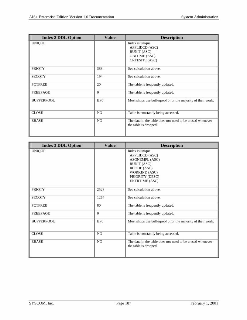
AIS+ Enterprise Edition Version 1.0 Documentation System Administration
SYSCOM, Inc. Page 187 February 1, 2001
Index 2 DDL Option Value Description
UNIQUE Index is unique. APPLIDCD (ASC) RUNIT (ASC) OBJTIME (ASC) CRTESITE (ASC)
PRIQTY 388 See calculation above.
SECQTY 194 See calculation above.
PCTFREE 20 The table is frequently updated.
FREEPAGE 0 The table is frequently updated.
BUFFERPOOL BP0 Most shops use bufferpool 0 for the majority of their work.
CLOSE NO Table is constantly being accessed.
ERASE NO The data in the table does not need to be erased whenever the table is dropped.
Index 3 DDL Option Value Description
UNIQUE Index is unique. APPLIDCD (ASC) ASGNEMPL (ASC) RUNIT (ASC) RCODE (ASC) WORKIND (ASC) PRIORITY (DESC) ENTRTIME (ASC)
PRIQTY 2528 See calculation above.
SECQTY 1264 See calculation above.
PCTFREE 80 The table is frequently updated.
FREEPAGE 0 The table is frequently updated.
BUFFERPOOL BP0 Most shops use bufferpool 0 for the majority of their work.
CLOSE NO Table is constantly being accessed.
ERASE NO The data in the table does not need to be erased whenever the table is dropped.

AIS+ Enterprise Edition Version 1.0 Documentation System Administration
SYSCOM, Inc. Page 188 February 1, 2001
The following information describes the contents of a FAF EYPTWDET data row:
Column Type & Length Key Description APPLIDCD (WORK_APPL_ID_CD)
SMALLINT NN
1:1A 2:1A 3:1A
Internal numeric value used by all FAF and AIS+ DB2 tables to identify data elements belonging to an application. This is system generated upon entry of a new application.
RCODE (WORK_RT_CODE)
Char (6) NN
3:4A The route code portion of the RTCODE/RUNIT combination that identifies a queue.
RUNIT (WORK_RUNIT)
INTEGER NN
2:2A 3:3A
The route unit portion of the RTCODE/RUNIT combination that identifies a queue.
RLOB (WORK_RLOB)
Char (6) NN
The routing line-of-business used in conjunction with TRANTYPE and USERPRM1 to form a routing step.
PRIORITY (WORK_PRIORITY)
SMALLINT NN
3:6D The priority level currently calculated for this document. The maximum is 999.
USERPRM1 (WORK_USER_PRM1)
Char (4) NN
A user parameter value used in conjunction with RLOB and TRANTYPE to form a routing step.
USERPRM2 (WORK_USER_PRM2)
INTEGER NN
A user parameter value to further aid with routing step distinction.
DOCNO SMALLINT NN
Currently not used by AIS+.
TRANTYPE (WORK_TRAN_TYPE)
Char (6) NN
The transaction type used in conjunction with RLOB and USERPRM1 to form a routing step.
FOLDTKN (WORK_FOLD_TKN)
TIMESTAMP NN
1:2A The unique internal timestamp generated by FAF to identify a folder.
RECVDATE (WORK_RECV_DATE)
DATE NN
The date specified as the document's receive date.
OBJTIME (WORK_OBJ_TIME)
TIMESTAMP NN
1:3A 2:3A
The unique internal timestamp generated by FAF to identify an object.
CRTESITE (WORK_CRTESITE)
Char (4) NN
1:4A 2:4A
The IODM symbolic name that originally stored the document into the system.
TIMECHGD (WORK_MODTIME)
TIMESTAMP NNWD
The date and time this record was last updated.
ASGNEMPL (WORK_ASGN_EMP)
Char (8) NN
3:2A The user ID of the individual assigned to process the document.
PROCEMPL (WORK_PROC_EMP)
Char (8) NN
The user ID of the individual who is processed the document.
HOLDDATE (WORK_HOLD_DATE)
DATE The document is suspended or held until the date specified.
HOLDTIME (WORK_HOLD_TIME)
TIME The document is suspended or held until the time on the date specified.

AIS+ Enterprise Edition Version 1.0 Documentation System Administration
SYSCOM, Inc. Page 189 February 1, 2001
Column Type & Length Key Description AGINGDTE (WORK_AGE_DATE)
DATE NN
The date from which aging is based. For each day passed, priority will be properly incremented; thus, allowing the document to rise to the top of the processing queue.
EXPRDATE (WORK_EXP_DATE)
DATE The date the document is to be removed from routing.
BASEPRIO (WORK_BASEPRIO)
SMALLINT NN
The base priority value assigned to the document based upon its current priority status.
AGEPRIO (WORK_AGEPRIO)
SMALLINT NN
The additional priority to be added to the base priority calculated from the elapsed days the document has resided within the queue.
OVERPIND (WORK_PRTY_IND)
Char (1) NN
The priority level currently assigned to the document. N - Normal L - Low M - Medium H - High X - Maximum
USERDET Char (40) NNWD
Not currently used by AIS+.
PREVEMP (WORK_PREV_EMP)
Char (8) NNWD
The previous user ID that accessed the document while processing it in its queue.
PREVUNIT (WORK_PREV_RUNIT)
INTEGER NNWD
The previous route unit that processed the document.
PREVCODE (WORK_PREV_RCODE)
Char (6) NNWD
The previous route code that processed the document.
WORKIND (WORK_WORK_IND)
Char (1) 3:5A The current status of the work detail entry. A - Available for processing H - On hold I - Inprocess (currently being worked by a user ID)
MODUSER (WORK_MODUSER)
Char (8) The user ID that last accessed or initiated this record.
ENTRTIME (WORK_ENTRY_TIME)
TIMESTAMP 3:7A The time in which the detail entry was created in the table.
USERDET (WORK-USERDET)
CHAR(40) User Details.
PREVRLOB (WORK-PREV-RLOB)
CHAR(6) The previous routing line of business (RLOB) that processed the document
PREVTRAN (WORK-PREV-TRANTYPE)
CHAR(6) The previous transaction type that processed the document.

AIS+ Enterprise Edition Version 1.0 Documentation System Administration
SYSCOM, Inc. Page 190 February 1, 2001
Appendix D: AIS+ Routing Overview This section provides an overview of the methods used to route documents in the AIS+ system. The AIS+ system uses a combination of DB2 tables and information which can be supplied in the Customer Data Exit. Tables: AISDCMT - This table is the AIS+ document or form control table. It defines the common attributes
of any document which is defined to the system using this form name. Two columns in this table are used to trigger routing of documents entered into the system via this form name. They are RLOB and TRAN TYPE (Routing line of business and Transaction type). The routing line of business is used to indicate the line of business which will be served by imaging application. The transaction type is used to indicate what type of processing will occur for a document indexed and scanned into the application.
AISRLTT - This table is the AIS+ routing line of business/transaction type table. The unique index into this table is application code, RLOB, TRANTYPE, and USERPRM1. RLOB and TRANTYPE were explained for the previous table, but USERPRM1 is a new variable in the whole routing scheme. This value must be supplied from the AIS+ customer data exit for Option code 1. If the value is not specified, then the column will default to spaces. For now, we will assume that no value has been supplied for the user parameter from the customer data exit. Later we will discuss the column in more detail.
This table is the routing driver of the system. From this table we retrieve the routing code and a category of work. These two fields are important because they will be used to query the other two routing tables to ultimately retrieve the unit to which work will be assigned. Three new variables have been introduced here, route code, category of work and unit code. Route code refers to an action that an operator will perform while working the document. Category of work is used in conjunction with the user parameter 1 mentioned above and another customer data exit variable, user parameter 2, to retrieve the unit code from the AISUNIT table to which work will be assigned. A unit code refers to a specific group, team, or department within an organization which is responsible for performing specific functions for specific documents or customers within the organization. All the variables mentioned above will be referenced again later.
AISUNIT - This is the AIS+ Unit Code table and is used to retrieve the appropriate team which will work the document. The index into this table is application code, category of work, user parameter 1 and user parameter 2. Remember from above that category of work was retrieved from the AISRLTT table and the user parameters were retrieved from the customer data exit. User parameter 1 will always default to spaces if no value is specified in the exit, and user parameter 2 will default to zero if no value is specified.
AISUNRC - This is the Unit Code/Route Code validation table. Once the route code is retrieved from the AISRLTT table, and the unit code is retrieved from the AISUNIT table, a query is made to this table to verify that the combination of the route code and unit code is valid. In addition, since AIS+ considers the two to be equal to a routing queue, a queue description is provided in the table.
AIS+ Enterprise Edition Version 1.0 Documentation System Administration
SYSCOM, Inc. Page 191 February 1, 2001
Examples: 1. In a simplified routing situation, document 1 would always go a data entry stop 1 and be worked by
team 1. For this case, no coding of the customer data exit for routing is necessary. Simply assure that there is an entry in the AISUNRC table for data entry stop 1 (call this route code 'ENTRY1') and team 1 (call this unit code '0001'). Additionally a AISUNIT entry must be made specifying unit code '0001' with the default user parameters (spaces and zero respectively) and a unique category of work (call this '01'). Next make sure there is an entry in the AISRLTT table which contains the RLOB and TranType specified in the AISDCMT table, the default user parameters (spaces and zero), the route code 'ENTRY1', and the category of work specified in the AISUNIT table.
In the above situation, routing of a specific type of document has been accomplished through the AIS+ system without any additional exit code having to be written.
2. Not all routing scenarios are as simple as the first one above. In this example, document 'A' will go to Team 1 if the folder (or customer) is from the western region of the country, and Team 2 if the folder is from the eastern region of the country. This is where user parameter 2 will become useful. In the customer data exit, you will need to specify 2 unique values to this field, one for each region of the country. Code can be written to interrogate the folder ID, query an external database or file, or look at other aspects of the document to determine which value will be propagated into the user parameter 2 field.
In the above situation, the only table which will need to have entries added is the AISUNIT table, since it is the only one which looks at the user parameter 2 value. All other values and table entries will stay the same. The AISUNIT table will contain two entries, both with the same user parameter 1 (spaces), and the same category of work ('01'). However there will be an entry for Team 1 (unit code '0001') and Team 2 (unit code '0002') and each of these rows will have a unique user parameter 2 value which will match what is being propagated in the customer data exit.
3. If a specific document type (document A) can have two different functions performed based upon the folder ID or some external information, then user parameter 1 becomes useful. In this situation, you would have two AISUNIT rows (each referring to team 1 or unit code '0001')) with default user parameter 2 values, category of work values of '01' and unique user parameter 1 values. The AISRLTT table would have two rows propagated into it, one would have a unique value for user parameter 1 pointing to category of work '01' and a route code of 'ENTRY1' while the second row would contain references to category of work '01' and route code 'ENTRY2'. This will accomplish routing the document to different functions within the same unit or team based on an external parameter.
The three previous examples only begin to show the power you have within your exits to create complex routing scenarios using both user parameter values. It is important to note that this logic is not only valuable for documents originally scanned into the system. You may have a secondary routing stop that you set up so that the operator routing the document does not have to know the specifics about what team or route code to send the document, but only the routing line of business and the type of transaction to be performed at the next routing step. With the addition of the Next RLOB and transaction type, The next routing stop for a document can be predetermined, requiring no action from the operator except to press a function key to route the documents.

AIS+ Enterprise Edition Version 1.0 Documentation System Administration
SYSCOM, Inc. Page 192 February 1, 2001
Appendix E: Customization Standards
Naming Standards
Exit Names The AIS+ provides the following Exits:
• AIEX001P - Customer Data Exit • AIEX002P - Validate Data Exit • AIEX003P - Routing Data Exit • AIEX004P - Storage Management Exit • AIEX005P - Security Exit • AIEX013P - Event Format Exit • AIEX015P – Pre-fetch Exit • AIEX016P - Field Edit Exit • AIEX017P - Object Deletion Exit • AIEX018P - Operator Administration Security Exit
• If your site uses only one application and there is no requirement to customize the Exits, you can install the Sample Exit Programs provided with AIS+ software.
• If your site needs to customize the exits for one application to combine specific business requirements with the AIS+ functions, the exit programs that are provided with the AIS+ software can be modified.
• If your site uses more than one application and each application requires a different set of Exits, you can copy the Exits into a different named member for each application. Each Exit Name should be given a unique Suffix character. The suffix character can be ‘0’ through ‘9’ and ‘A’ through ‘Z’. When adding an application to AIS+, the suffix assigned will need to be entered into the application profile setup. Below is a list of sample exits for a particular application. Figure 2 shows the application profile setup screen to add Application ‘AA’. Notice that the ‘Exit Name Suffix’ must be entered and must match the exit names created unless you are using the default exits shipped with the software.
• AIEX001N - Customer Data Exit • AIEX002N - Validate Data Exit • AIEX003N - Routing Data Exit • AIEX004N - Storage Management Exit • AIEX013N - Event Format Exit • AIEX015N - Prefetch Exit • AIEX016N - Field Edit Exit • AIEX017N - Object Deletion Exit • AIEX018N - Operator Administration Security Exit NOTE: The only valid name for the Security Exit is AIEX005P.

AIS+ Enterprise Edition Version 1.0 Documentation System Administration
SYSCOM, Inc. Page 193 February 1, 2001
APPLICATION PROFILE 1 ADD SA09 APPLICATION CODE: 26 ID: AA TABLESET: 7 DESCRIPTION: MORTGAGE APPLICATION CREATE SITE: ODMP COLLECTION: EYP.COLLCT0 AVAILABLE APPLICATION CODES ARE: , , , , , , , , , , , , , , , , , , , , , , , , , ,26,27,28,29,30,31,32,33,34,35,36,37,38,39,40,41,42,43,44,45,46,47,48,49, 50,51,52,53,54,55,56,57,58,59,60,61,62,63,64,65,66,67,68,69,70,71,72,73, , 75,76,77,78,79,80,81,82,83,84,85,86,87,88,89,90,91,92,93,94,95,96,97,98,99 DATE FORMAT: 1 TIME DISPLAY FORMAT: 1 1=MM/DD/YYYY 2=DD/MM/YYYY 3=DD.MM.YYYY TIME ENTRY FORMAT: 1 4=YYYY-MM-DD 5=DD-MM-YYYY 6=DD MM YYYY 1=12 HR 2=24 HR DOCUMENT LIST FORMAT: 1 FOLDER TAB LIST FORMAT: T NUMBER OF WORK ITEMS: 99 (1-30 CHAR, 2-60 CHAR) SORT WORK ITEMS : P SYSTEM ADMINISTRATOR ID: SYSCOM SYSTEM ADMINISTRATOR PW: SYSCOM TEMP ID TYPE: 3 TEMP ID PREFIX: _ FOLDER TYPE PREFIX (Y,N): N COPY IND (L,C): L DELETE IND (L,C): L MAX DAYS: 060 FUTR DAYS: 030 EXIT NAME SUFFIX: P MAP NAME SUFFIX: M MAXIMUM PRIORITY: 951 PF 3=EXIT 5=ADD 12=CANCEL
Figure 2 – Entering Exit Name Suffix During Application Profile Creation

AIS+ Enterprise Edition Version 1.0 Documentation System Administration
SYSCOM, Inc. Page 194 February 1, 2001
Map Names A Map is text that is displayed on your computer screen and is organized in a consistent manner. The text and its organization depend on the function of the map.
• If your site uses only one application and there is no need to customize the maps, you can install the maps as they are provided with AIS+.
• If your site uses only one application but there is a requirement to customize the maps, the maps provided with AIS+ may be customized.
• If your site uses more than one application and each application requires a different set of maps, you can copy the maps into a different named member for each application. Each Map Name, except the sign-on maps (AISO01M and AIMN01M) should be given a unique Suffix character. The suffix character can be ‘0’ through ‘9’ and ‘A’ through ‘Z’. When adding an application to AIS+, the suffix assigned will need to be entered into the application profile setup. Figure 3 shows the application profile setup screen to add Application ‘AA’. Notice that the ‘Map Name Suffix’ must be entered and must match the map names created unless you are using the defaults shipped with the software. The following is an example of the main menu map name as it is shipped and customized for suffix “B”:
As shipped: AIMN02M Customized: AIMN02B. APPLICATION PROFILE 1 ADD SA09 APPLICATION CODE: 26 ID: AA TABLESET: 7 DESCRIPTION: MORTGAGE APPLICATION CREATE SITE: ODMP COLLECTION: EYP.COLLCT0 AVAILABLE APPLICATION CODES ARE: , , , , , , , , , , , , , , , , , , , , , , , , , ,26,27,28,29,30,31,32,33,34,35,36,37,38,39,40,41,42,43,44,45,46,47,48,49, 50,51,52,53,54,55,56,57,58,59,60,61,62,63,64,65,66,67,68,69,70,71,72,73, , 75,76,77,78,79,80,81,82,83,84,85,86,87,88,89,90,91,92,93,94,95,96,97,98,99 DATE FORMAT: 1 TIME DISPLAY FORMAT: 1 1=MM/DD/YYYY 2=DD/MM/YYYY 3=DD.MM.YYYY TIME ENTRY FORMAT: 1 4=YYYY-MM-DD 5=DD-MM-YYYY 6=DD MM YYYY 1=12 HR 2=24 HR DOCUMENT LIST FORMAT: 1 FOLDER TAB LIST FORMAT: T NUMBER OF WORK ITEMS: 99 (1-30 CHAR, 2-60 CHAR) SORT WORK ITEMS : P SYSTEM ADMINISTRATOR ID: SYSCOM SYSTEM ADMINISTRATOR PW: SYSCOM TEMP ID TYPE: 3 TEMP ID PREFIX: _ FOLDER TYPE PREFIX (Y,N): N COPY IND (L,C): L DELETE IND (L,C): L MAX DAYS: 060 FUTR DAYS: 030 EXIT NAME SUFFIX: P MAP NAME SUFFIX: M MAXIMUM PRIORITY: 951 PF 3=EXIT 5=ADD 12=CANCEL
Figure 3 – Entering Map Name Suffix During Application Profile Creation

AIS+ Enterprise Edition Version 1.0 Documentation System Administration
SYSCOM, Inc. Page 195 February 1, 2001
Basic Rules for Customizing Maps When customizing the maps, the following is acceptable:
• Change the title of any map • Change any hard-coded text on the map, including instructional text and field names
The following sign-on map names cannot be given a unique suffix other than ‘M’: • AISO01M • AIMN01M
The following restrictions apply when customizing the maps: • Do not change the order of the fields on a map • Do not change the field format (field type) or length • Do not add or delete fields

AIS+ Enterprise Edition Version 1.0 Documentation System Administration
SYSCOM, Inc. Page 196 February 1, 2001
Transaction Names The AIS+ software is delivered with the default transaction names for each function. These transaction names can be customized for each application in AIS+. The table AISTRAN consists of all the transaction names for each application. When a new application is created, the AISTRAN table must be updated to incorporate all the transaction names for that application. The AISTRAN table consists of the following fields:
Column Type & Length
Description
TRAN_APPLIDCD Small Integer The Application code number assigned to each application. The Application code number for the application created can be determined by listing the AISAPPL table.
TRAN_AIS_TRAN Char (4) The AIS+ native transaction name.
Note: The values in this field must not be changed.
TRAN_USER_TRAN Char (4) You may change the value in this field to a customized transaction name. The customized transaction name must not be repeated within the same application. These transaction names must be entered in the proper CICS tables.
TRAN_INUSE_SW Char (1) Indicates whether the transaction can be entered from native CICS screen.
Note: The value in this field must not be changed.