version: 1.4 - - vcp can ... launching the wabco programming add-on 52 5.3.3 wabco –...
TRANSCRIPT
Handbook
VCP System - Professional Diagnostic Tool
for VW AG. Cars
Version: 1.4.2
For all VCP Diagnostic Interfaces:
VCP SYSTEM interface v2.0 New Generation (Hardware version v2.0)
VCP SYSTEM with a separate Dongle (Hardware version v1.0)
© Copyright | vcpsystem.com
Last Update: 18.05.2017
This Handbook was created by vcpsystem.com and cannot be distributed or resold to third
parties and without prior consent. Publishing this document or contents / parts thereof is also
not permitted without prior consent.
Thank you very much
1 Table of Contents 1 Basic Installation of VCP SYSTEM and Driver Installation .............................................. 6
1.1 Basic Installation ......................................................................................................... 6
1.2 Driver Installation ........................................................................................................ 8
1.3 Device Driver Installation ......................................................................................... 12
2 Initial Configuration and Smart Card Activation via VCP Activator ............................... 13
2.1 About VCP ACTIVATOR ........................................................................................ 13
2.2 VCP ACTIVATOR Update ....................................................................................... 14
2.3 Activation of VCP and Program Parts Download ..................................................... 16
2.4 Language Settings in ACTIVATOR ......................................................................... 19
2.5 Cannot connect with the server - not authorized to connect ...................................... 20
2.6 No connection to server – no connection / response from the server ....................... 21
2.7 Update firmware version of the VCP Diagnostic Interface ....................................... 22
2.7.1 Upgrade to VCP System + K-Line Interface.................................................................... 22
2.8 Update renewal - Subscription Status ........................................................................ 23
3 Basic Information about this Software ............................................................................. 24
3.1 ECUs Details page - more ECUs ............................................................................... 25
3.2 Diagnosis Sessions .................................................................................................... 25
4 VCP Initial Configuration ................................................................................................. 27
4.1 Language settings ...................................................................................................... 28
4.2 Select Log Path .......................................................................................................... 29
4.3 Automatic Communication Establishment for ECUs ................................................ 29
4.4 VCP Skin - Adjust the Interface ................................................................................ 30
4.4.1 Skin Preview .................................................................................................................. 31
4.5 ECU favourites editor (v 8.0.3+) .............................................................................. 32
5 OCF – One Click Functions .............................................................................................. 34
5.1 OCF - ZDC-Container - Data Upload Assistant for Parameter Settings ................... 34
5.1.1 ZDC Container Files Management (File Management) ................................................. 34
5.1.2 Practical example; VIM activation with ZDC Container File .......................................... 38
5.1.3 ZDC Container Files Configuration – Local Storage ....................................................... 44
5.2 OCF – VIM Manager ................................................................................................ 46
5.2.1 VIM Manager – currently supported vehicles / Infotainment ECUs ............................. 46
5.2.2 VIM Manager – Procedures ........................................................................................... 47
5.3 OCF - WABCO Programmer .................................................................................... 52
5.3.1 WABCO - currently supported vehicles ......................................................................... 52
5.3.2 Launching the WABCO Programming Add-on ............................................................... 52
5.3.3 WABCO – Configuration options ................................................................................... 54
5.4 OCF – PRCoding ....................................................................................................... 55
5.4.1 Procedure ...................................................................................................................... 55
5.5 OCF – Start/Stop deactivation ................................................................................... 56
5.5.1 Start/Stop deactivation - supported vehicles ................................................................ 56
5.5.2 Start/Stop deactivation - procedure ............................................................................. 56
5.6 OCF – ESP deactivation ............................................................................................ 61
5.6.1 ESP deactivation - supported vehicles ........................................................................... 61
5.6.2 ESP deactivation - procedure ........................................................................................ 61
5.7 OCF - Battery coding for battery manager ................................................................ 64
5.8 OCF - lock/unlock Electronic Handbrake ................................................................. 65
5.8.1 Supported vehicles ........................................................................................................ 65
5.8.2 Procedure ...................................................................................................................... 66
5.9 OCF – deactivate Passenger Air bag ......................................................................... 67
5.10 OCF – Headlamp Beam Height Control ................................................................ 69
5.10.1 Supported vehicles ........................................................................................................ 69
5.10.2 Procedure ...................................................................................................................... 69
5.11 OCF – DPF Emergency Regeneration ................................................................... 71
5.11.1 Supported vehicles ........................................................................................................ 71
5.12 OCF – DPF Inspection 2.0 TDI / 2.7 – 3.0 TDI .................................................... 73
5.13 OCF – DPF Adjustments after replacement 2.0/2.7/3.0 TDI | Crafter .................. 75
5.13.1 Supported vehicles / motors ......................................................................................... 75
5.14 OCF – BCM PQx5 Programming (Golf, Polo, Ibiza etc.) ..................................... 78
5.14.1 Supported vehicles ........................................................................................................ 78
5.14.2 Procedure ...................................................................................................................... 78
5.15 OCF – programming characteristics of the Power Assisted Steering control device
(Golf 6, Passat,..) .................................................................................................................. 79
5.15.1 Supported vehicles ........................................................................................................ 79
5.15.2 Procedure ...................................................................................................................... 80
5.16 OCF – Acceleration Measurements ....................................................................... 81
5.16.1 Supported vehicles ........................................................................................................ 81
5.16.2 Procedure ...................................................................................................................... 82
5.17 OCF – VIM / TV regional lockdown removal for MMI 2G/3G/3GP models. ...... 83
5.17.1 Supported vehicles ........................................................................................................ 83
5.17.2 Procedure ...................................................................................................................... 84
5.18 OCF – reading Immobilizer PIN EDC15P EDC16 ............................................... 84
5.18.1 Supported vehicles ........................................................................................................ 84
5.18.2 Procedure ...................................................................................................................... 85
5.19 OCF – DSG Parameters adjustments ..................................................................... 86
5.19.1 Supported vehicles ........................................................................................................ 86
5.19.2 Procedure ...................................................................................................................... 86
5.20 OCF – Activating wing mirror folding in UDS Door Control Units ..................... 87
5.20.1 Supported vehicles ........................................................................................................ 87
5.20.2 Procedure ...................................................................................................................... 88
6 Auto-Scanner (Fault Memory Reading) ........................................................................... 91
7 Gateway – Part list ............................................................................................................ 93
8 ECU Flasher ...................................................................................................................... 93
8.1 Supported vehicles ..................................................................................................... 93
8.2 Supported File Types ................................................................................................. 93
8.3 Procedure ................................................................................................................... 94
9 Multiflasher ....................................................................................................................... 95
9.1 Procedure ................................................................................................................... 96
10 EEPROM read/write ......................................................................................................... 97
10.1 Supported vehicles ................................................................................................. 97
10.2 Procedure ............................................................................................................... 97
11 Login Finder .................................................................................................................... 100
12 VCP Scripter ................................................................................................................... 101
13 VCP Flash Dumper ......................................................................................................... 102
14 Sample coding ................................................................................................................. 106
14.1 Audi A3 8V or MQB Platform – Activating the visual display of the Parking
Assist System. .................................................................................................................... 106
14.1.1 ECU (STG) 10 – connecting the Parking Assist System ................................................ 106
14.1.2 Security Access ............................................................................................................ 109
14.1.3 Coding procedure ........................................................................................................ 111
14.2 Audi A3 8V or MQB Platform – Fuel consumption adjustments ....................... 112
14.2.1 ECU (STG) 17 – connecting the switchboard ............................................................... 113
14.2.2 Perform the adjustments ............................................................................................ 113
15 Problems / Troubleshooting ............................................................................................ 115
15.1 Activator cannot start ........................................................................................... 115
15.2 Cannot find FTD2XX.DLL - encountered after initial installation [Generation v1.0
] 115
15.3 cannot find nn.dll please re-install – encountered after initial installation /
configuration [v1.0 & v2.0] ................................................................................................ 115
15.4 When launching VCP: Interface not found .......................................................... 116

15.5 When launching VCP: Smart Card not found ...................................................... 116
1 Basic Installation of VCP SYSTEM and Driver Installation
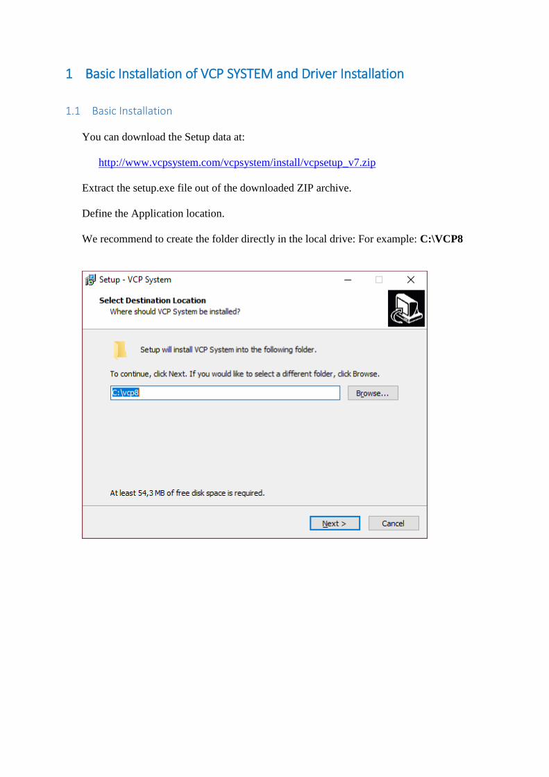
1.1 Basic Installation
You can download the Setup data at:
http://www.vcpsystem.com/vcpsystem/install/vcpsetup_v7.zip
Extract the setup.exe file out of the downloaded ZIP archive.
Define the Application location.
We recommend to create the folder directly in the local drive: For example: C:\VCP8
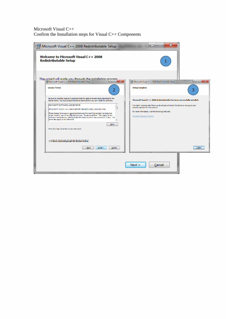
Microsoft Visual C++
Confirm the Installation steps for Visual C++ Components
1
2 3
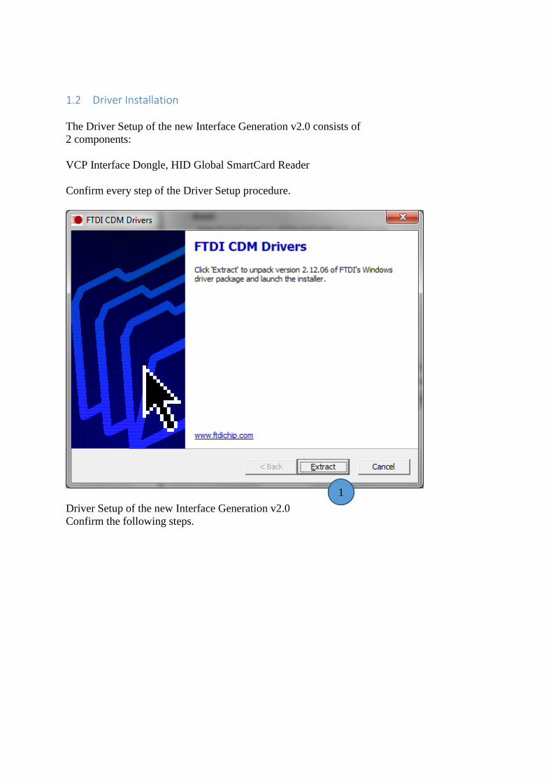
1.2 Driver Installation
The Driver Setup of the new Interface Generation v2.0 consists of
2 components:
VCP Interface Dongle, HID Global SmartCard Reader
Confirm every step of the Driver Setup procedure.
Driver Setup of the new Interface Generation v2.0
Confirm the following steps.
1
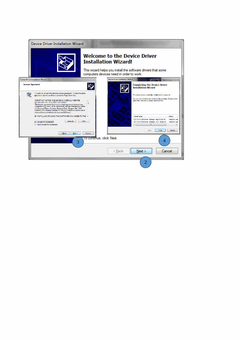
2
3 4
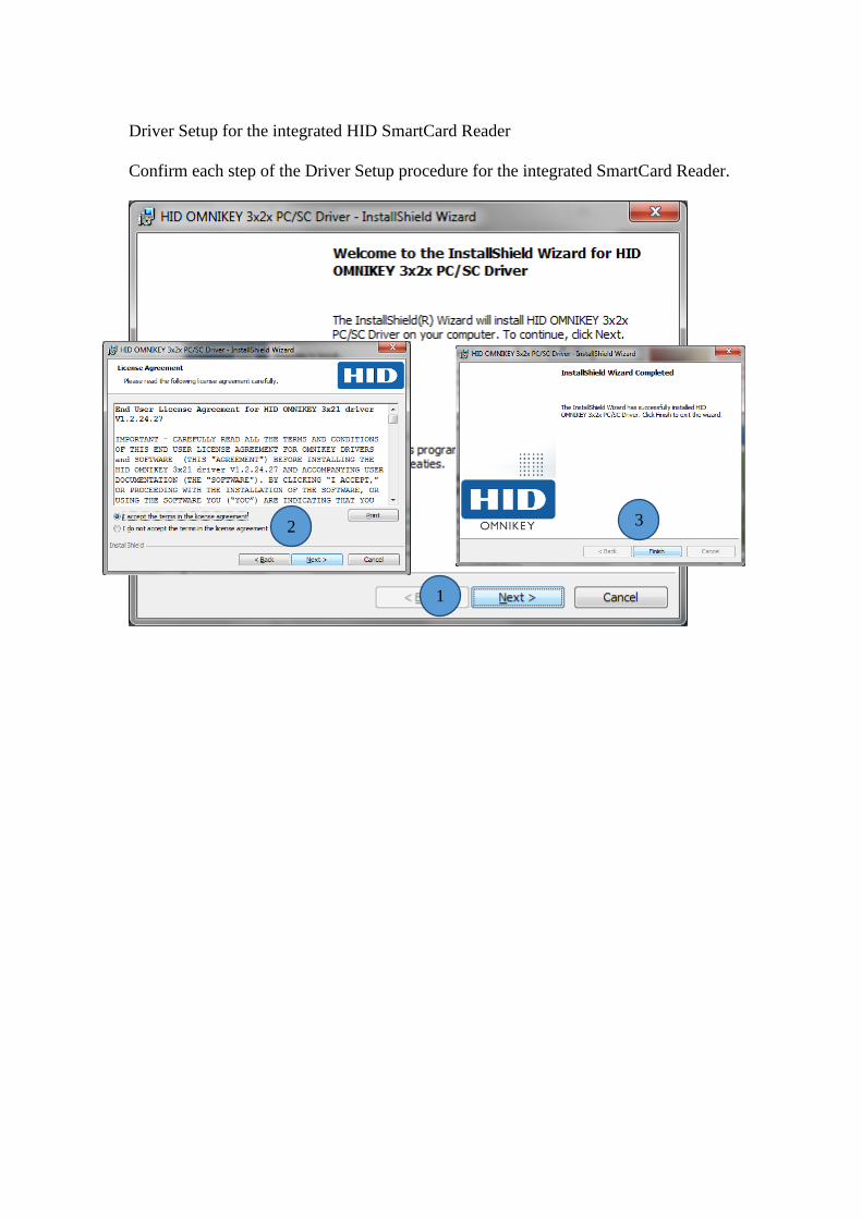
Driver Setup for the integrated HID SmartCard Reader
Confirm each step of the Driver Setup procedure for the integrated SmartCard Reader.
1
2 3
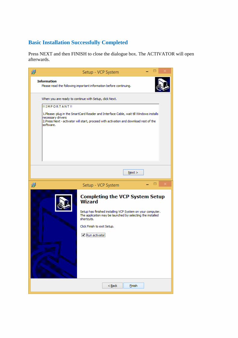
Basic Installation Successfully Completed
Press NEXT and then FINISH to close the dialogue box. The ACTIVATOR will open
afterwards.
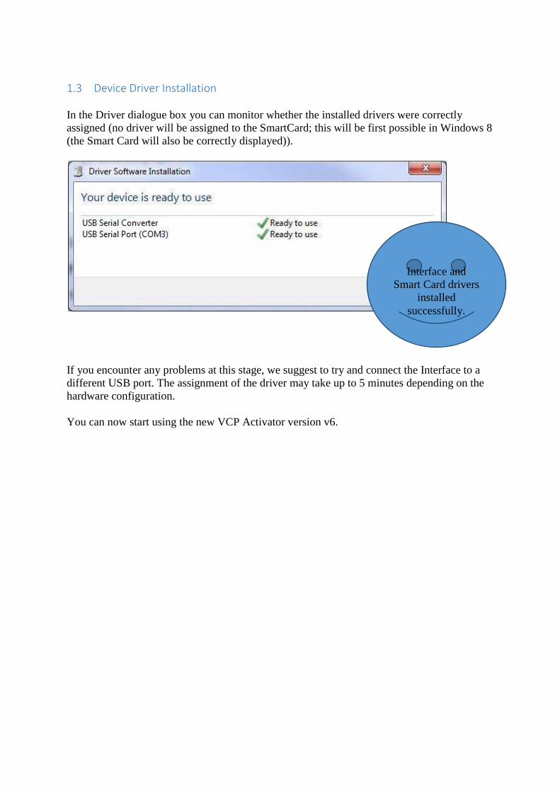
1.3 Device Driver Installation
In the Driver dialogue box you can monitor whether the installed drivers were correctly
assigned (no driver will be assigned to the SmartCard; this will be first possible in Windows 8
(the Smart Card will also be correctly displayed)).
If you encounter any problems at this stage, we suggest to try and connect the Interface to a
different USB port. The assignment of the driver may take up to 5 minutes depending on the
hardware configuration.
You can now start using the new VCP Activator version v6.
Interface and
Smart Card drivers
installed
successfully.
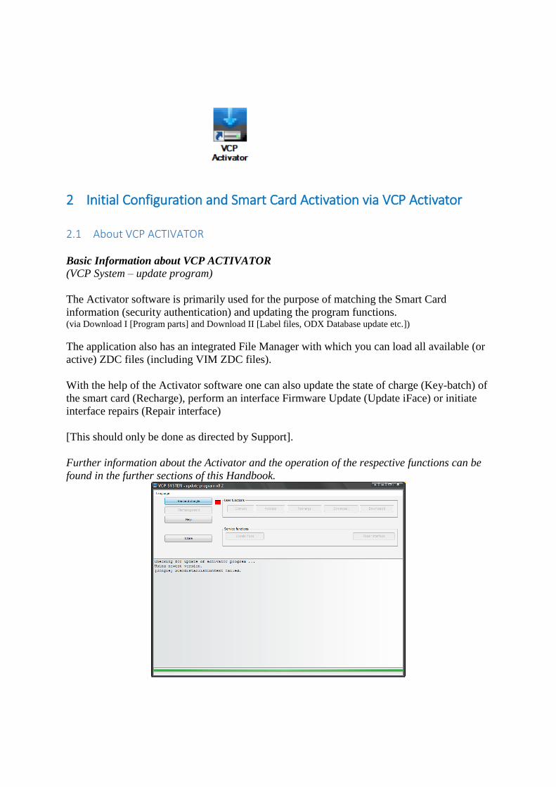
2 Initial Configuration and Smart Card Activation via VCP Activator
2.1 About VCP ACTIVATOR
Basic Information about VCP ACTIVATOR
(VCP System – update program)
The Activator software is primarily used for the purpose of matching the Smart Card
information (security authentication) and updating the program functions. (via Download I [Program parts] and Download II [Label files, ODX Database update etc.])
The application also has an integrated File Manager with which you can load all available (or
active) ZDC files (including VIM ZDC files).
With the help of the Activator software one can also update the state of charge (Key-batch) of
the smart card (Recharge), perform an interface Firmware Update (Update iFace) or initiate
interface repairs (Repair interface)
[This should only be done as directed by Support].
Further information about the Activator and the operation of the respective functions can be
found in the further sections of this Handbook.
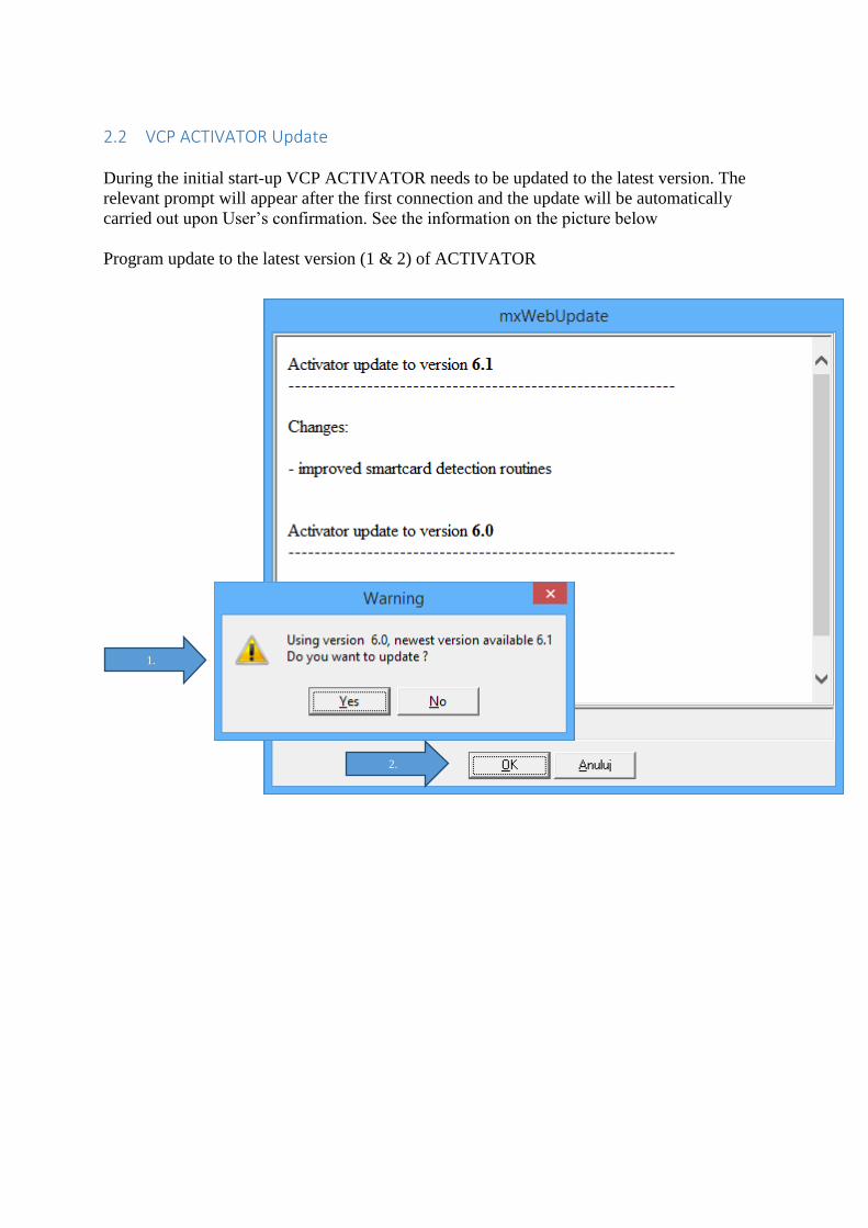
2.2 VCP ACTIVATOR Update
During the initial start-up VCP ACTIVATOR needs to be updated to the latest version. The
relevant prompt will appear after the first connection and the update will be automatically
carried out upon User’s confirmation. See the information on the picture below
Program update to the latest version (1 & 2) of ACTIVATOR
2.
1.
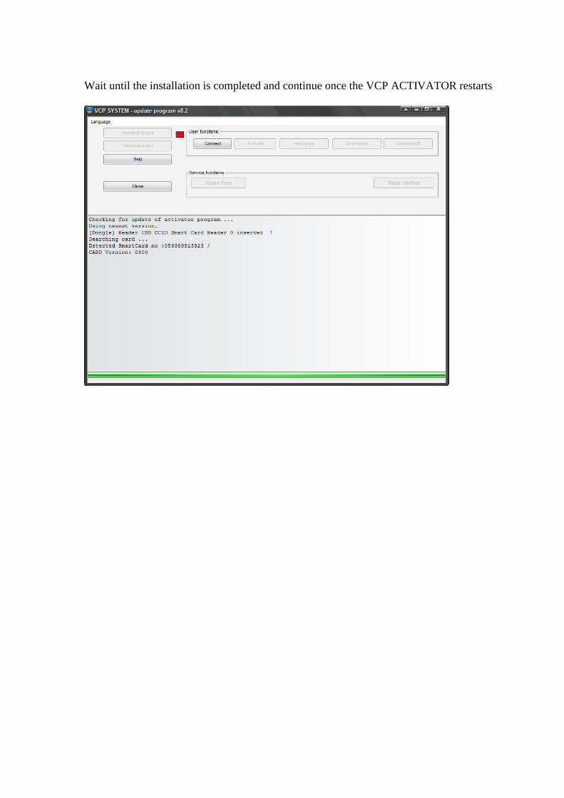
Wait until the installation is completed and continue once the VCP ACTIVATOR restarts
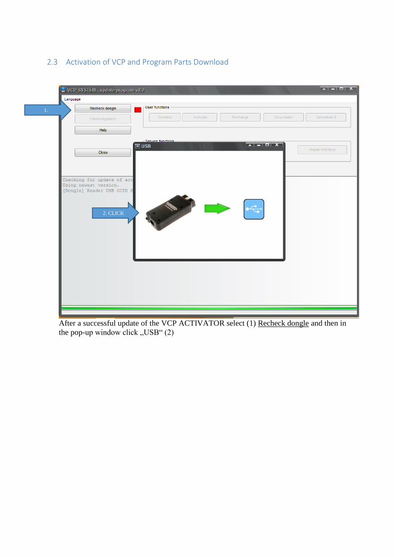
2.3 Activation of VCP and Program Parts Download
After a successful update of the VCP ACTIVATOR select (1) Recheck dongle and then in
the pop-up window click „USB“ (2)
1.
2. CLICK
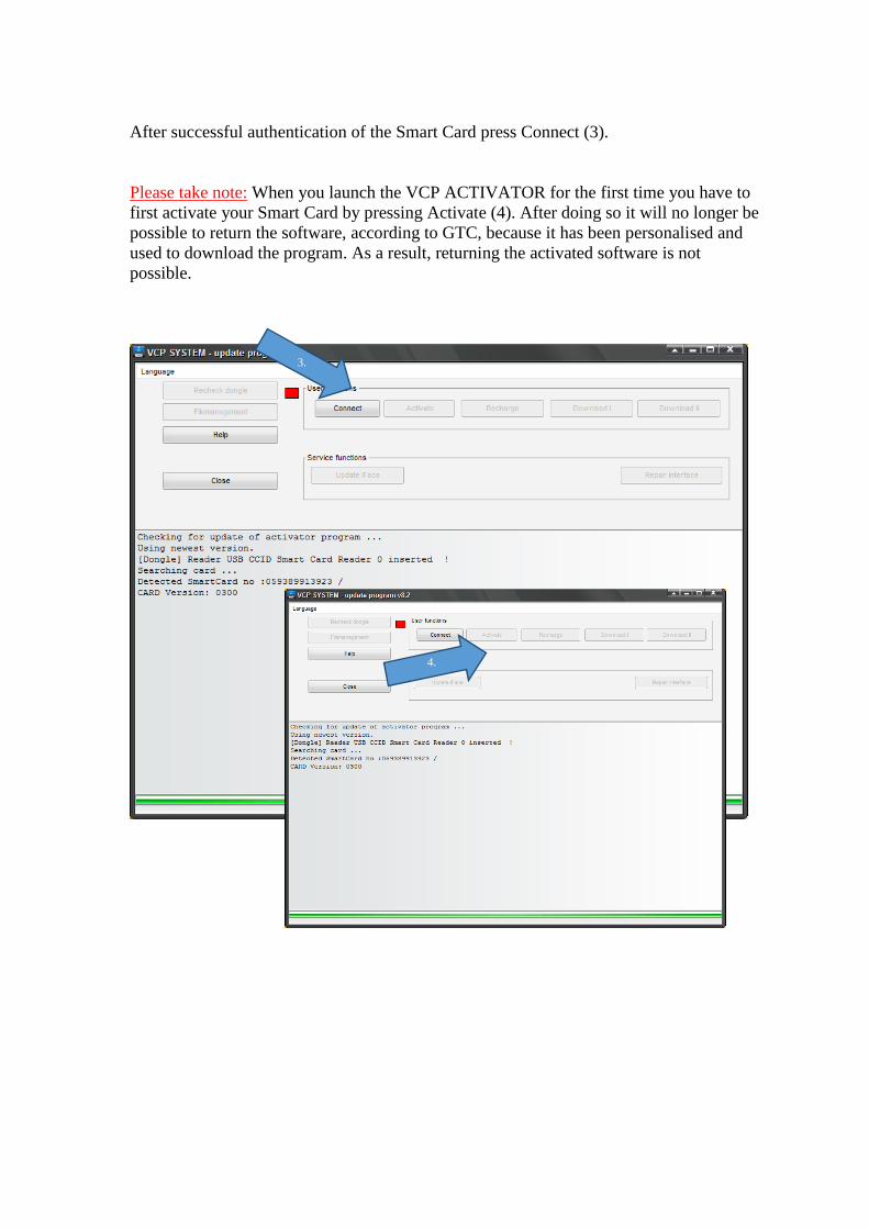
After successful authentication of the Smart Card press Connect (3).
Please take note: When you launch the VCP ACTIVATOR for the first time you have to
first activate your Smart Card by pressing Activate (4). After doing so it will no longer be
possible to return the software, according to GTC, because it has been personalised and
used to download the program. As a result, returning the activated software is not
possible.
3.
4.
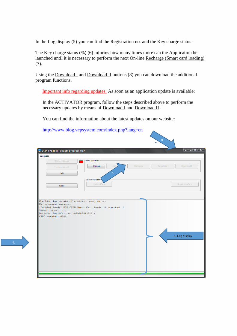
In the Log display (5) you can find the Registration no. and the Key charge status.
The Key charge status (%) (6) informs how many times more can the Application be
launched until it is necessary to perform the next On-line Recharge (Smart card loading)
(7).
Using the Download I and Download II buttons (8) you can download the additional
program functions.
Important info regarding updates: As soon as an application update is available:
In the ACTIVATOR program, follow the steps described above to perform the
necessary updates by means of Download I and Download II.
You can find the information about the latest updates on our website:
http://www.blog.vcpsystem.com/index.php?lang=en
8.
6.
7.
5. Log display
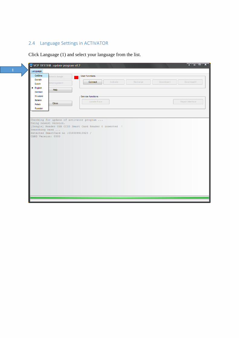
2.4 Language Settings in ACTIVATOR
Click Language (1) and select your language from the list.
1
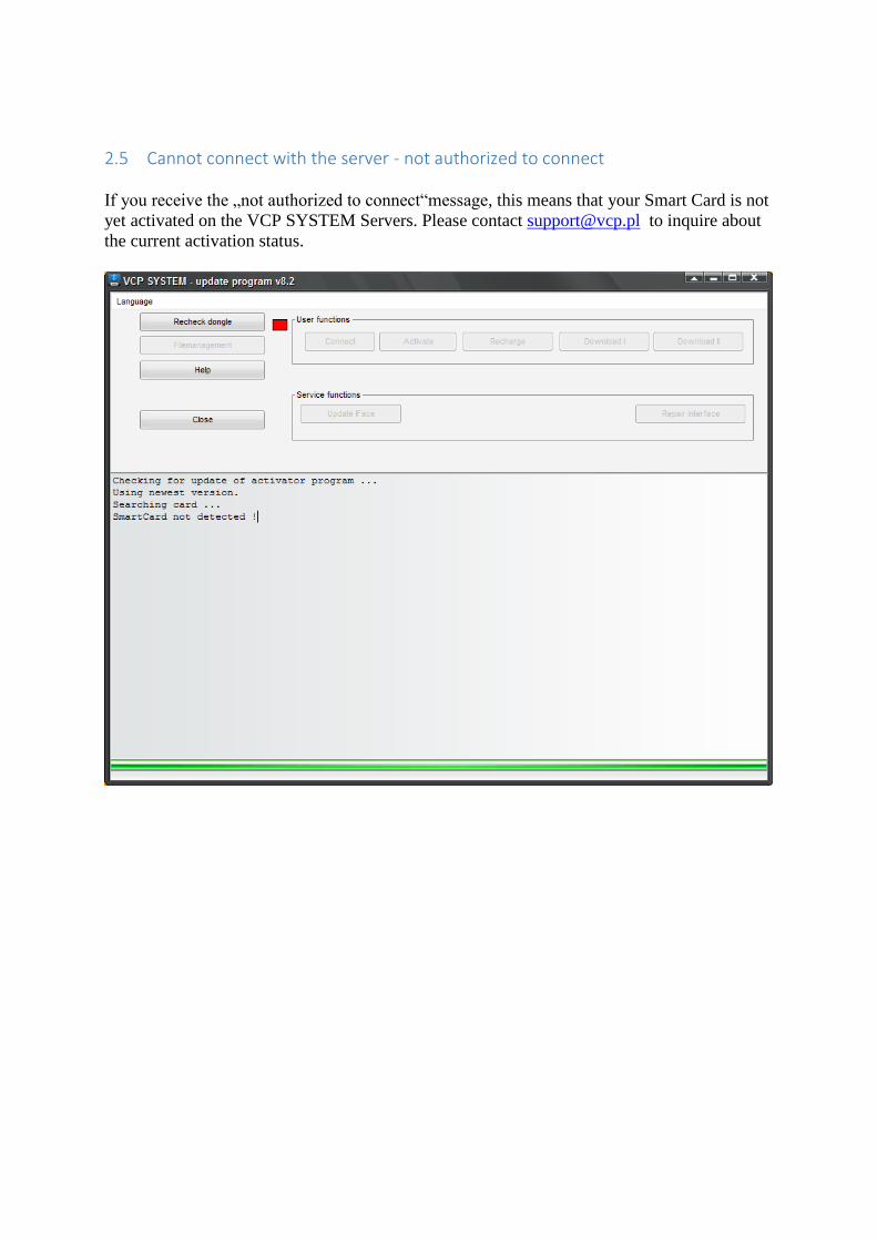
2.5 Cannot connect with the server - not authorized to connect
If you receive the „not authorized to connect“message, this means that your Smart Card is not
yet activated on the VCP SYSTEM Servers. Please contact [email protected] to inquire about
the current activation status.
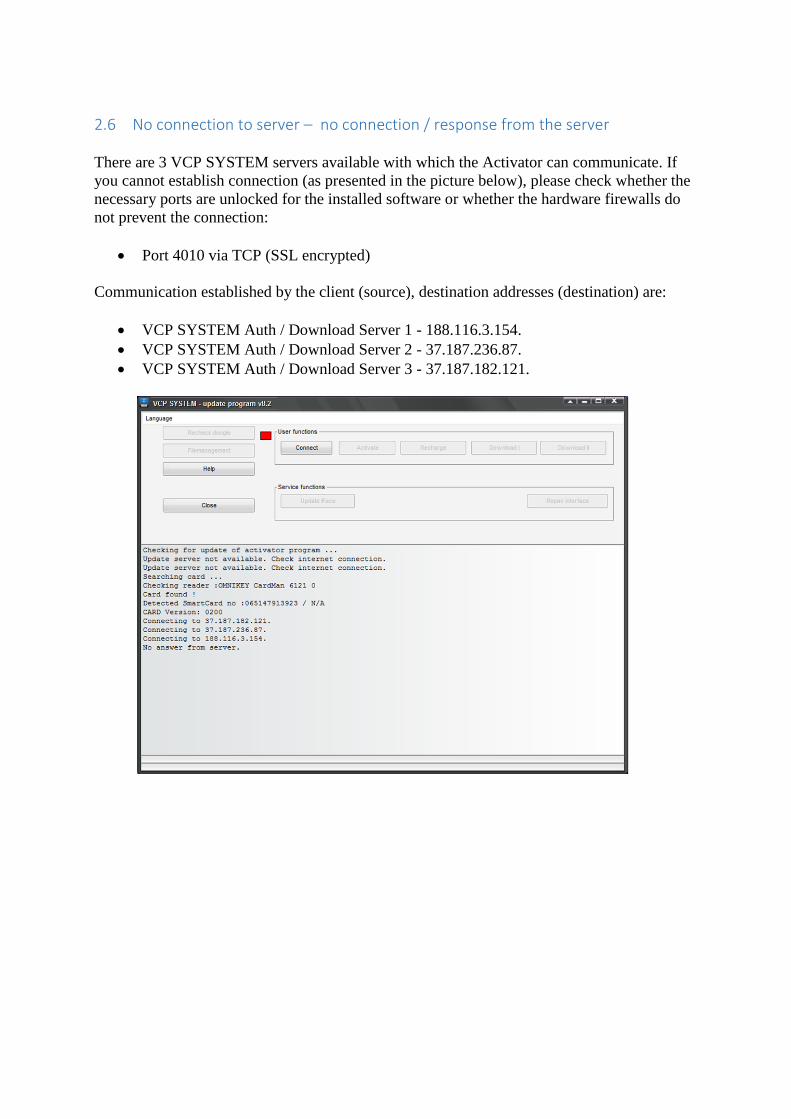
2.6 No connection to server – no connection / response from the server
There are 3 VCP SYSTEM servers available with which the Activator can communicate. If
you cannot establish connection (as presented in the picture below), please check whether the
necessary ports are unlocked for the installed software or whether the hardware firewalls do
not prevent the connection:
Port 4010 via TCP (SSL encrypted)
Communication established by the client (source), destination addresses (destination) are:
VCP SYSTEM Auth / Download Server 1 - 188.116.3.154.
VCP SYSTEM Auth / Download Server 2 - 37.187.236.87.
VCP SYSTEM Auth / Download Server 3 - 37.187.182.121.
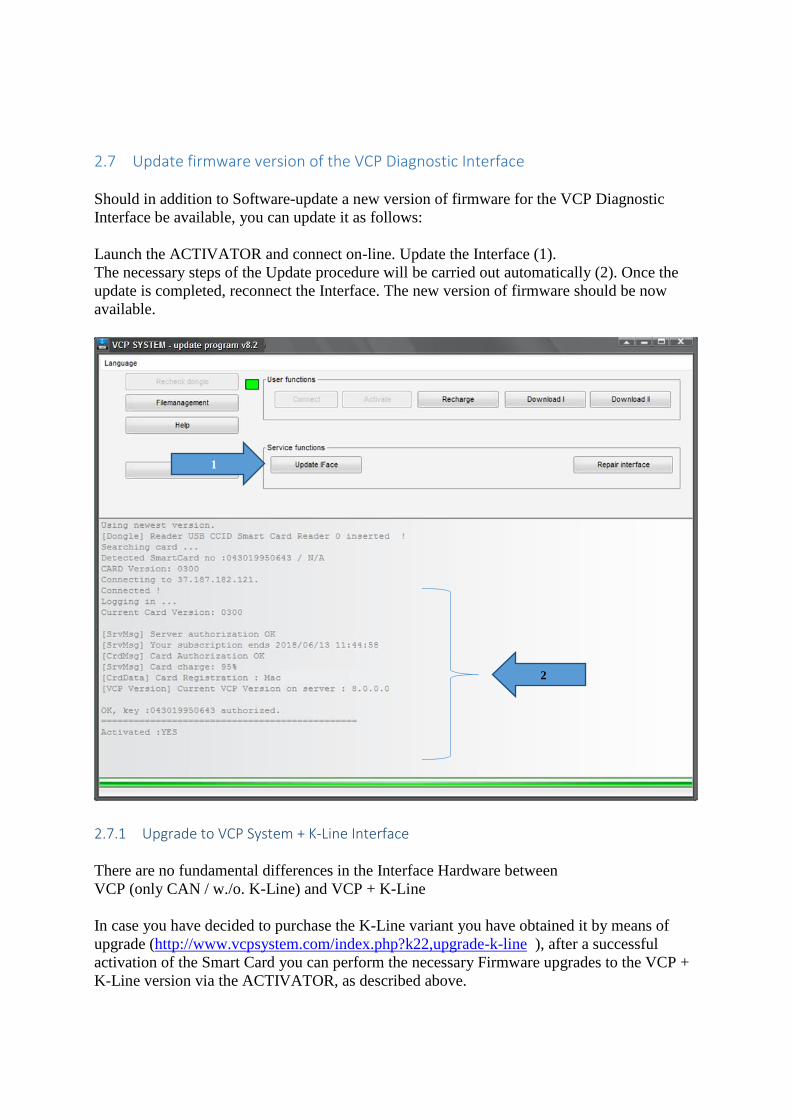
2.7 Update firmware version of the VCP Diagnostic Interface
Should in addition to Software-update a new version of firmware for the VCP Diagnostic
Interface be available, you can update it as follows:
Launch the ACTIVATOR and connect on-line. Update the Interface (1).
The necessary steps of the Update procedure will be carried out automatically (2). Once the
update is completed, reconnect the Interface. The new version of firmware should be now
available.
2.7.1 Upgrade to VCP System + K-Line Interface
There are no fundamental differences in the Interface Hardware between
VCP (only CAN / w./o. K-Line) and VCP + K-Line
In case you have decided to purchase the K-Line variant you have obtained it by means of
upgrade (http://www.vcpsystem.com/index.php?k22,upgrade-k-line ), after a successful
activation of the Smart Card you can perform the necessary Firmware upgrades to the VCP +
K-Line version via the ACTIVATOR, as described above.
1
2
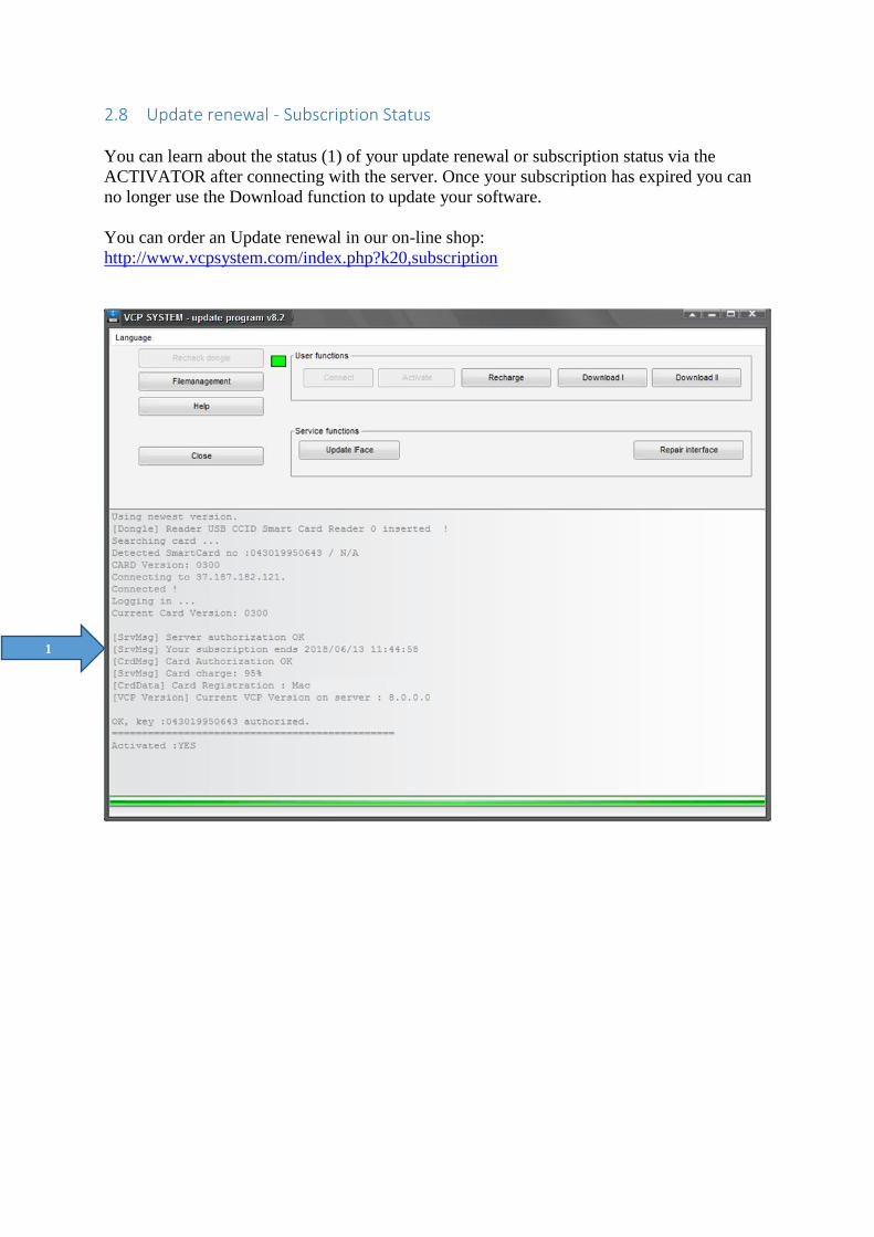
2.8 Update renewal - Subscription Status
You can learn about the status (1) of your update renewal or subscription status via the
ACTIVATOR after connecting with the server. Once your subscription has expired you can
no longer use the Download function to update your software.
You can order an Update renewal in our on-line shop:
http://www.vcpsystem.com/index.php?k20,subscription
1
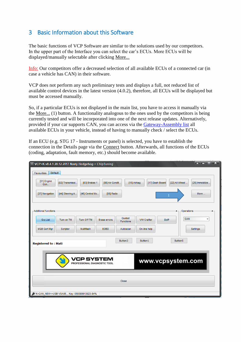
3 Basic Information about this Software
The basic functions of VCP Software are similar to the solutions used by our competitors.
In the upper part of the Interface you can select the car’s ECUs. More ECUs will be
displayed/manually selectable after clicking More...
Info: Our competitors offer a decreased selection of all available ECUs of a connected car (in
case a vehicle has CAN) in their software.
VCP does not perform any such preliminary tests and displays a full, not reduced list of
available control devices in the latest version (4.0.2), therefore, all ECUs will be displayed but
must be accessed manually.
So, if a particular ECUs is not displayed in the main list, you have to access it manually via
the More... (1) button. A functionality analogous to the ones used by the competitors is being
currently tested and will be incorporated into one of the next release updates. Alternatively,
provided if your car supports CAN, you can access via the Gateway-Assembly list all
available ECUs in your vehicle, instead of having to manually check / select the ECUs.
If an ECU (e.g. STG 17 - Instruments or panel) is selected, you have to establish the
connection in the Details page via the Connect button. Afterwards, all functions of the ECUs
(coding, adaptation, fault memory, etc.) should become available.
1
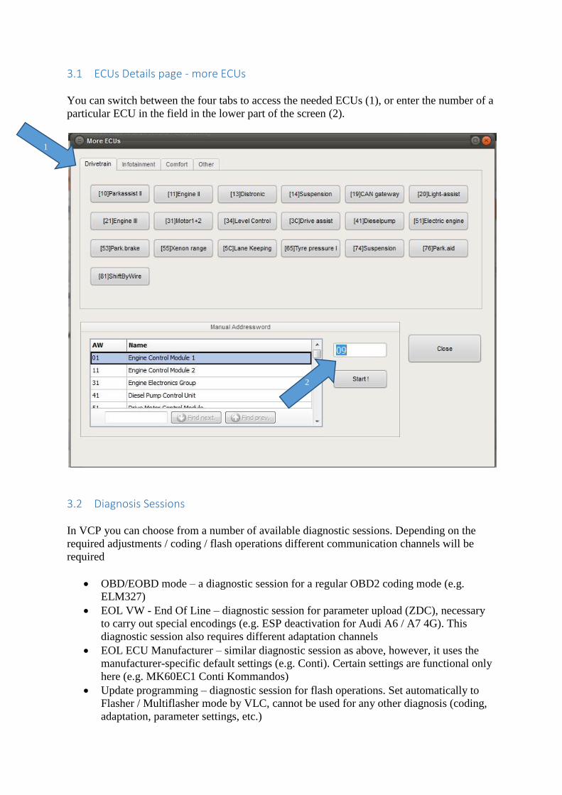
3.1 ECUs Details page - more ECUs
You can switch between the four tabs to access the needed ECUs (1), or enter the number of a
particular ECU in the field in the lower part of the screen (2).
3.2 Diagnosis Sessions
In VCP you can choose from a number of available diagnostic sessions. Depending on the
required adjustments / coding / flash operations different communication channels will be
required
OBD/EOBD mode – a diagnostic session for a regular OBD2 coding mode (e.g.
ELM327)
EOL VW - End Of Line – diagnostic session for parameter upload (ZDC), necessary
to carry out special encodings (e.g. ESP deactivation for Audi A6 / A7 4G). This
diagnostic session also requires different adaptation channels
EOL ECU Manufacturer – similar diagnostic session as above, however, it uses the
manufacturer-specific default settings (e.g. Conti). Certain settings are functional only
here (e.g. MK60EC1 Conti Kommandos)
Update programming – diagnostic session for flash operations. Set automatically to
Flasher / Multiflasher mode by VLC, cannot be used for any other diagnosis (coding,
adaptation, parameter settings, etc.)
1
2
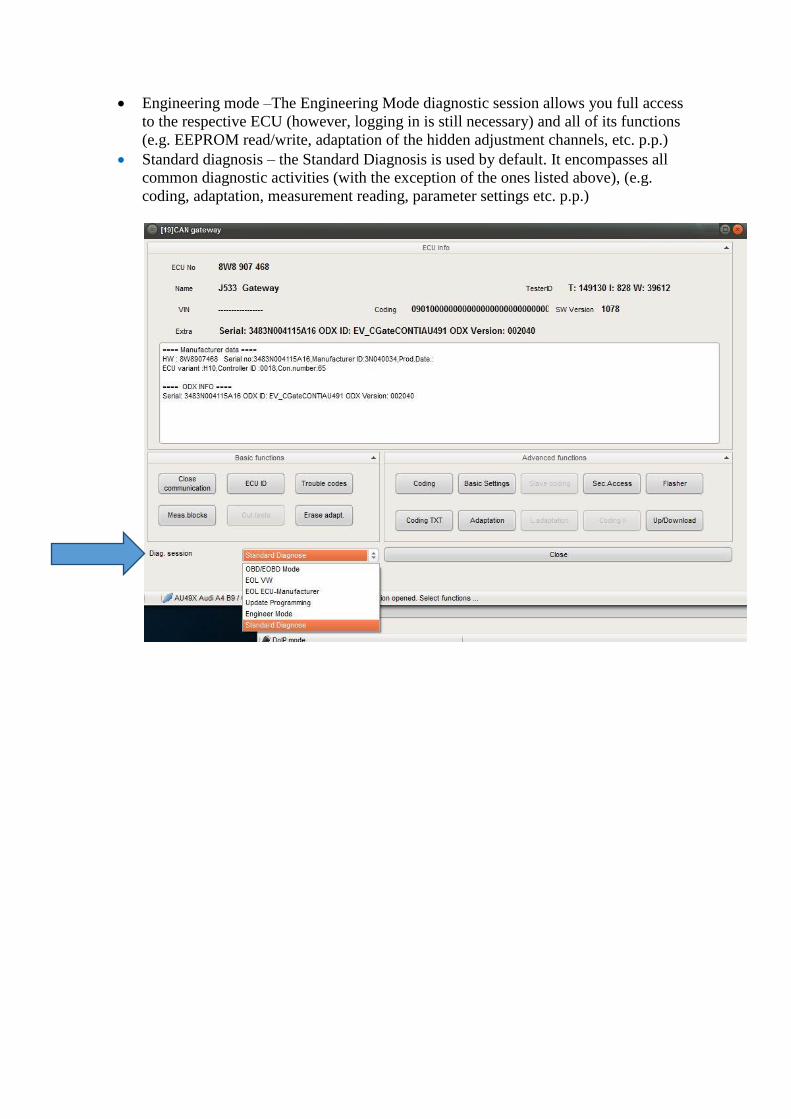
Engineering mode –The Engineering Mode diagnostic session allows you full access
to the respective ECU (however, logging in is still necessary) and all of its functions
(e.g. EEPROM read/write, adaptation of the hidden adjustment channels, etc. p.p.)
Standard diagnosis – the Standard Diagnosis is used by default. It encompasses all
common diagnostic activities (with the exception of the ones listed above), (e.g.
coding, adaptation, measurement reading, parameter settings etc. p.p.)
4 VCP Initial Configuration
After a successful Download of Program Components via the VCP ACTIVATOR you can
launch VCP SYSTEM.
After closing the ACTIVATOR simply double-click the VCP SYSTEM icon on the desktop.
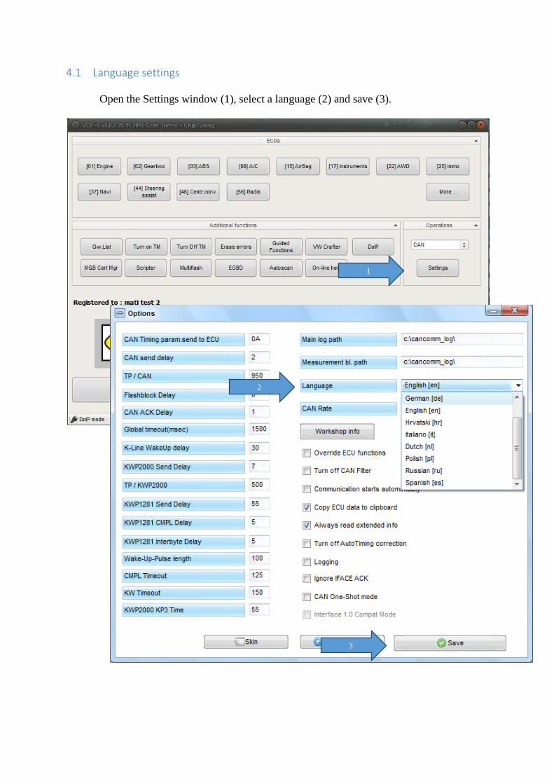
4.1 Language settings
Open the Settings window (1), select a language (2) and save (3).
1
3
2
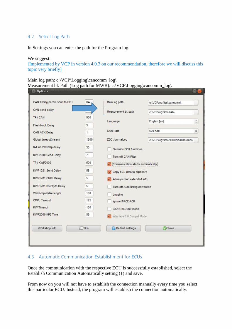
4.2 Select Log Path
In Settings you can enter the path for the Program log.
We suggest:
[Implemented by VCP in version 4.0.3 on our recommendation, therefore we will discuss this
topic very briefly]
Main log path: c:\VCP\Logging\cancomm_log\
Measurement bl. Path (Log path for MWB): c:\VCP\Logging\cancomm_log\
4.3 Automatic Communication Establishment for ECUs
Once the communication with the respective ECU is successfully established, select the
Establish Communication Automatically setting (1) and save.
From now on you will not have to establish the connection manually every time you select
this particular ECU. Instead, the program will establish the connection automatically.
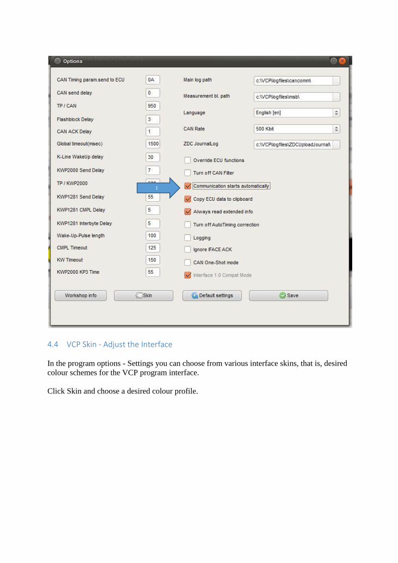
4.4 VCP Skin - Adjust the Interface
In the program options - Settings you can choose from various interface skins, that is, desired
colour schemes for the VCP program interface.
Click Skin and choose a desired colour profile.
1
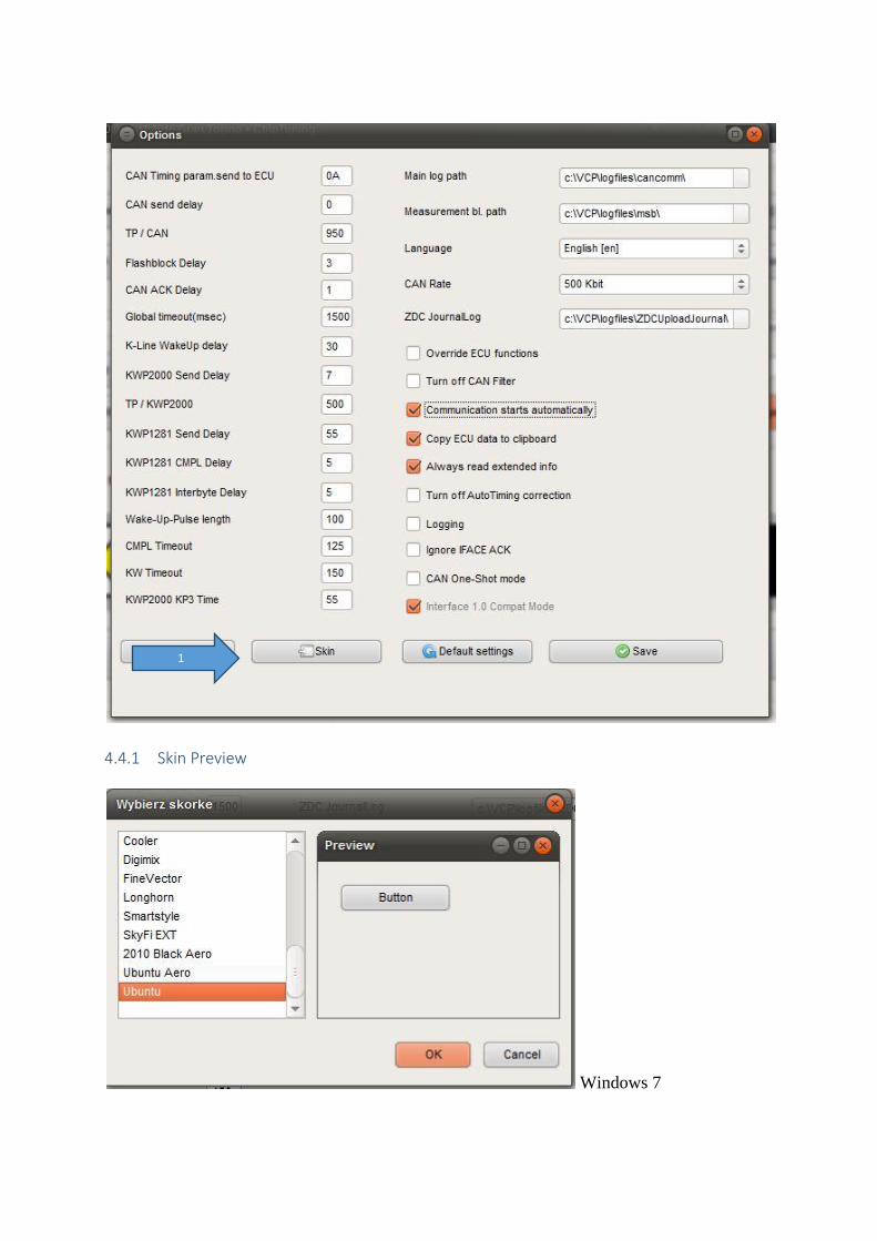
4.4.1 Skin Preview
Windows 7
1
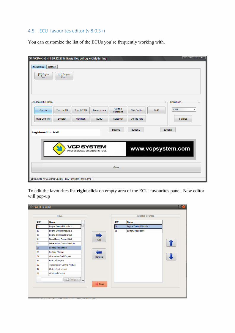
4.5 ECU favourites editor (v 8.0.3+)
You can customize the list of the ECUs you’re frequently working with.
To edit the favourites list right-click on empty area of the ECU-favourites panel. New editor
will pop-up
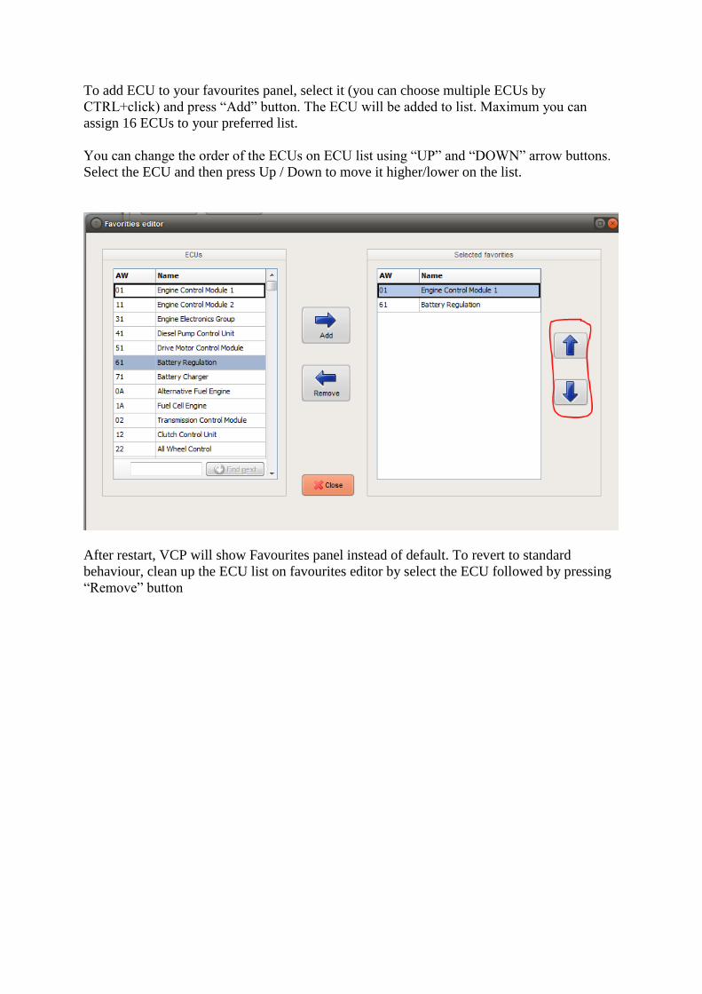
To add ECU to your favourites panel, select it (you can choose multiple ECUs by
CTRL+click) and press “Add” button. The ECU will be added to list. Maximum you can
assign 16 ECUs to your preferred list.
You can change the order of the ECUs on ECU list using “UP” and “DOWN” arrow buttons.
Select the ECU and then press Up / Down to move it higher/lower on the list.
After restart, VCP will show Favourites panel instead of default. To revert to standard
behaviour, clean up the ECU list on favourites editor by select the ECU followed by pressing
“Remove” button
5 OCF – One Click Functions
The VCP SYSTEM software is provided with the
OCF functionality (One-click functions) which gives you the advantage of easy access to
various functions, such as automatic coding / performing adjustment settings of ECU
functions or upload ZDC parameter files using the data uploader.
5.1 OCF - ZDC-Container - Data Upload Assistant for Parameter Settings
By using the ZDC Container Upload you can upload the necessary parameter settings files
(e.g. to enable VIM in all MQB models) into the respective ECUs. You can read below where
to obtain these files (5.1.1) and how to upload them. (5.1.2)
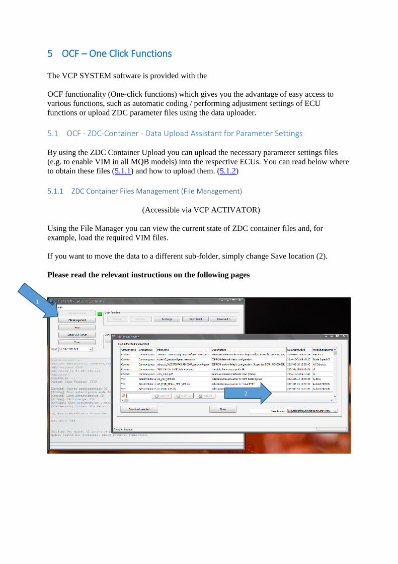
5.1.1 ZDC Container Files Management (File Management)
(Accessible via VCP ACTIVATOR)
Using the File Manager you can view the current state of ZDC container files and, for
example, load the required VIM files.
If you want to move the data to a different sub-folder, simply change Save location (2).
Please read the relevant instructions on the following pages
2
1
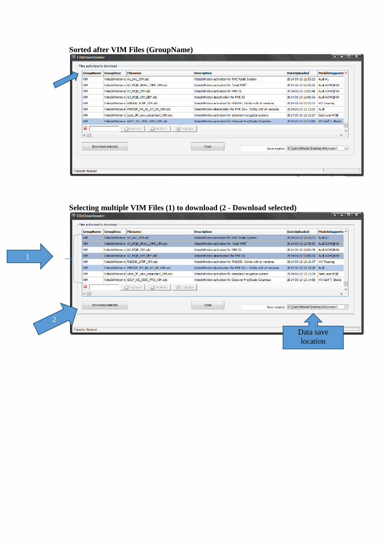
Sorted after VIM Files (GroupName)
Selecting multiple VIM Files (1) to download (2 - Download selected)
2
1
Data save
location
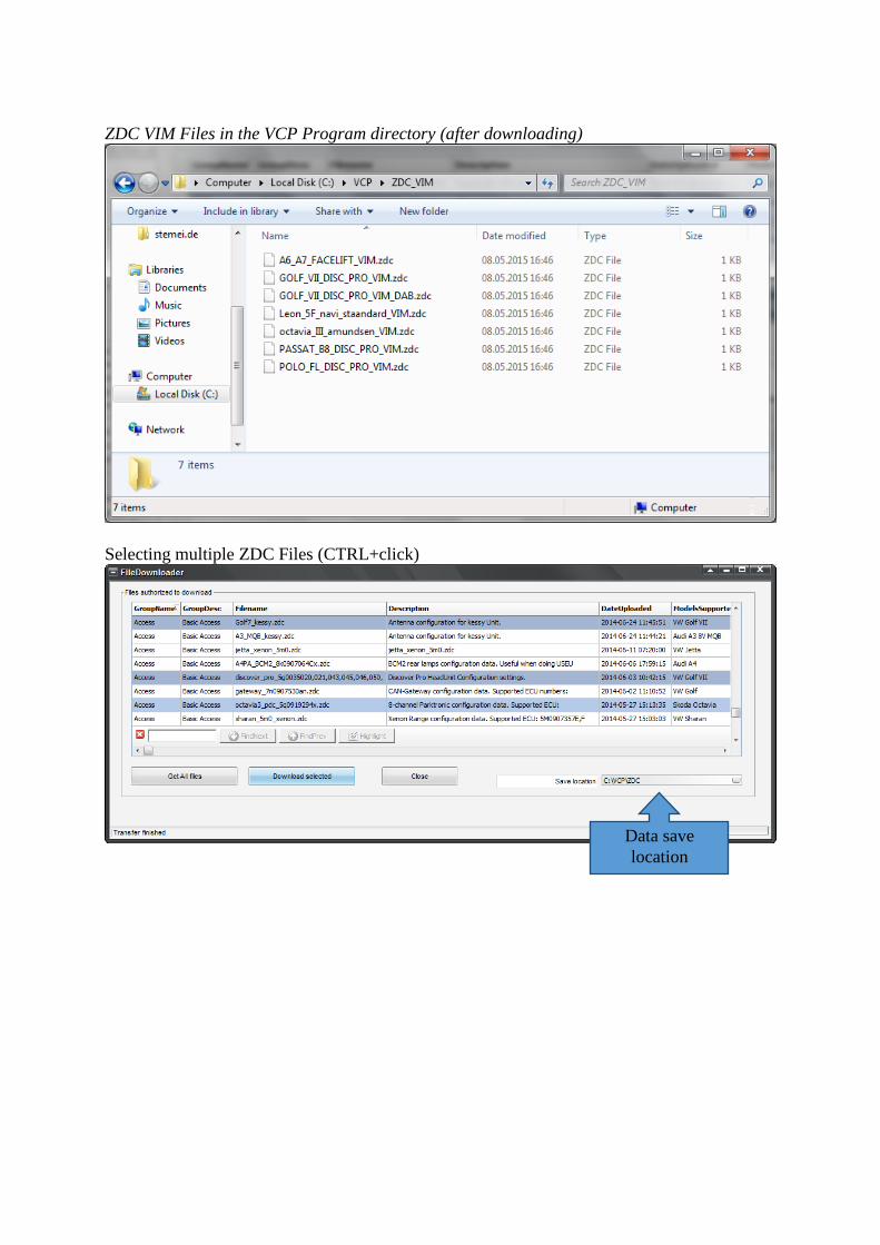
ZDC VIM Files in the VCP Program directory (after downloading)
Selecting multiple ZDC Files (CTRL+click)
Data save
location
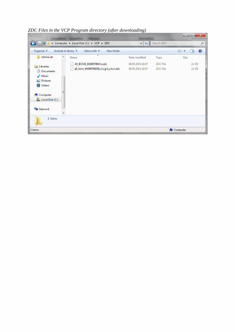
ZDC Files in the VCP Program directory (after downloading)
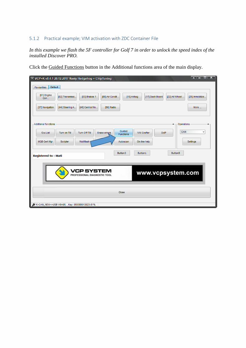
5.1.2 Practical example; VIM activation with ZDC Container File
In this example we flash the 5F controller for Golf 7 in order to unlock the speed index of the
installed Discover PRO.
Click the Guided Functions button in the Additional functions area of the main display.
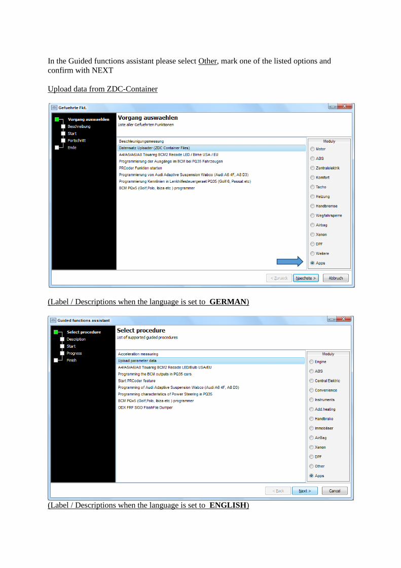
In the Guided functions assistant please select Other, mark one of the listed options and
confirm with NEXT
Upload data from ZDC-Container
(Label / Descriptions when the language is set to GERMAN)
(Label / Descriptions when the language is set to ENGLISH)
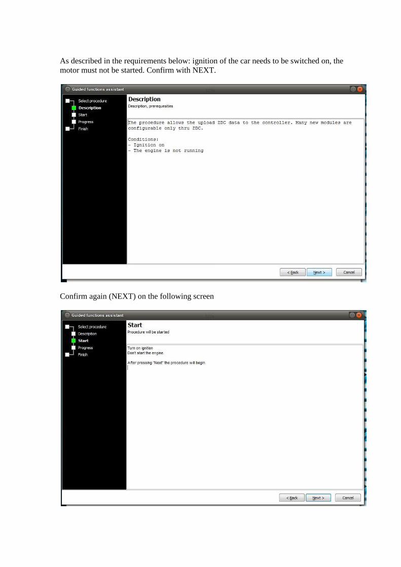
As described in the requirements below: ignition of the car needs to be switched on, the
motor must not be started. Confirm with NEXT.
Confirm again (NEXT) on the following screen
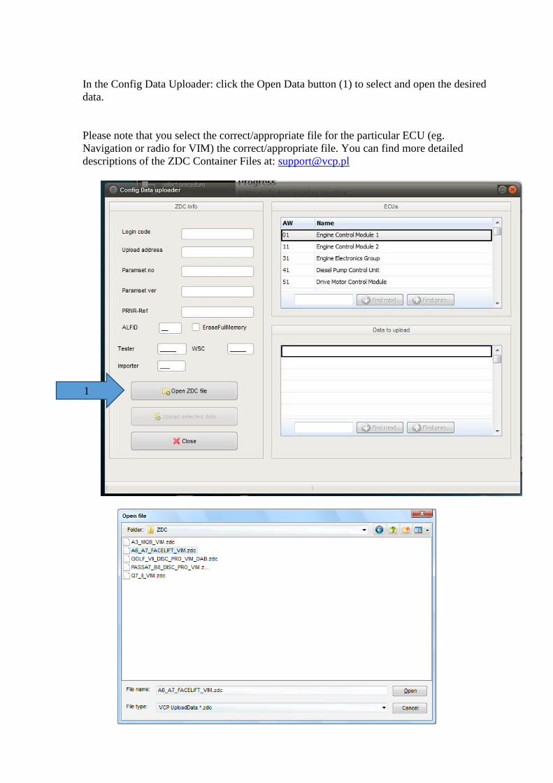
In the Config Data Uploader: click the Open Data button (1) to select and open the desired
data.
Please note that you select the correct/appropriate file for the particular ECU (eg.
Navigation or radio for VIM) the correct/appropriate file. You can find more detailed
descriptions of the ZDC Container Files at: [email protected]
1
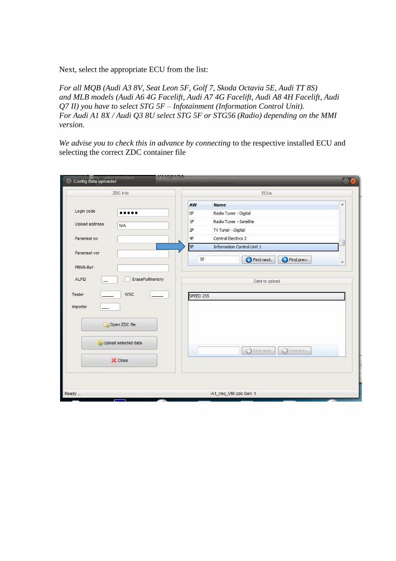
Next, select the appropriate ECU from the list:
For all MQB (Audi A3 8V, Seat Leon 5F, Golf 7, Skoda Octavia 5E, Audi TT 8S)
and MLB models (Audi A6 4G Facelift, Audi A7 4G Facelift, Audi A8 4H Facelift, Audi
Q7 II) you have to select STG 5F – Infotainment (Information Control Unit).
For Audi A1 8X / Audi Q3 8U select STG 5F or STG56 (Radio) depending on the MMI
version.
We advise you to check this in advance by connecting to the respective installed ECU and
selecting the correct ZDC container file
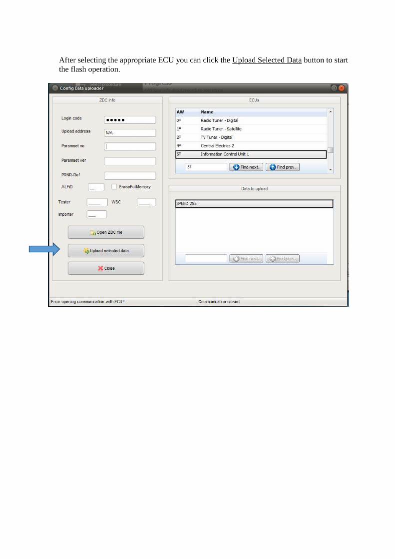
After selecting the appropriate ECU you can click the Upload Selected Data button to start
the flash operation.
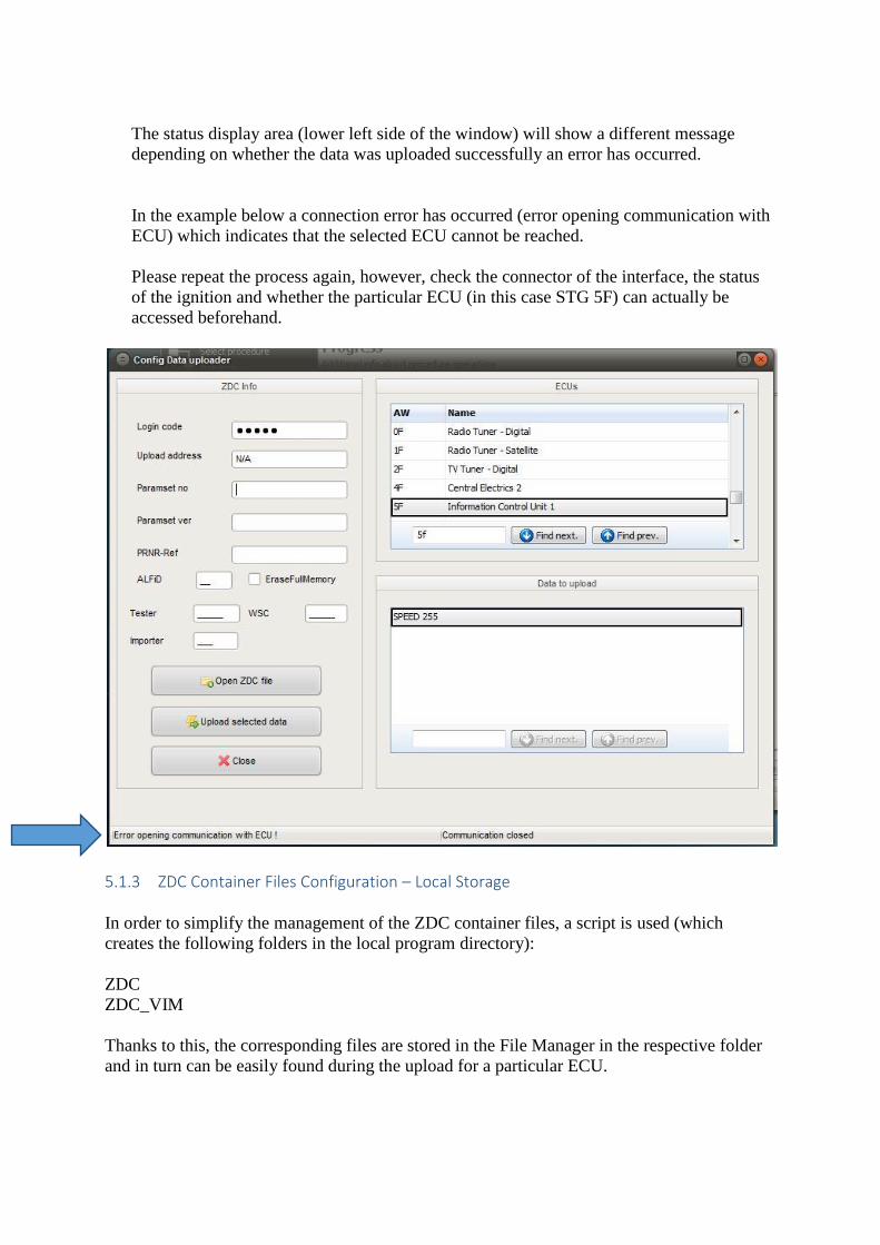
The status display area (lower left side of the window) will show a different message
depending on whether the data was uploaded successfully an error has occurred.
In the example below a connection error has occurred (error opening communication with
ECU) which indicates that the selected ECU cannot be reached.
Please repeat the process again, however, check the connector of the interface, the status
of the ignition and whether the particular ECU (in this case STG 5F) can actually be
accessed beforehand.
5.1.3 ZDC Container Files Configuration – Local Storage
In order to simplify the management of the ZDC container files, a script is used (which
creates the following folders in the local program directory):
ZDC
ZDC_VIM
Thanks to this, the corresponding files are stored in the File Manager in the respective folder
and in turn can be easily found during the upload for a particular ECU.

VCP_Ordnerstruktur_ZDC.bat
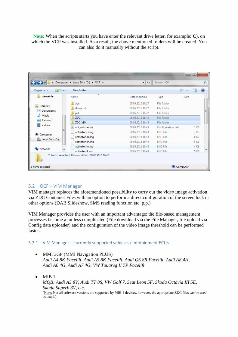
Note: When the scripts starts you have enter the relevant drive letter, for example: C), on
which the VCP was installed. As a result, the above mentioned folders will be created. You
can also do it manually without the script.
5.2 OCF – VIM Manager VIM manager replaces the aforementioned possibility to carry out the video image activation
via ZDC Container Files with an option to perform a direct configuration of the screen lock or
other options (DAB Slideshow, SMS reading function etc. p.p.).
VIM Manager provides the user with an important advantage: the file-based management
processes become a lot less complicated (File download via the File Manager, file upload via
Config data uploader) and the configuration of the video image threshold can be performed
faster.
5.2.1 VIM Manager – currently supported vehicles / Infotainment ECUs
MMI 3GP (MMI Navigation PLUS)
Audi A4 8K Facelift, Audi A5 8K Facelift, Audi Q5 8R Facelift, Audi A8 4H,
Audi A6 4G, Audi A7 4G, VW Touareg II 7P Facelift
MIB 1
MQB: Audi A3 8V, Audi TT 8S, VW Golf 7, Seat Leon 5F, Skoda Octavia III 5E,
Skoda Superb 3V, etc. (Note: Not all software versions are supported by MIB 1 devices, however, the appropriate ZDC files can be used
as usual.)
MIB 2
MQB: Audi A3 8V, Audi TT 8S, VW Golf 7, Seat Leon 5F, Skoda Octavia III 5E,
Skoda Superb 3V, etc
MLB: Audi A6 4G Facelift, Audi A7 4G Facelift, Audi A8 4H Facelift
MLB Evo Platform: Audi A4 8W, Audi Q7 4M, Audi A5 8S, etc.
RMC
Audi A1 8X, Audi Q3 8U, Audi A6 4G
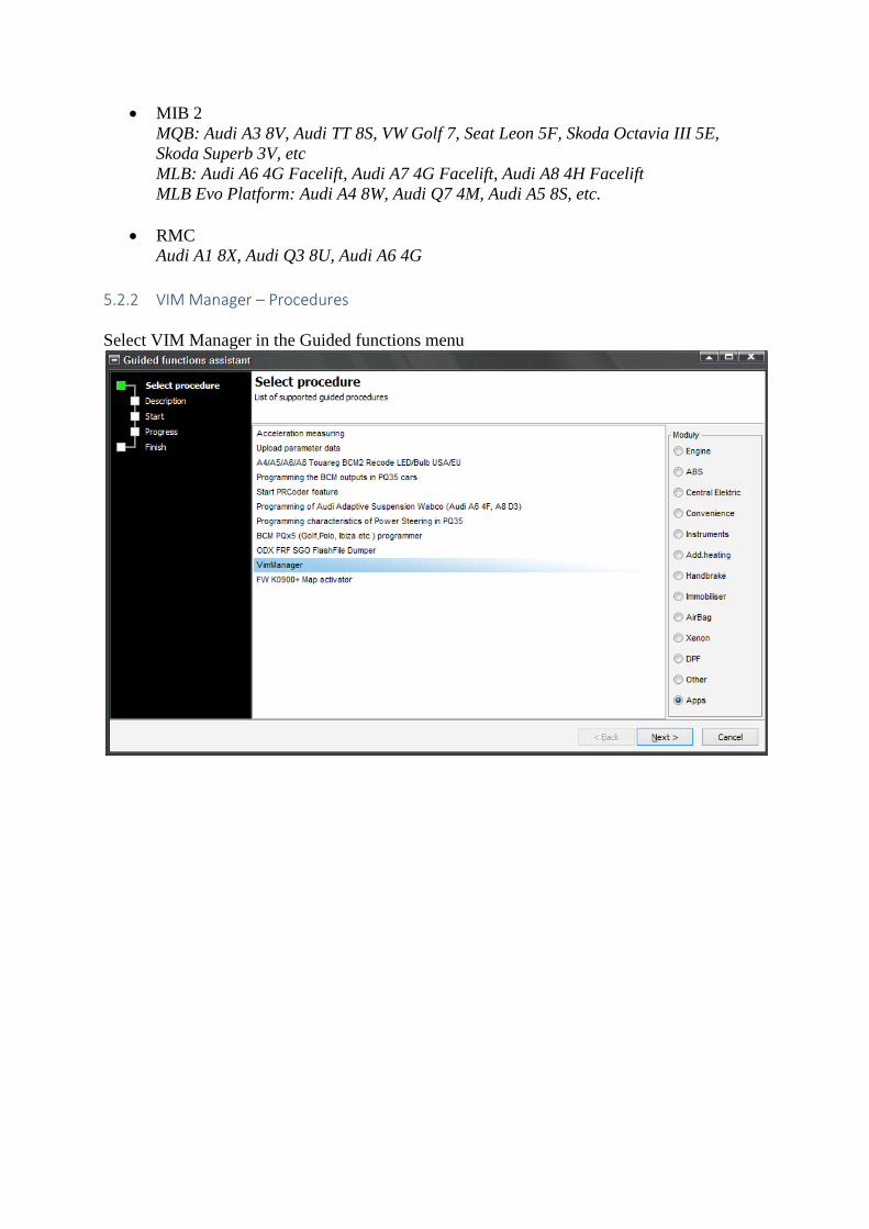
5.2.2 VIM Manager – Procedures
Select VIM Manager in the Guided functions menu
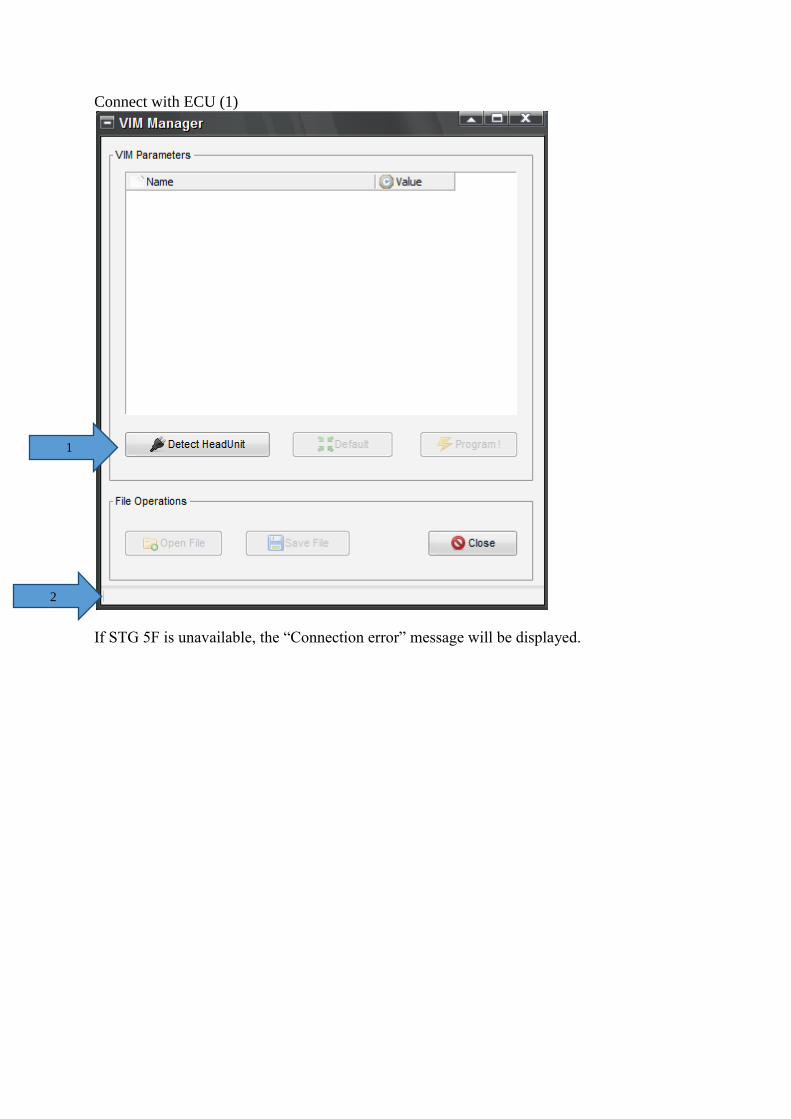
Connect with ECU (1)
If STG 5F is unavailable, the “Connection error” message will be displayed.
1
2
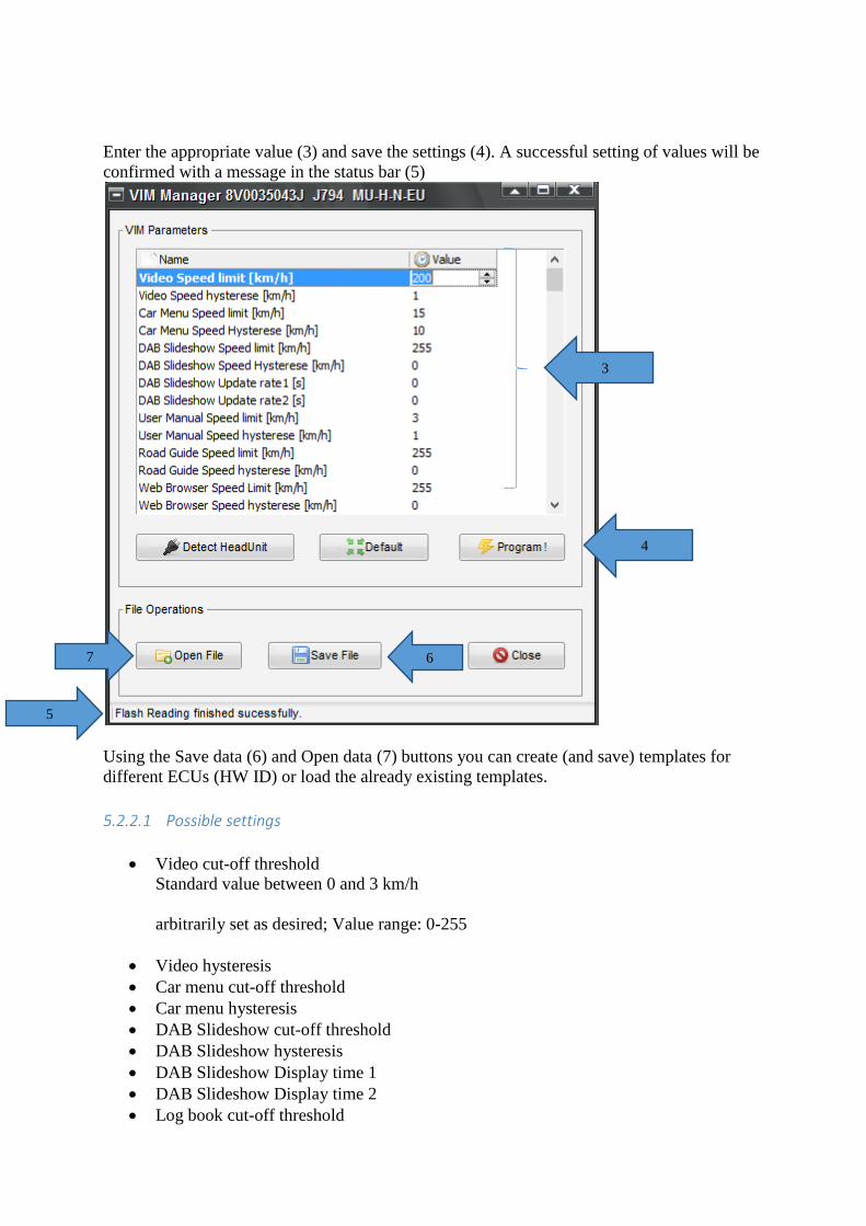
Enter the appropriate value (3) and save the settings (4). A successful setting of values will be
confirmed with a message in the status bar (5)
Using the Save data (6) and Open data (7) buttons you can create (and save) templates for
different ECUs (HW ID) or load the already existing templates.
5.2.2.1 Possible settings
Video cut-off threshold
Standard value between 0 and 3 km/h
arbitrarily set as desired; Value range: 0-255
Video hysteresis
Car menu cut-off threshold
Car menu hysteresis
DAB Slideshow cut-off threshold
DAB Slideshow hysteresis
DAB Slideshow Display time 1
DAB Slideshow Display time 2
Log book cut-off threshold
3
4
6 7
5

Log book hysteresis
Travel guide cut-off threshold
Travel guide hysteresis
Broadcast-Website (Browser) cut-off threshold
Broadcast-Website (Browser) hysteresis
Destination input cut-off threshold
Destination input hysteresis
BT-bonding cut-off threshold
BT-bonding hysteresis
Messaging Text Editor cut-off threshold
Messaging Text Editor hysteresis
Radiotext / Tooltip cut-off threshold
Radiotext / Tooltip hysteresis
Radiotext / Tooltip display time
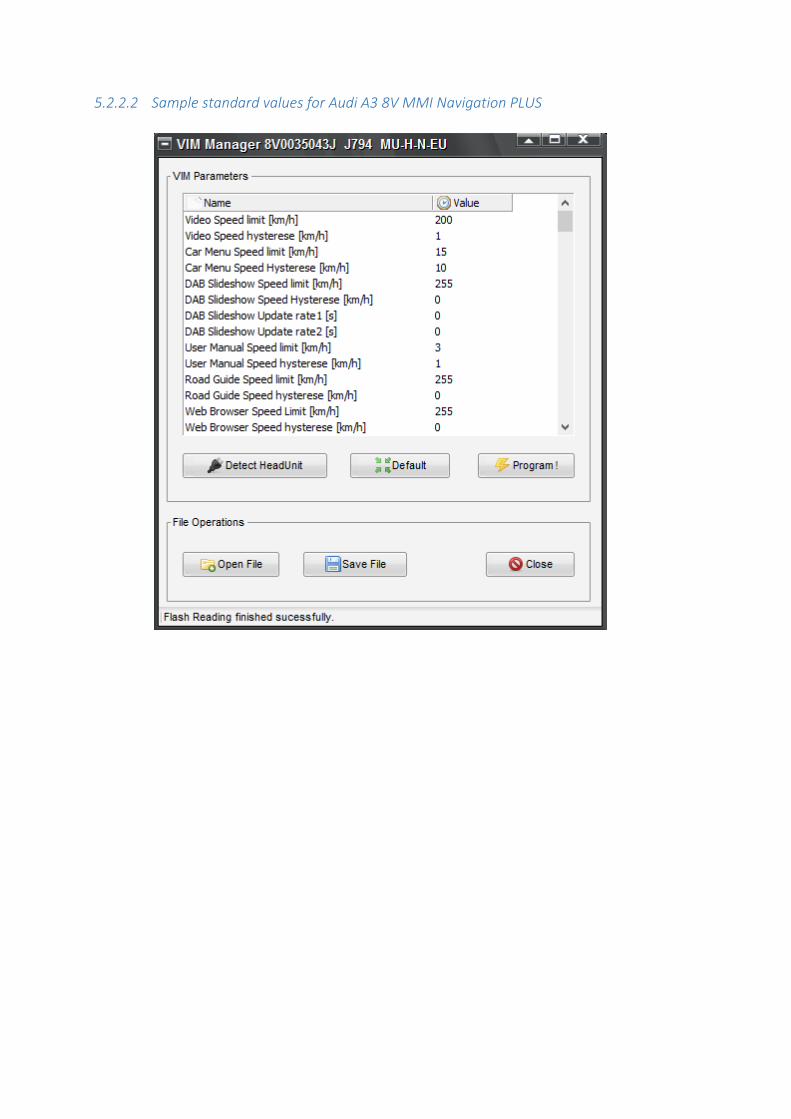
5.2.2.2 Sample standard values for Audi A3 8V MMI Navigation PLUS
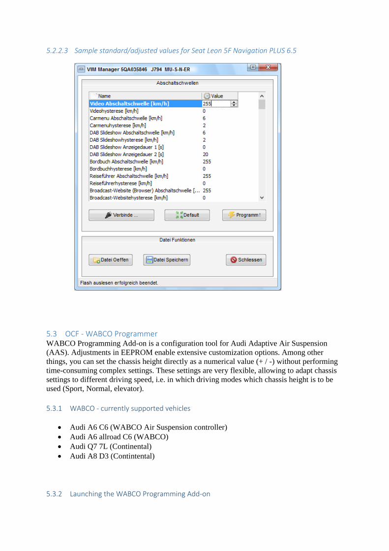
5.2.2.3 Sample standard/adjusted values for Seat Leon 5F Navigation PLUS 6.5
5.3 OCF - WABCO Programmer WABCO Programming Add-on is a configuration tool for Audi Adaptive Air Suspension
(AAS). Adjustments in EEPROM enable extensive customization options. Among other
things, you can set the chassis height directly as a numerical value (+ / -) without performing
time-consuming complex settings. These settings are very flexible, allowing to adapt chassis
settings to different driving speed, i.e. in which driving modes which chassis height is to be
used (Sport, Normal, elevator).
5.3.1 WABCO - currently supported vehicles
Audi A6 C6 (WABCO Air Suspension controller)
Audi A6 allroad C6 (WABCO)
Audi Q7 7L (Continental)
Audi A8 D3 (Contintental)
5.3.2 Launching the WABCO Programming Add-on
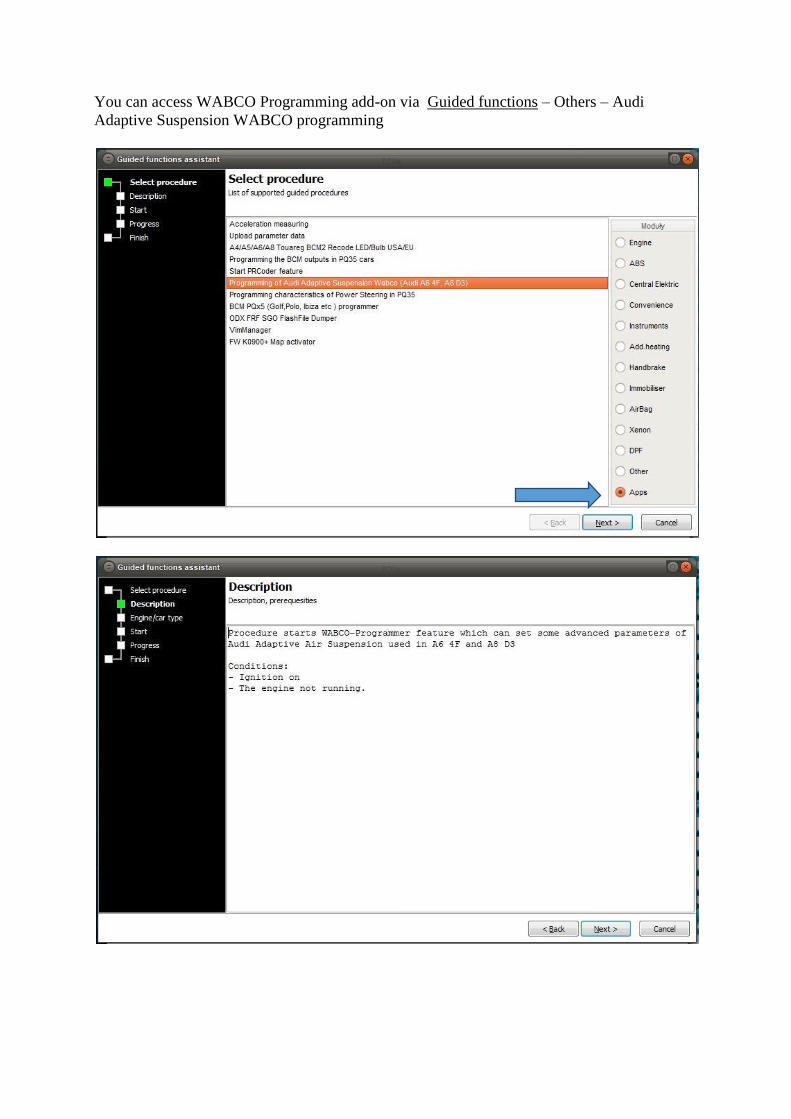
You can access WABCO Programming add-on via Guided functions – Others – Audi
Adaptive Suspension WABCO programming
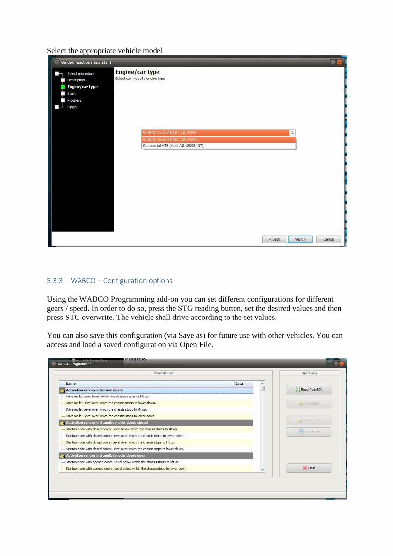
Select the appropriate vehicle model
5.3.3 WABCO – Configuration options
Using the WABCO Programming add-on you can set different configurations for different
gears / speed. In order to do so, press the STG reading button, set the desired values and then
press STG overwrite. The vehicle shall drive according to the set values.
You can also save this configuration (via Save as) for future use with other vehicles. You can
access and load a saved configuration via Open File.
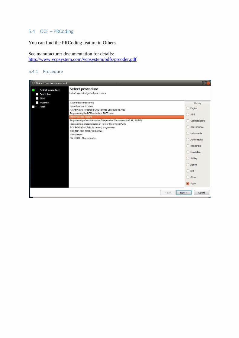
5.4 OCF – PRCoding
You can find the PRCoding feature in Others.
See manufacturer documentation for details:
http://www.vcpsystem.com/vcpsystem/pdfs/prcoder.pdf
5.4.1 Procedure
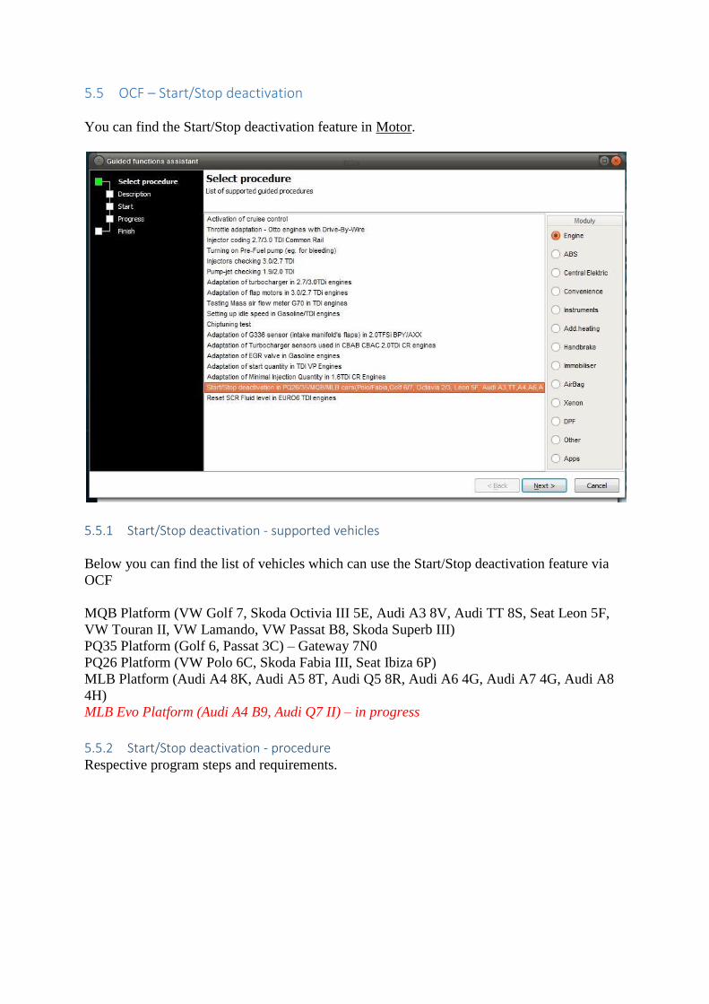
5.5 OCF – Start/Stop deactivation
You can find the Start/Stop deactivation feature in Motor.
5.5.1 Start/Stop deactivation - supported vehicles
Below you can find the list of vehicles which can use the Start/Stop deactivation feature via
OCF
MQB Platform (VW Golf 7, Skoda Octivia III 5E, Audi A3 8V, Audi TT 8S, Seat Leon 5F,
VW Touran II, VW Lamando, VW Passat B8, Skoda Superb III)
PQ35 Platform (Golf 6, Passat 3C) – Gateway 7N0
PQ26 Platform (VW Polo 6C, Skoda Fabia III, Seat Ibiza 6P)
MLB Platform (Audi A4 8K, Audi A5 8T, Audi Q5 8R, Audi A6 4G, Audi A7 4G, Audi A8
4H)
MLB Evo Platform (Audi A4 B9, Audi Q7 II) – in progress
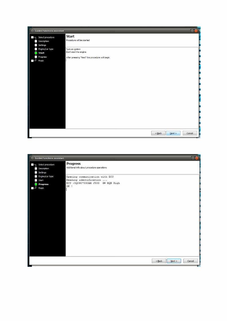
5.5.2 Start/Stop deactivation - procedure Respective program steps and requirements.
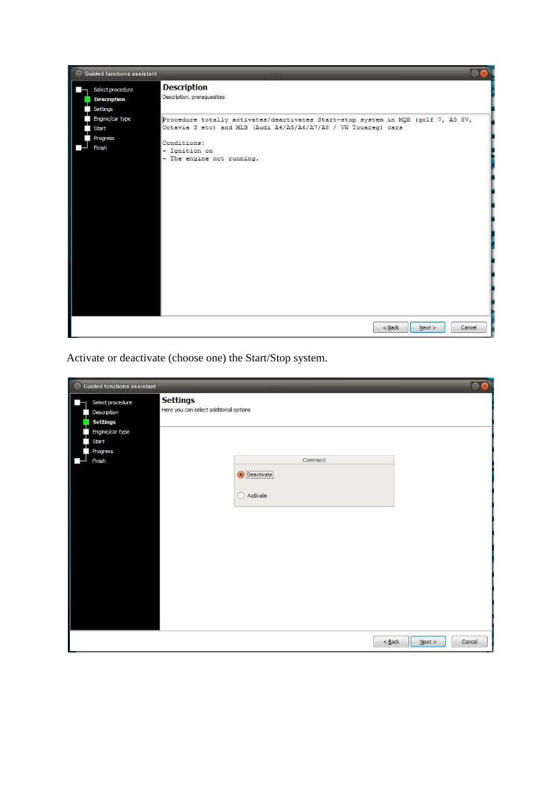
Activate or deactivate (choose one) the Start/Stop system.
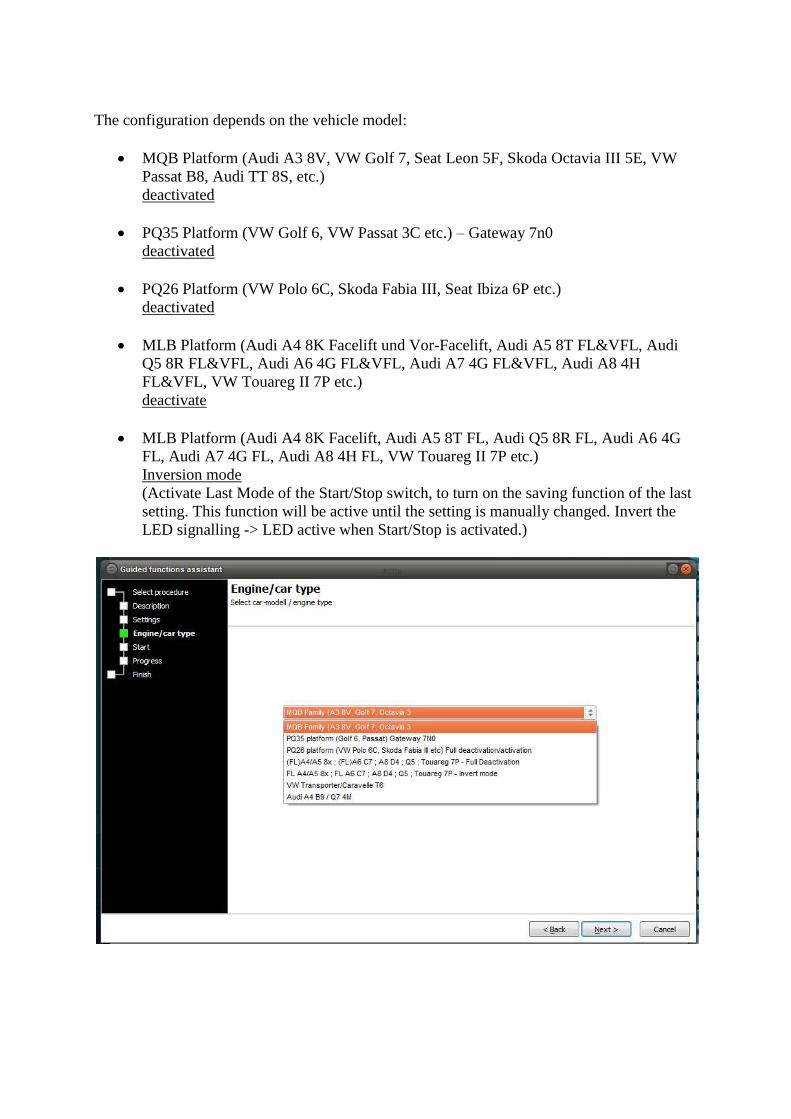
The configuration depends on the vehicle model:
MQB Platform (Audi A3 8V, VW Golf 7, Seat Leon 5F, Skoda Octavia III 5E, VW
Passat B8, Audi TT 8S, etc.)
deactivated
PQ35 Platform (VW Golf 6, VW Passat 3C etc.) – Gateway 7n0
deactivated
PQ26 Platform (VW Polo 6C, Skoda Fabia III, Seat Ibiza 6P etc.)
deactivated
MLB Platform (Audi A4 8K Facelift und Vor-Facelift, Audi A5 8T FL&VFL, Audi
Q5 8R FL&VFL, Audi A6 4G FL&VFL, Audi A7 4G FL&VFL, Audi A8 4H
FL&VFL, VW Touareg II 7P etc.)
deactivate
MLB Platform (Audi A4 8K Facelift, Audi A5 8T FL, Audi Q5 8R FL, Audi A6 4G
FL, Audi A7 4G FL, Audi A8 4H FL, VW Touareg II 7P etc.)
Inversion mode
(Activate Last Mode of the Start/Stop switch, to turn on the saving function of the last
setting. This function will be active until the setting is manually changed. Invert the
LED signalling -> LED active when Start/Stop is activated.)
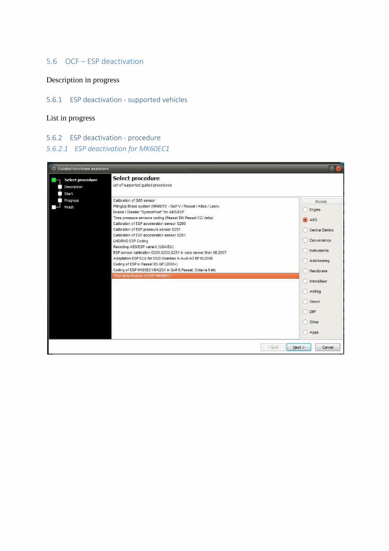
5.6 OCF – ESP deactivation
Description in progress
5.6.1 ESP deactivation - supported vehicles
List in progress
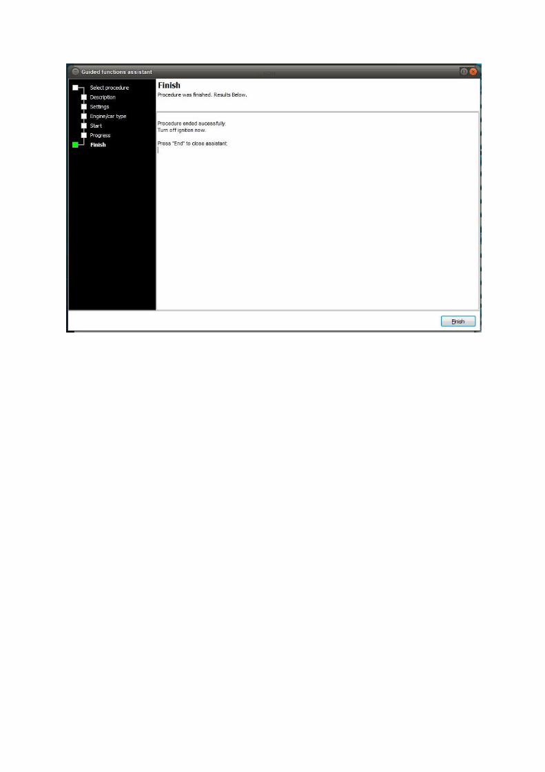
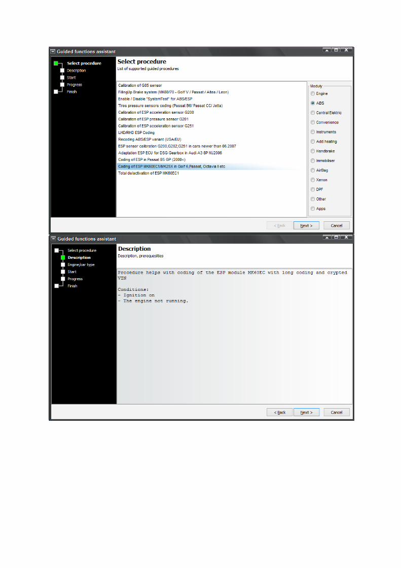
5.6.2 ESP deactivation - procedure
5.6.2.1 ESP deactivation for MK60EC1
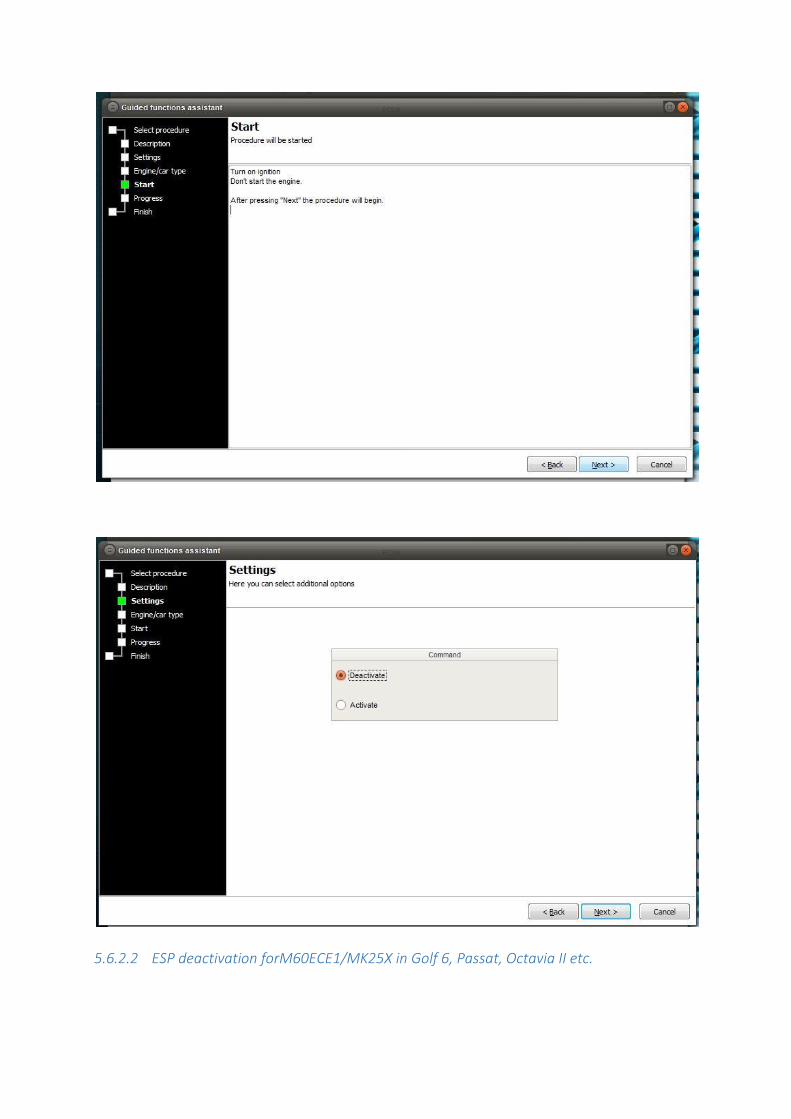
5.6.2.2 ESP deactivation forM60ECE1/MK25X in Golf 6, Passat, Octavia II etc.
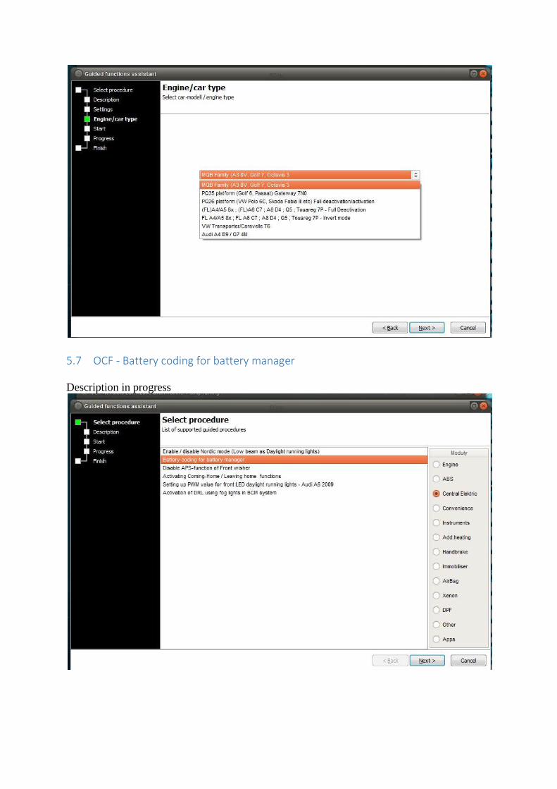
5.7 OCF - Battery coding for battery manager
Description in progress
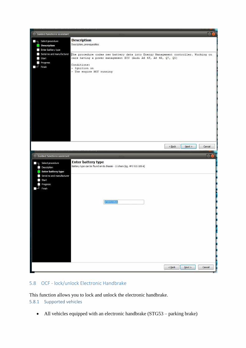
5.8 OCF - lock/unlock Electronic Handbrake
This function allows you to lock and unlock the electronic handbrake.
5.8.1 Supported vehicles
All vehicles equipped with an electronic handbrake (STG53 – parking brake)
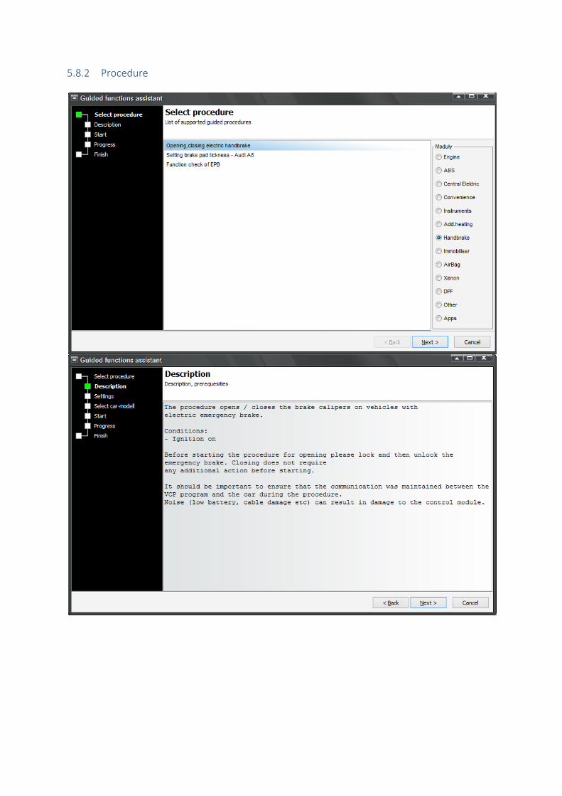
5.8.2 Procedure
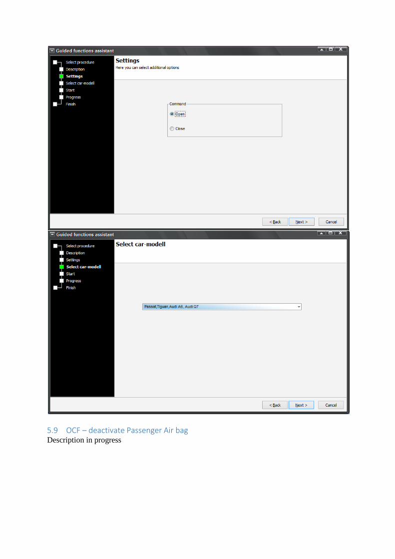
5.9 OCF – deactivate Passenger Air bag Description in progress

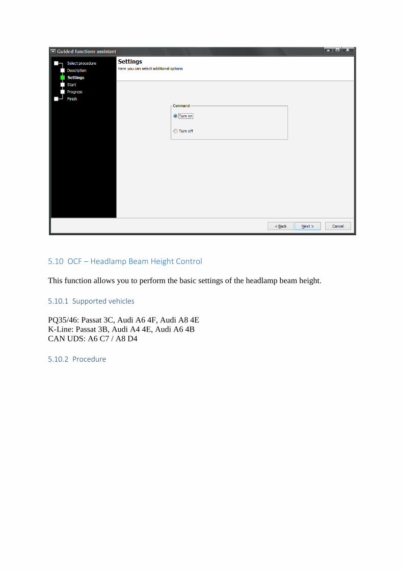
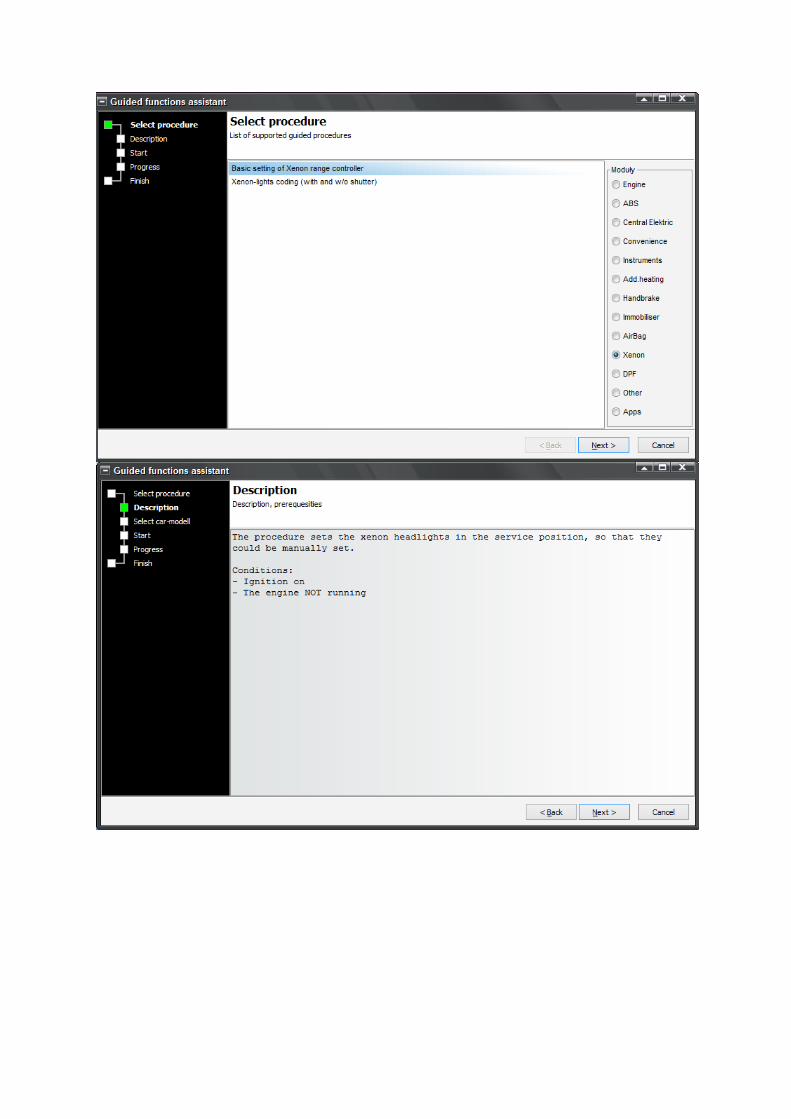
5.10 OCF – Headlamp Beam Height Control
This function allows you to perform the basic settings of the headlamp beam height.
5.10.1 Supported vehicles
PQ35/46: Passat 3C, Audi A6 4F, Audi A8 4E
K-Line: Passat 3B, Audi A4 4E, Audi A6 4B
CAN UDS: A6 C7 / A8 D4
5.10.2 Procedure
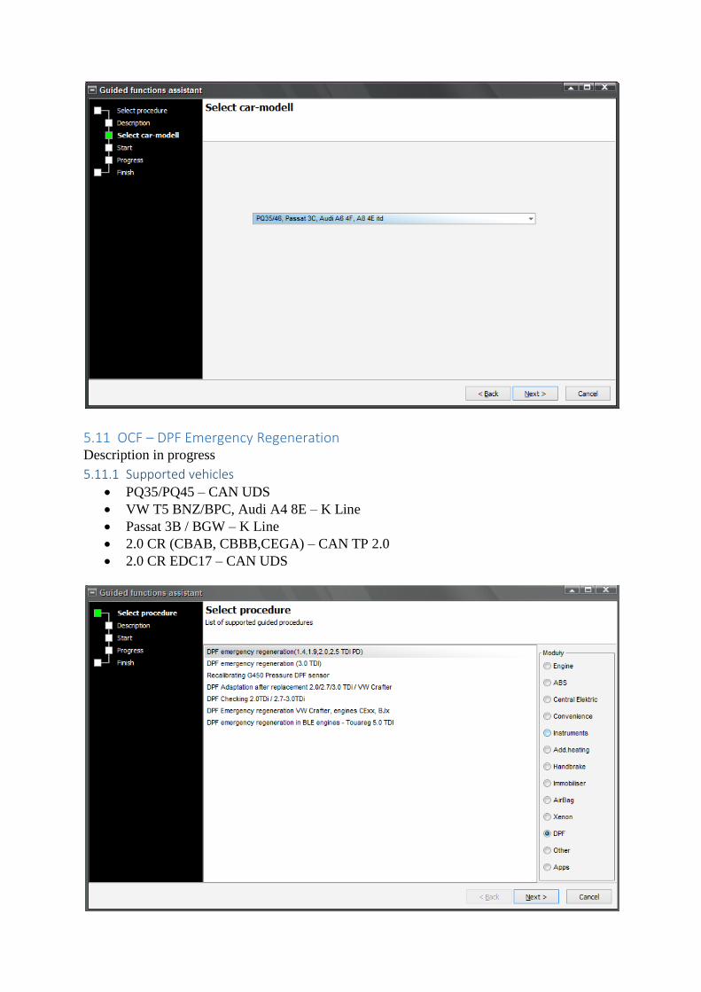
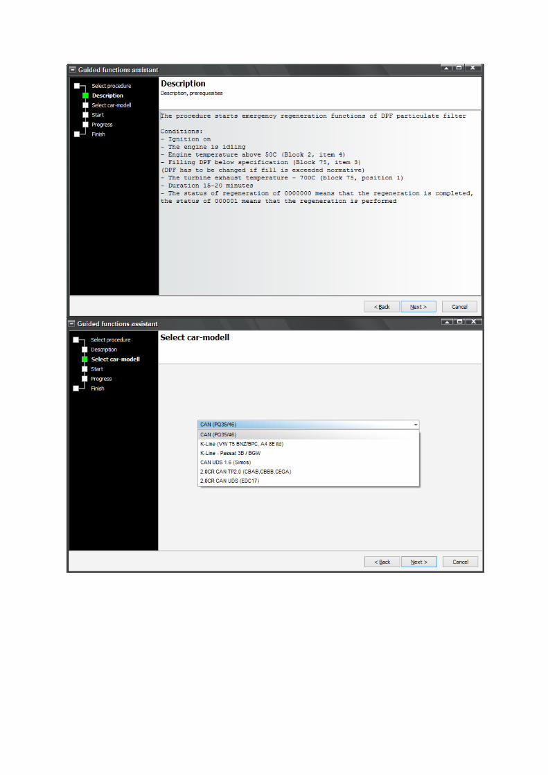
5.11 OCF – DPF Emergency Regeneration Description in progress
5.11.1 Supported vehicles
PQ35/PQ45 – CAN UDS
VW T5 BNZ/BPC, Audi A4 8E – K Line
Passat 3B / BGW – K Line
2.0 CR (CBAB, CBBB,CEGA) – CAN TP 2.0
2.0 CR EDC17 – CAN UDS
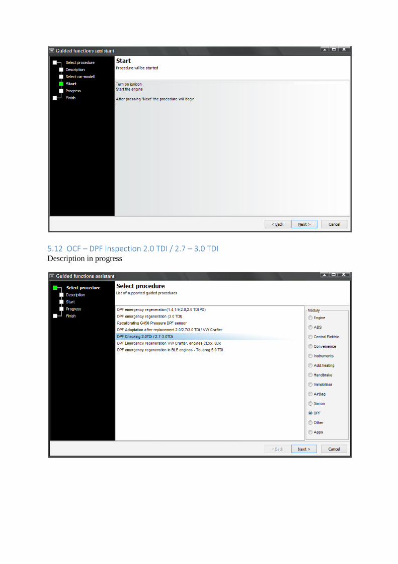
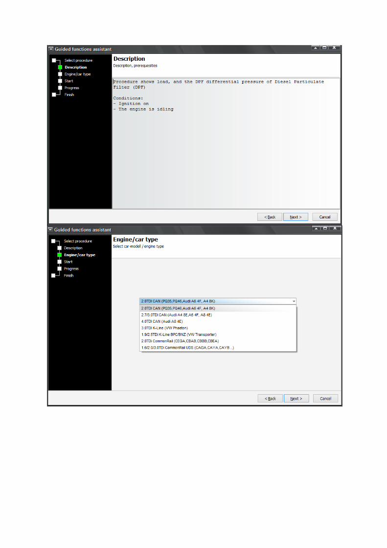
5.12 OCF – DPF Inspection 2.0 TDI / 2.7 – 3.0 TDI Description in progress
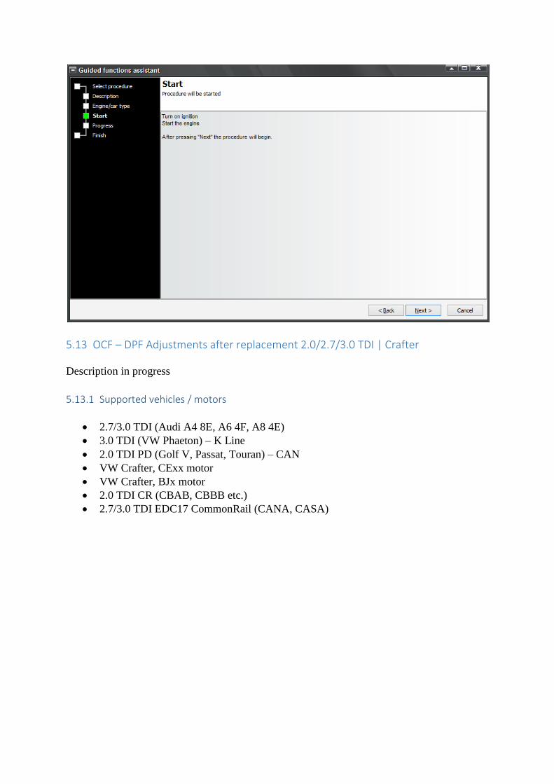
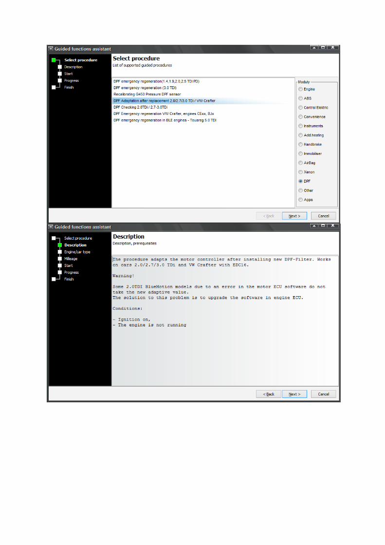
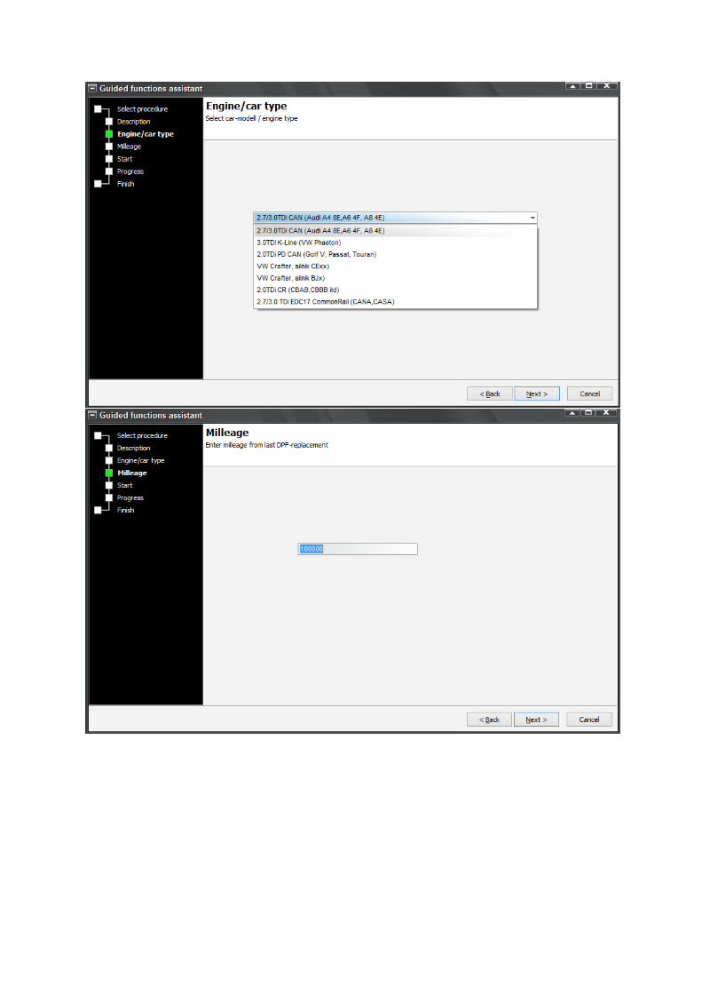
5.13 OCF – DPF Adjustments after replacement 2.0/2.7/3.0 TDI | Crafter
Description in progress
5.13.1 Supported vehicles / motors
2.7/3.0 TDI (Audi A4 8E, A6 4F, A8 4E)
3.0 TDI (VW Phaeton) – K Line
2.0 TDI PD (Golf V, Passat, Touran) – CAN
VW Crafter, CExx motor
VW Crafter, BJx motor
2.0 TDI CR (CBAB, CBBB etc.)
2.7/3.0 TDI EDC17 CommonRail (CANA, CASA)
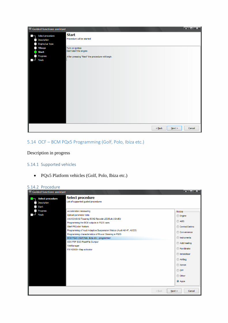
5.14 OCF – BCM PQx5 Programming (Golf, Polo, Ibiza etc.)
Description in progress
5.14.1 Supported vehicles
PQx5 Platform vehicles (Golf, Polo, Ibiza etc.)
5.14.2 Procedure

5.15 OCF – programming characteristics of the Power Assisted Steering control device (Golf 6, Passat,..)
Description in progress
5.15.1 Supported vehicles
PQ35 Platform vehicles (Golf 6, Passat, etc.)

5.15.2 Procedure

5.16 OCF – Acceleration Measurements Description in progress
5.16.1 Supported vehicles List in progress
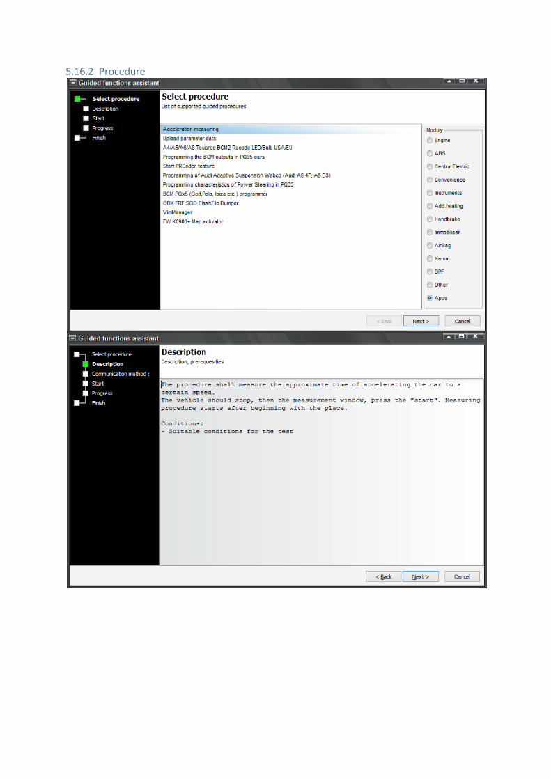
5.16.2 Procedure
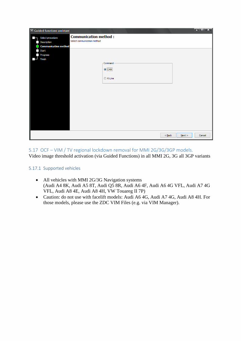
5.17 OCF – VIM / TV regional lockdown removal for MMI 2G/3G/3GP models. Video image threshold activation (via Guided Functions) in all MMI 2G, 3G all 3GP variants
5.17.1 Supported vehicles
All vehicles with MMI 2G/3G Navigation systems
(Audi A4 8K, Audi A5 8T, Audi Q5 8R, Audi A6 4F, Audi A6 4G VFL, Audi A7 4G
VFL, Audi A8 4E, Audi A8 4H, VW Touareg II 7P)
Caution: do not use with facelift models: Audi A6 4G, Audi A7 4G, Audi A8 4H. For
those models, please use the ZDC VIM Files (e.g. via VIM Manager).
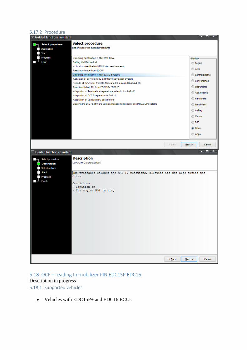
5.17.2 Procedure
5.18 OCF – reading Immobilizer PIN EDC15P EDC16 Description in progress
5.18.1 Supported vehicles
Vehicles with EDC15P+ and EDC16 ECUs
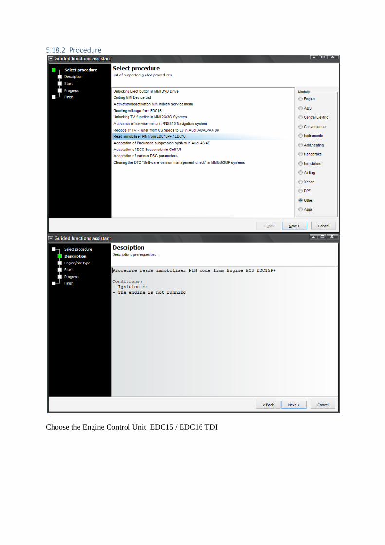
5.18.2 Procedure
Choose the Engine Control Unit: EDC15 / EDC16 TDI
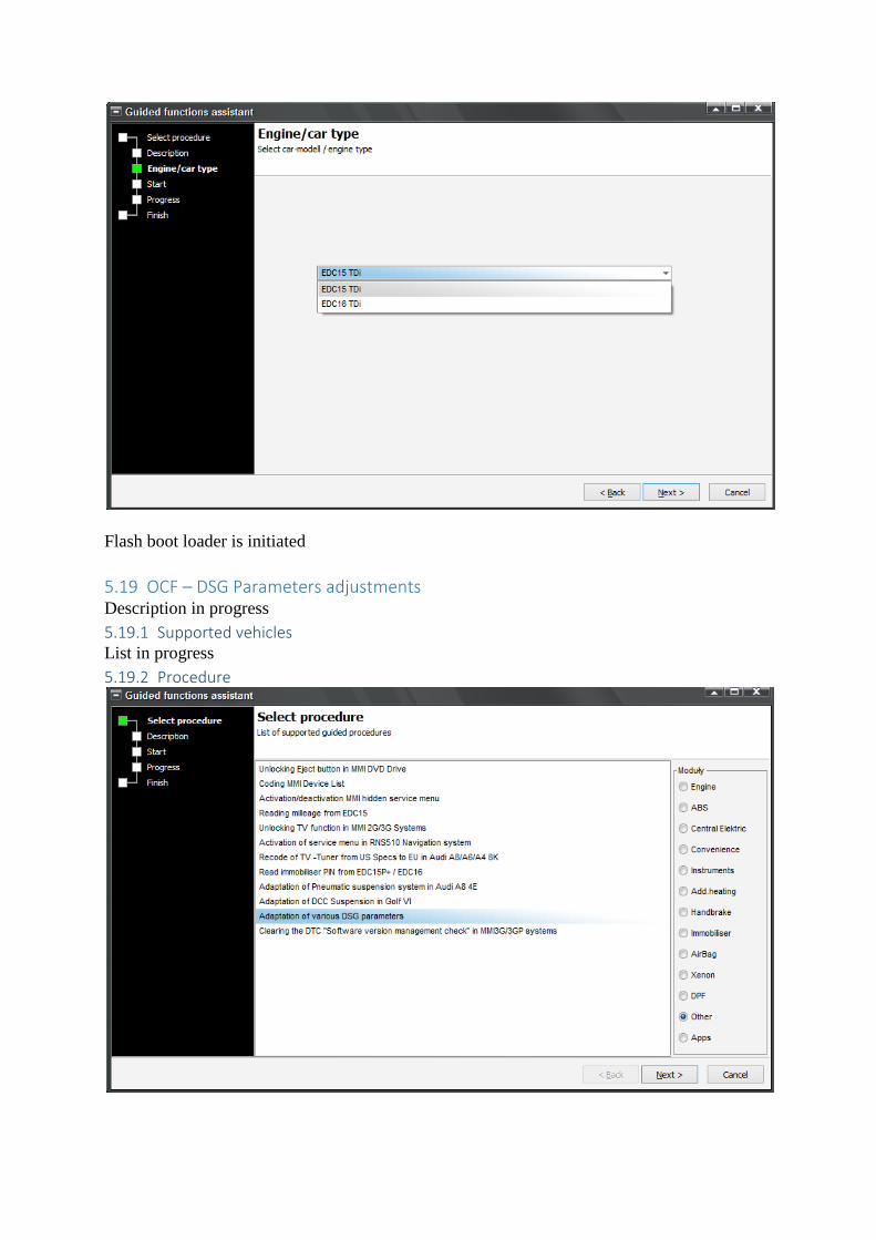
Flash boot loader is initiated
5.19 OCF – DSG Parameters adjustments Description in progress
5.19.1 Supported vehicles List in progress
5.19.2 Procedure
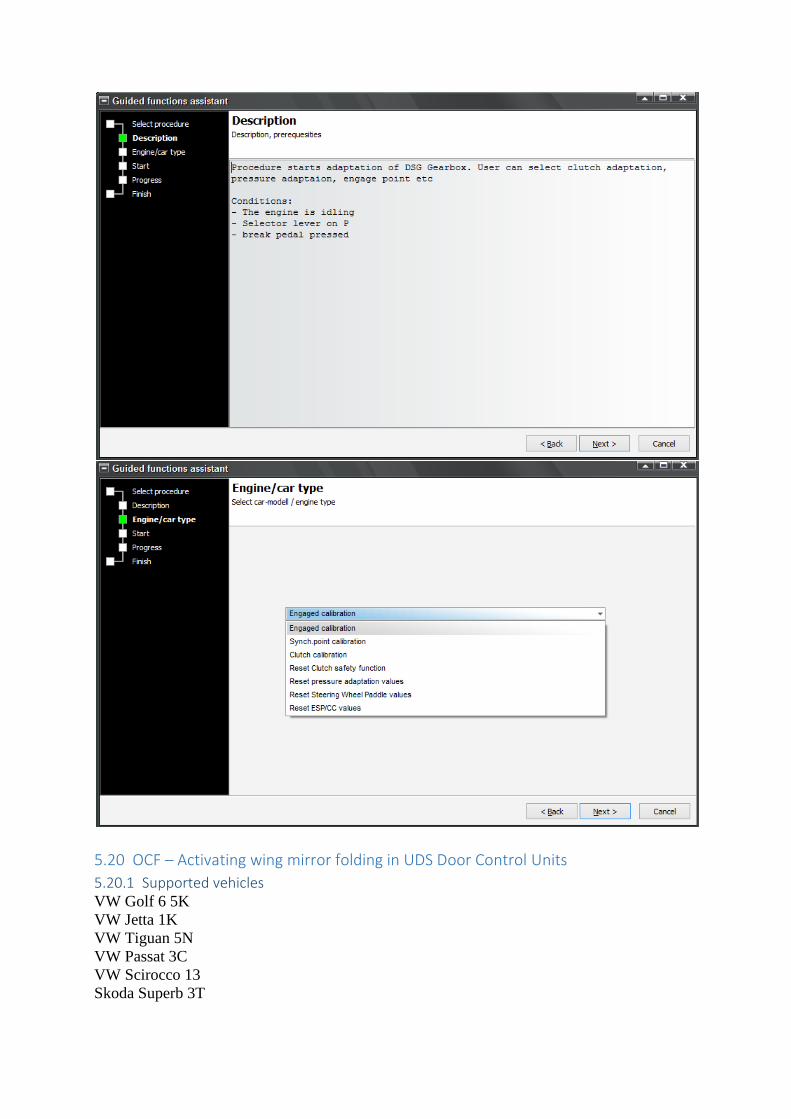
5.20 OCF – Activating wing mirror folding in UDS Door Control Units
5.20.1 Supported vehicles VW Golf 6 5K
VW Jetta 1K
VW Tiguan 5N
VW Passat 3C
VW Scirocco 13
Skoda Superb 3T
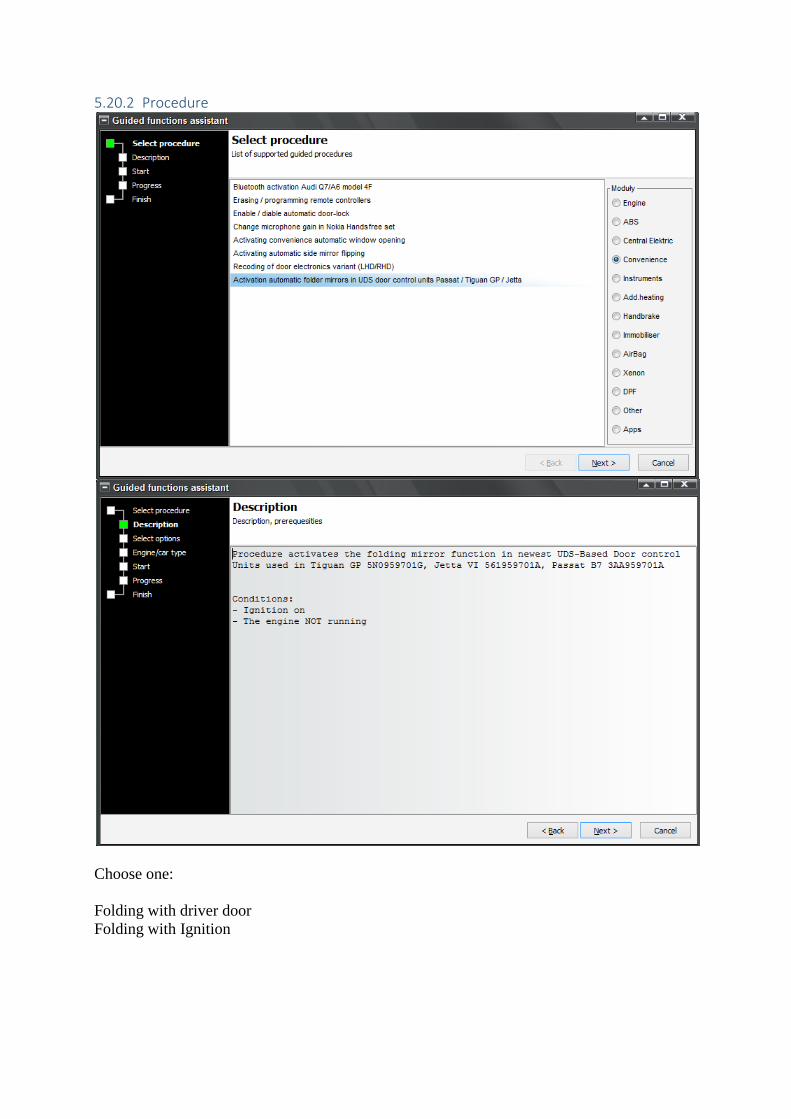
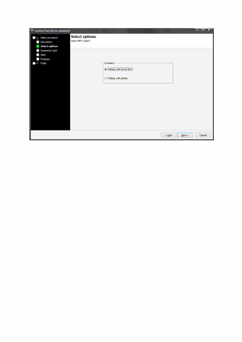
5.20.2 Procedure
Choose one:
Folding with driver door
Folding with Ignition
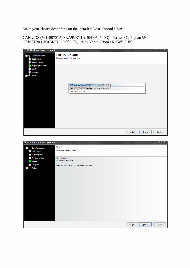
Make your choice depending on the installed Door Control Unit:
CAN UDS (561959701A, 3AA959701A, 5N0959701G) – Passat 3C, Tiguan 5N
CAN TP20 (1K0/5K0) – Golf 6 5K, Jetta / Vento / Bora 1K, Golf 5 1K
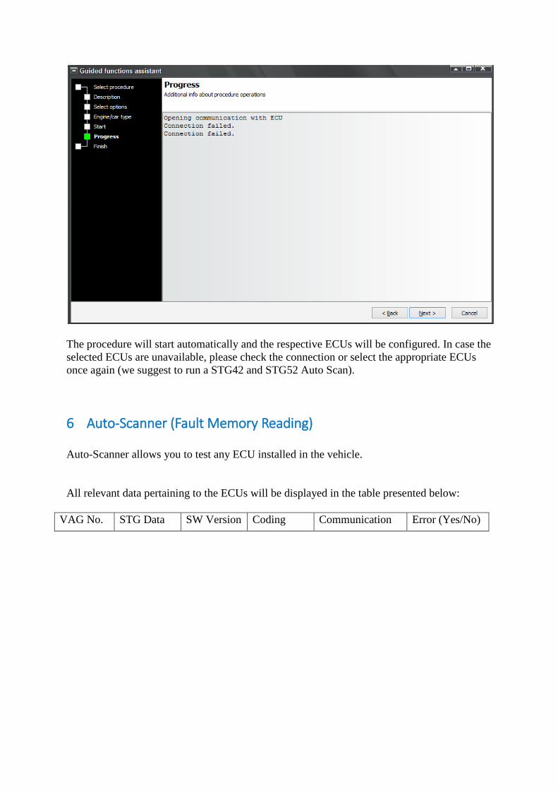
The procedure will start automatically and the respective ECUs will be configured. In case the
selected ECUs are unavailable, please check the connection or select the appropriate ECUs
once again (we suggest to run a STG42 and STG52 Auto Scan).
6 Auto-Scanner (Fault Memory Reading)
Auto-Scanner allows you to test any ECU installed in the vehicle.
All relevant data pertaining to the ECUs will be displayed in the table presented below:
VAG No. STG Data SW Version Coding Communication Error (Yes/No)
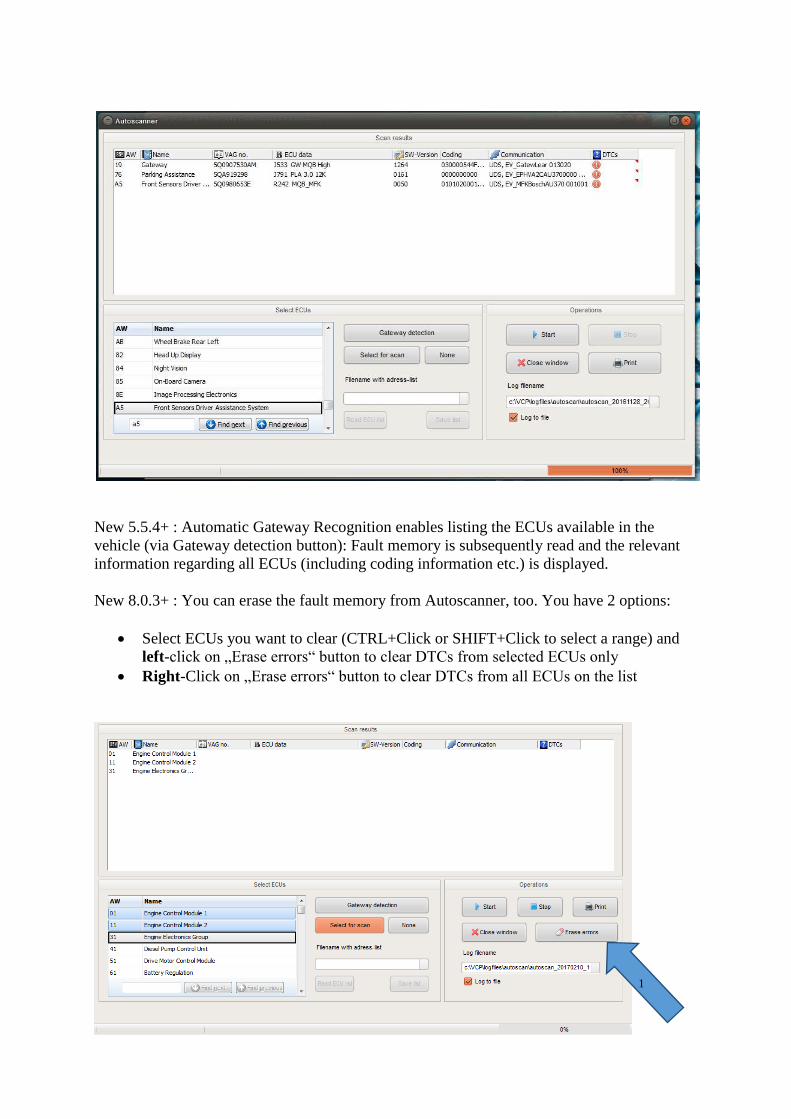
New 5.5.4+ : Automatic Gateway Recognition enables listing the ECUs available in the
vehicle (via Gateway detection button): Fault memory is subsequently read and the relevant
information regarding all ECUs (including coding information etc.) is displayed.
New 8.0.3+ : You can erase the fault memory from Autoscanner, too. You have 2 options:
Select ECUs you want to clear (CTRL+Click or SHIFT+Click to select a range) and
left-click on „Erase errors“ button to clear DTCs from selected ECUs only
Right-Click on „Erase errors“ button to clear DTCs from all ECUs on the list
1
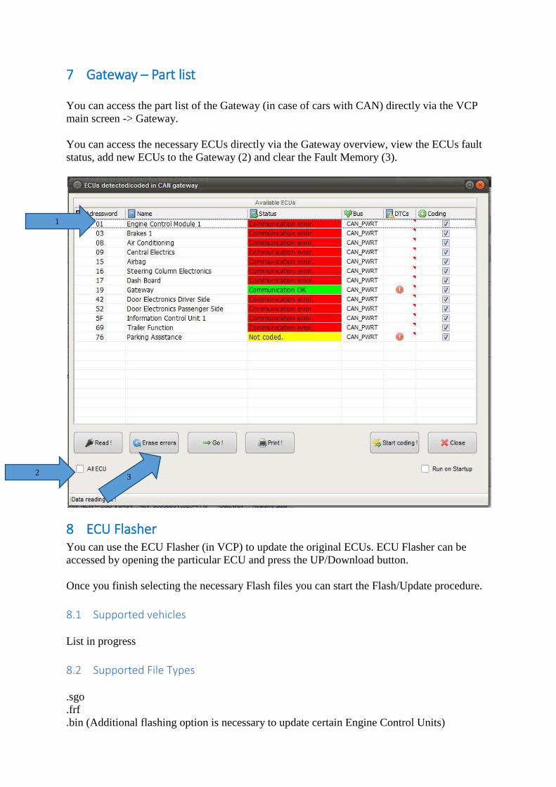
7 Gateway – Part list
You can access the part list of the Gateway (in case of cars with CAN) directly via the VCP
main screen -> Gateway.
You can access the necessary ECUs directly via the Gateway overview, view the ECUs fault
status, add new ECUs to the Gateway (2) and clear the Fault Memory (3).
8 ECU Flasher You can use the ECU Flasher (in VCP) to update the original ECUs. ECU Flasher can be
accessed by opening the particular ECU and press the UP/Download button.
Once you finish selecting the necessary Flash files you can start the Flash/Update procedure.
8.1 Supported vehicles
List in progress
8.2 Supported File Types
.sgo
.frf
.bin (Additional flashing option is necessary to update certain Engine Control Units)
1
3 2
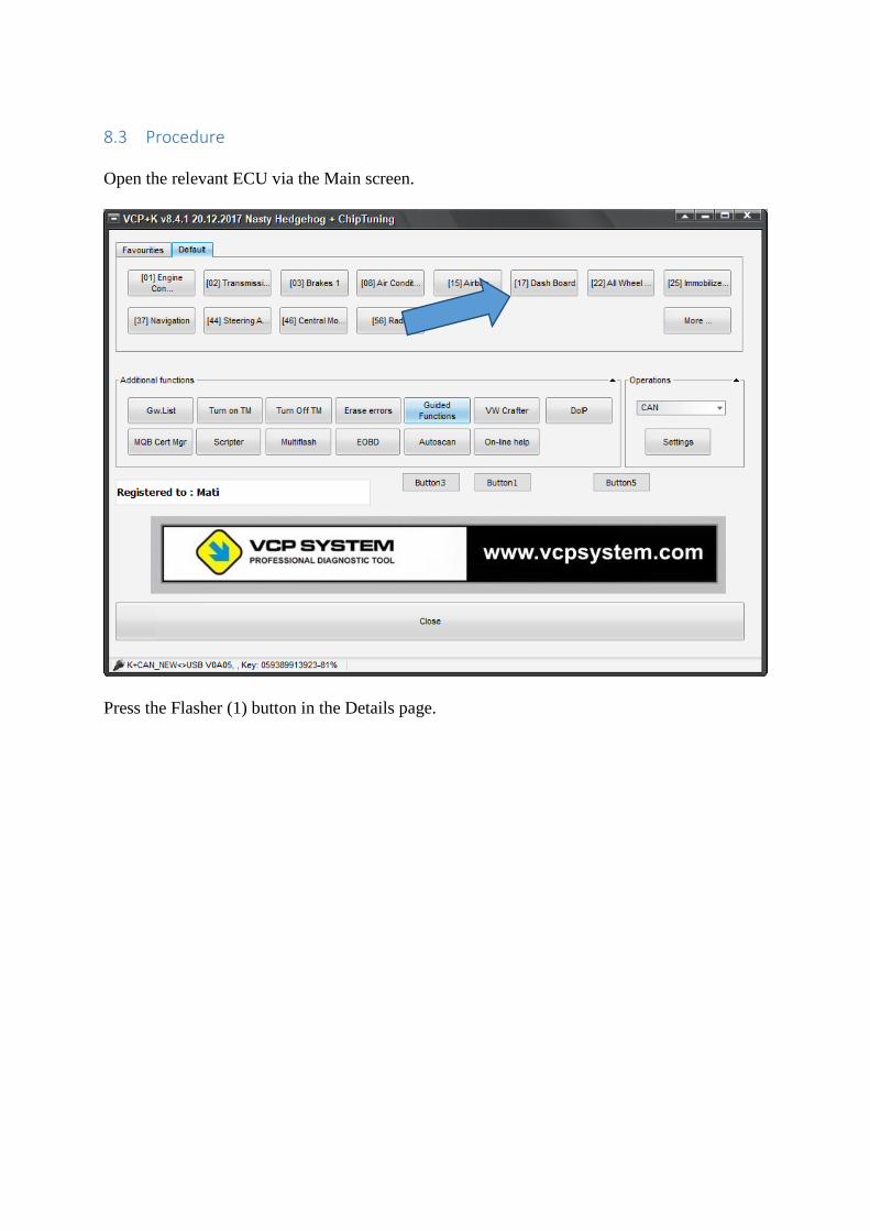
8.3 Procedure
Open the relevant ECU via the Main screen.
Press the Flasher (1) button in the Details page.
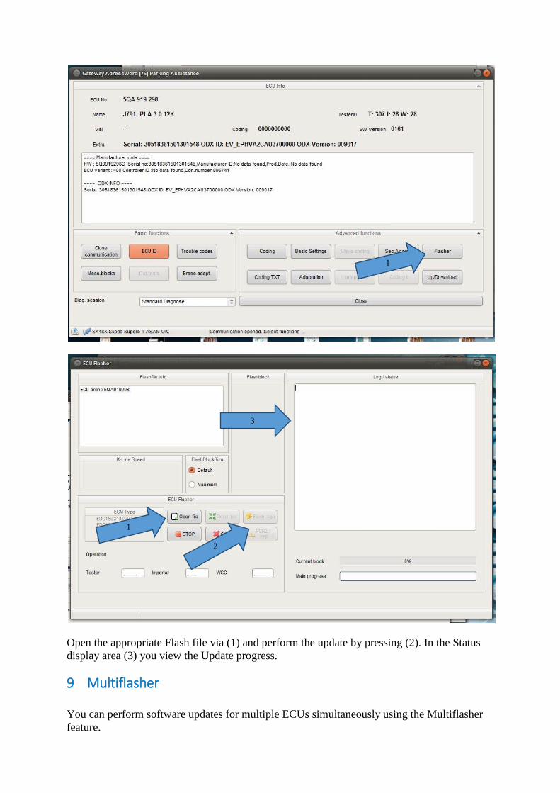
Open the appropriate Flash file via (1) and perform the update by pressing (2). In the Status
display area (3) you view the Update progress.
9 Multiflasher
You can perform software updates for multiple ECUs simultaneously using the Multiflasher
feature.
1
2
1
3
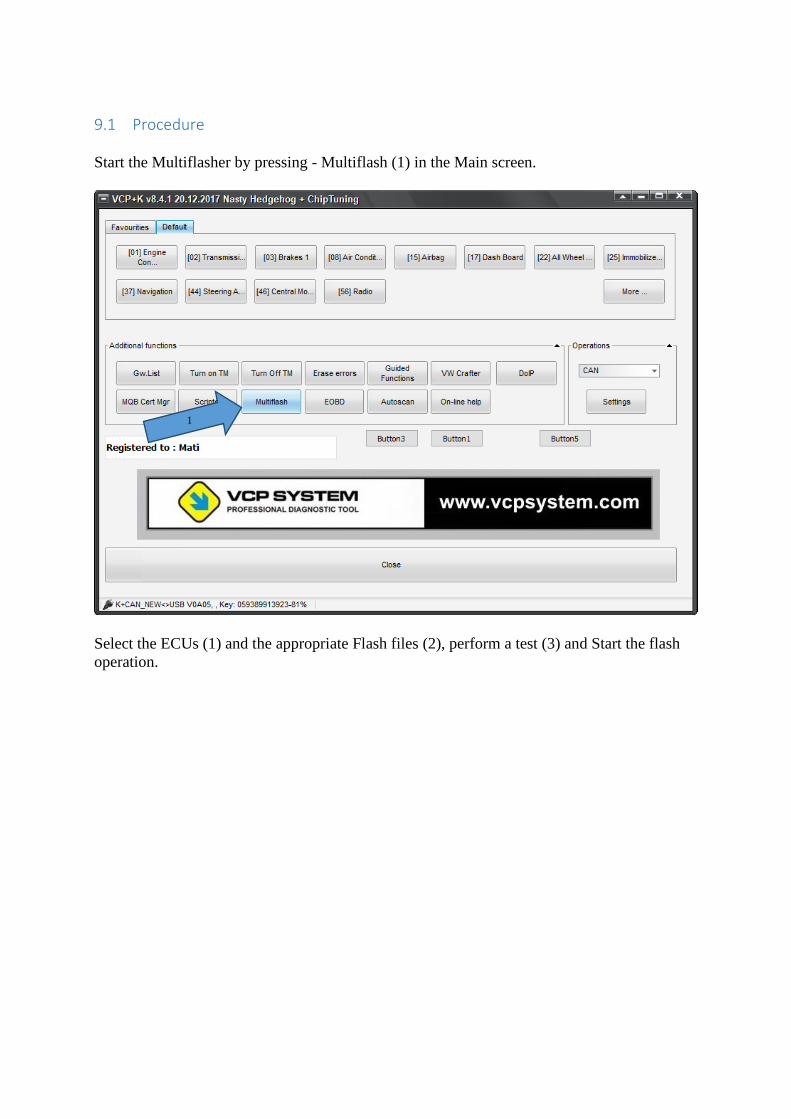
9.1 Procedure
Start the Multiflasher by pressing - Multiflash (1) in the Main screen.
Select the ECUs (1) and the appropriate Flash files (2), perform a test (3) and Start the flash
operation.
1
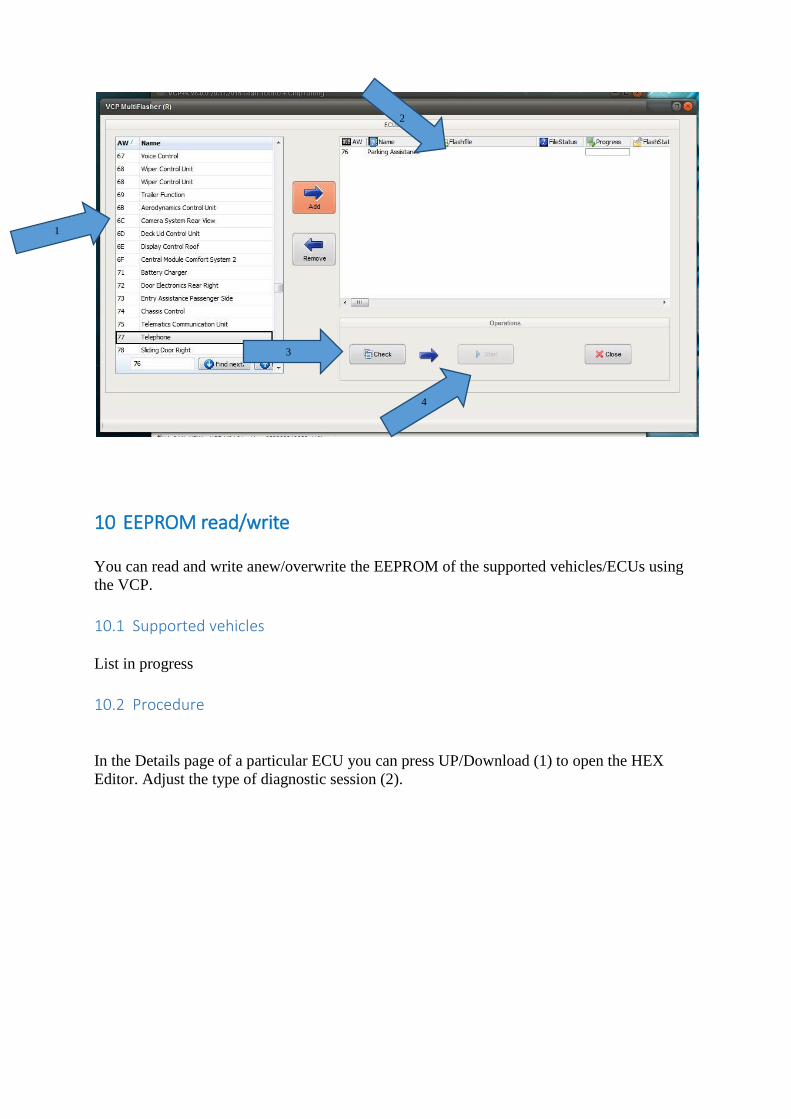
10 EEPROM read/write
You can read and write anew/overwrite the EEPROM of the supported vehicles/ECUs using
the VCP.
10.1 Supported vehicles
List in progress
10.2 Procedure
In the Details page of a particular ECU you can press UP/Download (1) to open the HEX
Editor. Adjust the type of diagnostic session (2).
2
1
3
4
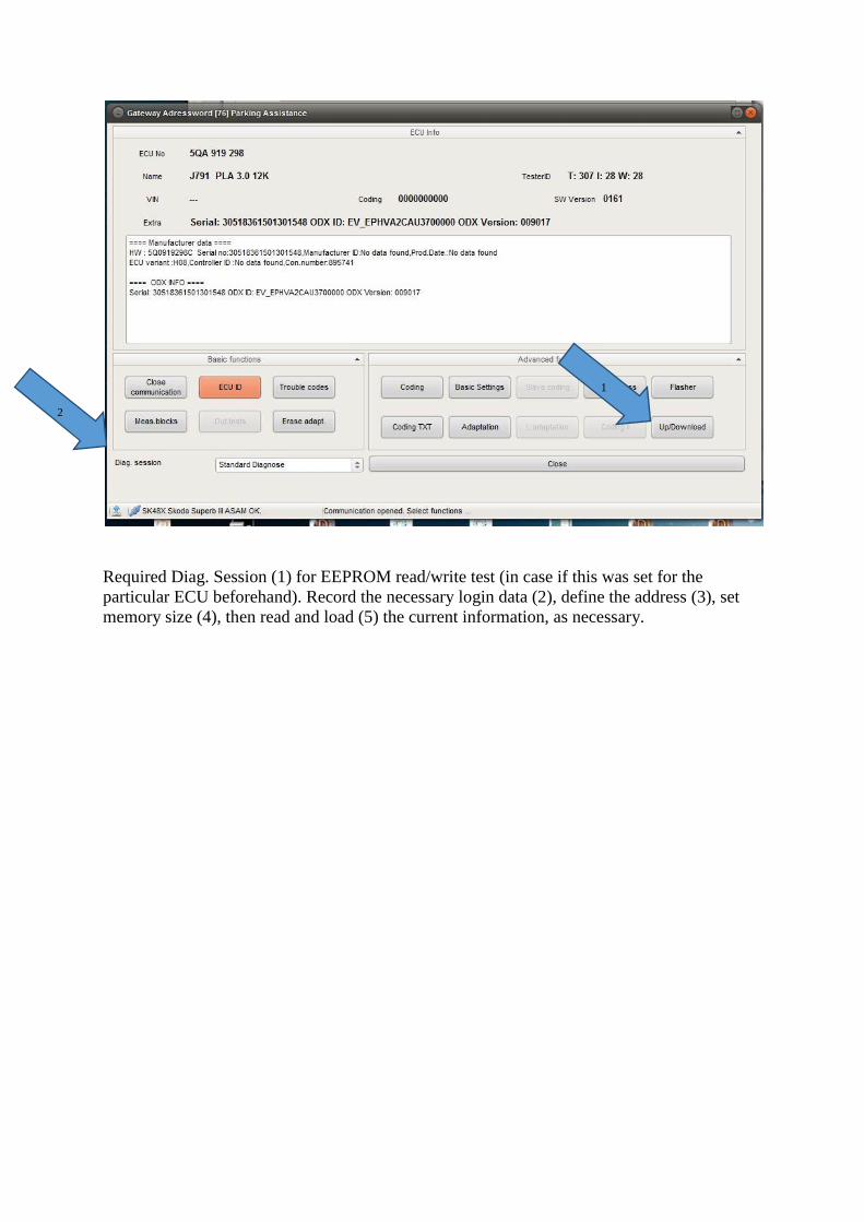
Required Diag. Session (1) for EEPROM read/write test (in case if this was set for the
particular ECU beforehand). Record the necessary login data (2), define the address (3), set
memory size (4), then read and load (5) the current information, as necessary.
1
2
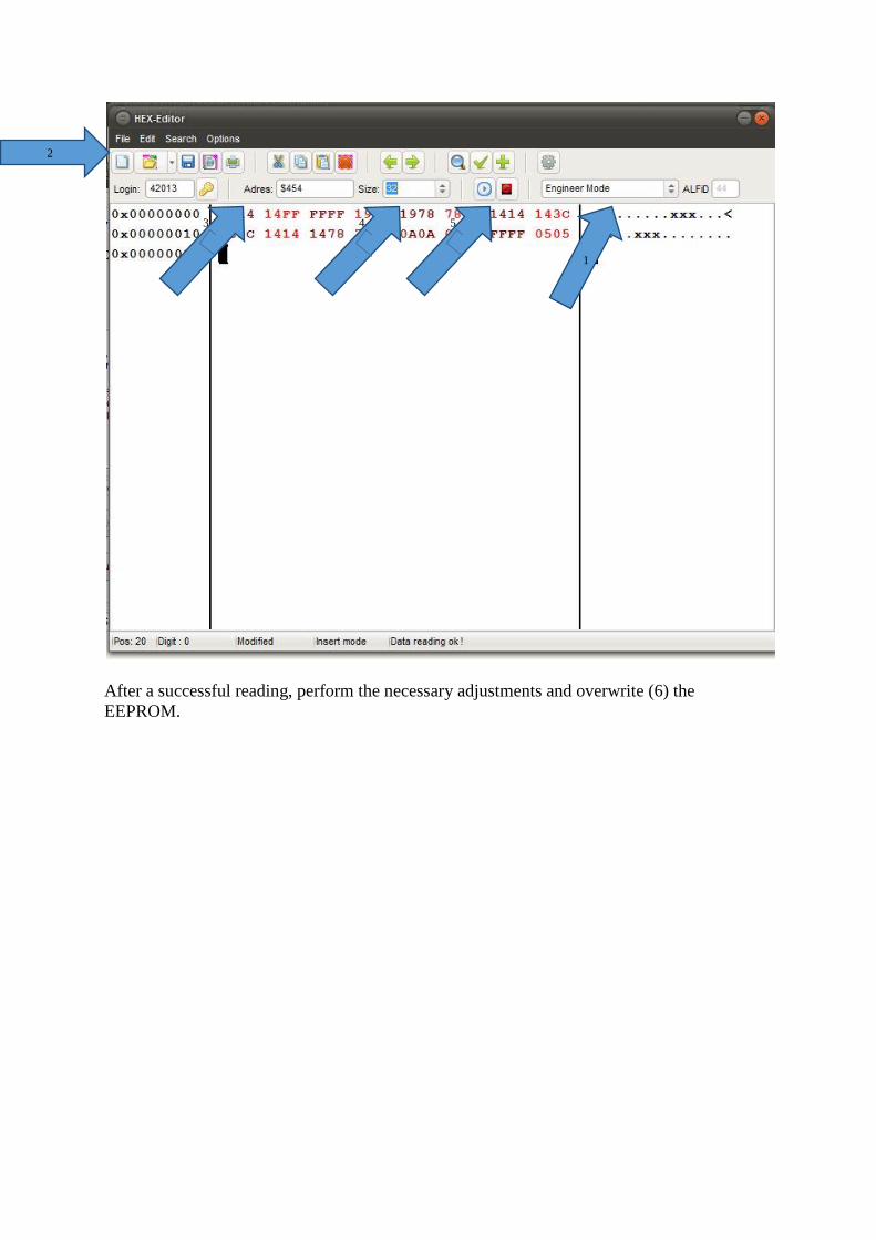
After a successful reading, perform the necessary adjustments and overwrite (6) the
EEPROM.
1
3
2
4
5
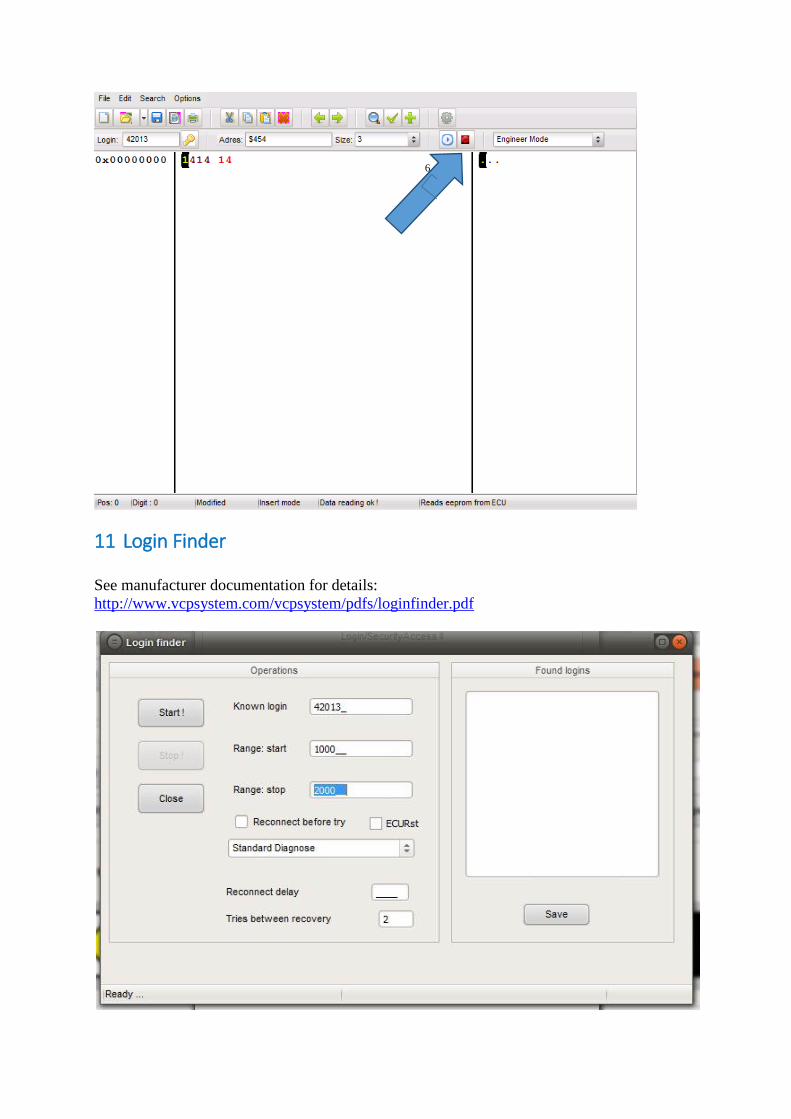
11 Login Finder
See manufacturer documentation for details:
http://www.vcpsystem.com/vcpsystem/pdfs/loginfinder.pdf
6
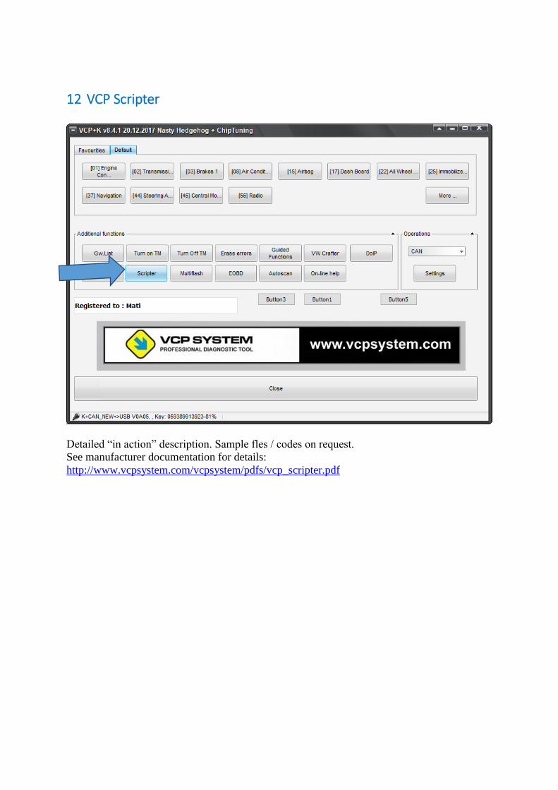
12 VCP Scripter
Detailed “in action” description. Sample fles / codes on request.
See manufacturer documentation for details:
http://www.vcpsystem.com/vcpsystem/pdfs/vcp_scripter.pdf
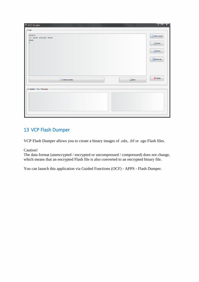
13 VCP Flash Dumper
VCP Flash Dumper allows you to create a binary images of .odx, .frf or .sgo Flash files.
Caution!
The data format (unencrypted / encrypted or uncompressed / compressed) does not change,
which means that an encrypted Flash file is also converted to an encrypted binary file.
You can launch this application via Guided Functions (OCF) - APPS - Flash Dumper.
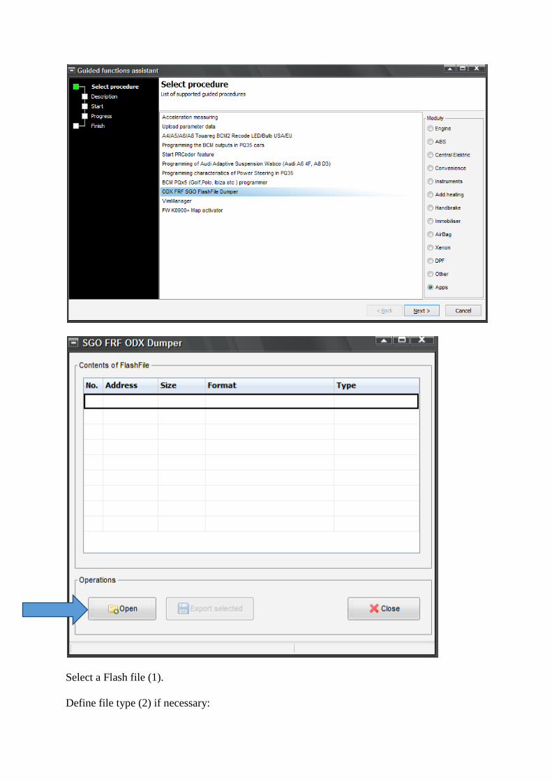
Select a Flash file (1).
Define file type (2) if necessary:
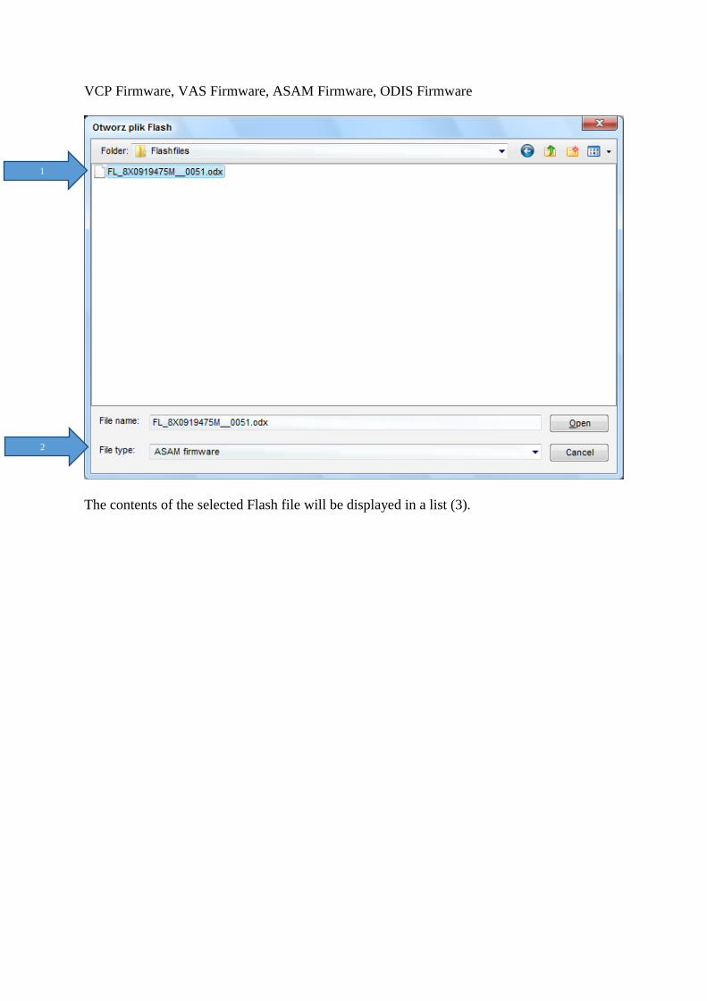
VCP Firmware, VAS Firmware, ASAM Firmware, ODIS Firmware
The contents of the selected Flash file will be displayed in a list (3).
1
2
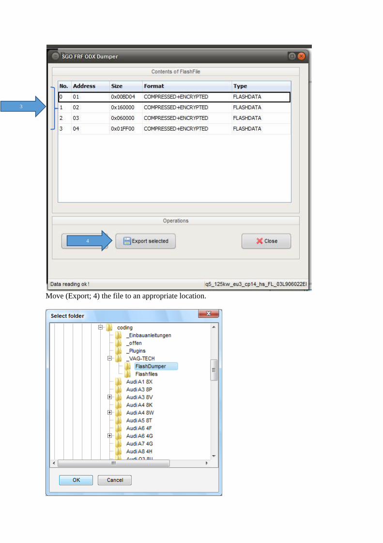
Move (Export; 4) the file to an appropriate location.
3
4
It will be stored as a .BIN file and can be edited as necessary.
14 Sample coding
Below, you find examples of codes which will show you the basics of coding and the specific
features of VCP.
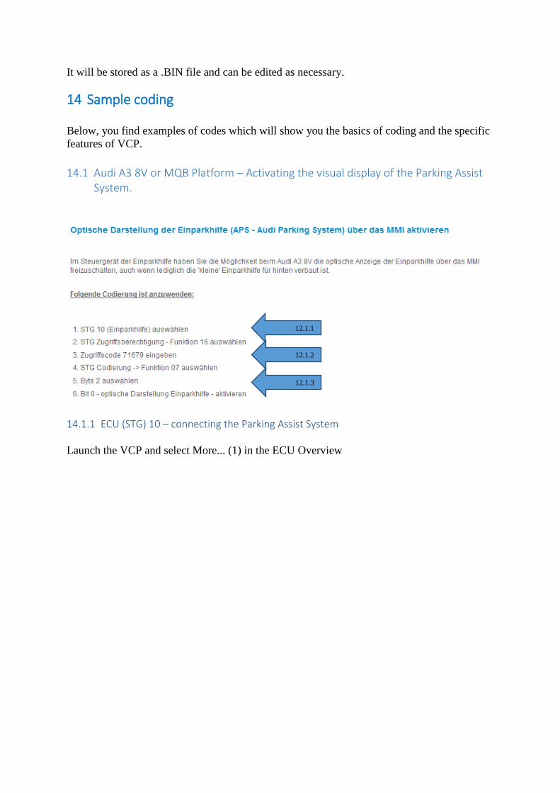
14.1 Audi A3 8V or MQB Platform – Activating the visual display of the Parking Assist System.
14.1.1 ECU (STG) 10 – connecting the Parking Assist System
Launch the VCP and select More... (1) in the ECU Overview
12.1.1
12.1.2
12.1.3
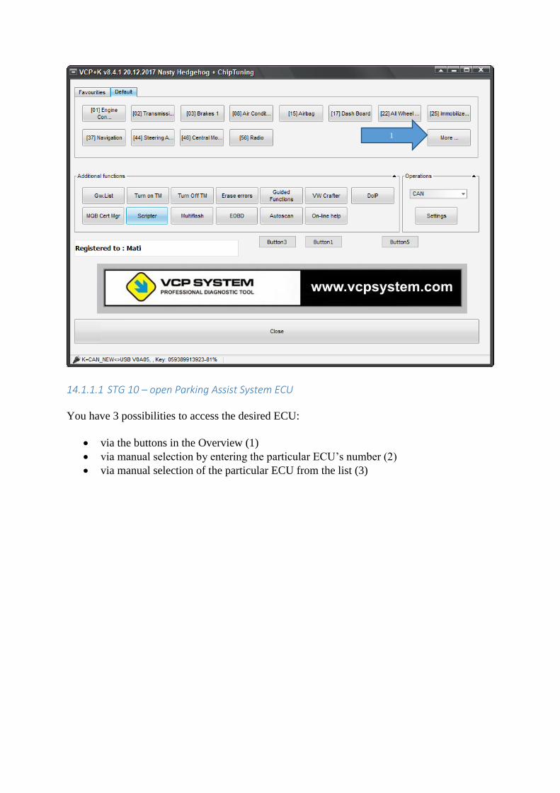
14.1.1.1 STG 10 – open Parking Assist System ECU
You have 3 possibilities to access the desired ECU:
via the buttons in the Overview (1)
via manual selection by entering the particular ECU’s number (2)
via manual selection of the particular ECU from the list (3)
1
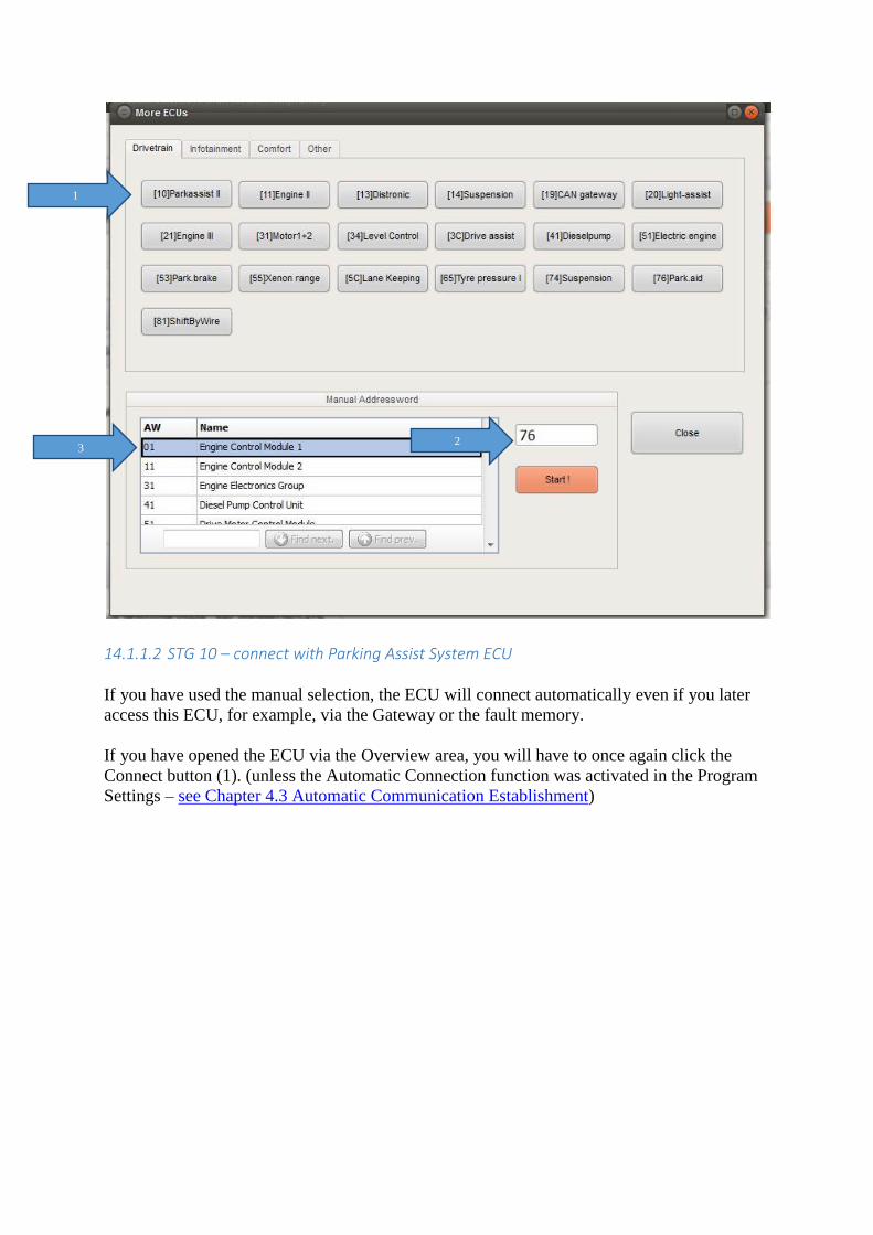
14.1.1.2 STG 10 – connect with Parking Assist System ECU
If you have used the manual selection, the ECU will connect automatically even if you later
access this ECU, for example, via the Gateway or the fault memory.
If you have opened the ECU via the Overview area, you will have to once again click the
Connect button (1). (unless the Automatic Connection function was activated in the Program
Settings – see Chapter 4.3 Automatic Communication Establishment)
1
2 3
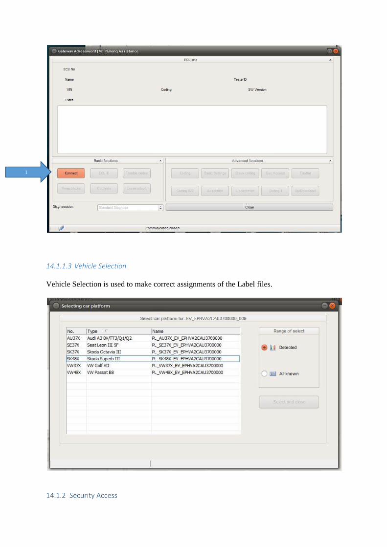
14.1.1.3 Vehicle Selection
Vehicle Selection is used to make correct assignments of the Label files.
14.1.2 Security Access
1
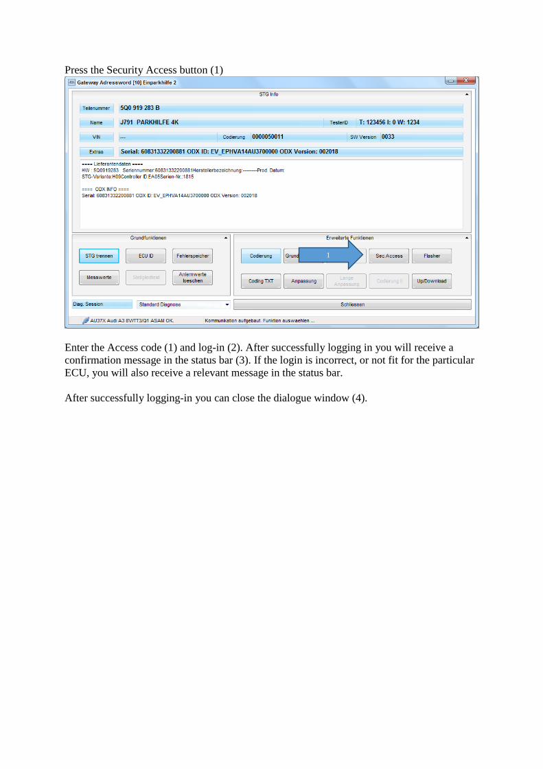
Press the Security Access button (1)
Enter the Access code (1) and log-in (2). After successfully logging in you will receive a
confirmation message in the status bar (3). If the login is incorrect, or not fit for the particular
ECU, you will also receive a relevant message in the status bar.
After successfully logging-in you can close the dialogue window (4).
1
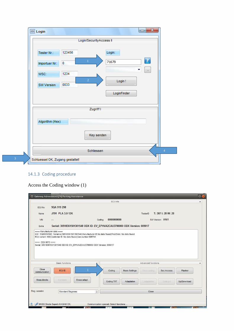
14.1.3 Coding procedure
Access the Coding window (1)
1
2
3
4
1
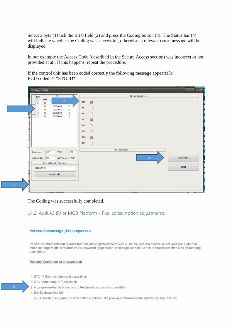
Select a byte (1) tick the Bit 0 field (2) and press the Coding button (3). The Status bar (4)
will indicate whether the Coding was successful, otherwise, a relevant error message will be
displayed.
In our example the Access Code (described in the Secure Access section) was incorrect or not
provided at all. If this happens, repeat the procedure.
If the control unit has been coded correctly the following message appears(5):
ECU coded -> *STG ID*
The Coding was successfully completed.
14.2 Audi A3 8V or MQB Platform – Fuel consumption adjustments
1
2
3
4
5
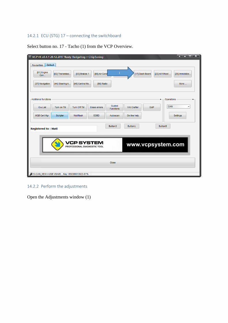
14.2.1 ECU (STG) 17 – connecting the switchboard
Select button no. 17 - Tacho (1) from the VCP Overview.
14.2.2 Perform the adjustments
Open the Adjustments window (1)
1
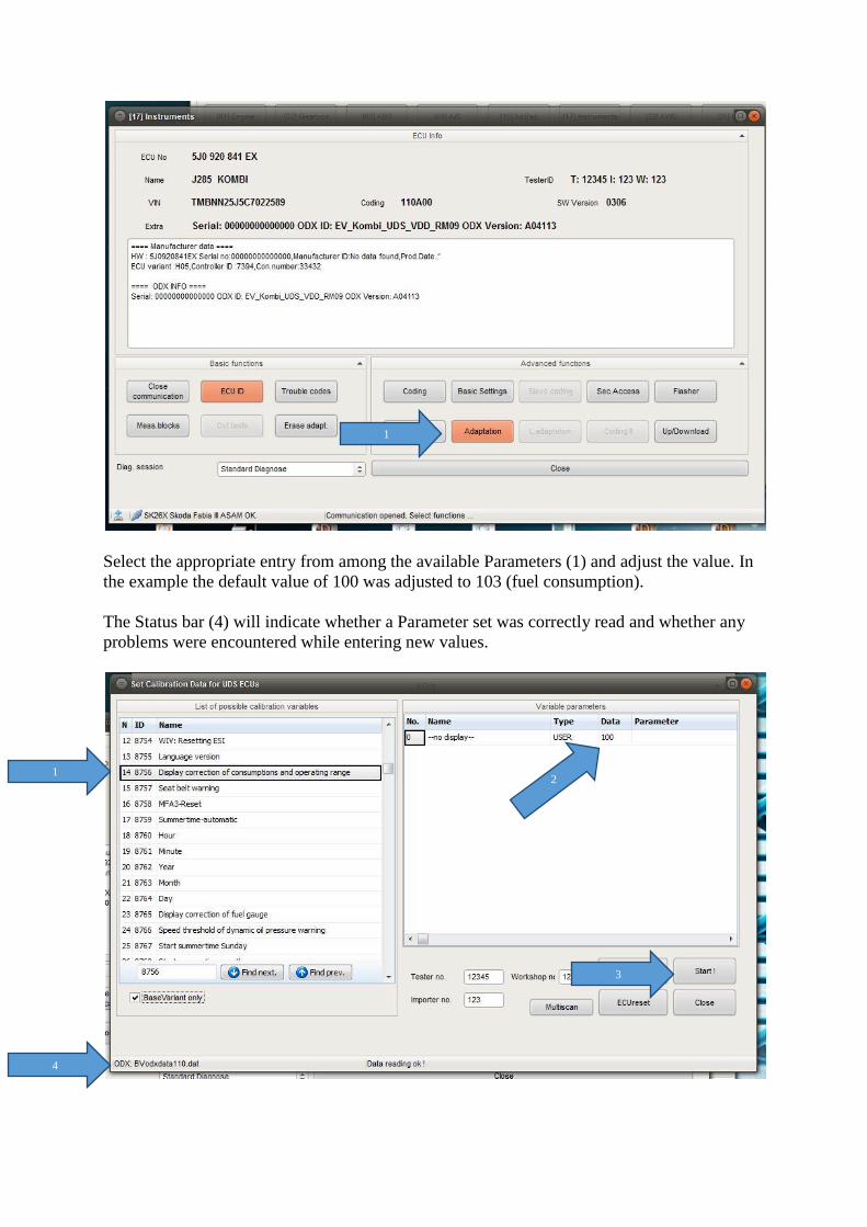
Select the appropriate entry from among the available Parameters (1) and adjust the value. In
the example the default value of 100 was adjusted to 103 (fuel consumption).
The Status bar (4) will indicate whether a Parameter set was correctly read and whether any
problems were encountered while entering new values.
1
1 2
3
4
15 Problems / Troubleshooting
15.1 Activator cannot start If after upgrading from version 4.4 to 4.6(after initial installation) the Activator cannot launch
anymore, please download the most up to date version of Activator from:
http://www.vcpsystem.com/vcpsystem/card/vcpactivator7.exe
Copy the file to your local VCP directory (C:\VCP) and replace the current existing file.
This should solve the problem, and you should be able to use the Activator version 4.6
without any issues.
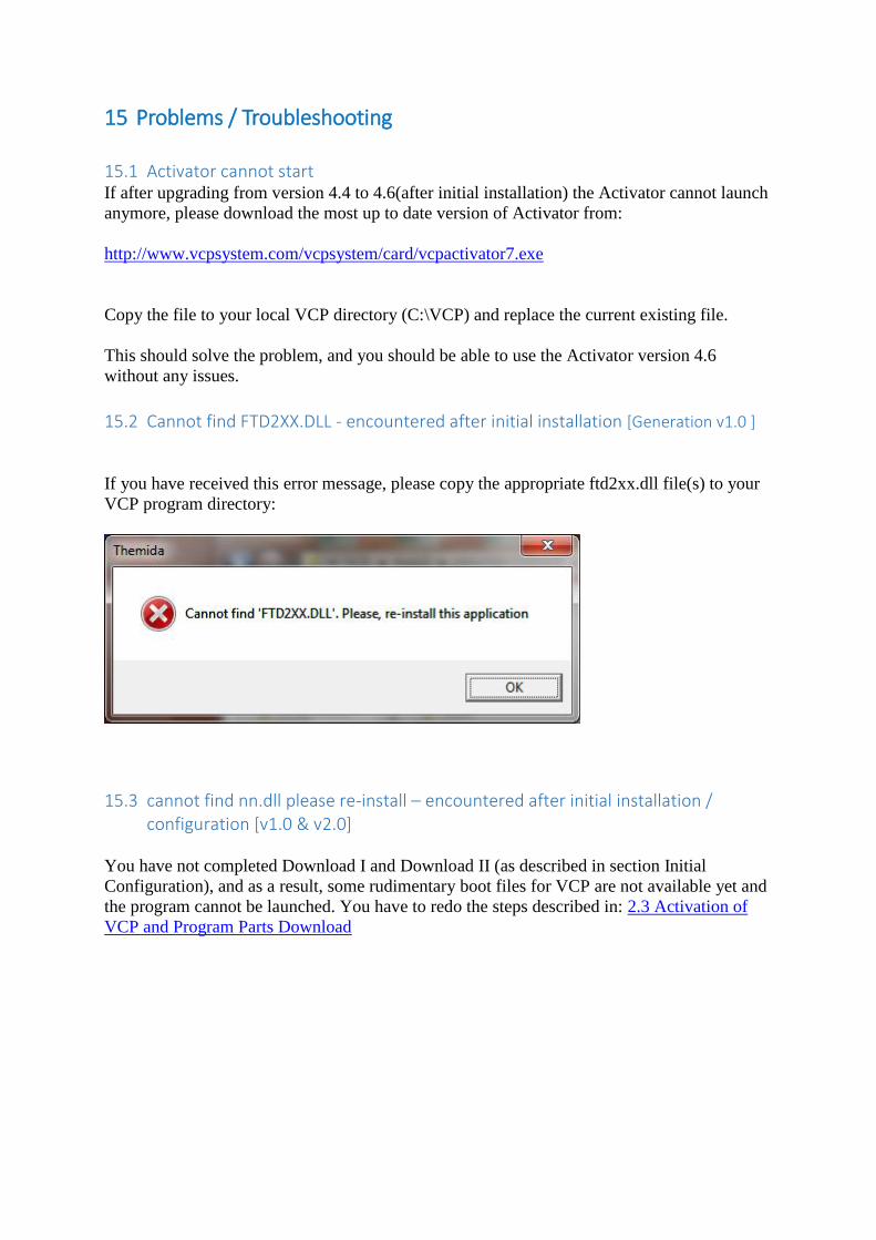
15.2 Cannot find FTD2XX.DLL - encountered after initial installation [Generation v1.0 ]
If you have received this error message, please copy the appropriate ftd2xx.dll file(s) to your
VCP program directory:
15.3 cannot find nn.dll please re-install – encountered after initial installation / configuration [v1.0 & v2.0]
You have not completed Download I and Download II (as described in section Initial
Configuration), and as a result, some rudimentary boot files for VCP are not available yet and
the program cannot be launched. You have to redo the steps described in: 2.3 Activation of
VCP and Program Parts Download
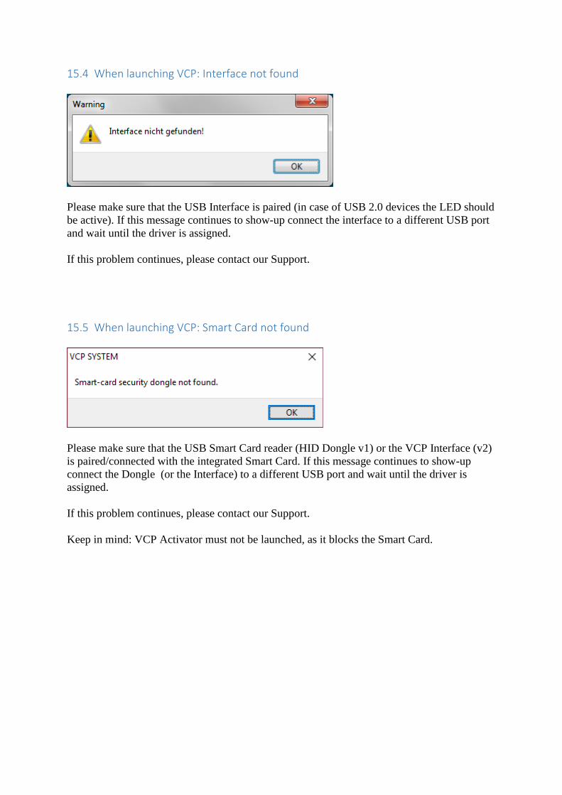
15.4 When launching VCP: Interface not found
Please make sure that the USB Interface is paired (in case of USB 2.0 devices the LED should
be active). If this message continues to show-up connect the interface to a different USB port
and wait until the driver is assigned.
If this problem continues, please contact our Support.
15.5 When launching VCP: Smart Card not found
Please make sure that the USB Smart Card reader (HID Dongle v1) or the VCP Interface (v2)
is paired/connected with the integrated Smart Card. If this message continues to show-up
connect the Dongle (or the Interface) to a different USB port and wait until the driver is
assigned.
If this problem continues, please contact our Support.
Keep in mind: VCP Activator must not be launched, as it blocks the Smart Card.