version 2017 release notes - avl notes tmexcite v2017 avl list gmbh hans-list-platz 1, a-8020 graz,...
TRANSCRIPT

Version 2017
Release Notes


Release Notes EXCITETM v2017
AVL LIST GmbH Hans-List-Platz 1, A-8020 Graz, Austria http://www.avl.com
AST Local Support Contact: www.avl.com/ast-worldwide
Revision Date Description Document No.
A 30-Apr-2009 EXCITE v2009 - Release Notes 06.0101.2009
B 17-Jul-2009 EXCITE v2009.1 - Release Notes 06.0101.2009.1
C 30-Nov-2009 EXCITE v2009.2 - Release Notes 06.0101.2009.2
D 30-Mar-2010 EXCITE v2009.3 - Release Notes 06.0101.2009.3
E 19-Nov-2010 EXCITE v2010 - Release Notes 06.0101.2010
F 25-Mar-2011 EXCITE v2010.1 - Release Notes 06.0101.2010.1
G 29-Jul-2011 EXCITE v2011 - Release Notes 06.0101.2011
H 02-Dec-2011 EXCITE v2011.1 - Release Notes 06.0101.2011.1
I 16-May-2012 EXCITE v2011.2 - Release Notes 06.0101.2011.2
J 20-July-2012 EXCITE v2011.2.1 - Release Notes 06.0101.2011.2.1
K 25-Jan-2013 EXCITE v2013 - Release Notes 06.0101.2013
L 17-June-2013 EXCITE v2013.1 - Release Notes 06.0101.2013.1
M 15-Nov-2013 EXCITE v2013.2 - Release Notes 06.0101.2013.2
N 15-May-2014 EXCITE v2014 - Release Notes 06.0101.2014
O 28-Feb-2015 EXCITE v2014.1 - Release Notes 06.0101.2014.1
P 26-Feb-2016 EXCITE v2016 - Release Notes 06.0101.2016
Q 28-Feb-2017 EXCITETM
v2017 - Release Notes 06.0101.2017
Copyright © 2017, AVL
All rights reserved. No part of this publication may be reproduced, transmitted, transcribed, stored
in a retrieval system, or translated into any language or computer language in any form or by any
means, electronic, mechanical, magnetic, optical, chemical, manual or otherwise, without prior
written consent of AVL.
This document describes how to run the EXCITETM
software. It does not attempt to discuss all the
concepts required to obtain successful solutions. It is the user’s responsibility to determine if
he/she has sufficient knowledge and understanding of structural dynamics to apply this software
appropriately.
This software and document are distributed solely on an "as is" basis. The entire risk as to their
quality and performance is with the user. Should either the software or this document prove
defective, the user assumes the entire cost of all necessary servicing, repair, or correction. AVL and
its distributors will not be liable for direct, indirect, incidental or consequential damages resulting
from any defect in the software or this document, even if they have been advised of the possibility
of such damage.
EXCITETM
is a trademark of AVL LIST. EXCITETM
will be referred as EXCITE in this manual.
The names of the software and hardware products used in this manual are mostly the respective
trademarks or registered trademarks of their companies.


Release Notes EXCITETM v2017
AST.06.0101.2017 - 28-Feb-2017 i
Table of Contents
1. Release v2017 ____________________________________________________ 1-1
1.1. EXCITE Power Unit __________________________________________________________ 1-1
1.1.1. New Features ____________________________________________________________ 1-1
1.1.1.1. Valve Train Component ________________________________________________ 1-1
1.1.1.2. Automatic Generation of Retained Nodes for Flexible Advanced Cylindrical
Gear Joint (FlexACYG) ________________________________________________ 1-3
1.1.1.3. Simple Hypoid Gear Based on Maps Created by Tooth Contact Analysis
(TCA) (beta-feature) ___________________________________________________ 1-4
1.1.1.4. Advanced Cylindrical Gear Joint: Visualization of Contact patterns at
flank-surfaces (Engagement Field Plots) _________________________________ 1-5
1.1.1.5. Rolling Element Bearing Joint: Import of KISSsys Bearing Data ____________ 1-7
1.1.1.6. Drag Torque and Loss Calculation in Clutch Joint ________________________ 1-8
1.1.1.7. EHD Contact – Non-stationary Heat Balance including Boundary Structures 1-9
1.1.1.8. New Property Database _______________________________________________ 1-10
1.1.1.9. New Handling of Node Sets ___________________________________________ 1-10
1.1.1.10. New Utility – Evaluate Web Stiffness __________________________________ 1-12
1.1.1.11. New Preprocessing Script – Convert Total Forces and Moments from
Unbalance to FEM __________________________________________________ 1-14
1.1.2. FE Interface Enhancements ______________________________________________ 1-14
1.1.2.1. Apply External Forces to FE Analysis Task – Dynamic Response Analysis –
Abaqus _____________________________________________________________ 1-14
1.1.2.2. Abaqus 2016 _________________________________________________________ 1-16
1.1.2.3. Ansys 17.2 __________________________________________________________ 1-16
1.1.2.4. MSC Nastran 2014 and 2016 __________________________________________ 1-16
1.1.2.5. NX Nastran 9 and 10 _________________________________________________ 1-16
1.1.2.6. OptiStruct 14.0 ______________________________________________________ 1-16
1.1.2.7. New Support of AVL FIRETM
for Thermal Load Analysis _________________ 1-17
1.1.3. Post-processing Enhancements ____________________________________________ 1-18
1.1.3.1. Piston Report Extensions _____________________________________________ 1-18
1.1.3.2. Tool – Export Case Set Results – Extensions ____________________________ 1-19
1.1.4. Other Enhancements_____________________________________________________ 1-19
1.2. EXCITE Designer ___________________________________________________________ 1-23
1.2.1. New Features ___________________________________________________________ 1-23
1.2.1.1. MB and Web Load: Extended Modeling of Main Bearings and Additional
Results _____________________________________________________________ 1-23
1.2.1.2. Torsion: Potential Energy Distribution in Torsional Modes _______________ 1-25
1.2.2. Enhancements __________________________________________________________ 1-25
1.3. EXCITE Piston&Rings _______________________________________________________ 1-26
1.3.1. Reworking the 3D Ring Dynamics Module __________________________________ 1-26
1.3.2. Enhancement of Ring Dynamics Modeling Approach _________________________ 1-26
1.3.3. Enhancement of GUI Input Data __________________________________________ 1-27
1.3.4. Enhancement of Results Post-Processing and Animation _____________________ 1-27
1.3.5. Storing Data for Thermal Load Calculations ________________________________ 1-28
1.3.1. Enhancements __________________________________________________________ 1-29

EXCITETM v2017 Release Notes
ii AST.06.0101.2017 - 28-Feb-2017
1.4. EXCITE Timing Drive _______________________________________________________ 1-30
1.4.1. Enhancements __________________________________________________________ 1-30
1.5. EXCITE Acoustics ___________________________________________________________ 1-31
1.5.1. New Features ___________________________________________________________ 1-31
1.5.1.1. Customized Color Settings ____________________________________________ 1-31
1.5.1.2. DB Weighting for 3D Sound Pressure Level Results and Audio Files _______ 1-32
1.5.1.3. Show Acoustic Surface ID’s ___________________________________________ 1-32
1.5.1.4. Automatic Mesh File Export ___________________________________________ 1-33
1.5.1.5. Mapped Velocity Visualization _________________________________________ 1-33
1.5.1.6. Sound Power Level (ISO 3745)_________________________________________ 1-34
1.5.1.7. Bar Chart for Octave and 3rd
Octave Bands ______________________________ 1-36
1.5.2. Enhancements __________________________________________________________ 1-36
1.6. EXCITE Pre-processing Tools ________________________________________________ 1-37
1.6.1. Shaft Modeler: New Features _____________________________________________ 1-37
1.6.1.1. Gyroscopic Modal Analysis: Resonances_________________________________ 1-37
1.6.1.2. Modal Analysis of Flexibly Supported Shaft: New Options ________________ 1-37
1.6.1.3. Enhancement ________________________________________________________ 1-38
1.6.2. Autoshaft _______________________________________________________________ 1-38

Release Notes EXCITETM v2017
28-Feb-2017 1-1
1. RELEASE V2017 This document describes the new features and enhancements in AVL Workspace v2017 for
the following:
EXCITETM
Power Unit
EXCITE TM
Designer
EXCITE TM
Piston&Rings
EXCITE TM
Timing Drive
EXCITE TM
Acoustics
Shaft Modeler
AutoSHAFT
Changes described here can also be found in the updated documentation.
Resolved bugs and known issues are now available on the Customer Service Portal. Please
contact your local support to get access.
1.1. EXCITE Power Unit
1.1.1. New Features
1.1.1.1. Valve Train Component
All basic valve train templates, which were introduced in v2016, provide an option for an
extended definition of valve train configuration.
The new configurations allow using hydraulic lash adjuster components – hydraulic insets
for tappets or levers as well as hydraulic support components (“lifters”) for drag levers – in
EXCITE Power Unit valve train models.
Similar to the models of the hydraulic lash adjuster components in EXCITE Timing Drive
the internal representation of the hydraulic lash adjusters considers
their mechanical parts as rigid bodies
the springs in the system and mechanical contacts between the bodies as joints
with stiffness and damping properties
the supply pressure and the pressure changes in supply and working volume

EXCITETM v2017 Release Notes
1-2 28-Feb-2017
oil compressibility variation due to aeration
oil flows through annular gaps and in the check valve
and force transfer from the pressure in the hydraulic volumes to the mechanical
components
In addition to this, valve train configurations with levers and bridge components can be
considered now for “floating” and “guided” bridges. By default, simple elastic
representations of bridges are calculated from some basic geometry input by a modeler.
Similar to the rocker components, users are free to use externally generated (condensed)
body models instead. In this case users have to take care to use the appropriate coordinate
systems to generate the condensed models.
The new configurations result in a significant increase of required input data. To keep the
modelling approach, on the one hand, as simple as possible and on the other hand, provide
enough flexibility, two modelling levels have been introduced:
BASIC level reduces the required input to a minimum. Wherever possible,
reasonable default values are set and the corresponding inputs are hidden from the
working panels in the graphical user interface (most of the joints, for instance).
DETAILED level gives the user access to all required inputs.
Users can switch between the modelling levels whenever they want.
A further extension which has been introduced is the optional consideration of variable
cam/follower contact stiffness. This is mainly used with flat or spherical tappets, where the
effective stiffness in the cam/follower pair may significantly depend on the eccentricity of
the contact point.

Release Notes EXCITETM v2017
28-Feb-2017 1-3
1.1.1.2. Automatic Generation of Retained Nodes for Flexible
Advanced Cylindrical Gear Joint (FlexACYG)
A new Python script “Retained Nodes for FlexACYG” has been developed in order to
automatically generate the retained nodes for the Flexible Advanced Cylindrical Gear Joint.
In contrast to the standard simulation where the nodes are located at the rotation axis, in
the case of FlexACYG the wheel body is considered as a full flexible body by using
circumferential retained nodes placed close to the root area of each individual tooth.
Significant effort may be required to generate these nodes manually, whereas it can be
done within a few minutes by using the Python script.
In a first step only the mesh file of the gear and its unit system have to be defined. After
starting the script, it tries to determine all relevant gear properties automatically. If for
some reason (e.g. poor quality of the mesh) no values or a wrong value for a particular
property is found, the user is able to define or overwrite it by editing a so-called session file
and rerun the script.
It ends up with the newly generated retained nodes and their connection to the FEM
structure.
EXCITETM v2017 Release Notes
1-4 28-Feb-2017
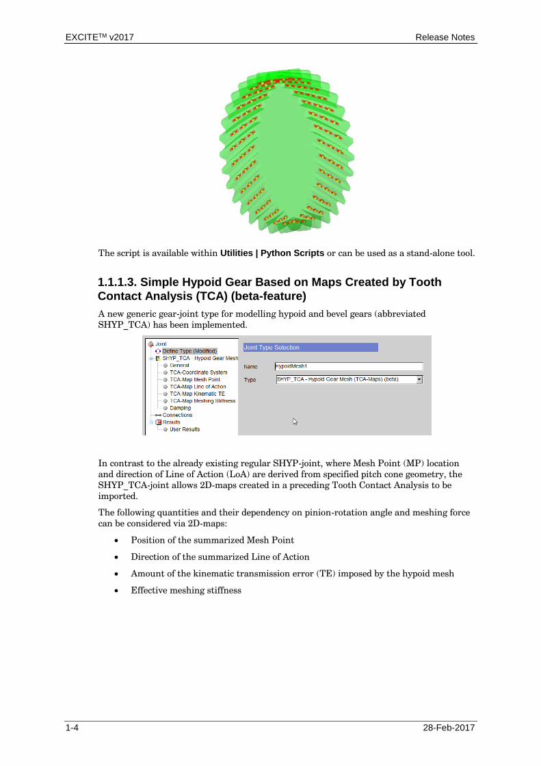
The script is available within Utilities | Python Scripts or can be used as a stand-alone tool.
1.1.1.3. Simple Hypoid Gear Based on Maps Created by Tooth
Contact Analysis (TCA) (beta-feature)
A new generic gear-joint type for modelling hypoid and bevel gears (abbreviated
SHYP_TCA) has been implemented.
In contrast to the already existing regular SHYP-joint, where Mesh Point (MP) location
and direction of Line of Action (LoA) are derived from specified pitch cone geometry, the
SHYP_TCA-joint allows 2D-maps created in a preceding Tooth Contact Analysis to be
imported.
The following quantities and their dependency on pinion-rotation angle and meshing force
can be considered via 2D-maps:
Position of the summarized Mesh Point
Direction of the summarized Line of Action
Amount of the kinematic transmission error (TE) imposed by the hypoid mesh
Effective meshing stiffness

Release Notes EXCITETM v2017
28-Feb-2017 1-5
The main advantage of the SHYP_TCA-joint is that all relevant fluctuations arising in a
hypoid or spiral bevel gear mesh can be considered adequately. Compared to the regular
SHYP-joint where only a variable meshing stiffness can be considered, the meshing force
fluctuations computed via the from SHYP_TCA-joint are more closer to the real hypoid
behavior.
Note that the required (generic) 2D-maps obtained through TCA-tools (such as
ANSOL/Calyx) need to be provided by the user itself. The current version of EXCITE
Power Unit does not support the map generation itself and is just available as a beta-
version as there are still a few limitations regarding usage.
1.1.1.4. Advanced Cylindrical Gear Joint: Visualization of Contact
patterns at flank-surfaces (Engagement Field Plots)
For the Advanced Cylindrical Gear Joint (ACYG) a new contact result visualization method
has been provided. The so-called Engagement Field Plots can be used to visualize the
distribution of contact properties (e.g. the load intensity/line load) along the profile height
and the face width of the pinion. Optionally, the profile height direction can be expressed
by the Roll Distance.

EXCITETM v2017 Release Notes
1-6 28-Feb-2017
Contact patterns can be created for a series of flank surfaces at all pinion tooth indices in
order to depict the time/angle progression of the contact results. For stationary applications
(e.g. gear whine) only a single engagement field plot for the last pinion tooth index is
provided optionally.
In addition to contact patterns at flank surfaces additionally the Face Load Factor (KHβ)
similar to ISO 6336 is provided as time/angle progression as well as a single constant value.
The new visualization technique is provided through EXCITE User Defined Result
framework and is directly based on the animation data files as exported for the Advanced
Gear Animation Tool (AGP).

Release Notes EXCITETM v2017
28-Feb-2017 1-7
1.1.1.5. Rolling Element Bearing Joint: Import of KISSsys Bearing
Data
For Rolling Element Bearing joints a detailed contact geometry and material/friction data
can now be imported from KISSsys roller bearing elements. By selecting Import from
KISSsys, roller bearing element data-files (in xml-format) exported from KISSsys can be
assigned to an EXCITE roller bearing joint.
By doing so internal contact properties and other bearing data such as material and friction
parameters can be taken over from KISSsys roller bearings. Thanks to this feature
EXCITE users can now access bearing catalogues of various suppliers as available in
KISSsys.
A precondition for exporting roller bearing data is the availability of the AVL EXCITE
Interface within KISSsys. In order to obtain the interface file suitable for the used KISSsys-
version, users are asked to contact the KISSsys software support at KISSsoft AG directly.

EXCITETM v2017 Release Notes
1-8 28-Feb-2017
1.1.1.6. Drag Torque and Loss Calculation in Clutch Joint
The elasto-plastic clutch joint (EPCL) has been extended with the possibility to calculate
the drag torque due to oil shearing of a disengaged wet clutch and the resulting losses.
Traditional approaches based on an analytic formula deliver unrealistic values for the drag
torque, in the case of extreme operating temperatures. In particular at low temperatures
(below 0° Celsius) and a completely filled clutch the viscous drag torque is overrated.
Two phenomena have been considered in the actual model, which make the simulation
more realistic compared to traditional approaches:
• Oil thinning, which is oil dynamic viscosity reduction due to shear velocity
gradient.
• The power balance between oil’s shear stress, oil flow temperature variation
and wall heat transfer.
Grooves in clutch discs are not considered. The actual approach assumes plain clutch discs.
Release Notes EXCITETM v2017
28-Feb-2017 1-9
1.1.1.7. EHD Contact – Non-stationary Heat Balance including
Boundary Structures
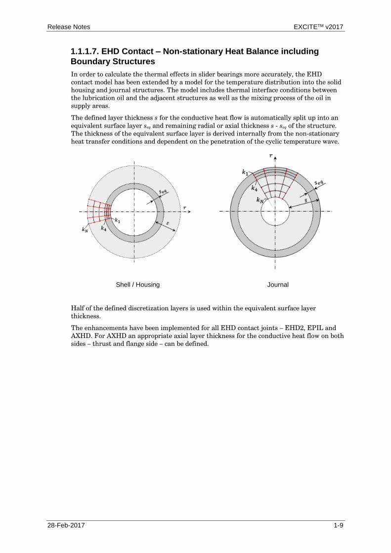
In order to calculate the thermal effects in slider bearings more accurately, the EHD
contact model has been extended by a model for the temperature distribution into the solid
housing and journal structures. The model includes thermal interface conditions between
the lubrication oil and the adjacent structures as well as the mixing process of the oil in
supply areas.
The defined layer thickness s for the conductive heat flow is automatically split up into an
equivalent surface layer seq and remaining radial or axial thickness s - seq of the structure.
The thickness of the equivalent surface layer is derived internally from the non-stationary
heat transfer conditions and dependent on the penetration of the cyclic temperature wave.
Shell / Housing Journal
Half of the defined discretization layers is used within the equivalent surface layer
thickness.
The enhancements have been implemented for all EHD contact joints – EHD2, EPIL and
AXHD. For AXHD an appropriate axial layer thickness for the conductive heat flow on both
sides – thrust and flange side – can be defined.

EXCITETM v2017 Release Notes
1-10 28-Feb-2017
1.1.1.8. New Property Database
The entire Oil Properties Database has been replaced by a newly developed Property
Database, based on the new Simulation Desktop architecture.
The following new features have been implemented:
Support of 3D tables to define temperature, pressure and shear rate dependency.
Extension of Barus models to consider Alpha as a function of pressure and
temperature.
Extension of Cross models to consider the shear rate as a function of temperature.
Mind: as the oil type definition for the model is now stored in the model project
file (.proj), it is important to share both files – <model>.ex and <model>.proj –
for e.g. handover to other users or support.
1.1.1.9. New Handling of Node Sets
In previous versions all node sets available in the Node Sets dialog have been automatically
exported to .exb files either on closing the Node Set dialog or while saving the model. As a
consequence the appropriate .exb files got modified each time and this made many users
uncertain.
Therefore the following changes have been implemented in v2017 regarding node sets
management:
1. Node sets are now stored to an adjacent external file with extension .exb_sets.
2. All node set manipulations like adding, deleting or changing sets will be made to
the adjacent .exb_sets file only.
3. The original generated .exb file will not be modified at all.

Release Notes EXCITETM v2017
28-Feb-2017 1-11
4. Existing node sets in the original .exb file will be copied to adjacent .exb_sets file
during the first operation. The sets in the original .exb file will stay untouched.
5. The automatic export while closing the Node Sets dialog or saving the model is
disabled per default.
6. The user can now either turn on or off the synchronization of all node sets or a
single node set, which means to re-read the sets from .exb_sets while opening the
Node Sets dialog and export them again while closing the dialog or saving the
model.
7. Each node set is now marked with a colored EXCITE logo at the tree node icon.
Dark blue EXCITE logo indicates that node set
will be synchronized automatically
Light blue EXCITE logo indicates that there is a
copy in the .exb_sets file, but synchronization is
turned off
No logo indicates that there is no copy of the node
set in the .exb_sets file
8. EXCITE GUI expects unique node sets across the whole model. Therefore now
checks for name collisions are performed and any findings indicated with a red
exclamation mark. The user has then the possibility to either rename or remove
duplicates.
9. Within the Node Sets dialog the node sets are now grouped in 4 categories
according to their origin:
a. Auto-Search
b. User Defined
c. Modelers – (e.g. generated by Shaft Modeler or Conrod Modeler)
d. FE Model (3D Mesh) – (imported when parsing the 3D mesh input file for
e.g. showing FE model in 3D-View)

EXCITETM v2017 Release Notes
1-12 28-Feb-2017
10. When deleting a set which also exists in the .exb_sets file, the user is asked if the
node set should also be removed from the condensed model file.
11. If the original .exb file gets newly generated and replaced (gets a newer modification
time than its adjacent .exb_sets file), the user is asked what to do:
a. Merge the node sets that are found in a newer .exb file to the existing sets
in .exb_sets (an existing set will be overwritten, new sets will be added).
b. Ignore any new found sets and keep using the existing .exb_sets file.
12. .exb files generated by modelers are always recreated anew before the simulation
runs. Therefore for this category node sets cannot be edited at all.
1.1.1.10. New Utility – Evaluate Web Stiffness
The utility calculates the stiffness values for in-plane, out-of-plane bending and torsion of
each defined crankshaft web based on the structured or condensed stiffness matrix. In
addition the web displacement at journal center due to pre-defined loads will be printed and
plotted. Finally a centrifugal load acting on the mass points of a structured model,
generated with Shaft Modeler, can be applied to each web and the appropriate deformation
will be printed in the report file.

Release Notes EXCITETM v2017
28-Feb-2017 1-13
Results are plotted as bar charts for each web stiffness and are available as an IMPRESS Chart
report. All results as well as information on input data are printed to the report file, too.
Finally a comparison between 2 different crankshaft models is possible.
EXCITETM v2017 Release Notes
1-14 28-Feb-2017
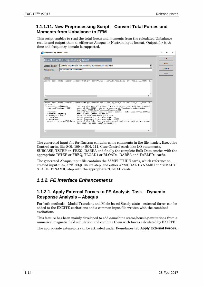
1.1.1.11. New Preprocessing Script – Convert Total Forces and
Moments from Unbalance to FEM
This script enables to read the total forces and moments from the calculated Unbalance
results and output them to either an Abaqus or Nastran input format. Output for both
time and frequency domain is supported.
The generated input file for Nastran contains some comments in the file header, Executive
Control cards, like SOL 109 or SOL 111, Case Control cards like I/O statements,
SUBCASE, TSTEP or FREQ, DAREA and finally the complete Bulk Data entries with the
appropriate TSTEP or FREQ, TLOAD1 or RLOAD1, DAREA and TABLED1 cards.
The generated Abaqus input file contains the *AMPLITUDE cards, which reference to
created input files, a *FREQUENCY step, and either a *MODAL DYNAMIC or *STEADY
STATE DYNAMIC step with the appropriate *CLOAD cards.
1.1.2. FE Interface Enhancements
1.1.2.1. Apply External Forces to FE Analysis Task – Dynamic
Response Analysis – Abaqus
For both methods – Modal Transient and Mode-based Steady-state – external forces can be
added to the EXCITE excitations and a common input file written with the combined
excitations.
This feature has been mainly developed to add e-machine stator/housing excitations from a
numerical magnetic field simulation and combine them with forces calculated by EXCITE.
The appropriate extensions can be activated under Boundaries tab Apply External Forces.
Release Notes EXCITETM v2017
28-Feb-2017 1-15
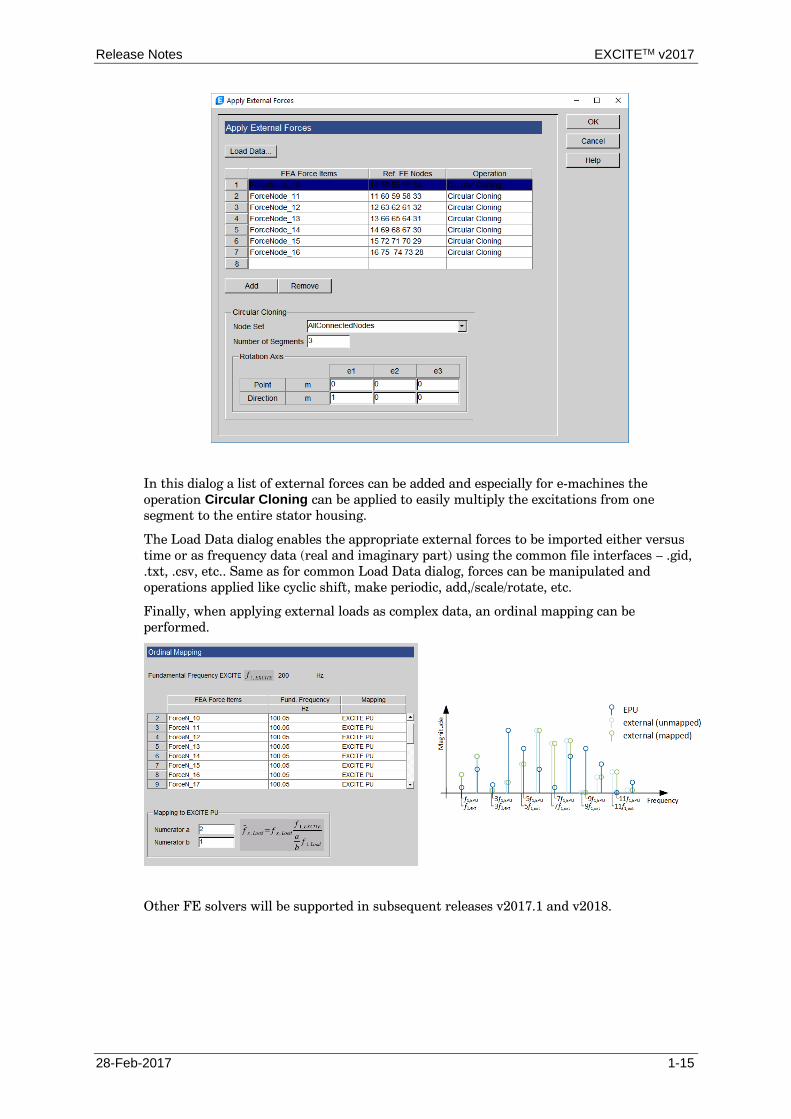
In this dialog a list of external forces can be added and especially for e-machines the
operation Circular Cloning can be applied to easily multiply the excitations from one
segment to the entire stator housing.
The Load Data dialog enables the appropriate external forces to be imported either versus
time or as frequency data (real and imaginary part) using the common file interfaces – .gid,
.txt, .csv, etc.. Same as for common Load Data dialog, forces can be manipulated and
operations applied like cyclic shift, make periodic, add,/scale/rotate, etc.
Finally, when applying external loads as complex data, an ordinal mapping can be
performed.
Other FE solvers will be supported in subsequent releases v2017.1 and v2018.

EXCITETM v2017 Release Notes
1-16 28-Feb-2017
1.1.2.2. Abaqus 2016
Abaqus 2016 is now supported throughout AWS. In particular:
All FE Analysis tasks have been adjusted and EXCITE FEA solvers for both
platforms - Windows/x86-64 and Linux/x86-64 - are available, too.
Utility ‘Convert FE Data’ can convert an Abaqus 2016 .sim file to .exb file.
Utility ‘Modal Data Recovery’ is able to perform a modal stress recovery
reading modal stress data from an Abaqus 2016 .sim database.
Due to inconsistent compiler versions on the Windows/x86-64 platform, IMPRESS 3D will
not be able to access results from an Abaqus 2016 .odb output database.
SIMULIA provides a native abaqus toexcite translator that reads Abaqus data from a
substructure SIM file and writes data to an EXCITE flexible body interface (.exb) file.
The usage is:
abaqus toexcite job=job-name substructure_sim=sim-file
1.1.2.3. Ansys 17.2
Ansys 17.2 is now supported throughout AWS, too. Compared to the previous version 16.0
no significant changes took place.
1.1.2.4. MSC Nastran 2014 and 2016
New DMAP alter files have been introduced (AVL_alter.v2014 and AVL_alter.v2016 as well
as AVL_alter_acms.v2014 and AVL_alter_acms.v2016) to support the latest releases – MSC
Nastran 2014 and 2016 – for condensation jobs. In addition all case based tasks got minor
updates to write proper input files for data recovery for the new MSC Nastran versions.
1.1.2.5. NX Nastran 9 and 10
New DMAP alter files have been introduced (AVL_alter_nxn.v9 and AVL_alter_nxn.v10) to
support the latest releases – NX Nastran 9 and 10 – for condensation jobs. In addition all
case based tasks got minor updates to write proper input files for data recovery for the new
NX Nastran versions.
1.1.2.6. OptiStruct 14.0
Also OptiStruct 14.0 is now fully supported for all FE Analysis tasks and Utilities.
Moreover additional enhancements have been made for:
Condensation:
Possibility to perform a free-interface substructure (Craig-Chang)
Modal transient or frequency response analysis:
Proper support of AMSES or CDH/AMLS
Job submission for running OptiStruct solver via JMS

Release Notes EXCITETM v2017
28-Feb-2017 1-17
Mind: since OptiStruct 14.0.230 also the mesh information is written by the OptiStruct
solver as well as the recovery matrix output to a separate *_RECOVER.exb file.
1.1.2.7. New Support of AVL FIRETM for Thermal Load Analysis
For the FE Analysis task – Thermal Load Analysis – the AVL FIRE solver is supported.
It is now possible to make settings like for the Abaqus solver and generate ASCII files
containing the heat flux as well as heat transfer coefficients (HTC) on a given surface grid
for AVL FIRE.
Both heat flux and heat coefficients can be applied in AVL FIRE as boundary conditions for
a transient thermal analysis.

EXCITETM v2017 Release Notes
1-18 28-Feb-2017
1.1.3. Post-processing Enhancements
1.1.3.1. Piston Report Extensions
The standard Piston Report has the following new results implemented:
Piston noise excitation index (PNEI)
Piston noise response index (PNRI)
Piston1 - Noise Indices
Noise Excitation Index
0.000
0.001
0.002
Excita
tio
n I
nd
ex (
-)
1000 1500 2000 2500 3000 3500 4000 4500
Engine Speed (rpm)
0.0004
0.0011
0.0015
0.0017
0.0015
0.0014
0.0004
0.0011
0.0015
0.0017
0.0015
0.0014
PNEI (-)
Noise Response Index
0
1.1
2.2
Re
sp
on
se
In
de
x (
-)
1000 1500 2000 2500 3000 3500 4000 4500
Engine Speed (rpm)
0.71
0.87
1.32
1.98
1.761.69
0.71
0.87
1.32
1.98
1.761.69
PNRI (-)
Moreover the report generation has been improved considerably and works now for all
types of engines (inline, V) as well as engine orientations.

Release Notes EXCITETM v2017
28-Feb-2017 1-19
1.1.3.2. Tool – Export Case Set Results – Extensions
For exporting excitation data in frequency domain to Nastran Bulk Data format the user
has the possibility to combine quantities like applied external loads and constraint forces as
well as merge excitations on different bodies to one common input file with unique load
identification numbers.
In addition there is now the option to output the frequency results as subcases versus
order, too.
1.1.4. Other Enhancements
Advanced Gear Joint: 'Quick' consideration of circular end relieves for lead corrections
E10-8183
Currently for lead corrections only a linear shaped end relieve (C_beta) can be selected in
the GUI. As a short term solution, a circular-arc shaped end relieve can be taken into
consideration when defining a negative value for the relieve length L_C.
Example:
* C_beta = 10 mym; L_C = 10 mm: Creates a >linear< end relieve of 10 mym cutback
starting at 10 mm distance from the end plane.
* C_beta = 10 mym; L_C = -10 mm: Creates a >circular< end relieve of 10 mym starting
at 10 mm distance from the end plane.
CAM Joint: Variable "contour" stiffness and damping
E20-2622
Variable "contour" stiffness and damping dependent on the position of the contact along the
contour description can be considered now.
CMAT is missing in exb file
E20-2423
When using a condensed model without a corresponding CMAT array in the exb file, the
solver crashed. The problem occurred when the CMAT array was not generated during the
condensation process. This typically happened when forgetting a corresponding command
in the condensation control file. In the case of ABAQUS this is "*FLEXIBLE BODY,
TYPE=EXCITE" in the "* SUBSTRCTURE GENERATION" card. Due to this an internal
NOD6 body was assumed, which finally caused the crash in the kernel. Additional error
checks have been implemented to prevent this kind of model inconsistency.
EHD2 and TEHD Joints: Axial Friction Results
E30-3669
If 'Consider Axial Friction Forces' is requested in 'Bearing Data' properties for an EHD2
joint, the appropriate result is now available at joint results tree entry 'Friction Forces &
Moments'. This shows results for 'Axial Friction Force' related to both connected bodies.
EHD2/ENHD/NONL Joints: Incorrect displacement/orbital path results for uneven amount
of circumferential FE-Nodes

EXCITETM v2017 Release Notes
1-20 28-Feb-2017
E20-2730
In the case of an uneven amount of circumferential FE-Nodes (but more than 1) the orbital
path/displacement results were incorrectly computed. This has been fixed.
EHD2/EPIL/TEHD Joints: Minimum/maximum axial coordinate
E20-2347
Information on minimum and maximum axial coordinate (measured in joint coordinates) is
given in simulation.out (message 1630027).
EHD2 Joint: Mass balance corrected discretization scheme
E20-2686
Alternative discretization schemes for the shear, squeeze and transient term of the
Reynolds equation are available now. These new discretization schemes ensure a better
mass balance in general. Especially if high local clearance height changes are present (e.g.:
geometric boundary condition), not only mass balance is improved significantly but also the
hydrodynamic pressure distribution becomes more realistic.
Element copy and load module keeps the original name and only increases index if
necessary
E10-6812
Copy/paste and loading modules does not revert Body/Joint name to default value anymore.
Element Copy Data for different Radial Bearings
E10-7154
Element Copy Data is now allowed between Radial Bearings (CC, CS and SS) even if a
different type is selected.
EPCL Joint: Drag Loss Calculation
E20-2610
With the feature of drag loss calculation a temperature-dependent, 2-phase evaluation of
drag power/torque of disengaged wet clutches has been done.
EPCL Joint: Friction Force Results
E20-2927
The friction force shares of the clutch can be plotted separately.
FE Interfaces: Importing a thermal deviation from Abaqus .odb
E30-3782
So far the import of a thermal deviation from an Abaqus .odb file only supported the
definition of the surface to be considered by predefined surfaces in CAE. Now the user can
also define the surface via predefined node sets. In addition INSTANCES are supported.
Kinetostatics Solver
E20-2796
The performance of the kinetostatics solver has been enhanced. The obtained results
remain unchanged.
Long initialization time due to initial conditions
E20-2277
Some models took a large number of iterations during the first couple of time steps. This
was caused by initial conditions with approximately zero value. Due to coordinate
transformations etc. (as for instance in the case of V engines) and according round off
errors, signs of in particular velocities may have changed in these cases, which caused the
bad performance. Corresponding enhancements were implemented both in GUI and in the
kernel.
MATLAB Co-simulation: Link to MATLAB
E20-2770

Release Notes EXCITETM v2017
28-Feb-2017 1-21
Automatic starting of MATLAB via EPU for Simulink co-simulations has been restored.
This fix is available for all MATLAB releases greater than R2014b. Older releases still
require a definition of the environment variable FLAME_files. Its value needs to be set to
<installation_path>/IMPRESS/files.
Mode Selection "Power Unit w/o Crank Train"
E10-8132
Up to now users had to specify data from "Cranktrain Globals" even with models which did
not use any engine/powerunit related components. For such models a new mode called
"Power Unit w/o Crank Train" has been introduced. The new mode can be set in Simulation
| Change Mode.
In "Power Unit w/o Crank Train" mode, the "Crank Train Globals" do not need to be
specified. To get correct correlation between time and reference angle, the reference speed
must be set in Model | Define Reference Speed.
Oil Supply Line (OSL) coupling between EHD2 joints
E20-2748
The coupling method between the hydraulic network and the elasto-hydrodynamic joint
was enhanced.
In models where the hydraulic network is connected to a geometrically defined deep groove
the existing strategy failed. With the introduction of an impedance coupling strategy on the
OSL side this problem could be overcome.
With v2017 also the EHD side is treated with an impedance coupling. This now gives
matching flow results between EHD and OSL. No change of user input is necessary.
Primer Models: Initial Conditions
E30-3297
The phasing out variable torque (TPout) has been added to all relevant Primer installation
models. This improves the initial conditions and leads to almost stable conditions after 3
engine cycles.
Results: Body Results Creation
E30-3470
The evaluation of body results has been enhanced by collecting the result requests for one
body and introducing a new function call calc_standard_body_results() in 'results.py'. This
function now opens the binary results data base only once instead of every time for each
node in previous versions. The speed up is in the range of 10 to 30 %.
Results: Full result representation for entire evaluation range although job terminated
earlier
E30-3194
As soon as 'Constant Result Step Size' was enabled in Results - Control, the evaluation tool
also performed an extrapolation of the existing results and generated and plot results for
the entire defined evaluation range.
Now the user will get a warning message, that not all results for the requested interval are
available and only results for calculated steps will be represented in plots.
REVO/NONL Joints: Axial Friction Results
E30-3117
If 'Consider Axial Friction' is requested in 'Friction' properties for joint REVO or NONL,
the appropriate result is now available at the joint results tree entry 'Friction'. This shows
results for '(Total) Axial Friction Force'.
Tools: Import element face sets from Abaqus input file and write to .exb file
E30-3108
Element face sets from Abaqus input file are now imported properly including the face
identifier label and are stored in .exb file in the following notation:

EXCITETM v2017 Release Notes
1-22 28-Feb-2017
Face ID, Face Label
Such imported face sets can now be selected at the data recovery utility.
Utilities - Convert FE Data: Recovery Matrix
E30-3685
Since users request a recovery matrix, the matrix will now be written to a separate file,
called "<bodyname<_RECOVER.exb", as default.
Utilities - Fretting Analysis: Add profile from file at Redefine Node Coordinates
E30-3709
At Utility - Fretting Analysis - Redefine Node Coordinates, it is now possible to import any
e.g. measured profile from a file of the assembled structure and add it to the modified
geometry of the bearing surface nodes. This option is only available for Method - Bore
Definition.
Utilities - Data Recovery: Ansys .tcms error handling
E30-3812
EXCITE Data Recovery on processing .tcms file in the case of error gives more helpful
information now.
Additionally, defining environment variable TCMSDUMP provides more detailed node/dof
information on the following dumped files:
- tcmsNodes.txt: details on tcms data
- condensedNodes.txt: details on EXCITE data
Utilities - excite_exbd: Extended to dump full DOFT and GEOM table from .exb file
E30-3927
The command line utility 'excite_exbd' has been extended to enable the dumping of the full
table of degrees-of-freedom (DOFT) containing all ASET + OSET degrees-of-freedom as
well as geometry table (GEOM) of the entire model from an .exb file. The new command
line arguments are '-doftALL' and '-geomALL'.
Utilities: exciteDload code restructured and new GIDAS reader incorporated
E30-3910
This issue was caused by the channel "IFrc" being removed from GIDAS result files for
condensed bodies, which performed global rotation. The code has been updated to
incorporate a new GIDAS file reader used by exciteRes.
Utilities: Import Temperature Profile from FE Analysis
E30-3846
The largest element size can now be defined at 'Import Temperature Profile from FE
Analysis' to enhance the speed for identifying the non-contact area. This will avoid an
expensive computation of the same value by the program internally.
Utilities: Output total forces and moments from Unbalance to Nastran BDF / Abaqus INP
E30-3722
A new pre-processing script "Convert Total Forces And Moments from Unbalance to FEM"
is available which enables the creation of input files for Nastran and Abaqus solvers based
on the Unbalance data calculated by the "Unbalance" pre-processing script.

Release Notes EXCITETM v2017
28-Feb-2017 1-23
1.2. EXCITE Designer
1.2.1. New Features
1.2.1.1. MB and Web Load: Extended Modeling of Main Bearings
and Additional Results
There is a new section in the Simulation Control dialog (marked on the image below),
which allows to prescribe the distribution of radial stiffness and damping in the main
bearings over their width. Note: the previous versions supported only the first option – End
Nodes Only.

EXCITETM v2017 Release Notes
1-24 28-Feb-2017
Another extension of the modeling capabilities is achieved by introducing flexible supports
for main bearing shells (shown on the scheme above). If Flexibly Supported Rigid Bearing
Shell is selected (marked on the image above), a new node and dialog window Bearing
Shell containing the relevant parameters will be activated for all main bearing joints (see
the image below).
In addition to the main bearing loads and web loads, linear and angular displacement and
velocity results for any node of the crankshaft can be calculated now, both in absolute and
relative (rotating) coordinate systems (see the mark below).
The group of such nodes can be chosen using the new section in the Simulation Control
window.
Besides that, a new type of result has been added, which evaluates the linear and angular
misalignment of the journal and shell in each of the main bearings (see the mark above).

Release Notes EXCITETM v2017
28-Feb-2017 1-25
1.2.1.2. Torsion: Potential Energy Distribution in Torsional Modes
Together with the kinetic energy at nodes of the torsional vibration system, it is also
possible to see the potential energy of elastic elements for each mode, in the form of a bar
diagram.
1.2.2. Enhancements
Bearing Calculation: Butenschoen is set as the default calculation model
E10-8130
The default calculation model for the EXCITE Designer Bearing calculation is now set to
"Butenschoen".
Input-output correspondence for V-engines with bank-wise definition of cylinder IDs
E10-6576
For V-engines with bank-wise definition of cylinder IDs, the GUI re-numbered the
cylinders internally. Thus the cylinder numbering in the results did not correspond to the
defined cylinder IDs. The internal re-numbering has been removed.
Mount Layout Tool: Increase the max. number of mounts
E34-1271
The maximum number of mounts is set to 50. The mounts are grouped by their
characteristics within property charts now, instead of showing a curve for every single
mount.
Standard Reports: Create reports has to show current progress
E34-1182
Refined progress tracking for EXCITE Designer reports has been implemented.

EXCITETM v2017 Release Notes
1-26 28-Feb-2017
1.3. EXCITE Piston&Rings
1.3.1. Reworking the 3D Ring Dynamics Module
In the previously released version, the 3D ring Module showed instability. Therefore, the
source code was analyzed and the following modifications have been done:
The ring dynamics modeling approach was enhanced (details are given in the
next section).
A new Reynolds solver which is used to model the ring running face lubrication
was introduced. The solution technique ensures mass conservation within the
hydrodynamic contact area based on JFO boundary conditions. A fill ratio θ is
introduced to the Reynolds equation. Reynolds equation is solved for the fill
ratio, if the hydrodynamic pressure in the cell fails under the cavitation
pressure.
1.3.2. Enhancement of Ring Dynamics Modeling Approach
Starting from v2017 two approaches to calculate the gap between the ring surface and
piston flank as well as between the ring running face and the liner are facilitated. Namely,
the method used in the previous versions, which is called “Ring 2D Classic” and a new
method which is called “Ring 2D Enhanced”.
The user can select between these 2 methods as well as carrying out 3D ring dynamic
analysis by enabling the approach required as shown in the following figure:
The 2D classic ring implementation uses the following steps to calculate the ring-piston
flank and ring running face liner clearance as a function of the original coordinates and
twist and piston tilt angles:
Grid Points on the Piston Groove:
The new position of the grid points on the piston groove are updated by
rotating their coordinates around the ring center by the sum of tilt and twist
angles.
Grid Points on the Ring Flank:
The change of the position of the grid points on the ring flank are calculated by
rotating their coordinates by an angle equal to the sum of the piston tilt and
ring twist around the center of the ring cross section.
Grid Points on the Ring Running Face:
The new position is calculated by multiplying the axial coordinate by the
tangent of the sum of piston tilt and ring twist angles.
Release Notes EXCITETM v2017
28-Feb-2017 1-27
The 2D Enhanced approach calculates the gap between the ring and piston flanks from one
side and between the ring running face and the liner wall from the other side as follows:
Grid Point on the Piston Groove:
The new position of the grid points on the piston groove are updated by
rotating their coordinates around the piston pin by the tilt angle.
Grid Points on the Ring Flank:
The position of the grid points on the ring flank are calculated in two steps. In
the first step, the coordinates are rotated around the piston pin by the tilt angle
and in the next step they are rotated around the center of the ring cross section
by the twist angle.
Grid Points on the Ring Running Face:
The new position is calculated by rotating the coordinates of the running face
grid points by the twist angle around the center of the ring cross section.
The 3D ring dynamics approach is based on the enhanced method.
1.3.3. Enhancement of GUI Input Data
The redundancy in the force balance iteration (accuracy at the GUI) input data is removed.
The number of time steps per crank angle and oil film force balance are required for 2D
ring modeling. For 3D ring modeling, the global iteration requires the number of time steps
per crank angle, a tolerance value for 3D ring dynamics solver and the maximum number
of iterations per time step.
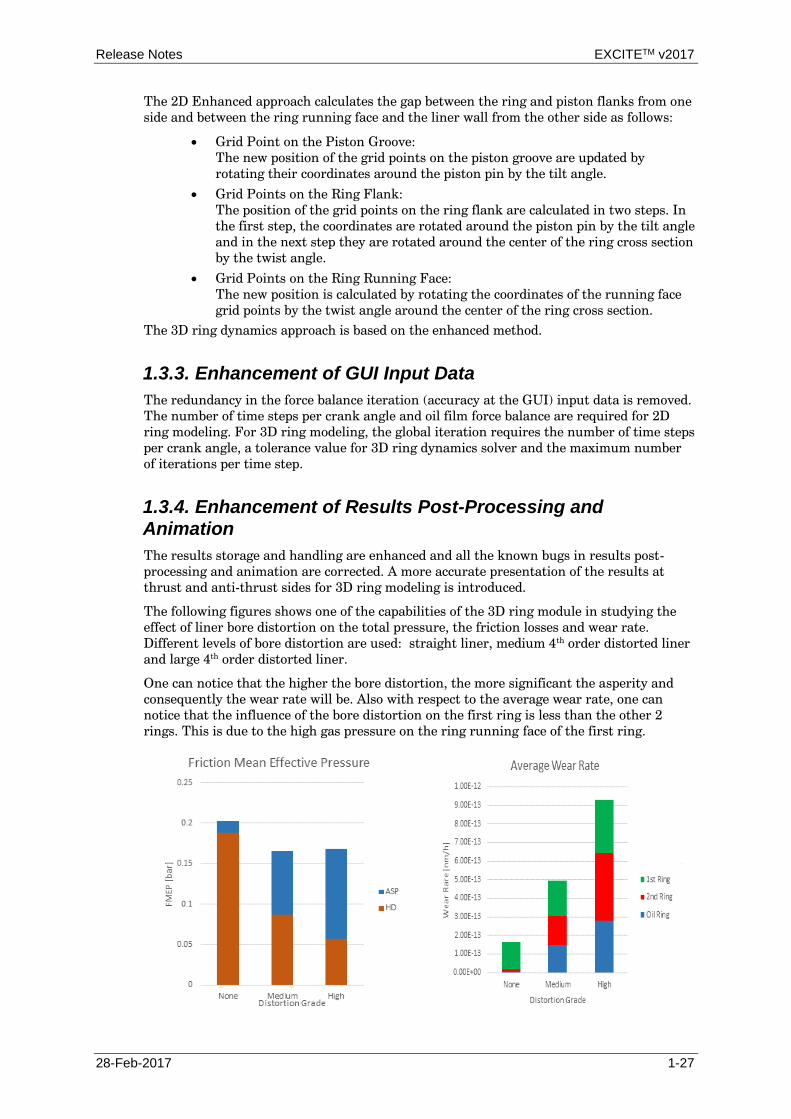
1.3.4. Enhancement of Results Post-Processing and Animation
The results storage and handling are enhanced and all the known bugs in results post-
processing and animation are corrected. A more accurate presentation of the results at
thrust and anti-thrust sides for 3D ring modeling is introduced.
The following figures shows one of the capabilities of the 3D ring module in studying the
effect of liner bore distortion on the total pressure, the friction losses and wear rate.
Different levels of bore distortion are used: straight liner, medium 4th
order distorted liner
and large 4th
order distorted liner.
One can notice that the higher the bore distortion, the more significant the asperity and
consequently the wear rate will be. Also with respect to the average wear rate, one can
notice that the influence of the bore distortion on the first ring is less than the other 2
rings. This is due to the high gas pressure on the ring running face of the first ring.

EXCITETM v2017 Release Notes
1-28 28-Feb-2017
Total pressure on the ring running face
Straight liner (40 microns
deviation)
Max Deviation = 45 microns
Min Deviation = 35 microns
Max Deviation = 70 microns
Min Deviation = 10 microns
1.3.5. Storing Data for Thermal Load Calculations
Thermal Load Analysis (TLA) is used to evaluate and create contact heat transfer
boundary conditions. EXCITE Piston & Rings enables a contact analysis with the
evaluation of thermal load due to friction and non-stationary heat transfer coefficient
averaged over engine cycle.
Template files FavoritesDefinition_NNrings.fav are created to import additional
input data for thermal load analysis. Template file data (1.3) should be imported into
Model | Favorites Designer (1.1, 1.2, 1.4).
The provided input data can be checked or adjusted under Model | Favorites (2.1, 2.2). In
Simulation | Preprocessing Script | Thermal Load Analysis (3.1, 3.2) the TLA evaluation
will be started.

Release Notes EXCITETM v2017
28-Feb-2017 1-29
The following outputs will be created: two Abaqus input files as well as an output file.
Abaqus input files contain thermal BC’s for stationary structural thermal analysis of piston
group and cylinder block. Another output file data can be used to create thermal BC’s for
any other FE solver.
1.3.1. Enhancements
General Interpolation Error
E10-8190
The program stops showing a "General interpolation error" if cylinder pressure or
thermodynamic data tables include multiple table entries for the same angle. To avoid such
problems additional data checks have been introduced to make sure that data within the
Crank Angle column is strictly ascending.
License Check for Spring Clip
E35-1057
The license check for ring clips is removed and it can be accessed by all customers.
Number of Interpolation Points on the Ring Running Face
E35-1056
The number of interpolation points on the ring running face was limited to 50. The limit is
removed and it is dynamically allocated. The only limit is that this number should be more
than the number of points which define the running face profile.
Running Surface: Mass Conserving Hydrodynamic Solver
E35-890
A mass conserving hydrodynamic solver has been implemented for the running face
contact. This algorithm is used if 2D-advanced or 3D ring is chosen.
Wrong Sign of the Ring Flank Radial Friction Force
E35-1020
The direction of the friction force was in the positive direction of the ring-flank relative
velocity. This sign is corrected.

EXCITETM v2017 Release Notes
1-30 28-Feb-2017
1.4. EXCITE Timing Drive
1.4.1. Enhancements
Case Set Reports
E30-4013
In previous versions 'standard_reports_caseset.py' was written to every folder and executed
for each case. Now there is one accumulated script written to the Case Set folder and
therefore modifications have been made to accommodate this (different) workflow.
Output/Evaluation of Absolute Spring Coil Positions
E10-8017
A new user defined result script called "ESPR absolute positions" is available. It evaluates
the absolute spring (coil) positions for spring macro components. Zero position is equivalent
to the bottom end of the spring.
User Defined Result Function "Contact Point Global"
E10-7801
The script for the determination of the global contact point in contour contacts was
extended to additionally extract the contact point expressed in the local coordinate system
of the 2 bodies.
User Defined Result Shear Stress: Update of Stress Concentration Factor
E10-8101
The stress concentration factor in the shear stress calculation of springs is now calculated
according to the formula by Bergstraesser. This results in 1-2% smaller stress
concentration factors compared to the previously used method and correspondingly the
stress levels are reduced by 1-2% compared to results achieved with previous versions.

Release Notes EXCITETM v2017
28-Feb-2017 1-31
1.5. EXCITE Acoustics
1.5.1. New Features
1.5.1.1. Customized Color Settings
For newly introduced selections or panels the user can now change the colors (double click
on colored square). Notice that for Multi Local Velocity and Fluid-Fluid Coupling
Selections the colors are fixed with red and blue.

EXCITETM v2017 Release Notes
1-32 28-Feb-2017
1.5.1.2. DB Weighting for 3D Sound Pressure Level Results and
Audio Files
A new pull down menu has been introduced to select dB sound pressure weighting for all
3D results and Audio wave files. The pull down menu provides No, A, B and C weighting
according to DIN-IEC 651.
1.5.1.3. Show Acoustic Surface ID’s
If Selection Control is selected in the Elements Tree it is now possible to show the surface
id’s of an acoustic mesh if the corresponding check box (Surface Labels) is activated.
In this case (e.g. *_l.log) the log output can be analyzed more easily.

Release Notes EXCITETM v2017
28-Feb-2017 1-33
1.5.1.4. Automatic Mesh File Export
Up to now the acoustic meshes generated during the pre-processing step have to be
exported manually (Export button in the ribbon).
With v2017 an additional automatic “naming export” has been introduced (Apply button).
The file naming conventions and positions are shown in the following example figure.
Merged Mesh:
modeling\geometry\meshes\EXCITE
Acoustics\file_name\I4demo\2017_02_30_1
5_51_12__acoustic_mesh.flm
Field Point Mesh:
modeling\geometry\meshes\EXCITE
Acoustics\file_name\I4demo\2017_02_30_1
5_59_04__field_point_mesh.flm
modeling\geometry\meshes\<client>\<project_name>\<model_name>\<date>__<mesh_type>
1.5.1.5. Mapped Velocity Visualization
To visualize the mapped velocity over frequency a new type of Simulation Task (Multi
Local Velocity (MLV)) has been introduced.
After a successfully finished simulation run, the mapped velocities can be imported to the
3D Viewer of IMPRESS M by selecting 3D | MLV Mapping and a specific Quantity (e.g.
Normal Velocity).

EXCITETM v2017 Release Notes
1-34 28-Feb-2017
1.5.1.6. Sound Power Level (ISO 3745)
With v2017 the output quantity Sound Power Level given by ISO 3745:2012 is supported.
For the calculation of the sound power level the measurement standard (sphere with 40
microphones) for free field is used.
If panels are defined, the contribution of each panel to the Sound Power Level is now also
available as dB(A), dB(B) and dB(C) weighted quantity.

Release Notes EXCITETM v2017
28-Feb-2017 1-35
For the post-processing with IMPRESS M a corresponding new folder including all
quantities is provided.

EXCITETM v2017 Release Notes
1-36 28-Feb-2017
1.5.1.7. Bar Chart for Octave and 3rd Octave Bands
Compared to the previous releases, v2017 provides a new type of chart called bar chart
which can be used instead of the line chart template .
Notice the standard report template (E_AC_Report_001) uses the new bar chart instead of
the old line chart templates.
1.5.2. Enhancements
Audio Channel
SE37-314
The possibility of selecting Audio Channel (Mono/Stereo) has been implemented in v2017.
Audio Output Mono/Stereo
SE37-313
Audio output selection for Mono and Stereo has been implemented in v2017.
Effective Value for dB
SE37-254
The possibility of selecting the Effective Value for dB (rms/peak) has been implemented in v2017.
Microphone Pressure Output to Standard Output
SE37-393
With v2017 the Sound Pressure Level for the six standard microphones is written to the
standard output additionally.
MLV Geometry / Result File Definition
SE37-304
A new strategy for the definition of a Multi Local Velocity file pair is provided with the
present release. For those file types which contain geometry and results (*.odb, *.rst,
*,op2), an additional geometry file can be defined which overrules the geometry data of
*.odb, *.rst, *,op2.

Release Notes EXCITETM v2017
28-Feb-2017 1-37
Panel Results as Phase
SE37-396
For the Panel Contribution Output a new quantity (Phase with unit radiant) has been
implemented in EXCITE Acoustics. The new panel quantity is automatically generated if
the acoustic model consists of at least one panel.
Pressure Peak versus RMS
SE37-194
With v2017 the user can decide if the pressure dependent results are based on peak or rms
values.
1.6. EXCITE Pre-processing Tools
1.6.1. Shaft Modeler: New Features
1.6.1.1. Gyroscopic Modal Analysis: Resonances
Two plots have been added to the Critical Speeds report, containing resonances, both in
absolute and relative (rotating) coordinate systems.
1.6.1.2. Modal Analysis of Flexibly Supported Shaft: New Options
There are new options now in the definition of main bearing radial stiffness for modal
analysis of flexibly supported shaft, with or without taking the gyroscopic effects into
account.
The new options are:
Radial stiffness definition separately for each main bearing
Speed dependent radial stiffness of main bearings

EXCITETM v2017 Release Notes
1-38 28-Feb-2017
1.6.1.3. Enhancement
Simple Floating and Guided Valve Bridge Models
E33-782
Structured models of simple floating and guided valve bridge are generated.
1.6.2. Autoshaft
FE Interfaces: FE Stress Mesh in ANSYS Format
E33-725
AutoSHAFT also exports FE stress meshes in ANSYS format now.
STROKE is replaced by CRANK RADIUS
E33-763
In .rpt and .rp2 files, STROKE is replaced by CRANK RADIUS (where applicable)
Surface Repair for AutoSHAFT
E33-673
The Surface Repair content is included in the Shaft Modeler Users Guide as Appendix G.