version 3.0 user’s guide - gilson trilution lc v3_0 user's gui… · table of contents...
TRANSCRIPT

Version 3.0 User’s Guide
Gilson, Inc. | PO Box 620027 | Middleton, WI 53562-0027, USATel: 608-836-1551 or 800-445-7661 | Fax: 608-831-4451
Gilson S.A.S. | 19, avenue des Entrepreneurs | BP 145 | F-95400 Villiers-le-bel, FRANCE
www.gilson.com | [email protected] | [email protected] | [email protected]
LT375037-01 ©2012 Gilson, Inc. | All rights reserved.


Table of Contents
Gilson TRILUTION® LC Software v3.0 User’s Guide Table of Contents-1
1 TRILUTION® LC Software OverviewUnpacking . . . . . . . . . . . . . . . . . . . . . . . . . . . . . . . . . . . . . . . . . . . . . . . . . . . . . 1-2
Customer Education . . . . . . . . . . . . . . . . . . . . . . . . . . . . . . . . . . . . . . . . . . . 1-3Instrument TechTips and Web Courses . . . . . . . . . . . . . . . . . . .1-3Local Workshops . . . . . . . . . . . . . . . . . . . . . . . . . . . . . . . . . . . . . . . . .1-3Classroom Courses . . . . . . . . . . . . . . . . . . . . . . . . . . . . . . . . . . . . . . .1-3One Hour Web Seminars . . . . . . . . . . . . . . . . . . . . . . . . . . . . . . . . .1-4CD Education . . . . . . . . . . . . . . . . . . . . . . . . . . . . . . . . . . . . . . . . . . . .1-4Registration . . . . . . . . . . . . . . . . . . . . . . . . . . . . . . . . . . . . . . . . . . . . .1-4Course Fees . . . . . . . . . . . . . . . . . . . . . . . . . . . . . . . . . . . . . . . . . . . . . .1-4Cancellation, No Show Substitution . . . . . . . . . . . . . . . . . . . . . .1-4
Customer Service . . . . . . . . . . . . . . . . . . . . . . . . . . . . . . . . . . . . . . . . . . . . . . 1-5Before Calling Us . . . . . . . . . . . . . . . . . . . . . . . . . . . . . . . . . . . . . . . . .1-5
Start TRILUTION LC . . . . . . . . . . . . . . . . . . . . . . . . . . . . . . . . . . . . . . . . . . . . 1-6Log In . . . . . . . . . . . . . . . . . . . . . . . . . . . . . . . . . . . . . . . . . . . . . . . . . . .1-6
Help . . . . . . . . . . . . . . . . . . . . . . . . . . . . . . . . . . . . . . . . . . . . . . . . . . . . . . . . . . . 1-7
TRILUTION LC Menus . . . . . . . . . . . . . . . . . . . . . . . . . . . . . . . . . . . . . . . . . . 1-8Liquid Chromatography . . . . . . . . . . . . . . . . . . . . . . . . . . . . . . . . .1-8Administrative Tools . . . . . . . . . . . . . . . . . . . . . . . . . . . . . . . . . . . 1-14Log Out . . . . . . . . . . . . . . . . . . . . . . . . . . . . . . . . . . . . . . . . . . . . . . . . 1-21Lock . . . . . . . . . . . . . . . . . . . . . . . . . . . . . . . . . . . . . . . . . . . . . . . . . . . 1-21Back . . . . . . . . . . . . . . . . . . . . . . . . . . . . . . . . . . . . . . . . . . . . . . . . . . . 1-21
GEARS . . . . . . . . . . . . . . . . . . . . . . . . . . . . . . . . . . . . . . . . . . . . . . . . . . . . . . . .1-22
TRILUTION LC Backup Utility . . . . . . . . . . . . . . . . . . . . . . . . . . . . 1-22
Close TRILUTION LC . . . . . . . . . . . . . . . . . . . . . . . . . . . . . . . . . . . . 1-22
2 Project LibraryProject Library Window . . . . . . . . . . . . . . . . . . . . . . . . . . . . . . . . . . . . . . . .2-2
Applications Palette . . . . . . . . . . . . . . . . . . . . . . . . . . . . . . . . . . . . . 2-2Methods Palette . . . . . . . . . . . . . . . . . . . . . . . . . . . . . . . . . . . . . . . . . 2-3Filter . . . . . . . . . . . . . . . . . . . . . . . . . . . . . . . . . . . . . . . . . . . . . . . . . . . . 2-3Workspace . . . . . . . . . . . . . . . . . . . . . . . . . . . . . . . . . . . . . . . . . . . . . . 2-4Action Buttons . . . . . . . . . . . . . . . . . . . . . . . . . . . . . . . . . . . . . . . . 2-7Info Window . . . . . . . . . . . . . . . . . . . . . . . . . . . . . . . . . . . . . . . . . . . . 2-7
Project . . . . . . . . . . . . . . . . . . . . . . . . . . . . . . . . . . . . . . . . . . . . . . . . . . . . . . . . .2-8How to Create a Project . . . . . . . . . . . . . . . . . . . . . . . . . . . . . . . . . 2-8How to Share a Project . . . . . . . . . . . . . . . . . . . . . . . . . . . . . . 2-10Modify a Project . . . . . . . . . . . . . . . . . . . . . . . . . . . . . . . . . . . . . . . .2-10How to Export Projects . . . . . . . . . . . . . . . . . . . . . . . . . . . . . . . . .2-11How to Import Projects . . . . . . . . . . . . . . . . . . . . . . . . . . . . . . . . .2-12Delete a Project . . . . . . . . . . . . . . . . . . . . . . . . . . . . . . . . . . . . . . . .2-13
Application . . . . . . . . . . . . . . . . . . . . . . . . . . . . . . . . . . . . . . . . . . . . . . . . . . 2-14How to Create an Application . . . . . . . . . . . . . . . . . . . . . . . . . .2-14Modify an Application . . . . . . . . . . . . . . . . . . . . . . . . . . . . . . . . . .2-14How to Export Applications . . . . . . . . . . . . . . . . . . . . . . . . . . . .2-15How to Import Applications . . . . . . . . . . . . . . . . . . . . . . . . . . . .2-16Delete an Application . . . . . . . . . . . . . . . . . . . . . . . . . . . . . . . . . .2-17
View Results . . . . . . . . . . . . . . . . . . . . . . . . . . . . . . . . . . . . . . . . . . . . 2-17

Table of Contents-2 Gilson TRILUTION® LC Software v3.0 User’s Guide
3 Method BuilderMethod Builder Window . . . . . . . . . . . . . . . . . . . . . . . . . . . . . . . . . . . . . . 3-2
Configuration Tab . . . . . . . . . . . . . . . . . . . . . . . . . . . . . . . . . . . . . . .3-2Bed Layout Tab . . . . . . . . . . . . . . . . . . . . . . . . . . . . . . . . . . . . . . . . . .3-2Control Tab . . . . . . . . . . . . . . . . . . . . . . . . . . . . . . . . . . . . . . . . . . . . . .3-2Analysis Tab . . . . . . . . . . . . . . . . . . . . . . . . . . . . . . . . . . . . . . . . . . . . .3-2Configured Instruments Panel . . . . . . . . . . . . . . . . . . . . . . . . . . .3-3Action Buttons. . . . . . . . . . . . . . . . . . . . . . . . . . . . . . . . . . . . . . . . 3-5Info Window . . . . . . . . . . . . . . . . . . . . . . . . . . . . . . . . . . . . . . . . . . . . .3-5
How to Create a Method . . . . . . . . . . . . . . . . . . . . . . . . . . . . . . . . . . . . . . 3-6
How to Save a Method . . . . . . . . . . . . . . . . . . . . . . . . . . . . . . . . . . . . . . . . 3-7Basic Save . . . . . . . . . . . . . . . . . . . . . . . . . . . . . . . . . . . . . . . . . . . . . . .3-7Save Method Using Shared Components <OK to Update> . . . . . . . . . . . . . . . . . . . . . . . . . . . . . . . . . . . . . . . . .3-8Save Method Using Shared Components<Cannot Update> . . . . . . . . . . . . . . . . . . . . . . . . . . . . . . . . . . . . . . .3-9
View a Method . . . . . . . . . . . . . . . . . . . . . . . . . . . . . . . . . . . . . . . . . . . . . . .3-10
How to Export Methods . . . . . . . . . . . . . . . . . . . . . . . . . . . . . . . . . . . . . .3-11
How to Import Methods . . . . . . . . . . . . . . . . . . . . . . . . . . . . . . . . . . . . . .3-12System Conflicts . . . . . . . . . . . . . . . . . . . . . . . . . . . . . . . . . . . . . . . 3-12
Delete Methods . . . . . . . . . . . . . . . . . . . . . . . . . . . . . . . . . . . . . . . . . . . . . .3-13
Close the Method Builder . . . . . . . . . . . . . . . . . . . . . . . . . . . . . . . . . . . .3-14
4 Method Builder - ConfigurationConfiguration Tab Window . . . . . . . . . . . . . . . . . . . . . . . . . . . . . . . . . . . .4-2
Instrument Types . . . . . . . . . . . . . . . . . . . . . . . . . . . . . . . . . . . . . . . . 4-2Workspace . . . . . . . . . . . . . . . . . . . . . . . . . . . . . . . . . . . . . . . . . . . . . . 4-2Available Instruments . . . . . . . . . . . . . . . . . . . . . . . . . . . . . . . . . . . 4-3Properties . . . . . . . . . . . . . . . . . . . . . . . . . . . . . . . . . . . . . . . . . . . . . . . 4-3
How to Create a Configuration . . . . . . . . . . . . . . . . . . . . . . . . . . . . . . . .4-4
Modify a Configuration . . . . . . . . . . . . . . . . . . . . . . . . . . . . . . . . . . . . . . 4-26Remove an Instrument from a Configuration . . . . . . . . . . .4-26
5 Method Builder - Bed LayoutBed Layout Tab Window . . . . . . . . . . . . . . . . . . . . . . . . . . . . . . . . . . . . . . .5-2
Zone Management . . . . . . . . . . . . . . . . . . . . . . . . . . . . . . . . . . . . . . 5-2Zone Numbering Pattern . . . . . . . . . . . . . . . . . . . . . . . . . . . . . . . . 5-2Workspace . . . . . . . . . . . . . . . . . . . . . . . . . . . . . . . . . . . . . . . . . . . . . . 5-3Color Management . . . . . . . . . . . . . . . . . . . . . . . . . . . . . . . . . . . . . . 5-3
How to Create a Bed Layout . . . . . . . . . . . . . . . . . . . . . . . . . . . . . . . . . . .5-4Select a Template . . . . . . . . . . . . . . . . . . . . . . . . . . . . . . . . . . . . . . . 5-4Define a Zone . . . . . . . . . . . . . . . . . . . . . . . . . . . . . . . . . . . . . . . . . . . 5-4Add a Rack/Rinse Station/Injection Port . . . . . . . . . . . . . . . . . . 5-5Select a Zone Numbering Pattern . . . . . . . . . . . . . . . . . . . . . . . 5-5Number Wells in Zone . . . . . . . . . . . . . . . . . . . . . . . . . . . . . . . . . . . 5-5
How to Modify a Bed Layout . . . . . . . . . . . . . . . . . . . . . . . . . . . . . . . . . . .5-6

Gilson TRILUTION® LC Software v3.0 User’s Guide Table of Contents-3
6 Method Builder - ControlControl Tab Window . . . . . . . . . . . . . . . . . . . . . . . . . . . . . . . . . . . . . . . . . . 6-2
Tasks Palette . . . . . . . . . . . . . . . . . . . . . . . . . . . . . . . . . . . . . . . . . . . . .6-2Workspace Tab . . . . . . . . . . . . . . . . . . . . . . . . . . . . . . . . . . . . . . . . . .6-3Error Handling Tab . . . . . . . . . . . . . . . . . . . . . . . . . . . . . . . . . . . . . . .6-6
Schedule Timed Tasks . . . . . . . . . . . . . . . . . . . . . . . . . . . . . . . . . . . . . . . .6-12Modify Task Time and/or Properties . . . . . . . . . . . . . . . . . . . . 6-12Modify Task . . . . . . . . . . . . . . . . . . . . . . . . . . . . . . . . . . . . . . . . . . . . 6-12Delete Task from Control . . . . . . . . . . . . . . . . . . . . . . . . . . . . . . 6-12
How to Create Gradient or Isocratic Conditions . . . . . . . . . . . . . .6-13Add a Point to the Mobile Phase Template . . . . . . . . . . . . . 6-13Modify Points on the Mobile Phase Template . . . . . . . . . 6-14Delete Points on the Mobile Phase Template. . . . . . . . . . 6-16
Fraction Collection Simulation . . . . . . . . . . . . . . . . . . . . . . . . . . . . . . .6-17How to Simulate Fraction Collection by Slope or Level . 6-17How to Modify the Appearance of Overlaid Results . . . . . 6-18
7 Method Builder - AnalysisAnalysis Tab Window . . . . . . . . . . . . . . . . . . . . . . . . . . . . . . . . . . . . . . . . . . 7-2
Peak Integration Tab . . . . . . . . . . . . . . . . . . . . . . . . . . . . . . . . . . . . .7-2Report Tab. . . . . . . . . . . . . . . . . . . . . . . . . . . . . . . . . . . . . . . . . . . 7-14Error Handling Tab. . . . . . . . . . . . . . . . . . . . . . . . . . . . . . . . . . . 7-29
How to Create an Analysis . . . . . . . . . . . . . . . . . . . . . . . . . . . . . . . . . . . .7-31Remove an Analysis . . . . . . . . . . . . . . . . . . . . . . . . . . . . . . . . . . . . 7-31
Integration Tasks . . . . . . . . . . . . . . . . . . . . . . . . . . . . . . . . . . . . . . . . . . . . .7-32Analysis Settings . . . . . . . . . . . . . . . . . . . . . . . . . . . . . . . . . . . . . . . 7-34Baseline . . . . . . . . . . . . . . . . . . . . . . . . . . . . . . . . . . . . . . . . . . . . . . . 7-34Inhibit/Enable Integration . . . . . . . . . . . . . . . . . . . . . . . . . . . . . 7-37Negative Peak . . . . . . . . . . . . . . . . . . . . . . . . . . . . . . . . . . . . . . . . . 7-37Start/Stop Integration by Fraction Collection . . . . . . . . . . . 7-38
How to Define Retention Time Windows . . . . . . . . . . . . . . . . . . . . .7-39Resolve Overlapping Retention Time Windows . . . . . . . . 7-40
How to Use the Peak Table During Data Analysis . . . . . . . . . . . . 7-41Reasons for Missing Peaks . . . . . . . . . . . . . . . . . . . . . . . . . . . . . .7-41Locate Reference Peaks . . . . . . . . . . . . . . . . . . . . . . . . . . . . . . . .7-41Locate Non-Reference Peaks . . . . . . . . . . . . . . . . . . . . . . . . . . .7-42Update Peak Retention Times . . . . . . . . . . . . . . . . . . . . . . . . . .7-42
How to Create an Analysis Report . . . . . . . . . . . . . . . . . . . . . . . . . . . 7-43Annotation Contents . . . . . . . . . . . . . . . . . . . . . . . . . . . . . . . . . . .7-43Graph Settings . . . . . . . . . . . . . . . . . . . . . . . . . . . . . . . . . . . . . . . . .7-44Sample Table . . . . . . . . . . . . . . . . . . . . . . . . . . . . . . . . . . . . . . . . . . .7-44Spectrum Settings . . . . . . . . . . . . . . . . . . . . . . . . . . . . . . . . . . . . . .7-45Run Variables . . . . . . . . . . . . . . . . . . . . . . . . . . . . . . . . . . . . . . . . . . .7-45Grouped Peaks . . . . . . . . . . . . . . . . . . . . . . . . . . . . . . . . . . . . . . . . .7-45Auto Action . . . . . . . . . . . . . . . . . . . . . . . . . . . . . . . . . . . . . . . . . . . .7-45
Schedule Timed Integration Tasks . . . . . . . . . . . . . . . . . . . . . . . . . . . 7-46Add Integration Task to Analysis . . . . . . . . . . . . . . . . . . . . . . . .7-46Modify Integration Task . . . . . . . . . . . . . . . . . . . . . . . . . . . . . . . .7-46Delete Integration Task from Analysis . . . . . . . . . . . . . . . . . .7-46

Table of Contents-4 Gilson TRILUTION® LC Software v3.0 User’s Guide
8 Application RunApplication Run Window . . . . . . . . . . . . . . . . . . . . . . . . . . . . . . . . . . . . . . 8-2
Title Bar . . . . . . . . . . . . . . . . . . . . . . . . . . . . . . . . . . . . . . . . . . . . . . . . . .8-2Application Run Toolbar . . . . . . . . . . . . . . . . . . . . . . . . . . . . . . . . .8-3Status Box . . . . . . . . . . . . . . . . . . . . . . . . . . . . . . . . . . . . . . . . . . . . . . .8-3Run Time . . . . . . . . . . . . . . . . . . . . . . . . . . . . . . . . . . . . . . . . . . . . . . . .8-3Pause Time . . . . . . . . . . . . . . . . . . . . . . . . . . . . . . . . . . . . . . . . . . . 8-4Sample List Toolbar . . . . . . . . . . . . . . . . . . . . . . . . . . . . . . . . . . . . . .8-4Sample List Name . . . . . . . . . . . . . . . . . . . . . . . . . . . . . . . . . . . . . . . .8-6Sample List Columns . . . . . . . . . . . . . . . . . . . . . . . . . . . . . . . . . . . . .8-6Run Name . . . . . . . . . . . . . . . . . . . . . . . . . . . . . . . . . . . . . . . . . . . . . . .8-9Maintenance Alarm Reminder . . . . . . . . . . . . . . . . . . . . . . . . 8-10Method Configuration Toolbar . . . . . . . . . . . . . . . . . . . . . . . . . 8-10Chromatogram Tab . . . . . . . . . . . . . . . . . . . . . . . . . . . . . . . . . . . . 8-10Bed Layout Tab . . . . . . . . . . . . . . . . . . . . . . . . . . . . . . . . . . . . . . . . 8-11Mass Spec Spectra for Fractions Tab . . . . . . . . . . . . . . . . . . . . 8-11Action Buttons . . . . . . . . . . . . . . . . . . . . . . . . . . . . . . . . . . . . . . . . . 8-12Info Window . . . . . . . . . . . . . . . . . . . . . . . . . . . . . . . . . . . . . . . . . . . 8-12
How to Create a Sample List . . . . . . . . . . . . . . . . . . . . . . . . . . . . . . . . . .8-13How to Create a Sample List for Fraction Collection . . . . 8-13How to Create a Sample List to Re-inject Collected Fractions. . . . . . . . . . . . . . . . . . . . . . . 8-15Set Initial Volumes . . . . . . . . . . . . . . . . . . . . . . . . . . . . . . . . . . . . . 8-16
How to Export a Sample List . . . . . . . . . . . . . . . . . . . . . . . . . . . . . . . . . .8-18Modify Sample List in Microsoft® Excel® . . . . . . . . . . . . . . . . 8-18
How to Import a Sample List . . . . . . . . . . . . . . . . . . . . . . . . . . . . . . . . .8-19
View Results . . . . . . . . . . . . . . . . . . . . . . . . . . . . . . . . . . . . . . . . . . . . 8-19
9 Running an ApplicationHow to Start a Run . . . . . . . . . . . . . . . . . . . . . . . . . . . . . . . . . . . . . . . . . . . . .9-2
During a Run . . . . . . . . . . . . . . . . . . . . . . . . . . . . . . . . . . . . . . . . . . . . . . . . . . .9-3Title Bar . . . . . . . . . . . . . . . . . . . . . . . . . . . . . . . . . . . . . . . . . . . . . . . 9-4Application Run Toolbar . . . . . . . . . . . . . . . . . . . . . . . . . . . . . . . . . 9-4Status Box . . . . . . . . . . . . . . . . . . . . . . . . . . . . . . . . . . . . . . . . . . . . . . . 9-4Run Time . . . . . . . . . . . . . . . . . . . . . . . . . . . . . . . . . . . . . . . . . . . . . . . . 9-4Pause Time . . . . . . . . . . . . . . . . . . . . . . . . . . . . . . . . . . . . . . . . . . . . . . 9-5Sample List Toolbar . . . . . . . . . . . . . . . . . . . . . . . . . . . . . . . . . . . . . 9-5Sample List Name . . . . . . . . . . . . . . . . . . . . . . . . . . . . . . . . . . . . . . . 9-7Sample List . . . . . . . . . . . . . . . . . . . . . . . . . . . . . . . . . . . . . . . . . . . . . . 9-7Run Name . . . . . . . . . . . . . . . . . . . . . . . . . . . . . . . . . . . . . . . . . . . . . . . 9-7Maintenance Alarm Reminder . . . . . . . . . . . . . . . . . . . . . . . . . 9-8Method Configuration Toolbar . . . . . . . . . . . . . . . . . . . . . . . . . . 9-8Chromatogram Tab . . . . . . . . . . . . . . . . . . . . . . . . . . . . . . . . . . . 9-9Chromatogram Toolbar . . . . . . . . . . . . . . . . . . . . . . . . . . . . . . . . . 9-9Bed Layout Tab . . . . . . . . . . . . . . . . . . . . . . . . . . . . . . . . . . . . . . . . .9-11Mass Spec Spectra for Fractions Tab. . . . . . . . . . . . . . . . . . . . 9-12Action Buttons . . . . . . . . . . . . . . . . . . . . . . . . . . . . . . . . . . . . . . . . .9-13Info Window . . . . . . . . . . . . . . . . . . . . . . . . . . . . . . . . . . . . . . . . . . .9-13
Interrupt a Run . . . . . . . . . . . . . . . . . . . . . . . . . . . . . . . . . . . . . . . . . . . . . . 9-14Pause a Run . . . . . . . . . . . . . . . . . . . . . . . . . . . . . . . . . . . . . . . . . . . .9-14Stop a Run . . . . . . . . . . . . . . . . . . . . . . . . . . . . . . . . . . . . . . . . . . . . .9-14Emergency Stop . . . . . . . . . . . . . . . . . . . . . . . . . . . . . . . . . . . . . . . .9-14
How to Use a Gradient Hold . . . . . . . . . . . . . . . . . . . . . . . . . . . . . . . . . 9-15
Modify a Running Method . . . . . . . . . . . . . . . . . . . . . . . . . . . . . . . . . . . 9-16
After a Run . . . . . . . . . . . . . . . . . . . . . . . . . . . . . . . . . . . . . . . . . . . . . . . . . . . 9-17Shut Down the HPLC System . . . . . . . . . . . . . . . . . . . . . . . . . . .9-17View the Log File . . . . . . . . . . . . . . . . . . . . . . . . . . . . . . . . . . . . . . .9-18

Gilson TRILUTION® LC Software v3.0 User’s Guide Table of Contents-5
10 Manual HPLC System ControlManual Control Window . . . . . . . . . . . . . . . . . . . . . . . . . . . . . . . . . . . . .10-2
Toolbar . . . . . . . . . . . . . . . . . . . . . . . . . . . . . . . . . . . . . . . . . . . . . . . . 10-2Task/Command List . . . . . . . . . . . . . . . . . . . . . . . . . . . . . . . . . . 10-4List Tab . . . . . . . . . . . . . . . . . . . . . . . . . . . . . . . . . . . . . . . . . . . . . . . . 10-4Chart Tab . . . . . . . . . . . . . . . . . . . . . . . . . . . . . . . . . . . . . . . . . . . . . . 10-4Workspace . . . . . . . . . . . . . . . . . . . . . . . . . . . . . . . . . . . . . . . . . . 10-6Action Buttons . . . . . . . . . . . . . . . . . . . . . . . . . . . . . . . . . . . . . . . . . 10-6Info Window . . . . . . . . . . . . . . . . . . . . . . . . . . . . . . . . . . . . . . . . . . . 10-6
Control of Mobile Phase Pumps . . . . . . . . . . . . . . . . . . . . . . . . . . . . . .10-7
Strip Chart Control . . . . . . . . . . . . . . . . . . . . . . . . . . . . . . . . . . . . . 10-7
How to Manually Send Commands or Tasks to Instruments . .10-8Reorder Commands or Tasks . . . . . . . . . . . . . . . . . . . . . . . . . . . 10-8Remove Commands or Tasks . . . . . . . . . . . . . . . . . . . . . . . . . . 10-8
Data Storage . . . . . . . . . . . . . . . . . . . . . . . . . . . . . . . . . . . . . . . . . . . 10-8
11 ResultsResults Window . . . . . . . . . . . . . . . . . . . . . . . . . . . . . . . . . . . . . . . . . . . . . . 11-2
Results Tab . . . . . . . . . . . . . . . . . . . . . . . . . . . . . . . . . . . . . . . . . . . . .11-2Summary Tab . . . . . . . . . . . . . . . . . . . . . . . . . . . . . . . . . . . . . . . . . .11-3Calibration Tab . . . . . . . . . . . . . . . . . . . . . . . . . . . . . . . . . . . . . . . . .11-3Tune/Diagnostics Tab . . . . . . . . . . . . . . . . . . . . . . . . . . . . . . . 11-4Toolbar . . . . . . . . . . . . . . . . . . . . . . . . . . . . . . . . . . . . . . . . . . . . . 11-6Action Buttons . . . . . . . . . . . . . . . . . . . . . . . . . . . . . . . . . . . . . . . . .11-6
How to View Results . . . . . . . . . . . . . . . . . . . . . . . . . . . . . . . . . . . . . . . . . 11-7
How to Export Results . . . . . . . . . . . . . . . . . . . . . . . . . . . . . . . . . . . 11-7
How to Archive Results . . . . . . . . . . . . . . . . . . . . . . . . . . . . . . . . . . 11-7
How to Restore Results . . . . . . . . . . . . . . . . . . . . . . . . . . . . . . . . . . . . . . 11-8
How to Delete Results . . . . . . . . . . . . . . . . . . . . . . . . . . . . . . . . . . . 11-8
Run Results Window . . . . . . . . . . . . . . . . . . . . . . . . . . . . . . . . . . . . . . . . . 11-9Spectral Data . . . . . . . . . . . . . . . . . . . . . . . . . . . . . . . . . . . . . . . . . . .11-9Chromatogram . . . . . . . . . . . . . . . . . . . . . . . . . . . . . . . . . . . . . . . 11-41Sample Bed Layout . . . . . . . . . . . . . . . . . . . . . . . . . . . . . . . . . . . 11-45Fraction Bed Layout . . . . . . . . . . . . . . . . . . . . . . . . . . . . . . . . . . 11-45Mass Spec Spectra for Fractions . . . . . . . . . . . . . . . . . . . . . . 11-45Action Buttons . . . . . . . . . . . . . . . . . . . . . . . . . . . . . . . . . . . . . . . 11-46Info Window . . . . . . . . . . . . . . . . . . . . . . . . . . . . . . . . . . . . . . . . . 11-46
How to View Run Results . . . . . . . . . . . . . . . . . . . . . . . . . . . . . . . . . . . 11-47Compare Traces for Different Samplesin the Same Window . . . . . . . . . . . . . . . . . . . . . . . . . . . . . . . . . 11-47How to Overlay Results to Compare Sample Traces . . . 11-48
How to Analyze Data in a Different Way . . . . . . . . . . . . . . . . . . . . 11-49
Manual Baseline Adjustment . . . . . . . . . . . . . . . . . . . . . . . . . . . . . . . 11-50

Table of Contents-6 Gilson TRILUTION® LC Software v3.0 User’s Guide
12 CalibrationsResults Window - Calibration Tab . . . . . . . . . . . . . . . . . . . . . . . . . . . .12-2
Calibration Window . . . . . . . . . . . . . . . . . . . . . . . . . . . . . . . . . . . . . . . . . .12-3Graph Pane . . . . . . . . . . . . . . . . . . . . . . . . . . . . . . . . . . . . . . . . . . . . 12-3
How to View Calibrations . . . . . . . . . . . . . . . . . . . . . . . . . . . . . . . . . . . . .12-5View Calibration Curve . . . . . . . . . . . . . . . . . . . . . . . . . . . . . . . . . 12-5Calibration Report . . . . . . . . . . . . . . . . . . . . . . . . . . . . . . . . . . . . . 12-5
How to Recalibrate and Re-analyze . . . . . . . . . . . . . . . . . . . . . . . . . . .12-6
Export/Archive/Restore Calibrations . . . . . . . . . . . . . . . . . . . . 12-6
13 Working with VariablesHow to Create a New Variable . . . . . . . . . . . . . . . . . . . . . . . . . . . . . . . .13-2
Create a New Variable (Method Builder) . . . . . . . . . . . . . . . . 13-2Create a New Variable (Task Builder) . . . . . . . . . . . . . . . . . . . 13-3
View or Filter Variables . . . . . . . . . . . . . . . . . . . . . . . . . . . . . . . . . . . . . . .13-4View Variables . . . . . . . . . . . . . . . . . . . . . . . . . . . . . . . . . . . . . . . . . 13-4Filter Variables . . . . . . . . . . . . . . . . . . . . . . . . . . . . . . . . . . . . . . . . . 13-4
Modify Local Variable Properties . . . . . . . . . . . . . . . . . . . . . . . . . . . . .13-5
Delete a Local Variable . . . . . . . . . . . . . . . . . . . . . . . . . . . . . . . . . . 13-5
14 ReportsReports Overview . . . . . . . . . . . . . . . . . . . . . . . . . . . . . . . . . . . . . . . . . . . . 14-2
Task Report . . . . . . . . . . . . . . . . . . . . . . . . . . . . . . . . . . . . . . . . . . . . . . . . . . 14-3
Method Report . . . . . . . . . . . . . . . . . . . . . . . . . . . . . . . . . . . . . . . . . . . . . . 14-4
Project Report . . . . . . . . . . . . . . . . . . . . . . . . . . . . . . . . . . . . . . . . . . . . . . . 14-5
Run Report . . . . . . . . . . . . . . . . . . . . . . . . . . . . . . . . . . . . . . . . . . . . . . . . . . 14-6
Sample Tracking Report . . . . . . . . . . . . . . . . . . . . . . . . . . . . . . . . . . . . . 14-7
Analysis Report . . . . . . . . . . . . . . . . . . . . . . . . . . . . . . . . . . . . . . . . . . . . . . 14-8
Summary Report . . . . . . . . . . . . . . . . . . . . . . . . . . . . . . . . . . . . . . . . . . . . 14-9
Calibration Report . . . . . . . . . . . . . . . . . . . . . . . . . . . . . . . . . . . . . . . . . . 14-10
View a Report . . . . . . . . . . . . . . . . . . . . . . . . . . . . . . . . . . . . . . . . . . . . . . . 14-11Viewing Toolbar . . . . . . . . . . . . . . . . . . . . . . . . . . . . . . . . . . . . . . 14-11
Export a Report . . . . . . . . . . . . . . . . . . . . . . . . . . . . . . . . . . . . . . . . . . . . . 14-12
Gilson TRILUTION® LC Software v3.0 User’s Guide Table of Contents-7
A List of TasksList of Tasks by Instrument . . . . . . . . . . . . . . . . . . . . . . . . . . . . . . . . . . . .A-2
151/152 Detector Tasks . . . . . . . . . . . . . . . . . . . . . . . . . . . . . . . . . . . . . . .A-3
155/156 Detector Tasks . . . . . . . . . . . . . . . . . . . . . . . . . . . . . . . . . . . . . . .A-5
171/172 Diode Array Detector Tasks . . . . . . . . . . . . . . . . . . . . . . . . . .A-7
Flexar SQ 300 MS Detector Tasks . . . . . . . . . . . . . . . . . . . . . . . . . . . . . .A-8
Virtual Detector Tasks . . . . . . . . . . . . . . . . . . . . . . . . . . . . . . . . . . . . . . . . .A-9
202C Fraction Collector Tasks . . . . . . . . . . . . . . . . . . . . . . . . . . . . . . . A-10
206/FC 203B/FC 204/PREPFC Fraction Collector Tasks . . . . . . . A-12
Fraction Collection System Tasks . . . . . . . . . . . . . . . . . . . . . . . . . . . . A-14
819 Injection Module Tasks . . . . . . . . . . . . . . . . . . . . . . . . . . . . . . . . . . A-16
845Z Injection Module Tasks . . . . . . . . . . . . . . . . . . . . . . . . . . . . . . . . A-17
215 Liquid Handler and 215 Liquid Handler without Pump Tasks . . . . . . . . . . . . . . . . . . . . A-18
231/232 XL Sample Injector Tasks . . . . . . . . . . . . . . . . . . . . . . . . . . . A-23
233 XL Sample Injector Tasks . . . . . . . . . . . . . . . . . . . . . . . . . . . . . . . . A-26
234 Autoinjector Tasks . . . . . . . . . . . . . . . . . . . . . . . . . . . . . . . . . . . . . . A-30
235 Autoinjector Tasks . . . . . . . . . . . . . . . . . . . . . . . . . . . . . . . . . . . . . . A-33
GX-271 Analytical/GX-271 Prep Liquid Handler Tasks . . . . . . . A-36
GX-271 Liquid Handler without Pump Tasks . . . . . . . . . . . . . . . . A-41
GX-281 Analytical/GX-281 Prep Liquid Handler Tasks . . . . . . . A-46
GX-281 Liquid Handler without Pump Tasks . . . . . . . . . . . . . . . . A-51
305/307 Pump Tasks . . . . . . . . . . . . . . . . . . . . . . . . . . . . . . . . . . . . . . . . A-56
306 Pump Tasks . . . . . . . . . . . . . . . . . . . . . . . . . . . . . . . . . . . . . . . . . . . . . A-57
321 HPLC Pump Tasks . . . . . . . . . . . . . . . . . . . . . . . . . . . . . . . . . . . . . . . A-58
322 HPLC Pump Tasks . . . . . . . . . . . . . . . . . . . . . . . . . . . . . . . . . . . . . . . A-59
331/333 Prep-Scale HPLC Pump Tasks . . . . . . . . . . . . . . . . . . . . . . . A-60
332/334 Prep-Scale HPLC Pump Tasks . . . . . . . . . . . . . . . . . . . . . . . A-61
VALVEMATE®/VALVEMATE® II Tasks . . . . . . . . . . . . . . . . . . . . . . . . . A-62
506C System Interface Tasks . . . . . . . . . . . . . . . . . . . . . . . . . . . . . . . . . A-63
606 GSIOC to RS-232 Converter Tasks . . . . . . . . . . . . . . . . . . . . . . . A-64
307 Make Up Pump Tasks . . . . . . . . . . . . . . . . . . . . . . . . . . . . . . . . . . . A-65
402 Pump Single, 402 Pump Dual, and 402 Pump Dual with Tee Tasks . . . . . . . . . . . . . . . . . . . . . . . . . . A-66
Virtual Pumping System Tasks . . . . . . . . . . . . . . . . . . . . . . . . . . . . . . . A-67
Auxiliary Tasks . . . . . . . . . . . . . . . . . . . . . . . . . . . . . . . . . . . . . . . . . . . . . . . A-68
Mobile Phase Tasks . . . . . . . . . . . . . . . . . . . . . . . . . . . . . . . . . . . . . . . . . . A-69Gradient Task . . . . . . . . . . . . . . . . . . . . . . . . . . . . . . . . . . . . . . . A-70Gradient Task with Variables . . . . . . . . . . . . . . . . . . . . . . . . . . . .A-70Isocratic. . . . . . . . . . . . . . . . . . . . . . . . . . . . . . . . . . . . . . . . . . . . . A-71Linear Gradient with Column Wash Out . . . . . . . . . . . . . . . .A-71Linear Gradient with No Column Wash Out . . . . . . . . . . . . .A-71Multi Linear Gradient with Step and Column Wash Out . . . . . . . . . . . . . . . . . . . . A-72Multi Linear Gradient with Column Wash Out . . . . . . . . . . .A-72
All Tasks (in alphabetical order) . . . . . . . . . . . . . . . . . . . . . . . . . . . . . . A-73151 152 Detector Settings . . . . . . . . . . . . . . . . . . . . . . . . . . . A-74155 156 Detector Settings . . . . . . . . . . . . . . . . . . . . . . . . . . . A-75155 156 Scan Initiation . . . . . . . . . . . . . . . . . . . . . . . . . . . . . . A-77171 172 Detector Settings . . . . . . . . . . . . . . . . . . . . . . . . . . . A-78215 819 Low Volume Partial Loop Injection. . . . . . . . . . . A-80215 819 Partial Loop Injection . . . . . . . . . . . . . . . . . . . . . . . A-85215 819 Prep Injection with Collection . . . . . . . . . . . . . . . A-90233 XL Prep Injection with Collection . . . . . . . . . . . . . . . . A-95234 Partial Loop Injection. . . . . . . . . . . . . . . . . . . . . . . . . . . A-100234 Total Loop Injection . . . . . . . . . . . . . . . . . . . . . . . . . . . . A-105235S Partial Loop Injection . . . . . . . . . . . . . . . . . . . . . . . . . A-110235S Total Loop Injection. . . . . . . . . . . . . . . . . . . . . . . . . . . A-115235T Injection Rinse . . . . . . . . . . . . . . . . . . . . . . . . . . . . . . . . A-120235T Partial Loop Injection . . . . . . . . . . . . . . . . . . . . . . . . . A-121235T Total Loop Injection. . . . . . . . . . . . . . . . . . . . . . . . . . . A-126506C Autozero Channel . . . . . . . . . . . . . . . . . . . . . . . . . . . . A-131845Z Prep Injection. . . . . . . . . . . . . . . . . . . . . . . . . . . . . . . . . A-132

Table of Contents-8 Gilson TRILUTION® LC Software v3.0 User’s Guide
845Z Prep Injection with Collection. . . . . . . . . . . . . . . . . A-137Add Diluent . . . . . . . . . . . . . . . . . . . . . . . . . . . . . . . . . . . . . . . A-142Aspirate . . . . . . . . . . . . . . . . . . . . . . . . . . . . . . . . . . . . . . . . . . . A-150Collection and Travel Depth. . . . . . . . . . . . . . . . . . . . . . . . A-151Conditional Fraction Collection. . . . . . . . . . . . . . . . . . . . . A-152Contact Open - Close . . . . . . . . . . . . . . . . . . . . . . . . . . . . . . A-153Detector Autozero Channel . . . . . . . . . . . . . . . . . . . . . . . . A-154Dilute . . . . . . . . . . . . . . . . . . . . . . . . . . . . . . . . . . . . . . . . . . . . . A-155Dispense . . . . . . . . . . . . . . . . . . . . . . . . . . . . . . . . . . . . . . . . . . A-165Execute. . . . . . . . . . . . . . . . . . . . . . . . . . . . . . . . . . . . . . . . . . . . A-166Fraction Collection Settings . . . . . . . . . . . . . . . . . . . . . . . . A-167Fraction Collection Valve Rinse . . . . . . . . . . . . . . . . . . . . . A-170GSIOC . . . . . . . . . . . . . . . . . . . . . . . . . . . . . . . . . . . . . . . . . . . . . A-172GX Add Diluent . . . . . . . . . . . . . . . . . . . . . . . . . . . . . . . . . . . . A-173GX Dilute . . . . . . . . . . . . . . . . . . . . . . . . . . . . . . . . . . . . . . . . . . A-182GX Home Liquid Handler . . . . . . . . . . . . . . . . . . . . . . . . . . . A-192GX Injection Rinse . . . . . . . . . . . . . . . . . . . . . . . . . . . . . . . . . A-194GX Inside Rinse . . . . . . . . . . . . . . . . . . . . . . . . . . . . . . . . . . . . A-195GX Mix with Air . . . . . . . . . . . . . . . . . . . . . . . . . . . . . . . . . . . . A-197GX Mix with Liquid . . . . . . . . . . . . . . . . . . . . . . . . . . . . . . . . . A-201GX Outside Rinse . . . . . . . . . . . . . . . . . . . . . . . . . . . . . . . . . . A-206GX Prime . . . . . . . . . . . . . . . . . . . . . . . . . . . . . . . . . . . . . . . . . . A-209GX Transfer . . . . . . . . . . . . . . . . . . . . . . . . . . . . . . . . . . . . . . . . A-211GX-271 Low Volume Partial Loop Injection. . . . . . . . . . A-216GX-271 Partial Loop Injection. . . . . . . . . . . . . . . . . . . . . . . A-221GX-271 Prep Injection with Collection . . . . . . . . . . . . . . A-226GX-271 Prep Injection with Collection High Mount . . A-231GX-271 Total Loop Injection . . . . . . . . . . . . . . . . . . . . . . . . A-237GX-271 Total Loop Injection Overfill . . . . . . . . . . . . . . . . A-243GX-281 Low Volume Partial Loop Injection. . . . . . . . . . A-248GX-281 Partial Loop Injection. . . . . . . . . . . . . . . . . . . . . . . A-253GX-281 Prep Injection with Collection . . . . . . . . . . . . . . A-259GX-281 Rack Scan . . . . . . . . . . . . . . . . . . . . . . . . . . . . . . . . . . A-264GX-281 Total Loop Injection . . . . . . . . . . . . . . . . . . . . . . . . A-265GX-281 w-o pump Low Volume Partial Loop Inject . . A-271
GX-281 w-o pump Partial Loop Injection . . . . . . . . . . . . A-277GX-281 w-o pump Prep Inject with Collect . . . . . . . . . . A-282GX-281 w-o pump Total Loop Injection . . . . . . . . . . . . . A-287GX-281 w-o pump Z Inject Prep Inj with Collect . . . . . A-292GX-281 w-o pump Z Inject Prep Injection. . . . . . . . . . . . A-297GX-281 Z Inject Prep Injection . . . . . . . . . . . . . . . . . . . . . . A-302GX-281 Z Inject Prep Injection with Collection . . . . . . . A-308High Mount Fraction Collection Valve Flush . . . . . . . . . A-314Home Fraction Collector. . . . . . . . . . . . . . . . . . . . . . . . . . . . A-316Home Liquid Handler. . . . . . . . . . . . . . . . . . . . . . . . . . . . . . . A-317Injection Rinse . . . . . . . . . . . . . . . . . . . . . . . . . . . . . . . . . . . . . A-319Injection Valve Position. . . . . . . . . . . . . . . . . . . . . . . . . . . . . A-320Inside Rinse . . . . . . . . . . . . . . . . . . . . . . . . . . . . . . . . . . . . . . . . A-321Log Variables. . . . . . . . . . . . . . . . . . . . . . . . . . . . . . . . . . . . . . . A-323Low Volume Partial Loop Injection . . . . . . . . . . . . . . . . . . A-324Mass Spec Auto Tune. . . . . . . . . . . . . . . . . . . . . . . . . . . . . . . A-329Mass Spec Check Tune . . . . . . . . . . . . . . . . . . . . . . . . . . . . . A-331Mass Spec Single Quad APCI Settings . . . . . . . . . . . . . . . A-332Mass Spec Single Quad Settings . . . . . . . . . . . . . . . . . . . . A-333Mass Spec Single Quad Standby . . . . . . . . . . . . . . . . . . . . A-335Mass Spec Single Quad Start Up . . . . . . . . . . . . . . . . . . . . A-336Mix with Air . . . . . . . . . . . . . . . . . . . . . . . . . . . . . . . . . . . . . . . . A-338Mix with Liquid. . . . . . . . . . . . . . . . . . . . . . . . . . . . . . . . . . . . . A-342Move to Sample Location. . . . . . . . . . . . . . . . . . . . . . . . . . . A-346Outside Rinse . . . . . . . . . . . . . . . . . . . . . . . . . . . . . . . . . . . . . . A-347Partial Loop Injection . . . . . . . . . . . . . . . . . . . . . . . . . . . . . . . A-349Prep Injection with Collection. . . . . . . . . . . . . . . . . . . . . . . A-354Prep Injection with Collection High Mount . . . . . . . . . . A-359Prime Dilutor. . . . . . . . . . . . . . . . . . . . . . . . . . . . . . . . . . . . . . . A-365Prompt . . . . . . . . . . . . . . . . . . . . . . . . . . . . . . . . . . . . . . . . . . . . A-367Set Detector Mode . . . . . . . . . . . . . . . . . . . . . . . . . . . . . . . . . A-368Set Fraction Site . . . . . . . . . . . . . . . . . . . . . . . . . . . . . . . . . . . . A-369Set Multiple Bed Collection . . . . . . . . . . . . . . . . . . . . . . . . . A-370Set Non Peak Per Tube . . . . . . . . . . . . . . . . . . . . . . . . . . . . . A-372Set Peak Level . . . . . . . . . . . . . . . . . . . . . . . . . . . . . . . . . . . . . . A-373

Gilson TRILUTION® LC Software v3.0 User’s Guide Table of Contents-9
Set Peak Per Tube. . . . . . . . . . . . . . . . . . . . . . . . . . . . . . . . . . A-374Set Peak Slope . . . . . . . . . . . . . . . . . . . . . . . . . . . . . . . . . . . . . A-375Set Peak Width . . . . . . . . . . . . . . . . . . . . . . . . . . . . . . . . . . . . A-376Set Sensitivity. . . . . . . . . . . . . . . . . . . . . . . . . . . . . . . . . . . . . . A-377Set Wavelength. . . . . . . . . . . . . . . . . . . . . . . . . . . . . . . . . . . . A-379Solvent Valve Position . . . . . . . . . . . . . . . . . . . . . . . . . . . . . A-381Start Data Collection . . . . . . . . . . . . . . . . . . . . . . . . . . . . . . . A-382Start Fraction Collection. . . . . . . . . . . . . . . . . . . . . . . . . . . . A-383Start Make Up Pump . . . . . . . . . . . . . . . . . . . . . . . . . . . . . . . A-384Stop Data Collection . . . . . . . . . . . . . . . . . . . . . . . . . . . . . . . A-385Stop Make Up Pump . . . . . . . . . . . . . . . . . . . . . . . . . . . . . . . A-386Stop Fraction Collection. . . . . . . . . . . . . . . . . . . . . . . . . . . . A-387Switch VALVEMATE . . . . . . . . . . . . . . . . . . . . . . . . . . . . . . . . A-388Sync. . . . . . . . . . . . . . . . . . . . . . . . . . . . . . . . . . . . . . . . . . . . . . . A-389Total Loop Injection Overfill . . . . . . . . . . . . . . . . . . . . . . . . A-391Transfer . . . . . . . . . . . . . . . . . . . . . . . . . . . . . . . . . . . . . . . . . . . A-396Turn Lamp Off . . . . . . . . . . . . . . . . . . . . . . . . . . . . . . . . . . . . . A-401Turn Lamp On . . . . . . . . . . . . . . . . . . . . . . . . . . . . . . . . . . . . . A-402Voltage On - Off . . . . . . . . . . . . . . . . . . . . . . . . . . . . . . . . . . . A-403Wait for Contact . . . . . . . . . . . . . . . . . . . . . . . . . . . . . . . . . . . A-404Wait Time . . . . . . . . . . . . . . . . . . . . . . . . . . . . . . . . . . . . . . . . . A-405Write to Display. . . . . . . . . . . . . . . . . . . . . . . . . . . . . . . . . . . . A-406XL Low Volume Partial Loop Injection . . . . . . . . . . . . . . A-407XL Partial Loop Injection . . . . . . . . . . . . . . . . . . . . . . . . . . . A-412XL Total Loop Injection. . . . . . . . . . . . . . . . . . . . . . . . . . . . . A-417
B Rinse Locations215 Liquid Handler . . . . . . . . . . . . . . . . . . . . . . . . . . . . . . . . . . . . . . . . . . . . B-2
GX-271 Liquid Handler . . . . . . . . . . . . . . . . . . . . . . . . . . . . . . . . . . . . . . . . B-4
GX-281 Liquid Handler . . . . . . . . . . . . . . . . . . . . . . . . . . . . . . . . . . . . . . . . B-7
C Peak IntegrationEffect of Slope on Area . . . . . . . . . . . . . . . . . . . . . . . . . . . . . . . . . . . . . . . . .C-2
Change Front and Back Slope . . . . . . . . . . . . . . . . . . . . . . . . . . . C-2Change Back Slope Only . . . . . . . . . . . . . . . . . . . . . . . . . . . . . . . . . C-3
Effect of Slope on Number of Peaks . . . . . . . . . . . . . . . . . . . . . . . . . . . .C-4
Effect of Peak Width on Number of Peaks . . . . . . . . . . . . . . . . . . . . . .C-5
Effect of Peak Filter on Number of Peaks . . . . . . . . . . . . . . . . . . . . . . .C-6
Effect of Baseline Selection . . . . . . . . . . . . . . . . . . . . . . . . . . . . . . . . . . . .C-7
D Fraction Collection TechniquesHow to Collect Fractions by Slope . . . . . . . . . . . . . . . . . . . . . . . . . . . . D-2
Collect Sub Fractions . . . . . . . . . . . . . . . . . . . . . . . . . . . . . . . . . . . .D-2Collect Heart of Peak . . . . . . . . . . . . . . . . . . . . . . . . . . . . . . . . . . . .D-3Collect Front to APEX. . . . . . . . . . . . . . . . . . . . . . . . . . . . . . . . . D-4Collect APEX to Tail. . . . . . . . . . . . . . . . . . . . . . . . . . . . . . . . . . . D-5Collect APEX . . . . . . . . . . . . . . . . . . . . . . . . . . . . . . . . . . . . . . . . . D-6
How to Collect Fractions by Level . . . . . . . . . . . . . . . . . . . . . . . . . . . . . D-7Collect Sub Fractions . . . . . . . . . . . . . . . . . . . . . . . . . . . . . . . . . . . .D-7
How to Collect Fractions by Time . . . . . . . . . . . . . . . . . . . . . . . . . . . . . D-8
How to Collect Fractions by Volume . . . . . . . . . . . . . . . . . . . . . . . . . . D-9
Coordinate Integration with Fraction Collection . . . . . . . . . . . . . D-10

Table of Contents-10 Gilson TRILUTION® LC Software v3.0 User’s Guide
E List of CommandsAspirate . . . . . . . . . . . . . . . . . . . . . . . . . . . . . . . . . . . . . . . . . . . . . . . . . .E-2
Aspirate Air Gap . . . . . . . . . . . . . . . . . . . . . . . . . . . . . . . . . . . . . . . . . .E-2
Aspirate Z-Inject . . . . . . . . . . . . . . . . . . . . . . . . . . . . . . . . . . . . . . . . . .E-3
Autozero Channel . . . . . . . . . . . . . . . . . . . . . . . . . . . . . . . . . . . . . . . .E-3
Clear Channel . . . . . . . . . . . . . . . . . . . . . . . . . . . . . . . . . . . . . . . . . . . .E-4
Dispense . . . . . . . . . . . . . . . . . . . . . . . . . . . . . . . . . . . . . . . . . . . . . . . . .E-4
Dispense Air Gap . . . . . . . . . . . . . . . . . . . . . . . . . . . . . . . . . . . . . . . . .E-5
Dispense Inject . . . . . . . . . . . . . . . . . . . . . . . . . . . . . . . . . . . . . . . . . . .E-5
Get Current Held Volume . . . . . . . . . . . . . . . . . . . . . . . . . . . . . . . . .E-6
Get Max Holding Volume . . . . . . . . . . . . . . . . . . . . . . . . . . . . . . . . .E-6
GSIOC . . . . . . . . . . . . . . . . . . . . . . . . . . . . . . . . . . . . . . . . . . . . . . . . . . . .E-6
GSIOC with ID . . . . . . . . . . . . . . . . . . . . . . . . . . . . . . . . . . . . . . . . . . . .E-7
Home Probes . . . . . . . . . . . . . . . . . . . . . . . . . . . . . . . . . . . . . . . . . . . . .E-7
Home Pump . . . . . . . . . . . . . . . . . . . . . . . . . . . . . . . . . . . . . . . . . . . . . .E-7
Home Syringes . . . . . . . . . . . . . . . . . . . . . . . . . . . . . . . . . . . . . . . . . . .E-8
Home Valvemate . . . . . . . . . . . . . . . . . . . . . . . . . . . . . . . . . . . . . . . . .E-8
Input Contact Status . . . . . . . . . . . . . . . . . . . . . . . . . . . . . . . . . . . . . .E-8
Input Contact Status with Variable . . . . . . . . . . . . . . . . . . . . . . . .E-9
LL Seek . . . . . . . . . . . . . . . . . . . . . . . . . . . . . . . . . . . . . . . . . . . . . . . . . . .E-9
LLD . . . . . . . . . . . . . . . . . . . . . . . . . . . . . . . . . . . . . . . . . . . . . . . . . . . . E-10
LLD Sensitivity . . . . . . . . . . . . . . . . . . . . . . . . . . . . . . . . . . . . . . . . . . E-10
LLD with Variable . . . . . . . . . . . . . . . . . . . . . . . . . . . . . . . . . . . . . . . E-11
Lock Front Panel . . . . . . . . . . . . . . . . . . . . . . . . . . . . . . . . . . . . . . . . E-11
Log Message . . . . . . . . . . . . . . . . . . . . . . . . . . . . . . . . . . . . . . . . . . . E-11
Mass Spec APCI Settings . . . . . . . . . . . . . . . . . . . . . . . . . . . . . . . . E-12
Mass Spec Auto Tune . . . . . . . . . . . . . . . . . . . . . . . . . . . . . . . . . . . E-12
Mass Spec Check Tune . . . . . . . . . . . . . . . . . . . . . . . . . . . . . . . . . . E-12
Mass Spec Diagnostics . . . . . . . . . . . . . . . . . . . . . . . . . . . . . . . . . . E-12
Mass Spec Diverter Valve . . . . . . . . . . . . . . . . . . . . . . . . . . . . . . . . E-13
Mass Spec Pump Down . . . . . . . . . . . . . . . . . . . . . . . . . . . . . . . . . E-13
Mass Spec Standby . . . . . . . . . . . . . . . . . . . . . . . . . . . . . . . . . . . . . E-13
Mass Spec Start Up . . . . . . . . . . . . . . . . . . . . . . . . . . . . . . . . . . . . . . E-13
Mass Spec Syringe . . . . . . . . . . . . . . . . . . . . . . . . . . . . . . . . . . . . . . E-14
Mass Spec Vent . . . . . . . . . . . . . . . . . . . . . . . . . . . . . . . . . . . . . . . . . E-14
Mass Spec Vials . . . . . . . . . . . . . . . . . . . . . . . . . . . . . . . . . . . . . . . . . E-14
Move Delta . . . . . . . . . . . . . . . . . . . . . . . . . . . . . . . . . . . . . . . . . . . . . E-15
Move to Well . . . . . . . . . . . . . . . . . . . . . . . . . . . . . . . . . . . . . . . . . . . E-15
Move to XY . . . . . . . . . . . . . . . . . . . . . . . . . . . . . . . . . . . . . . . . . . . . . E-16
Move Z . . . . . . . . . . . . . . . . . . . . . . . . . . . . . . . . . . . . . . . . . . . . . . . . . E-16
Output Contact Close . . . . . . . . . . . . . . . . . . . . . . . . . . . . . . . . . . . E-17
Output Contact Open . . . . . . . . . . . . . . . . . . . . . . . . . . . . . . . . . . . E-17
Output Contact Pulse . . . . . . . . . . . . . . . . . . . . . . . . . . . . . . . . . . . E-17
Output Contact Status . . . . . . . . . . . . . . . . . . . . . . . . . . . . . . . . . . E-18
Output Contact Status with Variable . . . . . . . . . . . . . . . . . . . . . E-18
Prime . . . . . . . . . . . . . . . . . . . . . . . . . . . . . . . . . . . . . . . . . . . . . . . . . . . E-18
Prompt . . . . . . . . . . . . . . . . . . . . . . . . . . . . . . . . . . . . . . . . . . . . . . . . . E-19
Prompt for Input . . . . . . . . . . . . . . . . . . . . . . . . . . . . . . . . . . . . . . . . E-19
Read Display . . . . . . . . . . . . . . . . . . . . . . . . . . . . . . . . . . . . . . . . . . . . E-19
Read Valvemate Position . . . . . . . . . . . . . . . . . . . . . . . . . . . . . . . . E-20
Read Valvemate Position with Variable . . . . . . . . . . . . . . . . . . E-20
Record Setting . . . . . . . . . . . . . . . . . . . . . . . . . . . . . . . . . . . . . . . . . . E-20
Rinse Pump (GX) . . . . . . . . . . . . . . . . . . . . . . . . . . . . . . . . . . . . . . . . E-21
Run Executable . . . . . . . . . . . . . . . . . . . . . . . . . . . . . . . . . . . . . . . . . E-21
Scan Bar Codes . . . . . . . . . . . . . . . . . . . . . . . . . . . . . . . . . . . . . . . . . E-21
Service Heads . . . . . . . . . . . . . . . . . . . . . . . . . . . . . . . . . . . . . . . . . . . E-22
Set DAD Wavelength . . . . . . . . . . . . . . . . . . . . . . . . . . . . . . . . . . . . E-22
Set Injection Valve Position . . . . . . . . . . . . . . . . . . . . . . . . . . . . . . E-23

Gilson TRILUTION® LC Software v3.0 User’s Guide Table of Contents-11
Set Valvemate Position . . . . . . . . . . . . . . . . . . . . . . . . . . . . . . . . . E-23
Set Collection and Travel Depth . . . . . . . . . . . . . . . . . . . . . . . . . E-24
Set Dual Ratio Multiplier . . . . . . . . . . . . . . . . . . . . . . . . . . . . . . . . E-24
Set Dual Ratio Threshold . . . . . . . . . . . . . . . . . . . . . . . . . . . . . . . . E-24
Set Flow Rate . . . . . . . . . . . . . . . . . . . . . . . . . . . . . . . . . . . . . . . . . . . E-25
Set Fraction Site . . . . . . . . . . . . . . . . . . . . . . . . . . . . . . . . . . . . . . . . E-25
Set Low Pressure Valve . . . . . . . . . . . . . . . . . . . . . . . . . . . . . . . . . E-26
Set Mass Spec Data Alignment . . . . . . . . . . . . . . . . . . . . . . . . . . E-26
Set Mass Spec Mass Ion . . . . . . . . . . . . . . . . . . . . . . . . . . . . . . . . . E-26
Set Mass Spec Scan . . . . . . . . . . . . . . . . . . . . . . . . . . . . . . . . . . . . . E-26
Set Mode . . . . . . . . . . . . . . . . . . . . . . . . . . . . . . . . . . . . . . . . . . . . . . . E-26
Set Non Peak Time Per Tube . . . . . . . . . . . . . . . . . . . . . . . . . . . . E-27
Set Non Peak Volume Per Tube . . . . . . . . . . . . . . . . . . . . . . . . . E-27
Set Peak Level . . . . . . . . . . . . . . . . . . . . . . . . . . . . . . . . . . . . . . . . . . E-27
Set Peak Slope . . . . . . . . . . . . . . . . . . . . . . . . . . . . . . . . . . . . . . . . . . E-28
Set Peak Width . . . . . . . . . . . . . . . . . . . . . . . . . . . . . . . . . . . . . . . . . E-28
Set Scan Output Time . . . . . . . . . . . . . . . . . . . . . . . . . . . . . . . . . . . E-29
Set Sensitivity . . . . . . . . . . . . . . . . . . . . . . . . . . . . . . . . . . . . . . . . . . E-29
Set Switching Valve Position . . . . . . . . . . . . . . . . . . . . . . . . . . . . E-29
Set Time Per Tube . . . . . . . . . . . . . . . . . . . . . . . . . . . . . . . . . . . . . . E-30
Set Volume Per Tube . . . . . . . . . . . . . . . . . . . . . . . . . . . . . . . . . . . E-30
Set Wavelength . . . . . . . . . . . . . . . . . . . . . . . . . . . . . . . . . . . . . . . . E-30
Solvent Valve . . . . . . . . . . . . . . . . . . . . . . . . . . . . . . . . . . . . . . . . . . . E-31
Sound . . . . . . . . . . . . . . . . . . . . . . . . . . . . . . . . . . . . . . . . . . . . . . . . . . E-31
Start Collection . . . . . . . . . . . . . . . . . . . . . . . . . . . . . . . . . . . . . . . . . E-31
Start Data Collection . . . . . . . . . . . . . . . . . . . . . . . . . . . . . . . . . . . . E-31
Start File . . . . . . . . . . . . . . . . . . . . . . . . . . . . . . . . . . . . . . . . . . . . . . . E-32
Start Scan . . . . . . . . . . . . . . . . . . . . . . . . . . . . . . . . . . . . . . . . . . . . . . E-32
Stop Application Run . . . . . . . . . . . . . . . . . . . . . . . . . . . . . . . . . . . E-32
Stop Collection . . . . . . . . . . . . . . . . . . . . . . . . . . . . . . . . . . . . . . . . . E-32
Stop Data Collection . . . . . . . . . . . . . . . . . . . . . . . . . . . . . . . . . . . . E-32
Sync Wait Done . . . . . . . . . . . . . . . . . . . . . . . . . . . . . . . . . . . . . . . . . E-33
Synchronize . . . . . . . . . . . . . . . . . . . . . . . . . . . . . . . . . . . . . . . . . . . . E-33
Turn Lamp Off . . . . . . . . . . . . . . . . . . . . . . . . . . . . . . . . . . . . . . . . . . E-33
Turn Lamp On . . . . . . . . . . . . . . . . . . . . . . . . . . . . . . . . . . . . . . . . . . E-33
Turn Lamp Saver Off . . . . . . . . . . . . . . . . . . . . . . . . . . . . . . . . . . . . E-34
Turn Lamp Saver On . . . . . . . . . . . . . . . . . . . . . . . . . . . . . . . . . . . . E-34
UnLock Front Panel . . . . . . . . . . . . . . . . . . . . . . . . . . . . . . . . . . . . . E-34
Voltage Off . . . . . . . . . . . . . . . . . . . . . . . . . . . . . . . . . . . . . . . . . . . . . E-35
Voltage On . . . . . . . . . . . . . . . . . . . . . . . . . . . . . . . . . . . . . . . . . . . . . E-35
Wait . . . . . . . . . . . . . . . . . . . . . . . . . . . . . . . . . . . . . . . . . . . . . . . . . . . . E-35
Wait for Change in Contact State . . . . . . . . . . . . . . . . . . . . . . . . E-36
Wait for Contact State . . . . . . . . . . . . . . . . . . . . . . . . . . . . . . . . . . . E-36
Wait with Display . . . . . . . . . . . . . . . . . . . . . . . . . . . . . . . . . . . . . . . E-37
Write to Display . . . . . . . . . . . . . . . . . . . . . . . . . . . . . . . . . . . . . . . . . E-37
Zero Analog Offset Voltage . . . . . . . . . . . . . . . . . . . . . . . . . . . . . . E-37
Table of Contents-12 Gilson TRILUTION® LC Software v3.0 User’s Guide
F Task BuilderTask Builder Window . . . . . . . . . . . . . . . . . . . . . . . . . . . . . . . . . . . . . . . . . . F-2
Tasks Palette . . . . . . . . . . . . . . . . . . . . . . . . . . . . . . . . . . . . . . . . . . . . .F-2Operators Palette . . . . . . . . . . . . . . . . . . . . . . . . . . . . . . . . . . . . . . . .F-3Commands Palette . . . . . . . . . . . . . . . . . . . . . . . . . . . . . . . . . . . . . .F-3Action Buttons. . . . . . . . . . . . . . . . . . . . . . . . . . . . . . . . . . . . . . . . F-4Workspace . . . . . . . . . . . . . . . . . . . . . . . . . . . . . . . . . . . . . . . . . . . . . . .F-4Info Window . . . . . . . . . . . . . . . . . . . . . . . . . . . . . . . . . . . . . . . . . . . . .F-6
How to Create a Task . . . . . . . . . . . . . . . . . . . . . . . . . . . . . . . . . . . . . . . . . . F-7
View a Task . . . . . . . . . . . . . . . . . . . . . . . . . . . . . . . . . . . . . . . . . . . . . . . . . . . . F-8
Modify a Task . . . . . . . . . . . . . . . . . . . . . . . . . . . . . . . . . . . . . . . . . . . . .F-8
Save a Task . . . . . . . . . . . . . . . . . . . . . . . . . . . . . . . . . . . . . . . . . . . . . . . . . . . . F-9
How to Export Tasks . . . . . . . . . . . . . . . . . . . . . . . . . . . . . . . . . . . . . . . . . .F-10
How to Import Tasks . . . . . . . . . . . . . . . . . . . . . . . . . . . . . . . . . . . . . . . . .F-11
Delete a Task . . . . . . . . . . . . . . . . . . . . . . . . . . . . . . . . . . . . . . . . . . . . . . . . .F-12
Close . . . . . . . . . . . . . . . . . . . . . . . . . . . . . . . . . . . . . . . . . . . . . . . . . . . F-12Close the Open Task . . . . . . . . . . . . . . . . . . . . . . . . . . . . . . . . . . . F-12Close All Open Tasks . . . . . . . . . . . . . . . . . . . . . . . . . . . . . . . . . . . F-12Close the Task Builder . . . . . . . . . . . . . . . . . . . . . . . . . . . . . . . . . . F-12
G Bed Layout and UtilitiesCustom Templates . . . . . . . . . . . . . . . . . . . . . . . . . . . . . . . . . . . . . . . . . . . . G-2
How to Create a Template . . . . . . . . . . . . . . . . . . . . . . . . . . . . . . .G-2Add Existing Rack Footprints to Template . . . . . . . . . . . . . G-3Create a Rack Footprint . . . . . . . . . . . . . . . . . . . . . . . . . . . . . . . . . .G-4Modify a Rack or Template . . . . . . . . . . . . . . . . . . . . . . . . . . . . . .G-5Delete a Rack or Template . . . . . . . . . . . . . . . . . . . . . . . . . . . . . . .G-5
Custom Racks . . . . . . . . . . . . . . . . . . . . . . . . . . . . . . . . . . . . . . . . . . . . . . . . . G-6How to Create a Rack . . . . . . . . . . . . . . . . . . . . . . . . . . . . . . . . . G-7How to Create a Mobile Rack . . . . . . . . . . . . . . . . . . . . . . . . . G-8Add Existing Rack Elements to Rack . . . . . . . . . . . . . . . . . . . G-10Create a Rack Element . . . . . . . . . . . . . . . . . . . . . . . . . . . . . . . G-12Modify a Rack or Template . . . . . . . . . . . . . . . . . . . . . . . . . . . . G-12Delete a Rack or Template . . . . . . . . . . . . . . . . . . . . . . . . . . . . . G-12
Create a Rack Element . . . . . . . . . . . . . . . . . . . . . . . . . . . . . . . . . . . . . . . G-13Create a Well . . . . . . . . . . . . . . . . . . . . . . . . . . . . . . . . . . . . . . . . . . G-13Create a Target in a Well . . . . . . . . . . . . . . . . . . . . . . . . . . . . . . . G-14Create a Tip . . . . . . . . . . . . . . . . . . . . . . . . . . . . . . . . . . . . . . . . . . . G-14Create a Mobile Well Footprint . . . . . . . . . . . . . . . . . . . . . . . . G-15
Modify a Rack Element . . . . . . . . . . . . . . . . . . . . . . . . . . . . . . . . . . . . . . . G-16Modify a Target . . . . . . . . . . . . . . . . . . . . . . . . . . . . . . . . . . . . . . . G-16
Delete a Rack Element . . . . . . . . . . . . . . . . . . . . . . . . . . . . . . . . . . . . . . . G-17Delete Element from Rack or Rack Footprint from Template . . . . . . . . . . . . . . . . . . . . . . . . . G-17Delete a Target . . . . . . . . . . . . . . . . . . . . . . . . . . . . . . . . . . . . . . . . G-17
How to Export Racks and Templates . . . . . . . . . . . . . . . . . . . . . . . . . G-18
How to Import Racks and Templates . . . . . . . . . . . . . . . . . . . . .G-18
Close Bed Layout and Utilities . . . . . . . . . . . . . . . . . . . . . . . . . . . . . . . G-19

Gilson TRILUTION® LC Software v3.0 User’s Guide Table of Contents-13
H Open AccessTRILUTION LC Open Access . . . . . . . . . . . . . . . . . . . . . . . . . . . . . . . . . . . .H-2
How to Enable Open Access for Applications . . . . . . . . . . . . H-2How to Start Open Access . . . . . . . . . . . . . . . . . . . . . . . . . . . . . . H-2
Open Access Application Window . . . . . . . . . . . . . . . . . . . . . . . . . . . .H-3Description . . . . . . . . . . . . . . . . . . . . . . . . . . . . . . . . . . . . . . . . . . . . . H-3Action Buttons . . . . . . . . . . . . . . . . . . . . . . . . . . . . . . . . . . . . . . . . . . H-3Open Access Wizard . . . . . . . . . . . . . . . . . . . . . . . . . . . . . . . . . . . . H-4
Open Access Wizard . . . . . . . . . . . . . . . . . . . . . . . . . . . . . . . . . . . . . . . . . . .H-5Application Information . . . . . . . . . . . . . . . . . . . . . . . . . . . . . . . . H-5Sample Submit . . . . . . . . . . . . . . . . . . . . . . . . . . . . . . . . . . . . . . . . . H-6Sample Placement . . . . . . . . . . . . . . . . . . . . . . . . . . . . . . . . . . . . . . H-7Summary . . . . . . . . . . . . . . . . . . . . . . . . . . . . . . . . . . . . . . . . . . . . . . . H-8Submission of Sample(s) . . . . . . . . . . . . . . . . . . . . . . . . . . . . . . . . H-9
I Electronic Record Management (ERM) FeaturesERM Administration . . . . . . . . . . . . . . . . . . . . . . . . . . . . . . . . . . . . . . . . . . . .I-2
Users and Groups . . . . . . . . . . . . . . . . . . . . . . . . . . . . . . . . . . . . . . . . I-2Share . . . . . . . . . . . . . . . . . . . . . . . . . . . . . . . . . . . . . . . . . . . . . . . . . . . . I-2
J Gilson Server Settings
K GSIOC UtilityStart the GSIOC Utility . . . . . . . . . . . . . . . . . . . . . . . . . . . . . . . . . . . . . . . . .K-2
Review the Port and Baud Information . . . . . . . . . . . . . . . . . . . K-2List GSIOC Instruments . . . . . . . . . . . . . . . . . . . . . . . . . . . . . . . . . . K-2
Basic Mode . . . . . . . . . . . . . . . . . . . . . . . . . . . . . . . . . . . . . . . . . . . . . . . . . . . .K-3Basic Mode Buttons and Features . . . . . . . . . . . . . . . . . . . . . . . . K-3Basic Mode Menus . . . . . . . . . . . . . . . . . . . . . . . . . . . . . . . . . . . . . . K-4
Advanced Mode . . . . . . . . . . . . . . . . . . . . . . . . . . . . . . . . . . . . . . . . . . . . . . .K-5Advanced Mode Buttons and Features . . . . . . . . . . . . . . . . . . K-5Advanced Mode Menus . . . . . . . . . . . . . . . . . . . . . . . . . . . . . . . . . K-7
Commands . . . . . . . . . . . . . . . . . . . . . . . . . . . . . . . . . . . . . . . . . . . . . . . . . . K-11Immediate Command . . . . . . . . . . . . . . . . . . . . . . . . . . . . . . . . . .K-11Buffered Command . . . . . . . . . . . . . . . . . . . . . . . . . . . . . . . . . . . .K-11Insert an Immediate Command . . . . . . . . . . . . . . . . . . . . . . . . .K-11Insert a Buffered Command. . . . . . . . . . . . . . . . . . . . . . . . . . K-12Send an Immediate Command . . . . . . . . . . . . . . . . . . . . . . . . .K-12Send a Buffered Command . . . . . . . . . . . . . . . . . . . . . . . . . . . . .K-13
L Reference Information402 Pump Dual with Tee Operation . . . . . . . . . . . . . . . . . . . . . . . . . . . L-2
Aspirate (Tray) . . . . . . . . . . . . . . . . . . . . . . . . . . . . . . . . . . . . . . . . . . . L-2Aspirate (Reservoir) . . . . . . . . . . . . . . . . . . . . . . . . . . . . . . . . . . . . . . L-2Dispense . . . . . . . . . . . . . . . . . . . . . . . . . . . . . . . . . . . . . . . . . . . . . . . . L-2
Compressibility . . . . . . . . . . . . . . . . . . . . . . . . . . . . . . . . . . . . . . . . . . . . . . . . L-3
How to Calculate Fraction Collection Delay Volume . . . . . . . . . . . L-5Gilson LC/MS Purification System Fraction Collection Delay Volume . . . . . . . . . . . . . . . . . . . . . . . L-5
Recommended Maximum Scan Range(High m/z – Low m/z) . . . . . . . . . . . . . . . . . . . . . . . . . . . . . . . . . . . . . . . . . . L-6
Operators . . . . . . . . . . . . . . . . . . . . . . . . . . . . . . . . . . . . . . . . . . . . . . . . . . . . . . L-7
Origin . . . . . . . . . . . . . . . . . . . . . . . . . . . . . . . . . . . . . . . . . . . . . . . . . . . . . . . . . . L-9
Icons . . . . . . . . . . . . . . . . . . . . . . . . . . . . . . . . . . . . . . . . . . . . . . . . . . . . . . . . . .L-11
Zoom . . . . . . . . . . . . . . . . . . . . . . . . . . . . . . . . . . . . . . . . . . . . . . . . . . . . . . . . .L-12


Gilson TRILUTION® LC Software v3.0 User’s Guide 1-1
TRILUTION® LC Software Overview 1
TRILUTION® LC is software for controlling high-pressure liquid chromatography systems and automated liquid handling instruments. TRILUTION LC provides fraction collection capabilities, including collection by slope, level, time, and/or volume, conditional logic collection, the ability to couple multiple fraction collectors for increased bed capacity, and automatic sample list generation of collected fractions for post-collection processing.
The TRILUTION LC interface features graphical gradient creation and adjustments, click-and-drag icon-based tasks, and graphical method optimization. Time variables for universal method creation, in addition to an intuitive sample list, make TRILUTION LC a truly user-friendly software package. Graphical custom task creation and rack creation allow for the flexibility and functionality to meet demanding application requirements.
This chapter describes the two main menus, Liquid Chromatography and Administrative Tools.

TRILUTION® LC Software Overview 1
1-2 Gilson TRILUTION® LC Software v3.0 User’s Guide
Unp
acki
ng UnpackingUnpack TRILUTION® LC Software upon receipt, even if the software will not be used immediately. Many carriers must receive concealed damage claims within seven days of delivery.
There is one multi-CD software case, which includes:• TRILUTION® LC Software CD• Installation Guide• Documentation CD• Example Methods and Results CD• Gilson Ethernet Utility CD
The following documentation is also provided:• Installation Qualification Procedure• Quick Reference Guide• Example Methods and Results Instructions• GSIOC Utility Instructions• Gilson Ethernet Utility Instructions• License Agreement• Validation Certificate

Gilson TRILUTION® LC Software v3.0 User’s Guide 1-3
TRILUTION® LC Software Overview 1Custom
er Education
Customer Education
Instrument TechTips and Web CoursesFREE TRILUTION® podcasts and quickclips are available from Gilson. Get techniques and tips on using your Gilson systems in five minutes or less. Stop by our Instrument TechTips website to check it out: http://instgilsontechtips.podbean.com/.
Efficient education saves you time when classroom education courses are just not feasible or convenient to schedule. Let us bring our industry-leading education to you with the use of our G.E.T. LIVE web education courses to address your specific application questions. Built for small groups, web courses are a cost effective option. Choose to attend either our regularly scheduled quarterly courses, or customize the course content and number of hours to suit your group’s needs. All web courses provide complimentary certification for attending participants.
Local WorkshopsLearn quick tips, and get answers to your TRILUTION® software questions by attending our 1/2 day local workshops. Built around either purification or sample preparation, you will find our workshops directly applicable to the daily use of your Gilson system. Our workshops are hands-on software training using supplied laptops. Receive complimentary certification for attending.
Classroom CoursesTake advantage of face-to-face education and training with hands-on courses using Gilson systems and software. Choose from introductory to advanced systems operation or build a course to mirror your exact needs. Customize the class and the number of days to optimize the course for you at your facility.
Education Options Part # Duration
G.E.T. LIVE Web Education Semi-prep/Preparative Purification – TRILUTION® LC LIVEEDUCII (multi-user access) 1.5 Hours
G.E.T. LIVE Tips & Techniques Purification Tips for TRILUTION LC Topics at http://instgilsontechtips.podbean.com/trilution-lc-tips-techniques/ N/A 5 minute PODCASTS and QUICKCLIPS
Course Choices Part # Duration
Local Workshops TRILUTION® LC INSTWKSHPLC 3 Hours
Course Choices Part # Duration
Introductory or Advanced Semi-prep/Preparative Purification using TRILUTION® LC TRCLASSDAY 1 Day

TRILUTION® LC Software Overview 1
1-4 Gilson TRILUTION® LC Software v3.0 User’s Guide
Cust
omer
Edu
cati
on One Hour Web SeminarsGet complimentary industry-leading applications and innovative laboratory techniques from Gilson. Using our web format, you can keep updated without travel. Should you decide to purchase a copy of our web seminar and materials for future training of your personnel, it is available at a one-time cost.
CD EducationCost effective education from Gilson, Inc. allows you to pace yourself through various introductory and advanced topics. Choose the topics you wish to learn by using our comprehensive education on CD-ROM.
RegistrationPlease contact Gilson’s Knowledge Center with questions and for registration details.
800-445-7661 | [email protected]
Course FeesPlease contact your local Gilson Representative or contact Gilson’s Knowledge Center at [email protected].
Cancellation, No Show SubstitutionVisit www.gilson.com for details.
Course Choices Part # Duration
TRILUTION® LC Software Quick Start Tutorial CD-ROM ETR210631R21 Unlimited

Gilson TRILUTION® LC Software v3.0 User’s Guide 1-5
TRILUTION® LC Software Overview 1Custom
er Service
Customer ServiceGilson, Inc. and its worldwide network of representatives provide customers with the following assistance: sales, technical support, applications, and instrument repair.
If you need assistance, please contact your local Gilson representative. Specific contact information can be found at www.gilson.com.
Before Calling UsYour local Gilson representative will serve you more efficiently if you have the following information:• serial number and model number of the instruments involved• installation procedure you used• list of concise symptoms• list of operating procedures and conditions you were using when the problem arose• list of all instruments in the configuration and the connections to those instruments• list of other electrical connections in the room

TRILUTION® LC Software Overview 1
1-6 Gilson TRILUTION® LC Software v3.0 User’s Guide
Star
t TRI
LUTI
ON
LC Start TRILUTION LC
TRILUTION® LC has been validated in Microsoft® Windows® 7 Professional SP1 (32-bit), Microsoft® Windows® 7 Professional SP1 (64-bit), and Microsoft® Windows® 7 Ultimate SP1 (32-bit). Virtualized environments are not supported.
To start the software and then display the TRILUTION LC Log In window, do either of the following:• Click the Start button and then select ALL PROGRAMS > GILSON APPLICATIONS > TRILUTION LC 3.0> TRILUTION LC.
• On the Desktop, double-click the TRILUTION LC icon ( ).
Log In
In the TRILUTION LC Log In window:
1 In the Username field, type your user name.2 In the Password field, type your password.
Note: Passwords have a 20-character limit.3 Click Log In to display the menu.

Gilson TRILUTION® LC Software v3.0 User’s Guide 1-7
TRILUTION® LC Software Overview 1H
elp
HelpAn on-line help system is included with the software for displaying context-sensitive help or for choosing help topics from a Contents listing.
Access on-line help in the following ways:• Click the Start button and then select All Programs > Gilson Applications > TRILUTION LC 3.0 > TRILUTION LC Help.• Move the mouse cursor over a button in the software. A tooltip appears with text that describes what the button does.
• Click to display help for the dialog or task property page.
• Click to display help about the window.
• Click to display "How To" help topics (accessible from the menus).• Click Show in an open help topic to display the Contents tab.

TRILUTION® LC Software Overview 1
1-8 Gilson TRILUTION® LC Software v3.0 User’s Guide
TRIL
UTI
ON
LC
Men
us TRILUTION LC Menus
TRILUTION LC has two main menus: Liquid Chromatography and Administrative Tools. Click in the lower right corner of any builder to bring forward the screen for accessing these menus.
Liquid ChromatographyUse the options in this menu to create, organize, and run applications.
The Liquid Chromatography menu options are:• Project Library• Method• Task• Utilities• Reports• About
Project LibraryClick to open the Project Library.
The Project Library is used for managing and organizing projects. Methods can be opened, applications can be run, and results can be viewed from the Project Library.
For more information about the Project Library, refer to Chapter 2, Project Library.
MethodClick to open the Method Builder for specifying or editing method conditions and report options.
A method includes a configuration, a bed layout, a sequence of tasks to execute, and an analysis for indicating how collected data are analyzed and reported with regards to peaks detected in samples.
For more information about the Method Builder, refer to Chapter 3, Method Builder.
Gilson TRILUTION® LC Software v3.0 User’s Guide 1-9
TRILUTION® LC Software Overview 1TRILU
TION
LC Menus
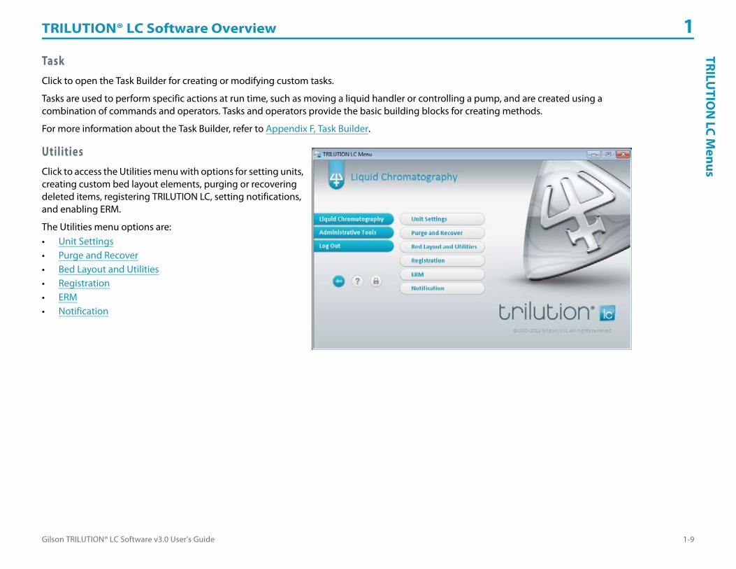
TaskClick to open the Task Builder for creating or modifying custom tasks.
Tasks are used to perform specific actions at run time, such as moving a liquid handler or controlling a pump, and are created using a combination of commands and operators. Tasks and operators provide the basic building blocks for creating methods.
For more information about the Task Builder, refer to Appendix F, Task Builder.
UtilitiesClick to access the Utilities menu with options for setting units, creating custom bed layout elements, purging or recovering deleted items, registering TRILUTION LC, setting notifications, and enabling ERM.
The Utilities menu options are:• Unit Settings• Purge and Recover• Bed Layout and Utilities• Registration• ERM• Notification

TRILUTION® LC Software Overview 1
1-10 Gilson TRILUTION® LC Software v3.0 User’s Guide
TRIL
UTI
ON
LC
Men
us Unit Settings
Click to access the Unit Settings dialog.
Members of the default Admin group can use Unit Settings to set the units of measurement for the commands and tasks and elsewhere in the software. Only users assigned to the Admin group have unit setting capabilities. Unit types are listed in the following table:
Unit Type Units of Measurement
XYZ Movement mm, cm
Data Level Not used
Ion Mass m/z
Atomic Mass amu
Amperage nA
Speed of Movement cm/sec, mm/hr, mm/min, mm/sec
Volume mL, nL, μL
Flow Rate mL/hr, mL/min, mL/sec, μL/min, μL/sec
Time hrs/min/sec
Pressure psi, MPa, Bar
Temperature C, F, K
Wavelength nm
Mass mg, μg

Gilson TRILUTION® LC Software v3.0 User’s Guide 1-11
TRILUTION® LC Software Overview 1TRILU
TION
LC Menus
Purge and Recover
Click to open the Purge and Recover utility.
Use the Purge and Recover utility window to permanently delete files from the database and/or restore deleted files back to their respective palettes.
It has the following buttons in the action bar:• Purge: Permanently deletes the files from the
database. Purged files cannot be recovered.• Recover: Provides the ability to restore files back to
their respective palettes. Files deleted from the database cannot be recovered.
Bed Layout and Utilities
Click to open the Bed Layout and Utilities window for creating custom templates and racks.
For more information, refer to Appendix G, Bed Layout and Utilities.
Registration
Click to open the Registration utility for generating registration information. Send this information to Gilson, Inc. to request a license for TRILUTION LC.
To register:
1 Complete all fields.2 E-mail or fax the registration information to Gilson, Inc.3 Overwrite the temporary license found in the
software’s CORE folder with the license file (called LSERVRC) received from Gilson, Inc.
TRILUTION® LC Software Overview 1
1-12 Gilson TRILUTION® LC Software v3.0 User’s Guide
TRIL
UTI
ON
LC
Men
us ERM
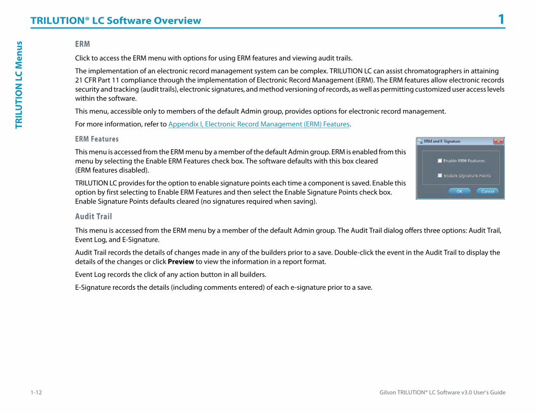
Click to access the ERM menu with options for using ERM features and viewing audit trails.
The implementation of an electronic record management system can be complex. TRILUTION LC can assist chromatographers in attaining 21 CFR Part 11 compliance through the implementation of Electronic Record Management (ERM). The ERM features allow electronic records security and tracking (audit trails), electronic signatures, and method versioning of records, as well as permitting customized user access levels within the software.
This menu, accessible only to members of the default Admin group, provides options for electronic record management.
For more information, refer to Appendix I, Electronic Record Management (ERM) Features.
ERM Features
This menu is accessed from the ERM menu by a member of the default Admin group. ERM is enabled from this menu by selecting the Enable ERM Features check box. The software defaults with this box cleared (ERM features disabled).
TRILUTION LC provides for the option to enable signature points each time a component is saved. Enable this option by first selecting to Enable ERM Features and then select the Enable Signature Points check box. Enable Signature Points defaults cleared (no signatures required when saving).
Audit Trail
This menu is accessed from the ERM menu by a member of the default Admin group. The Audit Trail dialog offers three options: Audit Trail, Event Log, and E-Signature.
Audit Trail records the details of changes made in any of the builders prior to a save. Double-click the event in the Audit Trail to display the details of the changes or click Preview to view the information in a report format.
Event Log records the click of any action button in all builders.
E-Signature records the details (including comments entered) of each e-signature prior to a save.

Gilson TRILUTION® LC Software v3.0 User’s Guide 1-13
TRILUTION® LC Software Overview 1TRILU
TION
LC Menus
Notification
Click to open the Select Notifications dialog.
The Notification utility allows for launching a file if a specified condition occurs. Those conditions are:• Run complete• No fraction sites available• Insufficient solvent volume available• Error condition met• Unit ID not found• Emergency Stop activated• Run terminated• Insufficient sample volume available• No fractions collected• Rack not found• Diagnostics
Execute
The format required to launch the file is the complete path, a hyphen, and then any arguments.
Notification Information
Optionally, send the notification message to a text file.
On the Browse for Folder window, select a folder and then click OK. On completion of the run, the notifications are saved in the specified folder with an .LCNT extension.
Clear Notification
Click to delete the notification message text files from the specified path folder.
ReportsClick to open the Reports window for generating the following report types: Task Report, Method Report, Project Report, Method Report, Sample Tracking Report, Analysis Report, Summary Report (Unknown or Standard), and Calibration Report.
For more information about reports, refer to Chapter 14, Reports.

TRILUTION® LC Software Overview 1
1-14 Gilson TRILUTION® LC Software v3.0 User’s Guide
TRIL
UTI
ON
LC
Men
us AboutClick to open the About screen, which displays the license information and provides access to the System Info.
Administrative ToolsThe Administrative Tools menu options are:• Change Password: Change passwords; refer to
Change Password.• Users and Groups: Create or modify Users and Groups;
refer to Users and Groups.• Settings: Change log on and/or log off settings; refer to
Settings.• Maintenance Alarms: Set reminders for maintaining the
system; refer to Maintenance Alarms.

Gilson TRILUTION® LC Software v3.0 User’s Guide 1-15
TRILUTION® LC Software Overview 1TRILU
TION
LC Menus
Change PasswordA member of the default Admin group provides the user name and the default password. Optionally, log on to the software and change your password from the Administrative Tools menu.
1 On the main menu, click Administrative Tools.2 On the Administrative Tools menu, click Change Password to display the
Change Password dialog.3 On the Change Password dialog:
a) In the Current User Name field, verify your user name.b) In the Current Password field, type your old password.c) In the New Password field, type a new password. The password is case-sensitive and has a 20-character limit.d) In the Confirm Password field, type the new password again. e) Click OK. The password is changed.

TRILUTION® LC Software Overview 1
1-16 Gilson TRILUTION® LC Software v3.0 User’s Guide
TRIL
UTI
ON
LC
Men
us Users and GroupsA User is an end user of the product. Every User is assigned to a Group based on their roles. A Group includes Users with common rights.
The Users and Groups menu allows for creating, modifying, deleting, and viewing Users and Groups.
By default, two groups are created during the software installation: Admin and Analyst. “Administrator” is the default user in the Admin group. The Admin group is assigned all the rights. “Analyst” is the default user in the Analyst group. The Analyst group can view, create, and modify in the software.
To open Users and Groups:
1 On the main menu, click Administrative Tools.2 On the Administrative Tools menu, click Users and Groups to display the Users and Groups window.
The Users and Groups window has two frames:• The left frame has two tabs:
a) Users: Create and modify Users.b) Groups: Create and modify Groups.
• The right frame displays the information based on the tab selected:a) When the Users tab is selected, the Group Name and the Group Description appear.b) When the Groups tab is selected, the User Name and the User Description appear.
Only members of the Admin group can create, modify, or delete Users and Groups.

Gilson TRILUTION® LC Software v3.0 User’s Guide 1-17
TRILUTION® LC Software Overview 1TRILU
TION
LC Menus
Groups
A group consists of users with common roles. Each role has assigned permissions.
The Groups tab lists all the available groups. Create, modify, or delete groups. After selecting a group from the Group tab, the users belonging to that group appear in the right frame.
For information about creating users, refer to Users.
How to Create a Group1 On the Users and Groups window, click the
Groups tab. The name of the default groups ‘Admin’ and ‘Analyst’ appear in the left frame.
2 Click Create to create a new group. The Create Group window appears.
3 In the Create Group window:a) In the Group Name field, type a new group name.b) In the Description field (optional), type a brief group description.c) In the Permissions frame, select the permissions for the various areas in the software.d) Click OK.
The new group is created and is listed on the Groups tab.
Modify a Group1 On the Users and Groups window, select a group from the Groups tab. The users belonging to that group appear in the right frame and the
Modify button is enabled.2 Click Modify to display the Modify Group window.3 In the Modify Group window, make the required changes and then click OK.
Delete a Group1 In the Groups tab, select a group and then click Delete. A delete confirmation dialog box appears.2 Click Yes. The selected group is deleted.
Note: The Admin group cannot be modified or deleted.

TRILUTION® LC Software Overview 1
1-18 Gilson TRILUTION® LC Software v3.0 User’s Guide
TRIL
UTI
ON
LC
Men
us How to View the Group Permissions
The Users and Groups tabs both provide the ability to view group permissions.
View Group Permissions Using the Users tab1 On the Users and Groups window, select a user from the Users tab. The assigned group names and descriptions for the user appear in the
right frame.2 Click Modify. The Modify User window appears.3 Select one or more groups and then click View Permissions.
• When multiple Groups are selected, a combination of all group permissions is displayed.• When one Group is selected, permissions for that specific group are displayed.
4 On the View Group Access Permissions window, view the following:a) In the Group Name field, the group name.b) In the Group Description field (optional), a brief description of the group.c) In the Permissions table, the permissions assigned to the group for the various areas of the software.d) Click OK.
Users
Users are assigned to groups based on their defined roles (i.e., Operator, Administrator, or Scientist).
The Users tab lists all the available users. Create, modify, or delete users.
Users can be assigned to one or more available groups. For information about creating groups, refer to Groups.

Gilson TRILUTION® LC Software v3.0 User’s Guide 1-19
TRILUTION® LC Software Overview 1TRILU
TION
LC Menus
How to Create a User1 On the Users and Groups window, click the Users tab. The default users ‘Administrator’
and ‘Analyst’ are displayed in the Users tab with the group name in the right frame.2 Click Create. The Create User window appears:3 On the Create User window:
a) In the User Name field, type a unique user name.b) In the User Description field (optional), type a brief description of the user.c) In the Password field, type the password.d) In the Confirm Password field, type the password for confirmation.e) In the Group field, select the group(s) the user is assigned to.
4 Click OK.
Modify a User Properties1 In the Users tab, select a user. The group name to which the user belongs, and the group
description are displayed in the right frame.2 Click Modify to display the Modify User window.3 In the Modify User window:
a) In the User Description field (optional), change the description.b) In the Password field, type a new password.
c) In the Confirm Password field, type the new password for confirmation.d) In the Group field, select the check box to add the user to a group or clear the check box to remove the user from a group.e) Click OK.
Delete a User1 In the Users tab, select a user and then click Delete to display a delete confirmation dialog box. 2 Click Yes. The selected user is deleted.
The password for the default user, Analyst, is Analyst.
A User name cannot be modified.

TRILUTION® LC Software Overview 1
1-20 Gilson TRILUTION® LC Software v3.0 User’s Guide
TRIL
UTI
ON
LC
Men
us Maintenance AlarmsA feature of the software is the ability to set one or more maintenance alarms.
Create an Alarm
To create a custom alarm:
1 Click Add.2 When the Alarm Name dialog appears, type a name and then click OK.3 Select a Start day and time, the recurrence (Period), and optionally, type a message.4 By default, any new alarms are turned On. Optionally, select Off to turn off an alarm
temporarily or permanently.5 Click Save.
Modify an Alarm
To modify an existing alarm:
1 Make desired changes to the alarm settings.2 Click Save.
Rename an Alarm
To rename an alarm:
1 Click Rename.2 Type the new name for the alarm.3 Click OK.4 Click Save.
SettingsThe Settings option in the Administrative Tools menu, accessible only to members of the default Admin group, enables setting global options for user log in and log out. It enables setting TRILUTION LC to remember the name of the last logged in user at each new log in and/or set TRILUTION LC to automatically log a user out after a successfully completed run. Locking the system voids the Automatic Log Out After Run selection.
The default is to remember the user name, but to keep the user logged in after a run.

Gilson TRILUTION® LC Software v3.0 User’s Guide 1-21
TRILUTION® LC Software Overview 1TRILU
TION
LC Menus
Log OutClick to end the current user’s session and allow a different user to log in to the software.
LockThe Lock option is for securing the software in its current state. All open, unsaved tasks or methods will remain open. Only the user who locked the system or a member of the default Admin group can log in when the software is locked. Lock voids an Automatic Log Off After Run setting.
Lock TRILUTION LC
1 On a menu, click the Lock button to display the Confirm Lock window.2 On the Confirm Lock window, click Lock to display the Unlock TRILUTION LC window.
Unlock TRILUTION LC1 On the Unlock TRILUTION LC window, in the Password field, type the password.2 Click Unlock.
Back
Click to return to the main menu.

TRILUTION® LC Software Overview 1
1-22 Gilson TRILUTION® LC Software v3.0 User’s Guide
GEA
RS GEARSThe Gilson Ethernet Asynchronous Remoting System (GEARS) is a mechanism for integrating third-party devices (RS-232) with any application that includes the proper implementation of Gilson’s Ethernet communication protocol. In short, a GEARS device appears as if it were a Gilson Ethernet device. GEARS devices may be created using the GEARS Configuration Utility, which is used to define device instruction sets and add the device to the TRILUTION database (adds device specific commands for use within the Task Builder, and provides a device that may be inserted into method configurations).
TRILUTION LC Backup UtilityThe TRILUTION LC Backup Utility, installed with TRILUTION LC Software, is used to create backup copies of the database, which can be restored, if desired.
Close TRILUTION LCClick on the main menu.

Gilson TRILUTION® LC Software v3.0 User’s Guide 2-1
Project Library 2
The Project Library is used for managing and organizing projects.
A project is a folder that contains:• applications• methods• results
Key concepts to understand about the Project Library are:• How to Create a Project• How to Share a Project• How to Export Projects• How to Import Projects• How to Create an Application• How to Export Applications• How to Import Applications

Project Library 2
2-2 Gilson TRILUTION® LC Software v3.0 User’s Guide
Proj
ectL
ibra
ryW
indo
w Project Library WindowThe Project Library serves as an organized, structured way to save and group applications and methods.
The Project Library window includes:• Applications Palette• Methods Palette• Action Buttons• Filter• Workspace• Info Window
Applications PaletteThe Applications palette lists the available applications.
For information on how to run an application, refer to How to Start a Run on page 9-2.

Gilson TRILUTION® LC Software v3.0 User’s Guide 2-3
Project Library 2ProjectLibrary
Window
Methods PaletteThe Methods palette lists the available methods.
For information on how to create a method, refer to How to Create a Method on page 3-6.
Filter
CriteriaLists the projects based on the filter selected.
ButtonsUse the following buttons to change the view or filter components in the Project Library:
Filter Description
Project Created by User Displays only the projects that the Current User has created.
All Projects for which the User has accessDisplays only the projects that have been created by or shared with the Current User. The exception is when the Current User is a member of the default Admin group. Those users see all projects created by all users.
For more information about sharing, refer to How to Share a Project.
Action Button
Description
Expands the view to display all projects, applications, and methods.
Collapses the view to show only the Projects branch.
Displays the Advanced Filter dialog in which projects can be filtered by created date, modified date, or run date within a specified date range.

Project Library 2
2-4 Gilson TRILUTION® LC Software v3.0 User’s Guide
Proj
ectL
ibra
ryW
indo
w WorkspaceForms the area to manage and organize projects.
Right-click MenuThe software employs the use of right-click options in the Project Library.
Project
Right-click on a Project icon ( ) in the Project Library to display the following menu options:
Menu Description
Change Description Modifies the short and/or long description for the project.
Paste
Adds the application from the clipboard to the project.
When an application is pasted, a dialog appears with options to link the application to other applications with the same name (Paste Same Copy) or rename the application.
When Paste Same Copy is selected, any changes to the application or its results are updated in all copies of that application. For example, if a method is removed from the original application, it will also be removed from the pasted application.
Save As Saves an existing project to a new name. Optionally, type a short and/or long description for the project.
DeleteDeletes the project if it does not have dependent applications.
For more information, refer to Delete a Project.
Create ApplicationCreates an application within the project. Optionally, type a short and/or long description for the application.
For more information, refer to How to Create an Application.
Share ProjectGrants permission to a user and/or group to access or import the project.
For more information, refer to How to Share a Project.

Gilson TRILUTION® LC Software v3.0 User’s Guide 2-5
Project Library 2ProjectLibrary
Window
Application
Right-click on an Application icon ( ) in the Project Library to display the following menu options:
Menu Description
Change Description Modifies the short and/or long description for the application.
Copy Copies the application to the clipboard.
Paste Adds the method from the clipboard to the application.
Save As Saves an existing application to a new name. Optionally, type a short and/or long description for the application.
Run Opens the Application Run Window.
ResultsOpens the Results window.
For more information about results, refer to Chapter 11, Results.
Remove from Project Removes the application from the project and places it in the Applications palette.
DeleteDeletes the application if it does not have dependent methods or results.
For more information, refer to Delete an Application.
Create Method Opens the Method Builder to create a method within the application.
Enable Open Access Allows the application to be accessible in TRILUTION LC Open Access. Applications enabled for Open Access use the following icon: .
For more information about Open Access, refer to Appendix H, Open Access.
Disable Open AccessMarks an Open Access Application inaccessible in TRILUTION LC Open Access.
For more information about Open Access, refer to Appendix H, Open Access.
Minimum Fraction SitesSets the minimum number of fraction sites required for each injection when the application is enabled for Open Access.
For more information about Open Access, refer to Appendix H, Open Access.
Disable Placement SafetyPlacement Safety defaults enabled. When placement safety is disabled, Open Access users will be prompted to place samples even if the instrument is running.
For more information about Open Access, refer to Appendix H, Open Access.

Project Library 2
2-6 Gilson TRILUTION® LC Software v3.0 User’s Guide
Proj
ectL
ibra
ryW
indo
w Method
Right-click on a Method icon ( ) in the Project Library to display the following menu options:
Spectral Library
Right-click on a Spectral Library icon in the Project Library to display the following menu options:
Menu Description
Copy Copies the method to the clipboard.
Open Opens the method in the Method Builder.
Remove from Application Removes the method from the application and places it in the Methods palette.
DeleteDeletes the method or all versions of the method.
For more information, refer to Delete Methods on page 3-13.
Default Method Sets the selected method’s configuration, bed layouts, control error handling (but NOT the control), analyses, and analysis error handling as default for all new methods created. Method name will then appear in bold.
Application Default Sets the selected method’s configuration as the default Method Configuration in the Application Run window.
Menu Description
Open Opens the spectral library.
Delete Deletes the spectral library.
Gilson TRILUTION® LC Software v3.0 User’s Guide 2-7
Project Library 2ProjectLibrary
Window
Action ButtonsThe following action buttons are located in the lower left corner of the Project Library:
Info WindowThe Info Window displays the Current User, Name, Created Date, Created By, Last Modified Date, Last Modified By, Short Description, and Long Description.
Action Button Description
Create ProjectCreates a new project.
For more information, refer to How to Create a Project.
RunRuns the selected application.
For more information, refer to Chapter 9, Running an Application.
Refresh Reloads the palettes with any new applications or methods created or imported.
ExportCopies a project to a specified location as a .LCPE file or copies an application to a specified location as a .LCAE file.
For more information, refer to How to Export Projects or How to Export Applications.
Import
Imports a .LCAE file and lists the application in the Applications palette in the Project Library or imports a .LCPE file and displays the project in the Project Library workspace.
Imported components will not appear until the window is refreshed.
For more information, refer to How to Import Projects or How to Import Applications.

Project Library 2
2-8 Gilson TRILUTION® LC Software v3.0 User’s Guide
Proj
ect Project
The following sections describe:• How to Create a Project• How to Share a Project• How to Modify a Project• How to Export Projects• How to Import Projects• How to Delete a Project
How to Create a Project1 On the Liquid Chromatography menu, select Project Library.2 In the Project Library, do either of the following:
a) Click Create Project to display the New Project dialog.b) Right-click on the workspace and then select Create Project.
3 In the New Project dialog:a) In the Project Name field, type a name.b) In the Short Description field (optional), type a brief description of the
project.c) In the Long Description field (optional), type a detailed description of
the project.d) Click OK. The Project Library is refreshed with the new project listed in the
workspace.

Gilson TRILUTION® LC Software v3.0 User’s Guide 2-9
Project Library 2Project
4 To add an application to the project, do either of the following:• Right-click on the project and then select Create Application to display
the New Application dialog.1) In the Application Name field, type a name.2) In the Short Description field (optional), type a brief description
of the application.3) In the Long Description field (optional), type a detailed
description of the application.4) Click OK. The Project Library is refreshed with the new application
listed in the Applications palette and in the project.• From the Applications palette, drag an application into the workspace
and then drop it in the project to be given the option to link the application to other applications with the same name (Paste Same Copy) or rename the application.When Paste Same Copy is selected, any changes to the application or its results are updated in all copies of that application. For example, if a method is removed from the original application, it will also be removed from the pasted application.
5 To add a method to the application, do one of the following:• Right-click on the application and then select Create Method. The
Method Builder opens.• From the Methods palette, drag a method into the workspace and then drop it in the application.• Drag a method from an existing application and then drop it in the application.

Project Library 2
2-10 Gilson TRILUTION® LC Software v3.0 User’s Guide
Proj
ect How to Share a Project
To enable other users to view or modify a project, it must be shared. Once shared, the logged in user can act on the project per the permissions assigned to that user’s group. For example, a user with the Modify Project Library permission can make changes to a project that has been shared with him.
Projects are automatically shared with all members of the default Admin group and can be accessed by those members by selecting “All projects for which user has access” filter criteria. Only members of the default Admin group can unshare a project with other members of the default Admin group.
To share a project:
1 In the Project Library, right-click the project to be shared, and then select Share Project.2 From the drop-down list of Groups, select the group with which the project should be shared.3 After the group is selected, the list of users in that group appears. Select the check box next to each user with
whom the project should be shared.4 Click Update.5 Repeat for each additional group.
Modify a ProjectTo modify a project, do any of the following:• Change a Description• Add Applications• Remove Applications• Change the Share settings. (How to Share a Project)
Change a DescriptionTo change the description after the project has been created:
1 Right-click on the project and then select Change Description.2 In the Short Description field (optional), type a brief description of the project.3 In the Long Description field (optional), type a detailed description of the project.

Gilson TRILUTION® LC Software v3.0 User’s Guide 2-11
Project Library 2Project
Add ApplicationsFrom the Applications palette, drag an application into the workspace and then drop it in the project to be given the option to link the application to other applications with the same name (Paste Same Copy) or rename the application.
When Paste Same Copy is selected, any changes to the application or its results are updated in all copies of that application. For example, if a method is removed from the original application, it will also be removed from the pasted application.
Remove ApplicationsAn application can be removed from a project without deleting the application. To remove an application, right-click on the application and then select Remove from Project. The application is removed from the project, but remains in the Applications palette.
How to Export Projects1 In the Project Library, click Export to display the Export window.2 In the Export window:
a) Click to display projects.b) In the Select the items to be exported field, select the projects.c) In the Select a path field, do either of the following:
• Accept the default path of C:\Documents and Settings\OS User Name\My Documents\TRILUTION LC x.x\Export.
• Click to display the Browse For folder window. On the Browse For folder window, select a folder and then click OK.
Note: You must have permission to write to the folder.3 Click OK. On completion of the export operation, the project (including the
applications and methods, but not results) is saved in the specified folder with a .LCPE extension.
4 When the export success/fail dialog appears:• Click Details to view the log information of the export operation.• Click OK.
If a project with the same name is found in the export path, an option is provided to rename or overwrite the project or to skip the export operation for that project.

Project Library 2
2-12 Gilson TRILUTION® LC Software v3.0 User’s Guide
Proj
ect How to Import Projects
1 In the Project Library, click Import to display the Import window.2 From the Import window:
a) Browse for and select one or more Project Export Files (.LCPE).b) Click Open.
3 When the import success/fail dialog appears:• Click Details to view the log information of the import operation.• Click OK.
System ConflictsIf components within the project being imported already exist with the same name on the system, a dialog appears listing those components.
By default, all components are set to be renamed from Name to New Name on click of Import. • Optionally, modify the New Name:
a) Click to highlight in the cell in the New Name column for the component name to be changed.
b) Click in the cell again to activate the editing function.c) Type the new name.d) Press Enter or click off the cell to accept.e) Click Import.
• Or, change the status to Overwrite by doing either of the following:• Click Overwrite All and then click Import to overwrite all listed components. • Right-click the component name, select Overwrite, and then click Import to overwrite only the component selected.
To change the status of all components back to Rename, click Rename All.
When the import success/fail dialog appears:• Click Details to view the log information of the import operation.• Click OK.
Before overwriting a component, it is good practice to review where that component is used. Right-click the component name and then select Where Used to display this information.

Gilson TRILUTION® LC Software v3.0 User’s Guide 2-13
Project Library 2Project
Delete a ProjectTo delete a project:
1 Select a project and then right-click to view the submenu. On the submenu, click Delete.2 On the Delete confirmation dialog box, click Yes. The project is deleted. Use the Purge and Recover utility to permanently delete the project.
A project cannot be deleted if it contains applications. Remove or delete associated applications before attempting to delete the project.

Project Library 2
2-14 Gilson TRILUTION® LC Software v3.0 User’s Guide
App
licat
ion Application
The following sections describe:• How to Create an Application• How to Export Applications• How to Import Applications
How to Create an ApplicationAn application contains methods and results. Run applications to obtain results.
1 Right-click on the project and then select Create Application to display the New Application dialog.a) In the Application Name field, type a name.b) In the Short Description field (optional), type a brief description of the
application.c) In the Long Description field (optional), type a detailed description of the
application.d) Click OK. The Project Library is refreshed with the new application listed in
the Applications palette and in the project.
Modify an ApplicationTo modify an application, do any of the following:• Change a Description• Add Methods• Remove Methods
Change a DescriptionTo change the description after the application has been created:
1 Right-click on the application and then select Change Description.2 In the Short Description field (optional), type a brief description of the application.3 In the Long Description field (optional), type a detailed description of the application.

Gilson TRILUTION® LC Software v3.0 User’s Guide 2-15
Project Library 2A
pplication
Add MethodsTo add a method to an application, do any of the following:• From the Methods palette, drag a method into the workspace and then drop it in the application.• Drag a method from one application and then drop it in another.• Right-click on a method and then select Copy and then right-click on the application and then select Paste.
Any changes to the method are updated in all copies of that method. For example, if the fraction collection settings are modified in the original method, they will also be modified in the pasted method.
Remove MethodsA method can be removed from an application without deleting the method. To remove a method, right-click on the method and then select Remove from Application. The method is removed from the application, but remains in the Methods palette.
How to Export Applications1 In the Project Library, click Export to display the Export window.2 In the Export window:
a) Click to display applications.b) In the Select the items to be exported field, select the applications.c) In the Select a path field, do either of the following:
• Accept the default path of C:\Documents and Settings\OS User Name\My Documents\TRILUTION LC x.x\Export.
• Click to display the Browse For folder window. On the Browse For folder window, select a folder and then click OK.
Note: You must have permission to write to the folder.3 Click OK. On completion of the export operation, the application and methods, but
not results are saved in the specified folder with a .LCAE extension.
4 When the export success/fail dialog appears:• Click Details to view the log information of the export operation.• Click OK.
If an application with the same name is found in the export path, an option is provided to rename or overwrite the application or to skip the export operation for that application.

Project Library 2
2-16 Gilson TRILUTION® LC Software v3.0 User’s Guide
App
licat
ion How to Import Applications
1 In the Project Library, click Import to display the Import window.2 From the Import window:
a) Browse for and select one or more Application Export Files (.LCAE).b) Click Open.
3 When the import success/fail dialog appears:• Click Details to view the log information of the import operation.• Click OK.
System ConflictsIf components within the application being imported already exist with the same name on the system, a dialog appears listing those components:
By default, all components are set to be renamed from Name to New Name on click of Import. • Optionally, modify the New Name:
a) Click to highlight in the cell in the New Name column for the component name to be changed.
b) Click in the cell again to activate the editing function.c) Type the new name.d) Press Enter or click off the cell to accept.e) Click Import.
• Or, change the status to Overwrite by doing either of the following:• Click Overwrite All and then click Import to overwrite all listed components. • Right-click the component name, select Overwrite, and then click Import to overwrite only the component selected.
To change the status of all components back to Rename, click Rename All.
When the import success/fail dialog appears:• Click Details to view the log information of the import operation.• Click OK.
Before overwriting a component, it is good practice to review where that component is used. Right-click the component name and then select Where Used to display this information.

Gilson TRILUTION® LC Software v3.0 User’s Guide 2-17
Project Library 2View
Results
Delete an ApplicationTo delete an application:
1 Select an application and then right-click to view the submenu. On the submenu, click Delete.2 On the Delete confirmation dialog box, click Yes. The application, and any associated sample lists, are deleted. Use the Purge and Recover
utility to permanently delete the application.
View ResultsTo view results, do either of the following:• Right-click on an application and then select Results.
• Double-click the Results icon ( ).
For more information about results, refer to Chapter 11, Results.
An application cannot be deleted if it contains methods or results. Remove or delete associated methods and archive results before attempting to delete the application.
Gilson TRILUTION® LC Software v3.0 User’s Guide 3-1
Method Builder 3
To begin creating a method, select Method from the Liquid Chromatography menu.
Key concepts to understand about the Method Builder are:
• How to Create a Method
• How to Save a Method
• How to Export Methods
• How to Import Methods

Method Builder 3
3-2 Gilson TRILUTION® LC Software v3.0 User’s Guide
Met
hod
Build
er W
indo
w Method Builder WindowUsing the options in the Method Builder, specify the configuration, a bed layout, method conditions for controlling instruments (Control), and analysis parameters (Analysis).
The Method Builder window includes:• Configuration Tab• Bed Layout Tab• Control Tab• Analysis Tab• Configured Instruments Panel• Action Buttons• Info Window
Configuration TabFor details about this tab and how to create a configuration, refer to Chapter 4, Method Builder - Configuration.
Bed Layout TabFor details about this tab and how to select racks and number tubes to create a bed layout, refer to Chapter 5, Method Builder - Bed Layout.
Control TabFor details about this tab and how to add tasks and a gradient to a method, refer to Chapter 6, Method Builder - Control.
Analysis TabFor details about this tab and how to create analyses, refer to Chapter 7, Method Builder - Analysis.

Gilson TRILUTION® LC Software v3.0 User’s Guide 3-3
Method Builder 3M
ethodBuilder W
indow
Configured Instruments PanelThis panel is used to provide information and for navigation. Information provided is dependent on the instrument type and right-click options are available for each item (refer to Right-click Menu). Click any instrument name to display the configuration property page for that instrument. Click any bed layout name to navigate to the Bed Layout tab and display that bed layout. Click any analysis name to navigate to the Analysis tab and display that analysis.
Right-click Menu
Configuration or Bed Layout
Right-click on a configuration name or bed layout name to display the following menu options:
Analysis
Right-click on an analysis name to display the following menu options:
Instrument
Right-click on an instrument name to display the following menu options:
Menu Description
NewFor a configuration, navigates to the Configuration tab, clears the workspace, and displays a unique name for the new configuration.
For a bed layout, displays the Select Template dialog, which provides a filtered list of templates for the selected instrument. After selecting a template and then clicking OK, navigates to the Bed Layout tab and displays a unique name for the new bed layout.
Browse
For a configuration, displays the Browse Configuration dialog listing all configurations. After selecting a configuration and then clicking OK, navigates to the Configuration tab and displays the browsed configuration.
For a bed layout, displays the Select Bed Layout dialog listing all bed layouts. After selecting a bed layout, optionally click Where Used and then select the bed layout again on the Where Used dialog to refer to which methods use the selected bed layout. Click OK to exit the Where Used dialog and then click OK to accept the bed layout selection, navigate to the Bed Layout tab, and display the browsed bed layout.
Rename Activates inline editing to change the name of the component and thereby break the shared component link, if applicable.
Menu Description
Default Analysis Default Analysis is a toggle option. When toggled on, the selected analysis will be used to analyze the data from the selected data channel during the run.
Rename Analysis Activates inline editing to change the name of the analysis.
Remove Analysis Disassociates the selected analysis from the selected data channel.
Menu Description
Rename Instrument Activates inline editing to change the name of the instrument.
Remove Instrument Deletes the selected instrument from the configuration and thereby causes a conflict in a shared configuration when attempting to save the method, if applicable.
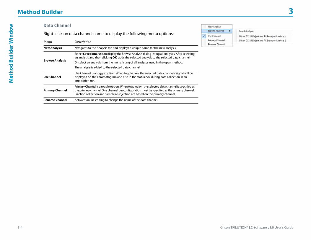
Method Builder 3
3-4 Gilson TRILUTION® LC Software v3.0 User’s Guide
Met
hod
Build
er W
indo
w Data Channel
Right-click on data channel name to display the following menu options:
Menu Description
New Analysis Navigates to the Analysis tab and displays a unique name for the new analysis.
Browse Analysis
Select Saved Analysis to display the Browse Analysis dialog listing all analyses. After selecting an analysis and then clicking OK, adds the selected analysis to the selected data channel.
Or select an analysis from the menu listing of all analyses used in the open method.
The analysis is added to the selected data channel.
Use ChannelUse Channel is a toggle option. When toggled on, the selected data channel’s signal will be displayed on the chromatogram and also in the status box during data collection in an application run.
Primary ChannelPrimary Channel is a toggle option. When toggled on, the selected data channel is specified as the primary channel. One channel per configuration must be specified as the primary channel. Fraction collection and sample re-injection are based on the primary channel.
Rename Channel Activates inline editing to change the name of the data channel.

Gilson TRILUTION® LC Software v3.0 User’s Guide 3-5
Method Builder 3M
ethodBuilder W
indow
Action ButtonsThe following action buttons are located in the lower left corner of the Method Builder:
Info WindowThe info window lists information about the open method.
Action Button Description
New Creates a new method. For more information, refer to How to Create a Method.
OpenOpens an existing method. The Default Method (if applicable) appears bold.
For more information, refer to View a Method.
SaveSaves an existing method to the same name.
For more information, refer to How to Save a Method.
Save As Saves a new method or save an existing method to a new name. Optionally, type a short and/or long description for the method.
DeleteOpens the Delete Method dialog for selecting and deleting one or all versions of a method or methods.
For more information, refer to Delete Methods.
ExportExports the method to a specified location as a .LCME file.
For more information, refer to How to Export Methods.
ImportImports a .LCME file and lists the method in the Methods palette in the Project Library or replaces it in the application.
For more information, refer to How to Import Methods.
Refresh Reloads the Tasks palette with the latest tasks, including any new tasks created, and applies any changes to the unit settings.
Run
Opens the Application Run window.
If the method is in multiple applications, the software first prompts to select which application to run and then opens the Application Run window.
For more information, refer to Chapter 8, Application Run.

Method Builder 3
3-6 Gilson TRILUTION® LC Software v3.0 User’s Guide
How
to C
reat
e a
Met
hod How to Create a Method
The following provides an overview of the steps to create a method.
1 To begin creating a method, do one of the following:• Select Method from the Liquid Chromatography menu.• Open an existing method and then click New.• Right-click on an application in the Project Library and then select Create Method.
2 Create a configuration. For more information, refer to How to Create a Configuration on page 4-4.3 Create a bed layout. For more information, refer to How to Create a Bed Layout on page 5-4.4 Add a mobile phase template. For more information, refer to How to Create Gradient or Isocratic Conditions on page 6-13.5 Add a fraction collection task and set the fraction collection parameters. For more information, refer to Fraction Collection Settings on
page A-167 or Conditional Fraction Collection on page A-152.6 Add a detector settings task. For more information, refer to 151 152 Detector Settings on page A-74, 155 156 Detector Settings on page A-75,
or 171 172 Detector Settings on page A-78.7 Add a task to autozero the detector. For more information, refer to Detector Autozero Channel on page A-154 or 506C Autozero Channel on
page A-131. 8 Add an injection task and set the injection task parameters. For more information, refer to Appendix A, List of Tasks. 9 Add a synchronize to sync 1 in the injection task. For more information, refer to Sync on page A-389. 10 Add the Start Data Collection task. For more information, refer to Start Data Collection on page A-382.11 Add a synchronize to the end of the injection task. For more information, refer to Sync on page A-389. 12 Add the Start Fraction Collection task. For more information, refer to Start Fraction Collection on page A-383. 13 Add the Stop Fraction Collection task. For more information, refer to Stop Fraction Collection on page A-387. 14 Add the Stop Data Collection task. For more information, refer to Stop Data Collection on page A-385.
Required minimum time between tasks in a method is 0.02 min before Start Data Collection and 0.1 min after Start Data Collection. Separate tasks to the same instrument by a minimum of 0.1 min.

Gilson TRILUTION® LC Software v3.0 User’s Guide 3-7
Method Builder 3H
ow to Save a M
ethod
How to Save a MethodTo run a method, it must be saved. When finished creating the method, click Save.
Three scenarios are possible and each displays different information during the save.• If the method does not use any shared components or shared components have not been modified, refer to Basic Save for more
information.• If the method uses shared components that have been modified, but those modifications do not cause a conflict (i.e., adding an
instrument to the configuration not requiring a bed layout, modifying a bed layout while keeping all zone names, or modifying an analysis, etc.), refer to Save Method Using Shared Components <OK to Update> for more information.
• If the method uses shared components that have been modified and those modifications cause a conflict (i.e., removing any instrument from the shared configuration, adding an instrument to the shared configuration that requires a bed layout, removing zones from a shared bed layout, or referencing an error method in the shared analysis that is used in a method selected to be used for error handling), refer to Save Method Using Shared Components <Cannot Update> for more information.
After the method has been saved, the Run button is active. Click Run to open the Application Run window. If the method is in multiple applications, the software first prompts to select which application to run and then opens the Application Run window. For more information, refer to Chapter 8, Application Run.
Basic SaveIf the method does not use any shared components or shared components have not been modified, the Save Method dialog looks similar to that shown.
Do the following:
1 Type a name for the method in the Name field or accept the unique default name provided.
2 Optionally, type a short and/or long description.3 Select the applications to which this method will be
saved. If no applications are selected, the method will be saved and will appear in the Methods palette in the Project Library.
4 Optionally, select the Default Method check box to set the method’s configuration, bed layouts, control error handling (but NOT the control tasks), analyses, and analysis error handling as default for all new methods created.
5 Optionally, select the Use for Error Handling check box to indicate that the method should be available for selection as an error method in an error condition. Methods used for error handling cannot reference another method in an error handling condition.

Method Builder 3
3-8 Gilson TRILUTION® LC Software v3.0 User’s Guide
How
to S
ave
a M
etho
d Save Method Using Shared Components <OK to Update>If the method uses shared components that have been modified, but those modifications do not cause a conflict, the Save Method dialog indicates that the Update Status is <OK to Update> and the dialog looks similar to that shown.
Examples of modifications that would set the Update Status to <OK to Update> are: • adding an instrument not requiring a bed layout• modifying a bed layout while keeping all zone names• modifying an analysis.
For more details about which components were modified and the methods that will be affected, click Details. A dialog similar to that shown appears.
Optionally, cancel out of the save and then rename components to break the shared component link (refer to Configured Instruments Panel). Follow the steps described for the Basic Save.

Gilson TRILUTION® LC Software v3.0 User’s Guide 3-9
Method Builder 3H
ow to Save a M
ethod
Save Method Using Shared Components<Cannot Update>If the method uses shared components that have been modified and those modifications cause a conflict, the Save Method dialog indicates that the Update Status is <Cannot Update> and the dialog is similar to that shown.
Examples of modifications that would set the Update Status to <Cannot Update> are:• removing any instrument from the
shared configuration• adding an instrument to the shared
configuration that requires a bed layout• removing zones from a shared
bed layout• referencing an error method in the
shared analysis that is used in a method selected to be used for error handling
For more details about the modifications that were made and the methods that will be affected, click Details. A dialog similar to that shown appears.
Cancel out of the save and then rename affected components causing a conflict to break the shared component link (refer to Configured Instruments Panel). Resolve any conflicts and then save the method.

Method Builder 3
3-10 Gilson TRILUTION® LC Software v3.0 User’s Guide
View
a M
etho
d View a Method1 In the Method Builder, click Open to display the Open Method window.
The Default Method (if applicable) appears bold.Select the Show Versions check box to see all versions of all methods.
2 In the Open Method window, select a method and then click OK. The method appears in the workspace.

Gilson TRILUTION® LC Software v3.0 User’s Guide 3-11
Method Builder 3H
ow to Export M
ethods
How to Export Methods1 In the Method Builder, click Export to display the Export window.2 In the Export window:
a) In the Select the items to be exported field, select the methods.Select the Show Versions check box to see all versions of all methods.
b) In the Select a path field, do either of the following:• Accept the default path of C:\Documents and Settings\OS User Name\
My Documents\TRILUTION LC x.x\Export.
• Click to display the Browse For folder window. On the Browse For folder window, select a folder and then click OK. Note: You must have permission to write to the folder.
3 Click OK. On completion of the export operation, the method (with its embedded tasks and error handling methods) is saved in the specified folder with a .LCME extension.
4 When the export success/fail dialog appears:• Click Details to view the log information of the export operation.• Click OK.
If a method with the same name is found in the export path, an option is provided to rename or overwrite the method or to skip the export operation for that method only.

Method Builder 3
3-12 Gilson TRILUTION® LC Software v3.0 User’s Guide
How
to Im
port
Met
hods How to Import Methods
1 In the Method Builder, click Import to display the Import window.2 From the Import window:
a) Browse for and select the Method Export files (.LCME).b) Click Open.
3 When the import success/fail dialog appears:• Click Details to view the log information of the import operation.• Click OK.
System ConflictsIf components, custom tasks, or error method within the method being imported already exist with the same name on the system, a dialog appears listing those components.
By default, all components are set to be renamed from Name to New Name on click of Import. • Optionally, modify the New Name:
a) Click to highlight in the cell in the New Name column for the component name to be changed.
b) Click in the cell again to activate the editing function.c) Type the new name.d) Press Enter or click off the cell to accept.e) Click Import.
• Or, change the status to Overwrite by doing either of the following:• Click Overwrite All and then click Import to overwrite all listed components. • Right-click the component name, select Overwrite, and then click Import to overwrite only the component selected.
To change the status of all components back to Rename, click Rename All.
When the import success/fail dialog appears:• Click Details to view the log information of the import operation.• Click OK.
Before overwriting a component, it is good practice to review where that component is used. Right-click the component name and then select Where Used to display this information.
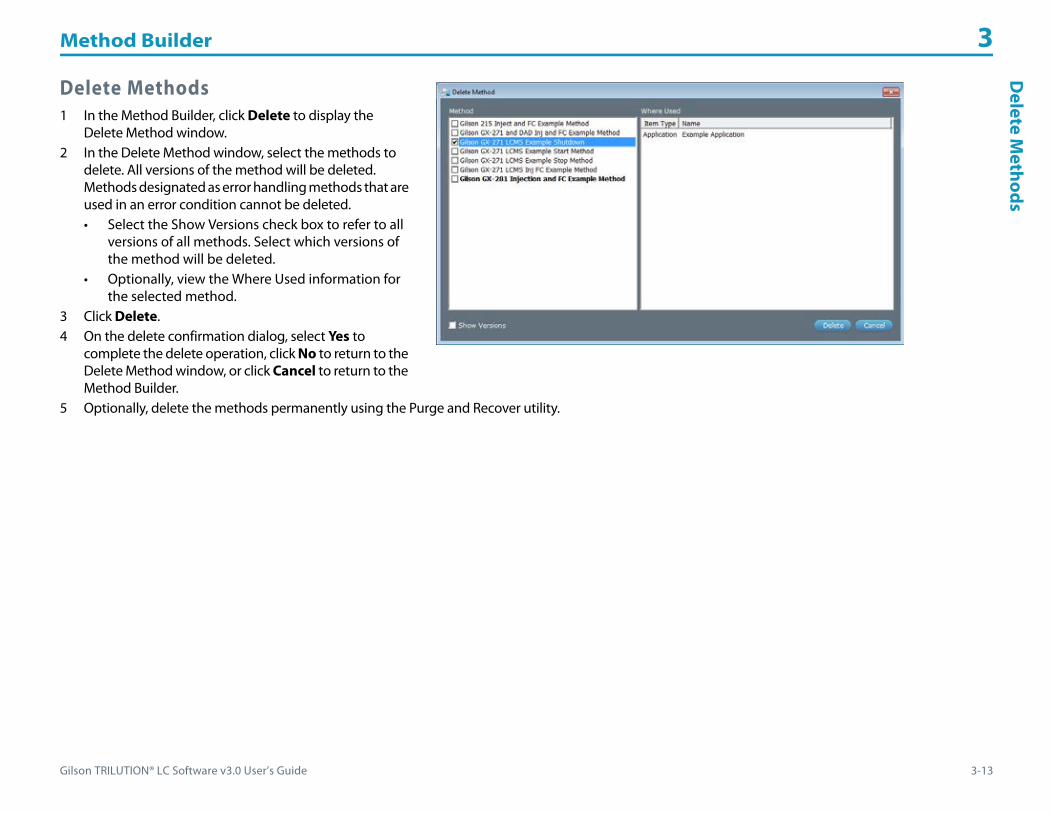
Gilson TRILUTION® LC Software v3.0 User’s Guide 3-13
Method Builder 3D
elete Methods
Delete Methods1 In the Method Builder, click Delete to display the
Delete Method window.2 In the Delete Method window, select the methods to
delete. All versions of the method will be deleted. Methods designated as error handling methods that are used in an error condition cannot be deleted.• Select the Show Versions check box to refer to all
versions of all methods. Select which versions of the method will be deleted.
• Optionally, view the Where Used information for the selected method.
3 Click Delete.4 On the delete confirmation dialog, select Yes to
complete the delete operation, click No to return to the Delete Method window, or click Cancel to return to the Method Builder.
5 Optionally, delete the methods permanently using the Purge and Recover utility.
Method Builder 3
3-14 Gilson TRILUTION® LC Software v3.0 User’s Guide
Clos
e th
e M
etho
dBu
ilder Close the Method Builder
In the Method Builder, do either of the following:
• Click in the lower right corner to return to the main menu.
• Click in the upper right corner to close the Method Builder.

Gilson TRILUTION® LC Software v3.0 User’s Guide 4-1
Method Builder - Configuration 4
A configuration consists of a group of uniquely named instruments. The configuration is part of a method.
The drag-and-drop feature enables easy creation of configurations by dragging an instrument and dropping it into the workspace.
For information about how to create a configuration, refer to How to Create a Configuration.

Method Builder - Configuration 4
4-2 Gilson TRILUTION® LC Software v3.0 User’s Guide
Conf
igur
atio
n Ta
bW
indo
w Configuration Tab WindowThe Configuration tab window in the Method Builder is a graphical interface used to create a configuration.
The Configuration tab window includes:• Instrument Types• Available Instruments• Workspace• Available Instruments
For information about how to create a configuration, refer to How to Create a Configuration.
Instrument TypesLists the available instrument groups.
WorkspaceThe Workspace is an area used to create or view a configuration and display the configuration name.

Gilson TRILUTION® LC Software v3.0 User’s Guide 4-3
Method Builder - Configuration 4Configuration Tab
Window
Available InstrumentsLists the instruments of the selected instrument group or those identified during the scan.
PropertiesArea used to view and/or edit instrument properties.
Instruments are grouped by type on the Configuration tab of the Method Builder.
Each instrument has a set of properties unique to that instrument.
The set of properties for an instrument may include one or more of the following tabs:
The instrument types are:• Detector• Fraction Collector• Injector• Liquid Handler• Mobile Phase• Switching Valve• Communication• Syringe Pump
For information about how to create a configuration, refer to How to Create a Configuration.
Tab Description
Setup Provide specific information about the instrument to the software.
Units Provide information about the scale to be used and label for user-defined data units.
Contacts Name input and output contacts. This information will be used to identify the contact in a task.
General Enter the instrument name and GSIOC ID or serial numbers. This information will be used to identify the instrument in a task and to the software.

Method Builder - Configuration 4
4-4 Gilson TRILUTION® LC Software v3.0 User’s Guide
How
to C
reat
e a
Conf
igur
atio
n How to Create a Configuration1 In the Method Builder, select the Configuration tab.2 Right-click on the configuration name in the Configured Instruments panel, select New Configuration, and then do either of the following:
• From the Instrument Types, select an instrument group (Detector, Fraction Collector, Injector, Liquid Handler, Mobile Phase, Switching Valve, Communication, or Syringe Pump). The instruments in that group are listed in the Available Instruments window.
• Click Scan. The software searches for Gilson GSIOC and Ethernet instruments. 3 From the Available Instruments window, drag an instrument and then drop it in the workspace. Set the properties for the instruments to
match your configuration.
4 If a data instrument (Detector or Communication) will be used,:a) Right-click on a data channel marked for use and then select Primary Channel. One channel per configuration must be specified as the
primary channel. Fraction collection and sample re-injection are based on the primary channel.b) Right-click on a data channel in the Configured Instruments panel and then do one of the following:
• Select New Analysis. Optionally, set the peak integration, report, and error handling options for the analysis. Refer to Chapter 7, Method Builder - Analysis for details.
• Select Browse Analysis and then Saved Analysis to associate an existing analysis from any method to the data channel. Any changes to the analysis will be reflected in all copies of the analysis with the same name in any method.
• Select Browse Analysis to associate an existing analysis from the current method to the data channel. Any changes to the analysis will be reflected in all copies of the analysis with the same name.
Optionally, right-click on a data channel and then select Rename Channel to rename the data channel.Click the Configuration tab and repeat step b for any additional data channels.
c) Right-click on an analysis and then select Default Analysis to specify which analysis TRILUTION LC will use during the run for the associated data channel.
d) Optionally, right-click on an analysis and then select Rename Analysis to rename the analysis.5 Optionally, right-click on the configuration name in the Configured Instruments panel and then select Rename Configuration to rename
the configuration. By default, each new configuration is given a unique name. Gilson recommends using unique names for configurations.
Each instrument in a Gilson system must have a unique GSIOC ID.

Gilson TRILUTION® LC Software v3.0 User’s Guide 4-5
Method Builder - Configuration 4H
ow to Create a Configuration
Detector
151 Detector 152 Detector
155 Detector 156 Detector
171 DAD 172 DAD
Flexar SQ 300 MS Detector Virtual Detector
Detector Properties
Name Brief Description Default Value Range
151 Detector, 152 Detector, 155 Detector, 156 Detector
Data Channels
Optionally, type a unique description for each data channel. This description and the data channel’s signal will be displayed in the status box while Data are being collected during an application run if the Use check box is selected for that data channel. The Use check box for Data Channel 1 defaults selected. There are three data channels available (labeled 15X Channel 1, 15X Channel 2, 15X Channel 3, where X is 1, 2, 5, or 6 dependent on the model of the detector).
The maximum number of channels per configuration that can be used is eight.
151 Channel 1152 Channel 1155 Channel 1156 Channel 1
N/A
Data Rate (points/sec) The number of data points collected per second for the channel. Optionally, set a different data rate for each channel. 20 1–80
Units
The user unit that corresponds to the mV value indicated and the label for those units.
Data scaled, plotted, and analyzed according to selected these units. All calculations (i.e., heights and areas) are reported according to these units. Units are shown on the graph axis (while running and in reports). Multiple graph axes are displayed if different user units are set for different data channels. A symbol is displayed on the graph axis to indicate which data channel is using that axis.
1 mV = 1 mV N/A
Instrument Name The name that will be used to identify this instrument in a task. Detector N/A
GSIOC IDA unique numerical address that must be known to the instrument and to the software that allows the software to communicate with the instrument. 16 10–19
Detector Properties (Page 1 of 2)

Method Builder - Configuration 4
4-6 Gilson TRILUTION® LC Software v3.0 User’s Guide
How
to C
reat
e a
Conf
igur
atio
n
171 DAD, 172 DAD
Data Channels
Optionally, type a unique description for each data channel. This description and the data channel’s signal will be displayed in the status box while Data are being collected during an application run if the Use check box is selected for that data channel. The Use check box for Data Channel 1 defaults selected. There are eight data channels available (labeled 17X Channel 1 through 17X Channel 8, where X is 1 or 2 dependent on the model of the detector).
The maximum number of channels per configuration that can be used is eight.
171 Channel 1172 Channel 1
N/A
Data Rate (points/sec)The number of data points collected per second for all channels. One rate is set for all channels.
The recommended setting is between 5 and 10 points/sec.10 1–10
ContactsOptionally, type a description for the contact. This description and the contact’s status will be displayed at all times in the status box during an Application Run. There are two Outputs available (labeled 1, 2) and two Inputs available (labeled A, B).
N/A N/A
Instrument Name The name that will be used to identify this instrument in a task. Detector N/A
Instrument Serial Number The serial number of the detector. N/A N/A
Flexar SQ 300 MS Detector
Data Channels
Optionally, type a unique description for each channel. This description and the channel’s signal will be displayed in the status box while Data are being collected during an application run if the Use check box is selected for that channel. The Use check box for Channel 1 defaults selected. There are seven channels available (labeled MS Channel 1 through MS Channel 7).
The maximum number of channels per configuration that can be used is eight.
MS Channel 1 N/A
Source Type Specify the source type as either Electrospray or APCI. Electrospray ElectrosprayAPCI
Data Rate (points/sec)The number of times per second that a cycle of full scan and all SIMs is performed.
For the maximum recommended scan range for each data rate, refer to Recommended Maximum Scan Range (High m/z – Low m/z) on page L-6.
5 2, 5, 10
Units
The user unit that corresponds to the TIC (Total Ion Count) value indicated and the label for those units.
Data are scaled, plotted, and analyzed according to selected these units. All calculations (i.e., heights and areas) are reported according to these units. Units are shown on the graph axis (while running and in reports). Multiple graph axes are displayed if different user units are set for different data channels. A symbol is displayed on the graph axis to indicate which data channel is using that axis.
1 TIC = 1 TIC N/A
Instrument Name The name that will be used to identify this instrument in a task. MS Detector N/A
Instrument Serial Number The serial number of the detector. Mass Spec Single Quad Mass Spec Single Quad
Virtual Detector
Data ChannelsOptionally, type a unique description for Data Channel 1. This description and the data channel’s signal will be displayed in the status box while Data are being collected during an application run if the Use check box is selected. The Use check box for Data Channel 1 defaults selected.
Virtual Channel 1 N/A
Data Rate (points/sec) The number of data points collected per second for the channel. 20 1–80
Instrument Name The name that will be used to identify this instrument in a task. Detector N/A
Detector Properties (Continued)
Name Brief Description Default Value Range
Detector Properties (Page 2 of 2)

Gilson TRILUTION® LC Software v3.0 User’s Guide 4-7
Method Builder - Configuration 4H
ow to Create a Configuration
Virtual Detector
The Virtual Detector is a special instrument used when collecting fractions by time or volume in the absence of another detector. TRILUTION LCrequires use of a data instrument whenever fractions are being collected.
Using a Virtual Detector
Ensure that the configuration includes a fraction collector (if collecting by time or volume) and mobile phase pumps (if collecting by volume) in addition to the Virtual Detector. Set up the method to collect fractions by time or volume. For more information, refer to How to Collect Fractions by Time on page D-8 or How to Collect Fractions by Volume on page D-9.
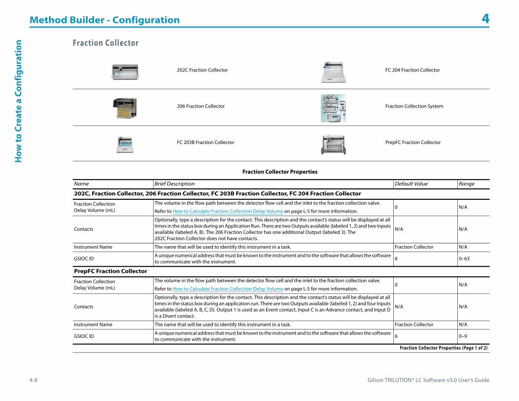
Method Builder - Configuration 4
4-8 Gilson TRILUTION® LC Software v3.0 User’s Guide
How
to C
reat
e a
Conf
igur
atio
n Fraction Collector
202C Fraction Collector FC 204 Fraction Collector
206 Fraction Collector Fraction Collection System
FC 203B Fraction Collector PrepFC Fraction Collector
Fraction Collector Properties
Name Brief Description Default Value Range
202C, Fraction Collector, 206 Fraction Collector, FC 203B Fraction Collector, FC 204 Fraction Collector
Fraction Collection Delay Volume (mL)
The volume in the flow path between the detector flow cell and the inlet to the fraction collection valve.
Refer to How to Calculate Fraction Collection Delay Volume on page L-5 for more information.0 N/A
Contacts
Optionally, type a description for the contact. This description and the contact’s status will be displayed at all times in the status box during an Application Run. There are two Outputs available (labeled 1, 2) and two Inputs available (labeled A, B). The 206 Fraction Collector has one additional Output (labeled 3). The 202C Fraction Collector does not have contacts.
N/A N/A
Instrument Name The name that will be used to identify this instrument in a task. Fraction Collector N/A
GSIOC ID A unique numerical address that must be known to the instrument and to the software that allows the software to communicate with the instrument. 6 0–63
PrepFC Fraction Collector
Fraction Collection Delay Volume (mL)
The volume in the flow path between the detector flow cell and the inlet to the fraction collection valve.
Refer to How to Calculate Fraction Collection Delay Volume on page L-5 for more information.0 N/A
Contacts
Optionally, type a description for the contact. This description and the contact’s status will be displayed at all times in the status box during an application run. There are two Outputs available (labeled 1, 2) and four Inputs available (labeled A, B, C, D). Output 1 is used as an Event contact, Input C is an Advance contact, and Input D is a Divert contact.
N/A N/A
Instrument Name The name that will be used to identify this instrument in a task. Fraction Collector N/A
GSIOC ID A unique numerical address that must be known to the instrument and to the software that allows the software to communicate with the instrument. 6 0–9
Fraction Collector Properties (Page 1 of 2)

Gilson TRILUTION® LC Software v3.0 User’s Guide 4-9
Method Builder - Configuration 4H
ow to Create a Configuration
Fraction Collection System (FCS)
The Fraction Collection System (FCS) is a group of instruments that are combined to allow fraction collection to multiple beds. An FCS consists of two or more fraction collectors and a VALVEMATE or VALVEMATE II. The configuration can only include one FCS.
How to Use an FCS1 Drag two fraction collectors into the workspace (for example, a 215 Liquid Handler to be used as a fraction collector and an FC 204
Fraction Collector) and set the properties.2 Drag a VALVEMATE or VALVEMATE II into the workspace and set the properties. The VALVEMATE or VALVEMATE II should be plumbed and
ready to go at this point.3 Drag a Fraction Collection System into the workspace.
a) On the Setup tab:• In the VALVEMATE field, click the arrow and then select the VALVEMATE or VALVEMATE II from the drop-down list.• In the Position field, click the arrow and then select the VALVEMATE or VALVEMATE II valve position from the drop-down list that
corresponds to the first fraction collector.Note: When using a 2-position valve on a VALVEMATE, choose 1 for position 0 or 2 for position 1.
b) On the General tab, do the following:• In the Instrument Name field, type a name for the FCS.
c) Repeat step 3 for additional fraction collectors.
Fraction Collection SystemFor more information, refer to How to Use an FCS.
Fraction Collector The fraction collectors in the configuration. N/A N/A
VALVEMATE The VALVEMATE or VALVEMATE II, selected from a drop-down list of VALVEMATEs and VALVEMATE IIs in the configuration, that the FCS will use. N/A N/A
Position The valve position on the VALVEMATE or VALVEMATE II. N/A1–10, depending on the valve
Instrument Name The name that will be used to identify this system in a task. Fraction Collection System N/A
Fraction Collector Properties (Continued)
Name Brief Description Default Value Range
Fraction Collector Properties (Page 2 of 2)

Method Builder - Configuration 4
4-10 Gilson TRILUTION® LC Software v3.0 User’s Guide
How
to C
reat
e a
Conf
igur
atio
n Injector
For a list of supplied tasks for the 819 Injection Module, refer to 819 Injection Module Tasks on page A-16.
For a list of supplied tasks for the 845Z Injection Module, refer to 845Z Injection Module Tasks on page A-17.
819 Injection Module 845Z Injection Module
Injector Properties
Name Brief Description Default Value Range
819 Injection Module, 845Z Injection Module
Injection Module Name The name that will be used to identify this injection module in a task. Injector N/A
GSIOC ID A unique numerical address that must be known to the injection module and to the software that allows the software to communicate with the injection module. 29 20–29
845Z Injection Module
Instrument Name The name that will be used to identify this injection module in a task. Injector N/A
GSIOC ID A unique numerical address that must be known to the injection module and to the software that allows the software to communicate with the injection module. 29 20–29
Injector Properties

Gilson TRILUTION® LC Software v3.0 User’s Guide 4-11
Method Builder - Configuration 4H
ow to Create a Configuration
Liquid Handler
215 Liquid Handler 215 Liquid Handler without Pump
231 XL Sample Injector 232 XL Sample Injector 233 XL Sample Injector
234 Autoinjector 235 Autoinjector
GX-271 Analytical Liquid Handler
GX-271 Liquid Handler without Pump GX-271 Prep Liquid Handler
GX-281 Analytical Liquid Handler
GX-281 Liquid Handler without Pump GX-281 Prep Liquid Handler

Method Builder - Configuration 4
4-12 Gilson TRILUTION® LC Software v3.0 User’s Guide
How
to C
reat
e a
Conf
igur
atio
n Liquid Handler Properties
Name Brief Description Default Value Range
215 Liquid Handler, 215 Liquid Handler without Pump
Z Arm Type (mm) This is the height of the Z-arm installed on the liquid handler. 125 mm Z-Arm 125 mm Z-Arm, 175 mm Z-Arm
Z Clamp Height (mm)This number corresponds to where the mounting clamp is on the vertical ruler on the installed Z-arm. 125 0–175
Z Safe Height (mm)The Z-height to which the instrument’s probe moves before moving in the X or Y direction. 122
Range provided on-screen; calculated based on Z Clamp Height and Z Arm Type.
Fraction Collection Delay Volume (mL)
The volume in the flow path between the detector flow cell and the inlet to the fraction collection valve.
Contact your local Gilson representative for help determining the value to enter for the system configuration.
For a configuration in which a channel on the Flexar SQ 300 MS Detector is the primary channel, the fraction collection delay volume must be calculated, using the following equation:
Fraction Collection Delay Volume = Fraction Collection Delay Volume (determined by your local Gilson representative) + [Time needed to align MS peaks with UV peaks * Mobile Phase Flow Rate]
0 N/A
ID A unique identifier to address syringes on the instrument. (215 Liquid Handler) A A
Syringe Name A unique name to address syringes on the instrument. (215 Liquid Handler) A N/A
Size (μL) The capacity of each installed syringe. (215 Liquid Handler) 1000 100, 250, 500, 1000, 5000, 10000, 25000
Reservoir NameA unique name used to identify the liquid that is flowing through the associated syringe. It is important for sample tracking. (215 Liquid Handler)
Reservoir N/A
Contacts
Optionally, type a description for the contact. This description and the contact’s status will be displayed at all times in the status box during an application run. There are four outputs available (labeled 1, 2, 3, 4), four inputs available (labeled A, B, C, D), and one 24V output.
N/A N/A
Instrument Name The name that will be used to identify this instrument in a task. Liquid Handler N/A
GSIOC IDA unique numerical address that must be known to the instrument and to the software that allows the software to communicate with the instrument.
22 20–29
Liquid Handler Properties (Page 1 of 5)

Gilson TRILUTION® LC Software v3.0 User’s Guide 4-13
Method Builder - Configuration 4H
ow to Create a Configuration
231 XL Sample Injector, 232 XL Sample Injector, 233 XL Sample Injector
Z Arm Type (mm) This is the height of the Z-arm installed on the liquid handler. 123 mm Z-Arm 56 mm Z-Arm, 123 mm Z-Arm,183 mm Z-Arm (232 and 233 XL Sample Injector)
Z Safe Height (mm) The Z-height to which the instrument’s probe moves before moving in the X or Y direction. -2 Range provided on-screen; calculated based on
Z Clamp Height and Z Arm Type.
Injection Valve Location The location of the installed injection valve. (233 XL Sample Injector) Right Left, Right
Fraction ValveThe type of fraction collection valve installed. The switching valve is built-in to the instrument. The low pressure valve is installed on the Z-arm. (233 XL Sample Injector)
Switching Switching, Low Pressure
Fraction Collection Delay Volume (mL)
The volume in the flow path between the detector flow cell and the inlet to the fraction collection valve.
Contact your local Gilson representative for help determining the value to enter for the system configuration.
0 N/A
ContactsOptionally, type a description for the contact. This description will be used to identify the contact in a Task. There are eight Outputs available (labeled 1–8) and five Inputs available (labeled 1–5).
N/A N/A
Instrument Name The name that will be used to identify this instrument in a task. Liquid Handler N/A
GSIOC IDA unique numerical address that must be known to the instrument and to the software that allows the software to communicate with the instrument.
10 0–31
234 Autoinjector
Z Safe Height (mm) The Z-height to which the instrument’s probe moves before moving in the X or Y direction. -2 -56 to 0
ID A unique identifier to address the syringe on the instrument. A A
Syringe Name A unique name to address the syringe on the instrument. A N/A
Size (μL) The capacity of the installed syringe. 500 100, 500
Contacts
Optionally, type a description for the contact. This description and the contact’s status will be displayed at all times in the status box during an application run. There are two outputs available (labeled 1, 2) and three inputs available (labeled A, B, C).
N/A N/A
Instrument Name The name that will be used to identify this instrument in a task. Liquid Handler N/A
GSIOC IDA unique numerical address that must be known to the instrument and to the software that allows the software to communicate with the instrument.
10 0–63
Liquid Handler Properties (Continued)
Name Brief Description Default Value Range
Liquid Handler Properties (Page 2 of 5)

Method Builder - Configuration 4
4-14 Gilson TRILUTION® LC Software v3.0 User’s Guide
How
to C
reat
e a
Conf
igur
atio
n
235 Autoinjector
ID A unique identifier to address the syringe on the instrument. A A
Syringe Name A unique name to address the syringe on the instrument. A N/A
Size (μL) The capacity of the installed syringe. 500 100, 250, 500, 1000
Pause instrument when door is opened. Cleared
Interior light is turned on. Selected
Contacts
Optionally, type a description for the contact. This description and the contact’s status will be displayed at all times in the status box during an application run. There are four outputs available (labeled 1, 2, 3, 4) and four inputs available (labeled A, B, C, D).
N/A N/A
Instrument Name The name that will be used to identify this instrument in a task. Liquid Handler N/A
GSIOC IDA unique numerical address that must be known to the instrument and to the software that allows the software to communicate with the instrument.
20 20-29
GX-271 Analytical Liquid Handler, GX-271 Liquid Handler without Pump, GX-271 Prep Liquid Handler
Probe Type (mm)If the stop pin was inserted in S1, select 56 mm Probe.If the stop pin was inserted in S2, select 125 mm Probe.If no stop pin was used, select 175 mm Probe.
125 mm Probe (GX-271 Analytical)175 mm Probe (GX-271 Prep) 56 mm Probe, 125 mm Probe, 175 mm Probe
Z Clamp Height (mm) This number corresponds to where the mounting clamp is on the vertical ruler on the installed Z-arm.
125 (GX-271 Analytical)175 (GX-271 Prep) 110–260
Z Safe Height (mm) The Z-height to which the instrument’s probe moves before moving in the X or Y direction.
122 (GX-271 Analytical)172 (GX-271 Prep) Calculated based on Z Clamp Height and Probe Type.
Rinse Park Location The rinse location to where the instrument home completes. Rear Front, Center, Rear
Transfer Tubing (mL) The size of the tubing being used from pump to probe. 1.1 (GX-271 Analytical)30 (GX-271 Prep)
0.5, 1.1, 5, 10.51.1, 5, 10.5, 30, 50 (GX-271 Prep)
Other Tubing (mL) When selected, the non-standard size of the tubing being used from pump to probe. (GX-271 Analytical and GX-271 Prep) 0 0–1000000
GX Direct Inject Valve Indicate the size of the injection valve installed. 1/16" (GX-271 Analytical)1/8" (GX-271 Prep) Not Installed, 1/8", 1/16"
Waste Indicate which port will be used for waste. (GX-271 Analytical and GX-271 Prep) Port 1 Port 1, Port 2, Port 3, Port 4, Port 5, Port 6
Ports 1–6Optionally, type a description of the solvent valve port. Five ports are available. One port is used for waste. (GX-271 Analytical and GX-271 Prep)
N/A N/A
Liquid Handler Properties (Continued)
Name Brief Description Default Value Range
Liquid Handler Properties (Page 3 of 5)

Gilson TRILUTION® LC Software v3.0 User’s Guide 4-15
Method Builder - Configuration 4H
ow to Create a Configuration
Fraction Collection Delay Volume (mL)
The volume in the flow path between the detector flow cell and the inlet to the fraction collection valve.
Contact your local Gilson representative for help determining the value to enter for the system configuration.
For a configuration in which a channel on the Flexar SQ 300 MS Detector is the primary channel, the fraction collection delay volume must be calculated, using the following equation:
Fraction Collection Delay Volume = Fraction Collection Delay Volume (determined by your local Gilson representative) + [Time needed to align MS peaks with UV peaks * Mobile Phase Flow Rate]
0 N/A
Output
Optionally, type a description for the contact. This description and the contact’s status will be displayed at all times in the status box during an application run. There are two outputs available (labeled 1, 2).
Additionally, indicate whether the contact should open, close, or remain in the same state on error. The default is No Change.
N/A N/A
24V Output
Optionally, type a description for the contact. This description and the contact’s status will be displayed at all times in the status box during an application run. There are two 24V outputs available (labeled 1, 2).
Additionally, indicate whether the contact should open, close, or remain in the same state on error. The default is Open.
N/A N/A
InputOptionally, type a description for the contact. This description and the contact’s status will be displayed at all times in the status box during an application run. There are two inputs available (labeled A, B).
N/A N/A
Solenoid Optionally, type a description for the solenoid. There are two solenoids available (labeled 1, 2). N/A N/A
Instrument Name The name that will be used to identify this instrument in a task. Liquid Handler N/A
Instrument Serial Number The serial number of the instrument. N/A N/A
Pump Serial Number The serial number of the GX Solvent System. (GX-271 Analytical and GX-271 Prep) N/A N/A
Injection Module Serial Number The serial number of the injection module. N/A N/A
GX-281 Analytical Liquid Handler, GX-281 Liquid Handler without Pump, GX-281 Prep Liquid Handler
Probe Type (mm) This is the Z travel height.125 mm Probe (GX-281 Analytical)175 mm Probe (GX-281 Prep, GX-281 without Pump)
125 mm Probe, 175 mm Probe, 210 mm Probe
Z Clamp Height (mm) This number corresponds to where the mounting clamp is on the vertical ruler on the installed Z-arm.
125 (GX-281 Analytical)175 (GX-281 Prep, GX-281 without Pump)
95–300
Z Safe Height (mm) The Z-height to which the instrument’s probe moves before moving in the X or Y direction.
122 (GX-281 Analytical)172 (GX-281 Prep, GX-281 without Pump)
0-175Calculated based on Z Clamp Height and Probe Type.
Liquid Handler Properties (Continued)
Name Brief Description Default Value Range
Liquid Handler Properties (Page 4 of 5)

Method Builder - Configuration 4
4-16 Gilson TRILUTION® LC Software v3.0 User’s Guide
How
to C
reat
e a
Conf
igur
atio
n
Rinse Park Location The rinse location to where the instrument home completes. Left 1 Left 1, Left 2, Left 3, Right 1, Right 2, Right 3
Transfer Tubing (mL) The size of the tubing being used from pump to probe. 1.1 (GX-281 Analytical)30 (GX-281 Prep)
0.5, 1.1, 3, 5, 10.51.1, 3, 5, 10.5, 30, 50
Other Tubing (mL) When selected, the non-standard size of the tubing being used from pump to probe. (GX-281 Analytical and GX-281 Prep) 0 0–1000000
Left GX Direct Inject Valve Indicate the size of the injection valve installed in the left position. 1/16" (GX-281 Analytical)1/8" (GX-281 Prep, GX-281 without Pump)
Not Installed, 1/8", 1/16"Right GX Direct Inject Valve Indicate the size of the injection valve installed in the right position.
Z Injection Valve Indicate whether (checked) or not (cleared) a Z Injection Valve is installed.
Cleared N/A
Waste Indicate which port will be used for waste. (GX-281 Analytical and GX-281 Prep)
Port 1 Port 1, Port 2, Port 3, Port 4, Port 5, Port 6
Ports 1–6Optionally, type a description of the solvent valve port. Five ports are available. One port is used for waste. (GX-281 Analytical and GX-281 Prep) N/A N/A
Fraction Collection Delay Volume (mL)
The volume in the flow path between the detector flow cell and the inlet to the fraction collection valve.
Contact your local Gilson representative for help determining the value to enter for the system configuration.
For a configuration in which a channel on the Flexar SQ 300 MS Detector is the primary channel, the fraction collection delay volume must be calculated, using the following equation:
Fraction Collection Delay Volume = Fraction Collection Delay Volume (determined by your local Gilson representative) + [Time needed to align MS peaks with UV peaks * Mobile Phase Flow Rate]
0 N/A
Output
Optionally, type a description for the contact. This description and the contact’s status will be displayed at all times in the status box during an application run. There are four outputs available (labeled 1, 2, 3, 4).
Additionally, indicate whether the contact should open, close, or remain in the same state on error. The default is No Change.
N/A N/A
24V Output
Optionally, type a description for the contact. This description and the contact’s status will be displayed at all times in the status box during an application run. There are four 24V outputs available (1, 2, 3, and 4).
Additionally, indicate whether the contact should open, close, or remain in the same state on error. The default is Open.
N/A N/A
InputOptionally, type a description for the contact. This description and the contact’s status will be displayed at all times in the status box during an application run. There are four inputs available (labeled A, B, C, D).
N/A N/A
Instrument Name The name that will be used to identify this instrument in a task. Liquid Handler N/A
GSIOC IDA unique numerical address that must be known to the instrument and to the software that allows the software to communicate with the instrument.
25 20–29
Liquid Handler Properties (Continued)
Name Brief Description Default Value Range
Liquid Handler Properties (Page 5 of 5)
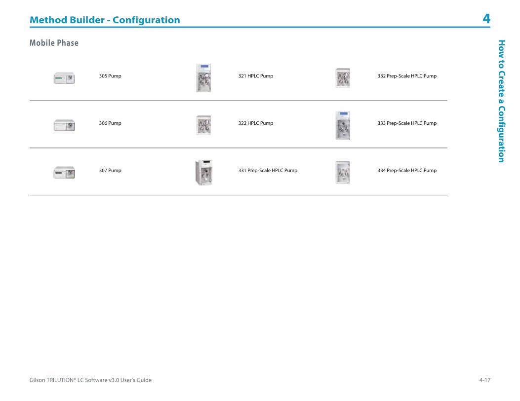
Gilson TRILUTION® LC Software v3.0 User’s Guide 4-17
Method Builder - Configuration 4H
ow to Create a Configuration
Mobile Phase
305 Pump 321 HPLC Pump 332 Prep-Scale HPLC Pump
306 Pump 322 HPLC Pump 333 Prep-Scale HPLC Pump
307 Pump 331 Prep-Scale HPLC Pump 334 Prep-Scale HPLC Pump
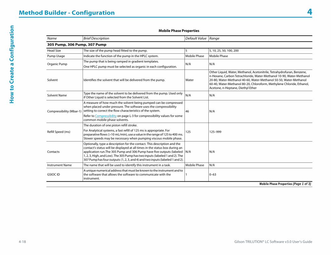
Method Builder - Configuration 4
4-18 Gilson TRILUTION® LC Software v3.0 User’s Guide
How
to C
reat
e a
Conf
igur
atio
n
Mobile Phase Properties
Name Brief Description Default Value Range
305 Pump, 306 Pump, 307 Pump
Head Size The size of the pump head fitted to the pump. 5 5, 10, 25, 50, 100, 200
Pump Usage Indicate the function of the pump in the HPLC system. Mobile Phase Mobile Phase
Organic PumpThe pump that is being ramped in gradient templates.
One HPLC pump must be selected as organic in each configuration.N/A N/A
Solvent Identifies the solvent that will be delivered from the pump. Water
Other Liquid, Water, Methanol, Acetonitrile, Tetrahydrofuran, Benzene, n-Hexane, Carbon Tetrachloride, Water-Methanol 10-90, Water-Methanol 20-80, Water-Methanol 40-60, Water-Methanol 50-50, Water-Methanol 60-40, Water-Methanol 80-20, Chloroform, Methylene Chloride, Ethanol, Acetone, n-Heptane, Diethyl Ether
Solvent Name Type the name of the solvent to be delivered from the pump. Used only if Other Liquid is selected from the Solvent List. N/A N/A
Compressibility (Mbar-1)
A measure of how much the solvent being pumped can be compressed when placed under pressure. The software uses the compressibility setting to correct the flow characteristics of the system.
Refer to Compressibility on page L-3 for compressibility values for some common mobile phase solvents.
46 N/A
Refill Speed (ms)
The duration of one piston refill stroke.
For Analytical systems, a fast refill of 125 ms is appropriate. For preparative flows (>10 mL/min), use a value in the range of 125 to 400 ms. Slower speeds may be necessary when pumping viscous mobile phase.
125 125–999
Contacts
Optionally, type a description for the contact. This description and the contact’s status will be displayed at all times in the status box during an application run.The 305 Pump and 306 Pump have five outputs (labeled 1, 2, 3, High, and Low). The 305 Pump has two inputs (labeled 1 and 2). The 307 Pump has four outputs (1, 2, 3, and 4) and two inputs (labeled 1 and 2).
N/A N/A
Instrument Name The name that will be used to identify this instrument in a task. Mobile Phase N/A
GSIOC IDA unique numerical address that must be known to the instrument and to the software that allows the software to communicate with the instrument.
1 0–63
Mobile Phase Properties (Page 1 of 3)
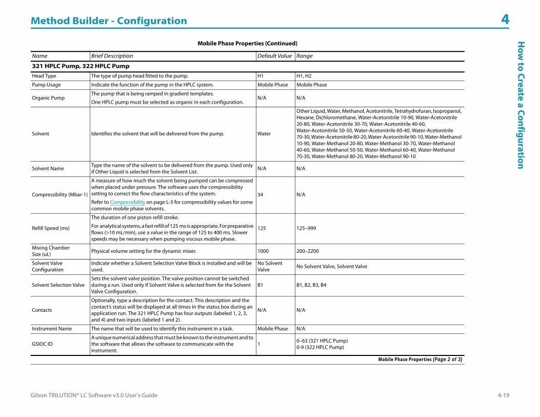
Gilson TRILUTION® LC Software v3.0 User’s Guide 4-19
Method Builder - Configuration 4H
ow to Create a Configuration
321 HPLC Pump, 322 HPLC Pump
Head Type The type of pump head fitted to the pump. H1 H1, H2
Pump Usage Indicate the function of the pump in the HPLC system. Mobile Phase Mobile Phase
Organic PumpThe pump that is being ramped in gradient templates.
One HPLC pump must be selected as organic in each configuration.N/A N/A
Solvent Identifies the solvent that will be delivered from the pump. Water
Other Liquid, Water, Methanol, Acetonitrile, Tetrahydrofuran, Isopropanol, Hexane, Dichloromethane, Water-Acetonitrile 10-90, Water-Acetonitrile 20-80, Water-Acetonitrile 30-70, Water-Acetonitrile 40-60, Water-Acetonitrile 50-50, Water-Acetonitrile 60-40, Water-Acetonitrile 70-30, Water-Acetonitrile 80-20, Water-Acetonitrile 90-10, Water-Methanol 10-90, Water-Methanol 20-80, Water-Methanol 30-70, Water-Methanol 40-60, Water-Methanol 50-50, Water-Methanol 60-40, Water-Methanol 70-30, Water-Methanol 80-20, Water-Methanol 90-10
Solvent Name Type the name of the solvent to be delivered from the pump. Used only if Other Liquid is selected from the Solvent List.
N/A N/A
Compressibility (Mbar-1)
A measure of how much the solvent being pumped can be compressed when placed under pressure. The software uses the compressibility setting to correct the flow characteristics of the system.
Refer to Compressibility on page L-3 for compressibility values for some common mobile phase solvents.
34 N/A
Refill Speed (ms)
The duration of one piston refill stroke.
For analytical systems, a fast refill of 125 ms is appropriate. For preparative flows (>10 mL/min), use a value in the range of 125 to 400 ms. Slower speeds may be necessary when pumping viscous mobile phase.
125 125–999
Mixing Chamber Size (uL) Physical volume setting for the dynamic mixer. 1000 200–2200
Solvent Valve Configuration
Indicate whether a Solvent Selection Valve Block is installed and will be used.
No Solvent Valve No Solvent Valve, Solvent Valve
Solvent Selection ValveSets the solvent valve position. The valve position cannot be switched during a run. Used only if Solvent Valve is selected from for the Solvent Valve Configuration.
B1 B1, B2, B3, B4
Contacts
Optionally, type a description for the contact. This description and the contact’s status will be displayed at all times in the status box during an application run. The 321 HPLC Pump has four outputs (labeled 1, 2, 3, and 4) and two inputs (labeled 1 and 2).
N/A N/A
Instrument Name The name that will be used to identify this instrument in a task. Mobile Phase N/A
GSIOC IDA unique numerical address that must be known to the instrument and to the software that allows the software to communicate with the instrument.
1 0–63 (321 HPLC Pump)0-9 (322 HPLC Pump)
Mobile Phase Properties (Continued)
Name Brief Description Default Value Range
Mobile Phase Properties (Page 2 of 3)

Method Builder - Configuration 4
4-20 Gilson TRILUTION® LC Software v3.0 User’s Guide
How
to C
reat
e a
Conf
igur
atio
n
331 Prep-Scale HPLC Pump, 332 Prep-Scale HPLC Pump, 333 Prep-Scale HPLC Pump, 334 Prep-Scale HPLC Pump
Head Type The type of pump head fitted to the pump. H2H3
H2 (331 and 332 Prep-Scale HPLC Pump)H3 (333 and 334 Prep-Scale HPLC Pump)
Pump Usage Indicate the function of the pump in the HPLC system. Mobile Phase Mobile Phase
Organic PumpThe pump that is being ramped in gradient templates.
One HPLC pump must be selected as organic in each configuration.N/A N/A
Solvent Valve Configuration
Indicate whether a Solvent Selection Valve Block is installed and will be used.
No Solvent Valve No Solvent Valve, Solvent Valve
Solvent Selection ValveSets the solvent valve position. The valve position cannot be switched during a run. Used only if Solvent Valve is selected from for the Solvent Valve Configuration.
1 1, 2, 3, 4
Solvent Identifies the solvent that will be delivered from the pump. Water
Other Liquid, Water, Methanol, Acetonitrile, Tetrahydrofuran, Isopropanol, Hexane, Dichloromethane, Water-Acetonitrile 10-90, Water-Acetonitrile 20-80, Water-Acetonitrile 30-70, Water-Acetonitrile 40-60, Water-Acetonitrile 50-50, Water-Acetonitrile 60-40, Water-Acetonitrile 70-30, Water-Acetonitrile 80-20, Water-Acetonitrile 90-10, Water-Methanol 10-90, Water-Methanol 20-80, Water-Methanol 30-70, Water-Methanol 40-60, Water-Methanol 50-50, Water-Methanol 60-40, Water-Methanol 70-30, Water-Methanol 80-20, Water-Methanol 90-10
Solvent Name Type the name of the solvent to be delivered from the pump. Used only if Other Liquid is selected from the Solvent List. N/A N/A
Compressibility (Mbar-1)
A measure of how much the solvent being pumped can be compressed when placed under pressure. The software uses the compressibility setting to correct the flow characteristics of the system.
Refer to Compressibility on page L-3 for compressibility values for some common mobile phase solvents.
34 N/A
Mixing Chamber Size (uL)
Physical volume setting for the dynamic mixer. (331 and 332 Prep-Scale HPLC Pump) 1000 200–2200
Contacts
Optionally, type a description for the contact. This description and the contact’s status will be displayed at all times in the status box during an application run. The 331 and 333 Prep-Scale HPLC Pumps have four outputs (labeled 1, 2, 3, and 4) and two inputs (labeled 1 and 2).
N/A N/A
Instrument Name The name that will be used to identify this instrument in a task. Mobile Phase N/A
GSIOC IDA unique numerical address that must be known to the instrument and to the software that allows the software to communicate with the instrument.
12
0–63 (331 and 333 Prep-Scale HPLC Pump)0-9 (332 and 334 Prep-Scale HPLC Pump)
Mobile Phase Properties (Continued)
Name Brief Description Default Value Range
Mobile Phase Properties (Page 3 of 3)
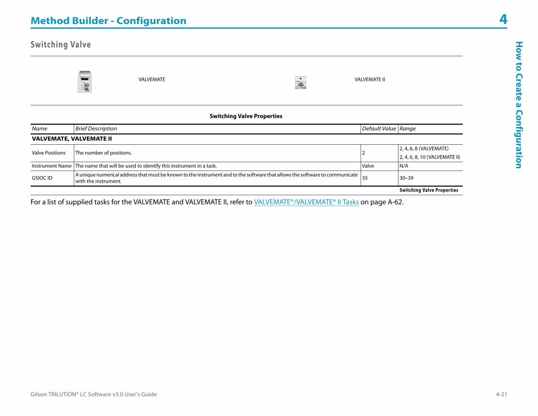
Gilson TRILUTION® LC Software v3.0 User’s Guide 4-21
Method Builder - Configuration 4H
ow to Create a Configuration
Switching Valve
For a list of supplied tasks for the VALVEMATE and VALVEMATE II, refer to VALVEMATE®/VALVEMATE® II Tasks on page A-62.
VALVEMATE VALVEMATE II
Switching Valve Properties
Name Brief Description Default Value Range
VALVEMATE, VALVEMATE II
Valve Positions The number of positions. 22, 4, 6, 8 (VALVEMATE)
2, 4, 6, 8, 10 (VALVEMATE II)
Instrument Name The name that will be used to identify this instrument in a task. Valve N/A
GSIOC ID A unique numerical address that must be known to the instrument and to the software that allows the software to communicate with the instrument. 35 30–39
Switching Valve Properties

Method Builder - Configuration 4
4-22 Gilson TRILUTION® LC Software v3.0 User’s Guide
How
to C
reat
e a
Conf
igur
atio
n Communication
For a list of supplied tasks for the 506C System Interface, refer to 506C System Interface Tasks on page A-63.
506C System Interface 606 GSIOC to RS-232 Converter
Communication Properties
Name Brief Description Default Value Range
506C System Interface
Data Channels
Optionally, type a unique description for each data channel. This description and the data channel’s signal will be displayed in the status box while Data are being collected during an application run if the Use check box is selected for that data channel. There are four data channels available (labeled A, B, C, D).
The maximum number of channels per configuration that can be used is eight.
506C Channel A N/A
Data Rate (points/sec) The number of data points collected per second for the channel. There are four data channels available (labeled A, B, C, D). 20 1–80
Units
The user unit that corresponds to the mV value indicated and the label for those units.
Data are scaled, plotted, and analyzed according to selected these units. All calculations (i.e., heights and areas) are reported according to these units. Units are shown on the graph axis (while running and in reports). Multiple graph axes are displayed if different user units are set for different data channels. A symbol is displayed on the graph axis to indicate which data channel is using that axis.
1 mV = 1 mV N/A
Contacts Optionally, type a description for the contacts. This description and the contacts’ status will be displayed at all times in the status box during an application run. There are six outputs (labeled 1–6), four inputs (labeled A, B, C, D), and four analog inputs (labeled A, B, C, D). N/A N/A
Instrument Name The name that will be used to identify this instrument in a task. Contact N/A
GSIOC ID A unique numerical address that must be known to the instrument and to the software that allows the software to communicate with the instrument. 63 0–63
606 GSIOC to RS-232 Converter
Baud Rate The speed at which information is sent. 19200
75, 110, 150, 300, 600, 1200, 1800, 2000, 2400, 4800, 9600, 19200, 38400
Parity The number of 1s in the group of bits. Even Even, Odd, None, M(1), S(0)
Bits per Character The number of binary digits that constitutes a character. 7 5, 6, 7, 8
Stop Bits The number of bits to be transmitted after each character. 1 1, 2
Handshake The device with which information is being transmitted or exchanged. NoneHardware, Software, Both, None
Instrument Name The name that will be used to identify this instrument in a task. Communication N/A
GSIOC ID A unique numerical address that must be known to the instrument and to the software that allows the software to communicate to the instrument. 61 0–63
Communication Properties

Gilson TRILUTION® LC Software v3.0 User’s Guide 4-23
Method Builder - Configuration 4H
ow to Create a Configuration
Syringe Pump
307 Make Up Pump 402 Pump Dual
402 Pump Single 402 Pump Dual with Tee
Virtual Pumping System
Syringe Pump Properties
Name Brief Description Default Value Range
307 Make Up Pump
Head Size The size of the pump head fitted to the pump. 5 5, 10, 25, 50, 100, 200
Pump Usage Indicate the function of the pump in the system. Make Up Make Up
Solvent Identifies the solvent that will be delivered from the pump. Water
Other Liquid, Water, Methanol, Acetonitrile, Tetrahydrofuran, Benzene, n-Hexane, Carbon Tetrachloride, Water-Methanol 10-90, Water-Methanol 20-80, Water-Methanol 40-60, Water-Methanol 50-50, Water-Methanol 60-40, Water-Methanol 80-20, Chloroform, Methylene Chloride, Ethanol, Acetone, n-Heptane, Diethyl Ether
Solvent Name Type the name of the solvent to be delivered from the pump. Used only if Other Liquid is selected from the Solvent List. N/A N/A
Compressibility (Mbar-1)
A measure of how much the solvent being pumped can be compressed when placed under pressure. The software uses the compressibility setting to correct the flow characteristics of the system.
Refer to Compressibility on page L-3 for compressibility values for some common solvents.
46 N/A
Refill Speed (ms) The duration of one piston refill stroke. 125 125–999
ContactsOptionally, type a description for the contact. This description and the contact’s status will be displayed at all times in the status box during an application run. The 307 Make Up Pump has four outputs (1, 2, 3, 4) and two inputs (labeled 1, 2).
N/A N/A
Instrument Name The name that will be used to identify this instrument in a task. Make Up Pump N/A
GSIOC ID A unique numerical address that must be known to the instrument and to the software that allows the software to communicate with the instrument.
1 0–63
Syringe Pump Properties (Page 1 of 2)
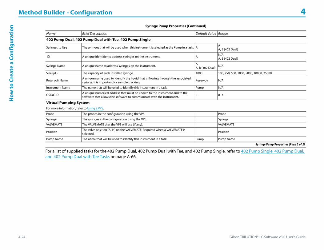
Method Builder - Configuration 4
4-24 Gilson TRILUTION® LC Software v3.0 User’s Guide
How
to C
reat
e a
Conf
igur
atio
n
For a list of supplied tasks for the 402 Pump Dual, 402 Pump Dual with Tee, and 402 Pump Single, refer to 402 Pump Single, 402 Pump Dual, and 402 Pump Dual with Tee Tasks on page A-66.
402 Pump Dual, 402 Pump Dual with Tee, 402 Pump Single
Syringes to Use The syringes that will be used when this instrument is selected as the Pump in a task. A AA, B (402 Dual)
ID A unique identifier to address syringes on the instrument. A N/AA, B (402 Dual)
Syringe Name A unique name to address syringes on the instrument. AA, B (402 Dual) N/A
Size (μL) The capacity of each installed syringe. 1000 100, 250, 500, 1000, 5000, 10000, 25000
Reservoir NameA unique name used to identify the liquid that is flowing through the associated syringe. It is important for sample tracking. Reservoir N/A
Instrument Name The name that will be used to identify this instrument in a task. Pump N/A
GSIOC ID A unique numerical address that must be known to the instrument and to the software that allows the software to communicate with the instrument.
0 0–31
Virtual Pumping SystemFor more information, refer to Using a VPS.
Probe The probes in the configuration using the VPS. Probe
Syringe The syringes in the configuration using the VPS. Syringe
VALVEMATE The VALVEMATE that the VPS will use (if any). VALVEMATE
Position The valve position (A–H) on the VALVEMATE. Required when a VALVEMATE is selected. Position
Pump Name The name that will be used to identify this instrument in a task. Pump Pump Name
Syringe Pump Properties (Continued)
Name Brief Description Default Value Range
Syringe Pump Properties (Page 2 of 2)

Gilson TRILUTION® LC Software v3.0 User’s Guide 4-25
Method Builder - Configuration 4H
ow to Create a Configuration
Virtual Pumping System (VPS)
The Virtual Pumping System (VPS) is a group of instruments that are combined to perform as a pumping system. A VPS consists of a probe from a liquid handler and syringes. Optionally, a VALVEMATE may be included to provide additional fluid paths. The configuration can include one or more VPS.
Using a VPS
For a system using multiple reservoir solutions:
1 Drag and drop a liquid handler with an installed single syringe pump into the workspace (for example, 215 Liquid Handler) and set the properties.
2 Drag and drop a VALVEMATE or VALVEMATE II into the workspace and set the properties. Your VALVEMATE or VALVEMATE II should be plumbed and ready to go at this point.
3 Drag and drop a Virtual Pumping System into the workspace.a) In the VALVEMATE field, click the arrow and then select the VALVEMATE or VALVEMATE II from the drop-down list.b) In the Position field, click the arrow and then select the VALVEMATE or VALVEMATE II valve position from the drop-down list that
corresponds to the first reservoir solution.c) In the Pump Name field, type a name for the first VPS. This is a good place to reference the first reservoir solution. This name will be used
to identify the VPS in a task.4 Repeat step 3 for additional reservoirs.
Single-Probe, Multiple-Syringe Configuration1 Drag and drop a liquid handler into the workspace and set the properties.2 Drag and drop a VALVEMATE into the workspace and set the properties. Your VALVEMATE or VALVEMATE II should be plumbed and ready to
go at this point.3 Drag and drop the pumps into the workspace and set the properties. Set a unique GSIOC ID for each.4 Drag and drop a Virtual Pumping System into the workspace.
a) Click on a Syringe Name and then click the up or down arrow to associate the syringe with a probe.b) In the VALVEMATE field, click the arrow and then select the VALVEMATE or VALVEMATE II from the drop-down list.c) In the Position field, click the arrow and then select the VALVEMATE or VALVEMATE II valve position from the drop-down list that
corresponds to the syringe.d) In the Pump Name field, type a name for the VPS. This name will be used to identify the VPS in a Task.
5 Repeat step 4 for each additional syringe.

Method Builder - Configuration 4
4-26 Gilson TRILUTION® LC Software v3.0 User’s Guide
Mod
ify a
Con
figur
atio
n Modify a ConfigurationA configuration can be modified by doing any of the following:• adding new instruments to an existing configuration• removing instruments from an existing configuration• modifying the instrument properties of the instruments in a configuration• browsing for an existing configuration to replace the current configuration
Remove an Instrument from a ConfigurationTo remove an instrument from a configuration, do either of the following:• Right-click on an instrument in the workspace and then select Remove.• Select an instrument in the workspace and then press the DELETE key.

Gilson TRILUTION® LC Software v3.0 User’s Guide 5-1
Method Builder - Bed Layout 5
A bed layout serves as one of the building blocks of a method and consists of:
• a template
• footprints
• racks
• wells
To create a bed layout, refer to How to Create a Bed Layout.

Method Builder - Bed Layout 5
5-2 Gilson TRILUTION® LC Software v3.0 User’s Guide
Bed
Layo
ut T
abW
indo
w Bed Layout Tab WindowThe Bed Layout tab window in the Method Builder is a graphical interface used to create a bed layout.
The Bed Layout tab window includes:• Zone Management• Zone Numbering Pattern• Workspace• Color Management
For information on how to create a bed layout, refer to How to Create a Bed Layout.
For information on how to modify a bed layout, refer to How to Modify a Bed Layout.
Zone ManagementUse Zone Management to add, modify, or delete zones, and to select zones for inactive and active wells.
Zone Numbering PatternAllows for selecting how blocks of wells will be numbered.
To select a pattern for numbering the wells:
1 Click the icon for the numbering pattern.2 Click the icon for the starting corner.
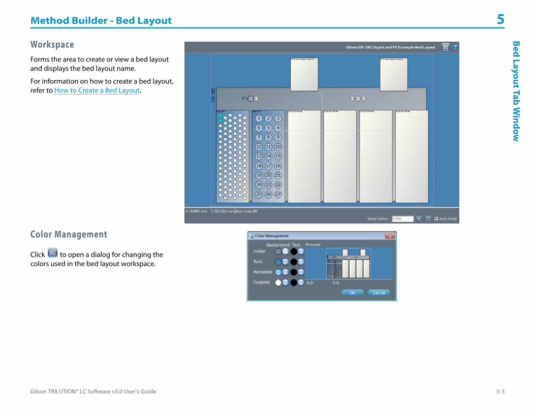
Gilson TRILUTION® LC Software v3.0 User’s Guide 5-3
Method Builder - Bed Layout 5Bed
Layout TabW
indow
WorkspaceForms the area to create or view a bed layout and displays the bed layout name.
For information on how to create a bed layout, refer to How to Create a Bed Layout.
Color Management
Click to open a dialog for changing the colors used in the bed layout workspace.

Method Builder - Bed Layout 5
5-4 Gilson TRILUTION® LC Software v3.0 User’s Guide
How
to C
reat
e a
Bed
Layo
ut How to Create a Bed LayoutIn the Method Builder, first create a configuration (refer to How to Create a Configuration on page 4-4), and then select the Bed Layout tab.
Optionally, right-click on the bed layout name in the Configured Instruments panel and then select Rename Bed Layout to rename the bed layout.
Select a TemplateDo one of the following.• To use the displayed template, continue to Add a Rack/Rinse Station/Injection Port.• Right-click on the bed layout name in the Configured Instruments panel, select New Bed Layout, and then select a bed layout template.
Templates are filtered for the associated instrument. Click OK. The window is refreshed to display the new template.
Define a ZoneTo define a Zone:
1 Under Zone Management, click Add Zone.2 Type a unique name, select colors, and select the starting number.
• Name: It is possible to create multiple zones, but each must have a unique name.• Starting: The first number that will be used when numbering wells in the zone.• Active Text Color: The color that is used (either black or white, depending on the active zone
color) for the numbers of the wells when the zone is active.• Active Zone Color: The color used for the wells in the zone when it is active. As new zones are added, the Active Zone Color
automatically increments. The zone becomes active when it is selected from the Zone drop-down menu. Only one zone can be active at a time. Refer to the Sample in the dialog to see the Active Text Color on the Active Zone Color.
• Inactive Text Color: The color that is used for the numbers of the wells when the zone is inactive.• Inactive Zone Color: The color used for the wells in the zone when it is inactive. The zone becomes inactive when another zone is
selected from the Zone drop-down menu. Multiple zones can be inactive at one time. The default Inactive Text Color is Black. The default Inactive Zone Color is light blue. Refer to the sample in the dialog to see the Inactive Text Color on the Inactive Zone Color.
3 Click OK. The zone is listed under Zone Management.
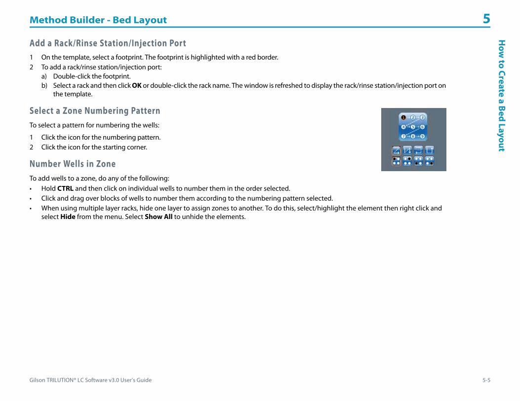
Gilson TRILUTION® LC Software v3.0 User’s Guide 5-5
Method Builder - Bed Layout 5H
ow to Create a Bed
Layout
Add a Rack/Rinse Station/Injection Port1 On the template, select a footprint. The footprint is highlighted with a red border.2 To add a rack/rinse station/injection port:
a) Double-click the footprint.b) Select a rack and then click OK or double-click the rack name. The window is refreshed to display the rack/rinse station/injection port on
the template.
Select a Zone Numbering PatternTo select a pattern for numbering the wells:
1 Click the icon for the numbering pattern.2 Click the icon for the starting corner.
Number Wells in ZoneTo add wells to a zone, do any of the following:• Hold CTRL and then click on individual wells to number them in the order selected.• Click and drag over blocks of wells to number them according to the numbering pattern selected.• When using multiple layer racks, hide one layer to assign zones to another. To do this, select/highlight the element then right click and
select Hide from the menu. Select Show All to unhide the elements.

Method Builder - Bed Layout 5
5-6 Gilson TRILUTION® LC Software v3.0 User’s Guide
How
to M
odify
a B
edLa
yout How to Modify a Bed Layout
Modify a bed layout by doing any of the following:• adding new racks, wells, or zones to the template• deleting zones or deleting racks from the workspace• changing the zone numbering pattern• replacing racks in the workspace• adding wells to zones• clearing wells from zones
To modify a bed layout:
1 Open the method and then select the Bed Layout tab.2 Right-click on the bed layout name in the Configured Instruments panel, select Browse Bed Layout, and then select an existing bed layout
to replace the current bed layout in the method.
Or
1 Open the method, and then select the Bed Layout tab.2 Do any of the following:
a) Add new racks, wells, or zones to the template; refer to How to Create a Bed Layout.Note: When modifying a bed layout, you may wish to select wells without adding them to a zone. To do this, right-click in the Zone Management panel, select Deselect All Zones, and then select the wells.
b) Delete racks from the workspace:1) Click to select/highlight the rack.2) Right-click and then select Delete or press the DELETE key.
c) Delete wells from all zones or from the active zone:1) Select the wells.2) Right-click and then select either Clear Selected Wells from Active Zone or Clear Selected Wells from All Zones.
d) Clear all wells from all zones or clear wells from the active zone:1) Click to select any element.2) Right-click and then select either Clear All Zones or Clear Active Zone.
e) Delete zones:1) Select the zone to be deleted.2) Click Delete or press the DELETE key.
f ) Change the colors. Double-click the zone name to modify.g) Change the zone numbering pattern; refer to Select a Zone Numbering Pattern.
Gilson TRILUTION® LC Software v3.0 User’s Guide 6-1
Method Builder - Control 6
The Method Builder - Control tab is where the sequence of tasks to execute and the gradient or isocratic condition are specified for the method.
To begin creating a method, select Method from the Liquid Chromatography menu.
For information about how to create a method, refer to How to Create a Method on page 3-6.
Key concepts to understand about the Method Builder - Control tab are:
• How to Create Gradient or Isocratic Conditions
• How to Simulate Fraction Collection by Slope or Level

Method Builder - Control 6
6-2 Gilson TRILUTION® LC Software v3.0 User’s Guide
Cont
rol T
abW
indo
w Control Tab WindowThe Control tab window in the Method Builder is a graphical interface used to organize the tasks used in a method.
The Control tab window includes:• Tasks Palette• Workspace Tab• Error Handling Tab
For information about how to create a method, refer to How to Create a Method on page 3-6.
Tasks PaletteThe Tasks palette displays sorted tasks that can be added to the control. Specify task conditions for controlling instruments.
One default group (Auxiliary) exists for every method. Auxiliary tasks are not specific to any instrument.
Mobile phase tasks are listed under Mobile Phase and then under the instrument name given to the pump.
All other tasks are listed alphanumerically under the instrument name.
For descriptions of Gilson-supplied tasks, refer to Appendix A, List of Tasks.
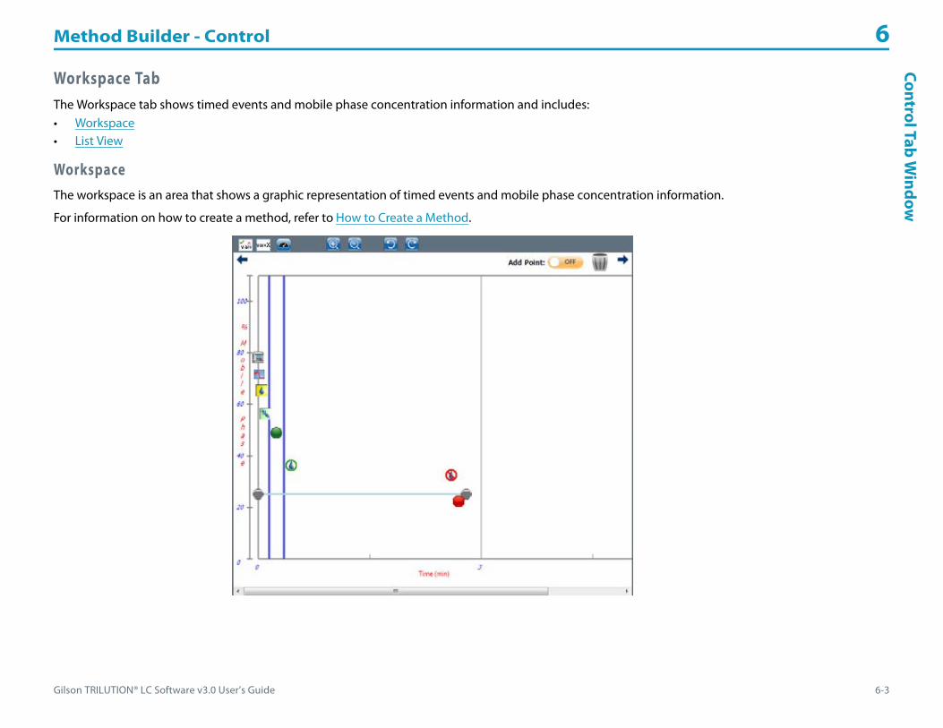
Gilson TRILUTION® LC Software v3.0 User’s Guide 6-3
Method Builder - Control 6Control Tab
Window
Workspace TabThe Workspace tab shows timed events and mobile phase concentration information and includes:• Workspace• List View
WorkspaceThe workspace is an area that shows a graphic representation of timed events and mobile phase concentration information.
For information on how to create a method, refer to How to Create a Method.
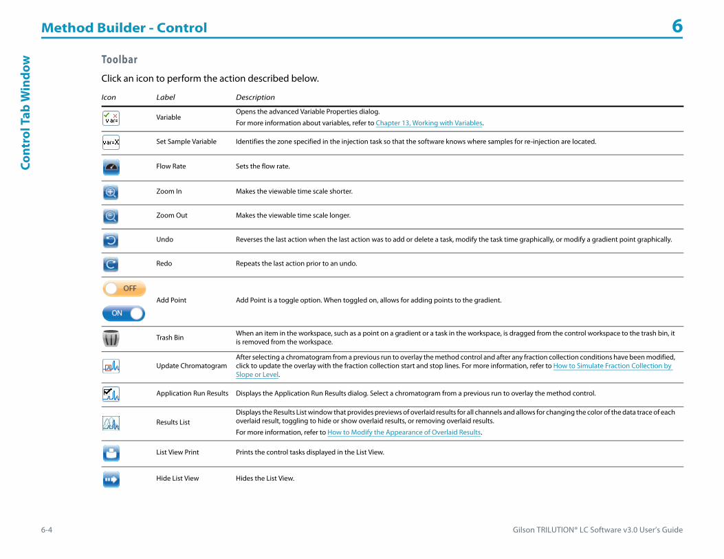
Method Builder - Control 6
6-4 Gilson TRILUTION® LC Software v3.0 User’s Guide
Cont
rol T
abW
indo
w Toolbar
Click an icon to perform the action described below.
Icon Label Description
VariableOpens the advanced Variable Properties dialog.
For more information about variables, refer to Chapter 13, Working with Variables.
Set Sample Variable Identifies the zone specified in the injection task so that the software knows where samples for re-injection are located.
Flow Rate Sets the flow rate.
Zoom In Makes the viewable time scale shorter.
Zoom Out Makes the viewable time scale longer.
Undo Reverses the last action when the last action was to add or delete a task, modify the task time graphically, or modify a gradient point graphically.
Redo Repeats the last action prior to an undo.
Add Point Add Point is a toggle option. When toggled on, allows for adding points to the gradient.
Trash Bin When an item in the workspace, such as a point on a gradient or a task in the workspace, is dragged from the control workspace to the trash bin, it is removed from the workspace.
Update ChromatogramAfter selecting a chromatogram from a previous run to overlay the method control and after any fraction collection conditions have been modified, click to update the overlay with the fraction collection start and stop lines. For more information, refer to How to Simulate Fraction Collection by Slope or Level.
Application Run Results Displays the Application Run Results dialog. Select a chromatogram from a previous run to overlay the method control.
Results ListDisplays the Results List window that provides previews of overlaid results for all channels and allows for changing the color of the data trace of each overlaid result, toggling to hide or show overlaid results, or removing overlaid results.
For more information, refer to How to Modify the Appearance of Overlaid Results.
List View Print Prints the control tasks displayed in the List View.
Hide List View Hides the List View.
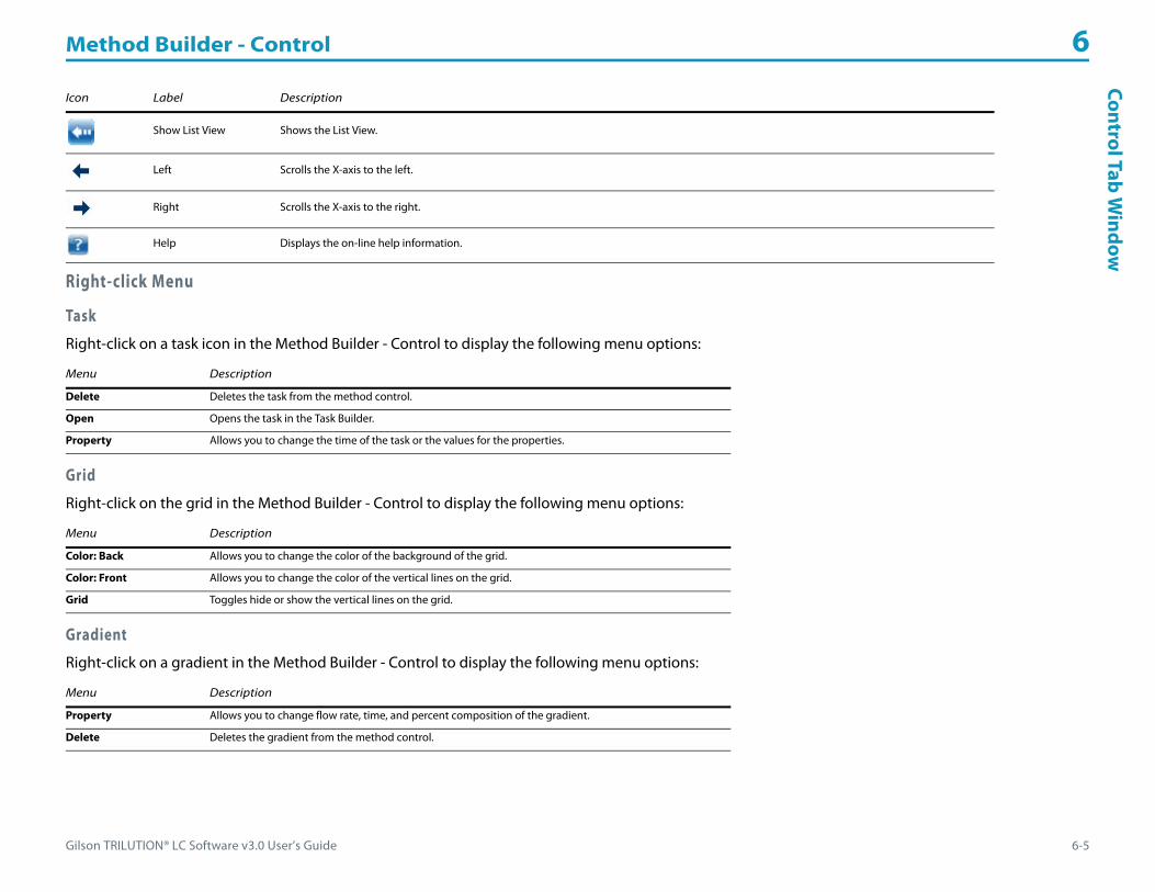
Gilson TRILUTION® LC Software v3.0 User’s Guide 6-5
Method Builder - Control 6Control Tab
Window
Right-click Menu
Task
Right-click on a task icon in the Method Builder - Control to display the following menu options:
Grid
Right-click on the grid in the Method Builder - Control to display the following menu options:
Gradient
Right-click on a gradient in the Method Builder - Control to display the following menu options:
Show List View Shows the List View.
Left Scrolls the X-axis to the left.
Right Scrolls the X-axis to the right.
Help Displays the on-line help information.
Menu Description
Delete Deletes the task from the method control.
Open Opens the task in the Task Builder.
Property Allows you to change the time of the task or the values for the properties.
Menu Description
Color: Back Allows you to change the color of the background of the grid.
Color: Front Allows you to change the color of the vertical lines on the grid.
Grid Toggles hide or show the vertical lines on the grid.
Menu Description
Property Allows you to change flow rate, time, and percent composition of the gradient.
Delete Deletes the gradient from the method control.
Icon Label Description
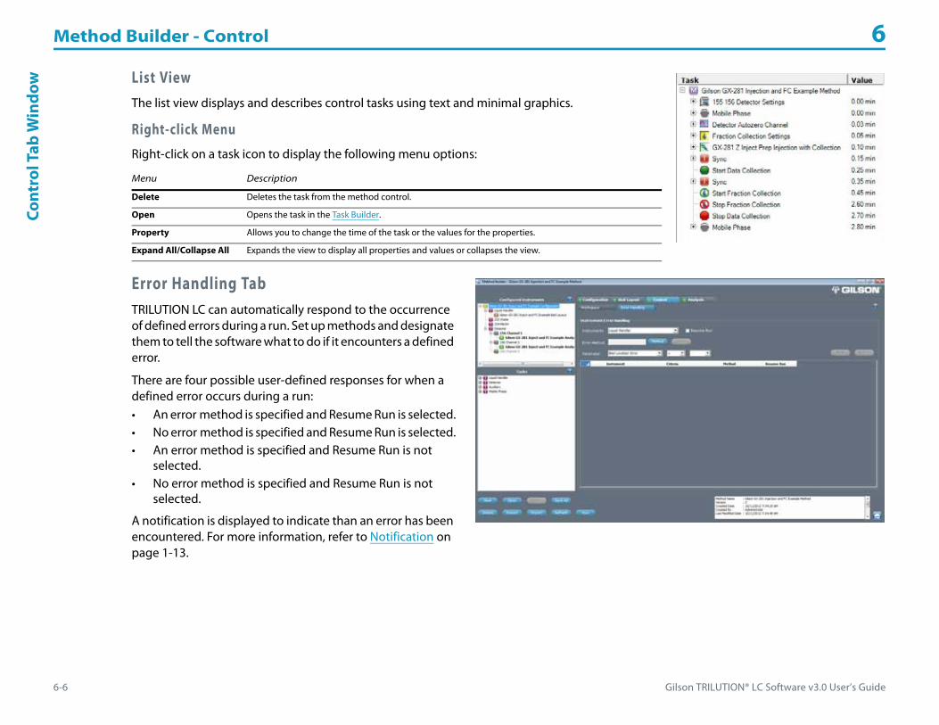
Method Builder - Control 6
6-6 Gilson TRILUTION® LC Software v3.0 User’s Guide
Cont
rol T
abW
indo
w List ViewThe list view displays and describes control tasks using text and minimal graphics.
Right-click Menu
Right-click on a task icon to display the following menu options:
Error Handling TabTRILUTION LC can automatically respond to the occurrence of defined errors during a run. Set up methods and designate them to tell the software what to do if it encounters a defined error.
There are four possible user-defined responses for when a defined error occurs during a run:• An error method is specified and Resume Run is selected.• No error method is specified and Resume Run is selected.• An error method is specified and Resume Run is not
selected.• No error method is specified and Resume Run is not
selected.
A notification is displayed to indicate than an error has been encountered. For more information, refer to Notification on page 1-13.
Menu Description
Delete Deletes the task from the method control.
Open Opens the task in the Task Builder.
Property Allows you to change the time of the task or the values for the properties.
Expand All/Collapse All Expands the view to display all properties and values or collapses the view.

Gilson TRILUTION® LC Software v3.0 User’s Guide 6-7
Method Builder - Control 6Control Tab
Window
How to Set Up Instrument Error Handling1 In the Method Builder, first create a configuration, bed layout, and control (refer to How to Create a Method on page 3-6), and then select
the Error Handling tab.2 Select the instrument to monitor from the drop-down list of instruments in the configuration.
3 Optionally, select an error method to run when this error is encountered. Only methods specified during the save as Use for Error Handling will be available.
4 Select the parameter from the drop-down list of possible parameters for the instrument selected.5 Select a valid mathematical operator (all are listed, but some would not make sense).6 Type the value to monitor in the field to the right of the mathematical operator.7 Optionally, select the Resume Run check box.8 Click New.9 Repeat all steps for additional instruments or set up additional parameters for the same instrument.
To monitor pressure when using a 331/332 or 333/334 Prep-Scale HPLC Pump combination, select only the 331 or 333.
Pressure for the 307 Make Up Pump should never exceed 1000 psi, which is the maximum pressure rating for the splitter. When using a 307 Make Up Pump, set up pressure error handling that will run an error method if the pressure is too high. The error method should include the Stop Make Up Pump task.
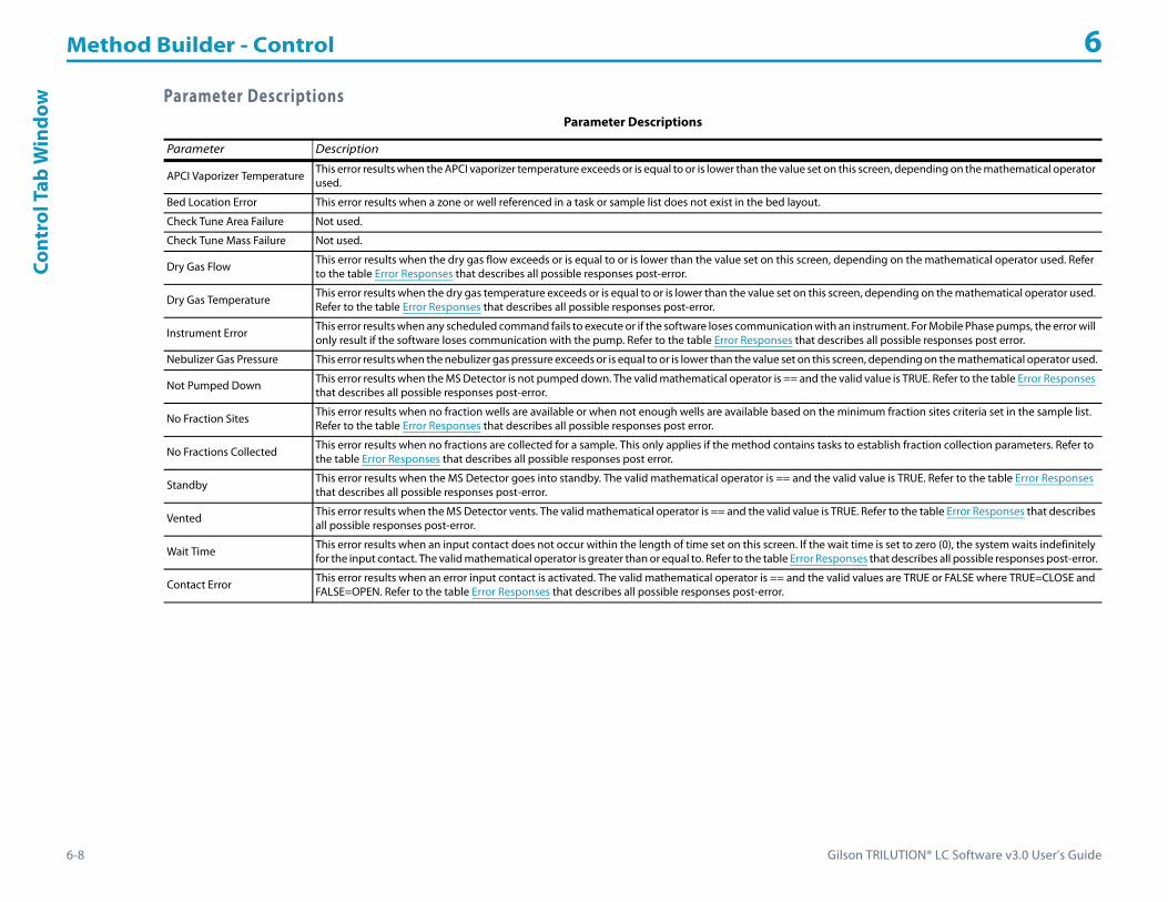
Method Builder - Control 6
6-8 Gilson TRILUTION® LC Software v3.0 User’s Guide
Cont
rol T
abW
indo
w Parameter DescriptionsParameter Descriptions
Parameter Description
APCI Vaporizer Temperature This error results when the APCI vaporizer temperature exceeds or is equal to or is lower than the value set on this screen, depending on the mathematical operator used.
Bed Location Error This error results when a zone or well referenced in a task or sample list does not exist in the bed layout.
Check Tune Area Failure Not used.
Check Tune Mass Failure Not used.
Dry Gas Flow This error results when the dry gas flow exceeds or is equal to or is lower than the value set on this screen, depending on the mathematical operator used. Refer to the table Error Responses that describes all possible responses post-error.
Dry Gas Temperature This error results when the dry gas temperature exceeds or is equal to or is lower than the value set on this screen, depending on the mathematical operator used. Refer to the table Error Responses that describes all possible responses post-error.
Instrument Error This error results when any scheduled command fails to execute or if the software loses communication with an instrument. For Mobile Phase pumps, the error will only result if the software loses communication with the pump. Refer to the table Error Responses that describes all possible responses post error.
Nebulizer Gas Pressure This error results when the nebulizer gas pressure exceeds or is equal to or is lower than the value set on this screen, depending on the mathematical operator used.
Not Pumped Down This error results when the MS Detector is not pumped down. The valid mathematical operator is == and the valid value is TRUE. Refer to the table Error Responses that describes all possible responses post-error.
No Fraction Sites This error results when no fraction wells are available or when not enough wells are available based on the minimum fraction sites criteria set in the sample list. Refer to the table Error Responses that describes all possible responses post error.
No Fractions Collected This error results when no fractions are collected for a sample. This only applies if the method contains tasks to establish fraction collection parameters. Refer to the table Error Responses that describes all possible responses post error.
Standby This error results when the MS Detector goes into standby. The valid mathematical operator is == and the valid value is TRUE. Refer to the table Error Responses that describes all possible responses post-error.
Vented This error results when the MS Detector vents. The valid mathematical operator is == and the valid value is TRUE. Refer to the table Error Responses that describes all possible responses post-error.
Wait Time This error results when an input contact does not occur within the length of time set on this screen. If the wait time is set to zero (0), the system waits indefinitely for the input contact. The valid mathematical operator is greater than or equal to. Refer to the table Error Responses that describes all possible responses post-error.
Contact Error This error results when an error input contact is activated. The valid mathematical operator is == and the valid values are TRUE or FALSE where TRUE=CLOSE and FALSE=OPEN. Refer to the table Error Responses that describes all possible responses post-error.

Gilson TRILUTION® LC Software v3.0 User’s Guide 6-9
Method Builder - Control 6Control Tab
Window
Error Responses
The following table describes all responses post error for all errors except Pressure. For Pressure error responses, refer to Pressure Error Responses (Mobile Phase Pumps)or Pressure Error Responses (307 Make Up Pump).
*Notification only appears if specified.
Error Responses
Error Method Specified? Resume Run? Response
Yes Yes • Error Method Execution notification appears*
• Control method terminates
• Error method executes
• Run resumes starting with the next step in the sample list
• Run Complete notification appears (with errors, refer to log for details)*
No Yes • Error Method Execution notification appears*
• Run resumes starting with the next step in the sample list
• Run Complete notification appears (with errors, refer to log for details)*
Yes No • Error Method Execution notification appears*
• Control method terminates
• Error method executes
• Application run terminates
• Run Complete notification appears (with errors, refer to log for details)*
No No • Error Method Execution notification appears*
• Application run terminates
• Run Complete notification appears (with errors, refer to log for details)*

Method Builder - Control 6
6-10 Gilson TRILUTION® LC Software v3.0 User’s Guide
Cont
rol T
abW
indo
w Pressure
This error results when the system pressure exceeds or is equal to or is lower than the value set on this screen. Refer to the table below that describes all possible responses post-error for mobile phase pumps.
*Notification only appears if specified.
Pressure Error Responses (Mobile Phase Pumps)
Error Method Specified? Resume Run? Response
Yes Yes • Pumps stop
• Control method terminates
• Error method executes
• Error Method Execution notification appears*
• Application run resumes starting with the next sample in the sample list
• Run Complete notification appears (with errors, refer to log for details)*
No Yes • Pumps stop
• Error Method Execution notification appears*
• Application run resumes starting with the next sample in the sample list
• Run Complete notification appears (with errors, refer to log for details)*
Yes No • Pumps stop
• Control method terminates
• Error method executes
• Error Method Execution notification appears*
• Run Complete notification appears (with errors, refer to log for details)*
No No • Pumps stop
• Error Method Execution notification appears*
• Run terminates
• Run Complete notification appears (with errors, refer to log for details)*

Gilson TRILUTION® LC Software v3.0 User’s Guide 6-11
Method Builder - Control 6Control Tab
Window
Refer to the table below that describes all possible responses post-error for the 307 Make Up Pump. Note that the pumps do not stop when a pressure error occurs. It is recommended to specify an error method that stops the pumps.
*Notification only appears if specified.
Modify Instrument Error HandlingModify instrument error handling by doing any of the following:• Setting up error handling for additional instruments in the configuration.• Setting up error handling with additional criteria for the same instrument.• Deleting instruments and/or parameters from the monitored list of criteria.
Right-click on a row in the table of monitored criteria and then select Delete to delete the criteria.• Modifying the instruments and/or parameters in the monitored list of criteria.
Select the row, make the desired changes, and then click Modify.
Delete Instrument Error Handling ConditionsTo delete error handling conditions set for an instrument:
1 Select the rows in the table.2 Right-click, and then select Delete.
Pressure Error Responses (307 Make Up Pump)
Error Handling Method Specified? Resume Run? Response
Yes Yes • Control method terminates
• Error method executes
• Error Method Execution notification appears*
• Application run resumes starting with the next sample in the sample list
• Run Complete notification appears (with errors, refer to log for details)*
No Yes • Error Method Execution notification appears*
• Application run resumes starting with the next sample in the sample list
• Run Complete notification appears (with errors, refer to log for details)*
Yes No • Control method terminates
• Error method executes
• Error Method Execution notification appears*
• Run Complete notification appears (with errors, refer to log for details)*
No No • Error Method Execution notification appears*
• Run terminates
• Run Complete notification appears (with errors, refer to log for details)*

Method Builder - Control 6
6-12 Gilson TRILUTION® LC Software v3.0 User’s Guide
Sche
dule
Tim
ed T
asks Schedule Timed Tasks
Each command issued in the method control is referred to as task. You can specify tasks that set the gradient profile, start or stop fraction collection, start or stop data collection, control the injector, or send or wait for a contact signal.
To add a task to the method, drag, and then drop the task into the workspace.
Within the properties box, there is a Time box for indicating the time point at which to start the task. This tells the software when to perform that function. To change the time or properties after it has been added to the workspace, double-click the task icon in the workspace.
When placing multiple tasks for one instrument, allow enough time for the instrument to perform one task before issuing another task. Separate the tasks by a minimum of 0.1 min.
For information about using variables for task properties, refer to Chapter 13, Working with Variables.
Modify Task Time and/or PropertiesTo change task time or properties, do either of the following:• Double-click the task icon.• Right-click the task icon and then select Property.
Modify TaskTo modify the Task:
1 Right-click the Task.2 Select Open. The Task will open in the Task Builder.
Delete Task from ControlTo remove a task from the control, select the task, and then do any of the following:• Right-click and then select Delete.• Press the DELETE key.• Drag the task to the trash bin.
Gilson-supplied tasks cannot be saved using the supplied name.

Gilson TRILUTION® LC Software v3.0 User’s Guide 6-13
Method Builder - Control 6H
ow to Create G
radient or Isocratic Conditions
How to Create Gradient or Isocratic ConditionsAn Isocratic and several linear gradient (Linear Gradient with Column Wash Out, Linear Gradient with No Column Wash Out, Multi Linear Gradient with Step and Column Wash Out, and Multi Linear Gradient with Column Wash Out) mobile phase templates are available as tasks in the Method Builder. Add a template to the method control and then, optionally, modify it by doing any of the following: Add a Point to the Mobile Phase Template, Modify Points on the Mobile Phase Template, or Delete Points on the Mobile Phase Template. Adding a different template to the method removes the existing template from the method. (Only one mobile phase template is allowed per method.) Templates default to 10 minutes.
Note: Unlike other tasks, gradient tasks cannot be opened in the Task Builder.
Add a Point to the Mobile Phase TemplateTo add a point to an existing template in the workspace:
1 Drag the Gradient task and then drop it in the workspace at the desired time and composition.2 Optionally, edit the properties by doing either of the following:
• Verify that the point is selected (green) and then drag the point to the desired composition and time, which is displayed above the workspace as the point is moved.
• Double-click the point, enter new values in the Gradient Properties dialog, and then click OK.
Or
1 Click to switch the Add Point toggle button from OFF ( ) to ON ( ).
2 Click anywhere in the workspace to add a point to the gradient at the desired composition and time. The Add Point toggle button switches back to OFF.
3 Optionally, edit the properties by doing either of the following:• Verify that the point is selected (green) and then drag the point to the desired time and composition, which is displayed above the
workspace as the point is moved.• Double-click the point, enter new values in the Gradient Properties dialog, and then click OK.

Method Builder - Control 6
6-14 Gilson TRILUTION® LC Software v3.0 User’s Guide
How
to C
reat
e G
radi
ent o
r Iso
crat
ic C
ondi
tion
s Modify Points on the Mobile Phase TemplateTo modify points, change the time, percent composition, or flow rate for the pumps.
Modify the Time
Single Point
To modify the time of a single point, do either of the following:• Click to select one point. (It changes to green.) Drag the point to the desired time. The
composition and time for the selected point being moved is displayed dynamically at the top left in the workspace.
• Double-click on a point, enter the time, and then click OK.
Gradient Group
To modify the time of a gradient group, click to select the first point and last point in the group (points and connecting lines change to green). Drag the group of points to the desired time. The composition and time for each selected point being moved is displayed dynamically at the top left in the workspace.
Modify the Percent Composition
Single Point
To modify the percent composition for a single point, do either of the following:• Click to select one point. (It changes to green.) Drag the point to the desired composition for the organic pump. The composition and time
for the selected point is displayed dynamically at the top left in the workspace.• Double-click on a point, enter the percent composition, and then click OK.
Gradient Group
To modify the percent composition for a gradient group, click to select the first point and last point in the group (points and connecting lines change to green). Drag the group of points to the desired composition for the organic pump. The composition and time for each selected point is displayed dynamically at the top left in the workspace.

Gilson TRILUTION® LC Software v3.0 User’s Guide 6-15
Method Builder - Control 6H
ow to Create G
radient or Isocratic Conditions
Modify the Flow Rate
Single Point
To modify the flow rate for a single point:
1 Double-click on a point.2 Enter the new flow rate or a variable.3 Click OK.
All Points
To modify the flow rate for all gradient points in the method:
1 Click the set flow rate button ( ).2 Enter the new flow rate.3 Click OK.

Method Builder - Control 6
6-16 Gilson TRILUTION® LC Software v3.0 User’s Guide
How
to C
reat
e G
radi
ent o
r Iso
crat
ic C
ondi
tion
s Delete Points on the Mobile Phase Template
Single PointTo delete a single point:
1 Click to select one point. (It changes to green.) 2 Do any of the following:
• Drag the point to the trash bin ( ) at the top of the window.• Right-click, and then select Delete.• Press the DELETE key.The software automatically connects remaining points.
Gradient GroupTo delete a gradient group:
1 Click to select the first point and last point in the group (points and connecting lines change to green). 2 Do either of the following:
• Drag the group of points to the trash bin ( ) at the top of the window. • Press the DELETE key.The software automatically connects remaining points.

Gilson TRILUTION® LC Software v3.0 User’s Guide 6-17
Method Builder - Control 6Fraction Collection Sim
ulation
Fraction Collection Simulation
How to Simulate Fraction Collection by Slope or LevelOptimize fraction collection settings using the fraction collection simulator:
1 Create a method that includes fraction collection by slope or level. For more information, refer to How to Create a Method on page 3-6.
2 Browse in a representative example chromatogram from a previous run’s results.
a) Click the Application Run Results tool ( ).b) From the drop-down menu, select the
application that was run to obtain the results that will be overlaid and the channel for which to overlay the results.
c) Double-click the Run Name/Method/Channel. The Select Iteration dialog appears.
d) On the Select Iteration dialog, do either of the following:• Double-click the iteration number.• Click to select the iteration number and then click OK.
The chromatogram overlays in the method control beginning at the Start Data Collection task. Optionally, modify the color or remove the chromatogram trace. For more information, refer to How to Modify the Appearance of Overlaid Results.
If using the Conditional Fraction Collection task with more than one data channel, complete steps a–d for each channel.
The fraction start and fraction end lines overlay the chromatogram showing the current fraction collection settings in effect.
If variables were used for any of the fraction collection parameters, modify the Default Value for the variable in the Variable Properties dialog. If the Value is not modified, 0 (the default Value) will be used in the simulation. For more information about creating variables, refer to Chapter 13, Working with Variables.
3 Optionally, modify the fraction collection parameters.
4 Click the Update Chromatogram tool ( ). The fraction start and fraction end lines update based on the modifications to the fraction
collection parameters.

Method Builder - Control 6
6-18 Gilson TRILUTION® LC Software v3.0 User’s Guide
Frac
tion
Col
lect
ion
Sim
ulat
ion How to Modify the Appearance of Overlaid Results
Click to open the Results List dialog.
The Results List dialog in the Method Builder provides previews of overlaid results for all channels and allows for changing the color of the data trace of each overlaid result or removing overlaid results.
To change the color of a trace, select the check box next to the preview of the trace, and then click Color. Select a color from the color palette.
To remove overlaid results, select the check box next to the preview of the trace, click Remove, and then click OK.

Gilson TRILUTION® LC Software v3.0 User’s Guide 7-1
Method Builder - Analysis 7
Using the options on the Analysis tab in the Method Builder, indicate how collected data are analyzed and reported. An analysis sets conditions for analyzing peaks in collected data. Creating an analysis includes setting peak parameters, naming peaks, and specifying parameters for generating reports.
To create an analysis, refer to How to Create an Analysis.

Method Builder - Analysis 7
7-2 Gilson TRILUTION® LC Software v3.0 User’s Guide
Ana
lysi
s Ta
bW
indo
w Analysis Tab WindowThe Analysis tab window in the Method Builder is a graphical interface used to organize the analysis tasks used in a method.
The Analysis tab window includes:• Peak Integration Tab• Report Tab• Error Handling Tab
Peak Integration TabThe Peak Integration tab in the Analysis window provides for setting analysis conditions and includes:• Integration Tasks• Peak Table• Background Removal• Void Volume Retention Time• Custom Calculation• Calibration• DAD Peak Purity• Spectral Library• Integration Tasks• List View
Integration TasksFor information about the integration tasks
( ), refer to Integration Tasks.

Gilson TRILUTION® LC Software v3.0 User’s Guide 7-3
Method Builder - Analysis 7A
nalysis TabW
indow
Peak TableThe peak table is where you tell the software about the peaks in data analyzed by the analysis. If you name peaks in the peak table, your reports refer directly to those peaks when reporting areas, heights, amounts, and so on.
The peak table has options for specifying:• Retention Time• Name• Reference Peak (Optional)• Group• IntStd (Internal Standard)• Color• Absolute Error and Relative Error
Right-click Options
Right-click on a row to display the following menu options:
Retention Time
Retention time is the retention time for the peak, defined by the APEX of the peak. The limit of resolution is hundredths of a minute (0.01 min).
Peak retention time is based on start of data collection indicated in the control executed at the same time as the analysis. If the beginning of data collection and injection are not synchronous, retention times reported deviate from actual retention times by their difference.
For more information, refer to How to Define Retention Time Windows.
Name
Name peaks and indicate their retention times in the peak table. Retention time information is obtained by injecting and acquiring traces for test samples.
Identify each peak for the component it represents.
Note: Reports are limited to displaying 20 characters for the peak name.
Menu Description
Add Inserts additional rows in the table for adding more peaks.
Delete Deletes the information for a peak by deleting the row in the table.
Group Creates peak groupings. For more information, refer to Group.

Method Builder - Analysis 7
7-4 Gilson TRILUTION® LC Software v3.0 User’s Guide
Ana
lysi
s Ta
bW
indo
w Reference Peak (Optional)
The software uses reference peaks to correct for retention time shifts that can occur during runs that analyze multiple samples. When the software notices a difference between the expected and actual retention time of a reference peak, it adjusts the retention times of the preceding non-reference peaks in its internal peak table.
You can designate an unlimited number of reference peaks in both calibration and unknown samples. An ideal reference peak is a large isolated peak with a consistent retention time. You can designate several reference peaks with retention times at the beginning, middle, and end of the run. If you designate just one reference peak, it should be a late-eluting peak.
Group
When you right-click on a row in the peak table and then select Group, options for grouping peaks appear in the Peak Group dialog. TRILUTION LC reports total area for all peaks selected in addition to the area of each individual peak.
Set Up Group Names
To indicate group names:
1 In the Peak Group dialog, type a name in the Group field.2 Click Insert. The group name is added to the list.3 Select the group name from the list.4 Click Group.
Group Peaks1 Select the row in the Peak Table.2 Right-click and then select Group.3 Select the group name from the list.4 Click Group.5 Repeat steps 1 through 4 to assign other peaks to groups.6 To remove a peak from a group, choose its name in the list and click Ungroup.
Delete Group Names
To delete group names:
1 Right-click the group name.2 Select Delete.

Gilson TRILUTION® LC Software v3.0 User’s Guide 7-5
Method Builder - Analysis 7A
nalysis TabW
indow
IntStd (Internal Standard)
When the IntStd check box is selected, it indicates that the peak is an internal standard. Enter the time frame during which to use the standard.
Start Time is the time at which to begin using the internal standard.
End Time is the time at which to stop using the internal standard. It must be later than the Start Time.
After typing the Start and End times, click Set to accept the values entered, click Clear to reset the values to 0 and clear the IntStd check box and close the dialog, or click Close to close the dialog without saving.
Color
Click to select from available color fills for the peak. The default is no fill.
Absolute Error and Relative Error
These are the retention time window parameters. To compensate for possible retention time drift, the software defines a window around the retention time for each peak. If a peak elutes at any time during that window, the software identifies it.
Absolute error is a constant amount of time on either side of a peak’s nominal retention time. The software automatically searches for eluted peaks at every named retention time plus or minus this amount of time.
Relative error is a percentage of peak retention time. Relative error, and, therefore, the width of retention time windows, increases with increasing retention time. Because late-eluting peaks are often broader than early peaks, the software uses this correction factor to improve the likelihood of locating late-eluting peaks.
The software uses the following formulas to calculate the beginning and end of any peak’s time window. Each peak’s time window appears in the graph pane.
Beginning: Ret. Time - [Abs. Error + (Ret. Time x Rel. Error)]
End: Ret. Time + (Abs. Error + Ret. Time x Rel. Error)
Background RemovalWhen you select the Background Removal check box and you set the Sample Type in the Sample List as BLANK, you indicate that its data will be subtracted from sample data.
Clearing the Background Removal check box indicates that you do not want the software to perform background subtraction.
For more information about sample types, refer to Sample Type on page 8-7.

Method Builder - Analysis 7
7-6 Gilson TRILUTION® LC Software v3.0 User’s Guide
Ana
lysi
s Ta
bW
indo
w Void Volume Retention TimeThis is the retention time of unretained effluent. This value is used to calculate Capacity (k').
Custom CalculationClick Custom Calculation on the Peak Integration tab to access the Custom Calculation Builder for creating a formula that the software will use to generate a value that can appear in a column in the table in the report. Specify a name for this expression and then optionally add it to the column contents for the report in any method. For more information, refer to Report Column Format - Report Type.
The Custom Calculation Builder lists quantities and mathematical operators that can be used in a formula. The following table provides a description of each calculable quantity.
Calculable Quantity Description
Amount Returns the peak amount
AMOUNT_% Returns the peak’s amount as a percentage of the total amount calculated for all named peaks in the sample
Area Returns the peak area
Area % Returns the peak’s area as a percentage of the total area of all integrated peaks in the sample
ASYMMETRY Returns the peak’s asymmetry, a value that identifies the shape of the peak, at 10% of peak height
BACK_RESOLUTION Returns the resolution of a peak in relation to the next peak
BACK_SLOPE Returns the slope at half height of the peak’s descending edge
CAPACITY Returns the capacity factor (k'), which measures the degree of retention
END_TIME Returns the time point, in seconds, at which integration stopped for the peak
END_VALUE Returns the returns the height at which integration stopped for the peak
FRONT_RESOLUTION Returns the resolution of the peak in relation to the previous peak
(Page 1 of 2)

Gilson TRILUTION® LC Software v3.0 User’s Guide 7-7
Method Builder - Analysis 7A
nalysis TabW
indow
CalibrationSelect the Calibration check box to tell the software that you will be running a calibration.
To tell the software how to construct the calibration curve and display the Calculation dialog, click Calibration.
When analyzing a sample, the software determines the peak area (or height) for each named component. For each peak, the software generates a calibration curve to determine the amount of that component in each unknown sample.
A component’s calibration curve plots the average peak area (or height) versus the amount injected.
For more information about calibrations, refer to Chapter 12, Calibrations.
FRONT_SLOPE Returns the slope at half height of the peak’s ascending edge
Height Returns the distance from the baseline to the maximum of the peak
HEIGHT_% Returns a peak’s height as a percentage of the total height of all integrated peaks in the sample
INJ_NUMBER Returns the number of the injection that corresponds to the peak
%_CONC Returns the peak’s percent concentration (as related to the total sample amount) of each reported peak
PLATE_NUMBER Returns the plate number, a value that indicates column efficiency
PURITY Returns the peak purity
RETENTION_TIME Returns the elapsed time, in seconds, between the point of injection and maximum of the peak
START_TIME Returns the time point, in seconds, at which integration began for the peak
START_VALUE Returns the height at which integration began for the peak
TAILING_FACTOR Returns the tailing factor at 5% of height.
WIDTH Returns the peak width, in seconds, at half height
Calculable Quantity Description
(Page 2 of 2)

Method Builder - Analysis 7
7-8 Gilson TRILUTION® LC Software v3.0 User’s Guide
Ana
lysi
s Ta
bW
indo
w Type
Area
Generates the curve based on the area of each standard peak.
Height
Generates the curve based on the height of each standard peak.
External Calibration
Generates the curve based on a previous calibration run. When this type is selected, the Browse External button becomes active to load an external calibration.
Internal Standard
Indicates that an internal standard will be used. Select whether to quantify the standard peaks by area or height when generating the curve.
Curve Fit
Cubic
The software generates a smooth curve that best represents the set of means. The curve may have two bends.
To determine the amount of that component in an unknown sample, the software determines where that component’s peak area intersects the calibration curve.
Linear
Using a best-fit method, the software constructs a line that best represents the set of means. This method minimizes the sum of the squares of the error distance between each mean and the line.
Linear through Zero
Using a best-fit method, the software constructs a line that best represents the set of means and includes the origin (0 area, 0 height) as a point.
Point to Point
The software connects the mean amount for each standard using a linear segment. For a single-standard calibration plot, the software generates a linear segment between the origin (0 area or 0 height, 0 amount) and mean peak area at the amount.
Quadratic
The software generates a smooth curve that best represents the set of means. The curve may have one bend.

Gilson TRILUTION® LC Software v3.0 User’s Guide 7-9
Method Builder - Analysis 7A
nalysis TabW
indow
DAD Peak PurityPeak Purity is a spectral comparison of the apex spectrum to spectra from across the peak. This comparison is used to check the purity of the peak. The spectra that are compared depend on the Number of Sampled Spectra selected.
To set peak purity options, click DAD Peak Purity.
Number of Sampled Spectra
Identifies the number of spectra to be evaluated and used in the peak purity algorithm for each integrated peak. Select 1, 3, 5, 7, 9, or All. TRILUTION LC selects spectra between the peak’s apex and peak height threshold. For more information, refer to the following diagrams:
Number of Sampled Spectra = 1
The apex spectrum is compared with the spectrum at the median.
Number of Sampled Spectra = 7
The apex spectrum is compared with equally spaced spectra between the median and the threshold intersections.
Number of Sampled Spectra = 3
The apex spectrum is compared with spectra at the median and the two peak threshold intersections.
Number of Sampled Spectra = 9
The apex spectrum is compared with equally spaced spectra between the median and the threshold intersections.
Number of Sampled Spectra = 5
The apex spectrum is compared with spectra at the median, the threshold intersections, and the mid-points between the median and threshold intersections.
Number of Sampled Spectra = All
The apex spectrum is compared with all spectra between the threshold intersections.

Method Builder - Analysis 7
7-10 Gilson TRILUTION® LC Software v3.0 User’s Guide
Ana
lysi
s Ta
bW
indo
w Wavelength Range: Minimum and Maximum (nm)
Identify the lowest and highest wavelength to use when calculating peak purity. You should limit the wavelength range to the area of absorption for your compounds of interest. TRILUTION LC’s peak purity algorithm may give misleadingly high results if wavelengths outside the UV/VIS absorption range for the compounds are included. The default range is 190–350 nm. The valid range is dependent on the detector.
Peak Height Threshold (%)
Specifies the percentage above the baseline at which spectra for the peak will be extracted. The selection of spectra is based on the peak height threshold and the number of sampled spectra.
Purity Threshold
If TRILUTION LC calculates a peak purity that is below this value, the peak is color filled red on the Peak Purity Display graph. If the calculated peak purity is above this value, the peak is color filled green on the Peak Purity Display graph. For more information about the Peak Purity Display graph, refer to Peak Purity Tab on page 11-22.
Spectral LibraryTRILUTION LC allows for assembling reference databases of spectral peaks of known compounds for searching and matching the databases’ contents to a chromatogram for an unknown sample and reporting the outcome.
To perform spectral matching on unknown peaks at run time automatically:
1 Click (DAD or Mass) Spectral Library. The Search (DAD or Mass) Spectral Library dialog appears.2 In the Search (DAD or Mass) Spectral Library dialog:
a) Select the check box next to the Library Name for each library to be searched.b) For each peak spectrum to match, do one of the following:
• Select the check box next to the Peak Name and under All Peaks to search all spectral library peaks.• Select the check box next to the Peak Name and under Time Period and then enter Start and End times to limit the search to
spectral library peaks whose retention times are within that time period.c) In the Match Threshold field, indicate the smallest match value to be reported. A match value of 1000 indicates a perfect match.
3 Click OK.

Gilson TRILUTION® LC Software v3.0 User’s Guide 7-11
Method Builder - Analysis 7A
nalysis TabW
indow
WorkspaceShows a graphic representation of timed tasks and peak retention time windows. Displays the analysis name.
Toolbar
Click an icon to perform the action described below:
Tool Label Description
Zoom In Makes the viewable time scale shorter.
Zoom Out Makes the viewable time scale longer.
Undo Reverses the last action when the last action was to add or delete a task or modify the task time graphically.
Redo Repeats the last action prior to an undo.
Trash Bin When an item in the workspace, is dragged to the trash bin, it is removed from the workspace.
Left arrow Scrolls the X-axis to the left.
Right arrow Scrolls the X-axis to the right.

Method Builder - Analysis 7
7-12 Gilson TRILUTION® LC Software v3.0 User’s Guide
Ana
lysi
s Ta
bW
indo
w
Right-click Menu
Task
Right-click on a task icon to display the following menu options:
Grid
Right-click on the grid to display the following menu options:
Update ChromatogramAfter making changes to the Peak Table, click the Update Chromatogram icon and the changes are reflected in the graph.
To remove the peak windows from the graph, right-click on the graph and then select Delete Peak Window.
Application Run Results To overlay results from a previous run, click the Application Run Results tool. This displays the Application Run Results dialog in which you can select the results from a previous run.
List View Print Prints the analysis tasks displayed in the list view.
Hide List View Hides the list view.
Show List View Shows the list view.
Help Displays the on-line help information.
Menu Description
Delete Deletes the task from the analysis.
Property Allows for changing the time of the task or the values for the properties.
Menu Description
Color: Back Allows for changing the color of the background of the grid.
Color: Front Allows for changing the color of the vertical lines on the grid.
Grid Toggles hide or show the vertical lines on the grid.
Tool Label Description
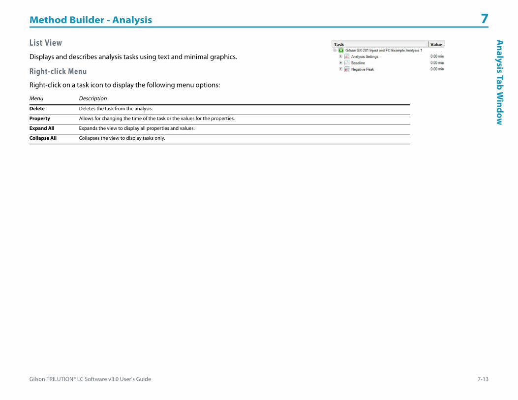
Gilson TRILUTION® LC Software v3.0 User’s Guide 7-13
Method Builder - Analysis 7A
nalysis TabW
indow
List ViewDisplays and describes analysis tasks using text and minimal graphics.
Right-click Menu
Right-click on a task icon to display the following menu options:
Menu Description
Delete Deletes the task from the analysis.
Property Allows for changing the time of the task or the values for the properties.
Expand All Expands the view to display all properties and values.
Collapse All Collapses the view to display tasks only.

Method Builder - Analysis 7
7-14 Gilson TRILUTION® LC Software v3.0 User’s Guide
Ana
lysi
s Ta
bW
indo
w Report TabThe report tab provides options for setting reporting conditions and report formats for the analysis report (refer to Analysis Report Elements), calibration report (refer to Calibration Report Elements), and summary reports.
The Report tab window includes:• Report Template• Report Column Format - Report Type• Report Column Format - Contents• Report Column Format - Custom Calculation• Auto Action• Data Channel Settings• Peak Inclusion/Exclusion Options• Company Logo & Address• Analysis Report Elements• Calibration Report Elements
Report TemplateSelect from two different templates:• Select Template 1 to display one chromatogram per page. • Select Template 2 to display more than one chromatogram per page. Neither fraction spectra nor
peak spectra will be displayed when the Template 2 option is selected.

Gilson TRILUTION® LC Software v3.0 User’s Guide 7-15
Method Builder - Analysis 7A
nalysis TabW
indow
Report Column Format - Report TypeTo view what is printed for each report, on the Method Builder - Analysis - Report tab, select the report type from the drop-down list.
Four report types can be modified:
Sample: This table is optionally included in the analysis report.
Sample Summary: This table is included in the unknown summary report.
Calibrator: This option is only available if the method has been specified as a calibration method. This table is optionally included in the calibration report.
Calibration Summary: This option is only available if the method has been specified as a calibration method. This table is included in the standard summary report.
Report Column Format - ContentsTo vary the format for reports, add or remove column contents.
To set report contents:
1 Select a Report Type from the drop-down list.2 Select the information type to be added to the report from the
Contents list.
3 Click the right arrow ( ) to add the information to Column Contents and to the report.
4 Click the up ( ) or down ( ) arrow to reorganize the columns. Columns listed up to down in the Column Contents will appear left to right in the report.
% Concentration
% Deviation
Only calculated for samples marked CONTROL.
((Nominal Amount – Unknown Amount)*100)/Nominal Amount

Method Builder - Analysis 7
7-16 Gilson TRILUTION® LC Software v3.0 User’s Guide
Ana
lysi
s Ta
bW
indo
w Amount
The actual amount entered in the sample list for a standard or the calculated amount for an unknown.
Amount %
The percentage of the peak in relation to the total amount of all named peaks.
Area
The area of the integrated peak.
Area %
Back Resolution
The resolution of a peak in relation to the next peak.
Back Slope
Back slope is the slope at half height of the descending edge of the peak.
Capacity (k')
Capacity is a measurement of the degree of retention.
Covariance

Gilson TRILUTION® LC Software v3.0 User’s Guide 7-17
Method Builder - Analysis 7A
nalysis TabW
indow
End Value
The end value is the signal at the end of the peak.
Fraction Area
The sum of the sub-fraction areas.
Fraction End Time
Elapsed time between the point of injection and the end of a fraction that occurs within 5 seconds of the end of the peak.
Fraction Ion(s)
The ions in each fraction of an integrated peak on the primary channel.
Fraction Site(s)
The location to which fractions for the peak are collected; reported as Zone, Well Number(s).
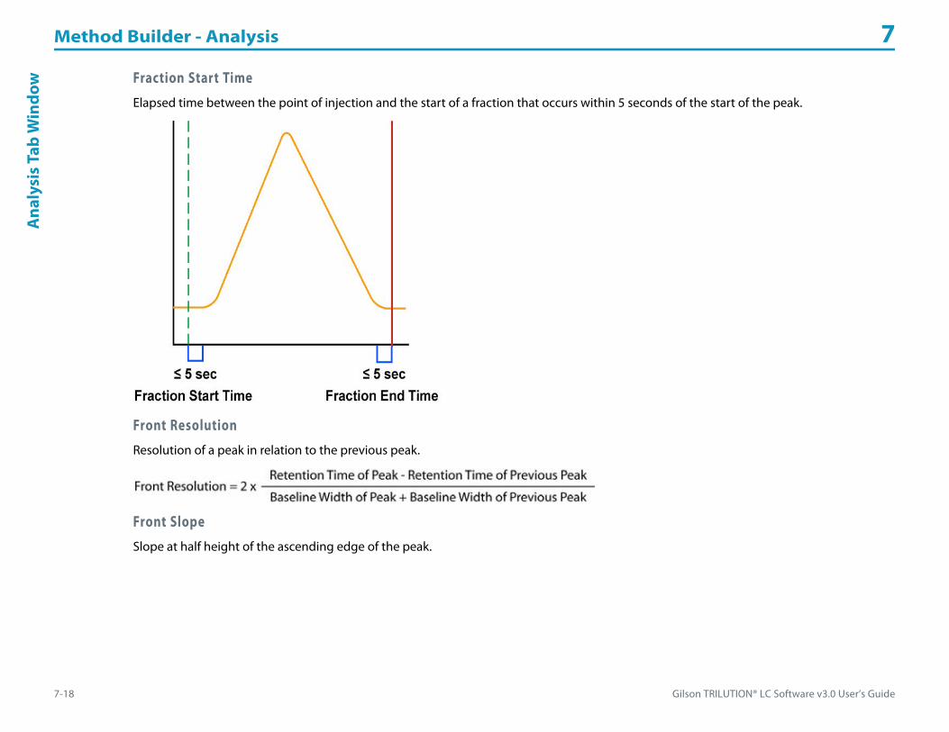
Method Builder - Analysis 7
7-18 Gilson TRILUTION® LC Software v3.0 User’s Guide
Ana
lysi
s Ta
bW
indo
w Fraction Start Time
Elapsed time between the point of injection and the start of a fraction that occurs within 5 seconds of the start of the peak.
Front Resolution
Resolution of a peak in relation to the previous peak.
Front Slope
Slope at half height of the ascending edge of the peak.

Gilson TRILUTION® LC Software v3.0 User’s Guide 7-19
Method Builder - Analysis 7A
nalysis TabW
indow
Height
Distance from the baseline to the maximum of the peak.
Height %
Injection Number
The number of the injection that corresponds to the peak.
Iteration Number
The number of the step in the sample list that corresponds to the peak.
Mean Area
where x is a measurement (area or height) and n is the number of measurements.
MS Spectral Match 1
The best mass spec spectral match according to spectral search criteria defined in the Method Builder - Analysis.
MS Spectral Match 2
The second best mass spec spectral match according to spectral search criteria defined in the Method Builder - Analysis.
MS Spectral Match 3
The third best mass spec spectral match according to spectral search criteria defined in the Method Builder - Analysis.

Method Builder - Analysis 7
7-20 Gilson TRILUTION® LC Software v3.0 User’s Guide
Ana
lysi
s Ta
bW
indo
w Nominal Amount
The nominal amount entered in the sample list.
Notes
The Notes entered in the sample list.
Number Average
The total number of injections.
Peak Asymmetry
Factor that identifies the shape of the peak. If this value is 1, the peak is symmetric. If the peak is skewed to the right (tailing peak), this value is greater than 1. If the peak is skewed to the left (fronting peak), this value is less than 1.
Peak End Time
Elapsed time between the point of injection and the end of the peak.
Peak Name
Name assigned to the peak in the peak table.
Peak Start Time
Elapsed time between the point of injection and the start of the peak.

Gilson TRILUTION® LC Software v3.0 User’s Guide 7-21
Method Builder - Analysis 7A
nalysis TabW
indow
Peak Purity
The calculated peak purity value.
Peak Width 1/2 HT
Peak Width at Half Height = Time at Half Height of Descending Edge - Time at Half Height of Ascending Edge
Peak Width 10%
Peak Width at 10% = Time at 10% Height of Descending Edge - Time at 10% Height of Ascending Edge
Plate Number
This value can be used to determine column efficiency.
Retention Time
Elapsed time between the point of injection and the maximum of the peak.
Sample Description
The sample description assigned in the sample list.

Method Builder - Analysis 7
7-22 Gilson TRILUTION® LC Software v3.0 User’s Guide
Ana
lysi
s Ta
bW
indo
w Sample Location
The location of the original sample; reported as Zone, Well Number.
Sample Name
The sample name assigned in the sample list.
Spectral Match 1The best spectral match according to spectral search criteria defined in the Method Builder - Analysis.
Spectral Match 2
The second best spectral match according to spectral search criteria defined in the Method Builder - Analysis.
Spectral Match 3
The third best spectral match according to spectral search criteria defined in the Method Builder - Analysis.
Standard Deviation
Square Root (Number of Observation * Summation(square(value)) – Square(Summation(value)) / (Number of Observations * (Number of Observations – 1)))
Start Value
The signal at the start of the peak.
Sub Fraction Area
The area of each sub fraction of a peak. When added together, the sum is the fraction area.
Tailing Factor
Total Fraction Ion(s)
All unique ions in fractions of an integrated peak on the primary channel.

Gilson TRILUTION® LC Software v3.0 User’s Guide 7-23
Method Builder - Analysis 7A
nalysis TabW
indow
Report Column Format - Custom CalculationOptionally, create a custom calculation. (For more information, refer to Custom Calculation.) After creating custom calculation(s), optionally, use this button to add it to the column contents for the report in any method.
Auto Action
Auto Print
Select this check box to print an analysis report automatically after each sample completes. If a method uses multiple data channels with multiple analyses, Auto Print is only available for the Default Analysis for each data channel.
Auto Export
Select this check box to export an analysis report automatically at the end of the run. The software names the exported file automatically. The file is named RUN NAME_METHOD NAME(INJECTION NUMBERS)DATA CHANNEL NAME_ANALYSIS NAME. The file type (and therefore file extension) is dependent on the Format specified.
Use of the auto export feature on any channel is NOT recommended when using a Flexar SQ 300 MS Detector.
Format
Select a format from the drop-down list for the auto-exported file.

Method Builder - Analysis 7
7-24 Gilson TRILUTION® LC Software v3.0 User’s Guide
Ana
lysi
s Ta
bW
indo
w Data Channel SettingsIn the Data Channel Settings dialog, you indicate how the lines for the data channels are displayed on the chromatogram plot during the run, in the results, and in reports.
To specify data channel parameters:
1 On the Analysis Report tab, click Data Channel Settings.2 Review the information in the areas of the dialog box and modify the information, if necessary.
% Offset
Use this parameter to move any additional channel’s line away from the horizontal axis (and from other channel lines) on chromatogram plot. Express the offset as a percent of 100.
Show All Channels
This parameter, which is selected by default, specifies whether all channels or just one channel will be displayed on the chromatogram plot. Display differs depending on the area of the software: Application Run, Results, or Reports.
Application Run
Lines for all channels being used will be displayed during the application run.
Results and Reports
Select this check box to display a line for each channel being used that has an associated analysis.
Clear the check box to display the line for the selected channel only.
Thickness
Identifies the width of the line in pixels.
Color
Identifies the color of the line in the application run, results, and reports.
Pre-defined (not user-defined) colors will be used if data channels share an analysis.
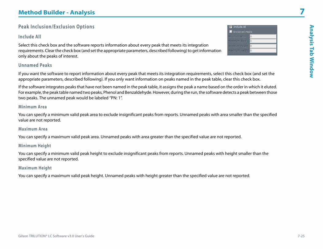
Gilson TRILUTION® LC Software v3.0 User’s Guide 7-25
Method Builder - Analysis 7A
nalysis TabW
indow
Peak Inclusion/Exclusion Options
Include All
Select this check box and the software reports information about every peak that meets its integration requirements. Clear the check box (and set the appropriate parameters, described following) to get information only about the peaks of interest.
Unnamed Peaks
If you want the software to report information about every peak that meets its integration requirements, select this check box (and set the appropriate parameters, described following). If you only want information on peaks named in the peak table, clear this check box.
If the software integrates peaks that have not been named in the peak table, it assigns the peak a name based on the order in which it eluted. For example, the peak table named two peaks, Phenol and Benzaldehyde. However, during the run, the software detects a peak between those two peaks. The unnamed peak would be labeled “PN: 1”.
Minimum Area
You can specify a minimum valid peak area to exclude insignificant peaks from reports. Unnamed peaks with area smaller than the specified value are not reported.
Maximum Area
You can specify a maximum valid peak area. Unnamed peaks with area greater than the specified value are not reported.
Minimum Height
You can specify a minimum valid peak height to exclude insignificant peaks from reports. Unnamed peaks with height smaller than the specified value are not reported.
Maximum Height
You can specify a maximum valid peak height. Unnamed peaks with height greater than the specified value are not reported.
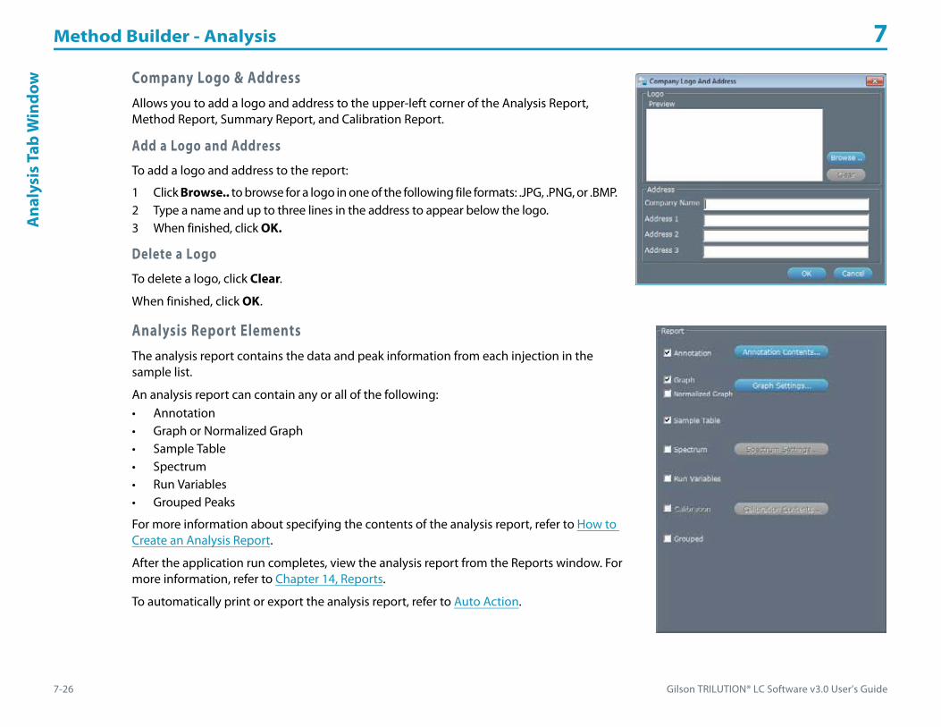
Method Builder - Analysis 7
7-26 Gilson TRILUTION® LC Software v3.0 User’s Guide
Ana
lysi
s Ta
bW
indo
w Company Logo & AddressAllows you to add a logo and address to the upper-left corner of the Analysis Report, Method Report, Summary Report, and Calibration Report.
Add a Logo and Address
To add a logo and address to the report:
1 Click Browse.. to browse for a logo in one of the following file formats: .JPG, .PNG, or .BMP.2 Type a name and up to three lines in the address to appear below the logo.3 When finished, click OK.
Delete a Logo
To delete a logo, click Clear.
When finished, click OK.
Analysis Report ElementsThe analysis report contains the data and peak information from each injection in the sample list.
An analysis report can contain any or all of the following:• Annotation• Graph or Normalized Graph• Sample Table• Spectrum• Run Variables• Grouped Peaks
For more information about specifying the contents of the analysis report, refer to How to Create an Analysis Report.
After the application run completes, view the analysis report from the Reports window. For more information, refer to Chapter 14, Reports.
To automatically print or export the analysis report, refer to Auto Action.

Gilson TRILUTION® LC Software v3.0 User’s Guide 7-27
Method Builder - Analysis 7A
nalysis TabW
indow
Calibration Report Elements A Calibration Report can contain any or all of the following:• Annotation• Graph or Normalized Graph• Sample Table• Run Variables• Plot• Plot Table
Select the check box for each element to include. The check boxes for the Plot and Plot Table are found in the Calibration Contents dialog.
Annotation
Choose which parts of the Calibration Report’s annotation will be viewed and printed.
1 On the Method Builder Analysis Report tab, click Annotation Contents....2 When the Annotation Contents dialog appears, use the check boxes to turn off or on parts of
the annotation.
Graph or Normalized Graph
Choose whether to display a graph, a normalized graph, or both and how peaks are labeled in the report’s graphs and the run results.
1 On the Method Builder Analysis Report tab, click Graph Settings... .2 When the Peak Information and Graph Settings dialog appears, use the check boxes to turn off or on labels on the chromatograms.3 Specify the size of the chromatogram (Graph Size) as a percentage of the page.4 Optionally, add the grid line to the chromatograms (select the check box) and change the grid color.5 Optionally, set custom axis settings (not applicable for normalized graphs). If setting a custom setting for one axis, the other axis is scaled
automatically.
Sample Table
The columns in the table are chosen in the Report Column Format when Calibrator is chosen as the Report Type. The default columns are Peak Name, Mean Area, Amount, Standard Deviation, Covariance, and Number Average. For more information, refer to Report Column Format - Contents.
Run Variables
If this check box is selected, variables shown in the sample list will be reported with the values used to satisfy those variables.

Method Builder - Analysis 7
7-28 Gilson TRILUTION® LC Software v3.0 User’s Guide
Ana
lysi
s Ta
bW
indo
w Calibration
Choose whether to include the calibration plot and/or plot table.
1 On the Method Builder Analysis Report tab, click Calibration Contents....2 When the Calibration Contents dialog appears, use the check boxes to turn off or on the plot and the plot
table.

Gilson TRILUTION® LC Software v3.0 User’s Guide 7-29
Method Builder - Analysis 7A
nalysis TabW
indow
Error Handling TabError Handling tells the software what types of checks to do on the calculated peak amounts and how the software responds if it detects an error.
The software can perform validation and system performance checks on peaks in samples.
The Error Handling tab lists the error conditions that the software should be aware of when analyzing data using the method.
For information about control error handling, refer to Error Handling Tab on page 6-6.
How to Set Up Analysis Error HandlingSelecting a peak name and indicating error conditions for it activates error handling. What happens during a run then depends on whether an error method is chosen and whether the Resume Run check box is selected.• If neither a method nor the Resume Run check box is selected, the run is stopped when the error condition is met.• If both a method and the Resume Run check box are selected, the software executes the error method and then proceeds to the next step
in the sample list.• If a method is indicated but the Resume Run check box is not selected, it executes the error method and then stops the run.• If a method is not indicated, but the Resume Run check box is selected, the software finishes the current step and proceeds to the next step
in the sample list.

Method Builder - Analysis 7
7-30 Gilson TRILUTION® LC Software v3.0 User’s Guide
Ana
lysi
s Ta
bW
indo
w Indicate Analysis Error Conditions
To specify error conditions:
1 Peak Name. Choose the name of the peak to monitor. The list box shows the peaks set in the peak table.2 Error Method. Choose the method to execute when the selected error condition is met. Only methods specified during the save to use for
error handling will be available.3 Resume Run. Select this check box if the run should continue even if an error has been encountered. Refer to How to Set Up Analysis
Error Handling to see how this check box affects what happens during the run or re-analysis.4 Parameter. In the list box, choose the peak calculation or value to monitor. Then, from the drop-down list, choose one of the mathematical
operators: greater than, less than, outside range, less than or equal to, equal to or greater than, or equal to. In the text box, type the monitor value.For example, select the parameter INJECTIONS W/O PEAK to activate error handling if a peak is not detected in an injection.Note: When monitoring % CONCENTRATION, the software only monitors sample type STANDARD.
5 Click New.6 Repeat for the next peak or parameter.
Modify Analysis Error ConditionsTo modify an error condition set for a peak:
1 Select the row with the peak name in the table.2 Make desired changes.3 Click Modify.
Delete Analysis Error ConditionsTo delete error conditions set for a peak:
1 Select the rows in the table.2 Right-click and then select Delete.

Gilson TRILUTION® LC Software v3.0 User’s Guide 7-31
Method Builder - Analysis 7H
ow to Create an A
nalysis
How to Create an Analysis1 Right-click on a data channel in the Configured Instruments panel and then do one of the following:
• Select New Analysis. Set the peak integration (refer to Peak Integration Tab), report (refer to Report Tab), and error handling options (refer to Error Handling Tab) for the analysis.
• Select Browse Analysis and then Saved Analysis to associate an existing analysis from any method to the data channel. Any changes to the analysis will be reflected in all copies of the analysis with the same name in any method.
• Select Browse Analysis to associate an existing analysis from the current method to the data channel. Any changes to the analysis will be reflected in all copies of the analysis with the same name.
2 Optionally, select Rename Channel to rename the data channel.3 Right-click on an analysis and then select Default Analysis to specify which analysis TRILUTION LC will use during the run for the associated
data channel. 4 Optionally, right-click on an analysis and then select Rename Analysis to rename the analysis.
Remove an AnalysisOn the Configured Instruments panel, select an analysis, and then right-click to view the submenu. From the submenu, select Remove Analysis.

Method Builder - Analysis 7
7-32 Gilson TRILUTION® LC Software v3.0 User’s Guide
Inte
grat
ion
Task
s Integration TasksWhen you first open an Analysis window (Peak Integration tab), the following integration events are set at 0.00 minutes:• Default Baseline• Inhibit Negative Peak Integration• Analysis Settings
For most separations, these are the only events to set; however, you can delete or modify these events, if necessary.
Note: Integration always begins at analysis time 0. Analysis time 0 begins at the start of data collection in the control. If integration tasks are deleted or moved away from time 0, the default parameters for the integration tasks will be used at time 0 until the first integration task. The default baseline is Default Baseline. Negative Peak integration is inhibited. The default Front and Back Slopes are 25, the default Peak Width is 0.20 min, and the default Peak Filter is 0.00 min.
Note: Removing the Inhibit Negative Peak Integration event does not turn on negative peak integration. Insert an Enable Negative Peak Integration event at the time point at which to start negative peak integration.
To be integrated, a peak must elute during data collection. Furthermore, every contour rising from and falling to the baseline must meet the peak detection criteria. 600 peaks per run can be integrated.
The software’s ability to integrate peaks depends on the Analysis Settings. These settings give information to the software about the size and shape of your peaks and the noise level riding the baseline. However, if one or more peaks of interest are not integrated, modify some or all of these parameters before subsequent runs or re-analysis processing.

Gilson TRILUTION® LC Software v3.0 User’s Guide 7-33
Method Builder - Analysis 7Integration Tasks
The following table shows the icons representing integration events.
Tool Icon Description
Baseline Default BaselineDefault Baseline
Baseline Horizontal BaselineHorizontal Baseline
Baseline All Valleys BaselineAll Valleys
Baseline Tangent Skim BaselineTangent Skim
Baseline Next Valley BaselineNext Valley
Integration Inhibit Integration Enable IntegrationInhibit/Enable Integration
Negative Peak Inhibit Negative Peak Integration Enable Negative Peak IntegrationNegative Peak
Analysis Settings Analysis SettingsAnalysis Settings
Fraction Collection Start Integration by Fraction Collection Stop Integration by Fraction CollectionStart/Stop Integration by Fraction Collection

Method Builder - Analysis 7
7-34 Gilson TRILUTION® LC Software v3.0 User’s Guide
Inte
grat
ion
Task
s Analysis SettingsConsider the angle of the peak’s ascending and descending edge when setting the values for Front Slope and Back Slope. The default value for front and back slopes is 25. If the peak has significant tailing, the Back Slope value should be increased to reduce the amount of the tail that is integrated or decreased to increase the amount of the tail that is integrated. Smaller Front Slope values will integrate smaller, sharper peaks. To reduce the number of small peaks integrated, increase the Front Slope value.
The Peak Width setting is the size of the data window that is used to calculate whether the slope condition has been met. The default is 0.20 min. If the trace has a lot of noise, set a higher value to reduce the number of smaller peaks that are integrated or set a lower value to increase the number of smaller peaks that are integrated.
By default co-eluted peaks are not integrated. To integrate co-eluted peaks, select the Co-eluted Peaks check box.
Peak Filter is defaulted to 0 min, indicating that Peak Filter will not be used when determining integration. A peak will not be integrated if the peak width at half height is less than or equal to the Peak Filter setting.
BaselineTRILUTION LC provides several baseline options. If you change the baseline selection, the software uses the first affected peak to determine when to use the new selection. The first affected peak is the peak whose end follows the scheduled time. Therefore, when applying an alternate baseline selection within a series of peaks, enter a time that coincides with the peak retention time. Change baselines sparingly and carefully so that data are analyzed in a meaningful way.
Accurate peak integration depends on the shape of the baseline, which in turn depends on the peak shape and on the resolution from neighboring peaks.
Changes to the baseline remain in effect until the next Baseline task is scheduled.
For examples of the effect of baseline selection on merged or resolved peaks, refer to Effect of Baseline Selection in Appendix C, Peak Integration.
A description of each baseline option follows. The default is Default Baseline.

Gilson TRILUTION® LC Software v3.0 User’s Guide 7-35
Method Builder - Analysis 7Integration Tasks
Default BaselineBaselines are drawn from the start and end of each peak. If the software encounters merged peaks (no baseline resolution between peaks), Default Baseline draws a straight line from the start of the first merged peak to the end of the last merged peak, and drops perpendicular lines from the valley of each merged peak to the new baseline. The start and end point of each peak may be shifted to prevent the baseline from crossing the chromatogram trace.
Horizontal BaselineDraws a forced horizontal baseline. The first peak after the horizontal baseline task determines the baseline level. If the trace drops below the current horizontal baseline, a new horizontal baseline is drawn. Perpendiculars are drawn from each peak start and each peak end to the baseline. The baseline level remains the same until a peak (peak start or peak end) falls below the horizontal baseline or a new horizontal baseline task is scheduled.
Horizontal Baseline Task at Time 0 Horizontal Baseline Tasks at Times 0 and 0.2 min

Method Builder - Analysis 7
7-36 Gilson TRILUTION® LC Software v3.0 User’s Guide
Inte
grat
ion
Task
s All ValleysThe All Valleys option forces the start and end point to the valley of the chromatogram trace. The start and end point of each peak may be shifted to prevent the baseline from crossing the chromatogram trace.
Tangent SkimBaselines are drawn from the start and end of each peak. If the software encounters merged peaks (no baseline resolution between peaks), Tangent Skim moves the integration endpoint of the first merged peak to the end of all the merged peaks, and then draws a line tangent to all of the remaining peaks within the start and new end of first merged peak. The start and end point of each peak may be shifted to prevent the baseline from crossing the chromatogram trace.
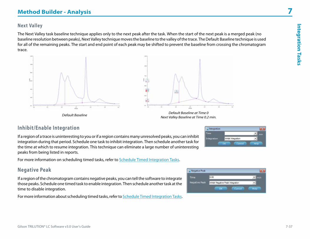
Gilson TRILUTION® LC Software v3.0 User’s Guide 7-37
Method Builder - Analysis 7Integration Tasks
Next ValleyThe Next Valley task baseline technique applies only to the next peak after the task. When the start of the next peak is a merged peak (no baseline resolution between peaks), Next Valley technique moves the baseline to the valley of the trace. The Default Baseline technique is used for all of the remaining peaks. The start and end point of each peak may be shifted to prevent the baseline from crossing the chromatogram trace.
Inhibit/Enable IntegrationIf a region of a trace is uninteresting to you or if a region contains many unresolved peaks, you can inhibit integration during that period. Schedule one task to inhibit integration. Then schedule another task for the time at which to resume integration. This technique can eliminate a large number of uninteresting peaks from being listed in reports.
For more information on scheduling timed tasks, refer to Schedule Timed Integration Tasks.
Negative PeakIf a region of the chromatogram contains negative peaks, you can tell the software to integrate those peaks. Schedule one timed task to enable integration. Then schedule another task at the time to disable integration.
For more information about scheduling timed tasks, refer to Schedule Timed Integration Tasks.
Default BaselineDefault Baseline at Time 0
Next Valley Baseline at Time 0.2 min.

Method Builder - Analysis 7
7-38 Gilson TRILUTION® LC Software v3.0 User’s Guide
Inte
grat
ion
Task
s Start/Stop Integration by Fraction CollectionUses slope, specified in the Analysis Settings integration task, to determine the integration baseline and uses the fraction collection start and stop lines for the start and end of the baseline. The fraction collection start (solid green vertical line) and end (dashed red vertical line) must occur within the peak analysis start (arrow up) and peak analysis end (arrow down) for the peak to be integrated using integration by fraction collection. The following diagrams show how the integration of a peak differs when integrating by fraction collection. For this example, the analysis start and end are outside the fraction collection window.
Diagram 1: Fraction Collection by Level - Integration by Analysis Settings
Diagram 1a: Fraction Collection by Level - Integration by Analysis Settings
Diagram 1b: Fraction Collection by Level - Integration by Fraction Collection

Gilson TRILUTION® LC Software v3.0 User’s Guide 7-39
Method Builder - Analysis 7H
ow to D
efine Retention Time
Window
s
How to Define Retention Time WindowsReference and non-reference peaks in unknown samples are located by matching actual retention times to retention times listed in the analysis peak table. To compensate for possible retention time drift, the software defines a time window around each expected peak. It finds an expected peak if that peak lies within the retention time window.
You can modify the Absolute Error and/or Relative Error parameters to control the width of retention time windows.
Absolute error is a constant amount of time flanking a peak’s nominal retention time. The software automatically searches for eluted peaks at every named retention time plus or minus this amount of time.
Relative error is a percentage of peak retention time. Relative error and, therefore, the width of retention time windows, increases with increasing retention time. Because late-eluting peaks are often broader than early peaks, the software adds this correction factor to improve the likelihood of locating late-eluting peaks.
You can calculate the beginning and end of any peak’s time window using the following formulas:
Beginning: Ret. Time - [Abs. Error - (Ret. Time x Rel. Error)]
End: Ret. Time + (Abs. Error + Ret. Time x Rel. Error)
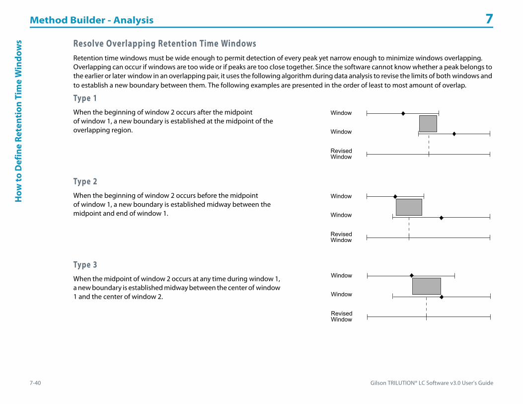
Method Builder - Analysis 7
7-40 Gilson TRILUTION® LC Software v3.0 User’s Guide
How
to D
efin
e Re
tent
ion
Tim
eW
indo
ws Resolve Overlapping Retention Time Windows
Retention time windows must be wide enough to permit detection of every peak yet narrow enough to minimize windows overlapping. Overlapping can occur if windows are too wide or if peaks are too close together. Since the software cannot know whether a peak belongs to the earlier or later window in an overlapping pair, it uses the following algorithm during data analysis to revise the limits of both windows and to establish a new boundary between them. The following examples are presented in the order of least to most amount of overlap.
Type 1When the beginning of window 2 occurs after the midpoint of window 1, a new boundary is established at the midpoint of the overlapping region.
Type 2When the beginning of window 2 occurs before the midpoint of window 1, a new boundary is established midway between the midpoint and end of window 1.
Type 3When the midpoint of window 2 occurs at any time during window 1, a new boundary is established midway between the center of window 1 and the center of window 2.

Gilson TRILUTION® LC Software v3.0 User’s Guide 7-41
Method Builder - Analysis 7H
ow to U
se the Peak Table During D
ata Analysis
How to Use the Peak Table During Data AnalysisWhen the software begins to analyze data collected during a run, it looks for the reference peaks and non-reference peaks that you identified in the peak table. It knows where to look because you set the peak retention times and retention time window parameters.
After finding the peaks, the software checks the retention times of those peaks and updates its peak table so it knows when to expect those peaks in the next sample.
Reasons for Missing PeaksThe software might fail to identify reference or non-reference peaks if:• the peak slope, peak width, and peak filter were incompatible with chromatogram peaks• the wrong sample was injected• changing chromatographic conditions (flow rate, mobile phase composition, pressure, temperature) or leaks in the system resulted in
inconsistent retention times• an insufficient number or a poor choice of reference peaks were named • the absolute error and/or relative error need to be adjusted
Locate Reference PeaksWhen you create a peak table, you can specify retention times for one or more reference peaks. The software looks for peaks named in the peak table whose actual retention times fall within the reference peaks’ time windows.
Use reference peaks cautiously. An ideal reference peak is a large, well-separated, isolated peak with a consistent retention time.
If, during data analysis, it finds a peak in a retention time window, it presumes it found the desired reference peak. As the software identifies reference peaks, it constructs an internal graph of actual retention times versus expected retention times.
If two or more peaks fall within the same reference peak time window, it chooses the largest one as the reference peak. If two peaks in a window are equally tall, the earliest peak is chosen as the reference peak.

Method Builder - Analysis 7
7-42 Gilson TRILUTION® LC Software v3.0 User’s Guide
How
to U
se th
e Pe
ak T
able
Dur
ing
Dat
a A
naly
sis Locate Non-Reference Peaks
Using the internal graph, described previously, the software updates the expected retention times (and retention time windows) for all non-reference peaks named in the Peak Table. It then looks for non-reference peaks named on the peak table whose actual retention times fall within a corrected retention time window.
If the software finds such a peak, it presumes it is the desired non-reference peak. If two or more non-reference peaks fall within the same window, it chooses the earliest peak whose retention time is closest to the window’s center.
Update Peak Retention TimesOver the course of multi-sample runs, retention times could drift so much that peaks would elute outside their original time windows. To ensure that the software always knows the most likely retention time of each named peak, the software continuously updates the retention time windows of reference and non-reference peaks on its internal peak table.
In the first sample, the software expects that named peaks have the retention time specified in the peak table. In each subsequent sample, it adjusts the expected retention time according to information it gathers during the run.
The new midpoint of each peak’s retention time window is calculated as a weighted sum of each peak’s previously determined window midpoint (75%) plus its retention time in the current sample (25%). A weighted sum is necessary to minimize the influence of a single bad sample in a multi-sample run.
For example, after several samples, the midpoint of a peak’s retention time window is at 3 minutes. In the next sample, that peak’s retention time was 3.2 minutes. On the software’s peak table, the midpoint of the retention time window is adjusted to 3.05 minutes.
(3 minutes x 0.75) + (3.2 minutes x 0.25) = 3.05 minutes
This updating only occurs if all reference peaks are found in the current sample. If all reference peaks are found, the retention time window of each reference and non-reference peak found during that sample is updated as described previously.

Gilson TRILUTION® LC Software v3.0 User’s Guide 7-43
Method Builder - Analysis 7H
ow to Create an A
nalysis Report
How to Create an Analysis ReportThe analysis report contains the data and peak information from each injection in the sample list.
An analysis report can contain any or all of the following:• Annotation• Graph or Normalized Graph• Sample Table• Spectrum• Run Variables• Grouped Peaks
Specify contents of the analysis report on the Method Builder - Analysis - Report tab by selecting the check box under Analysis Report Elements for each element to include.
After the application run completes, view the analysis report from the Reports window. For more information, refer to Chapter 14, Reports.
Annotation ContentsChoose which parts of the report’s annotation will be viewed and printed.
1 On the Method Builder - Analysis - Report tab, click Annotation Contents... .2 When the Annotation Contents dialog appears, use the check boxes to turn off or on parts of
the annotation.

Method Builder - Analysis 7
7-44 Gilson TRILUTION® LC Software v3.0 User’s Guide
How
to C
reat
e an
Ana
lysi
s Re
port Graph Settings
You can choose whether to display a graph, a normalized graph, or both and how peaks are labeled in the report’s graphs and the run results.
1 On the Method Builder - Analysis - Report tab, click Graph Settings... .2 When the Peak Information and Graph Settings dialog appears, use the check
boxes to turn off or on labels on the graph.If Peak Mass (PM) is selected, each peak on the chromatogram will be labeled with its most abundant m/z value.
3 Specify the size of the chromatogram (Graph Size) as a percentage of the page. The graph is printed on a different page than the annotation, if necessary.
4 Optionally, add the grid line to the graph (select the check box) and change the grid color.
5 Optionally, set custom axis settings (not applicable for normalized graphs). If setting a custom setting for one axis, the other axis is scaled automatically.
Sample TableThe columns in the table are chosen in the Report Column Format when Sample is specified as the Report Type. The default columns are Injection Number, Peak Name, Retention Time, Area, Height, Sample Name, Sample Location, and Fraction Site(s). For more information, refer to Report Column Format - Contents.

Gilson TRILUTION® LC Software v3.0 User’s Guide 7-45
Method Builder - Analysis 7H
ow to Create an A
nalysis Report
Spectrum SettingsYou can choose whether spectral views will be displayed and how they will be displayed in the analysis report.
1 On the Method Builder - Analysis - Report tab, click Spectrum Settings... .2 When the Spectrum Settings dialog appears, select the tab for the options that you
want to set: Diode Array Spectrum or Mass Spec Spectrum.3 Use the check boxes to select which spectral views to display in the analysis report.4 Specify the minimum and maximum wavelengths (DAD) or masses (MS) to display,
color scheme (3D and Iso-electric plots only), and elevation angle and rotation (3D plot only).
5 Specify the size of the spectrum as a percentage of the page.6 Select to report the Peak Spectra at the Retention Time or for the Entire Peak and/or
the Peak Fraction Spectra in the report (MS only).
Run VariablesIf this check box is selected, variables shown in the sample list will be reported with the values used to satisfy those variables.
Grouped PeaksIf this check box is selected, the sum total area for all grouped peaks will be calculated and displayed in the report.
Auto ActionFor information about auto print and auto export options, refer to Auto Action.

Method Builder - Analysis 7
7-46 Gilson TRILUTION® LC Software v3.0 User’s Guide
Sche
dule
Tim
ed In
tegr
atio
n Ta
sks Schedule Timed Integration Tasks
Each command issued in the method analysis is referred to as an integration task.
Note: Unlike other tasks, these tasks cannot be opened in the Task Builder.
You can specify Integration Tasks that set the baseline, inhibit or enable integration, inhibit or enable negative peak integration, set the peak slope, peak width, and peak filter, and start or stop integration by fraction collection.
By dragging tasks into the analysis, you tell the software when to collect peaks.
Within the properties box, there is a Time box for indicating the time point at which to issue the task.
For information about using variables for task properties, refer to Create a New Variable (Method Builder) on page 13-2.
Add Integration Task to Analysis
1 Drag the icon ( ) to the analysis.2 Indicate time and command parameters. Allow at least 0.01 min between integration tasks.
Note: During a run, the integration task time is based on the time at which data collection begins in the control. The change is applied to the first peak whose end follows the integration task time. When applying an alternate baseline in a series of close peaks, choose a time that corresponds to the retention time of the first peak of interest.
3 Click OK.
Modify Integration TaskTo modify the task:
1 Right-click the task.2 Select Property.
Delete Integration Task from AnalysisTo remove a task, select the task and then do one of the following:• Right-click and then select Delete.• Press the DELETE key.• Drag the task to the trash bin.

Gilson TRILUTION® LC Software v3.0 User’s Guide 8-1
Application Run 8
In the Application Run window, specify the list of steps (referred to as a sample list) to execute during a run. A step in the sample list identifies the method to run. For more information, refer to How to Create a Sample List.
After setting up the sample list, start and monitor the progress of the run. For more information, refer to Chapter 9, Running an Application.
Manual Control is accessed from the Application Run window. For more information, refer to Chapter 10, Manual HPLC System Control.
Key concepts to understand about the Application Run window are:
• How to Create a Sample List
• How to Create a Sample List for Fraction Collection
• How to Export a Sample List
• How to Import a Sample List

Application Run 8
8-2 Gilson TRILUTION® LC Software v3.0 User’s Guide
App
licat
ion
Run
Win
dow Application Run Window
Access the Application Run window by:• right-clicking an application in the Project Library and then selecting Run or• selecting an application in the Project Library and then clicking Run or• opening a saved method in the Method Builder and then clicking Run.
The Application Run window includes:• Title Bar• Application Run Toolbar• Status Box• Run Time• Pause Time• Sample List Toolbar• Sample List Name• Sample List Columns• Run Name• Maintenance Alarm Reminder• Method Configuration Toolbar• Chromatogram Tab• Bed Layout Tab• Mass Spec Spectra for Fractions Tab• Action Buttons• Info Window
Title BarThe title bar displays the name of the open application and the user name.

Gilson TRILUTION® LC Software v3.0 User’s Guide 8-3
Application Run 8A
pplicationRun
Window
Application Run ToolbarClick an icon at the top of the Application Run window to perform the action described below.
Status BoxThe status box displays status information for the components of the HPLC system. The following information, if applicable, is displayed here: mobile phase flow rate, composition, and pressure, detector signal, contact state, make up pump flow rate and pressure, and MS detector status.
To view all of the information, hover the cursor over the status box. Information is displayed in the tool tip.
Run TimeDuring the run, the Run Time field displays the time that has passed since the start of the current running method.
Run time may be paused depending on the Sync task settings. For more information, refer to Sync on page A-389.
Icon Label Description
Manual ControlOpens the Manual Control window.
For more information, refer to Chapter 10, Manual HPLC System Control.
Manual AdvanceAvailable only when collecting fractions during a run.
For more information, refer to Chapter 9, Running an Application.
Divert ValveAvailable only when collecting fractions during a run.
For more information, refer to Chapter 9, Running an Application.
Show Graph in Cascade ModeAvailable only when collecting data during a run.
For more information, refer to Chapter 9, Running an Application.
Show Graph in Tiled ModeAvailable only when collecting data during a run.
For more information, refer to Chapter 9, Running an Application.
Gradient HoldAvailable only during a run when a mobile phase pump is in the configuration.
For more information, refer to Chapter 9, Running an Application.
Solvent SettingsAvailable only when a mobile phase pump is in the configuration.
Allows for indicating the volume of reservoir solvent. When the volume reaches 0, a notification is sent, if indicated in the Notification utility.

Application Run 8
8-4 Gilson TRILUTION® LC Software v3.0 User’s Guide
App
licat
ion
Run
Win
dow Pause Time
During the run and only while the application is paused, displays the time that has passed since the application was paused.
Pause the application by doing one of the following:• starting a Sync task (paused while the software waits)• clicking the Pause action button• starting a gradient hold
Sample List ToolbarThe sample list is a list of steps to execute during a run. For information about creating a sample list, refer to How to Create a Sample List.
Click an icon to perform the action described below.
Right-click MenuSelect a row, and then right-click to display the following options.
Icon Label Description
Sample List ImportAllows for importing Sample List (.TSL) files.
For more information, refer to How to Import a Sample List.
Sample List ExportSaves the current sample list to a selected location as a .TSL file.
For more information, refer to How to Export a Sample List.
Initial VolumeAllows for setting initial volumes for any or all wells in each bed layout in the application.
For more information, refer to Set Initial Volumes.
Fraction Re-Injection
Allows for setting fraction re-injection criteria and for selecting the method to re-inject the fractions.
To not re-inject fractions after setting criteria, clear the Auto Re-injection check box.
For more information, refer to How to Create a Sample List to Re-inject Collected Fractions.
Fraction CounterAllows for setting the minimum number of fraction sites required for each injection.
If the specified number of fraction sites are not available on any one fraction collector prior to the injection, the application skips to the next step in your run, which prevents the sample from being lost.
Refresh Refreshes the sample list.
Menu Description
Add Sample Adds the first sample to a new list or adds a sample to the bottom of the list.
Add Multiple Samples Adds a user-specified number of samples to the bottom of the list.
Insert Sample Adds a sample between two existing samples.

Gilson TRILUTION® LC Software v3.0 User’s Guide 8-5
Application Run 8A
pplicationRun
Window
The following options are available after right-clicking on a pending sample.
Additional Copy/Paste OptionsThe sample list control in TRILUTION LC includes options for copying and incrementing within some columns and rows similar to spreadsheet programs. Refer to the following guidelines:
Copying/Incrementing within a Column• Only number values in number fields can be incremented. To increment the contents in a column, click in the first cell and drag down
through the cells to increment. The cursor displays as a plus sign (+) briefly on the right edge of the cell when the value can be incremented.
• To copy the contents of one cell to others in the same column, click in the cell with contents to be copied and then hold CTRL and drag down through the cells to which the contents should be copied. The cursor displays as a plus sign (+) briefly on the right edge of the cell when the value can be copied.
• Select the cell to be copied and then hold CTRL + C; select the destination cell and then hold CTRL + V. • Method Name selections cannot be copied within a column, alternatively, copy and paste the entire row.
Copying/Pasting a Row • Select the row to be copied and then hold CTRL + C; select the destination row and then hold CTRL + V.
• Select the row to be copied and then when the cursor changes ( ), drag and drop the row at the destination
Clear Sample Clears a sample row of all values, but keeps the row in the sample list.
Delete Sample Removes a sample from the sample list.
Paste Row Special Pastes a user-specified number of copies of the selected sample after the selected sample row.
Open Method Opens the method in the selected sample row in the Method Builder.
Select as ShutdownIdentifies the sample row in the sample list running an optional shutdown method.
For more information, refer to Specify a Shutdown on page 9-17.
Option Description
Functions as a resume or continue when a sample/step has been paused.
Select to skip the sample/step.
Select to pause a sample/step.
Right-click and then select Run to run the sample/step.
Menu Description

Application Run 8
8-6 Gilson TRILUTION® LC Software v3.0 User’s Guide
App
licat
ion
Run
Win
dow Sample List Name
The Sample List field displays the name of the open sample list.
Sample List ColumnsWhen a new sample list is created, columns for Method Name, Sample Name, and Notes appear by default.
Additional columns include:• Amount• Sample Description• Report• Sample Type• Sample Re-injection• Other columns appear depending on the variables set in your method. For example, if an injection task in a method requests inputs, such
as sample volume and sample location, columns labeled #Sample Volume and #Sample Location appear. If one of the inputs requests the fraction site at which to begin collection, refer to How to Create a Sample List for Fraction Collection.
Columns can be shown or hidden. Right-click on a column name, and then select the column name from the menu. Doing so toggles the column to hide. Repeat to toggle the column to show.
Columns can be re-sized by dragging the column border in the column header.
Columns can be moved by dragging the column to a new location.
Saved sample lists include shown columns and selected widths.
For information about creating a sample list, refer to How to Create a Sample List.
Method NameThis column is required. Select a method from the drop-down list of methods in the application. This is the method that will be used when the selected sample is run.
If the method is deleted after the sample list was saved, the sample list can be opened, but samples referencing that method will be removed. Review, and then save the sample list again.
Sample NameThis column is optional. Click in the cell and type a name that describes the sample (the default is “Sample”). This name appears in the run-time chromatogram and the Samples drop-down list in the Run Results window, and optionally, in reports.
Gilson TRILUTION® LC Software v3.0 User’s Guide 8-7
Application Run 8A
pplicationRun
Window
NotesThis column is optional. Double-click in the cell and then type text to appear in the run, analysis, and calibration reports.
AmountThis column is optional. Type an amount to be used when monitoring percent concentration for analysis error handling.
Sample DescriptionThis column is optional. Click in the cell and type a name that describes the sample (the default is “Sample Description”).
ReportThis column is optional. Right-click on a column name and then toggle the Report column to show.
Select YES from the drop-down list to include the sample in all reports. Select NO from the drop-down list to exclude the sample from all reports, except the run report.
To include the sample in the report after the run has completed, first view the results, then browse for an analysis, and then re-analyze.
Sample TypeThis column is required. There are four choices (BLANK, CONTROL, UNKNOWN, and STANDARD) in the drop-down list. The default is UNKNOWN.
BLANK
A blank sample is generally the mobile phase solvent. A run with a blank solvent enables the software to subtract the solvent noise from an actual run.
Use alphanumeric characters and spaces only (no special characters).

Application Run 8
8-8 Gilson TRILUTION® LC Software v3.0 User’s Guide
App
licat
ion
Run
Win
dow CONTROL
A control sample is a reference sample containing the target analyte of a known amount.
When the sample is identified as a control, the Standard Information dialog appears. Enter a value for the Actual Amount and optionally, for the Nominal Amount.
Actual Amount
Actual Amount is the amount you actually measured to prepare a particular control sample.
Nominal Amount
Nominal Amount is the amount you wanted to measure.
UNKNOWN
The unknown sample is the interest of analysis. The amounts with area/height are reported according to the standard sample used for calibration.
STANDARD
The standard sample is a sample with known amounts. A standard sample run for multiple times provides calibration points. The amounts in unknown sample are reported in the software in proportion to the calibration points.
When the sample is identified as a standard, the Standard Information dialog appears. Enter a value for the Actual Amount and for the Nominal Amount.
A peak specified as an internal standard is identified by a change in color for the row label.
Actual Amount
Actual Amount is the amount you actually measured to prepare a particular standard sample.
Nominal Amount
Nominal Amount is the amount you wanted to measure.

Gilson TRILUTION® LC Software v3.0 User’s Guide 8-9
Application Run 8A
pplicationRun
Window
Sample Re-injectionThis column is optional and is used if you want to re-inject a sample based on either a named peak or an unknown peak meeting specified peak criteria in the default analysis on the primary channel.
Note: If you set both fraction and peak re-injection criteria and both are met, only fractions will be re-injected.
To set peak criteria for re-injecting a sample:
1 Right-click on a column name and then toggle the Sample Re-injection column to show.
2 Ensure that a method has been selected and then click . The Sample Re-injection Criteria dialog appears.
3 Select the Auto Re-injection check box.4 Select the check box next to the name of each peak to be considered. If no
peaks are selected, all peaks will be considered.5 Specify the criteria for the peaks. Each criterion is considered independently. If
any of the peaks meet any of the criteria, the sample will be re-injected.a) Select an operator (null, greater than, or less than). If null is selected, the
criterion will be ignored.b) Type a value.
6 Choose, by selecting the corresponding option button, whether to:• insert the sample immediately after its parent or• after all parent samples (at end)
If you will be using a shutdown method, you can specify a step in the sample list for the shutdown and then the sample will be inserted after all parent samples and before the shutdown. Refer to Select as Shutdown.
7 Select the method to execute when re-injecting the sample.8 Repeat for each sample in the sample list as desired.
Run NameType a name for the run (50 characters maximum) that will be used to identify the run in the Results on page 11-1 and in reports. (The default is the current date and time at the start of the run.)

Application Run 8
8-10 Gilson TRILUTION® LC Software v3.0 User’s Guide
App
licat
ion
Run
Win
dow Maintenance Alarm Reminder
A clock will be visible when accessing the Application Run window if an alarm is due soon. Hover the mouse over it or click to view a listing of the alarms due soon.
If an alarm is due or overdue, a yellow bar appears in the Application Run window informing that “Maintenance Alarms need attention. Click here.” Click the bar, select an alarm, and then click Done or Remind Me Later. If Remind Me Later was selected, the yellow bar will appear again the next day.
Method Configuration ToolbarThe configuration selected will display in the status box.
Chromatogram TabThe chromatogram tab shows the run-time chromatographic plot of acquired data, gradient profile, and run-time events.
The trace begins at the data collection begin time (usually synchronized with injection).
For the gradient profile, the mobile phase composition (Y-axis—labeled % Mobile Phase) is plotted with respect to time (X-axis).
Chromatogram ToolbarThe chromatogram displays the real-time run data. During the run, choose available functions using the icons in the chromatogram toolbar. For more information, refer to Chapter 9, Running an Application. All settings are temporary and revert to the Graph Settings (refer to Graph or Normalized Graph) and Data Channel Settings on the Method Builder-Analysis-Report Tab at the start of each sample.
Icon Description
After selecting a method from the drop-down list of all methods in the application, click to set the method’s configuration that will be monitored in the status box prior to beginning the run.
To set a default for this selection, set a method in the application as the Application Default in the Project Library.

Gilson TRILUTION® LC Software v3.0 User’s Guide 8-11
Application Run 8A
pplicationRun
Window
Bed Layout TabWhen creating a sample list, you can view the bed layout, select multiple wells, and have the software generate steps in the sample list.
1 Open the Application Run window.2 Select a method containing a well variable.3 Place the cursor in the first cell for which to select a
well.4 Click to select the Bed Layout tab.5 Select a bed layout and a zone from the drop-down
lists. Available wells appear in the zone’s active color.6 Choose multiple well locations as described below.
To select random wells within one zone:a) Press the CTRL key and then select each well.b) Click Add Single and all wells selected will be added as one row in the sample list or click Add Multiple and each well selected will be
added as its own row in the sample list.
To select a range of wells within one zone:a) Lasso the range of wells.b) Click Add Single and all wells selected will be added as one row in the sample list or click Add Multiple and each well selected will be
added as its own row in the sample list.Note: Zoom, if necessary. For more information, refer to Zoom on page L-12.
7 Review the sample list and, if necessary, enter or change the sample description for each sample.
Mass Spec Spectra for Fractions TabOn the Mass Spec Spectra for Fractions tab, the background subtracted mass spec fraction spectra is displayed as it is collected (if applicable).

Application Run 8
8-12 Gilson TRILUTION® LC Software v3.0 User’s Guide
App
licat
ion
Run
Win
dow Action Buttons
The following action buttons are located in the lower left corner of the Application Run window.
Info WindowThe info window lists the names of the current user, the open application, and the open sample list.
During the run, lists run-time events and the time they occurred. For more information, refer to During a Run on page 9-3. After the run, this information can be viewed in the log file. For more information, refer to View the Log File on page 9-18.
Action Button Description
Run/StopThis option begins the application run.
To stop the run, click Stop. You will be asked if you want to save data for the current sample. The mobile phase composition and flow conditions in effect at the time of termination remain in effect.
Pause/Resume Only available during a run.
Stop Pump Stops flow from the mobile phase pumps, but is only available until the run starts.
Emergency Stop Only available during a run.
New Creates a new sample list. For more information, refer to How to Create a Sample List.
Open Opens an existing sample list.
Save Saves the current sample list (including shown columns and widths) to the application.
Save As Saves a new sample list or saves an existing sample list to a new name. Optionally, type a description for the sample list.
Delete Deletes the open sample list.

Gilson TRILUTION® LC Software v3.0 User’s Guide 8-13
Application Run 8H
ow to Create a Sam
pleList
How to Create a Sample ListThe sample list is an editable grid that specifies how many samples will be run, information about those samples, and qualifies any variables in the associated methods. Before you set up a sample list, create the methods and, optionally, analyses to use during the run.
1 Access the Application Run window by:• right-clicking an application in the Project Library and then selecting Run or• selecting an application in the Project Library and then clicking Run or• opening a saved method in the Method Builder and then clicking Run.
2 Verify the method configuration. For more information, refer to Method Configuration Toolbar.3 Select the method to use for the first step. For more information, refer to Method Name.4 Right-click on a column name and then toggle desired columns to show or unneeded columns to hide. For more information, refer to
Sample List Columns.5 Optionally, organize the columns by dragging them and dropping them in a new position.6 Fill-in the cells in the sample row.
• It is possible to copy and paste or increment values in some columns and rows. For more information, refer to Additional Copy/Paste Options.
• Well variables can be satisfied graphically. For more information, refer to Bed Layout Tab.7 Repeat steps 3–6 for each additional step. If necessary, add rows to the sample list (refer to Add Sample or Add Multiple Samples).8 Optionally, set initial volumes. For more information, refer to Set Initial Volumes.9 Optionally, set fraction re-injection criteria. For more information, refer to How to Create a Sample List to Re-inject Collected Fractions.10 Optionally, set the number of minimum fraction sites. For more information, refer to How to Create a Sample List to Re-inject Collected
Fractions.11 Click Save to save the sample list.
How to Create a Sample List for Fraction CollectionIf you are doing fraction collection, the software can keep track of the wells used for each injection (referred to as continuous collection). Or, you can indicate the well at which to start collection for each injection (referred to as specific site collection).
With continuous collection, you indicate the zone in which collection occurs (Fraction Zone) and then specify 0 for the Fraction Well. For the first injection, collection starts in the first well of the zone. For the second and each subsequent sample collected into the zone, collection will begin in the next available numbered well.
With specific site collection, you indicate both the zone and well at which collection starts for each sample.
You may use both continuous collection and specific site collection within the same sample list.
Refer to the example sample lists that follow.
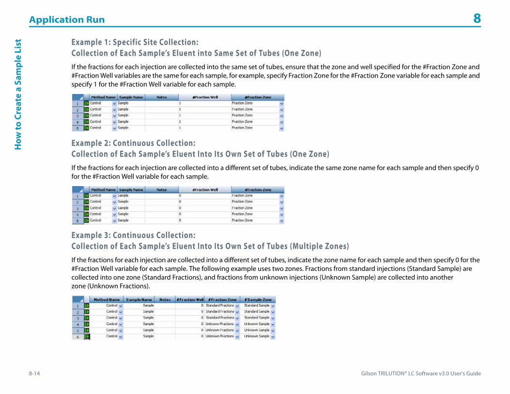
Application Run 8
8-14 Gilson TRILUTION® LC Software v3.0 User’s Guide
How
to C
reat
e a
Sam
ple
List Example 1: Specific Site Collection:
Collection of Each Sample’s Eluent into Same Set of Tubes (One Zone)If the fractions for each injection are collected into the same set of tubes, ensure that the zone and well specified for the #Fraction Zone and #Fraction Well variables are the same for each sample, for example, specify Fraction Zone for the #Fraction Zone variable for each sample and specify 1 for the #Fraction Well variable for each sample.
Example 2: Continuous Collection:Collection of Each Sample’s Eluent Into Its Own Set of Tubes (One Zone)If the fractions for each injection are collected into a different set of tubes, indicate the same zone name for each sample and then specify 0 for the #Fraction Well variable for each sample.
Example 3: Continuous Collection: Collection of Each Sample’s Eluent Into Its Own Set of Tubes (Multiple Zones)If the fractions for each injection are collected into a different set of tubes, indicate the zone name for each sample and then specify 0 for the #Fraction Well variable for each sample. The following example uses two zones. Fractions from standard injections (Standard Sample) are collected into one zone (Standard Fractions), and fractions from unknown injections (Unknown Sample) are collected into another zone (Unknown Fractions).

Gilson TRILUTION® LC Software v3.0 User’s Guide 8-15
Application Run 8H
ow to Create a Sam
pleList
How to Create a Sample List to Re-inject Collected Fractions
When setting up a sample list to re-inject collected fractions, use the Fraction Re-Injection ( ) button to access the Fraction Re-injection Criteria dialog.
To set up a sample list to re-inject collected fractions:
1 Set up the sample list for injections.
2 Click the Fraction Re-Injection ( ) button.3 Ensure that the Auto Re-injection check box is selected. (It is by default.)4 On the Fraction Re-injection Criteria dialog, specify the criteria for the fractions to re-inject. Do
this by specifying the minimum area of the fractions or the minimum height of the peaks. If both are specified, then both will be used.
5 Choose, by selecting the corresponding option button, whether to:• insert the fractions immediately after each parent or • after all parent samples (at end).
If you will be using a shutdown method, you can specify a step in the sample list for the shutdown and then the fractions will be inserted after all parent samples and before the shutdown. Refer to Select as Shutdown.
6 Select the method to execute when re-injecting the collected fractions. Note: The Sample Zone must be #Sample Zone and the Sample Well must be #Sample Well, defined in the Sample Variable dialog in this method.
7 If you wish to inject the fractions collected when your re-injection method was run, select the Apply Criteria to Re-Injected Fractions check box. It defaults cleared.
8 Optionally, set the minimum number of fraction sites required for each sample:
a) Click the Fraction Counter ( ) button.b) Enter the number of minimum fraction sites required for each sample.c) Click OK.

Application Run 8
8-16 Gilson TRILUTION® LC Software v3.0 User’s Guide
How
to C
reat
e a
Sam
ple
List Set Initial Volumes
For liquid tracking, click the Initial Volume ( ) button to access the Initial Volume Setting dialog.
To set initial volumes for any or all wells in each bed layout in the application:
1 Create the sample list. For more information, refer to How to Create a Sample List.
2 Click the Initial Volume ( ) button.3 Click to select a bed layout.4 Select a zone.5 Choose multiple well locations as described below.
• To select random wells, press the CTRL key and then select each well. • To select a range of wells, click and drag over a block of wells.
6 Right-click and then select Set Initial Volume. The Initial Volume dialog appears showing the default value of -1, indicating that an initial volume has not been set for the selected wells.
7 Type the initial volume and then click OK.8 Verify the entries in the grid.9 Repeat steps 4–8 for additional wells and/or repeat steps 3–8 for additional bed layouts.10 Click Close. The Initial Volume Confirmation dialog appears.
• Select Continue without setting Initial Volumes to 0 μL if you want volume tracking off for wells for which an initial volume was not specified. This is the default selection. For example, if you do not wish to track volumes in the rinse stations, select this option. Rinse volumes will not be tracked unless you specified an initial volume for the rinse station. Even if this option is selected, the Sample Tracking Report will report all aspirate and dispense volumes.
• Select Set initial volume of wells in selected zones to 0 μL if no initial volume was specified and then select the zones in which you wish track volumes in all wells.

Gilson TRILUTION® LC Software v3.0 User’s Guide 8-17
Application Run 8H
ow to Create a Sam
pleList
Clear Initial VolumesThere are several ways to clear initial volumes that have been set:• Select the rows, right-click, and then select Delete Row.• Click Clear Info. The grid is cleared.
Reset VolumesAs aspirations occur, the volumes in the tubes decrease. Volumes are not automatically reset between runs. To reset volumes to the set initial volumes, click Reset Volume.
View Delta VolumeDuring or after a run, information is available in this dialog about the initial volume that was set (Initial Volume), the current volume in the well (Current Volume), and the change in volume in the well (Delta Volume).

Application Run 8
8-18 Gilson TRILUTION® LC Software v3.0 User’s Guide
How
to E
xpor
t a S
ampl
eLi
st How to Export a Sample List1 On the Application Run window, click the Sample List Export ( ) button to display the Export window.2 In the Export window, select a folder, name the file, and then click Save. The sample list is saved in the specified folder with a .TSL extension.
Modify Sample List in Microsoft® Excel®1 After exporting the sample list, start Microsoft® Excel®.2 Click Open and then select to show Files of Type: All Files.3 Browse for and then select the .TSL file. Click Open.4 Click Next (accepting the default selections) on all import wizard screens that appear and then click Finish.
5 Make desired changes to values and descriptions only, and then save the modified Excel file by selecting Save from the File menu or by pressing CTRL + S. DO NOT select SAVE AS. When asked if you wish to keep the file in the current format, click Yes.When closing the file in Excel, you will be asked if you wish to save the file. Click No. It has already been saved in the desired format.
If additional columns appear in the sample list when it is opened in Excel, this is expected, however, DO NOT delete them.
Sample and Fraction Re-injection Criteria, Minimum Fraction Sites, and Initial Volumes cannot be modified in Excel.
Gilson TRILUTION® LC Software v3.0 User’s Guide 8-19
Application Run 8H
ow to Im
port a Sample
List
How to Import a Sample List1 On the Application Run window, click the Sample List Import ( ) button to display the Import window.2 On the Import window:
a) Browse for and then select the sample list file.b) Click Open.On completion of the Import operation, the information box appears and the imported sample list opens.
3 On the information dialog box:a) To view the log information of the import operation, click Details.b) Click OK.
View ResultsDuring the run, the software can generate data, reports (which may include chromatogram plots of acquired traces), and log. Refer to Chapter 11, Results for more information.
Because sample lists include information about the methods and the bed layout, sample lists that do not match the application cannot be imported.
Gilson TRILUTION® LC Software v3.0 User’s Guide 9-1
Running an Application 9
The Application Run window is where you start a run (refer to How to Start a Run) and monitor the progress of a run (refer to During a Run).
While the run is in progress, it is possible to:
• modify steps that have not yet been executed, which includes modifying a method. For more information, refer to Modify a Running Method.
• use the toolbar to manipulate the appearance of the run-time graph. For more information, refer to Chromatogram Toolbar.

Running an Application 9
9-2 Gilson TRILUTION® LC Software v3.0 User’s Guide
How
to S
tart
a Ru
n How to Start a RunTo get ready for and begin a run:
1 Make sure all system instruments are turned on and are ready to run (pumps are primed, column is equilibrated, samples are in place, etc.).
2 Check that the correct sample list is open.3 Click Run in the Application Run window.
If the data instrument is a 171 or 172 Diode Array Detector, ensure that the lamp is on.

Gilson TRILUTION® LC Software v3.0 User’s Guide 9-3
Running an Application 9D
uring a Run
During a RunWhen the run starts, you may want to focus your attention on the Application Run window, which includes:• Title Bar• Application Run Toolbar• Status Box• Run Time• Pause Time• Sample List Toolbar• Sample List Name• Sample List• Run Name• Maintenance Alarm Reminder• Method Configuration Toolbar• Chromatogram Tab• Chromatogram Toolbar• Bed Layout Tab• Mass Spec Spectra for Fractions Tab • Action Buttons• Info Window

Running an Application 9
9-4 Gilson TRILUTION® LC Software v3.0 User’s Guide
Dur
ing
a Ru
n Title BarThe title bar displays the name of the running application and the user name.
Application Run ToolbarClick an icon at the top of the Application Run window to perform the action described below.
Status BoxWhen the Application Run window is open, and throughout the run, a status box is displayed. The status box displays information for the instruments in the selected configuration. The following information is displayed here, if applicable: mobile phase flow rate, composition, and pressure, detector signal, contact state, make up pump flow rate and pressure, and MS detector status.
To view all of the information, hover the cursor over the status box. Information is displayed in the tool tip.
Run TimeThe Run Time field displays the time that has passed since the start of the current running method.
Run time may be paused, depending on the Sync task settings. For more information, refer to Sync on page A-389.
Icon Label Description
Manual ControlOpens the Manual Control window.
For more information, refer to Chapter 10, Manual HPLC System Control.
Manual AdvanceAvailable only when collecting fractions during a run.
Manually diverts the flow to waste, advances the fraction collector dispense head to the next well, and then resumes collection.
Divert Valve
Available only when collecting fractions during a run.
During collection, advances the fraction collector dispense head to the next well, and diverts the flow to waste. If the fraction collector is not collecting, flow continues to be diverted to waste. The software continues to monitor and will resume collection according to the method fraction collection parameters.
Show Graph in Cascade ModeAvailable only when collecting data during a run.
Creates a separate window for each data channel and cascades the windows.
Show Graph in Tiled ModeAvailable only when collecting data during a run.
Creates a separate window for each data channel and cascades the windows.
Gradient Hold
Available only during a run when a mobile phase pump is in the configuration.
Allows for temporarily changing the flow rate and ramping the mobile phase composition.
For more information, refer to How to Use a Gradient Hold.
Solvent SettingsAvailable only when a mobile phase pump is in the configuration.
Allows for indicating the volume of reservoir solvent. When the volume reaches 0, a notification is sent, if indicated in the Notification utility.
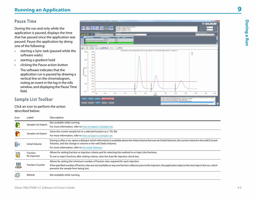
Gilson TRILUTION® LC Software v3.0 User’s Guide 9-5
Running an Application 9D
uring a Run
Pause TimeDuring the run and only while the application is paused, displays the time that has passed since the application was paused. Pause the application by doing one of the following:• starting a Sync task (paused while the
software waits)• starting a gradient hold• clicking the Pause action button
The software indicates that the application run is paused by drawing a vertical line on the chromatogram, noting an event in the log in the info window, and displaying the Pause Time field.
Sample List ToolbarClick an icon to perform the action described below:
Icon Label Description
Sample List ImportNot available while running.
For more information, refer to How to Import a Sample List.
Sample List ExportSaves the current sample list to a selected location as a .TSL file.
For more information, refer to How to Export a Sample List.
Initial VolumeDuring or after a run, opens a dialog in which information is available about the initial volume that was set (Initial Volume), the current volume in the well (Current Volume), and the change in volume in the well (Delta Volume).
For more information, refer to Set Initial Volumes.
Fraction Re-Injection
Allows for setting fraction re-injection criteria and for selecting the method to re-inject the fractions.
To not re-inject fractions after setting criteria, clear the Auto Re-injection check box.
Fraction CounterAllows for setting the minimum number of fraction sites required for each injection.
If the specified number of fraction sites are not available on any one fraction collector prior to the injection, the application skips to the next step in the run, which prevents the sample from being lost.
Refresh Not available while running.

Running an Application 9
9-6 Gilson TRILUTION® LC Software v3.0 User’s Guide
Dur
ing
a Ru
n Right-click MenuSelect a pending (not completed or running) row and then right-click to display the following options:
The following options are available after right-clicking on a pending sample:
Menu Description
Add Sample Adds a sample to the bottom of the sample list.
Add Multiple Samples Adds a user-specified number of samples to the bottom of the sample list.
Insert Sample Adds a sample between two existing samples.
Clear Sample Clears a sample row of all values, but keeps the row in the sample list.
Delete Sample Removes a sample from the sample list.
Paste Row Special Pastes a user-specified number of copies of the selected sample after the selected sample row.
Open Method Opens the method in the selected sample row in the Method Builder.
Select as ShutdownIdentifies the sample row in the sample list running an optional shutdown method.
For more information, refer to Specify a Shutdown.
Option Description
Functions as a resume or continue when a sample/step has been paused.
Select to skip the sample/step.
Select to pause the sample/step.
Right-click, and then select Run to run the sample/step.

Gilson TRILUTION® LC Software v3.0 User’s Guide 9-7
Running an Application 9D
uring a Run
Additional Copy/Paste OptionsThe sample list control in TRILUTION LC includes options for copying and incrementing within some columns and rows similar to spreadsheet programs. Refer to the following guidelines:
Copying/Incrementing within a Column• Only number values in number fields can be incremented. To increment the contents in a column, click in the first cell and drag down
through the cells to increment. The cursor displays as a plus sign (+) briefly on the right edge of the cell when the value can be incremented.
• To copy the contents of one cell to others in the same column, click in the cell with contents to be copied and then hold CTRL and drag down through the cells to which the contents should be copied. The cursor displays as a plus sign (+) briefly on the right edge of the cell when the value can be copied.
• Select the cell to be copied and then hold CTRL + C; select the destination cell and then hold CTRL + V. • Method Name selections cannot be copied within a column, alternatively, copy and paste the entire row.
Copying/Pasting a Row • Select the row to be copied and then hold CTRL + C; select the destination row and then hold CTRL + V.
• Select the row to be copied and then when the cursor changes ( ), drag and drop the row at the destination.
Sample List NameThe Sample List field displays the name of the open sample list.
Sample ListThe sample list is a list of steps to execute during a run. For information about creating a sample list, refer to How to Create a Sample List on page 8-13.
The current running step is highlighted green in the sample list; completed steps are grayed.
Run NameThe Run Name field displays the name of the run.

Running an Application 9
9-8 Gilson TRILUTION® LC Software v3.0 User’s Guide
Dur
ing
a Ru
n Maintenance Alarm ReminderA clock will be visible when accessing the Application Run window if an alarm is due soon. Hover the mouse over it or click to view a listing of the alarms due soon.
If an alarm is due or overdue, a yellow bar appears in the Application Run window informing that “Maintenance Alarms need attention. Click here.” Click the bar, select an alarm, and then click Done or Remind Me Later. If Remind Me Later was selected, the yellow bar will appear again the next day.
Method Configuration ToolbarNot available while running.

Gilson TRILUTION® LC Software v3.0 User’s Guide 9-9
Running an Application 9D
uring a Run
Chromatogram TabThe Chromatogram tab shows the run-time chromatographic plot of acquired data, gradient profile, and run-time events.
The trace begins at the data collection begin time (usually synchronized with injection).
For the gradient profile, the mobile phase composition (Y-axis—labeled % Mobile Phase) is plotted with respect to time (X-axis).
Chromatogram ToolbarThe chromatogram displays the real-time run data. Click an icon to perform the action described below. All settings are temporary and revert to the Graph Settings (refer to Graph or Normalized Graph on page 7-27) and Data Channel Settings on page 7-24 on the Method Builder-Analysis-Report Tab at the start of each sample.
Icon Description
Displays the print dialog for printing the chromatogram as it is currently viewed on-screen.
Copies the chromatogram, as it is currently viewed on-screen, to the clipboard.
Toggles between hiding and showing fraction collection start and stop lines.
Toggles between hiding and showing actual percent mobile phase.
Toggles between hiding and showing expected percent mobile phase.
Toggles showing or hiding the legend.
Scales both axes to minimum and maximum values for the displayed traces.
Scales the X-axis to minimum and maximum values for the displayed traces.
Scales Y-axis to minimum and maximum values for the displayed traces.
Returns view to last zoom (multiple undo zoom).
Returns view to next zoom (multiple redo zoom).
Zooms in on a point and centers it in the chromatogram as it is viewed on-screen.
Enlarges lassoed portion of the graph.

Running an Application 9
9-10 Gilson TRILUTION® LC Software v3.0 User’s Guide
Dur
ing
a Ru
n
Right-click Menu
Select the Move Channel tool ( ), and then right-click on a trace to display the following menu options:
Displays the time, signal level, and mobile phase composition at the intersect of the crosshair.
Moves one or more of the traces.
This option can be used to offset a chromatogram that is overlapping another. It can also be helpful when subtracting or dividing chromatograms because you can adjust for varying retention times by aligning peaks in the chromatogram.
Changes the color of the traces and mobile phase and allows you to choose to show or hide each.
Sets the lower limit, upper limit, increment value, and color for each axis.
Changes the orientation and color of the peak name labels and allows you to choose to show or hide the label.
Toggles showing or hiding the grid and allows you to change the color of the major (aligned with numbered tick marks) and/or minor (positioned between the numbered tick marks) grid lines.
Menu Description
Set Offset Displays the Channel Offset Settings dialog which allows you to change the color of the displayed trace and offset the trace in either the X (Minutes) or Y (mVolts) direction.
Set mVolts Offsets After moving the trace, this option provides an additional menu to zero the trace (Zero), return the trace to the previous setting (Last Setting), or revert to the original setting (Original Setting) in the Y-direction.
Set All mVolts Offsets After moving multiple traces, this option provides an additional menu to zero the traces (Zero), return the traces to the previous setting (Last Setting), or revert to the original settings (Original Setting) in the Y-direction.
Set Minutes Offsets After moving the trace, this option provides an additional menu to zero the trace (Zero), return the trace to the previous setting (Last Setting), or revert to the original setting (Original Setting) in the X-direction.
Set All Minutes Offsets After moving multiple traces, this option provides an additional menu to zero the traces (Zero), return the traces to the previous setting (Last Setting), or revert to the original settings (Original Setting) in the X-direction.
Move in Minutes Only Allows you to move the trace only horizontally.
Move in mVolts Only Allows you to move the trace only vertically.
Icon Description

Gilson TRILUTION® LC Software v3.0 User’s Guide 9-11
Running an Application 9D
uring a Run
Bed Layout TabWhen modifying a sample list, you can view the bed layout, select multiple wells, and have the software generate steps in the sample list.
1 Open the Application Run window.2 Select a method containing a well variable.3 Place the cursor in the first cell for which to select a
well.4 Click to select the Bed Layout tab.5 Select a bed layout and a zone from the drop-down
lists. Available wells appear in the zone’s active color.6 Choose multiple well locations as described below.
To select random wells within one zone:a) Press the CTRL key and then select each well.b) Click Add Single and all wells selected will be added as one row in the sample list or click Add Multiple and each well selected will be
added as its own row in the sample list.
To select a range of wells within one zone:a) Lasso the range of wells.b) Click Add Single and all wells selected will be added as one row in the sample list or click Add Multiple and each well selected will be
added as its own row in the sample list.Note: Zoom, if necessary. For more information, refer to Zoom on page L-12.
7 Review the sample list and, if necessary, enter or change the sample description for each sample.

Running an Application 9
9-12 Gilson TRILUTION® LC Software v3.0 User’s Guide
Dur
ing
a Ru
n Mass Spec Spectra for Fractions TabOn the Mass Spec Spectra for Fractions tab, the background subtracted mass spec fraction spectra is displayed as it is collected (if applicable).

Gilson TRILUTION® LC Software v3.0 User’s Guide 9-13
Running an Application 9D
uring a Run
Action ButtonsThe following action buttons are located in the lower left corner of the Application Run window.
Info WindowThe Info Window lists run-time events and the time each occurred. After the run, this information can be viewed in the log file. For more information, refer to View the Log File.
Action Button Description
Run/StopStarts the application run and changes the button text to Stop.
Click Stop to stop the run or simulation. You will be asked if you want to save data for the current sample. The mobile phase composition and flow conditions in effect at the time of termination remain in effect.
Pause/Resume
This option causes gradient progression and task execution to enter a timed hold. Mobile phase continues to flow at the composition and flow rate at the time of the pause; data collection and fraction collection continue. While paused, the Pause Time is displayed.
To continue the gradient progression and task execution, click Resume. Task execution resumes from the time of the pause. The gradient progression resumes at the composition and flow rate when the run was paused. The run time extends the duration of the pause. Pause Time is no longer displayed.
Stop Pump Not available while running.
Emergency Stop This option stops the run and stops the flow from the mobile phase pumps.
New Not available while running.
Open Not available while running.
Save Not available while running.
Save As Not available while running.
Delete Not available while running.
Running an Application 9
9-14 Gilson TRILUTION® LC Software v3.0 User’s Guide
Inte
rrup
t a R
un Interrupt a RunOptionally, pause or terminate a run in progress.
Pause a RunTo pause a run, click Pause.
Gradient progression and task execution enter a timed hold. Mobile phase continues to flow at the composition and flow rate at the time of the pause; data collection and fraction collection continue. The software indicates that the application run is paused by drawing a vertical line on the chromatogram, noting an event in the log in the info window, and displaying the Pause Time field.
To continue the gradient progression and task execution, click Resume. Task execution resumes from the time of the pause. The gradient progression resumes at the composition and flow rate when the run was paused. The run time extends the duration of the pause. Pause Time is no longer displayed.
Stop a RunTo stop the run, click Stop.
You will be asked if you want to save data for the current sample.
The mobile phase composition and flow conditions in effect at the time of termination remain in effect. Flow does not stop automatically after a run! To stop flow from the mobile phase pumps, click Stop Pump.
Emergency StopTo stop the run and stop the flow from the mobile phase pumps, click Emergency Stop.

Gilson TRILUTION® LC Software v3.0 User’s Guide 9-15
Running an Application 9H
ow to U
se a Gradient H
old
How to Use a Gradient HoldUsing a Gradient Hold allows for temporarily changing the flow rate and ramping the mobile phase composition.
1 Click .
2 In the Flow Rate box, type the desired total flow rate.3 In the Ramp Time box, type how long it should take to change from pumping at the current
concentrations to pumping at the concentrations listed below the Organic Hold Time.4 In the Organic Hold Time box, type the duration for maintaining those concentrations.5 In the Equilibration Ramp Time box, type how long it should take to change from pumping at
the concentrations listed below the Organic Hold Time to pumping at the concentrations listed in the box below the Equilibration Ramp Time (recommend that these concentrations are the same as those used in the running method).
6 Click OK. The application run is paused and a vertical line (labeled Hold Start) is drawn on the chromatogram, an event is noted in the log, and the Pause Time field appears.
7 When the gradient hold ends, the application run is paused and the following occur:• two vertical lines (one labeled Hold End and one labeled Pause) are drawn on the chromatogram• an event is noted in the log• the Pause Time field appears• the Gradient Hold Confirmation dialog appearsOn the Gradient Hold Confirmation dialog, do either of the following:• Select Resume current Sample to continue running the sample that was in process when the
gradient hold began. A vertical line (labeled Continue) is drawn on the chromatogram.• Select Skip to next Sample to save the data for the sample that was running when the
gradient hold began, but resume running with the next sample in the sample list.Click OK. The run resumes.

Running an Application 9
9-16 Gilson TRILUTION® LC Software v3.0 User’s Guide
Mod
ify a
Run
ning
Met
hod Modify a Running Method
A running method can be modified. Changes to the method will take effect on the next sample using that method.
To modify a running method:
1 Select the sample row, right-click, and then select Open Method.2 Modify, and then save the method.
Changes to the method will take effect on the next sample using that method in the sample list.3 Close the Method Builder.
Variables should not be added to a running method. (There is no way to refresh the sample list while running so that they can be used.)User Units and Data Channel Name cannot be changed in a running method.

Gilson TRILUTION® LC Software v3.0 User’s Guide 9-17
Running an Application 9A
fter a Run
After a RunA run is complete when the software has finished all of the samples in the sample list (or after clicking Stop or Emergency Stop).
The mobile phase composition and flow conditions in effect when the run is finished remain in effect. Flow does not stop automatically after a run! To stop flow from the mobile phase pumps, click Stop Pump.
Data and reports can be viewed, and stored data can be re-analyzed, using the Results window; refer to Chapter 11, Results.
If the run completes with errors, optionally check the log (refer to View the Log File) for the cause of the error.
If initial volumes were set, information about the change in volume per well can be viewed in the Initial Volume Setting dialog (click ). Information is provided about the initial volume that was set (Initial Volume), the current volume in the well (Current Volume), and the change in volume in the well (Delta Volume).
Shut Down the HPLC SystemShutdown methods are methods that include conditions that you want in effect after each run. A shutdown method might reduce the flow rate to zero and extinguish the lamp on a detector. You create shutdown methods as you would any method.
To shut down the HPLC system automatically at the end of a run, select the shutdown method for the last sample in the sample list.
Specify a ShutdownIf a shutdown method will be used, optionally specify a step in the sample list for the shutdown and then the fractions or samples for re-injection will be inserted after all parent samples and before the shutdown (if that option is selected).
To specify a shutdown:
1 Select a method under Method Name.2 Select the row.3 Right-click, and then select Select as Shutdown.
There is a red border around the shutdown method step number in the sample list.
Stop FlowClick Stop Pump to stop flow from the mobile phase pumps.

Running an Application 9
9-18 Gilson TRILUTION® LC Software v3.0 User’s Guide
Aft
er a
Run Log Off Automatically
To automatically end the current user’s session after a successfully completed run, ensure that it has been specified in the Settings.
View the Log FileTo display the log file produced during a run:
1 Access the Results dialog by right-clicking on an application in the Project Library and then selecting Results or by double-clicking the Results icon ( ).
2 Locate the run for which you want to view the log.3 Right-click on the run and then select View Log. The file appears in a text editor box. Optionally, add comments, change the font, and/or
print the log file. To save any changes, select File | Save As... (NOT Save).

Gilson TRILUTION® LC Software v3.0 User’s Guide 10-1
Manual HPLC System Control 10
In addition to application runs, the software provides manual control over HPLC system components. Manual control is useful for starting the system, method development, and checking HPLC system operation before a run.
Note: Before running your system in manual mode, be sure that instruments in the HPLC system are turned on and the appropriate connections are made as described in each user’s guide.
The key concept to understand about manual control is How to Manually Send Commands or Tasks to Instruments.

Manual HPLC System Control 10
10-2 Gilson TRILUTION® LC Software v3.0 User’s Guide
Man
ualC
ontr
olW
indo
w Manual Control Window
Manual control ( ) is accessed from the Application Run window.
The configuration selected on the Application Run window will be used in Manual Control.
The Manual Control window includes:• Toolbar• Task/Command List• List Tab• Chart Tab• Workspace• Action Buttons• Info Window
ToolbarClick an icon at the top of the Manual Control window to perform the action described below.
Icon Label Description
Manual Run Gradient
Sets the values for flow rate and mobile phase composition over a specified time (Ramp Time).
Not available while an application is running.
For more information, refer to Control of Mobile Phase Pumps.
Prime
Primes the syringe pump or the solvent system.
For a syringe pump, it aspirates the syringe capacity from the reservoir and then dispenses to the specified well in the specified zone for the number of cycles.
For a solvent system, it dispenses the transfer tubing capacity from the reservoir to the specified well in the specified zone for the number of cycles.

Gilson TRILUTION® LC Software v3.0 User’s Guide 10-3
Manual HPLC System Control 10M
anualControlWindow
Executing Toolbar FunctionsThe toolbar provides pre-defined command run lists on click of an icon.
To execute a pre-defined command run list:
1 Click the icon.2 Set the properties for the command or select the instrument for which to run the pre-defined command run list, when prompted.3 Click OK and the list runs.
Home Probes Homes the X/Y/Z on the specified liquid handler.
Home Pump Homes the solvent system or syringe pump at a specified well.
Auto Zero Channels Sets the signal for all channels on the selected 15X Detector and/or 506 System Interface to 0.
Icon Label Description

Manual HPLC System Control 10
10-4 Gilson TRILUTION® LC Software v3.0 User’s Guide
Man
ualC
ontr
olW
indo
w Task/Command ListThe Task/Command list displays sorted tasks and commands that can be added to the list for running in manual control.
One default group (Auxiliary) exists for every method. Auxiliary tasks are not specific to any instrument.
All other tasks are listed alphanumerically under the instrument name.
Commands are listed alphanumerically under the instrument type.
For descriptions of Gilson-supplied tasks, refer to Appendix A, List of Tasks.
For descriptions of the commands, refer to Appendix E, List of Commands.
List TabIf viewing the Chart tab, click to return to the List Tab.
Chart TabClick to display the strip chart for one, two, or several data channels.
For more information, refer to Strip Chart Control.
Chart ToolbarClick an icon to perform the action described below.
Icon Label Description
Print. Displays the print dialog for printing the chromatogram as it is currently viewed on-screen.
Copy to clipboard. Copies the chromatogram, as it is currently viewed on-screen, to the clipboard.
Show/Hide Legend. Toggles showing or hiding the legend.
Set auto scale. Scales both axes to minimum and maximum values for the displayed traces.
Set X axis to auto scale. Scales the X-axis to minimum and maximum values for the displayed traces.
Set Y axis to auto scale. Scales Y-axis to minimum and maximum values for the displayed traces.
Return to previous zoomed parameters. Returns view to last zoom (multiple undo zoom).

Gilson TRILUTION® LC Software v3.0 User’s Guide 10-5
Manual HPLC System Control 10M
anualControlWindow
Right-click Menu
Select the Move Channel tool ( ) and then right-click on a trace to display the following menu options:
Return to next zoomed parameters. Returns view to next zoom (multiple redo zoom).
Select point zoom tool. Zooms in on a point and centers it in the chromatogram as it is viewed on-screen.
Select lasso zoom tool. Enlarges lassoed portion of the graph.
Select cross hair tool. Displays the time, signal level, and mobile phase composition at the intersect of the crosshair.
.Select move channel tool.Moves one or more of the traces.
This option can be used to offset a chromatogram that is overlapping another. It can also be helpful when subtracting or dividing chromatograms because you can adjust for varying retention times by aligning peaks in the chromatogram.
Channel Attributes Changes the color of the traces and mobile phase and allows you to choose to show or hide each.
Axis Attributes. Sets the lower limit, upper limit, increment value, and color for each axis.
Grid Attributes. Toggles showing or hiding the grid and allows you to change the color of the major (aligned with numbered tick marks) and/or minor (positioned between the numbered tick marks) grid lines.
Menu Description
Set Offset Displays the Channel Offset Settings dialog which allows you to change the color of the displayed trace and offset the trace in either the X (Minutes) or Y (mVolts) direction.
Set mVolts Offsets After moving the trace, this option provides an additional menu to zero the trace (Zero), return the trace to the previous setting (Last Setting), or revert to the original setting (Original Setting) in the Y-direction.
Set All mVolts Offsets After moving multiple traces, this option provides an additional menu to zero the traces (Zero), return the traces to the previous setting (Last Setting), or revert to the original settings (Original Setting) in the Y-direction.
Set Minutes Offsets After moving the trace, this option provides an additional menu to zero the trace (Zero), return the trace to the previous setting (Last Setting), or revert to the original setting (Original Setting) in the X-direction.
Set All Minutes Offsets After moving multiple traces, this option provides an additional menu to zero the traces (Zero), return the traces to the previous setting (Last Setting), or revert to the original settings (Original Setting) in the X-direction.
Move in Minutes Only Allows you to move the trace only horizontally.
Move in mVolts Only Allows you to move the trace only vertically.
Icon Label Description

Manual HPLC System Control 10
10-6 Gilson TRILUTION® LC Software v3.0 User’s Guide
Man
ualC
ontr
olW
indo
w WorkspaceBuild manual run lists in the workspace.
For more information, refer to How to Manually Send Commands or Tasks to Instruments.
Right-click MenuRight-click on a task or command in the workspace to display the following menu options:
Action ButtonsThe following action buttons are located in the lower left corner of the Manual Control window.
Info WindowThe info window lists each command and the time it was executed.
Menu Description
Properties Select to edit the properties for the task or command.
Remove Deletes the selected command from the run list.
Copy to Task Builder Copies the selected tasks or commands to the clipboard for pasting in the Task Builder.
Action Button Description
Run/StopExecutes the commands in the run list. For more information, refer to How to Manually Send Commands or Tasks to Instruments.
To stop the run, click Stop. The mobile phase composition and flow conditions in effect at the time of termination remain in effect. Data collection and pumping does not stop.
Stop Pump This option stops flow from the mobile phase pumps. It is only available until the run starts.

Gilson TRILUTION® LC Software v3.0 User’s Guide 10-7
Manual HPLC System Control 10Control of M
obilePhase Pum
ps
Control of Mobile Phase PumpsValues for flow rate and mobile phase composition over a specified ramp time can be set using manual control:
1 On the Manual Control window, click the Gradient button ( ).2 In the Flow Rate box, type the desired flow rate.3 In the Ramp Time box, type the ramp time over which to achieve the desired conditions.4 For each pump, type the desired percent composition from that pump in the Concentration %
field.5 After specifying all parameters, click OK.
Strip Chart ControlThe Chart tab in the Manual Control window allows for starting and stopping data collection and viewing a strip chart for one, two, or several data channels.
1 Click the Chart tab on the Manual Control window.2 Click Start Data Collection to begin viewing data from all UV/VIS channels or click Start Mass Spec Scan to begin viewing data from
Flexar SQ 300 MS Detector Channel 1. The traces for the channel(s) appear in the window.3 Data collection continues until you click Stop Data Collection or Stop Mass Spec Scan. When data collection is halted, a dialog box appears
that enables you to save the collected data.If you select to save the strip chart, it is stored with other run results. (Refer to Chapter 11, Results.) The software indicates in the Info Window that the result is a manual result (Manual Result: Yes).
Manual HPLC System Control 10
10-8 Gilson TRILUTION® LC Software v3.0 User’s Guide
How
to M
anua
lly S
end
Com
man
ds o
r Tas
ks to
Inst
rum
ents How to Manually Send Commands or Tasks to Instruments
During manual control, you can send instructions to the instruments in the selected configuration.
To issue a command or task to one of these instruments:
1 From the Task/Command List, drag and then drop a command or task into the workspace. After adding a custom task to the workspace, you will be asked if you want to update the task defaults. Click Yes and the values specified for the parameters will be remembered the next time this task is used. Click No and property changes will only affect the current manual control session.For a description of the commands, refer to Appendix E, List of Commands.For a description of the tasks, refer to Appendix A, List of Tasks.
2 Set the properties.3 Continue adding commands or tasks, or click Run.
Reorder Commands or TasksTo change the order in which commands or tasks are executed, select the command or task and then click the up ( ) or down ( ) arrow.
To change which commands or tasks are executed, select or clear the check box next to the command or task name in the run list.
Remove Commands or TasksTo remove commands or tasks:
1 Select the command or task in the workspace.2 Right-click, and then select Remove or press the DELETE key.
Data StorageDuring a manual run, the software can generate data. Refer to Chapter 11, Results for more information.

Gilson TRILUTION® LC Software v3.0 User’s Guide 11-1
Results 11
The Run Results window enables viewing chromatogram plots and analysis information for collected data.
From a run, the software produces Results containing the channel data collected and stored for all injected samples. Results contain time and signal information for each sample.
To view results of data analysis, open the analysis report.
Right-click on an application in the Project Library and then select Results or double-click the results icon ( ) to display the Results window.
Key concepts to understand about results are:
• How to View Results
• How to Export Results
• How to Archive Results
• How to Restore Results
• How to View Spectral Data
• How to View Run Results
• How to Analyze Data in a Different Way

Results 11
11-2 Gilson TRILUTION® LC Software v3.0 User’s Guide
Resu
lts
Win
dow Results Window
The Results window displays all runs for the application. The exception is when runs have been archived, in which case they must be restored to be viewed.
The Results window includes:• Results Tab• Summary Tab• Calibration Tab• Tune/Diagnostics Tab• Toolbar• Action Buttons
Results TabDouble-click the run name to show the run results. For more information, refer to How to View Run Results.
Right-click MenuSelect a run, and then right-click for the following options:
To sort the run results, click on a column header. To sort in reverse order, click the column header again.
Menu Description
Open Result Displays stored collected data. Information for all samples injected during the run is stored here.
Rename Run Allows for assigning a different name to a run.
ExportCopies the run (data and method) to a specified external location (i.e., network drive) as a Result Export File (.LCRA).
For more information, refer to How to Export Results.
Archive
Moves the run (data and method) to a specified external location (i.e., network drive) as a Result Export File (.LCRA).
The difference between Export and Archive is that Export leaves data in the Results dialog, whereas Archive removes it. Both allow the data to be restored.
For more information, refer to How to Archive Results.
Delete Permanently deletes the run data.
View Log Opens the log file, which is detailed information obtained during the run and shown in the info window, in Microsoft® Notepad.
View Diagnostics Opens a dialog for selecting a sample for which to view the diagnostics for the Flexar SQ 300 MS Detector as recorded at the beginning of each sample in the application run.
Extract Methods Displays the methods (and any error methods) used to generate the results in an Extract Methods dialog. Optionally, select methods to import (by default, all are selected), and then click OK. Extracted methods import into the application in which they were run.
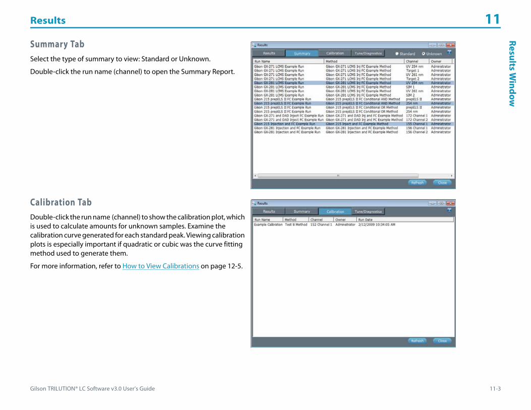
Gilson TRILUTION® LC Software v3.0 User’s Guide 11-3
Results 11Results W
indow
Summary TabSelect the type of summary to view: Standard or Unknown.
Double-click the run name (channel) to open the Summary Report.
Calibration TabDouble-click the run name (channel) to show the calibration plot, which is used to calculate amounts for unknown samples. Examine the calibration curve generated for each standard peak. Viewing calibration plots is especially important if quadratic or cubic was the curve fitting method used to generate them.
For more information, refer to How to View Calibrations on page 12-5.
Results 11
11-4 Gilson TRILUTION® LC Software v3.0 User’s Guide
Resu
lts
Win
dow Tune/Diagnostics Tab
This tab is only accessible after running an Auto Tune, Check Tune or a Diagnostics report.
Double-click the type of log to view (Auto Tune or Check Tune) or a Diagnostics report.
Right-click MenuSelect a log or Diagnostics, and then right-click for the following options:
View Auto TuneProvides options for viewing, saving or printing an Auto Tune Log and/or Check Tune Results. Saved logs and results are saved to a user-specified location as .HTML files.
Auto Tune Log
Displays the log that was generated during the auto tune/check tune.
Check Tune Results
Displays the results of the check tune that was run automatically after the auto tune.
If any failures for Mass or Width are indicated, first verify the following and then auto tune again:• Was the correct tune mix source selected and is there enough tune mix available?• Are the lines primed?• Are there any leaks in the fittings for the tune mix or nitrogen supply connections?• Is the dry gas flow at 8000 mL/min? Is the dry gas temperature at 300°C? Is the nebulizer gas pressure at 80 psi? (Run the diagnostics or
check the status box in the Application Run window.)
Menu Description
ArchiveMoves the log to a specified external location (i.e., network drive) as a Diagnostic Export File (.LCDT).
The difference between Export and Archive is that Export leaves the log in the dialog, whereas Archive removes it. Both allow the log to be restored.
Delete Permanently deletes the log.
Export Copies the log to a specified external location (i.e., network drive) as a Diagnostic Export File (.LCDT).
Import Imports a .LCDT file.
ViewOpens the log file, which is detailed information obtained during the run and shown in the info window, in Microsoft® Notepad. Also provides options for viewing tune results or diagnostics for the Flexar SQ 300 MS detector.
For more information, refer to View Auto Tune, View Check Tune, and/or View Diagnostics.

Gilson TRILUTION® LC Software v3.0 User’s Guide 11-5
Results 11Results W
indow
View Check TuneProvides options for viewing, saving or printing a Check Tune Log and/or Check Tune Results. Saved logs and results are saved to a user-specified location as .HTML files.
Check Tune Log
Displays the log that was generated during the check tune.
Check Tune Results
Displays the results of the check tune. If any failures for Mass or Width are indicated, run an auto tune.
View DiagnosticsProvides options for viewing, saving or printing a diagnostics report. Saved diagnostic reports are saved to a user-specified location as .HTML files.
Short Diagnostics
Displays run-critical diagnostics.
All Current Values
Displays the actual values at the time requested for all diagnostic parameters.
All Diagnostics
Displays values entered and actual values for all diagnostic parameters.

Results 11
11-6 Gilson TRILUTION® LC Software v3.0 User’s Guide
Resu
lts
Win
dow Toolbar
Click an icon to perform the action described below.
Action ButtonsThe following action buttons are located in the lower right corner of the Results window.
Icon Description
Lists run results based on the filter selected.
When filtering by peak names, separate multiple peak names by % and list them in the order that they elute from the column.
Copies the run (data and methods) to a specified external location (i.e., network drive) as a Result Export File (.LCRA).
For more information, refer to How to Export Results.
Moves the run (data and methods) to a specified external location (i.e., network drive) as a Result Export File (.LCRA).
The difference between Export and Archive is that Export leaves data in the Results dialog, whereas Archive removes it. Both allow the data to be restored.
For more information, refer to How to Archive Results.
Imports a Results Export File (.LCRA) and lists the run results in the Results window.
For more information, refer to How to Restore Results.
Action Button Description
Refresh Reloads the window with any new or imported run results.
Close Exits the Results window.

Gilson TRILUTION® LC Software v3.0 User’s Guide 11-7
Results 11H
ow to View
Results
How to View ResultsTo view results:
1 Right-click on an application in the Project Library and then select Results or double-click the results icon ( ) to display the Results window.2 Double-click the run name to display the result in the Run Results window.
For information about how to view the run results in the Run Results window, refer to How to View Run Results.
How to Export Results1 On the Results window, select the run name, and then do either of the following:
• Right-click, and then select Export.• Click .
2 Select a folder, and then click OK. On completion of the export operation, the run results and the embedded methods and tasks and diagnostics, but not sample list are saved in the specified folder with a .LCRA extension.
3 When the export success/fail dialog appears:• Click Details to view the log information of the export operation.• Click OK.
How to Archive ResultsArchive run data before deleting applications.
1 On the Results window, select the run name, and then do either of the following:• Right-click, and then select Archive.• Click .
2 Select a folder, and then click OK. On completion of the archive operation, the run results and the embedded methods and tasks and diagnostics (if applicable), but not sample list, are moved to the specified folder with a .LCRA extension.
3 When the archive success/fail dialog appears:• Click Details to view the log information of the archive operation.• Click OK.
The difference between export and archive is that export leaves data in the Results window, whereas archive removes it. Both allow the data to be restored.
Results 11
11-8 Gilson TRILUTION® LC Software v3.0 User’s Guide
How
to R
esto
re R
esul
ts How to Restore ResultsRestore runs that have been exported or archived.
1 On the Results window, click to display the Import window.2 From the Import window:
a) Browse for and select one or more Result Export Files (.LCRA).b) Click Open.
3 When the import success/fail dialog appears:• Click Details to view the log information of the import (restore) operation.• Click OK.
How to Delete ResultsRun data can be permanently deleted.
1 On the Results window, select the run name, right-click, and then select Delete.2 On the Delete confirmation box, click Yes. The run data is permanently deleted.
Methods are not automatically imported or restored with results. To access the methods, right-click on the run name in the Results window and then select Extract Methods. For more information, refer to Results Tab.
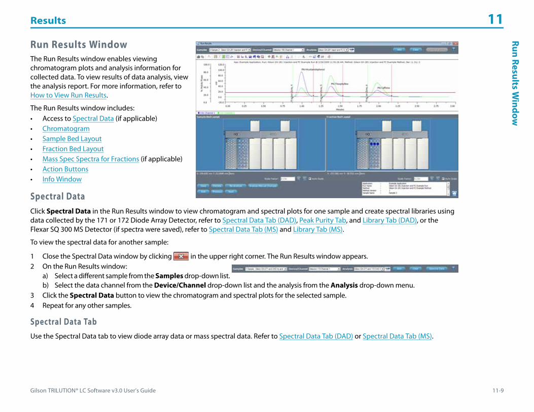
Gilson TRILUTION® LC Software v3.0 User’s Guide 11-9
Results 11Run Results W
indow
Run Results WindowThe Run Results window enables viewing chromatogram plots and analysis information for collected data. To view results of data analysis, view the analysis report. For more information, refer to How to View Run Results.
The Run Results window includes:• Access to Spectral Data (if applicable)• Chromatogram• Sample Bed Layout• Fraction Bed Layout• Mass Spec Spectra for Fractions (if applicable)• Action Buttons• Info Window
Spectral DataClick Spectral Data in the Run Results window to view chromatogram and spectral plots for one sample and create spectral libraries using data collected by the 171 or 172 Diode Array Detector, refer to Spectral Data Tab (DAD), Peak Purity Tab, and Library Tab (DAD), or the Flexar SQ 300 MS Detector (if spectra were saved), refer to Spectral Data Tab (MS) and Library Tab (MS).
To view the spectral data for another sample:
1 Close the Spectral Data window by clicking in the upper right corner. The Run Results window appears.2 On the Run Results window:
a) Select a different sample from the Samples drop-down list.b) Select the data channel from the Device/Channel drop-down list and the analysis from the Analysis drop-down menu.
3 Click the Spectral Data button to view the chromatogram and spectral plots for the selected sample.4 Repeat for any other samples.
Spectral Data TabUse the Spectral Data tab to view diode array data or mass spectral data. Refer to Spectral Data Tab (DAD) or Spectral Data Tab (MS).

Results 11
11-10 Gilson TRILUTION® LC Software v3.0 User’s Guide
Run
Resu
lts
Win
dow Spectral Data Tab (DAD)
Use the Spectral Data tab to view diode array data.
By default, a 3D plot of the spectral data set, a spectrum plot of the first named peak (in the peak table) or the first integrated peak found (if no peaks were named in the peak table) at the APEX, and the chromatogram are displayed.
The Spectral Data Tab (DAD) includes:• Spectral Data Tab (DAD) - 3D Plot/Iso-electric Plot• Spectral Data Tab (DAD) - Chromatogram• Spectral Data Tab (DAD) - Spectrum Plot

Gilson TRILUTION® LC Software v3.0 User’s Guide 11-11
Results 11Run Results W
indow
Spectral Data Tab (DAD) - 3D Plot/Iso-electric Plot
Zoom (3D Plot)
To zoom toward the center of the plot, right-click while dragging the mouse downward.
To zoom away from the center of the plot, right-click while dragging the mouse upward.
Zoom (Iso-electric Plot)
To zoom in, right-click on the plot.
To zoom out, right-click outside the plot on either axis.
Toolbar
Click an icon to perform the action described below:
Icon Label Description
Show 3D plot Displays the 3D plot.
Show iso-electric plot Displays the iso-electric plot.
Show continuous Displays the plot using a continuous color scheme, which provides the best on-screen display.
Show stepped intervals Displays the plot using a stepped interval color scheme, which redraws quickest.
Show grayscale Displays the plot using a grayscale color scheme, which shows how a black and white printout of the plot would look.
Select crosshair toolDisplays the Time, Wavelength, and Absorbance at the intersect of the crosshair when the iso-electric plot is displayed.
Click on the iso-electric plot to update the wavelength on the chromatogram and the retention time on the spectrum.
Print Displays the print dialog for printing the plot as it is currently viewed on-screen.
Copy to clipboard Copies the plot, as it is currently viewed on-screen, to the clipboard.

Results 11
11-12 Gilson TRILUTION® LC Software v3.0 User’s Guide
Run
Resu
lts
Win
dow Right-click Menu
Right-click next to the toolbar then select Control Panel to access the following options for the 3D plot:
Spectral Data Tab (DAD) - Chromatogram
Shows the chromatogram plot for the selected data channel and analysis. Optionally shows an overlaid data trace at a user-selected wavelength (using the cross hair tool on the iso-electric plot or Settings button).
Settings
Click the Settings button and then modify any or all of the parameters. After clicking OK, the chromatogram shows an overlaid data trace to reflect those settings.
Option Description
Elevation Angle The default is 20.0 degrees. This parameter modifies the angle of the Z axis in relation to the X axis. Setting a smaller number causes the 3D view to tilt away from you. Setting a larger number causes the 3D view to tilt towards you.
Azimuth Angle The default is -34.5 degrees. Setting a larger angle causes the traces to become more stacked. Setting a smaller angle causes the traces to appear farther apart.
View RadiusThe default is 5.0; the valid range for this parameter is 1 to 10. Setting a smaller radius makes the plot larger. Setting a larger radius makes the plot smaller.
View Radius is calculated as follows: Wavelength x Time x AU
Angular Width The default is 50 degrees. Setting a larger width makes the plot smaller. Setting a smaller width makes the plot larger.
Defaults Click to return the options to their default settings.
Apply Click to accept the selected options and apply them to the plot.
Legend Identifies the absorbance range associated with each color or pattern.

Gilson TRILUTION® LC Software v3.0 User’s Guide 11-13
Results 11Run Results W
indow
Toolbar
Click an icon to perform the action described below:
Icon Label Description
Print. Displays the print dialog for printing the chromatogram as it is currently viewed on-screen.
Copy to clipboard. Copies the chromatogram, as it is currently viewed on-screen, to the clipboard.
Show/Hide Legend. Toggles showing or hiding the legend.
Set auto scale. Scales both axes to minimum and maximum values for the displayed traces.
Set X axis to auto scale. Scales the X-axis to minimum and maximum values for the displayed traces.
Set Y axis to auto scale. Scales Y-axis to minimum and maximum values for the displayed traces.
Return to previous zoomed parameters. Returns view to last zoom (multiple undo zoom).
Return to next zoomed parameters. Returns view to next zoom (multiple redo zoom).
Select point zoom tool. Zooms in on a point and centers it in the chromatogram as it is viewed on-screen.
Select lasso zoom tool. Enlarges lassoed portion of the graph.
Select cross hair tool. Displays the minutes and absorbance at the intersect of the crosshair.
Select move channel tool.Moves one or more of the traces.
This option can be used to offset a chromatogram that is overlapping another. It can also be helpful when subtracting or dividing chromatograms because you can adjust for varying retention times by aligning peaks in the chromatogram.
Channel Attributes Changes the color of the trace allows you to choose to show or hide.
Axis Attributes. Sets the lower limit, upper limit, increment value, and color for each axis.
Peak Label Attributes. Changes the orientation and color of the peak name labels and allows you to choose to show or hide the labels.
Grid Attributes. Toggles showing or hiding the grid and allows you to change the color of the major (aligned with numbered tick marks) and/or minor (positioned between the numbered tick marks) grid lines.

Results 11
11-14 Gilson TRILUTION® LC Software v3.0 User’s Guide
Run
Resu
lts
Win
dow Right-click Menu
Right-click on the chromatogram to access the following options:
Select the Move Channel tool ( ) and then right-click on a trace to display the following menu options:
Option Description
Point zoom Zooms in on a point and centers it in the chromatogram as it is viewed on-screen.
Lasso zoom Enlarges lassoed portion of the graph.
Cross hairs Displays the minutes and absorbance at the intersect of the crosshair.
Move channelMoves one or more of the traces.
This option can be used to offset a chromatogram that is overlapping another. It can also be helpful when subtracting or dividing chromatograms because you can adjust for varying retention times by aligning peaks in the chromatogram.
Menu Description
Set Offset Displays the Channel Offset Settings dialog which allows you to change the color of the displayed trace and offset the trace in either the X (Minutes) or Y (mVolts) direction.
Set mVolts Offsets After moving the trace, this option provides an additional menu to zero the trace (Zero), return the trace to the previous setting (Last Setting), or revert to the original setting (Original Setting) in the Y-direction.
Set All mVolts Offsets After moving multiple traces, this option provides an additional menu to zero the traces (Zero), return the traces to the previous setting (Last Setting), or revert to the original settings (Original Setting) in the Y-direction.
Set Minutes Offsets After moving the trace, this option provides an additional menu to zero the trace (Zero), return the trace to the previous setting (Last Setting), or revert to the original setting (Original Setting) in the X-direction.
Set All Minutes Offsets After moving multiple traces, this option provides an additional menu to zero the traces (Zero), return the traces to the previous setting (Last Setting), or revert to the original settings (Original Setting) in the X-direction.
Move in Minutes Only Allows you to move the trace only horizontally.
Move in mVolts Only Allows you to move the trace only vertically.
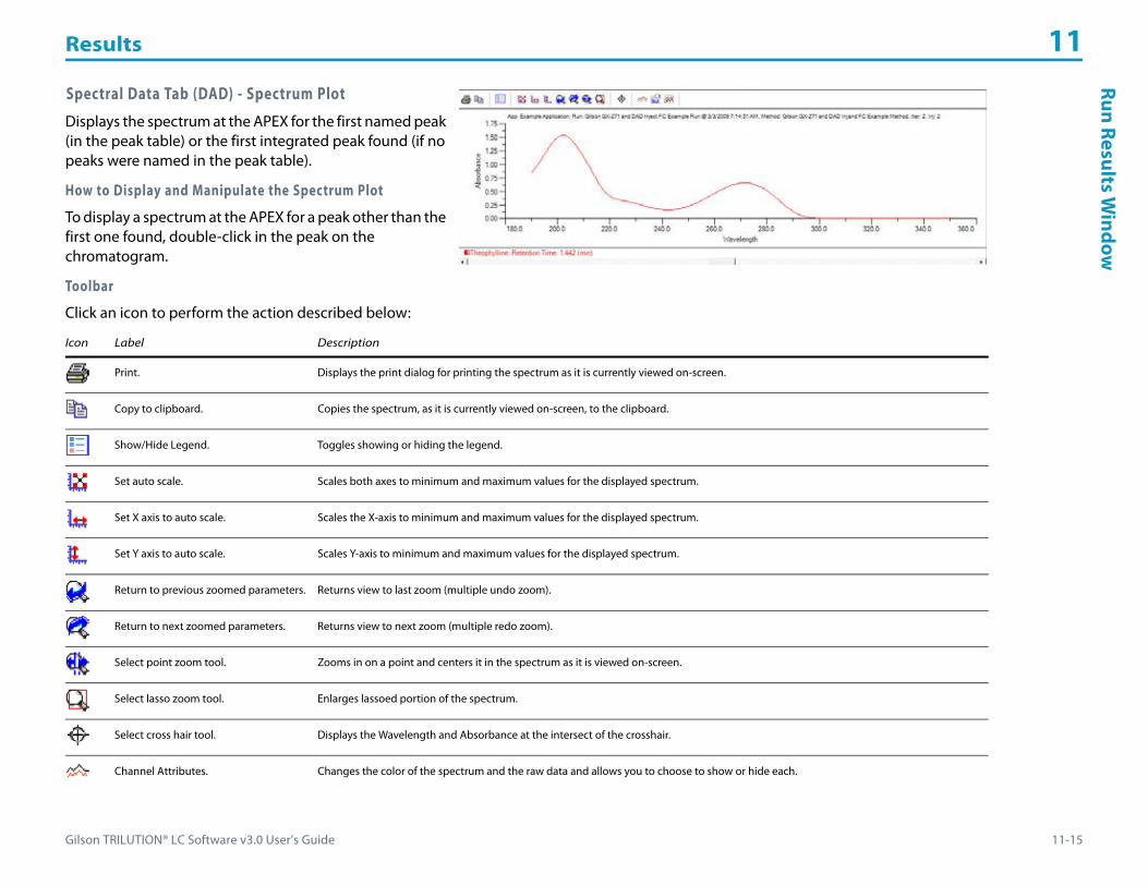
Gilson TRILUTION® LC Software v3.0 User’s Guide 11-15
Results 11Run Results W
indow
Spectral Data Tab (DAD) - Spectrum Plot
Displays the spectrum at the APEX for the first named peak (in the peak table) or the first integrated peak found (if no peaks were named in the peak table).
How to Display and Manipulate the Spectrum Plot
To display a spectrum at the APEX for a peak other than the first one found, double-click in the peak on the chromatogram.
Toolbar
Click an icon to perform the action described below:
Icon Label Description
Print. Displays the print dialog for printing the spectrum as it is currently viewed on-screen.
Copy to clipboard. Copies the spectrum, as it is currently viewed on-screen, to the clipboard.
Show/Hide Legend. Toggles showing or hiding the legend.
Set auto scale. Scales both axes to minimum and maximum values for the displayed spectrum.
Set X axis to auto scale. Scales the X-axis to minimum and maximum values for the displayed spectrum.
Set Y axis to auto scale. Scales Y-axis to minimum and maximum values for the displayed spectrum.
Return to previous zoomed parameters. Returns view to last zoom (multiple undo zoom).
Return to next zoomed parameters. Returns view to next zoom (multiple redo zoom).
Select point zoom tool. Zooms in on a point and centers it in the spectrum as it is viewed on-screen.
Select lasso zoom tool. Enlarges lassoed portion of the spectrum.
Select cross hair tool. Displays the Wavelength and Absorbance at the intersect of the crosshair.
Channel Attributes. Changes the color of the spectrum and the raw data and allows you to choose to show or hide each.
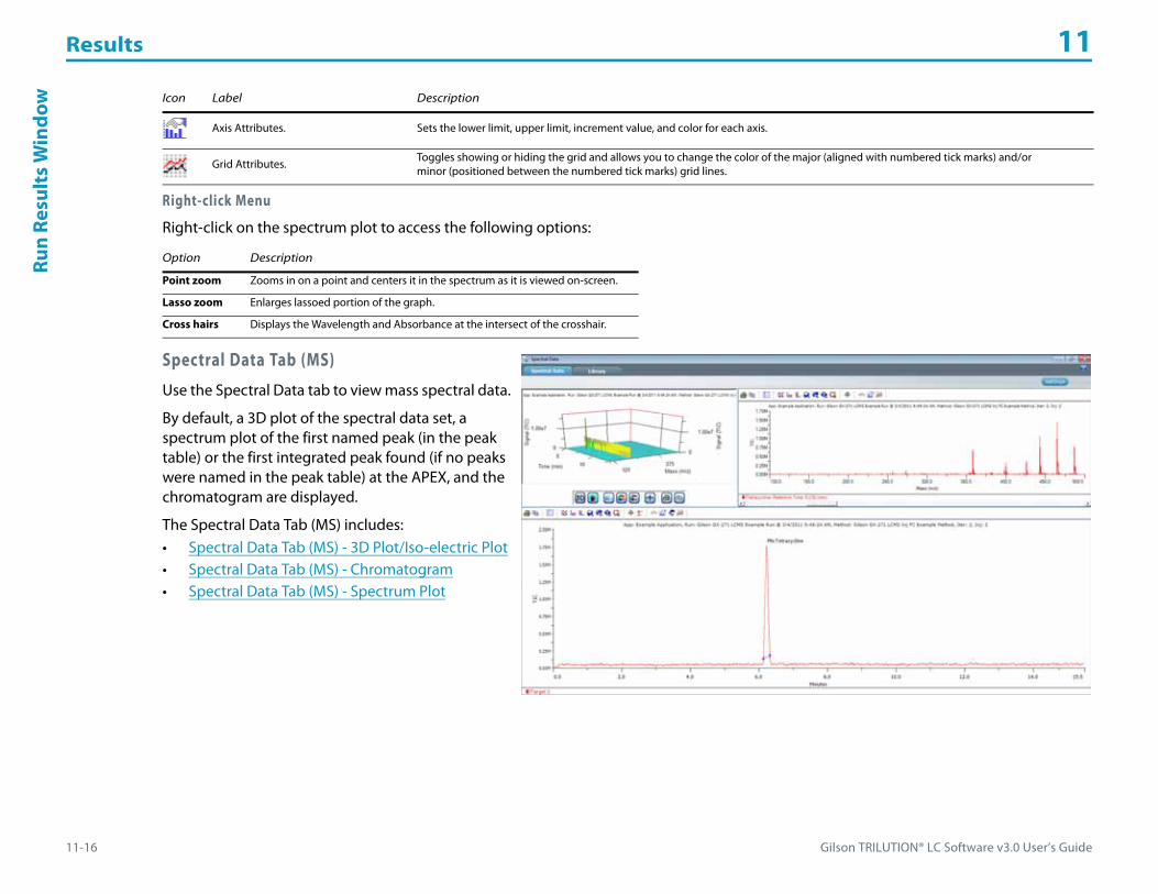
Results 11
11-16 Gilson TRILUTION® LC Software v3.0 User’s Guide
Run
Resu
lts
Win
dow
Right-click Menu
Right-click on the spectrum plot to access the following options:
Spectral Data Tab (MS)
Use the Spectral Data tab to view mass spectral data.
By default, a 3D plot of the spectral data set, a spectrum plot of the first named peak (in the peak table) or the first integrated peak found (if no peaks were named in the peak table) at the APEX, and the chromatogram are displayed.
The Spectral Data Tab (MS) includes:• Spectral Data Tab (MS) - 3D Plot/Iso-electric Plot• Spectral Data Tab (MS) - Chromatogram• Spectral Data Tab (MS) - Spectrum Plot
Axis Attributes. Sets the lower limit, upper limit, increment value, and color for each axis.
Grid Attributes. Toggles showing or hiding the grid and allows you to change the color of the major (aligned with numbered tick marks) and/or minor (positioned between the numbered tick marks) grid lines.
Option Description
Point zoom Zooms in on a point and centers it in the spectrum as it is viewed on-screen.
Lasso zoom Enlarges lassoed portion of the graph.
Cross hairs Displays the Wavelength and Absorbance at the intersect of the crosshair.
Icon Label Description
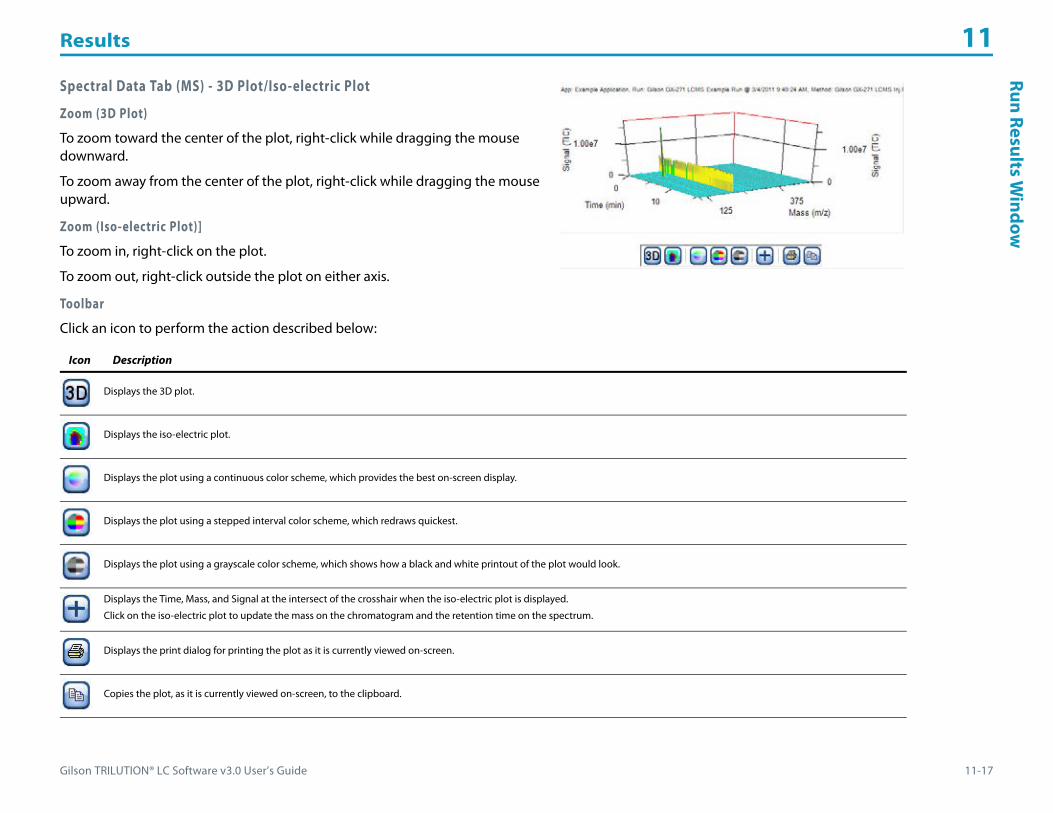
Gilson TRILUTION® LC Software v3.0 User’s Guide 11-17
Results 11Run Results W
indow
Spectral Data Tab (MS) - 3D Plot/Iso-electric Plot
Zoom (3D Plot)
To zoom toward the center of the plot, right-click while dragging the mouse downward.
To zoom away from the center of the plot, right-click while dragging the mouse upward.
Zoom (Iso-electric Plot)]
To zoom in, right-click on the plot.
To zoom out, right-click outside the plot on either axis.
Toolbar
Click an icon to perform the action described below:
Icon Description
Displays the 3D plot.
Displays the iso-electric plot.
Displays the plot using a continuous color scheme, which provides the best on-screen display.
Displays the plot using a stepped interval color scheme, which redraws quickest.
Displays the plot using a grayscale color scheme, which shows how a black and white printout of the plot would look.
Displays the Time, Mass, and Signal at the intersect of the crosshair when the iso-electric plot is displayed.
Click on the iso-electric plot to update the mass on the chromatogram and the retention time on the spectrum.
Displays the print dialog for printing the plot as it is currently viewed on-screen.
Copies the plot, as it is currently viewed on-screen, to the clipboard.

Results 11
11-18 Gilson TRILUTION® LC Software v3.0 User’s Guide
Run
Resu
lts
Win
dow Right-click Menu
Right-click next to the toolbar then select Control Panel to access the following options for the 3D plot:
Spectral Data Tab (MS) - Chromatogram
Shows the chromatogram plot for the selected data channel and analysis. Optionally shows an overlaid data trace at a user-selected mass (using the cross hair tool on the iso-electric plot or Settings button). Optionally, hide the selected data channel for better viewing of the overlaid data trace.
Settings
Click the Settings button and then enter a mass (m/z). After clicking OK, the chromatogram shows an overlaid data trace for that mass.
Option Description
Elevation Angle This parameter modifies the angle of the Z axis in relation to the X axis. Setting a smaller number causes the 3D view to tilt away from you. Setting a larger number causes the 3D view to tilt towards you.
Azimuth Angle Setting a larger angle causes the traces to become more stacked. Setting a smaller angle causes the traces to appear farther apart.
View RadiusThe valid range for this parameter is 1 to 10. Setting a smaller radius makes the plot larger. Setting a larger radius makes the plot smaller.
View Radius is calculated as follows: Mass x Time x Signal
Angular Width Setting a larger width makes the plot smaller. Setting a smaller width makes the plot larger.
Defaults Click to return the options to their default settings.
Apply Click to accept the selected options and apply them to the plot.
Legend Identifies the total ion count associated with each color or pattern.

Gilson TRILUTION® LC Software v3.0 User’s Guide 11-19
Results 11Run Results W
indow
Toolbar
Click an icon to perform the action described below:
Icon Description
Displays the print dialog for printing the chromatogram as it is currently viewed on-screen.
Copies the chromatogram, as it is currently viewed on-screen, to the clipboard.
Toggles showing or hiding the legend.
Scales both axes to minimum and maximum values for the displayed traces.
Scales the X-axis to minimum and maximum values for the displayed traces.
Scales Y-axis to minimum and maximum values for the displayed traces.
Returns view to last zoom (multiple undo zoom).
Returns view to next zoom (multiple redo zoom).
Zooms in on a point and centers it in the chromatogram as it is viewed on-screen.
Enlarges lassoed portion of the graph.
Displays the minutes and signal at the intersect of the crosshair.
Moves one or more of the traces.
This option can be used to offset a chromatogram that is overlapping another. It can also be helpful when subtracting or dividing chromatograms because you can adjust for varying retention times by aligning peaks in the chromatogram.
Changes the color of the trace allows you to choose to show or hide.
Sets the lower limit, upper limit, increment value, and color for each axis.
Changes the orientation and color of the peak name labels and allows you to choose to show or hide the labels.
Toggles showing or hiding the grid and allows you to change the color of the major (aligned with numbered tick marks) and/or minor (positioned between the numbered tick marks) grid lines.

Results 11
11-20 Gilson TRILUTION® LC Software v3.0 User’s Guide
Run
Resu
lts
Win
dow Right-click Menu
Right-click on the chromatogram to access the following options:
Select the Move Channel tool ( ) and then right-click on a trace to display the following menu options:
Option Description
Point zoom Zooms in on a point and centers it in the chromatogram as it is viewed on-screen.
Lasso zoom Enlarges lassoed portion of the graph.
Cross hairs Displays the minutes and signal at the intersect of the crosshair.
Move channelMoves one or more of the traces.
This option can be used to offset a chromatogram that is overlapping another. It can also be helpful when subtracting or dividing chromatograms because you can adjust for varying retention times by aligning peaks in the chromatogram.
Menu Description
Set Offset Displays the Channel Offset Settings dialog which allows you to change the color of the displayed trace and offset the trace in either the X (Minutes) or Y (mVolts) direction.
Set TIC Offsets After moving the trace, this option provides an additional menu to zero the trace (Zero), return the trace to the previous setting (Last Setting), or revert to the original setting (Original Setting) in the Y-direction.
Set All TIC Offsets After moving multiple traces, this option provides an additional menu to zero the traces (Zero), return the traces to the previous setting (Last Setting), or revert to the original settings (Original Setting) in the Y-direction.
Set Minutes Offsets After moving the trace, this option provides an additional menu to zero the trace (Zero), return the trace to the previous setting (Last Setting), or revert to the original setting (Original Setting) in the X-direction.
Set All Minutes Offsets After moving multiple traces, this option provides an additional menu to zero the traces (Zero), return the traces to the previous setting (Last Setting), or revert to the original settings (Original Setting) in the X-direction.
Move in Minutes Only Allows you to move the trace only horizontally.
Move in TIC Only Allows you to move the trace only vertically.

Gilson TRILUTION® LC Software v3.0 User’s Guide 11-21
Results 11Run Results W
indow
Spectral Data Tab (MS) - Spectrum Plot
Displays the spectrum at the APEX for the first named peak (in the peak table) or the first integrated peak found (if no peaks were named in the peak table).
How to Display and Manipulate the Spectrum Plot
To display a spectrum at the APEX for a peak other than the first one found, dou-ble-click in the peak on the chromatogram.
Toolbar
Click an icon to perform the action described below:
Icon Description
Displays the print dialog for printing the spectrum as it is currently viewed on-screen.
Copies the spectrum, as it is currently viewed on-screen, to the clipboard.
Toggles showing or hiding the legend.
Scales both axes to minimum and maximum values for the displayed spectrum.
Scales the X-axis to minimum and maximum values for the displayed spectrum.
Scales Y-axis to minimum and maximum values for the displayed spectrum.
Returns view to last zoom (multiple undo zoom).
Returns view to next zoom (multiple redo zoom).
Zooms in on a point and centers it in the spectrum as it is viewed on-screen.
Enlarges lassoed portion of the spectrum.
Displays the Minutes and Total Ion Count at the intersect of the crosshair.
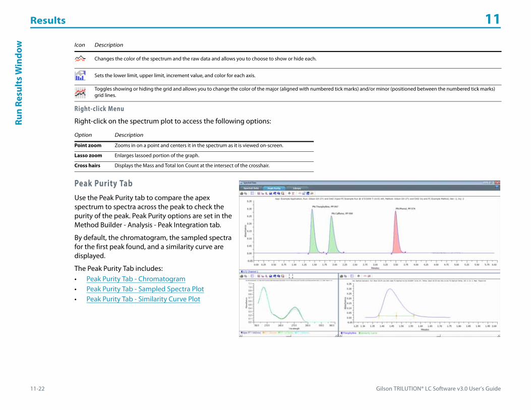
Results 11
11-22 Gilson TRILUTION® LC Software v3.0 User’s Guide
Run
Resu
lts
Win
dow
Right-click Menu
Right-click on the spectrum plot to access the following options:
Peak Purity TabUse the Peak Purity tab to compare the apex spectrum to spectra across the peak to check the purity of the peak. Peak Purity options are set in the Method Builder - Analysis - Peak Integration tab.
By default, the chromatogram, the sampled spectra for the first peak found, and a similarity curve are displayed.
The Peak Purity Tab includes:• Peak Purity Tab - Chromatogram• Peak Purity Tab - Sampled Spectra Plot• Peak Purity Tab - Similarity Curve Plot
Changes the color of the spectrum and the raw data and allows you to choose to show or hide each.
Sets the lower limit, upper limit, increment value, and color for each axis.
Toggles showing or hiding the grid and allows you to change the color of the major (aligned with numbered tick marks) and/or minor (positioned between the numbered tick marks) grid lines.
Option Description
Point zoom Zooms in on a point and centers it in the spectrum as it is viewed on-screen.
Lasso zoom Enlarges lassoed portion of the graph.
Cross hairs Displays the Mass and Total Ion Count at the intersect of the crosshair.
Icon Description
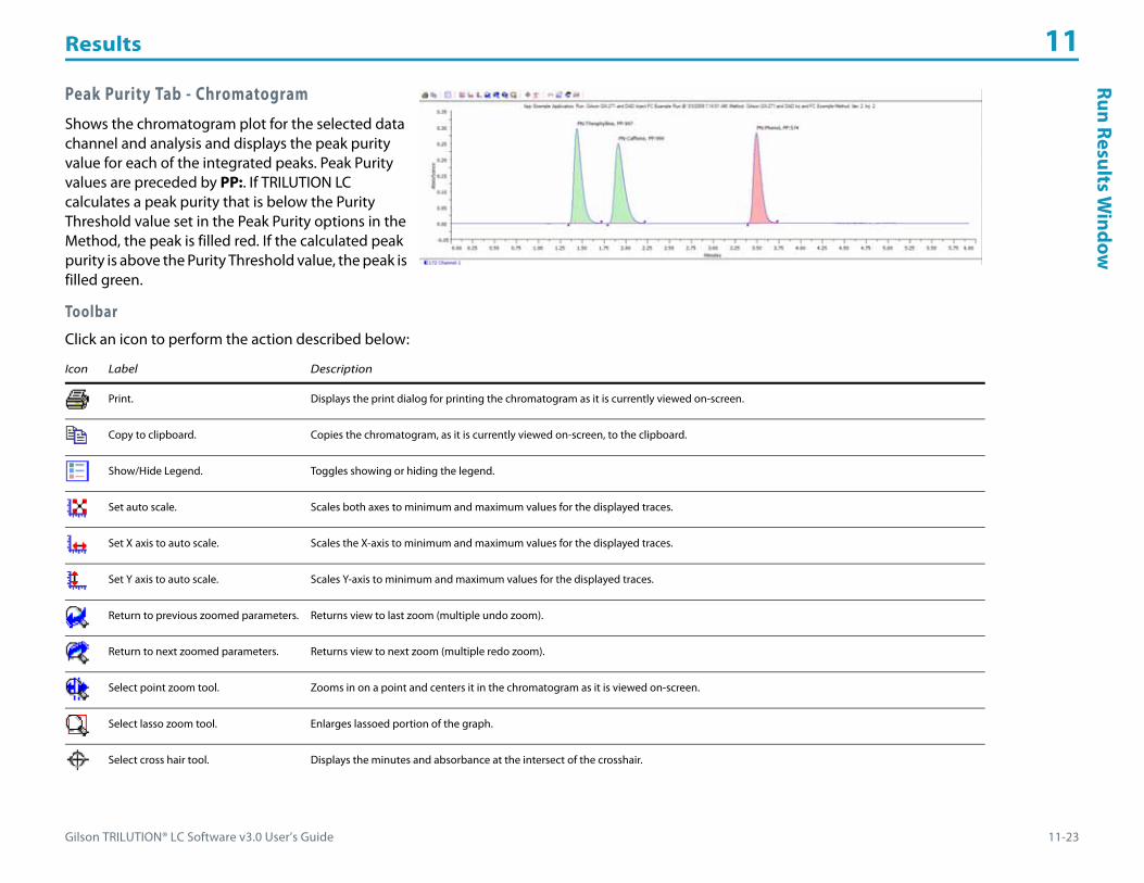
Gilson TRILUTION® LC Software v3.0 User’s Guide 11-23
Results 11Run Results W
indow
Peak Purity Tab - Chromatogram
Shows the chromatogram plot for the selected data channel and analysis and displays the peak purity value for each of the integrated peaks. Peak Purity values are preceded by PP:. If TRILUTION LC calculates a peak purity that is below the Purity Threshold value set in the Peak Purity options in the Method, the peak is filled red. If the calculated peak purity is above the Purity Threshold value, the peak is filled green.
Toolbar
Click an icon to perform the action described below:
Icon Label Description
Print. Displays the print dialog for printing the chromatogram as it is currently viewed on-screen.
Copy to clipboard. Copies the chromatogram, as it is currently viewed on-screen, to the clipboard.
Show/Hide Legend. Toggles showing or hiding the legend.
Set auto scale. Scales both axes to minimum and maximum values for the displayed traces.
Set X axis to auto scale. Scales the X-axis to minimum and maximum values for the displayed traces.
Set Y axis to auto scale. Scales Y-axis to minimum and maximum values for the displayed traces.
Return to previous zoomed parameters. Returns view to last zoom (multiple undo zoom).
Return to next zoomed parameters. Returns view to next zoom (multiple redo zoom).
Select point zoom tool. Zooms in on a point and centers it in the chromatogram as it is viewed on-screen.
Select lasso zoom tool. Enlarges lassoed portion of the graph.
Select cross hair tool. Displays the minutes and absorbance at the intersect of the crosshair.

Results 11
11-24 Gilson TRILUTION® LC Software v3.0 User’s Guide
Run
Resu
lts
Win
dow
Right-click Menu
Right-click on the chromatogram to access the following options:
Select the Move Channel tool ( ) and then right-click on a trace to display the following menu options:
Select move channel tool.Moves one or more of the traces.
This option can be used to offset a chromatogram that is overlapping another. It can also be helpful when subtracting or dividing chromatograms because you can adjust for varying retention times by aligning peaks in the chromatogram.
Channel Attributes. Changes the color of the trace allows you to choose to show or hide.
Axis Attributes. Sets the lower limit, upper limit, increment value, and color for each axis.
Peak Label Attributes. Changes the orientation and color of the peak name labels and allows you to choose to show or hide the labels.
Grid Attributes. Toggles showing or hiding the grid and allows you to change the color of the major (aligned with numbered tick marks) and/or minor (positioned between the numbered tick marks) grid lines.
Option Description
Point zoom Zooms in on a point and centers it in the chromatogram as it is viewed on-screen.
Lasso zoom Enlarges lassoed portion of the graph.
Cross hairs Displays the minutes and absorbance at the intersect of the crosshair.
Move channelMoves one or more of the traces.
This option can be used to offset a chromatogram that is overlapping another. It can also be helpful when subtracting or dividing chromatograms because you can adjust for varying retention times by aligning peaks in the chromatogram.
Menu Description
Set Offset Displays the Channel Offset Settings dialog which allows you to change the color of the displayed trace and offset the trace in either the X (Minutes) or Y (mVolts) direction.
Set mVolts Offsets After moving the trace, this option provides an additional menu to zero the trace (Zero), return the trace to the previous setting (Last Setting), or revert to the original setting (Original Setting) in the Y-direction.
Set All mVolts Offsets After moving multiple traces, this option provides an additional menu to zero the traces (Zero), return the traces to the previous setting (Last Setting), or revert to the original settings (Original Setting) in the Y-direction.
Set Minutes Offsets After moving the trace, this option provides an additional menu to zero the trace (Zero), return the trace to the previous setting (Last Setting), or revert to the original setting (Original Setting) in the X-direction.
Set All Minutes Offsets After moving multiple traces, this option provides an additional menu to zero the traces (Zero), return the traces to the previous setting (Last Setting), or revert to the original settings (Original Setting) in the X-direction.
Move in Minutes Only Allows you to move the trace only horizontally.
Move in mVolts Only Allows you to move the trace only vertically.
Icon Label Description
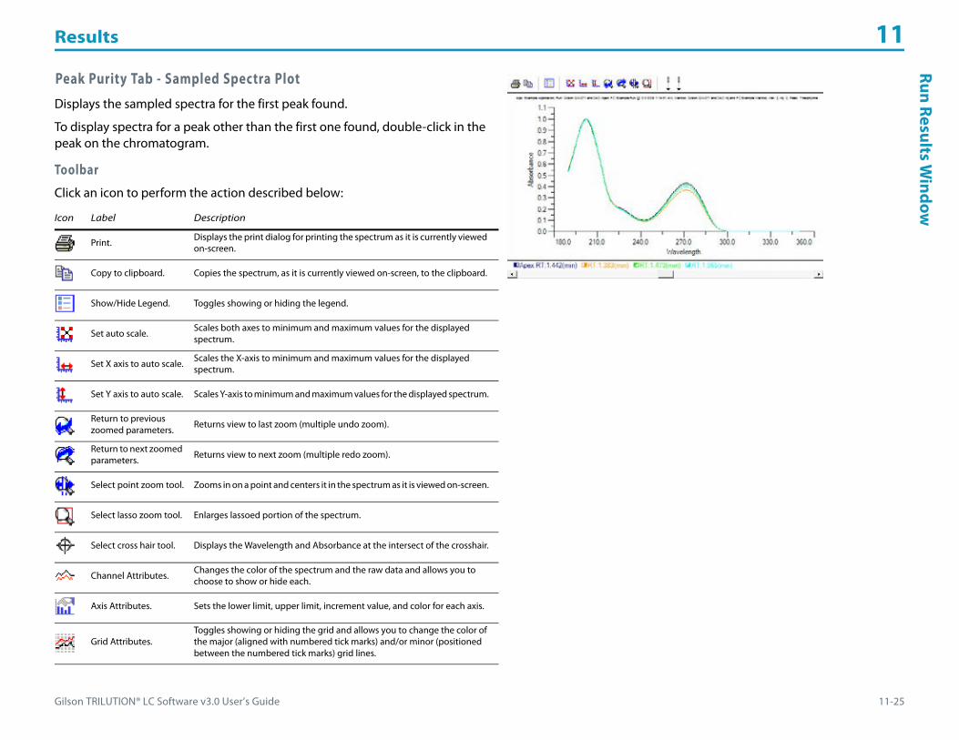
Gilson TRILUTION® LC Software v3.0 User’s Guide 11-25
Results 11Run Results W
indow
Peak Purity Tab - Sampled Spectra Plot
Displays the sampled spectra for the first peak found.
To display spectra for a peak other than the first one found, double-click in the peak on the chromatogram.
Toolbar
Click an icon to perform the action described below:
Icon Label Description
Print. Displays the print dialog for printing the spectrum as it is currently viewed on-screen.
Copy to clipboard. Copies the spectrum, as it is currently viewed on-screen, to the clipboard.
Show/Hide Legend. Toggles showing or hiding the legend.
Set auto scale. Scales both axes to minimum and maximum values for the displayed spectrum.
Set X axis to auto scale. Scales the X-axis to minimum and maximum values for the displayed spectrum.
Set Y axis to auto scale. Scales Y-axis to minimum and maximum values for the displayed spectrum.
Return to previous zoomed parameters. Returns view to last zoom (multiple undo zoom).
Return to next zoomed parameters. Returns view to next zoom (multiple redo zoom).
Select point zoom tool. Zooms in on a point and centers it in the spectrum as it is viewed on-screen.
Select lasso zoom tool. Enlarges lassoed portion of the spectrum.
Select cross hair tool. Displays the Wavelength and Absorbance at the intersect of the crosshair.
Channel Attributes. Changes the color of the spectrum and the raw data and allows you to choose to show or hide each.
Axis Attributes. Sets the lower limit, upper limit, increment value, and color for each axis.
Grid Attributes.Toggles showing or hiding the grid and allows you to change the color of the major (aligned with numbered tick marks) and/or minor (positioned between the numbered tick marks) grid lines.

Results 11
11-26 Gilson TRILUTION® LC Software v3.0 User’s Guide
Run
Resu
lts
Win
dow Right-click Menu
Right-click on the spectrum plot to access the following options:
Peak Purity Tab - Similarity Curve Plot
The similarity curve is a representation of individual purity calculations during elution. The number of points on the curve are the Number of Sampled Spectra selected in the Peak Purity options in the method.
Toolbar
Click an icon to perform the action described below:
Option Description
Point zoom Zooms in on a point and centers it in the spectrum as it is viewed on-screen.
Lasso zoom Enlarges lassoed portion of the graph.
Cross hairs Displays the Wavelength and Absorbance at the intersect of the crosshair.
Icon Label Description
Print. Displays the print dialog for printing the spectrum as it is currently viewed on-screen.
Copy to clipboard. Copies the spectrum, as it is currently viewed on-screen, to the clipboard.
Show/Hide Legend. Toggles showing or hiding the legend.
Select cross hair tool. Displays the Wavelength and Absorbance at the intersect of the crosshair.
Channel Attributes. Changes the color of the spectrum and the raw data and allows you to choose to show or hide each.
Grid Attributes. Toggles showing or hiding the grid and allows you to change the color of the major (aligned with numbered tick marks) and/or minor (positioned between the numbered tick marks) grid lines.

Gilson TRILUTION® LC Software v3.0 User’s Guide 11-27
Results 11Run Results W
indow
Right-click Menu
Right-click on the similarity curve plot to access the following options:
Library TabIn TRILUTION LC, you can assemble reference databases of spectra of known compounds. You can then search and match the database contents to the chromatogram for an unknown sample and report the outcome.
You can perform spectral matching at run time or during post-run re-analysis.
For information about diode array spectral libraries, refer to Library Tab (DAD).
For information about mass spectral libraries, refer to Library Tab (MS).
Library Tab (DAD)
In TRILUTION LC, you can assemble reference databases of spectra of known compounds. You can then search and match the database contents to the chromatogram for an unknown sample and report the outcome.
You can perform spectral matching at run time or during post-run re-analysis.
Option Description
Cross hairs Displays the Wavelength and Absorbance at the intersect of the crosshair.
Results 11
11-28 Gilson TRILUTION® LC Software v3.0 User’s Guide
Run
Resu
lts
Win
dow Action Buttons
The following action buttons are located on the Library tab.
Toolbar
Click an icon to perform the action described below:
Action Button Description
NewCreates a new library.
For more information, refer to Build a DAD Spectral Library.
Open Opens an existing library.
Delete Library Opens the Delete Spectral Library dialog for selecting libraries to delete.
Import Imports a .LCSL file.
Export Exports the Spectral Library to a specified location as a .LCSL file.
AddOpens the Add Spectral Library Entry dialog for adding a peak spectrum to one or more spectral libraries.
For more information, refer to Build a DAD Spectral Library.
ModifyOpens the Modify Spectral Library Entry dialog for modifying the comparison wavelength range or comment for an existing spectrum or for adding an existing spectrum to additional libraries.
For more information, refer to Modify a DAD Spectral Library Entry.
Delete Spectrum Opens the Select Spectral Library dialog for selecting libraries from which the open spectrum should be deleted.
SearchOpens the Search Spectral Library dialog for finding spectral matches for the selected peak.
For more information, refer to Search for DAD Spectral Matches.
Icon Label Description
Print. Displays the print dialog for printing the spectrum as it is currently viewed on-screen.
Copy to clipboard. Copies the spectrum, as it is currently viewed on-screen, to the clipboard.
Show/Hide Legend. Toggles showing or hiding the legend.
Set auto scale. Scales both axes to minimum and maximum values for the displayed spectrum.
Set X axis to auto scale. Scales the X-axis to minimum and maximum values for the displayed spectrum.
Set Y axis to auto scale. Scales Y-axis to minimum and maximum values for the displayed spectrum.
Return to previous zoomed parameters. Returns view to last zoom (multiple undo zoom).
Gilson TRILUTION® LC Software v3.0 User’s Guide 11-29
Results 11Run Results W
indow
Return to next zoomed parameters. Returns view to next zoom (multiple redo zoom).
Select point zoom tool. Zooms in on a point and centers it in the chromatogram as it is viewed on-screen.
Select lasso zoom tool. Enlarges lassoed portion of the spectrum.
Select cross hair tool. Displays the Wavelength and Absorbance at the intersect of the crosshair.
Channel Attributes. Changes the color of the spectrum and the raw data and allows you to choose to show or hide each.
Axis Attributes. Sets the lower limit, upper limit, increment value, and color for each axis.
Grid Attributes. Toggles showing or hiding the grid and allows you to change the color of the major (aligned with numbered tick marks) and/or minor (positioned between the numbered tick marks) grid lines.
Show Original/Normalized. Toggles showing peak spectrum and spectral match normalized and original.
Icon Label Description
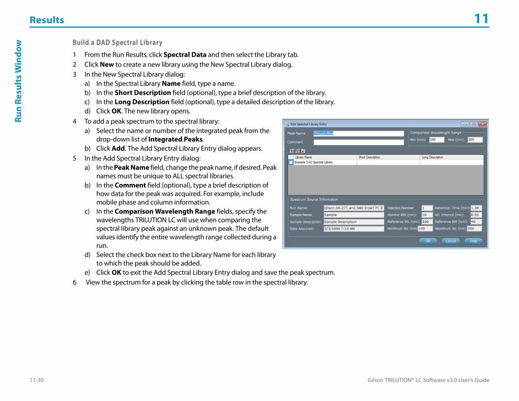
Results 11
11-30 Gilson TRILUTION® LC Software v3.0 User’s Guide
Run
Resu
lts
Win
dow Build a DAD Spectral Library
1 From the Run Results, click Spectral Data and then select the Library tab.2 Click New to create a new library using the New Spectral Library dialog.3 In the New Spectral Library dialog:
a) In the Spectral Library Name field, type a name.b) In the Short Description field (optional), type a brief description of the library.c) In the Long Description field (optional), type a detailed description of the library.d) Click OK. The new library opens.
4 To add a peak spectrum to the spectral library:a) Select the name or number of the integrated peak from the
drop-down list of Integrated Peaks.b) Click Add. The Add Spectral Library Entry dialog appears.
5 In the Add Spectral Library Entry dialog:a) In the Peak Name field, change the peak name, if desired. Peak
names must be unique to ALL spectral libraries.b) In the Comment field (optional), type a brief description of
how data for the peak was acquired. For example, include mobile phase and column information.
c) In the Comparison Wavelength Range fields, specify the wavelengths TRILUTION LC will use when comparing the spectral library peak against an unknown peak. The default values identify the entire wavelength range collected during a run.
d) Select the check box next to the Library Name for each library to which the peak should be added.
e) Click OK to exit the Add Spectral Library Entry dialog and save the peak spectrum.6 View the spectrum for a peak by clicking the table row in the spectral library.

Gilson TRILUTION® LC Software v3.0 User’s Guide 11-31
Results 11Run Results W
indow
Modify a DAD Spectral Library Entry1 Open a spectral library:
a) On the Library tab, click Open. The Open Spectral Library dialog appears.
b) Select the check box next to the Library Name for each library to open.
c) Click OK.2 Click to select a spectrum in the library. The spectrum opens
graphically below in a tabbed view.3 Click Modify to display the Modify Spectral Library Entry dialog.4 In the Modify Spectral Library dialog:
a) In the Comment field (optional), type a brief description of how data for the peak was acquired. For example, include mobile phase and column information.
b) In the Comparison Wavelength Range fields, specify the wavelengths TRILUTION LC will use when comparing the spectral library peak against an unknown peak. The default values identify the entire wavelength range collected during a run.
c) Select the check box next to the Library Name for each library to which the peak should be added.d) In the Minimum WL and Maximum WL fields, specify the wavelength range for the spectrum to be saved to the library.
5 Click OK.

Results 11
11-32 Gilson TRILUTION® LC Software v3.0 User’s Guide
Run
Resu
lts
Win
dow Search for DAD Spectral Matches
1 Select the name or number of one or more integrated peaks from the drop-down list of Integrated Peaks. As each peak is selected, a tab displays above the spectrum.
2 Click Search. The Search Spectral Library dialog appears.3 In the Search Spectral Library dialog:
a) Select the check box next to the Library Name for each library to be searched.
b) For each peak spectrum to match, do one of the following:• Select the check box next to the Peak Name and under All Peaks
to search all spectral library peaks.• Select the check box next to the Peak Name and under
Time Period and then enter Start and End times to limit the search to spectral library peaks whose retention times are within that time period.
c) In the Match Threshold field, indicate the smallest match value to be reported. A match value of 1000 indicates a perfect match.4 Click OK to begin the search.5 When the search completes, displays the five closest matches.6 In the tabbed spectrum view, select a spectrum. From the drop-down list of Library Matches, select a spectrum to overlay. The integrated peak
spectrum displays in red, the matched spectrum displays black.7 The peak spectrum and spectral match are normalized. To view the originals, click .8 To remove the overlaid spectrum, right-click on the spectrum tab and then select Close Tab to close the spectrum tab.
Delete DAD Spectral Library Entry1 Open a spectral library:
a) On the Library tab, click Open. The Open Spectral Library dialog appears.b) Select the check box next to the Library Name for each library to open.c) Click OK.
2 Click to select a spectrum in the library. The spectrum opens graphically below in a tabbed view.3 Click Delete Spectrum to display the Select Spectral Library dialog.4 In the Select Spectral Library dialog, select the libraries from which the open spectrum should be deleted.5 Click OK.

Gilson TRILUTION® LC Software v3.0 User’s Guide 11-33
Results 11Run Results W
indow
Export DAD Libraries1 To access the spectral libraries, do either of the following:
• From the Run Results, click Spectral Data and then select the Library tab.• From the Project Library, double-click DAD Spectral Libraries.
2 Click Export to display the Export window.3 In the Export window:
a) In the Select the items to be exported field, select the spectral libraries.b) Designate a path to which the libraries should be exported:
1) Click to display the Browse For folder window.2) On the Browse For folder window, select a folder, and then click OK.
4 Click OK. On completion of the export operation, the spectral libraries are saved in the specified folder with a .LCSL extension.
5 When the export success/fail dialog appears:• Click Details to view the log information of the export operation.• Click OK.
Import DAD Libraries1 To access the spectral libraries, do either of the following:
• From the Run Results, click Spectral Data and then select the Library tab.• From the Project Library, double-click DAD Spectral Libraries.
2 Click Import to display the Import window.3 From the Import window:
a) Browse for and select the Spectral Library Export Files (.LCSL).b) Click Open.
4 When the import success/fail dialog appears:• Click Details to view the log information of the import operation.• Click OK.

Results 11
11-34 Gilson TRILUTION® LC Software v3.0 User’s Guide
Run
Resu
lts
Win
dow Delete DAD Spectral Libraries
1 To access the spectral libraries, do either of the following:• From the Run Results, click Spectral Data and then select the Library tab.• From the Project Library, double-click DAD Spectral Libraries.
2 Click Delete Library to display the Delete Spectral Library dialog.3 Select the check box next to the name of each DAD spectral library to delete.4 Click OK.5 When asked to confirm the deletion, click OK. The DAD spectral libraries are deleted.
Library Tab (MS)
In TRILUTION LC, you can assemble reference databases of spectra of known compounds. You can then search and match the database contents to the chromatogram for an unknown sample and report the outcome.
You can perform spectral matching at run time or during post-run re-analysis.

Gilson TRILUTION® LC Software v3.0 User’s Guide 11-35
Results 11Run Results W
indow
Action Buttons
The following action buttons are located on the Library tab.
Action Button Description
NewCreates a new library.
For more information, refer to Build a Mass Spectral Library.
Open Opens an existing library.
Delete Library Opens the Delete Mass Spectral Library dialog for selecting libraries to delete.
Import Imports a .LCML file.
Export Exports the Spectral Library to a specified location as a .LCML file.
AddOpens the Add Mass Spectral Library Entry dialog for adding a peak spectrum to one or more spectral libraries.
For more information, refer to Build a Mass Spectral Library.
ModifyOpens the Modify Mass Spectral Library Entry dialog for modifying the MS Comparison Parameters (m/z) or comment for an existing spectrum or for adding an existing spectrum to additional libraries.
For more information, refer to Modify a Mass Spectral Library Entry.
Delete Spectrum Opens the Select Spectral Library dialog for selecting libraries from which the open spectrum should be deleted.
SearchOpens the Search Mass Spectral Library dialog for finding spectral matches for the selected peak.
For more information, refer to Search for Mass Spectral Matches.

Results 11
11-36 Gilson TRILUTION® LC Software v3.0 User’s Guide
Run
Resu
lts
Win
dow Toolbar
Click an icon to perform the action described below:
Icon Description
Displays the print dialog for printing the spectrum as it is currently viewed on-screen.
Copies the spectrum, as it is currently viewed on-screen, to the clipboard.
Toggles showing or hiding the legend.
Scales both axes to minimum and maximum values for the displayed spectrum.
Scales the X-axis to minimum and maximum values for the displayed spectrum.
Scales Y-axis to minimum and maximum values for the displayed spectrum.
Returns view to last zoom (multiple undo zoom).
Returns view to next zoom (multiple redo zoom).
Zooms in on a point and centers it in the chromatogram as it is viewed on-screen.
Enlarges lassoed portion of the spectrum.
Displays the ion count and mass (m/z) at the intersect of the crosshair.
Changes the color of the spectrum and the raw data and allows you to choose to show or hide each.
Sets the lower limit, upper limit, increment value, and color for each axis.
Toggles showing or hiding the grid and allows you to change the color of the major (aligned with numbered tick marks) and/or minor (positioned between the numbered tick marks) grid lines.
Toggles showing peak spectrum and spectral match normalized and original.
Toggle button for hiding or showing the background.

Gilson TRILUTION® LC Software v3.0 User’s Guide 11-37
Results 11Run Results W
indow
Build a Mass Spectral Library1 From the Run Results, click Spectral Data and then select the Library tab.2 Click New to create a new library using the New Spectral Library dialog.3 In the New Spectral Library dialog:
a) In the Library Name field, type a name.b) In the Short Description field (optional), type a brief description of the library.c) In the Long Description field (optional), type a detailed description of the library.d) Click OK. The new library opens.
4 To add a peak spectrum into the spectral library:a) Select the name or number of the integrated peak from the
drop-down list of Integrated Peaks.b) Click Add. The Add Mass Spectral Library Entry dialog appears.
5 In the Add Spectral Library Entry dialog:a) In the Peak Name field, change the peak name, if desired. Peak
names must be unique to ALL spectral libraries.b) In the Comment field (optional), type a brief description of
how data for the peak was acquired. For example, include mobile phase and column information.
c) In the MS Comparison Parameters (m/z) fields, specify the masses TRILUTION LC will use when comparing the spectral library peak against an unknown peak. The default values identify the entire scan range collected during a run.
d) Select the check box next to the Library Name for each library to which the peak should be added.
e) Click OK to exit the Add Mass Spectral Library Entry dialog and save the peak spectrum.6 View the spectrum for a peak by clicking the table row in the spectral library.
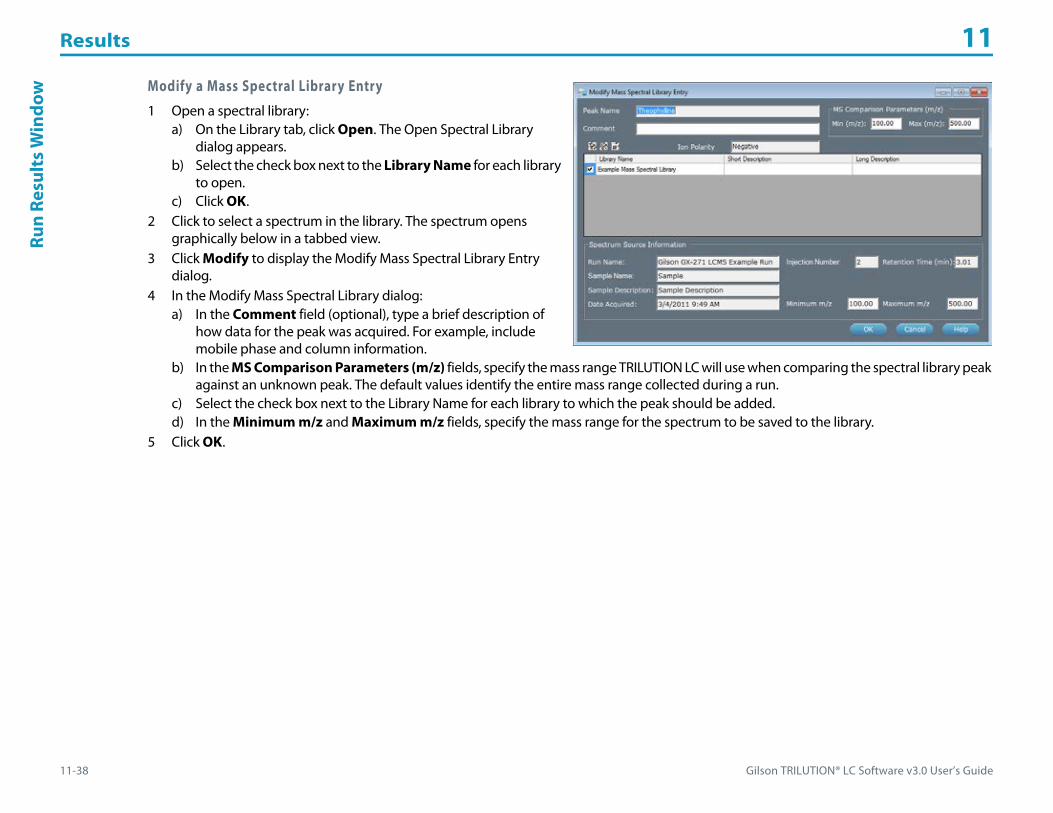
Results 11
11-38 Gilson TRILUTION® LC Software v3.0 User’s Guide
Run
Resu
lts
Win
dow Modify a Mass Spectral Library Entry
1 Open a spectral library:a) On the Library tab, click Open. The Open Spectral Library
dialog appears.b) Select the check box next to the Library Name for each library
to open.c) Click OK.
2 Click to select a spectrum in the library. The spectrum opens graphically below in a tabbed view.
3 Click Modify to display the Modify Mass Spectral Library Entry dialog.
4 In the Modify Mass Spectral Library dialog:a) In the Comment field (optional), type a brief description of
how data for the peak was acquired. For example, include mobile phase and column information.
b) In the MS Comparison Parameters (m/z) fields, specify the mass range TRILUTION LC will use when comparing the spectral library peak against an unknown peak. The default values identify the entire mass range collected during a run.
c) Select the check box next to the Library Name for each library to which the peak should be added.d) In the Minimum m/z and Maximum m/z fields, specify the mass range for the spectrum to be saved to the library.
5 Click OK.
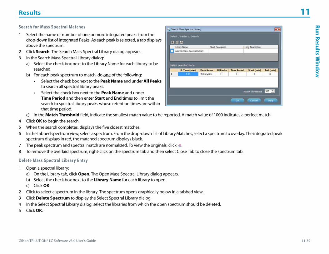
Gilson TRILUTION® LC Software v3.0 User’s Guide 11-39
Results 11Run Results W
indow
Search for Mass Spectral Matches1 Select the name or number of one or more integrated peaks from the
drop-down list of Integrated Peaks. As each peak is selected, a tab displays above the spectrum.
2 Click Search. The Search Mass Spectral Library dialog appears.3 In the Search Mass Spectral Library dialog:
a) Select the check box next to the Library Name for each library to be searched.
b) For each peak spectrum to match, do one of the following:• Select the check box next to the Peak Name and under All Peaks
to search all spectral library peaks.• Select the check box next to the Peak Name and under
Time Period and then enter Start and End times to limit the search to spectral library peaks whose retention times are within that time period.
c) In the Match Threshold field, indicate the smallest match value to be reported. A match value of 1000 indicates a perfect match.4 Click OK to begin the search.5 When the search completes, displays the five closest matches.6 In the tabbed spectrum view, select a spectrum. From the drop-down list of Library Matches, select a spectrum to overlay. The integrated peak
spectrum displays in red, the matched spectrum displays black.7 The peak spectrum and spectral match are normalized. To view the originals, click .8 To remove the overlaid spectrum, right-click on the spectrum tab and then select Close Tab to close the spectrum tab.
Delete Mass Spectral Library Entry1 Open a spectral library:
a) On the Library tab, click Open. The Open Mass Spectral Library dialog appears.b) Select the check box next to the Library Name for each library to open.c) Click OK.
2 Click to select a spectrum in the library. The spectrum opens graphically below in a tabbed view.3 Click Delete Spectrum to display the Select Spectral Library dialog.4 In the Select Spectral Library dialog, select the libraries from which the open spectrum should be deleted.5 Click OK.

Results 11
11-40 Gilson TRILUTION® LC Software v3.0 User’s Guide
Run
Resu
lts
Win
dow Export Mass Spectral Libraries
1 To access the spectral libraries, do either of the following:• From the Run Results, click Spectral Data and then select the Library tab.• From the Project Library, double-click Mass Spectral Libraries.
2 Click Export to display the Export window.3 In the Export window:
a) In the Select the items to be exported field, select the spectral libraries.b) Designate a path to which the libraries should be exported:
1) Click to display the Browse For folder window.2) On the Browse For folder window, select a folder, and then click OK.
4 Click OK. On completion of the export operation, the spectral libraries are saved in the specified folder with a .LCML extension.
5 When the export success/fail dialog appears:• Click Details to view the log information of the export operation.• Click OK.
Import Mass Spectral Libraries1 To access the spectral libraries, do either of the following:
• From the Run Results, click Spectral Data and then select the Library tab.• From the Project Library, double-click Mass Spectral Libraries.
2 Click Import to display the Import window.3 From the Import window:
a) Browse for and select the Spectral Library Export Files (.LCML).b) Click Open.
4 When the import success/fail dialog appears:• Click Details to view the log information of the import operation.• Click OK.

Gilson TRILUTION® LC Software v3.0 User’s Guide 11-41
Results 11Run Results W
indow
Delete Mass Spectral Libraries1 To access the spectral libraries, do one of the following:
• From the Run Results, click Spectral Data and then select the Library tab.• From the Project Library, double-click Mass Spectral Libraries.
2 Click Delete Library to display the Delete Spectral Library dialog.3 Select the check box next to the name of each mass spectral library to delete.4 Click OK.5 When asked to confirm the deletion, click OK. The mass spectral libraries are deleted.
ChromatogramShows the chromatogram plot for collected traces in mV, Absorbance, TIC, or user units.
The following example shows one channel using mV and the other channel using user units as set in the configuration for the detector. The color and pattern of the symbol on the axis corresponds to the symbol and color used to identify the data channel in the legend.
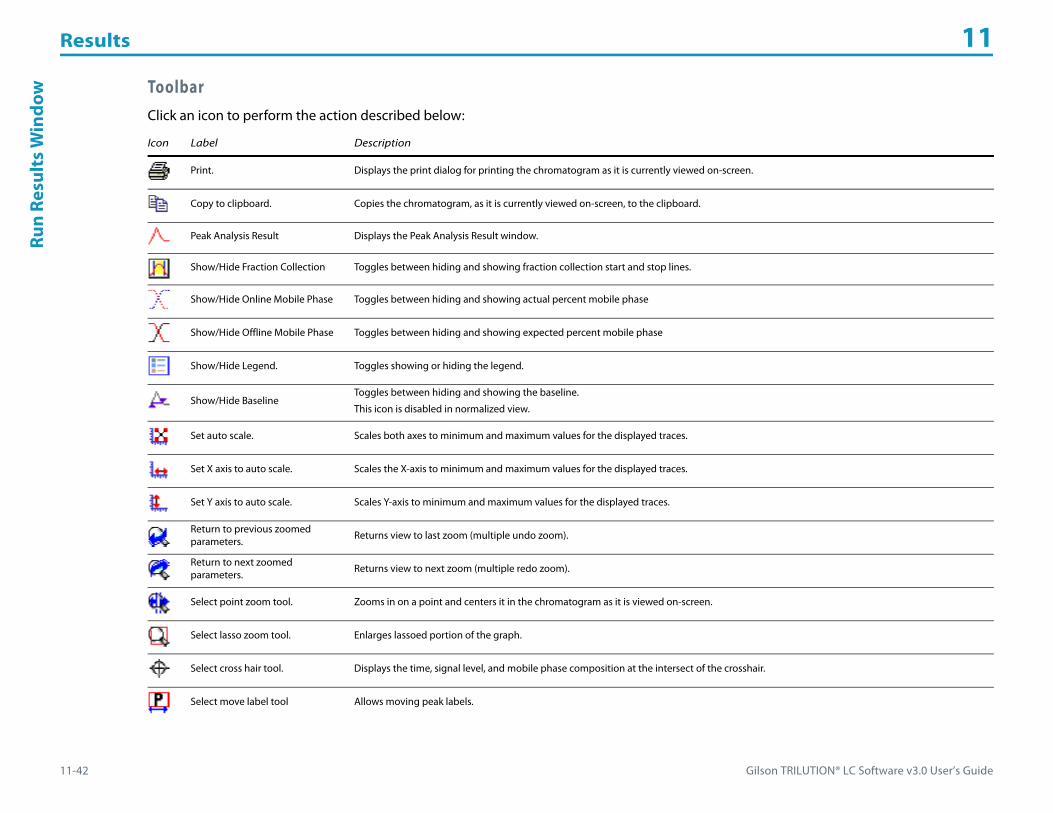
Results 11
11-42 Gilson TRILUTION® LC Software v3.0 User’s Guide
Run
Resu
lts
Win
dow Toolbar
Click an icon to perform the action described below:
Icon Label Description
Print. Displays the print dialog for printing the chromatogram as it is currently viewed on-screen.
Copy to clipboard. Copies the chromatogram, as it is currently viewed on-screen, to the clipboard.
Peak Analysis Result Displays the Peak Analysis Result window.
Show/Hide Fraction Collection Toggles between hiding and showing fraction collection start and stop lines.
Show/Hide Online Mobile Phase Toggles between hiding and showing actual percent mobile phase
Show/Hide Offline Mobile Phase Toggles between hiding and showing expected percent mobile phase
Show/Hide Legend. Toggles showing or hiding the legend.
Show/Hide BaselineToggles between hiding and showing the baseline.
This icon is disabled in normalized view.
Set auto scale. Scales both axes to minimum and maximum values for the displayed traces.
Set X axis to auto scale. Scales the X-axis to minimum and maximum values for the displayed traces.
Set Y axis to auto scale. Scales Y-axis to minimum and maximum values for the displayed traces.
Return to previous zoomed parameters. Returns view to last zoom (multiple undo zoom).
Return to next zoomed parameters. Returns view to next zoom (multiple redo zoom).
Select point zoom tool. Zooms in on a point and centers it in the chromatogram as it is viewed on-screen.
Select lasso zoom tool. Enlarges lassoed portion of the graph.
Select cross hair tool. Displays the time, signal level, and mobile phase composition at the intersect of the crosshair.
Select move label tool Allows moving peak labels.

Gilson TRILUTION® LC Software v3.0 User’s Guide 11-43
Results 11Run Results W
indow
Select color peak region toolAllows coloring peaks. Named peaks use the color assigned in the peak table. Unnamed peaks use green.
This icon is disabled in normalized view.
Select move channel toolMoves one or more of the traces.
This option can be used to offset a chromatogram that is overlapping another. It can also be helpful when subtracting or dividing chromatograms since you can adjust for varying retention times by aligning peaks in the chromatogram.
Select move baseline tool
Allows selecting a peak for which the baseline will be modified or deleted.
This icon is disabled in normalized view.
For more information, refer to Manual Baseline Adjustment.
Select delete baseline tool
After using the move baseline tool ( ) to select the baseline, click to delete the selected baseline.
This icon is disabled in normalized view.
For more information, refer to Manual Baseline Adjustment.
Select snap baseline tool
After using the move baseline tool ( ) to select the baseline, click to snap all points to the baseline.
This icon is disabled in normalized view.
For more information, refer to Manual Baseline Adjustment.
Select snap baseline endpoint tool
After using the move baseline tool ( ) to select the baseline, click to snap endpoints to the baseline.
This icon is disabled in normalized view.
For more information, refer to Manual Baseline Adjustment.
Select insert baseline tool
Inserts a new baseline.
This icon is disabled in normalized view.
For more information, refer to Manual Baseline Adjustment.
Channel Attributes. Changes the color of the traces and mobile phase and allows you to choose to show or hide each.
Axis Attributes. Sets the lower limit, upper limit, increment value, and color for each axis.
Peak Label Attributes. Changes the orientation and color of the peak name labels and allows you to choose to show or hide the label.
Grid Attributes. Toggles showing or hiding the grid and allows you to change the color of the major (aligned with numbered tick marks) and/or minor (positioned between the numbered tick marks) grid lines.
Show Original/NormalizedToggles showing the original and the normalized view.
The normalized view scales all data to fit within a 0–1.0 Y-axis range.
Icon Label Description

Results 11
11-44 Gilson TRILUTION® LC Software v3.0 User’s Guide
Run
Resu
lts
Win
dow Right-click Menu
Right-click in the graph to display the following menu options:
Select the Move Channel tool ( ) and then right-click on a trace to display the following menu options:
Menu Description
Point zoom Zooms in on a point and centers it in the chromatogram as it is viewed on-screen.
Lasso zoom Enlarges lassoed portion of the graph.
Cross hairs Displays the minutes and mVolts at the intersect of the crosshair.
Move channelMoves one or more of the traces.
This option can be used to offset a chromatogram that is overlapping another. It can also be helpful when subtracting or dividing chromatograms since you can adjust for varying retention times by aligning peaks in the chromatogram.
Move label Allows moving peak labels.
Move baseline Allows selecting a peak for which the baseline will be modified or deleted.
Delete baseline Deletes the selected baseline.
Snap baseline Snaps all points to the baseline.
Snap baseline endpoint
Allows snapping points to the baseline.
Color peak region Allows coloring peaks. Named peaks use the color assigned in the peak table. Unnamed peaks use green.
Insert baseline Inserts a new baseline.
Menu Description
Set Offset Displays the Channel Offset Settings dialog which allows you to change the color of the displayed trace and offset the trace in either the X (Minutes) or Y (mVolts) direction.
Set mVolts Offsets After moving the trace, this option provides an additional menu to zero the trace (Zero), return the trace to the previous setting (Last Setting), or revert to the original setting (Original Setting) in the Y-direction.
Set All mVolts Offsets After moving multiple traces, this option provides an additional menu to zero the traces (Zero), return the traces to the previous setting (Last Setting), or revert to the original settings (Original Setting) in the Y-direction.
Set Minutes Offsets After moving the trace, this option provides an additional menu to zero the trace (Zero), return the trace to the previous setting (Last Setting), or revert to the original setting (Original Setting) in the X-direction.
Set All Minutes Offsets After moving multiple traces, this option provides an additional menu to zero the traces (Zero), return the traces to the previous setting (Last Setting), or revert to the original settings (Original Setting) in the X-direction.
Move in Minutes Only Allows moving the trace only horizontally.
Move in mVolts Only Allows moving the trace only vertically.

Gilson TRILUTION® LC Software v3.0 User’s Guide 11-45
Results 11Run Results W
indow
Sample Bed LayoutShows the location on the bed layout for the selected sample.
Fraction Bed LayoutShows the location on the bed layout of the fractions collected from the selected sample.
Double-click on the fraction to display the background subtracted mass spec fraction spectra, if applicable.
Mass Spec Spectra for FractionsDouble-click on a fraction in the Fraction Bed Layout to display the background subtracted mass spec fraction spectra, if applicable.

Results 11
11-46 Gilson TRILUTION® LC Software v3.0 User’s Guide
Run
Resu
lts
Win
dow Action Buttons
The following action buttons are located in the lower left corner of the Run Results window.
Info WindowDisplays Application name, Run Name, Method name and version, Sample Name and Sample Number, and whether or not the results were from a manual run.
Action Button Description
Save Saves changes made to the Run Results after re-analysis or analysis of manual changes.
Preview View the analysis for all samples for a single Method, Device/Channel, and Analysis. The method is selected from the Samples drop-down list. For more information about the analysis report and additional ways to view it, refer to Chapter 14, Reports.
Re-AnalyzeAnalyzes data using new conditions and/or integrates peaks differently.
For more information, refer to How to Analyze Data in a Different Way.
Analyze Manual Changes Analyzes data after a Manual Baseline Adjustment.
Edit Opens the Peak Integration and Report tabs for modification.
Previous Selects the previous sample.
Next Selects the next sample.
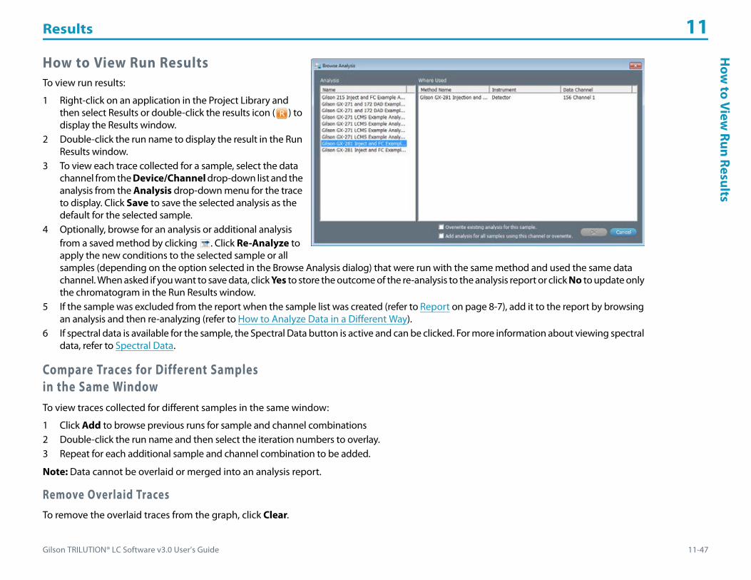
Gilson TRILUTION® LC Software v3.0 User’s Guide 11-47
Results 11H
ow to View
Run Results
How to View Run ResultsTo view run results:
1 Right-click on an application in the Project Library and then select Results or double-click the results icon ( ) to display the Results window.
2 Double-click the run name to display the result in the Run Results window.
3 To view each trace collected for a sample, select the data channel from the Device/Channel drop-down list and the analysis from the Analysis drop-down menu for the trace to display. Click Save to save the selected analysis as the default for the selected sample.
4 Optionally, browse for an analysis or additional analysis from a saved method by clicking . Click Re-Analyze to apply the new conditions to the selected sample or all samples (depending on the option selected in the Browse Analysis dialog) that were run with the same method and used the same data channel. When asked if you want to save data, click Yes to store the outcome of the re-analysis to the analysis report or click No to update only the chromatogram in the Run Results window.
5 If the sample was excluded from the report when the sample list was created (refer to Report on page 8-7), add it to the report by browsing an analysis and then re-analyzing (refer to How to Analyze Data in a Different Way).
6 If spectral data is available for the sample, the Spectral Data button is active and can be clicked. For more information about viewing spectral data, refer to Spectral Data.
Compare Traces for Different Samplesin the Same WindowTo view traces collected for different samples in the same window:
1 Click Add to browse previous runs for sample and channel combinations2 Double-click the run name and then select the iteration numbers to overlay.3 Repeat for each additional sample and channel combination to be added.
Note: Data cannot be overlaid or merged into an analysis report.
Remove Overlaid TracesTo remove the overlaid traces from the graph, click Clear.

Results 11
11-48 Gilson TRILUTION® LC Software v3.0 User’s Guide
How
to V
iew
Run
Res
ults How to Overlay Results to Compare Sample Traces
View traces collected for different samples in the same window:
1 Click Add to browse previous runs for sample and channel combinations.2 Double-click the run name and then select the iteration numbers to overlay.3 Repeat for each additional sample and channel combination to be added.
Note: Data cannot be overlaid or merged into an Analysis Report.
Remove Overlaid TracesTo remove the overlaid traces from the graph, click Clear.

Gilson TRILUTION® LC Software v3.0 User’s Guide 11-49
Results 11H
ow to A
nalyze Data in a D
ifferent Way
How to Analyze Data in a Different WayThe Run Results window enables modifying the analysis (for the open results only) in the Result Analysis Builder so the data can be analyzed using new conditions and peaks can be integrated differently. Optionally, the outcome of the analysis can be stored to the analysis report.
1 Click Edit.2 Modify analysis parameters by doing any or all of the following:
• change the Peak Table.• change integration events. Refer to Peak Integration Tab on page 7-2.• change channel scaling parameters. Refer to Data Channel Settings on page 7-24.• change report settings. Refer to Report Tab on page 7-14.
3 Click OK to return to the Run Results window.4 In the Run Results window, click Re-Analyze. When asked if you want to save data, click Yes to store the outcome of the re-analysis to the
analysis report. Click No to update the chromatogram in the Run Results window.5 If re-analyzing a calibration, the Recalibration Amount window appears. Do any of the following:
• Add or remove samples from the calibration curve by selecting or clearing the check box next to the sample number.• Modify the actual and nominal amounts for each peak.• Click OK to accept any changes made and re-analyze or click Cancel to reject the changes made and re-analyze.
6 Optionally, manually adjust baselines (refer to Manual Baseline Adjustment).

Results 11
11-50 Gilson TRILUTION® LC Software v3.0 User’s Guide
Man
ual B
asel
ine
Adj
ustm
ent Manual Baseline Adjustment
View and modify the baseline generated for samples. Changes to the baseline affect peak integration reporting in all reports.
Adjust the baseline for a peak, integrate a peak, or disable integration of a peak.
Adjust the baseline for a peak. To adjust the baseline beneath a peak, use the Move Baseline tool ( ) to select the peak, and then point and drag the points at the beginning or end of the peak.
Integrate a peak. To integrate a peak not currently integrated, use the Insert Baseline tool ( ). Move the mouse pointer to the starting point for the peak. Click and drag the mouse pointer below a peak to draw its baseline. Release the mouse button to set the end point for the peak.
Remove peak integration. To inhibit integration of a peak, use the Move Baseline tool ( ) to select the peak, and then click the Delete
Baseline icon ( ).
To adjust the baseline:
1 Select either the begin point (up triangle) and end point (down triangle) for each integrated peak.2 Drag to the desired location then release.
a) To snap all points back to the baseline, click the Snap Baseline icon ( ).
b) To snap points back to the baseline, select the Snap Baseline Endpoint tool ( ) and then click each point to snap to the baseline.3 Click Analyze Manual Changes.
a) Click Yes to save data.b) Click No to save data later. To save data later, click Save.
Re-analyzing after a manual baseline adjustment cancels any baseline changes.
Gilson TRILUTION® LC Software v3.0 User’s Guide 12-1
Calibrations 12
Generate calibration plots during an HPLC run or a batch re-analysis of calibrator samples. Access calibrations from the Results window by selecting the Calibrations tab. For more information about the Results window, refer to Results Window on page 11-2.
Key concepts to understand about calibrations are:
• How to View Calibrations
• How to Recalibrate and Re-analyze

Calibrations 12
12-2 Gilson TRILUTION® LC Software v3.0 User’s Guide
Resu
lts
Win
dow
- Ca
libra
tion
Tab Results Window - Calibration Tab
Double-click the run name (channel) to show the calibration plot that is used to calculate amounts for unknown samples. Examine the calibration curve generated for each standard peak. Viewing calibration plots is especially important if quadratic or cubic was the curve fitting method used to generate them.
For more information about setting up a run as a calibration, refer to Calibration on page 7-7.

Gilson TRILUTION® LC Software v3.0 User’s Guide 12-3
Calibrations 12Calibration
Window
Calibration Window
Graph PaneThe graph pane shows the calibration plot.
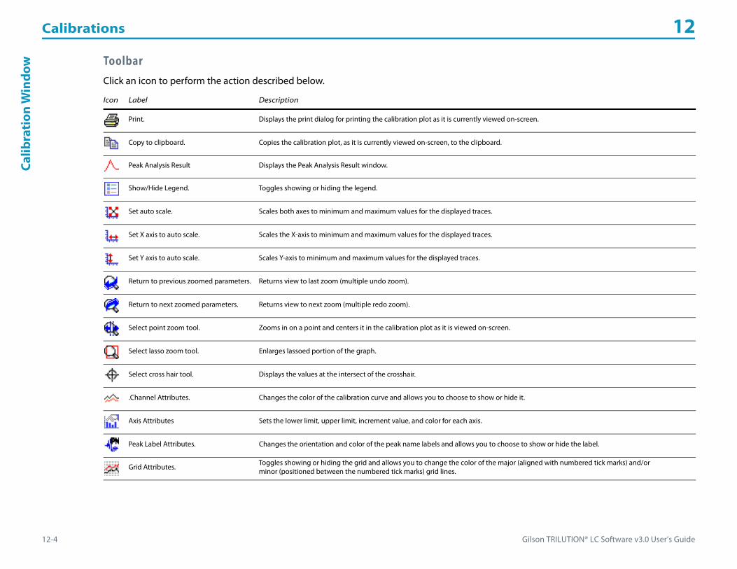
Calibrations 12
12-4 Gilson TRILUTION® LC Software v3.0 User’s Guide
Calib
rati
onW
indo
w ToolbarClick an icon to perform the action described below.
Icon Label Description
Print. Displays the print dialog for printing the calibration plot as it is currently viewed on-screen.
Copy to clipboard. Copies the calibration plot, as it is currently viewed on-screen, to the clipboard.
Peak Analysis Result Displays the Peak Analysis Result window.
Show/Hide Legend. Toggles showing or hiding the legend.
Set auto scale. Scales both axes to minimum and maximum values for the displayed traces.
Set X axis to auto scale. Scales the X-axis to minimum and maximum values for the displayed traces.
Set Y axis to auto scale. Scales Y-axis to minimum and maximum values for the displayed traces.
Return to previous zoomed parameters. Returns view to last zoom (multiple undo zoom).
Return to next zoomed parameters. Returns view to next zoom (multiple redo zoom).
Select point zoom tool. Zooms in on a point and centers it in the calibration plot as it is viewed on-screen.
Select lasso zoom tool. Enlarges lassoed portion of the graph.
Select cross hair tool. Displays the values at the intersect of the crosshair.
.Channel Attributes. Changes the color of the calibration curve and allows you to choose to show or hide it.
Axis Attributes Sets the lower limit, upper limit, increment value, and color for each axis.
Peak Label Attributes. Changes the orientation and color of the peak name labels and allows you to choose to show or hide the label.
Grid Attributes. Toggles showing or hiding the grid and allows you to change the color of the major (aligned with numbered tick marks) and/or minor (positioned between the numbered tick marks) grid lines.

Gilson TRILUTION® LC Software v3.0 User’s Guide 12-5
Calibrations 12H
ow to View
Calibrations
How to View Calibrations
View Calibration CurveTo view the calibration curve, select an analysis from the drop-down and a named peak from the list.
Calibration ReportThis report comprises seven parts: Annotation (includes optionally a heading, listing of the analysis tasks, listing of the control tasks, details about the data channel settings, the peak table, a listing of the control error conditions, and a listing of the analysis error conditions), Graph (chromatogram), Sample Table (user-specified column contents, may include custom calculations), and Run Variables (a listing of values for all variables used in the application run), Calibration Plot (the calibration curve data generated by the standards), and Calibration Plot Table (user-specified column contents for standards and controls, may include custom calculations).
View the Calibration ReportTo view results from a chromatographic run in which calibrators were injected, click Preview to view the Calibration Report.
The Calibration Report appears, displaying the report information selected on the Method Builder|Analysis|Report tab from the selected analysis for the selected peak.
Calibrations 12
12-6 Gilson TRILUTION® LC Software v3.0 User’s Guide
How
to R
ecal
ibra
te a
nd R
e-an
alyz
e How to Recalibrate and Re-analyzeThe Recalibration window allows you to add or remove samples from the calibration curve. You can also modify the actual and nominal amounts for each peak. The outcome of the recalibration is stored to a Calibration Report.
To modify the calibration:
1 Access the Run Results window by double-clicking the run name (channel) in the Results tab of the Results window.2 Click Re-Analyze.3 The Recalibration Amount window appears. Do any of the following:
• Add or remove samples from the calibration curve by selecting or clearing the check box next to the sample number. • Modify the Actual Amount and/or Nominal Amount for each peak. If there is a red border around the row number, it is an internal
standard.4 Click OK to accept any changes made and re-analyze or click Cancel to reject the changes made and re-analyze.
Export/Archive/Restore CalibrationsFor information on exporting calibrations, refer to How to Export Results on page 11-7.
For information on archiving calibrations, refer to How to Archive Results on page 11-7.
For information on restoring calibrations, refer to How to Restore Results on page 11-8.

Gilson TRILUTION® LC Software v3.0 User’s Guide 13-1
Working with Variables 13
To make tasks and methods more flexible, use a variable for a command or task property. When creating a method, assign values to any undefined variables used by any tasks. When setting a sample list for a run, assign values to any undefined variables used by the method. A message will be displayed when adding a task to a method or when beginning an application run if a value has not been assigned to a variable or if a variable has an invalid entry.
Two types of variables are available for creation and use in TRILUTION LC: Local (value type) variables and Global (reference type) variables.
Local variables are only visible in the Variable List in the task or method in which they were created. The values for local variables are specific to each task or each method iteration and are reset before running the next task or method iteration.
Global variables are available in all tasks and methods and do not reset for each task or each method iteration, thus enabling values to be passed from task to task or iteration to iteration.
Global variables are useful for:
• maintaining changes to variables throughout the application
• applying conditional logic to device feedback at runtime (especially when using GEARS)
This chapter includes:
• How to Create a New Variable
• View or Filter Variables
• Modify Local Variable Properties
• Delete a Local Variable

Working with Variables 13
13-2 Gilson TRILUTION® LC Software v3.0 User’s Guide
How
to C
reat
e a
New
Var
iabl
e How to Create a New VariableVariables can be created for task properties in the Method Builder; refer to Create a New Variable (Method Builder).
Variables can be created for command and/or task properties in the Task Builder; refer to Create a New Variable (Task Builder).
Create a New Variable (Method Builder)To create a variable:
1 On the Method Builder - Control tab, click , which opens the advanced Variable Properties dialog.
2 When the advanced Variable Properties dialog appears:a) In the Name field, enter a unique name for the variable.b) In the Type field, select a variable type from the drop-down menu. c) Optionally, enter a default value for the variable (if applicable).d) Optionally, enter the minimum value and maximum value (range) for
the variable (if applicable).e) Select the option for the variable type: Local (value type) or Global (reference type). (Local is selected by default.)f ) Select Show in parent to display the variable in the sample list, even if the variable is not being used. It is selected by default for local
variables. For global variables, it is not selected by default.
3 Click Add. Repeat steps 2 and 3 to create additional variables.4 When finished creating variables, click OK.
Another way to create a local variable is by entering a unique variable name, instead of a value, for a task property in the Method Builder. A local variable name begins with #, and can be any combination of letters and numbers and can contain some special characters. Valid local variable names would be #FlowRate and #Sample_Vol1.
To make an existing global variable available for use in the method, select Visible in Method for the variable in the Global Variable list.To make all global variables available for use in the method, click Select All.To clear the Visible in Method selection for all global variables, click Deselect All.

Gilson TRILUTION® LC Software v3.0 User’s Guide 13-3
Working with Variables 13H
ow to Create a N
ew Variable
Create a New Variable (Task Builder)To create a variable:
1 In the Task Builder window, do either of the following:
• Click , which opens the Variable Properties dialog.• Drag the Variable operator ( ), and then drop it in the workspace, which opens the basic
Variable Properties dialog.2 When the Variable Properties dialog appears:
a) In the Name field, enter a unique name for the variable.b) In the Type field, select a variable type from the drop-down menu.c) Optionally, enter a default value for the variable (if applicable).d) Optionally, enter the minimum value and maximum value (range) for the variable (if applicable).e) Select the option for the variable type: Local (value type) or Global (reference type). (Local is selected
by default.)f ) Select Show in parent to display the variable in the Method Builder, even if the variable is not being
used. It is selected by default for local variables. For global variables, it is not selected by default.g) Optionally, click the arrow to display the advanced options, and then add values to the Value List by
typing the value. Values entered in this list display as drop-down values in the task or command in which the variable is used.
3 Click Add. Repeat steps 2 and 3 to create additional variables.4 When finished creating variables, click OK.
Another way to create a local variable is by entering a unique variable name, instead of a value, for a task or command property in the Task Builder. A local variable name begins with #, can be any combination of letters and numbers, and can contain some special characters. Valid local variable names would be #FlowRate and #Sample_Vol1.
To make an existing global variable available for use in the task, click the arrow to open the advanced Variable Properties dialog, and then select Visible in Task for the variable in the Global Variable listTo make all global variables available for use in the task, click Select All.To clear the Visible in Task selection for all global variables, click Deselect All.

Working with Variables 13
13-4 Gilson TRILUTION® LC Software v3.0 User’s Guide
View
or F
ilter
Var
iabl
es View or Filter Variables
View VariablesTo view variables:
• On the Method Builder - Control tab click , which opens the advanced Variable Properties dialog.
• In the Task Builder window, do either of the following:
• Click , which opens the Variable Properties dialog.• Drag the Variable operator ( ), and then drop it in the
workspace, which opens the basic Variable Properties dialog.
To view the values used for local and global variables during a run and in a spreadsheet, include the Log Variables task in the method.
Filter VariablesTo filter variables in the Variable List:
1 Open the Variable Properties dialog. Refer to View Variables for more information.2 By default, the option for Show All Variables is selected for the Variable List. All local variables that are used in the method/task (depending
on the builder) or that were created in this instance of the dialog being open are displayed and all global variables for which Visible in Method/Task (depending on the builder) is selected are also displayed.• Select Show Variables used in Method/Task (depending on the builder) to only display the variables (local or global) being used in the
task or method. Global variables must have the option for Visible in Method/Task (depending on the builder) selected to display in the Variable List.
• Select Show Variables NOT used in Method/Task (depending on the builder) to only display the variables (local or global) not being used in the task or method. Global variables must have the option for Visible in Method/Task (depending on the builder) selected to display in the Variable List.

Gilson TRILUTION® LC Software v3.0 User’s Guide 13-5
Working with Variables 13M
odify Local Variable Properties
Modify Local Variable Properties
To modify a local variable:
1 Open the Variable Properties dialog. Refer to View Variables for more information.2 Select the row for a local variable in the Variable List.3 Make modifications in the Properties fields (NOT in the Variable List), and then click Modify.4 Repeat steps 2 and 3 to modify other local variables.5 When finished modifying local variables, click OK to accept all changes, or Cancel to clear all changes.
Delete a Local VariableGlobal variables cannot be deleted.
To delete a local variable:
1 Open the Variable Properties dialog. Refer to View Variables for more information.2 Select the row for a local variable in the Variable List and then do either of the following:
• Right-click, and then choose Delete from the submenu.• Press the DELETE key on the keyboard.
3 Repeat step 2 to delete other local variables.4 When finished deleting local variables, click OK to accept all changes, or Cancel to clear all changes.
Global variables cannot be modified.
The Show in Parent check boxes are editable in the Variable List for both local and global variables.The Visible in Method/Task (depending on the builder) check boxes are editable in the Global Variable List.

Gilson TRILUTION® LC Software v3.0 User’s Guide 14-1
Reports 14
The Reports menu is used to generate reports. View and print reports directly or export them to rich text format (*.rtf ), Adobe® PDF (*.pdf), Microsoft® Word (*.doc), or Microsoft® Excel (*.xls) file types for further study and formatting.
The following types of reports can be generated:• Task Report• Method Report• Project Report• Method Report• Sample Tracking Report• Analysis Report• Summary Report• Calibration Report

Reports 14
14-2 Gilson TRILUTION® LC Software v3.0 User’s Guide
Repo
rts
Ove
rvie
w Reports OverviewReport Description
Task Report This report comprises three parts: a brief summation of the task information (name, version, description, modified date, and created date), variables defined for the task (Variables), and the un-timed, sequential steps (Steps).
Method Report
This report comprises six parts: a brief summation of the method information (name, version, descriptions, modified date, and created date), configuration information, bed layout information (racks used), control information (timed sequential task listing), analysis information (timed integration task listing), and report information (options used in the Analysis and Calibration reports).
Optionally, a company logo and address can be added to this report using the Method Builder - Analysis - Report Tab - Company Logo & Address.
Project ReportThis report comprises three parts: a brief summation of the project information (name, description, modified date, and created date), a brief summation of the application information for each application in the project (name, description, modified date, and created date), and a brief summation of the method information for each method in each application in the project (name, description, modified date, created date, and names of the configuration, bed layout, control, and analysis).
Method Report This report comprises five parts: a brief summation of the application run information (project name, application name, run name, run date, run by), sample list details (including values for variables) captured at the end of the run, initial volumes, fraction re-injection criteria, and minimum fraction sites criteria.
Sample Tracking ReportThis report comprises a brief summation of the application run information (project name, application name, run name, run date, and run by) and the aspirate and dispense actions for each sample and fraction.
Analysis Report
This report comprises five parts: Annotation (includes optionally a heading, listing of the analysis tasks, listing of the control tasks, details about the data channel settings, the peak table, a listing of the control error conditions, and a listing of the analysis error conditions), Graph (chromatogram), Spectrum (only if using a diode array or MS detector), Sample Table (user-specified column contents, may include custom calculations), and Run Variables (a listing of values for all variables used in the application run). Each part is optional and can be omitted by clearing its check box on the Method Builder|Analysis|Report tab.
Optionally, a company logo and address can be added to this report using the Method Builder - Analysis - Report Tab - Company Logo & Address.
Summary Report
This report comprises five parts: a brief summation of the run and selected data channel (project name, application name, method name, method version, data instrument name, data channel name, analysis name, report name, run name, and run date), timed integration task listing (Analysis Tasks), details about the data channel settings (Data Channel Settings), a listing of values for all variables used in the application run (Method Variables), the Peak Table, and a Summary Table.
The Summary Report can be generated and viewed as an Unknown Summary Report or a Standard Summary Report.
Calibration Report
This report comprises seven parts: Annotation (includes optionally a heading, listing of the analysis tasks, listing of the control tasks, details about the data channel settings, the peak table, a listing of the control error conditions, and a listing of the analysis error conditions), Graph (chromatogram), Sample Table (user-specified column contents, may include custom calculations), and Run Variables (a listing of values for all variables used in the application run), Calibration Plot (the calibration curve data generated by the standards), and Calibration Plot Table (user-specified column contents for standards and controls, may include custom calculations).
The Calibration Report can be generated and viewed for each peak.
Optionally, a company logo and address can be added to this report using the Method Builder - Analysis - Report Tab - Company Logo & Address.

Gilson TRILUTION® LC Software v3.0 User’s Guide 14-3
Reports 14Task Report
Task ReportThis report comprises three parts: a brief summation of the task information (name, version, description, modified date, and created date), variables defined for the task (Variables), and the un-timed, sequential steps (Steps).
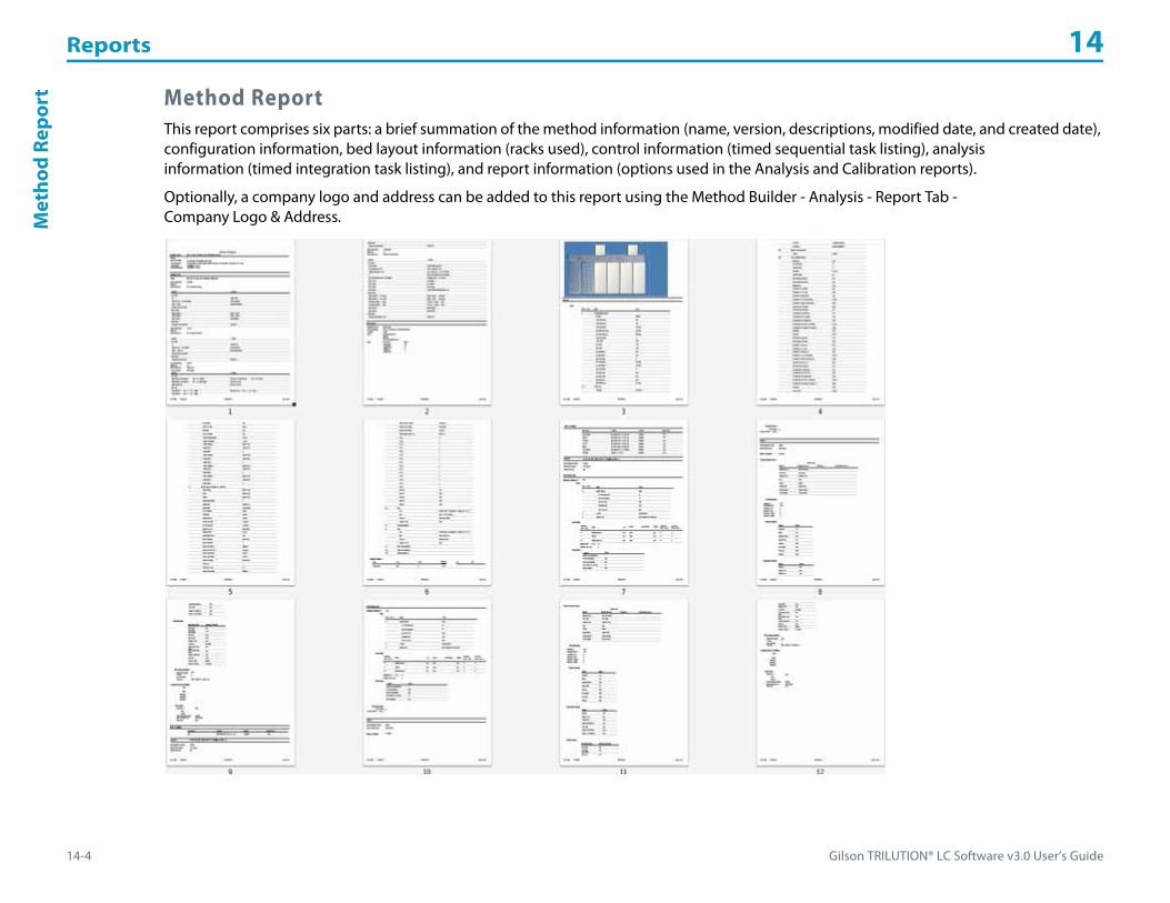
Reports 14
14-4 Gilson TRILUTION® LC Software v3.0 User’s Guide
Met
hod
Repo
rt Method ReportThis report comprises six parts: a brief summation of the method information (name, version, descriptions, modified date, and created date), configuration information, bed layout information (racks used), control information (timed sequential task listing), analysis information (timed integration task listing), and report information (options used in the Analysis and Calibration reports).
Optionally, a company logo and address can be added to this report using the Method Builder - Analysis - Report Tab - Company Logo & Address.
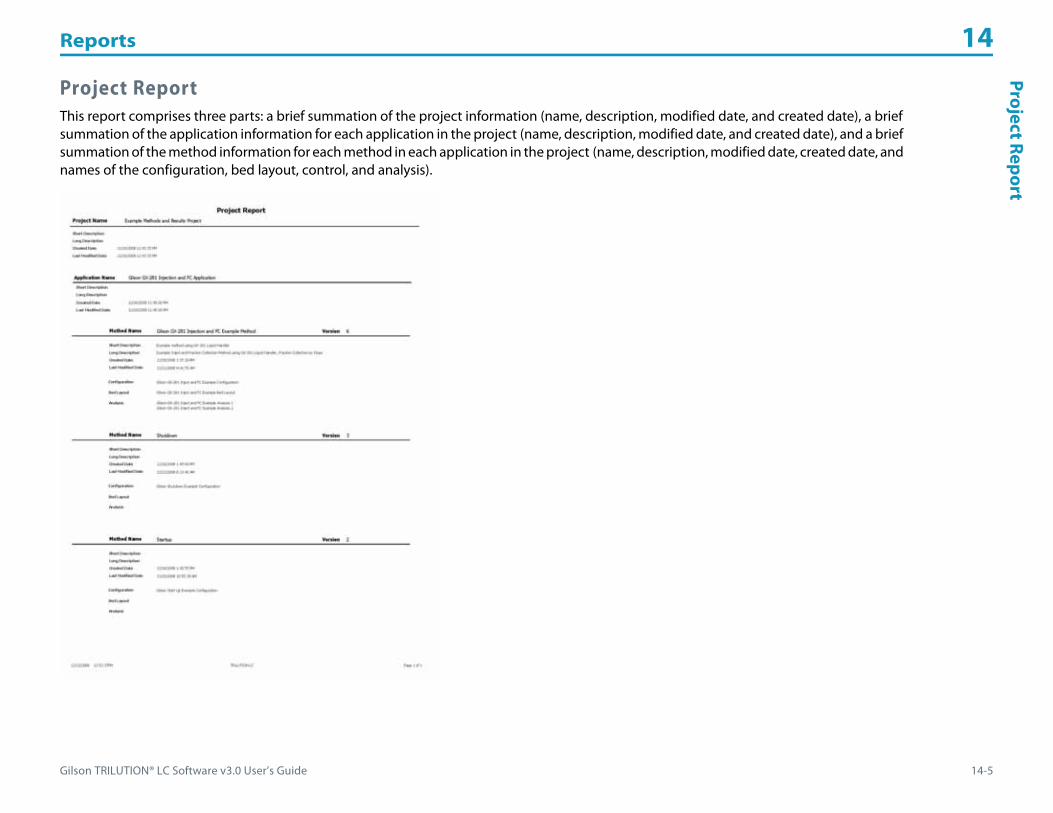
Gilson TRILUTION® LC Software v3.0 User’s Guide 14-5
Reports 14Project Report
Project ReportThis report comprises three parts: a brief summation of the project information (name, description, modified date, and created date), a brief summation of the application information for each application in the project (name, description, modified date, and created date), and a brief summation of the method information for each method in each application in the project (name, description, modified date, created date, and names of the configuration, bed layout, control, and analysis).

Reports 14
14-6 Gilson TRILUTION® LC Software v3.0 User’s Guide
Run
Repo
rt Run ReportThis report comprises five parts: a brief summation of the application run information (project name, application name, run name, run date, run by), sample list details (including values for variables) captured at the end of the run, initial volumes, fraction re-injection criteria, and minimum fraction sites criteria.
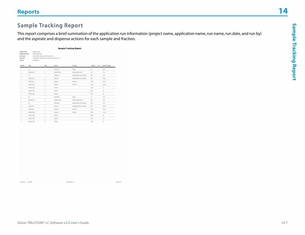
Gilson TRILUTION® LC Software v3.0 User’s Guide 14-7
Reports 14Sam
ple Tracking Report
Sample Tracking ReportThis report comprises a brief summation of the application run information (project name, application name, run name, run date, and run by) and the aspirate and dispense actions for each sample and fraction.

Reports 14
14-8 Gilson TRILUTION® LC Software v3.0 User’s Guide
Ana
lysi
s Re
port Analysis Report
This report comprises five parts: Annotation (includes optionally a heading, listing of the analysis tasks, listing of the control tasks, details about the data channel settings, the peak table, a listing of the control error conditions, and a listing of the analysis error conditions), Graph (chromatogram), Spectrum (only if using a diode array or MS detector), Sample Table (user-specified column contents, may include custom calculations), and Run Variables (a listing of values for all variables used in the application run). Each part is optional and can be omitted by clearing its check box on the Method Builder|Analysis|Report tab. Optionally, a company logo and address can be added to this report using the Method Builder - Analysis - Report Tab - Company Logo & Address.
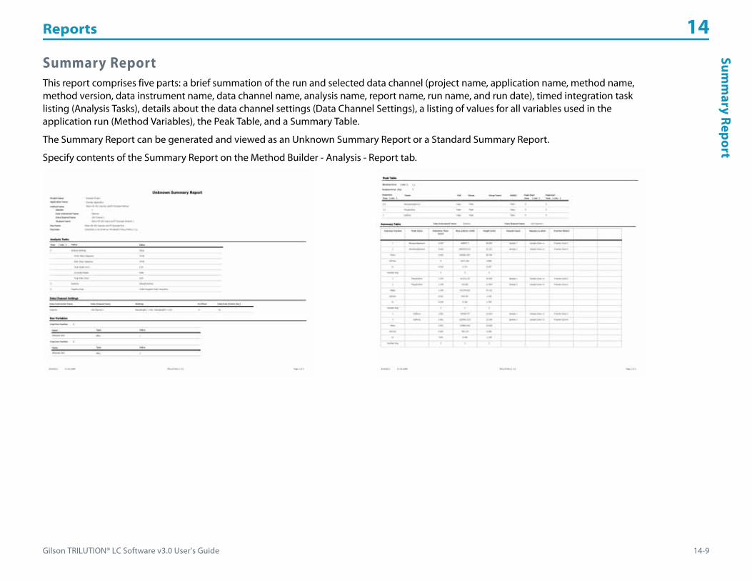
Gilson TRILUTION® LC Software v3.0 User’s Guide 14-9
Reports 14Sum
mary Report
Summary ReportThis report comprises five parts: a brief summation of the run and selected data channel (project name, application name, method name, method version, data instrument name, data channel name, analysis name, report name, run name, and run date), timed integration task listing (Analysis Tasks), details about the data channel settings (Data Channel Settings), a listing of values for all variables used in the application run (Method Variables), the Peak Table, and a Summary Table.
The Summary Report can be generated and viewed as an Unknown Summary Report or a Standard Summary Report.
Specify contents of the Summary Report on the Method Builder - Analysis - Report tab.

Reports 14
14-10 Gilson TRILUTION® LC Software v3.0 User’s Guide
Calib
rati
on R
epor
t Calibration ReportThis report comprises seven parts: Annotation (includes optionally a heading, listing of the analysis tasks, listing of the control tasks, details about the data channel settings, the peak table, a listing of the control error conditions, and a listing of the analysis error conditions), Graph (chromatogram), Sample Table (user-specified column contents, may include custom calculations), and Run Variables (a listing of values for all variables used in the application run), Calibration Plot (the calibration curve data generated by the standards), and Calibration Plot Table (user-specified column contents for standards and controls, may include custom calculations).
The Calibration Report can be generated and viewed for each peak.
Specify contents of the Calibration Report on the Method Builder - Analysis - Report tab.
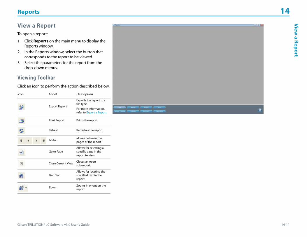
Gilson TRILUTION® LC Software v3.0 User’s Guide 14-11
Reports 14View
a Report
View a ReportTo open a report:
1 Click Reports on the main menu to display the Reports window.
2 In the Reports window, select the button that corresponds to the report to be viewed.
3 Select the parameters for the report from the drop-down menus.
Viewing ToolbarClick an icon to perform the action described below.
Icon Label Description
Export Report
Exports the report to a file type.
For more information, refer to Export a Report.
Print Report Prints the report.
Refresh Refreshes the report.
Go to... Moves between the pages of the report
Go to PageAllows for selecting a specific page in the report to view.
Close Current View Closes an open sub-report.
Find TextAllows for locating the specified text in the report.
Zoom Zooms in or out on the report.

Reports 14
14-12 Gilson TRILUTION® LC Software v3.0 User’s Guide
Expo
rt a
Rep
ort Export a Report
1 On the Reports window, click the Export ( ) button to display the Export Report window.2 Select a destination folder so that it appears in the Save in box.3 Type a file name into the File name box.4 Select the file type from the Save as type box, by clicking on the down arrow and then selecting the format.5 Click Save to save the document. A message box will indicate when the export has completed.

Gilson TRILUTION® LC Software v3.0 User’s Guide A-1
List of Tasks A
Gilson supplies read-only tasks for the instruments listed on the next page. For an alphabetical listing of tasks, refer to All Tasks (in alphabetical order).
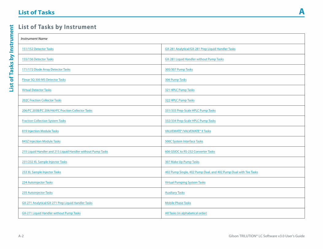
List of Tasks A
A-2 Gilson TRILUTION® LC Software v3.0 User’s Guide
List
of T
asks
by
Inst
rum
ent List of Tasks by Instrument
Instrument Name
151/152 Detector Tasks GX-281 Analytical/GX-281 Prep Liquid Handler Tasks
155/156 Detector Tasks GX-281 Liquid Handler without Pump Tasks
171/172 Diode Array Detector Tasks 305/307 Pump Tasks
Flexar SQ 300 MS Detector Tasks 306 Pump Tasks
Virtual Detector Tasks 321 HPLC Pump Tasks
202C Fraction Collector Tasks 322 HPLC Pump Tasks
206/FC 203B/FC 204/PREPFC Fraction Collector Tasks 331/333 Prep-Scale HPLC Pump Tasks
Fraction Collection System Tasks 332/334 Prep-Scale HPLC Pump Tasks
819 Injection Module Tasks VALVEMATE®/VALVEMATE® II Tasks
845Z Injection Module Tasks 506C System Interface Tasks
215 Liquid Handler and 215 Liquid Handler without Pump Tasks 606 GSIOC to RS-232 Converter Tasks
231/232 XL Sample Injector Tasks 307 Make Up Pump Tasks
233 XL Sample Injector Tasks 402 Pump Single, 402 Pump Dual, and 402 Pump Dual with Tee Tasks
234 Autoinjector Tasks Virtual Pumping System Tasks
235 Autoinjector Tasks Auxiliary Tasks
GX-271 Analytical/GX-271 Prep Liquid Handler Tasks Mobile Phase Tasks
GX-271 Liquid Handler without Pump Tasks All Tasks (in alphabetical order)
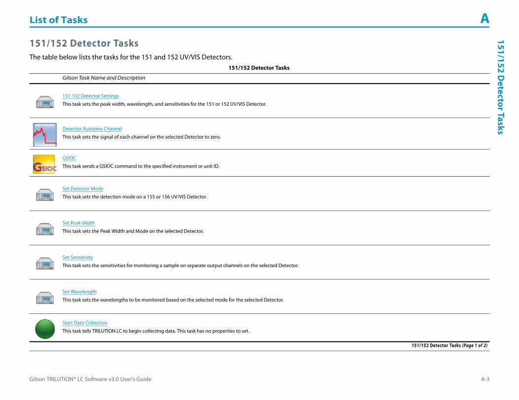
Gilson TRILUTION® LC Software v3.0 User’s Guide A-3
List of Tasks A151/152 D
etector Tasks
151/152 Detector TasksThe table below lists the tasks for the 151 and 152 UV/VIS Detectors.
151/152 Detector Tasks
Gilson Task Name and Description
151 152 Detector Settings
This task sets the peak width, wavelength, and sensitivities for the 151 or 152 UV/VIS Detector.
Detector Autozero Channel
This task sets the signal of each channel on the selected Detector to zero.
GSIOC
This task sends a GSIOC command to the specified instrument or unit ID.
Set Detector Mode
This task sets the detection mode on a 155 or 156 UV/VIS Detector.
Set Peak Width
This task sets the Peak Width and Mode on the selected Detector.
Set Sensitivity
This task sets the sensitivities for monitoring a sample on separate output channels on the selected Detector.
Set Wavelength
This task sets the wavelengths to be monitored based on the selected mode for the selected Detector.
Start Data Collection
This task tells TRILUTION LC to begin collecting data. This task has no properties to set.
151/152 Detector Tasks (Page 1 of 2)

List of Tasks A
A-4 Gilson TRILUTION® LC Software v3.0 User’s Guide
151/
152
Det
ecto
r Tas
ks
Stop Data Collection
This task tells TRILUTION LC to stop collecting data. This task has no properties to set.
Turn Lamp Off
This task turns off power to the lamps while maintaining power to the Detector.
Turn Lamp On
This task turns the UV and visible lamps on for the specified Detector.
Write to Display
This task displays a message in the front panel display of the selected instrument.
Note: Write to Display is only available for the 151 Detector, as the 152 Detector does not have a front panel display.
151/152 Detector Tasks (Continued)
Gilson Task Name and Description
151/152 Detector Tasks (Page 2 of 2)
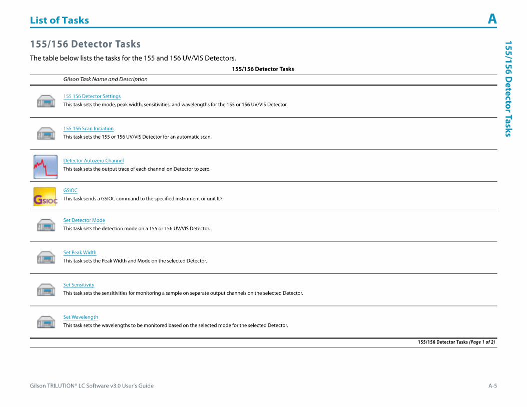
Gilson TRILUTION® LC Software v3.0 User’s Guide A-5
List of Tasks A155/156 D
etector Tasks
155/156 Detector TasksThe table below lists the tasks for the 155 and 156 UV/VIS Detectors.
155/156 Detector Tasks
Gilson Task Name and Description
155 156 Detector Settings
This task sets the mode, peak width, sensitivities, and wavelengths for the 155 or 156 UV/VIS Detector.
155 156 Scan Initiation
This task sets the 155 or 156 UV/VIS Detector for an automatic scan.
Detector Autozero Channel
This task sets the output trace of each channel on Detector to zero.
GSIOC
This task sends a GSIOC command to the specified instrument or unit ID.
Set Detector Mode
This task sets the detection mode on a 155 or 156 UV/VIS Detector.
Set Peak Width
This task sets the Peak Width and Mode on the selected Detector.
Set Sensitivity
This task sets the sensitivities for monitoring a sample on separate output channels on the selected Detector.
Set Wavelength
This task sets the wavelengths to be monitored based on the selected mode for the selected Detector.
155/156 Detector Tasks (Page 1 of 2)

List of Tasks A
A-6 Gilson TRILUTION® LC Software v3.0 User’s Guide
155/
156
Det
ecto
r Tas
ks
Start Data Collection
This task tells TRILUTION LC to begin collecting data. This task has no properties to set.
Stop Data Collection
This task tells TRILUTION LC to stop collecting data. This task has no properties to set.
Turn Lamp Off
This task turns off power to the lamps while maintaining power to the Detector.
Turn Lamp On
This task turns the UV and visible lamps on for the specified Detector.
Write to Display
This task displays a message in the front panel display of the selected instrument.
Note: Write to Display is only available for the 155 Detector, as the 156 Detector does not have a front panel display
155/156 Detector Tasks (Continued)
Gilson Task Name and Description
155/156 Detector Tasks (Page 2 of 2)

Gilson TRILUTION® LC Software v3.0 User’s Guide A-7
List of Tasks A171/172 D
iode Array D
etector Tasks
171/172 Diode Array Detector TasksThe table below lists the tasks for the 171 and 172 Diode Array Detectors.
171/172 Diode Array Detector Tasks
Gilson Task Name and Description
171 172 Detector Settings
This task sets the DAD wavelengths and bandwidths to be monitored based on each selected Channel for the selected Detector.
Contact Open - Close
This task opens and powers off, closes and powers on, or pulses the specified output contact on a specified instrument.
Start Data Collection
This task tells TRILUTION LC to begin collecting data. This task has no properties to set.
Stop Data Collection
This task tells TRILUTION LC to stop collecting data. This task has no properties to set.
Turn Lamp Off
This task turns off power to the lamps while maintaining power to the Detector.
Turn Lamp On
This task turns the UV and visible lamps on for the specified Detector.
Wait for Contact
This task initiates a wait in the method until any contact state change or a user-specified contact state change for the specified contact is detected. Sync to the end of the task (using a Sync task) to prevent other tasks in the method from executing during the wait.
171/172 Diode Array Detector Tasks

List of Tasks A
A-8 Gilson TRILUTION® LC Software v3.0 User’s Guide
Flex
ar S
Q 3
00 M
S D
etec
tor T
asks Flexar SQ 300 MS Detector Tasks
The table below lists the tasks for the Flexar SQ 300 MS Detector.Flexar SQ 300 MS Detector Tasks
Gilson Task Name and Description
Mass Spec Auto Tune
This task tunes the Flexar SQ 300 MS Detector across a specified mass range using a specified tune mix.
Run this task using manual control (NOT as part of a method).
Mass Spec Check Tune
This task verifies that the Flexar SQ 300 MS Detector is tuned across a specified mass range using a specified tune mix.
Run this task using manual control (NOT as part of a method).
Mass Spec Single Quad APCI Settings
This task changes the corona currents used when collecting data.
Mass Spec Single Quad Settings
This task sets the data collection parameters for each selected channel for the Flexar SQ 300 MS Detector.
Mass Spec Single Quad Standby
This task puts the Flexar SQ 300 MS Detector in standby.
Mass Spec Single Quad Start Up
This task sets the dry gas flow and temperature, the nebulizer gas pressure, and the APCI vaporizer temperature (if applicable) on the Flexar SQ 300 MS Detector.
Start Data Collection
This task tells TRILUTION LC to begin collecting data. This task has no properties to set.
Stop Data Collection
This task tells TRILUTION LC to stop collecting data. This task has no properties to set.
Flexar SQ 300 MS Detector Tasks

Gilson TRILUTION® LC Software v3.0 User’s Guide A-9
List of Tasks AVirtual D
etector Tasks
Virtual Detector TasksThe table below lists the tasks for the Virtual Detector.
Virtual Detector Tasks
Gilson Task Name and Description
Start Data Collection
This task tells TRILUTION LC to begin collecting data. This task has no properties to set.
Stop Data Collection
This task tells TRILUTION LC to stop collecting data. This task has no properties to set.
Virtual Detector Tasks

List of Tasks A
A-10 Gilson TRILUTION® LC Software v3.0 User’s Guide
202C
Fra
ctio
n Co
llect
or T
asks 202C Fraction Collector Tasks
The table below lists the tasks for the 202C Fraction Collector.202C Fraction Collector Tasks
Gilson Task Name and Description
Fraction Collection Settings
This task sets all parameters for fraction collection.
Fraction Collection Valve Rinse
This task rinses the fraction collection valve for a user-specified duration.
GSIOC
This task sends a GSIOC command to the specified instrument or unit ID.
Home Fraction Collector
This task homes the specified Fraction Collector.
Set Fraction Site
This task identifies where fraction collection will begin for an injected sample.
Set Multiple Bed Collection
This task is used to set the fraction site when multiple fraction collectors are being used.
Set Non Peak Per Tube
This task sets parameters for collecting non-peaks.
Set Peak Level
This task sets the parameters for fraction collection by level.
Set Peak Per Tube
This task sets parameters for collecting peaks.
202C Fraction Collector Tasks (Page 1 of 2)

Gilson TRILUTION® LC Software v3.0 User’s Guide A-11
List of Tasks A202C Fraction Collector Tasks
Set Peak Slope
This task sets the parameters for fraction collection by slope.
Start Fraction Collection
This task tells TRILUTION LC to begin collecting fractions. This task has no properties to set.
Stop Fraction Collection
This task tells TRILUTION LC to stop collecting fractions. This task has no properties to set.
202C Fraction Collector Tasks (Continued)
Gilson Task Name and Description
202C Fraction Collector Tasks (Page 2 of 2)
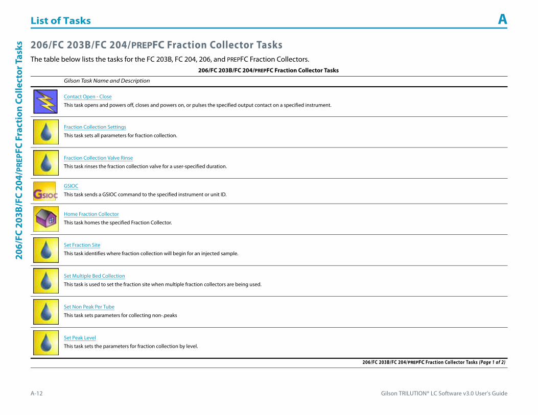
List of Tasks A
A-12 Gilson TRILUTION® LC Software v3.0 User’s Guide
206/
FC 2
03B/
FC 2
04/P
REPF
C Fr
acti
on C
olle
ctor
Tas
ks 206/FC 203B/FC 204/PREPFC Fraction Collector TasksThe table below lists the tasks for the FC 203B, FC 204, 206, and PREPFC Fraction Collectors.
206/FC 203B/FC 204/PREPFC Fraction Collector Tasks
Gilson Task Name and Description
Contact Open - Close
This task opens and powers off, closes and powers on, or pulses the specified output contact on a specified instrument.
Fraction Collection Settings
This task sets all parameters for fraction collection.
Fraction Collection Valve Rinse
This task rinses the fraction collection valve for a user-specified duration.
GSIOC
This task sends a GSIOC command to the specified instrument or unit ID.
Home Fraction Collector
This task homes the specified Fraction Collector.
Set Fraction Site
This task identifies where fraction collection will begin for an injected sample.
Set Multiple Bed Collection
This task is used to set the fraction site when multiple fraction collectors are being used.
Set Non Peak Per Tube
This task sets parameters for collecting non-.peaks
Set Peak Level
This task sets the parameters for fraction collection by level.
206/FC 203B/FC 204/PREPFC Fraction Collector Tasks (Page 1 of 2)
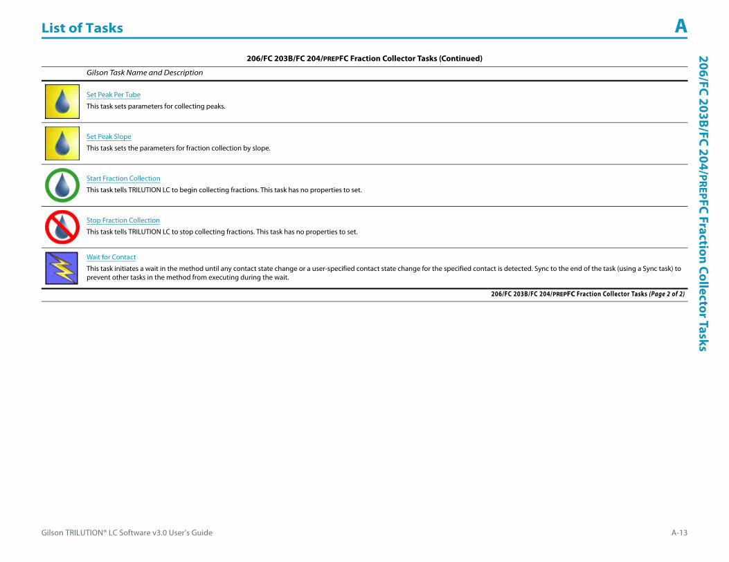
Gilson TRILUTION® LC Software v3.0 User’s Guide A-13
List of Tasks A206/FC 203B/FC 204/PREPFC Fraction Collector Tasks
Set Peak Per Tube
This task sets parameters for collecting peaks.
Set Peak Slope
This task sets the parameters for fraction collection by slope.
Start Fraction Collection
This task tells TRILUTION LC to begin collecting fractions. This task has no properties to set.
Stop Fraction Collection
This task tells TRILUTION LC to stop collecting fractions. This task has no properties to set.
Wait for Contact
This task initiates a wait in the method until any contact state change or a user-specified contact state change for the specified contact is detected. Sync to the end of the task (using a Sync task) to prevent other tasks in the method from executing during the wait.
206/FC 203B/FC 204/PREPFC Fraction Collector Tasks (Continued)
Gilson Task Name and Description
206/FC 203B/FC 204/PREPFC Fraction Collector Tasks (Page 2 of 2)

List of Tasks A
A-14 Gilson TRILUTION® LC Software v3.0 User’s Guide
Frac
tion
Col
lect
ion
Syst
em T
asks Fraction Collection System Tasks
The table below lists the tasks for the Fraction Collection System.Fraction Collection System Tasks
Gilson Task Name and Description
Fraction Collection Settings
This task sets all parameters for fraction collection.
Fraction Collection Valve Rinse
This task rinses the fraction collection valve for a user-specified duration.
GSIOC
This task sends a GSIOC command to the specified instrument or unit ID.
Home Fraction Collector
This task homes the specified Fraction Collector.
Set Fraction Site
This task identifies where fraction collection will begin for an injected sample.
Set Multiple Bed Collection
This task is used to set the fraction site when multiple fraction collectors are being used.
Set Non Peak Per Tube
This task sets parameters for collecting non-peaks.
Set Peak Level
This task sets the parameters for fraction collection by level.
Fraction Collection System Tasks (Page 1 of 2)

Gilson TRILUTION® LC Software v3.0 User’s Guide A-15
List of Tasks AFraction Collection System
Tasks
Set Peak Per Tube
This task sets parameters for collecting peaks.
Set Peak Slope
This task sets the parameters for fraction collection by slope.
Start Fraction Collection
This task tells TRILUTION LC to begin collecting fractions. This task has no properties to set.
Stop Fraction Collection
This task tells TRILUTION LC to stop collecting fractions. This task has no properties to set.
Fraction Collection System Tasks (Continued)
Gilson Task Name and Description
Fraction Collection System Tasks (Page 2 of 2)

List of Tasks A
A-16 Gilson TRILUTION® LC Software v3.0 User’s Guide
819
Inje
ctio
n M
odul
e Ta
sks 819 Injection Module Tasks
The table below lists tasks for the 819 Injection Module.819 Injection Module Tasks
Gilson Task Name and Description
215 819 Low Volume Partial Loop Injection
This task performs a partial loop injection using a push volume from the reservoir to push the injection volume into the sample loop.
215 819 Partial Loop Injection
This task performs a partial loop injection.
215 819 Prep Injection with Collection
This task is used when doing injection and fraction collection on the same bed. It performs a partial loop injection using a push volume from the reservoir to push the injection volume into the sample loop and includes a rinse of the fraction collection valve.
GSIOC
This task sends a GSIOC command to the specified instrument or unit ID.
Injection Valve Position
This task sets the injection valve position on the Injector to either LOAD or INJECT.
819 Injection Module Tasks
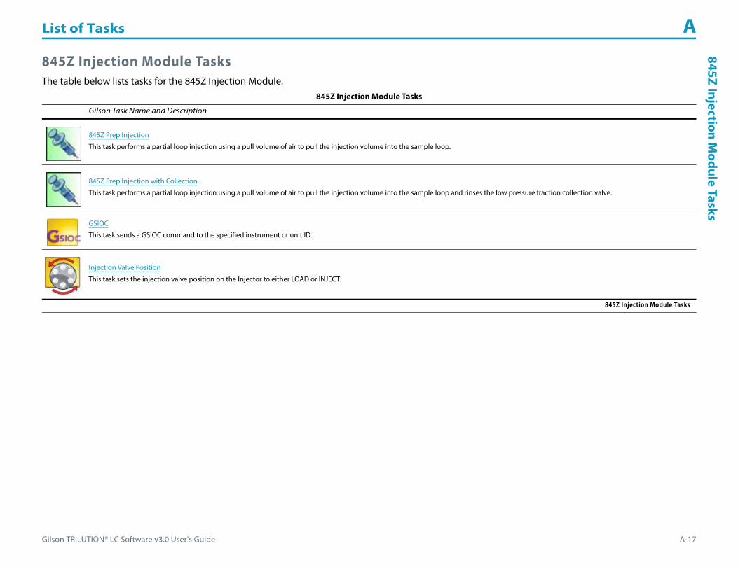
Gilson TRILUTION® LC Software v3.0 User’s Guide A-17
List of Tasks A845Z Injection M
odule Tasks
845Z Injection Module TasksThe table below lists tasks for the 845Z Injection Module.
845Z Injection Module Tasks
Gilson Task Name and Description
845Z Prep Injection
This task performs a partial loop injection using a pull volume of air to pull the injection volume into the sample loop.
845Z Prep Injection with Collection
This task performs a partial loop injection using a pull volume of air to pull the injection volume into the sample loop and rinses the low pressure fraction collection valve.
GSIOC
This task sends a GSIOC command to the specified instrument or unit ID.
Injection Valve Position
This task sets the injection valve position on the Injector to either LOAD or INJECT.
845Z Injection Module Tasks

List of Tasks A
A-18 Gilson TRILUTION® LC Software v3.0 User’s Guide
215
Liqu
id H
andl
er a
nd 2
15 L
iqui
d H
andl
er w
itho
ut P
ump
Task
s 215 Liquid Handler and 215 Liquid Handler without Pump TasksThe table below lists the tasks for the 215 Liquid Handler and 215 Liquid Handler without Pump.
215 Liquid Handler and 215 Liquid Handler without Pump Tasks
Gilson Task Name and Description
215 819 Low Volume Partial Loop Injection
This task performs a partial loop injection using a push volume from the reservoir to push the injection volume into the sample loop.
215 819 Partial Loop Injection
This task performs a partial loop injection.
215 819 Prep Injection with Collection
This task is used when doing injection and fraction collection on the same bed. It performs a partial loop injection using a push volume from the reservoir to push the injection volume into the sample loop and includes a rinse of the fraction collection valve.
845Z Prep Injection
This task performs a partial loop injection using a pull volume of air to pull the injection volume into the sample loop.
845Z Prep Injection with Collection
This task performs a partial loop injection using a pull volume of air to pull the injection volume into the sample loop and also rinses the low pressure fraction collection valve.
Add Diluent
This task aspirates the specified amount of liquid (Diluent Source) from the reservoir or the probe and then dispenses to the wells of the sample zone and then mixes with liquid or air.
Aspirate
This task aspirates an air gap or the specified volume of liquid (Aspirate Volume) from the reservoir or probe and must be synchronized with the Move to Sample Location task to move the probe to the well before aspirating liquid.
Collection and Travel Depth
This task customizes probe (used as a dispense needle) movement during fraction collection.
215 Liquid Handler and 215 Liquid Handler without Pump Tasks (Page 1 of 5)
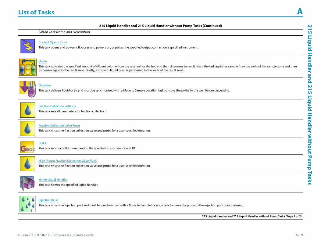
Gilson TRILUTION® LC Software v3.0 User’s Guide A-19
List of Tasks A215 Liquid H
andler and 215 Liquid Handler w
ithout Pump Tasks
Contact Open - Close
This task opens and powers off, closes and powers on, or pulses the specified output contact on a specified instrument.
Dilute
This task aspirates the specified amount of diluent volume from the reservoir or the bed and then dispenses to result. Next, the task aspirates sample from the wells of the sample zone and then dispenses again to the result zone. Finally, a mix with liquid or air is performed in the wells of the result zone.
Dispense
This task delivers liquid or air and must be synchronized with a Move to Sample Location task to move the probe to the well before dispensing.
Fraction Collection Settings
This task sets all parameters for fraction collection.
Fraction Collection Valve Rinse
This task rinses the fraction collection valve and probe for a user-specified duration.
GSIOC
This task sends a GSIOC command to the specified instrument or unit ID.
High Mount Fraction Collection Valve Flush
This task rinses the fraction collection valve and probe for a user-specified duration.
Home Liquid Handler
This task homes the specified liquid handler.
Injection Rinse
This task rinses the injection port and must be synchronized with a Move to Sample Location task to move the probe to the injection port prior to rinsing.
215 Liquid Handler and 215 Liquid Handler without Pump Tasks (Continued)
Gilson Task Name and Description
215 Liquid Handler and 215 Liquid Handler without Pump Tasks (Page 2 of 5)
List of Tasks A
A-20 Gilson TRILUTION® LC Software v3.0 User’s Guide
215
Liqu
id H
andl
er a
nd 2
15 L
iqui
d H
andl
er w
itho
ut P
ump
Task
s
Inside Rinse
This task moves to the rinse station and then rinses the inside of the probe.
Mix with Air
This task aspirates air and then dispenses it into a well a specified number of times.
Mix with Liquid
This task aspirates liquid and then dispenses it into a well a specified number of times.
Move to Sample Location
This task moves the probe to a specified height in a specified well in a specified zone.
Outside Rinse
This task moves to the rinse station and then rinses the outside of the probe.
Prime Dilutor
This task primes the dilutor. It aspirates the syringe capacity from the reservoir and then dispenses to the specified wells in the specified zone for the number of cycles.
Set Fraction Site
This task identifies where fraction collection will begin for an injected sample.
Set Multiple Bed Collection
This task is used to set the fraction site when multiple fraction collectors are being used.
215 Liquid Handler and 215 Liquid Handler without Pump Tasks (Continued)
Gilson Task Name and Description
215 Liquid Handler and 215 Liquid Handler without Pump Tasks (Page 3 of 5)

Gilson TRILUTION® LC Software v3.0 User’s Guide A-21
List of Tasks A215 Liquid H
andler and 215 Liquid Handler w
ithout Pump Tasks
Set Non Peak Per Tube
This task sets parameters for collecting non-peaks.
Set Peak Level
This task sets the parameters for fraction collection by level.
Set Peak Per Tube
This task sets parameters for collecting peaks.
Set Peak Slope
This task sets the parameters for fraction collection by slope.
Start Fraction Collection
This task tells TRILUTION LC to begin collecting fractions. This task has no properties to set.
Stop Fraction Collection
This task tells TRILUTION LC to stop collecting fractions. This task has no properties to set.
Transfer
This task aspirates the specified volume of liquid (Source Volume) from the probe and then dispenses the volume to the wells of the result zone.
215 Liquid Handler and 215 Liquid Handler without Pump Tasks (Continued)
Gilson Task Name and Description
215 Liquid Handler and 215 Liquid Handler without Pump Tasks (Page 4 of 5)

List of Tasks A
A-22 Gilson TRILUTION® LC Software v3.0 User’s Guide
215
Liqu
id H
andl
er a
nd 2
15 L
iqui
d H
andl
er w
itho
ut P
ump
Task
s
Voltage On - Off
This task opens and powers off or closes and powers on a specified contact on a specified liquid handler.
Wait for Contact
This task initiates a wait in the method until any contact state change or a user-specified contact state change for the specified contact is detected. Sync to the end of the task (using a Sync task) to prevent other tasks in the method from executing during the wait.
Write to Display
This task displays a message in the front panel display of the selected instrument.
215 Liquid Handler and 215 Liquid Handler without Pump Tasks (Continued)
Gilson Task Name and Description
215 Liquid Handler and 215 Liquid Handler without Pump Tasks (Page 5 of 5)

Gilson TRILUTION® LC Software v3.0 User’s Guide A-23
List of Tasks A231/232
XLSam
pleInjector Tasks
231/232 XL Sample Injector TasksThe table below lists the tasks for the 231 and 232 XL Sample Injectors.
231/232 XL Sample Injector Tasks
Gilson Task Name and Description
Add Diluent
This task aspirates the specified amount of liquid (Diluent Source) from the reservoir or the probe and then dispenses to the wells of the sample zone and then mixes with liquid or air.
Aspirate
This task aspirates an air gap or the specified volume of liquid (Aspirate Volume) from the reservoir or probe and must be synchronized with the Move to Sample Location task to move the probe to the well before aspirating liquid.
Contact Open - Close
This task opens and powers off, closes and powers on, or pulses the specified output contact on a specified instrument.
Dilute
This task aspirates the specified amount of diluent volume from the reservoir or the bed and then dispenses to result. Next, the task aspirates sample from the wells of the sample zone and then dispenses again to the result zone. Finally, a mix with liquid or air is performed in the wells of the result zone.
Dispense
This task delivers liquid or air and must be synchronized with a Move to Sample Location task to move the probe to the well before dispensing.
GSIOC
This task sends a GSIOC command to the specified instrument or unit ID.
Home Liquid Handler
This task homes the specified liquid handler.
Injection Rinse
This task rinses the injection port and must be synchronized with a Move to Sample Location task to move the probe to the injection port prior to rinsing.
231/232 XL Sample Injector Tasks (Page 1 of 3)
List of Tasks A
A-24 Gilson TRILUTION® LC Software v3.0 User’s Guide
231/
232
XLSa
mpl
eIn
ject
or T
asks
Injection Valve Position
This task sets the injection valve position on the Injector to either LOAD or INJECT.
Inside Rinse
This task moves to the rinse station and then rinses the inside of the probe.
Mix with Air
This task aspirates air and then dispenses it into a well a specified number of times.
Mix with Liquid
This task aspirates liquid and then dispenses it into a well a specified number of times.
Move to Sample Location
This task moves the probe to a specified height in a specified well in a specified zone.
Outside Rinse
This task moves to the rinse station and then rinses the outside of the probe.
Prime Dilutor
This task primes the dilutor. It aspirates the syringe capacity from the reservoir and then dispenses to the specified wells in the specified zone for the number of cycles.
Transfer
This task aspirates the specified volume of liquid (Source Volume) from the probe and then dispenses the volume to the wells of the result zone.
Wait for Contact
This task initiates a wait in the method until any contact state change or a user-specified contact state change for the specified contact is detected. Sync to the end of the task (using a Sync task) to prevent other tasks in the method from executing during the wait.
231/232 XL Sample Injector Tasks (Continued)
Gilson Task Name and Description
231/232 XL Sample Injector Tasks (Page 2 of 3)

Gilson TRILUTION® LC Software v3.0 User’s Guide A-25
List of Tasks A231/232
XLSam
pleInjector Tasks
XL Low Volume Partial Loop Injection
This task performs a partial loop injection using a push volume from the reservoir to push the injection volume into the sample loop.
XL Partial Loop Injection
This task performs a partial loop injection.
XL Total Loop Injection
This task performs a total loop injection.
231/232 XL Sample Injector Tasks (Continued)
Gilson Task Name and Description
231/232 XL Sample Injector Tasks (Page 3 of 3)

List of Tasks A
A-26 Gilson TRILUTION® LC Software v3.0 User’s Guide
233
XLSa
mpl
eIn
ject
or T
asks 233 XL Sample Injector Tasks
The table below lists the tasks for the 233 XL Sample Injector.233 XL Sample Injector Tasks
Gilson Task Name and Description
233 XL Prep Injection with Collection
This task performs a partial loop injection using a push volume from the reservoir to push the injection volume into the sample loop and includes a rinse of the fraction collection valve.
Add Diluent
This task aspirates the specified amount of liquid (Diluent Source) from the reservoir or the probe and then dispenses to the wells of the sample zone and then mixes with liquid or air.
Aspirate
This task aspirates an air gap or the specified volume of liquid (Aspirate Volume) from the reservoir or probe and must be synchronized with the Move to Sample Location task to move the probe to the well before aspirating liquid.
Collection and Travel Depth
This task customizes probe (used as a dispense needle) movement during fraction collection.
Contact Open - Close
This task opens and powers off, closes and powers on, or pulses the specified output contact on a specified instrument.
Dilute
This task aspirates the specified amount of diluent volume from the reservoir or the bed and then dispenses to result. Next, the task aspirates sample from the wells of the sample zone and then dispenses again to the result zone. Finally, a mix with liquid or air is performed in the wells of the result zone.
Dispense
This task delivers liquid or air and must be synchronized with a Move to Sample Location task to move the probe to the well before dispensing.
Fraction Collection Settings
This task sets all parameters for fraction collection.
233 XL Sample Injector Tasks (Page 1 of 4)
Gilson TRILUTION® LC Software v3.0 User’s Guide A-27
List of Tasks A233
XLSam
pleInjector Tasks
Fraction Collection Valve Rinse
This task rinses the fraction collection valve for a user-specified duration.
GSIOC
This task sends a GSIOC command to the specified instrument or unit ID.
Home Fraction Collector
This task homes the specified Fraction Collector.
Home Liquid Handler
This task homes the specified liquid handler.
Injection Rinse
This task rinses the injection port and must be synchronized with a Move to Sample Location task to move the probe to the injection port prior to rinsing.
Injection Valve Position
This task sets the injection valve position on the Injector to either LOAD or INJECT.
Inside Rinse
This task moves to the rinse station and then rinses the inside of the probe.
Mix with Air
This task aspirates air and then dispenses it into a well a specified number of times.
Mix with Liquid
This task aspirates liquid and then dispenses it into a well a specified number of times.
233 XL Sample Injector Tasks (Continued)
Gilson Task Name and Description
233 XL Sample Injector Tasks (Page 2 of 4)

List of Tasks A
A-28 Gilson TRILUTION® LC Software v3.0 User’s Guide
233
XLSa
mpl
eIn
ject
or T
asks
Move to Sample Location
This task moves the probe to a specified height in a specified well in a specified zone.
Outside Rinse
This task moves to the rinse station and then rinses the outside of the probe.
Prime Dilutor
This task primes the dilutor. It aspirates the syringe capacity from the reservoir and then dispenses to the specified wells in the specified zone for the number of cycles.
Set Fraction Site
This task identifies where fraction collection will begin for an injected sample.
Set Multiple Bed Collection
This task is used to set the fraction site when multiple fraction collectors are being used.
Set Non Peak Per Tube
This task sets parameters for collecting non-peaks.
Set Peak Level
This task sets the parameters for fraction collection by level.
Set Peak Per Tube
This task sets parameters for collecting peaks.
233 XL Sample Injector Tasks (Continued)
Gilson Task Name and Description
233 XL Sample Injector Tasks (Page 3 of 4)
Gilson TRILUTION® LC Software v3.0 User’s Guide A-29
List of Tasks A233
XLSam
pleInjector Tasks
Set Peak Slope
This task sets the parameters for fraction collection by slope.
Start Fraction Collection
This task tells TRILUTION LC to begin collecting fractions. This task has no properties to set.
Stop Fraction Collection
This task tells TRILUTION LC to stop collecting fractions. This task has no properties to set.
Transfer
This task aspirates the specified volume of liquid (Source Volume) from the probe and then dispenses the volume to the wells of the result zone.
Wait for Contact
This task initiates a wait in the method until any contact state change or a user-specified contact state change for the specified contact is detected. Sync to the end of the task (using a Sync task) to prevent other tasks in the method from executing during the wait.
XL Low Volume Partial Loop Injection
This task performs a partial loop injection using a push volume from the reservoir to push the injection volume into the sample loop.
XL Partial Loop Injection
This task performs a partial loop injection.
XL Total Loop Injection
This task performs a total loop injection.
233 XL Sample Injector Tasks (Continued)
Gilson Task Name and Description
233 XL Sample Injector Tasks (Page 4 of 4)

List of Tasks A
A-30 Gilson TRILUTION® LC Software v3.0 User’s Guide
234
Aut
oinj
ecto
r Tas
ks 234 Autoinjector TasksThe table below lists the tasks for the 234 Autoinjector.
234 Autoinjector Tasks
Gilson Task Name and Description
234 Partial Loop Injection
This task performs a partial loop injection.
234 Total Loop Injection
This task performs a total loop injection.
Add Diluent
This task aspirates the specified amount of liquid (Diluent Source) from the reservoir or the probe and then dispenses to the wells of the sample zone and then mixes with liquid or air.
Aspirate
This task aspirates an air gap or the specified volume of liquid (Aspirate Volume) from the reservoir or probe and must be synchronized with the Move to Sample Location task to move the probe to the well before aspirating liquid.
Contact Open - Close
This task opens and powers off, closes and powers on, or pulses the specified output contact on a specified instrument.
Dilute
This task aspirates the specified amount of diluent volume from the reservoir or the bed and then dispenses to result. Next, the task aspirates sample from the wells of the sample zone and then dispenses again to the result zone. Finally, a mix with liquid or air is performed in the wells of the result zone.
Dispense
This task delivers liquid or air and must be synchronized with a Move to Sample Location task to move the probe to the well before dispensing.
GSIOC
This task sends a GSIOC command to the specified instrument or unit ID.
234 Autoinjector Tasks (Page 1 of 3)
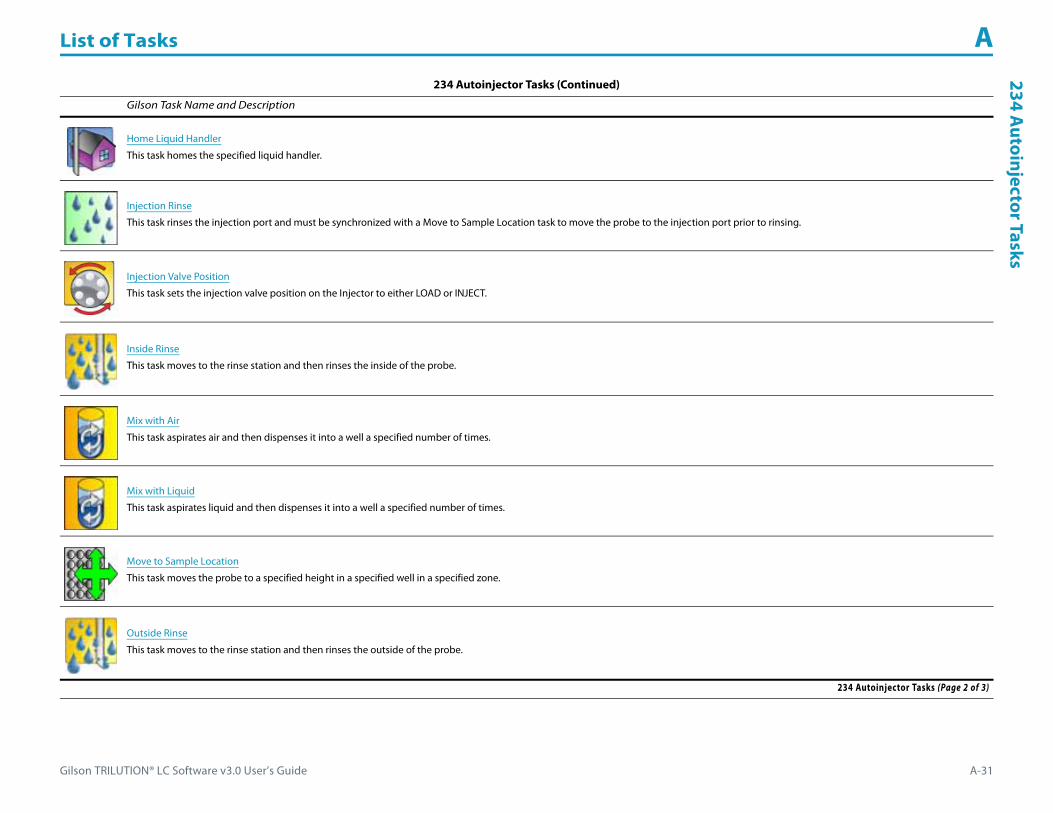
Gilson TRILUTION® LC Software v3.0 User’s Guide A-31
List of Tasks A234 A
utoinjector Tasks
Home Liquid Handler
This task homes the specified liquid handler.
Injection Rinse
This task rinses the injection port and must be synchronized with a Move to Sample Location task to move the probe to the injection port prior to rinsing.
Injection Valve Position
This task sets the injection valve position on the Injector to either LOAD or INJECT.
Inside Rinse
This task moves to the rinse station and then rinses the inside of the probe.
Mix with Air
This task aspirates air and then dispenses it into a well a specified number of times.
Mix with Liquid
This task aspirates liquid and then dispenses it into a well a specified number of times.
Move to Sample Location
This task moves the probe to a specified height in a specified well in a specified zone.
Outside Rinse
This task moves to the rinse station and then rinses the outside of the probe.
234 Autoinjector Tasks (Continued)
Gilson Task Name and Description
234 Autoinjector Tasks (Page 2 of 3)

List of Tasks A
A-32 Gilson TRILUTION® LC Software v3.0 User’s Guide
234
Aut
oinj
ecto
r Tas
ks
Prime Dilutor
This task primes the dilutor. It aspirates the syringe capacity from the reservoir and then dispenses to the specified wells in the specified zone for the number of cycles.
Transfer
This task aspirates the specified volume of liquid (Source Volume) from the probe and then dispenses the volume to the wells of the result zone.
Wait for Contact
This task initiates a wait in the method until any contact state change or a user-specified contact state change for the specified contact is detected. Sync to the end of the task (using a Sync task) to prevent other tasks in the method from executing during the wait.
234 Autoinjector Tasks (Continued)
Gilson Task Name and Description
234 Autoinjector Tasks (Page 3 of 3)

Gilson TRILUTION® LC Software v3.0 User’s Guide A-33
List of Tasks A235 A
utoinjector Tasks
235 Autoinjector TasksThe table below lists the tasks for the 235 Autoinjector.
235 Autoinjector Tasks
Gilson Task Name and Description
235S Partial Loop Injection
This task performs a partial loop injection.
235S Total Loop Injection
This task performs a total loop injection.
235T Injection Rinse
This task is used to rinse the injection port on a 235 Autoinjector with tee injection port.
235T Partial Loop Injection
This task performs a partial loop injection on a 235 Autoinjector with a tee injection port.
235T Total Loop Injection
This task performs a total loop injection on a 235 Autoinjector with tee injection port.
Add Diluent
This task aspirates the specified amount of liquid (Diluent Source) from the reservoir or the probe and then dispenses to the wells of the sample zone and then mixes with liquid or air.
Aspirate
This task aspirates an air gap or the specified volume of liquid (Aspirate Volume) from the reservoir or probe and must be synchronized with the Move to Sample Location task to move the probe to the well before aspirating liquid.
Contact Open - Close
This task opens and powers off, closes and powers on, or pulses the specified output contact on a specified instrument.
235 Autoinjector Tasks (Page 1 of 3)
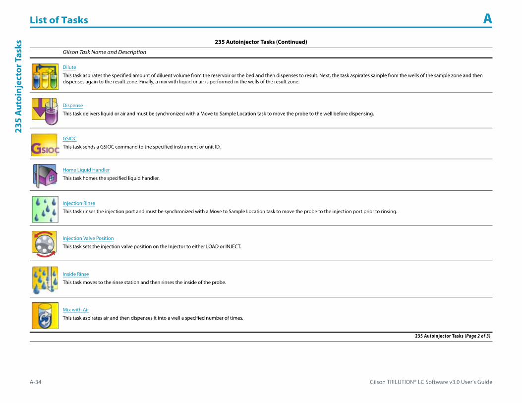
List of Tasks A
A-34 Gilson TRILUTION® LC Software v3.0 User’s Guide
235
Aut
oinj
ecto
r Tas
ks
Dilute
This task aspirates the specified amount of diluent volume from the reservoir or the bed and then dispenses to result. Next, the task aspirates sample from the wells of the sample zone and then dispenses again to the result zone. Finally, a mix with liquid or air is performed in the wells of the result zone.
Dispense
This task delivers liquid or air and must be synchronized with a Move to Sample Location task to move the probe to the well before dispensing.
GSIOC
This task sends a GSIOC command to the specified instrument or unit ID.
Home Liquid Handler
This task homes the specified liquid handler.
Injection Rinse
This task rinses the injection port and must be synchronized with a Move to Sample Location task to move the probe to the injection port prior to rinsing.
Injection Valve Position
This task sets the injection valve position on the Injector to either LOAD or INJECT.
Inside Rinse
This task moves to the rinse station and then rinses the inside of the probe.
Mix with Air
This task aspirates air and then dispenses it into a well a specified number of times.
235 Autoinjector Tasks (Continued)
Gilson Task Name and Description
235 Autoinjector Tasks (Page 2 of 3)

Gilson TRILUTION® LC Software v3.0 User’s Guide A-35
List of Tasks A235 A
utoinjector Tasks
Mix with Liquid
This task aspirates liquid and then dispenses it into a well a specified number of times.
Move to Sample Location
This task moves the probe to a specified height in a specified well in a specified zone.
Outside Rinse
This task moves to the rinse station and then rinses the outside of the probe.
Prime Dilutor
This task primes the dilutor. It aspirates the syringe capacity from the reservoir and then dispenses to the specified wells in the specified zone for the number of cycles.
Transfer
This task aspirates the specified volume of liquid (Source Volume) from the probe and then dispenses the volume to the wells of the result zone.
Voltage On - Off
This task opens and powers off or closes and powers on a specified contact on a specified liquid handler.
Wait for Contact
This task initiates a wait in the method until any contact state change or a user-specified contact state change for the specified contact is detected. Sync to the end of the task (using a Sync task) to prevent other tasks in the method from executing during the wait.
235 Autoinjector Tasks (Continued)
Gilson Task Name and Description
235 Autoinjector Tasks (Page 3 of 3)

List of Tasks A
A-36 Gilson TRILUTION® LC Software v3.0 User’s Guide
GX-
271
Ana
lyti
cal/G
X-27
1 Pr
ep L
iqui
d H
andl
er T
asks GX-271 Analytical/GX-271 Prep Liquid Handler Tasks
The table below lists the tasks for the GX-271 Analytical Liquid Handler and GX-271 Prep Liquid Handler.GX-271 Analytical/GX-271 Prep Liquid Handler Tasks
Gilson Task Name and Description
Aspirate
This task aspirates an air gap or the specified volume of liquid (Aspirate Volume) from the reservoir or probe and must be synchronized with the Move to Sample Location task to move the probe to the well before aspirating liquid.
Collection and Travel Depth
This task customizes probe (used as a dispense needle) movement during fraction collection.
Contact Open - Close
This task opens and powers off, closes and powers on, or pulses the specified output contact on a specified instrument.
Dispense
This task delivers liquid or air and must be synchronized with a Move to Sample Location task to move the probe to the well before dispensing.
Fraction Collection Settings
This task sets all parameters for fraction collection.
Fraction Collection Valve Rinse
This task rinses the fraction collection valve for a user-specified duration.
GSIOC
This task sends a GSIOC command to the specified instrument or unit ID.
GX Add Diluent
This task aspirates the specified liquid (Diluent Source) from the reservoir or the probe and then dispenses to the wells of the sample zone and then mixes with liquid or air.
GX-271 Analytical/GX-271 Prep Liquid Handler Tasks (Page 1 of 5)

Gilson TRILUTION® LC Software v3.0 User’s Guide A-37
List of Tasks AG
X-271A
nalytical/GX-271 Prep Liquid H
andler Tasks
GX Dilute
This task aspirates the specified amount of diluent volume from the reservoir or the bed and then dispenses to result. The task next aspirates sample from the wells of the sample zone and then dispenses again to the result zone. Finally, a mix with liquid or air is performed in the wells of the result zone.
GX Home Liquid Handler
This task homes a GX-Series liquid handler and GX Solvent System.
GX Injection Rinse
This task rinses the injection port and must be synchronized with a Move to Sample Location task to move the probe into the injection port prior to rinsing.
GX Inside Rinse
This task moves to the rinse station and then rinses the inside of the probe.
GX Mix with Air
This task aspirates air and then dispenses it into a well a specified number of times.
GX Mix with Liquid
This task aspirates liquid and then dispenses it into a well a specified number of times.
GX Outside Rinse
This task moves to the rinse station and then rinses the outside of the probe.
GX Prime
This task primes the transfer tubing. It dispenses the transfer tubing capacity from the reservoir to the specified wells in the specified zone for the number of cycles.
GX-271 Analytical/GX-271 Prep Liquid Handler Tasks (Continued)
Gilson Task Name and Description
GX-271 Analytical/GX-271 Prep Liquid Handler Tasks (Page 2 of 5)

List of Tasks A
A-38 Gilson TRILUTION® LC Software v3.0 User’s Guide
GX-
271
Ana
lyti
cal/G
X-27
1 Pr
ep L
iqui
d H
andl
er T
asks
GX Transfer
This task aspirates the specified volume of liquid (Source Volume) from the probe and then dispenses the volume to the wells of the result zone.
GX-271 Low Volume Partial Loop Injection
This task performs a partial loop injection using a push volume from the reservoir to push the injection volume into the sample loop.
GX-271 Partial Loop Injection
This task performs a partial loop injection.
GX-271 Prep Injection with Collection
This task performs a partial loop injection using a push volume from the reservoir to push the injection volume into the sample loop and includes a rinse of the fraction collection valve.
GX-271 Prep Injection with Collection High Mount
This task is used when doing injection and fraction collection on the same bed. It rinses the probe and then it performs a partial loop injection using a push volume from the reservoir to push the injection volume into the sample loop. It includes a rinse of the fraction collection valve for a user-defined duration after the injection.
GX-271 Total Loop Injection
This task performs a total loop injection.
GX-271 Total Loop Injection Overfill
This task performs a total loop injection.
High Mount Fraction Collection Valve Flush
This task rinses the fraction collection valve and probe for a user-specified duration.
Injection Valve Position
This task sets the injection valve position on the Injector to either LOAD or INJECT.
GX-271 Analytical/GX-271 Prep Liquid Handler Tasks (Continued)
Gilson Task Name and Description
GX-271 Analytical/GX-271 Prep Liquid Handler Tasks (Page 3 of 5)

Gilson TRILUTION® LC Software v3.0 User’s Guide A-39
List of Tasks AG
X-271A
nalytical/GX-271 Prep Liquid H
andler Tasks
Move to Sample Location
This task moves the probe to a specified height in a specified well in a specified zone.
Set Fraction Site
This task identifies where fraction collection will begin for an injected sample.
Set Multiple Bed Collection
This task is used to set the fraction site when multiple fraction collectors are being used.
Set Non Peak Per Tube
This task sets parameters for collecting non-peaks.
Set Peak Level
This task sets the parameters for fraction collection by level.
Set Peak Per Tube
This task sets parameters for collecting peaks.
Set Peak Slope
This task sets the parameters for fraction collection by slope.
Start Fraction Collection
This task tells TRILUTION LC to begin collecting fractions. This task has no properties to set.
GX-271 Analytical/GX-271 Prep Liquid Handler Tasks (Continued)
Gilson Task Name and Description
GX-271 Analytical/GX-271 Prep Liquid Handler Tasks (Page 4 of 5)

List of Tasks A
A-40 Gilson TRILUTION® LC Software v3.0 User’s Guide
GX-
271
Ana
lyti
cal/G
X-27
1 Pr
ep L
iqui
d H
andl
er T
asks
Stop Fraction Collection
This task tells TRILUTION LC to stop collecting fractions. This task has no properties to set.
Voltage On - Off
This task opens and powers off or closes and powers on a specified contact on a specified liquid handler.
Wait for Contact
This task initiates a wait in the method until any contact state change or a user-specified contact state change for the specified contact is detected. Sync to the end of the task (using a Sync task) to prevent other tasks in the method from executing during the wait.
GX-271 Analytical/GX-271 Prep Liquid Handler Tasks (Continued)
Gilson Task Name and Description
GX-271 Analytical/GX-271 Prep Liquid Handler Tasks (Page 5 of 5)

Gilson TRILUTION® LC Software v3.0 User’s Guide A-41
List of Tasks AG
X-271 Liquid Handler w
ithout Pump Tasks
GX-271 Liquid Handler without Pump TasksThe table below lists the tasks for the GX-271 Liquid Handler without Pump.
GX-271 Liquid Handler without Pump Tasks
Gilson Task Name and Description
Add Diluent
This task aspirates the specified amount of liquid (Diluent Source) from the reservoir or the probe and then dispenses to the wells of the sample zone and then mixes with liquid or air.
Aspirate
This task aspirates an air gap or the specified volume of liquid (Aspirate Volume) from the reservoir or probe and must be synchronized with the Move to Sample Location task to move the probe to the well before aspirating liquid.
Collection and Travel Depth
This task customizes probe (used as a dispense needle) movement during fraction collection.
Contact Open - Close
This task opens and powers off, closes and powers on, or pulses the specified output contact on a specified instrument.
Dilute
This task aspirates the specified amount of diluent volume from the reservoir or the bed and then dispenses to result. Next, the task aspirates sample from the wells of the sample zone and then dispenses again to the result zone. Finally, a mix with liquid or air is performed in the wells of the result zone.
Dispense
This task delivers liquid or air and must be synchronized with a Move to Sample Location task to move the probe to the well before dispensing.
Fraction Collection Settings
This task sets all parameters for fraction collection.
Fraction Collection Valve Rinse
This task rinses the fraction collection valve for a user-specified duration.
GX-271 Liquid Handler without Pump Tasks (Page 1 of 5)

List of Tasks A
A-42 Gilson TRILUTION® LC Software v3.0 User’s Guide
GX-
271
Liqu
id H
andl
er w
itho
ut P
ump
Task
s
GSIOC
This task sends a GSIOC command to the specified instrument or unit ID.
High Mount Fraction Collection Valve Flush
This task rinses the fraction collection valve and probe for a user-specified duration.
Home Liquid Handler
This task homes the specified liquid handler.
Injection Rinse
This task rinses the injection port and must be synchronized with a Move to Sample Location task to move the probe to the injection port prior to rinsing.
Injection Valve Position
This task sets the injection valve position on the Injector to either LOAD or INJECT.
Inside Rinse
This task moves to the rinse station and then rinses the inside of the probe.
Low Volume Partial Loop Injection
This task performs a partial loop injection using a push volume from the reservoir to push the injection volume into the sample loop.
Mix with Air
This task aspirates air and then dispenses it into a well a specified number of times.
Mix with Liquid
This task aspirates liquid and then dispenses it into a well a specified number of times.
GX-271 Liquid Handler without Pump Tasks (Continued)
Gilson Task Name and Description
GX-271 Liquid Handler without Pump Tasks (Page 2 of 5)

Gilson TRILUTION® LC Software v3.0 User’s Guide A-43
List of Tasks AG
X-271 Liquid Handler w
ithout Pump Tasks
Move to Sample Location
This task moves the probe to a specified height in a specified well in a specified zone.
Outside Rinse
This task moves to the rinse station and then rinses the outside of the probe.
Partial Loop Injection
This task performs a partial loop injection.
Prep Injection with Collection
This task is used when doing injection and fraction collection on the same bed. It performs a partial loop injection using a push volume from the reservoir to push the injection volume into the sample loop and includes a rinse of the fraction collection valve.
Prep Injection with Collection High Mount
This task is used when doing injection and fraction collection on the same bed. It performs a partial loop injection using a push volume from the reservoir to push the injection volume into the sample loop and includes a rinse of the fraction collection valve for a user-defined duration.
Prime Dilutor
This task primes the dilutor. It aspirates the syringe capacity from the reservoir and then dispenses to the specified wells in the specified zone for the number of cycles.
Set Fraction Site
This task identifies where fraction collection will begin for an injected sample.
Set Multiple Bed Collection
This task is used to set the fraction site when multiple fraction collectors are being used.
GX-271 Liquid Handler without Pump Tasks (Continued)
Gilson Task Name and Description
GX-271 Liquid Handler without Pump Tasks (Page 3 of 5)

List of Tasks A
A-44 Gilson TRILUTION® LC Software v3.0 User’s Guide
GX-
271
Liqu
id H
andl
er w
itho
ut P
ump
Task
s
Set Non Peak Per Tube
This task sets parameters for collecting non-peaks.
Set Peak Level
This task sets the parameters for fraction collection by level.
Set Peak Per Tube
This task sets parameters for collecting peaks.
Set Peak Slope
This task sets the parameters for fraction collection by slope.
Start Fraction Collection
This task tells TRILUTION LC to begin collecting fractions. This task has no properties to set.
Stop Fraction Collection
This task tells TRILUTION LC to stop collecting fractions. This task has no properties to set.
Total Loop Injection Overfill
This task performs a total loop injection.
GX-271 Liquid Handler without Pump Tasks (Continued)
Gilson Task Name and Description
GX-271 Liquid Handler without Pump Tasks (Page 4 of 5)

Gilson TRILUTION® LC Software v3.0 User’s Guide A-45
List of Tasks AG
X-271 Liquid Handler w
ithout Pump Tasks
Transfer
This task aspirates the specified volume of liquid (Source Volume) from the probe and then dispenses the volume to the wells of the result zone.
Voltage On - Off
This task opens and powers off or closes and powers on a specified contact on a specified liquid handler.
Wait for Contact
This task initiates a wait in the method until any contact state change or a user-specified contact state change for the specified contact is detected. Sync to the end of the task (using a Sync task) to prevent other tasks in the method from executing during the wait.
GX-271 Liquid Handler without Pump Tasks (Continued)
Gilson Task Name and Description
GX-271 Liquid Handler without Pump Tasks (Page 5 of 5)

List of Tasks A
A-46 Gilson TRILUTION® LC Software v3.0 User’s Guide
GX-
281
Ana
lyti
cal/G
X-28
1 Pr
ep L
iqui
d H
andl
er T
asks GX-281 Analytical/GX-281 Prep Liquid Handler Tasks
The table below lists the tasks for the GX-281 Analytical Liquid Handler and GX-281 Prep Liquid Handler.GX-281 Analytical/GX-281 Prep Liquid Handler Tasks
Gilson Task Name and Description
Aspirate
This task aspirates an air gap or the specified volume of liquid (Aspirate Volume) from the reservoir or probe and must be synchronized with the Move to Sample Location task to move the probe to the well before aspirating liquid.
Collection and Travel Depth
This task customizes probe (used as a dispense needle) movement during fraction collection.
Contact Open - Close
This task opens and powers off, closes and powers on, or pulses the specified output contact on a specified instrument.
Dispense
This task delivers liquid or air and must be synchronized with a Move to Sample Location task to move the probe to the well before dispensing.
Fraction Collection Settings
This task sets all parameters for fraction collection.
Fraction Collection Valve Rinse
This task rinses the fraction collection valve for a user-specified duration.
GSIOC
This task sends a GSIOC command to the specified instrument or unit ID.
GX Add Diluent
This task aspirates the specified liquid (Diluent Source) from the reservoir or the probe and then dispenses to the wells of the sample zone and then mixes with liquid or air.
GX-281 Analytical/GX-281 Prep Liquid Handler Tasks (Page 1 of 5)
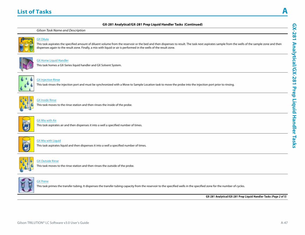
Gilson TRILUTION® LC Software v3.0 User’s Guide A-47
List of Tasks AG
X-281A
nalytical/GX-281 Prep Liquid H
andler Tasks
GX Dilute
This task aspirates the specified amount of diluent volume from the reservoir or the bed and then dispenses to result. The task next aspirates sample from the wells of the sample zone and then dispenses again to the result zone. Finally, a mix with liquid or air is performed in the wells of the result zone.
GX Home Liquid Handler
This task homes a GX-Series liquid handler and GX Solvent System.
GX Injection Rinse
This task rinses the injection port and must be synchronized with a Move to Sample Location task to move the probe into the injection port prior to rinsing.
GX Inside Rinse
This task moves to the rinse station and then rinses the inside of the probe.
GX Mix with Air
This task aspirates air and then dispenses it into a well a specified number of times.
GX Mix with Liquid
This task aspirates liquid and then dispenses it into a well a specified number of times.
GX Outside Rinse
This task moves to the rinse station and then rinses the outside of the probe.
GX Prime
This task primes the transfer tubing. It dispenses the transfer tubing capacity from the reservoir to the specified wells in the specified zone for the number of cycles.
GX-281 Analytical/GX-281 Prep Liquid Handler Tasks (Continued)
Gilson Task Name and Description
GX-281 Analytical/GX-281 Prep Liquid Handler Tasks (Page 2 of 5)
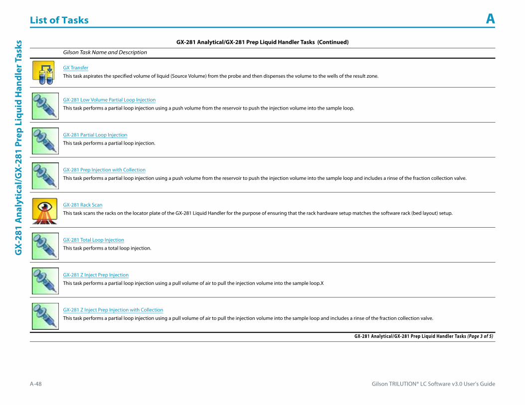
List of Tasks A
A-48 Gilson TRILUTION® LC Software v3.0 User’s Guide
GX-
281
Ana
lyti
cal/G
X-28
1 Pr
ep L
iqui
d H
andl
er T
asks
GX Transfer
This task aspirates the specified volume of liquid (Source Volume) from the probe and then dispenses the volume to the wells of the result zone.
GX-281 Low Volume Partial Loop Injection
This task performs a partial loop injection using a push volume from the reservoir to push the injection volume into the sample loop.
GX-281 Partial Loop Injection
This task performs a partial loop injection.
GX-281 Prep Injection with Collection
This task performs a partial loop injection using a push volume from the reservoir to push the injection volume into the sample loop and includes a rinse of the fraction collection valve.
GX-281 Rack Scan
This task scans the racks on the locator plate of the GX-281 Liquid Handler for the purpose of ensuring that the rack hardware setup matches the software rack (bed layout) setup.
GX-281 Total Loop Injection
This task performs a total loop injection.
GX-281 Z Inject Prep Injection
This task performs a partial loop injection using a pull volume of air to pull the injection volume into the sample loop.X
GX-281 Z Inject Prep Injection with Collection
This task performs a partial loop injection using a pull volume of air to pull the injection volume into the sample loop and includes a rinse of the fraction collection valve.
GX-281 Analytical/GX-281 Prep Liquid Handler Tasks (Continued)
Gilson Task Name and Description
GX-281 Analytical/GX-281 Prep Liquid Handler Tasks (Page 3 of 5)

Gilson TRILUTION® LC Software v3.0 User’s Guide A-49
List of Tasks AG
X-281A
nalytical/GX-281 Prep Liquid H
andler Tasks
Injection Valve Position
This task sets the injection valve position on the Injector to either LOAD or INJECT.
Move to Sample Location
This task moves the probe to a specified height in a specified well in a specified zone.
Set Fraction Site
This task identifies where fraction collection will begin for an injected sample.
Set Multiple Bed Collection
This task is used to set the fraction site when multiple fraction collectors are being used.
Set Non Peak Per Tube
This task sets parameters for collecting non-peaks.
Set Peak Level
This task sets the parameters for fraction collection by level.
Set Peak Per Tube
This task sets parameters for collecting peaks.
Set Peak Slope
This task sets the parameters for fraction collection by slope.
GX-281 Analytical/GX-281 Prep Liquid Handler Tasks (Continued)
Gilson Task Name and Description
GX-281 Analytical/GX-281 Prep Liquid Handler Tasks (Page 4 of 5)

List of Tasks A
A-50 Gilson TRILUTION® LC Software v3.0 User’s Guide
GX-
281
Ana
lyti
cal/G
X-28
1 Pr
ep L
iqui
d H
andl
er T
asks
Start Fraction Collection
This task tells TRILUTION LC to begin collecting fractions. This task has no properties to set.
Stop Fraction Collection
This task tells TRILUTION LC to stop collecting fractions. This task has no properties to set.
Voltage On - Off
This task opens and powers off or closes and powers on a specified contact on a specified liquid handler.
Wait for Contact
This task initiates a wait in the method until any contact state change or a user-specified contact state change for the specified contact is detected. Sync to the end of the task (using a Sync task) to prevent other tasks in the method from executing during the wait.
Write to Display
This task displays a message in the front panel display of the selected instrument.
GX-281 Analytical/GX-281 Prep Liquid Handler Tasks (Continued)
Gilson Task Name and Description
GX-281 Analytical/GX-281 Prep Liquid Handler Tasks (Page 5 of 5)
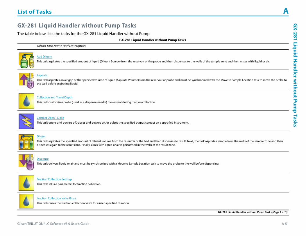
Gilson TRILUTION® LC Software v3.0 User’s Guide A-51
List of Tasks AG
X-281 Liquid Handler w
ithout Pump Tasks
GX-281 Liquid Handler without Pump TasksThe table below lists the tasks for the GX-281 Liquid Handler without Pump.
GX-281 Liquid Handler without Pump Tasks
Gilson Task Name and Description
Add Diluent
This task aspirates the specified amount of liquid (Diluent Source) from the reservoir or the probe and then dispenses to the wells of the sample zone and then mixes with liquid or air.
Aspirate
This task aspirates an air gap or the specified volume of liquid (Aspirate Volume) from the reservoir or probe and must be synchronized with the Move to Sample Location task to move the probe to the well before aspirating liquid.
Collection and Travel Depth
This task customizes probe (used as a dispense needle) movement during fraction collection.
Contact Open - Close
This task opens and powers off, closes and powers on, or pulses the specified output contact on a specified instrument.
Dilute
This task aspirates the specified amount of diluent volume from the reservoir or the bed and then dispenses to result. Next, the task aspirates sample from the wells of the sample zone and then dispenses again to the result zone. Finally, a mix with liquid or air is performed in the wells of the result zone.
Dispense
This task delivers liquid or air and must be synchronized with a Move to Sample Location task to move the probe to the well before dispensing.
Fraction Collection Settings
This task sets all parameters for fraction collection.
Fraction Collection Valve Rinse
This task rinses the fraction collection valve for a user-specified duration.
GX-281 Liquid Handler without Pump Tasks (Page 1 of 5)
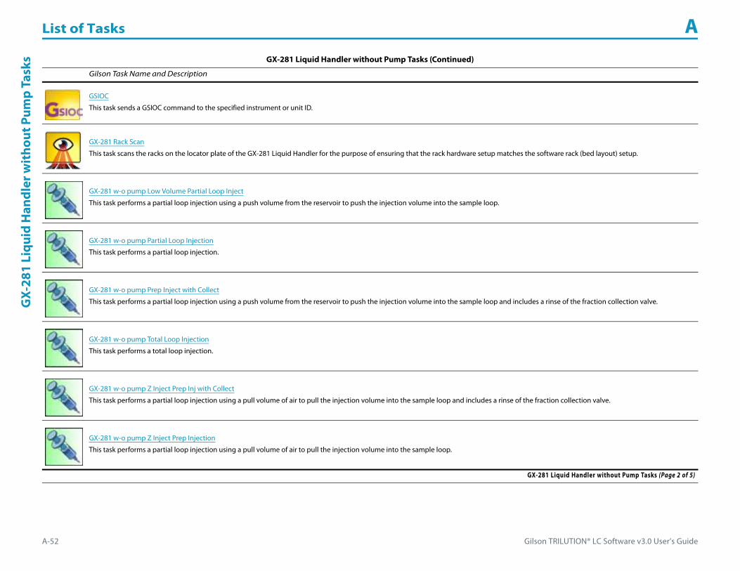
List of Tasks A
A-52 Gilson TRILUTION® LC Software v3.0 User’s Guide
GX-
281
Liqu
id H
andl
er w
itho
ut P
ump
Task
s
GSIOC
This task sends a GSIOC command to the specified instrument or unit ID.
GX-281 Rack Scan
This task scans the racks on the locator plate of the GX-281 Liquid Handler for the purpose of ensuring that the rack hardware setup matches the software rack (bed layout) setup.
GX-281 w-o pump Low Volume Partial Loop Inject
This task performs a partial loop injection using a push volume from the reservoir to push the injection volume into the sample loop.
GX-281 w-o pump Partial Loop Injection
This task performs a partial loop injection.
GX-281 w-o pump Prep Inject with Collect
This task performs a partial loop injection using a push volume from the reservoir to push the injection volume into the sample loop and includes a rinse of the fraction collection valve.
GX-281 w-o pump Total Loop Injection
This task performs a total loop injection.
GX-281 w-o pump Z Inject Prep Inj with Collect
This task performs a partial loop injection using a pull volume of air to pull the injection volume into the sample loop and includes a rinse of the fraction collection valve.
GX-281 w-o pump Z Inject Prep Injection
This task performs a partial loop injection using a pull volume of air to pull the injection volume into the sample loop.
GX-281 Liquid Handler without Pump Tasks (Continued)
Gilson Task Name and Description
GX-281 Liquid Handler without Pump Tasks (Page 2 of 5)

Gilson TRILUTION® LC Software v3.0 User’s Guide A-53
List of Tasks AG
X-281 Liquid Handler w
ithout Pump Tasks
Home Liquid Handler
This task homes the specified liquid handler.
Injection Rinse
This task rinses the injection port and must be synchronized with a Move to Sample Location task to move the probe to the injection port prior to rinsing.
Injection Valve Position
This task sets the injection valve position on the Injector to either LOAD or INJECT.
Inside Rinse
This task moves to the rinse station and then rinses the inside of the probe.
Mix with Air
This task aspirates air and then dispenses it into a well a specified number of times.
Mix with Liquid
This task aspirates liquid and then dispenses it into a well a specified number of times.
Move to Sample Location
This task moves the probe to a specified height in a specified well in a specified zone.
Outside Rinse
This task moves to the rinse station and then rinses the outside of the probe.
GX-281 Liquid Handler without Pump Tasks (Continued)
Gilson Task Name and Description
GX-281 Liquid Handler without Pump Tasks (Page 3 of 5)

List of Tasks A
A-54 Gilson TRILUTION® LC Software v3.0 User’s Guide
GX-
281
Liqu
id H
andl
er w
itho
ut P
ump
Task
s
Prime Dilutor
This task primes the dilutor. It aspirates the syringe capacity from the reservoir and then dispenses to the specified wells in the specified zone for the number of cycles.
Set Fraction Site
This task identifies where fraction collection will begin for an injected sample.
Set Multiple Bed Collection
This task is used to set the fraction site when multiple fraction collectors are being used.
Set Non Peak Per Tube
This task sets parameters for collecting non-peaks.
Set Peak Level
This task sets the parameters for fraction collection by level.
Set Peak Per Tube
This task sets parameters for collecting peaks.
Set Peak Slope
This task sets the parameters for fraction collection by slope.
Start Fraction Collection
This task tells TRILUTION LC to begin collecting fractions. This task has no properties to set.
GX-281 Liquid Handler without Pump Tasks (Continued)
Gilson Task Name and Description
GX-281 Liquid Handler without Pump Tasks (Page 4 of 5)

Gilson TRILUTION® LC Software v3.0 User’s Guide A-55
List of Tasks AG
X-281 Liquid Handler w
ithout Pump Tasks
Stop Fraction Collection
This task tells TRILUTION LC to stop collecting fractions. This task has no properties to set.
Transfer
This task aspirates the specified volume of liquid (Source Volume) from the probe and then dispenses the volume to the wells of the result zone.
Voltage On - Off
This task opens and powers off or closes and powers on a specified contact on a specified liquid handler.
Wait for Contact
This task initiates a wait in the method until any contact state change or a user-specified contact state change for the specified contact is detected. Sync to the end of the task (using a Sync task) to prevent other tasks in the method from executing during the wait.
Write to Display
This task displays a message in the front panel display of the selected instrument.
GX-281 Liquid Handler without Pump Tasks (Continued)
Gilson Task Name and Description
GX-281 Liquid Handler without Pump Tasks (Page 5 of 5)
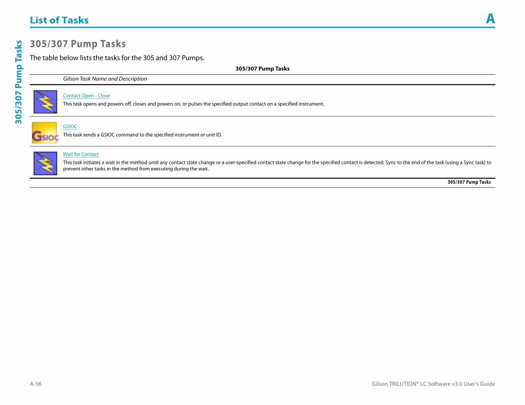
List of Tasks A
A-56 Gilson TRILUTION® LC Software v3.0 User’s Guide
305/
307
Pum
p Ta
sks 305/307 Pump Tasks
The table below lists the tasks for the 305 and 307 Pumps.305/307 Pump Tasks
Gilson Task Name and Description
Contact Open - Close
This task opens and powers off, closes and powers on, or pulses the specified output contact on a specified instrument.
GSIOC
This task sends a GSIOC command to the specified instrument or unit ID.
Wait for Contact
This task initiates a wait in the method until any contact state change or a user-specified contact state change for the specified contact is detected. Sync to the end of the task (using a Sync task) to prevent other tasks in the method from executing during the wait.
305/307 Pump Tasks

Gilson TRILUTION® LC Software v3.0 User’s Guide A-57
List of Tasks A306 Pum
p Tasks
306 Pump TasksThe table below lists the task for the 306 Pump.
306 Pump Tasks
Gilson Task Name and Description
GSIOC
This task sends a GSIOC command to the specified instrument or unit ID.
306 Pump Tasks
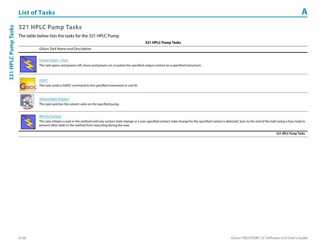
List of Tasks A
A-58 Gilson TRILUTION® LC Software v3.0 User’s Guide
321
HPL
C Pu
mp
Task
s 321 HPLC Pump TasksThe table below lists the tasks for the 321 HPLC Pump.
321 HPLC Pump Tasks
Gilson Task Name and Description
Contact Open - Close
This task opens and powers off, closes and powers on, or pulses the specified output contact on a specified instrument.
GSIOC
This task sends a GSIOC command to the specified instrument or unit ID.
Solvent Valve Position
This task switches the solvent valve on the specified pump.
Wait for Contact
This task initiates a wait in the method until any contact state change or a user-specified contact state change for the specified contact is detected. Sync to the end of the task (using a Sync task) to prevent other tasks in the method from executing during the wait.
321 HPLC Pump Tasks

Gilson TRILUTION® LC Software v3.0 User’s Guide A-59
List of Tasks A322 H
PLC Pump Tasks
322 HPLC Pump TasksThe table below lists the tasks for the 322 HPLC Pump.
322 HPLC Pump Tasks
Gilson Task Name and Description
GSIOC
This task sends a GSIOC command to the specified instrument or unit ID.
Solvent Valve Position
This task switches the solvent valve on the specified pump.
322 HPLC Pump Tasks
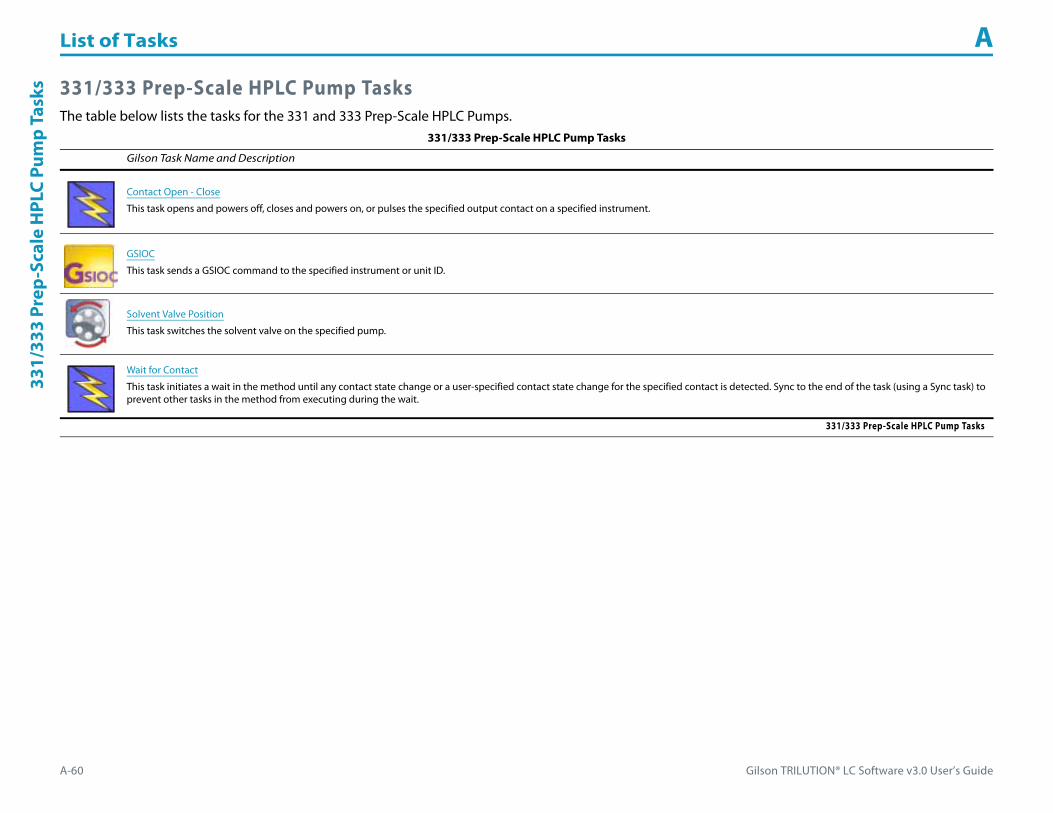
List of Tasks A
A-60 Gilson TRILUTION® LC Software v3.0 User’s Guide
331/
333
Prep
-Sca
le H
PLC
Pum
p Ta
sks 331/333 Prep-Scale HPLC Pump Tasks
The table below lists the tasks for the 331 and 333 Prep-Scale HPLC Pumps.331/333 Prep-Scale HPLC Pump Tasks
Gilson Task Name and Description
Contact Open - Close
This task opens and powers off, closes and powers on, or pulses the specified output contact on a specified instrument.
GSIOC
This task sends a GSIOC command to the specified instrument or unit ID.
Solvent Valve Position
This task switches the solvent valve on the specified pump.
Wait for Contact
This task initiates a wait in the method until any contact state change or a user-specified contact state change for the specified contact is detected. Sync to the end of the task (using a Sync task) to prevent other tasks in the method from executing during the wait.
331/333 Prep-Scale HPLC Pump Tasks
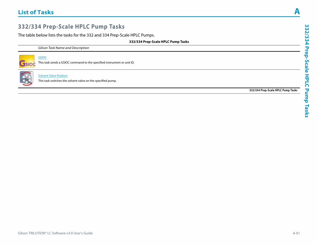
Gilson TRILUTION® LC Software v3.0 User’s Guide A-61
List of Tasks A332/334 Prep-Scale H
PLC Pump Tasks
332/334 Prep-Scale HPLC Pump TasksThe table below lists the tasks for the 332 and 334 Prep-Scale HPLC Pumps.
332/334 Prep-Scale HPLC Pump Tasks
Gilson Task Name and Description
GSIOC
This task sends a GSIOC command to the specified instrument or unit ID.
Solvent Valve Position
This task switches the solvent valve on the specified pump.
332/334 Prep-Scale HPLC Pump Tasks

List of Tasks A
A-62 Gilson TRILUTION® LC Software v3.0 User’s Guide
VALV
EMAT
E®/V
ALV
EMAT
E® II
Tas
ks VALVEMATE®/VALVEMATE® II TasksThe table below lists the tasks for the VALVEMATE and VALVEMATE II.
VALVEMATE®/VALVEMATE® II Tasks
Gilson Task Name and Description
GSIOC
This task sends a GSIOC command to the specified instrument or unit ID.
Switch VALVEMATE
This task changes the valve position on a VALVEMATE or VALVEMATE II.
VALVEMATE®/VALVEMATE® II Tasks
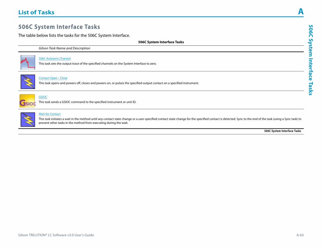
Gilson TRILUTION® LC Software v3.0 User’s Guide A-63
List of Tasks A506C System
Interface Tasks
506C System Interface TasksThe table below lists the tasks for the 506C System Interface.
506C System Interface Tasks
Gilson Task Name and Description
506C Autozero Channel
This task sets the output trace of the specified channels on the System Interface to zero.
Contact Open - Close
This task opens and powers off, closes and powers on, or pulses the specified output contact on a specified instrument.
GSIOC
This task sends a GSIOC command to the specified instrument or unit ID.
Wait for Contact
This task initiates a wait in the method until any contact state change or a user-specified contact state change for the specified contact is detected. Sync to the end of the task (using a Sync task) to prevent other tasks in the method from executing during the wait.
506C System Interface Tasks

List of Tasks A
A-64 Gilson TRILUTION® LC Software v3.0 User’s Guide
606
GSI
OC
to R
S-23
2 Co
nver
ter T
asks 606 GSIOC to RS-232 Converter Tasks
The table below lists the task for the 606 GSIOC to RS-232 Converter.606 GSIOC to RS-232 Converter Tasks
Gilson Task Name and Description
GSIOC
This task sends a GSIOC command to the specified instrument or unit ID.
606 GSIOC to RS-232 Converter Tasks
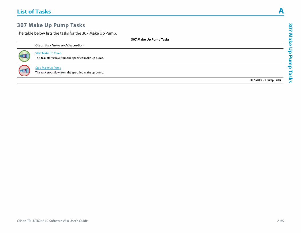
Gilson TRILUTION® LC Software v3.0 User’s Guide A-65
List of Tasks A307 M
ake Up Pum
p Tasks
307 Make Up Pump TasksThe table below lists the tasks for the 307 Make Up Pump.
307 Make Up Pump Tasks
Gilson Task Name and Description
Start Make Up Pump
This task starts flow from the specified make up pump.
Stop Make Up Pump
This task stops flow from the specified make up pump.
307 Make Up Pump Tasks
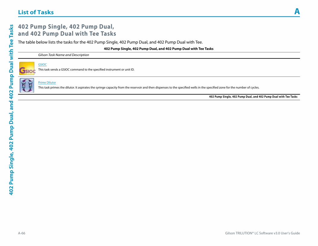
List of Tasks A
A-66 Gilson TRILUTION® LC Software v3.0 User’s Guide
402
Pum
p Si
ngle
, 402
Pum
p D
ual,
and
402
Pum
p D
ual w
ith
Tee
Task
s 402 Pump Single, 402 Pump Dual, and 402 Pump Dual with Tee TasksThe table below lists the tasks for the 402 Pump Single, 402 Pump Dual, and 402 Pump Dual with Tee.
402 Pump Single, 402 Pump Dual, and 402 Pump Dual with Tee Tasks
Gilson Task Name and Description
GSIOC
This task sends a GSIOC command to the specified instrument or unit ID.
Prime Dilutor
This task primes the dilutor. It aspirates the syringe capacity from the reservoir and then dispenses to the specified wells in the specified zone for the number of cycles.
402 Pump Single, 402 Pump Dual, and 402 Pump Dual with Tee Tasks

Gilson TRILUTION® LC Software v3.0 User’s Guide A-67
List of Tasks AVirtual Pum
ping System Tasks
Virtual Pumping System TasksThe table below lists the tasks for the Virtual Pumping System.
Virtual Pumping System Tasks
Gilson Task Name and Description
GSIOC
This task sends a GSIOC command to the specified instrument or unit ID.
Prime Dilutor
This task primes the dilutor. It aspirates the syringe capacity from the reservoir and then dispenses to the specified wells in the specified zone for the number of cycles.
Virtual Pumping System Tasks
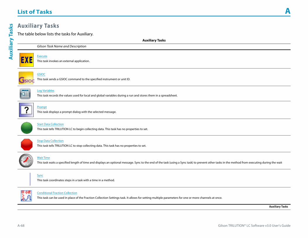
List of Tasks A
A-68 Gilson TRILUTION® LC Software v3.0 User’s Guide
Aux
iliar
y Ta
sks Auxiliary Tasks
The table below lists the tasks for Auxiliary.Auxiliary Tasks
Gilson Task Name and Description
Execute
This task invokes an external application.
GSIOC
This task sends a GSIOC command to the specified instrument or unit ID.
Log Variables
This task records the values used for local and global variables during a run and stores them in a spreadsheet.
Prompt
This task displays a prompt dialog with the selected message.
Start Data Collection
This task tells TRILUTION LC to begin collecting data. This task has no properties to set.
Stop Data Collection
This task tells TRILUTION LC to stop collecting data. This task has no properties to set.
Wait Time
This task waits a specified length of time and displays an optional message. Sync to the end of the task (using a Sync task) to prevent other tasks in the method from executing during the wait
Sync
This task coordinates steps in a task with a time in a method.
Conditional Fraction Collection
This task can be used in place of the Fraction Collection Settings task. It allows for setting multiple parameters for one or more channels at once.
Auxiliary Tasks

Gilson TRILUTION® LC Software v3.0 User’s Guide A-69
List of Tasks AM
obile Phase Tasks
Mobile Phase TasksThe table below lists the mobile phase tasks.
Mobile Phase Tasks
Gilson Task Name and Description
Gradient Task
This task adds a gradient point to a template in the control workspace.
Gradient Task with Variables
This task adds a gradient with variables mobile phase to the control.
Isocratic
This task adds an isocratic mobile phase template to the control.
Linear Gradient with Column Wash Out
This task adds a linear gradient with column wash out mobile phase template to the control.
Linear Gradient with No Column Wash Out
This task adds a linear gradient with no column wash out mobile phase template to the control.
Multi Linear Gradient with Step and Column Wash Out
This task adds a multi linear gradient with step and column wash out mobile phase template to the control.
Multi Linear Gradient with Column Wash Out
This task adds a multiple linear gradient with column wash out mobile phase template to the control.
Mobile Phase Tasks

List of Tasks A
A-70 Gilson TRILUTION® LC Software v3.0 User’s Guide
Gra
dien
t Tas
k Gradient TaskThis task adds a gradient point to a template in the control workspace.
Use the following steps to add this task to the control:
1 Ensure that you have mobile phase pumps in the configuration.2 Drag the Gradient Task and drop it in the workspace.3 In the Flow Rate field, type the desired total flow rate.
For more information, refer to Add a Point to the Mobile Phase Template on page 6-13.
Gradient Task with VariablesThis task adds a gradient with variables mobile phase to the control.
How to Use the Gradient Task with Variables1 Ensure that there are mobile phase pumps in the configuration.2 Drag the Gradient Task with Variables and drop it in the workspace.3 In the Flow Rate field, type the desired total flow rate or a variable. 4 In the Time field, type the time at which the pumps will begin pumping at the specified flow rate and composition conditions or a variable.5 In the Concentration % column, type the percent composition for the first pump or a variable. The software calculates the percent composition for
additional pumps..
A variable is created by typing # and then the variable name. The variable value is satisfied in the sample list. For more information, refer to Create a New Variable (Method Builder) on page 13-2.

Gilson TRILUTION® LC Software v3.0 User’s Guide A-71
List of Tasks AIsocratic
IsocraticTo add an isocratic mobile phase template to the control:
1 Ensure that you have mobile phase pumps in the configuration.2 Drag the Isocratic template and drop it in the workspace.3 Specify the flow rate or a variable. A variable is created by typing # and then the variable name. The variable value is satisfied in the sample list. For more
information, refer to Create a New Variable (Method Builder) on page 13-2.
For more information, refer to How to Create Gradient or Isocratic Conditions on page 6-13.
Linear Gradient with Column Wash OutTo add a linear gradient with column wash out mobile phase template to the control:
1 Ensure that you have mobile phase pumps in the configuration.2 Drag the Linear Gradient with Column Wash Out template and drop it in the workspace.3 Specify the flow rate or a variable. A variable is created by typing # and then the variable name. The variable value is satisfied in the sample list. For more
information, refer to Create a New Variable (Method Builder) on page 13-2.
For more information, refer to How to Create Gradient or Isocratic Conditions on page 6-13.
Linear Gradient with No Column Wash OutTo add a linear gradient with no column wash out mobile phase template to the control:
1 Ensure that you have mobile phase pumps in the configuration.2 Drag the Linear Gradient with No Column Wash Out template and drop it in the workspace.3 Specify the flow rate or a variable. A variable is created by typing # and then the variable name. The variable value is satisfied in the sample list. For more
information, refer to Create a New Variable (Method Builder) on page 13-2.
For more information, refer to How to Create Gradient or Isocratic Conditions on page 6-13.

List of Tasks A
A-72 Gilson TRILUTION® LC Software v3.0 User’s Guide
Mul
ti L
inea
r Gra
dien
t wit
h St
ep a
nd C
olum
n W
ash
Out Multi Linear Gradient
with Step and Column Wash OutTo add a multi linear gradient with step and column wash out mobile phase template to the control:
1 Ensure that you have mobile phase pumps in the configuration.2 Drag the Multi Linear Gradient with Step and Column Wash Out template and drop it in the workspace.3 Specify the flow rate or a variable. A variable is created by typing # and then the variable name. The variable value is satisfied in the sample list. For more
information, refer to Create a New Variable (Method Builder) on page 13-2.
For more information, refer to How to Create Gradient or Isocratic Conditions on page 6-13.
Multi Linear Gradient with Column Wash OutTo add a multi linear gradient with column wash out mobile phase template to the control:
1 Ensure that you have mobile phase pumps in the configuration.2 Drag the Multi Linear Gradient with Column Wash Out template and drop it in the workspace.3 Specify the flow rate or a variable. A variable is created by typing # and then the variable name. The variable value is satisfied in the sample list. For more
information, refer to Create a New Variable (Method Builder) on page 13-2.
For more information, refer to How to Create Gradient or Isocratic Conditions on page 6-13.

Gilson TRILUTION® LC Software v3.0 User’s Guide A-73
List of Tasks AA
ll Tasks(in alphabetical order)
All Tasks (in alphabetical order)Gilson Task Name
151 152 Detector Settings 155 156 Detector Settings 155 156 Scan Initiation 171 172 Detector Settings 215 819 Low Volume Partial Loop Injection
215 819 Partial Loop Injection 215 819 Prep Injection with Collection 233 XL Prep Injection with Collection 234 Partial Loop Injection 234 Total Loop Injection
235S Partial Loop Injection 235S Total Loop Injection 235T Injection Rinse 235T Partial Loop Injection 235T Total Loop Injection
506C Autozero Channel 845Z Prep Injection 845Z Prep Injection with Collection Add Diluent Aspirate
Collection and Travel Depth Conditional Fraction Collection Contact Open - Close Detector Autozero Channel Dilute
Dispense Execute Fraction Collection Settings Fraction Collection Valve Rinse GSIOC
GX Add Diluent GX Dilute GX Home Liquid Handler GX Injection Rinse GX Inside Rinse
GX Mix with Air GX Mix with Liquid GX Outside Rinse GX Prime GX Transfer
GX-271 Low Volume Partial Loop Injection GX-271 Partial Loop Injection GX-271 Prep Injection with Collection GX-271 Prep Injection with Collection
High Mount GX-271 Total Loop Injection
GX-271 Total Loop Injection Overfill GX-281 Low Volume Partial Loop Injection GX-281 Partial Loop Injection GX-281 Prep Injection with Collection GX-281 Rack Scan
GX-281 Total Loop Injection GX-281 w-o pump Low Volume Partial Loop Inject GX-281 w-o pump Partial Loop Injection GX-281 w-o pump Prep Inject with
Collect GX-281 w-o pump Total Loop Injection
GX-281 w-o pump Z Inject Prep Inj with Collect GX-281 w-o pump Z Inject Prep Injection GX-281 Z Inject Prep Injection GX-281 Z Inject Prep Injection with
CollectionHigh Mount Fraction Collection Valve Flush
Home Fraction Collector Home Liquid Handler Injection Rinse Injection Valve Position Inside Rinse
Log Variables Low Volume Partial Loop Injection Mass Spec Auto Tune Mass Spec Check Tune Mass Spec Single Quad APCI Settings
Mass Spec Single Quad Settings Mass Spec Single Quad Standby Mass Spec Single Quad Start Up Mix with Air Mix with Liquid
Move to Sample Location Outside Rinse Partial Loop Injection Prep Injection with Collection Prep Injection with Collection High Mount
Prime Dilutor Prompt Set Detector Mode Set Fraction Site Set Multiple Bed Collection
Set Non Peak Per Tube Set Peak Level Set Peak Per Tube Set Peak Slope Set Peak Width
Set Sensitivity Set Wavelength Solvent Valve Position Start Data Collection Stop Fraction Collection
Start Make Up Pump Start Data Collection Stop Fraction Collection Stop Make Up Pump Switch VALVEMATE
Sync Total Loop Injection Overfill Transfer Turn Lamp Off Turn Lamp On
Voltage On - Off Wait for Contact Wait Time Write to Display XL Low Volume Partial Loop Injection
XL Partial Loop Injection XL Total Loop Injection

List of Tasks A
A-74 Gilson TRILUTION® LC Software v3.0 User’s Guide
151
152
Det
ecto
r Set
ting
s 151 152 Detector SettingsThis task sets the peak width, wavelength, and sensitivities for the 151 or 152 UV/VIS Detector.
For more information about the properties on each tab, refer to:
151 152 Detector Settings Properties
151 152 Detector Settings Properties
Property Name Description Default Value
Detector The detector that the task will affect. Detector
Peak Width
The detector must know the width of the narrowest peak in the run. The detector uses this information to optimize the presentation of peaks and to minimize baseline noise.
To set the peak width accurately, run a chromatogram using the minimum peak width setting. Measure the width at half height of the narrowest peak.
Valid range is 0 and 4–99 seconds.
0 sec
Sensitivity 1 One of two sensitivities for monitoring a sample on separate output channels. Valid range is 0.001 to 2.0 AUFS. 0.01 AUFS
Sensitivity 2 One of two sensitivities for monitoring a sample on separate output channels. Valid range is 0.001 to 2.0 AUFS. 0.01 AUFS
Wavelength The monitor wavelength. Valid range is 190–700 nm. 254 nm
151 152 Detector Settings Properties

Gilson TRILUTION® LC Software v3.0 User’s Guide A-75
List of Tasks A155 156 D
etector Settings
155 156 Detector SettingsThis task sets the mode, peak width, sensitivities, and wavelengths for the 155 or 156 UV/VIS Detector.
For more information about the properties on each tab, refer to:
155 156 Detector Settings Properties
155 156 Detector Settings Properties
Property Name Description Default Value
Detector The detector that the task will affect. Detector
Detector Mode Select from Single Mode, Dual Mode, or Scan Mode. Dual Mode
Single ModePeak Width
The detector must know the width of the narrowest peak in your run. The detector uses this information to optimize the presentation of peaks and to minimize baseline noise.
To set the peak width accurately, run a chromatogram using the minimum peak width setting. Measure the width at half height of the narrowest peak.
Valid range is 0 and 4–99 seconds.
0 sec
Single ModeSensitivity 1
One of two sensitivities for monitoring a sample on separate output channels. Valid range is 0.001 to 2.0 AUFS. 0.01 AUFS
155 156 Detector Settings Properties (Page 1 of 2)

List of Tasks A
A-76 Gilson TRILUTION® LC Software v3.0 User’s Guide
155
156
Det
ecto
r Set
ting
s
Single ModeSensitivity 2
One of two sensitivities for monitoring a sample on separate output channels. Valid range is 0.001 to 2.0 AUFS. 0.01 AUFS
Single ModeWavelength 1
The monitor wavelength. Valid range is 190–700 nm. 254 nm
Dual ModePeak Width
The detector must know the width of the narrowest peak in your run. The detector uses this information to optimize the presentation of peaks and to minimize baseline noise.
To set the peak width accurately, run a chromatogram using the minimum peak width setting. Measure the width at half height of the narrowest peak.
Valid range is 4–99.
0 sec
Dual ModeSensitivity 1
One of two sensitivities for monitoring a sample on separate output channels. Valid range is 0.001 to 2.0 AUFS. 0.01 AUFS
Dual ModeSensitivity 2
One of two sensitivities for monitoring a sample on separate output channels. Valid range is 0.001 to 2.0 AUFS. 0.01 AUFS
Dual ModeWavelength 1
The monitor wavelength. Valid range is 190–700 nm. 254 nm
Dual ModeWavelength 2
The monitor wavelength for output channel 2. Valid range is 190–700 nm. 280 nm
Scan ModePeak Width
The detector must know the width of the narrowest peak in your run. The detector uses this information to optimize the presentation of peaks and to minimize baseline noise.
To set the peak width accurately, run a chromatogram using the minimum peak width setting. Measure the width at half height of the narrowest peak.
Valid range is 0 and 4–99 seconds.
0 sec
Scan ModeSensitivity 1
One of two sensitivities for monitoring a sample on separate output channels. Valid range is 0.001 to 2.0 AUFS. 0.01 AUFS
Scan ModeSensitivity 2
One of two sensitivities for monitoring a sample on separate output channels. Valid range is 0.001 to 2.0 AUFS. 0.01 AUFS
Scan ModeScan Sensitivity
The sensitivity for monitoring output channel 3. Valid range is 0.001–2.000 AUFS 0.01 AUFS
Scan ModeScan Wavelength 1
The monitor wavelength. Valid range is 190–700 nm. 254 nm
Scan ModeScan Start Wavelength
The first wavelength in the range that will be scanned. Valid range is 190–700 nm. 190 nm
Scan ModeScan End Wavelength
The last wavelength in the range that will be scanned. Valid range is 190–700 nm. 700 nm
155 156 Detector Settings Properties (Continued)
Property Name Description Default Value
155 156 Detector Settings Properties (Page 2 of 2)

Gilson TRILUTION® LC Software v3.0 User’s Guide A-77
List of Tasks A155 156 Scan Initiation
155 156 Scan InitiationThis task sets the 155 or 156 UV/VIS Detector for an automatic scan.
For more information about the properties on each tab, refer to:
155 156 Scan Initiation Properties
155 156 Scan Initiation Properties
Property Name Description Default Value
Detector The detector that the task will affect. Detector
Automatic Scan Initiation When automatic scan initiation is selected, the scan is not performed until the absorbance reading reaches the Initiation Threshold. Selected
Initiation Threshold The absorbance reading to trigger the Automatic Scan Initiation. 1
Scan Output Time The time it takes the chart recorder to trace a wavelength scan on strip chart paper (does not affect time to scan a peak). Valid range is 0.1–20 min. 0.2 min
155 156 Scan Initiation Properties

List of Tasks A
A-78 Gilson TRILUTION® LC Software v3.0 User’s Guide
171
172
Det
ecto
r Set
ting
s 171 172 Detector SettingsThis task sets the DAD wavelengths and bandwidths to be monitored based on each selected Channel for the selected Detector.
For more information about the properties on each tab, refer to:
171 172 Detector Settings Properties
171 172 Detector Settings Properties
Property Name Description Default Value
Detector The detector that the task will affect. Detector
Channel Select Channel number for which wavelength and bandwidth values will be set. Repeat for each channel to be used. (1–8) 1
Monitor Wavelength
The wavelength at which chromatogram data will be extracted and displayed on-screen during the run.
Range for 171 Diode Array Detector:
[Monitor Wavelength - (0.5 x Monitor Wavelength Bandwidth)] > 186 and [Monitor Wavelength + (0.5 x Monitor Wavelength Bandwidth)] < 723
Range for the 172 Diode Array Detector:
[Monitor Wavelength - (0.5 x Monitor Wavelength Bandwidth)] > 186 and [Monitor Wavelength + (0.5 x Monitor Wavelength Bandwidth)] < 612
254 nm
Monitor Wavelength BandwidthThe number of wavelengths that TRILUTION LC will use in the chromatogram calculation for the monitor wavelength. Optimizing the bandwidth improves the signal-to-noise ratio to obtain the optimum signal for peak detection. (Range 1–15 nm, range dependent on setting for Monitor Wavelength)
10 nm
171 172 Detector Settings Properties (Page 1 of 2)

Gilson TRILUTION® LC Software v3.0 User’s Guide A-79
List of Tasks A171 172 D
etector Settings
Reference Wavelength
The reference wavelength is used to correct for background noise and instabilities in the detector. Choose a wavelength that is close to the monitor wavelength and in a region of non-absorbance.
Range for the 171 Diode Array Detector:
[Reference Wavelength - (0.5 x Reference Wavelength Bandwidth)] > 186 and [Reference Wavelength + (0.5 x Reference Wavelength Bandwidth)] < 723
Range for the 172 Diode Array Detector:
[Reference Wavelength - (0.5 x Reference Wavelength Bandwidth)] > 186 and [Reference Wavelength + (0.5 x Reference Wavelength Bandwidth)] < 612
330 nm
Reference Wavelength BandwidthThe reference wavelength bandwidth sets the number of wavelengths that TRILUTION LC will use in the chromatogram calculation for the reference wavelength. Optimizing the bandwidth improves the signal-to-noise ratio to obtain the optimum signal for peak detection. (Range 1–50 nm, range dependent on setting for Reference Wavelength)
40 nm
171 172 Detector Settings Properties (Continued)
Property Name Description Default Value
171 172 Detector Settings Properties (Page 2 of 2)

List of Tasks A
A-80 Gilson TRILUTION® LC Software v3.0 User’s Guide
215
819
Low
Vol
ume
Part
ial L
oop
Inje
ctio
n 215 819 Low Volume Partial Loop InjectionThis task performs a partial loop injection using a push volume from the reservoir to push the injection volume into the sample loop.
For more information about the properties on each tab, refer to:
215 819 Low Volume Partial Loop Injection Properties - Main
215 819 Low Volume Partial Loop Injection Properties - Advanced
215 819 Low Volume Partial Loop Injection Properties - Rinsing
215 819 Low Volume Partial Loop Injection - Sequence of Steps
215 819 Low Volume Partial Loop Injection Properties - Main
Property Name Description Default Value
Liquid Handler The liquid handler that the task will affect. Liquid Handler
Pump The pump that the task will affect. Liquid Handler
Injector The injector or injection module that the task will affect. Injector
Sample Zone The zone from which the Injection Volume and Extra Volume are aspirated. Sample Zone
Sample Well Enter the well number in the Sample Zone. 0
Injection Zone The zone to which the Extra Volume, Injection Volume, and Push Volume are dispensed. Injection Zone
215 819 Low Volume Partial Loop Injection Properties - Main (Page 1 of 2)
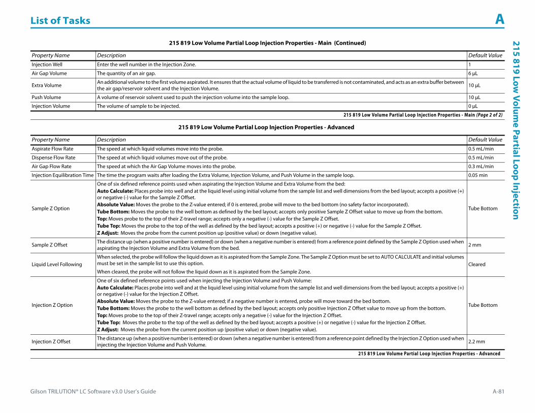
Gilson TRILUTION® LC Software v3.0 User’s Guide A-81
List of Tasks A215 819 Low
Volume Partial Loop Injection
Injection Well Enter the well number in the Injection Zone. 1
Air Gap Volume The quantity of an air gap. 6 μL
Extra Volume An additional volume to the first volume aspirated. It ensures that the actual volume of liquid to be transferred is not contaminated, and acts as an extra buffer between the air gap/reservoir solvent and the Injection Volume. 10 μL
Push Volume A volume of reservoir solvent used to push the injection volume into the sample loop. 10 μL
Injection Volume The volume of sample to be injected. 0 μL
215 819 Low Volume Partial Loop Injection Properties - Advanced
Property Name Description Default Value
Aspirate Flow Rate The speed at which liquid volumes move into the probe. 0.5 mL/min
Dispense Flow Rate The speed at which liquid volumes move out of the probe. 0.5 mL/min
Air Gap Flow Rate The speed at which the Air Gap Volume moves into the probe. 0.3 mL/min
Injection Equilibration Time The time the program waits after loading the Extra Volume, Injection Volume, and Push Volume in the sample loop. 0.05 min
Sample Z Option
One of six defined reference points used when aspirating the Injection Volume and Extra Volume from the bed:Auto Calculate: Places probe into well and at the liquid level using initial volume from the sample list and well dimensions from the bed layout; accepts a positive (+) or negative (-) value for the Sample Z Offset.Absolute Value: Moves the probe to the Z-value entered; if 0 is entered, probe will move to the bed bottom (no safety factor incorporated).Tube Bottom: Moves the probe to the well bottom as defined by the bed layout; accepts only positive Sample Z Offset value to move up from the bottom.Top: Moves probe to the top of their Z-travel range; accepts only a negative (-) value for the Sample Z Offset.Tube Top: Moves the probe to the top of the well as defined by the bed layout; accepts a positive (+) or negative (-) value for the Sample Z Offset.Z Adjust: Moves the probe from the current position up (positive value) or down (negative value).
Tube Bottom
Sample Z Offset The distance up (when a positive number is entered) or down (when a negative number is entered) from a reference point defined by the Sample Z Option used when aspirating the Injection Volume and Extra Volume from the bed. 2 mm
Liquid Level FollowingWhen selected, the probe will follow the liquid down as it is aspirated from the Sample Zone. The Sample Z Option must be set to AUTO CALCULATE and initial volumes must be set in the sample list to use this option.
When cleared, the probe will not follow the liquid down as it is aspirated from the Sample Zone.Cleared
Injection Z Option
One of six defined reference points used when injecting the Injection Volume and Push Volume:Auto Calculate: Places probe into well and at the liquid level using initial volume from the sample list and well dimensions from the bed layout; accepts a positive (+) or negative (-) value for the Injection Z Offset.Absolute Value: Moves the probe to the Z-value entered; if a negative number is entered, probe will move toward the bed bottom.Tube Bottom: Moves the probe to the well bottom as defined by the bed layout; accepts only positive Injection Z Offset value to move up from the bottom.Top: Moves probe to the top of their Z-travel range; accepts only a negative (-) value for the Injection Z Offset.Tube Top: Moves the probe to the top of the well as defined by the bed layout; accepts a positive (+) or negative (-) value for the Injection Z Offset.Z Adjust: Moves the probe from the current position up (positive value) or down (negative value).
Tube Bottom
Injection Z Offset The distance up (when a positive number is entered) or down (when a negative number is entered) from a reference point defined by the Injection Z Option used when injecting the Injection Volume and Push Volume. 2.2 mm
215 819 Low Volume Partial Loop Injection Properties - Advanced
215 819 Low Volume Partial Loop Injection Properties - Main (Continued)
Property Name Description Default Value
215 819 Low Volume Partial Loop Injection Properties - Main (Page 2 of 2)

List of Tasks A
A-82 Gilson TRILUTION® LC Software v3.0 User’s Guide
215
819
Low
Vol
ume
Part
ial L
oop
Inje
ctio
n
215 819 Low Volume Partial Loop Injection Properties - Rinsing For information about rinse positions, refer to Appendix B, Rinse Locations.
Property Name Description Default Value
Drain Zone The zone in which the dilutor is homed. Inside Rinse
Drain Well Enter the well number in the Drain Zone. 1
Drain Z Option
One of five defined reference points used when purging to the drain:Auto Calculate: Places probe into well and at the liquid level using initial volume from the sample list and well dimensions from the bed layout; accepts a positive (+) or negative (-) value for the Drain Z Offset.Absolute Value: Moves the probe to the Z-value entered; if 0 is entered for the Drain Z Offset, probe will move to the bed bottom (no safety factor incorporated).Tube Bottom: Moves the probe to the well bottom as defined by the bed layout; accepts only positive Drain Z Offset values to move up from the bottom.Top: Moves probe to the top of their Z-travel range; accepts only a negative (-) value for the Drain Z Offset.Tube Top: Moves the probe to the top of the well as defined by the bed layout; accepts a positive (+) or negative (-) value for the Drain Z Offset.
Tube Bottom
Drain Z Offset The distance up (when a positive number is entered) or down (when a negative number is entered) from a reference point defined by the Drain Z Option for purging to the drain. 2 mm
Injection Rinse Volume The quantity of liquid used to rinse the injection port at Injection Well in Injection Zone. 300 μL
Injection Rinse Flow Rate The speed at which the Injection Rinse Volume moves out of the probe and into the injection port. 4 mL/min
Outside Rinse Zone The zone to which the Outside Rinse Volume is delivered. Outside Rinse
Outside Rinse Well Enter the well number in the Outside Rinse Zone. 1
Outside Rinse Volume The quantity of liquid used to rinse the outside of the probe. 450 μL
Outside Rinse Flow Rate The speed at which the Outside Rinse Volume moves out of the probe and into the outside rinse position in the rinse station. 10 mL/min
Outside Rinse Z Option
One of five defined reference points used when performing the outside rinse:Auto Calculate: Places probe into well and at the liquid level using initial volume from the sample list and well dimensions from the bed layout; accepts a positive (+) or negative (-) value for the Outside Rinse Z Offset.Absolute Value: Moves the probe to the Z-value entered; if 0 is entered, probe will move to the bed bottom (no safety factor incorporated).Tube Bottom: Moves the probe to the well bottom as defined by the bed layout; accepts only positive Outside Rinse Z Offset values to move up from the bottom.Top: Moves probe to the top of their Z-travel range; accepts only a negative (-) value for the Outside Rinse Z Offset.Tube Top: Moves the probe to the top of the well as defined by the bed layout; accepts a positive (+) or negative (-) value for the Outside Rinse Z Offset.
Tube Bottom
Outside Rinse Z Offset The distance up (when a positive number is entered) or down (when a negative number is entered) from a reference point defined by the Outside Rinse Z Option for rinsing the probe at the outside rinse position in the rinse station. 2 mm
215 819 Low Volume Partial Loop Injection Properties - Rinsing

Gilson TRILUTION® LC Software v3.0 User’s Guide A-83
List of Tasks A215 819 Low
Volume Partial Loop Injection
215 819 Low Volume Partial Loop Injection - Sequence of StepsThe following is an overview for the sequence of steps.
1 Initialize2 Aspirate3 Inject4 Injection Port Rinse5 Outside Rinse
Initialize1 Move Z to Z Safe Height.2 Set injection valve to INJECT.3 Move to Drain Well in Drain Zone.4 Lower probe into well to Drain Z Option and Drain Z Offset.5 Home dilutor.6 Move Z to Z Safe Height.
Aspirate1 Aspirate Air Gap Volume at Air Gap Flow Rate.2 Aspirate Push Volume at Aspirate Flow Rate.3 Move to Sample Well in Sample Zone.4 Lower probe into well to Sample Z Option and Sample Z Offset.5 Aspirate Injection Volume + Extra Volume at Aspirate Flow Rate.6 Move Z to Z Safe Height.
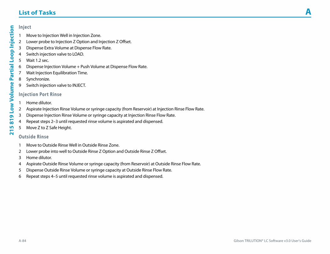
List of Tasks A
A-84 Gilson TRILUTION® LC Software v3.0 User’s Guide
215
819
Low
Vol
ume
Part
ial L
oop
Inje
ctio
n Inject1 Move to Injection Well in Injection Zone.2 Lower probe to Injection Z Option and Injection Z Offset.3 Dispense Extra Volume at Dispense Flow Rate.4 Switch injection valve to LOAD.5 Wait 1.2 sec.6 Dispense Injection Volume + Push Volume at Dispense Flow Rate.7 Wait Injection Equilibration Time.8 Synchronize.9 Switch injection valve to INJECT.
Injection Port Rinse1 Home dilutor.2 Aspirate Injection Rinse Volume or syringe capacity (from Reservoir) at Injection Rinse Flow Rate.3 Dispense Injection Rinse Volume or syringe capacity at Injection Rinse Flow Rate.4 Repeat steps 2–3 until requested rinse volume is aspirated and dispensed.5 Move Z to Z Safe Height.
Outside Rinse1 Move to Outside Rinse Well in Outside Rinse Zone.2 Lower probe into well to Outside Rinse Z Option and Outside Rinse Z Offset.3 Home dilutor.4 Aspirate Outside Rinse Volume or syringe capacity (from Reservoir) at Outside Rinse Flow Rate.5 Dispense Outside Rinse Volume or syringe capacity at Outside Rinse Flow Rate.6 Repeat steps 4–5 until requested rinse volume is aspirated and dispensed.
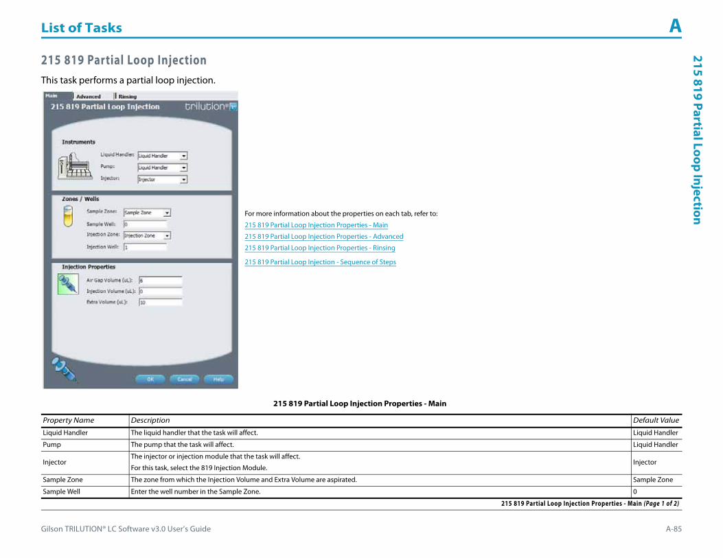
Gilson TRILUTION® LC Software v3.0 User’s Guide A-85
List of Tasks A215 819 Partial Loop Injection
215 819 Partial Loop InjectionThis task performs a partial loop injection.
For more information about the properties on each tab, refer to:
215 819 Partial Loop Injection Properties - Main
215 819 Partial Loop Injection Properties - Advanced
215 819 Partial Loop Injection Properties - Rinsing
215 819 Partial Loop Injection - Sequence of Steps
215 819 Partial Loop Injection Properties - Main
Property Name Description Default Value
Liquid Handler The liquid handler that the task will affect. Liquid Handler
Pump The pump that the task will affect. Liquid Handler
InjectorThe injector or injection module that the task will affect.
For this task, select the 819 Injection Module.Injector
Sample Zone The zone from which the Injection Volume and Extra Volume are aspirated. Sample Zone
Sample Well Enter the well number in the Sample Zone. 0
215 819 Partial Loop Injection Properties - Main (Page 1 of 2)

List of Tasks A
A-86 Gilson TRILUTION® LC Software v3.0 User’s Guide
215
819
Part
ial L
oop
Inje
ctio
n
Injection Zone The zone to which the Extra Volume, Injection Volume, and Push Volume are dispensed. Injection Zone
Injection Well Enter the well number in the Injection Zone. 1
Air Gap Volume The quantity of an air gap. 6 μL
Injection Volume The volume of sample to be injected. 0 μL
Extra Volume An additional volume to the first volume aspirated. It ensures that the actual volume of liquid to be transferred is not contaminated, and acts as an extra buffer between the air gap/reservoir solvent and the Injection Volume. 10 μL
215 819 Partial Loop Injection Properties - Advanced
Property Name Description Default Value
Aspirate Flow Rate The speed at which liquid volumes move into the probe. 0.5 mL/min
Dispense Flow Rate The speed at which liquid volumes move out of the probe. 0.5 mL/min
Air Gap Flow Rate The speed at which the Air Gap Volume moves into the probe. 0.3 mL/min
Injection Equilibration Time The time the program waits after loading the Extra Volume, Injection Volume, and Push Volume in the sample loop. 0.05 min
Sample Z Option
One of six defined reference points used when aspirating the Injection Volume and Extra Volume from the bed:Auto Calculate: Places probe into well and at the liquid level using initial volume from the sample list and well dimensions from the bed layout; accepts a positive (+) or negative (-) value for the Sample Z Offset.Absolute Value: Moves the probe to the Z-value entered; if 0 is entered, probe will move to the bed bottom (no safety factor incorporated).Tube Bottom: Moves the probe to the well bottom as defined by the bed layout; accepts only positive Sample Z Offset value to move up from the bottom.Top: Moves probe to the top of their Z-travel range; accepts only a negative (-) value for the Sample Z Offset.Tube Top: Moves the probe to the top of the well as defined by the bed layout; accepts a positive (+) or negative (-) value for the Sample Z Offset.Z Adjust: Moves the probe from the current position up (positive value) or down (negative value).
Tube Bottom
Sample Z Offset The distance up (when a positive number is entered) or down (when a negative number is entered) from a reference point defined by the Sample Z Option used when aspirating the Injection Volume and Extra Volume from the bed. 2 mm
Liquid Level FollowingWhen selected, the probe will follow the liquid down as it is aspirated from the Sample Zone. The Sample Z Option must be set to AUTO CALCULATE and initial volumes must be set in the sample list to use this option.
When cleared, the probe will not follow the liquid down as it is aspirated from the Sample Zone.Cleared
Injection Z Option
One of six defined reference points used when injecting the Injection Volume and Push Volume:Auto Calculate: Places probe into well and at the liquid level using initial volume from the sample list and well dimensions from the bed layout; accepts a positive (+) or negative (-) value for the Injection Z Offset.Absolute Value: Moves the probe to the Z-value entered; if a negative number is entered, probe will move toward the bed bottom.Tube Bottom: Moves the probe to the well bottom as defined by the bed layout; accepts only positive Injection Z Offset value to move up from the bottom.Top: Moves probe to the top of their Z-travel range; accepts only a negative (-) value for the Injection Z Offset.Tube Top: Moves the probe to the top of the well as defined by the bed layout; accepts a positive (+) or negative (-) value for the Injection Z Offset.Z Adjust: Moves the probe from the current position up (positive value) or down (negative value).
Tube Bottom
Injection Z Offset The distance up (when a positive number is entered) or down (when a negative number is entered) from a reference point defined by the Injection Z Option used when injecting the Injection Volume and Push Volume. 2.2 mm
215 819 Partial Loop Injection Properties - Advanced
215 819 Partial Loop Injection Properties - Main (Continued)
Property Name Description Default Value
215 819 Partial Loop Injection Properties - Main (Page 2 of 2)

Gilson TRILUTION® LC Software v3.0 User’s Guide A-87
List of Tasks A215 819 Partial Loop Injection
215 819 Partial Loop Injection Properties - Rinsing For information about rinse positions, refer to Appendix B, Rinse Locations.
Property Name Description Default Value
Drain Zone The zone in which the dilutor is homed. Inside Rinse
Drain Well Enter the well number in the Drain Zone. 1
Drain Z Option
One of six defined reference points used when purging to the drain:Auto Calculate: Places probe into well and at the liquid level using initial volume from the sample list and well dimensions from the bed layout; accepts a positive (+) or negative (-) value for the Drain Z Offset.Absolute Value: Moves the probe to the Z-value entered; if 0 is entered for the Drain Z Offset, probe will move to the bed bottom (no safety factor incorporated).Tube Bottom: Moves the probe to the well bottom as defined by the bed layout; accepts only positive Drain Z Offset values to move up from the bottom.Top: Moves probe to the top of their Z-travel range; accepts only a negative (-) value for the Drain Z Offset.Tube Top: Moves the probe to the top of the well as defined by the bed layout; accepts a positive (+) or negative (-) value for the Drain Z Offset.Z Adjust: Moves the probe from the current position up (positive value) or down (negative value).
Tube Bottom
Drain Z Offset The distance up (when a positive number is entered) or down (when a negative number is entered) from a reference point defined by the Drain Z Option for purging to the drain. 2 mm
Injection Rinse Volume The quantity of liquid used to rinse the injection port at Injection Well in Injection Zone. 300 μL
Injection Rinse Flow Rate The speed at which the Injection Rinse Volume moves out of the probe and into the injection port. 4 mL/min
Outside Rinse Zone The zone to which the Outside Rinse Volume is delivered. Outside Rinse
Outside Rinse Well Enter the well number in the Outside Rinse Zone. 1
Outside Rinse Volume The quantity of liquid used to rinse the outside of the probe. 450 μL
Outside Rinse Flow Rate The speed at which the Outside Rinse Volume moves out of the probe and into the outside rinse position in the rinse station. 10 mL/min
Outside Rinse Z Option
One of six defined reference points used when performing the outside rinse:Auto Calculate: Places probe into well and at the liquid level using initial volume from the sample list and well dimensions from the bed layout; accepts a positive (+) or negative (-) value for the Outside Rinse Z Offset.Absolute Value: Moves the probe to the Z-value entered; if 0 is entered, probe will move to the bed bottom (no safety factor incorporated).Tube Bottom: Moves the probe to the well bottom as defined by the bed layout; accepts only positive Outside Rinse Z Offset values to move up from the bottom.Top: Moves probe to the top of their Z-travel range; accepts only a negative (-) value for the Outside Rinse Z Offset.Tube Top: Moves the probe to the top of the well as defined by the bed layout; accepts a positive (+) or negative (-) value for the Outside Rinse Z Offset.Z Adjust: Moves the probe from the current position up (positive value) or down (negative value).
Tube Bottom
Outside Rinse Z Offset The distance up (when a positive number is entered) or down (when a negative number is entered) from a reference point defined by the Outside Rinse Z Option for rinsing the probe at the outside rinse position in the rinse station. 2 mm
215 819 Partial Loop Injection Properties - Rinsing

List of Tasks A
A-88 Gilson TRILUTION® LC Software v3.0 User’s Guide
215
819
Part
ial L
oop
Inje
ctio
n 215 819 Partial Loop Injection - Sequence of StepsThe following is an overview for the sequence of steps.
1 Initialize2 Aspirate3 Inject4 Injection Port Rinse5 Outside Rinse
Initialize1 Move Z to Z Safe Height.2 Set injection valve to INJECT.3 Move to Drain Well in Drain Zone.4 Lower probe into well to Drain Z Option and Drain Z Offset.5 Home dilutor.6 Move Z to Z Safe Height.
Aspirate1 Switch dilutor valve to probe and aspirate Air Gap Volume at Air Gap Flow Rate.2 Move to Sample Well in Sample Zone.3 Lower probe into well to Sample Z Option and Sample Z Offset.4 Switch dilutor valve to probe and aspirate Injection Volume + Extra Volume at Aspirate Flow Rate.5 Move Z to Z Safe Height.
Inject1 Move to Injection Well in Injection Zone.2 Lower probe to Injection Z Option and Injection Z Offset.3 Switch solvent valve to Solvent Valve Position and dispense Extra Volume at Dispense Flow Rate.4 Switch injection valve to LOAD.5 Wait 1.2 sec.6 Dispense Injection Volume at Dispense Flow Rate.7 Wait Injection Equilibration Time.8 Synchronize.9 Switch injection valve to INJECT.

Gilson TRILUTION® LC Software v3.0 User’s Guide A-89
List of Tasks A215 819 Partial Loop Injection
Injection Port Rinse1 Home dilutor.2 Switch dilutor valve to reservoir.3 Aspirate Injection Rinse Volume or syringe capacity at Injection Rinse Flow Rate.4 Switch dilutor valve to probe.5 Dispense Injection Rinse Volume or syringe capacity at Injection Rinse Flow Rate.6 Repeat steps 2–5 until requested rinse volume is aspirated and dispensed.7 Move Z to Z Safe Height.
Outside Rinse1 Move to Outside Rinse Well in Outside Rinse Zone.2 Lower probe into well to Outside Rinse Z Option and Outside Rinse Z Offset.3 Home dilutor.4 Switch dilutor valve to reservoir.5 Aspirate Outside Rinse Volume or syringe capacity at Outside Rinse Flow Rate.6 Switch dilutor valve to probe.7 Dispense Outside Rinse Volume or syringe capacity at Outside Rinse Flow Rate.8 Repeat steps 4–7 until requested rinse volume is aspirated and dispensed.

List of Tasks A
A-90 Gilson TRILUTION® LC Software v3.0 User’s Guide
215
819
Prep
Inje
ctio
n w
ith
Colle
ctio
n 215 819 Prep Injection with CollectionThis task is used when doing injection and fraction collection on the same bed. It performs a partial loop injection using a push volume from the reservoir to push the injection volume into the sample loop and includes a rinse of the fraction collection valve.
For more information about the properties on each tab, refer to:
215 819 Prep Injection with Collection Properties - Main
215 819 Prep Injection with Collection Properties - Advanced
215 819 Prep Injection with Collection Properties - Rinsing
215 819 Prep Injection with Collection - Sequence of Steps
215 819 Prep Injection with Collection Properties - Main
Property Name Description Default Value
Liquid Handler The liquid handler that the task will affect. Liquid Handler
Pump The pump that the task will affect. Liquid Handler
InjectorThe injector or injection module that the task will affect.
For this task, select the 819 Injection Module.Injector
215 819 Prep Injection with Collection Properties - Main (Page 1 of 2)

Gilson TRILUTION® LC Software v3.0 User’s Guide A-91
List of Tasks A215 819 Prep Injection w
ith Collection
Sample Zone The zone from which the Injection Volume is aspirated. Sample Zone
Sample Well Enter the well number in the Sample Zone. 0
Injection Zone The zone to which the Injection Volume, and Push Volume are dispensed. Injection Zone
Injection Well Enter the well number in the Injection Zone. 1
Air Gap Volume The quantity of an air gap. 6 μL
Push Volume A volume of reservoir solvent used to push the injection volume into the sample loop. 10 μL
Injection Volume The volume of sample to be injected. 0 μL
215 819 Prep Injection with Collection Properties - Advanced
Property Name Description Default Value
Aspirate Flow Rate The speed at which liquid volumes move into the probe. 3 mL/min
Dispense Flow Rate The speed at which liquid volumes move out of the probe. 3 mL/min
Air Gap Flow Rate The speed at which the Air Gap Volume moves into the probe. 0.3 mL/min
Injection Equilibration Time The time the program waits after loading the Extra Volume, Injection Volume, and Push Volume in the sample loop. 0.05 min
Sample Z Option
One of six defined reference points used when aspirating the Injection Volume and Extra Volume from the bed:Auto Calculate: Places probe into well and at the liquid level using initial volume from the sample list and well dimensions from the bed layout; accepts a positive (+) or negative (-) value for the Sample Z Offset.Absolute Value: Moves the probe to the Z-value entered; if 0 is entered, probe will move to the bed bottom (no safety factor incorporated).Tube Bottom: Moves the probe to the well bottom as defined by the bed layout; accepts only positive Sample Z Offset value to move up from the bottom.Top: Moves probe to the top of their Z-travel range; accepts only a negative (-) value for the Sample Z Offset.Tube Top: Moves the probe to the top of the well as defined by the bed layout; accepts a positive (+) or negative (-) value for the Sample Z Offset.Z Adjust: Moves the probe from the current position up (positive value) or down (negative value).
Tube Bottom
Sample Z Offset The distance up (when a positive number is entered) or down (when a negative number is entered) from a reference point defined by the Sample Z Option used when aspirating the Injection Volume and Extra Volume from the bed. 2 mm
Liquid Level FollowingWhen selected, the probe will follow the liquid down as it is aspirated from the Sample Zone. The Sample Z Option must be set to AUTO CALCULATE and initial volumes must be set in the sample list to use this option.
When cleared, the probe will not follow the liquid down as it is aspirated from the Sample Zone.Cleared
Injection Z Option
One of six defined reference points used when injecting the Injection Volume and Push Volume:Auto Calculate: Places probe into well and at the liquid level using initial volume from the sample list and well dimensions from the bed layout; accepts a positive (+) or negative (-) value for the Injection Z Offset.Absolute Value: Moves the probe to the Z-value entered; if a negative number is entered, probe will move toward the bed bottom.Tube Bottom: Moves the probe to the well bottom as defined by the bed layout; accepts only positive Injection Z Offset value to move up from the bottom.Top: Moves probe to the top of their Z-travel range; accepts only a negative (-) value for the Injection Z Offset.Tube Top: Moves the probe to the top of the well as defined by the bed layout; accepts a positive (+) or negative (-) value for the Injection Z Offset.Z Adjust: Moves the probe from the current position up (positive value) or down (negative value).
Tube Bottom
Injection Z Offset The distance up (when a positive number is entered) or down (when a negative number is entered) from a reference point defined by the Injection Z Option used when injecting the Injection Volume and Push Volume. 2.2 mm
215 819 Prep Injection with Collection Properties - Advanced
215 819 Prep Injection with Collection Properties - Main (Continued)
Property Name Description Default Value
215 819 Prep Injection with Collection Properties - Main (Page 2 of 2)

List of Tasks A
A-92 Gilson TRILUTION® LC Software v3.0 User’s Guide
215
819
Prep
Inje
ctio
n w
ith
Colle
ctio
n
215 819 Prep Injection with Collection Properties - Rinsing For information about rinse positions, refer to Appendix B, Rinse Locations.
Property Name Description Default Value
Drain Zone The zone in which the dilutor is homed. Inside Rinse
Drain Well Enter the well number in the Drain Zone. 1
Drain Z Option
One of six defined reference points used when purging to the drain:Auto Calculate: Places probe into well and at the liquid level using initial volume from the sample list and well dimensions from the bed layout; accepts a positive (+) or negative (-) value for the Drain Z Offset.Absolute Value: Moves the probe to the Z-value entered; if 0 is entered for the Drain Z Offset, probe will move to the bed bottom (no safety factor incorporated).Tube Bottom: Moves the probe to the well bottom as defined by the bed layout; accepts only positive Drain Z Offset values to move up from the bottom.Top: Moves probe to the top of their Z-travel range; accepts only a negative (-) value for the Drain Z Offset.Tube Top: Moves the probe to the top of the well as defined by the bed layout; accepts a positive (+) or negative (-) value for the Drain Z Offset.Z Adjust: Moves the probe from the current position up (positive value) or down (negative value).
Tube Bottom
Drain Z Offset The distance up (when a positive number is entered) or down (when a negative number is entered) from a reference point defined by the Drain Z Option for purging to the drain. 2 mm
Injection Rinse Volume The quantity of liquid used to rinse the injection port at Injection Well in Injection Zone. 300 μL
Injection Rinse Flow Rate The speed at which the Injection Rinse Volume moves out of the probe and into the injection port. 4 mL/min
Outside Rinse Zone The zone to which the Outside Rinse Volume is delivered. Outside Rinse
Outside Rinse Well Enter the well number in the Outside Rinse Zone. 1
Outside Rinse Volume The quantity of liquid used to rinse the outside of the probe. 450 μL
Outside Rinse Flow Rate The speed at which the Outside Rinse Volume moves out of the probe and into the outside rinse position in the rinse station. 10 mL/min
Outside Rinse Z Option
One of six defined reference points used when performing the outside rinse:Auto Calculate: Places probe into well and at the liquid level using initial volume from the sample list and well dimensions from the bed layout; accepts a positive (+) or negative (-) value for the Outside Rinse Z Offset.Absolute Value: Moves the probe to the Z-value entered; if 0 is entered, probe will move to the bed bottom (no safety factor incorporated).Tube Bottom: Moves the probe to the well bottom as defined by the bed layout; accepts only positive Outside Rinse Z Offset values to move up from the bottom.Top: Moves probe to the top of their Z-travel range; accepts only a negative (-) value for the Outside Rinse Z Offset.Tube Top: Moves the probe to the top of the well as defined by the bed layout; accepts a positive (+) or negative (-) value for the Outside Rinse Z Offset.Z Adjust: Moves the probe from the current position up (positive value) or down (negative value).
Tube Bottom
Outside Rinse Z Offset The distance up (when a positive number is entered) or down (when a negative number is entered) from a reference point defined by the Outside Rinse Z Option for rinsing the probe at the outside rinse position in the rinse station. 2 mm
215 819 Prep Injection with Collection Properties - Rinsing

Gilson TRILUTION® LC Software v3.0 User’s Guide A-93
List of Tasks A215 819 Prep Injection w
ith Collection
215 819 Prep Injection with Collection - Sequence of StepsThe following is an overview for the sequence of steps.
1 Initialize2 Aspirate3 Inject4 Injection Port Rinse5 Outside Rinse
Initialize1 Move Z to Z Safe Height.2 Set injection valve to INJECT.3 Move to Drain Well in Drain Zone.4 Lower probe into well to Drain Z Option and Drain Z Offset.5 Switch fraction collection valve to COLLECT for 2 seconds.6 Lower probe into drain well.7 Home dilutor.8 Move Z to Z Safe Height.
Aspirate1 Switch dilutor valve to probe and aspirate Air Gap Volume at Air Gap Flow Rate.2 Switch dilutor valve to reservoir and aspirate Push Volume at Aspirate Flow Rate.3 Move to Sample Well in Sample Zone.4 Lower probe into well to Sample Z Option and Sample Z Offset.5 Switch dilutor valve to probe and aspirate Injection Volume at Aspirate Flow Rate.6 Move Z to Z Safe Height.

List of Tasks A
A-94 Gilson TRILUTION® LC Software v3.0 User’s Guide
215
819
Prep
Inje
ctio
n w
ith
Colle
ctio
n Inject1 Move to Injection Well in Injection Zone.2 Lower probe into well to Injection Z Option and Injection Z Offset.3 Switch injection valve to LOAD.4 Wait 1.2 sec.5 Switch solvent valve to Solvent Valve Position and dispense Injection Volume + Push Volume at Dispense Flow Rate.6 Wait Injection Equilibration Time.7 Synchronize.8 Switch injection valve to INJECT.
Injection Port Rinse1 Home dilutor.2 Switch dilutor valve to reservoir.3 Aspirate Injection Rinse Volume or syringe capacity at Injection Rinse Flow Rate.4 Switch dilutor valve to probe.5 Dispense Injection Rinse Volume or syringe capacity at Injection Rinse Flow Rate.6 Repeat steps 2–5 until requested rinse volume is aspirated and dispensed.7 Move Z to Z Safe Height.
Outside Rinse1 Move to Outside Rinse Well in Outside Rinse Zone.2 Lower probe into well to Outside Rinse Z Option and Outside Rinse Z Offset.3 Home dilutor.4 Switch dilutor valve to reservoir.5 Aspirate Outside Rinse Volume or syringe capacity at Outside Rinse Flow Rate.6 Switch dilutor valve to probe.7 Dispense Outside Rinse Volume or syringe capacity at Outside Rinse Flow Rate.8 Repeat steps 4–7 until requested rinse volume is aspirated and dispensed.

Gilson TRILUTION® LC Software v3.0 User’s Guide A-95
List of Tasks A233 XL Prep Injection w
ith Collection
233 XL Prep Injection with CollectionThis task performs a partial loop injection using a push volume from the reservoir to push the injection volume into the sample loop and includes a rinse of the fraction collection valve.
For more information about the properties on each tab, refer to:
233 XL Prep Injection with Collection Properties - Main
233 XL Prep Injection with Collection Properties - Advanced
233 XL Prep Injection with Collection Properties - Rinsing
233 XL Prep Injection with Collection - Sequence of Steps
233 XL Prep Injection with Collection Properties - Main
Property Name Description Default Value
Sample Injector The sample injector that the task will affect. Liquid Handler
Pump The pump that the task will affect. Pump
Sample Zone The zone from which the Injection Volume is aspirated. Sample Zone
233 XL Prep Injection with Collection Properties - Main (Page 1 of 2)

List of Tasks A
A-96 Gilson TRILUTION® LC Software v3.0 User’s Guide
233
XL P
rep
Inje
ctio
n w
ith
Colle
ctio
n
Sample Well Enter the well number in the Sample Zone. 0
Injection Zone The zone to which the Injection Volume and Push Volume are dispensed. Injection Zone
Injection Well Enter the well number in the Injection Zone. 1
Air Gap Volume The quantity of an air gap. 6 μL
Push Volume A volume of reservoir solvent used to push the injection volume into the sample loop. 10 μL
Injection Volume The volume of sample to be injected. 0 μL
233 XL Prep Injection with Collection Properties - Advanced
Property Name Description Default Value
Aspirate Flow Rate The speed at which liquid volumes move into the probe. 2 mL/min
Dispense Flow Rate The speed at which liquid volumes move out of the probe. 2 mL/min
Air Gap Flow Rate The speed at which the Air Gap Volume moves into the probe. 0.5 mL/min
Injection Equilibration Time The time the program waits after loading the Injection Volume and Push Volume in the sample loop. 0.05 min
Sample Z Option
One of six defined reference points used when aspirating the Injection Volume and Extra Volume from the bed:Auto Calculate: Places probe into well and at the liquid level using initial volume from the sample list and well dimensions from the bed layout; accepts a positive (+) or negative (-) value for the Sample Z Offset.Absolute Value: Moves the probe to the Z-value entered; if a negative number is entered, probe will move toward the bed bottom.Tube Bottom: Moves the probe to the well bottom as defined by the bed layout; accepts only positive Sample Z Offset value to move up from the bottom.Top: Moves probe to the top of their Z-travel range; accepts only a negative (-) value for the Sample Z Offset.Tube Top: Moves the probe to the top of the well as defined by the bed layout; accepts a positive (+) or negative (-) value for the Sample Z Offset.Z Adjust: Moves the probe from the current position up (positive value) or down (negative value).
Tube Bottom
Sample Z Offset The distance up (when a positive number is entered) or down (when a negative number is entered) from a reference point defined by the Sample Z Option used when aspirating the Injection Volume from the bed. 2 mm
Liquid Level FollowingWhen selected, the probe will follow the liquid down as it is aspirated from the Sample Zone. The Sample Z Option must be set to AUTO CALCULATE and initial volumes must be set in the sample list to use this option.
When cleared, the probe will not follow the liquid down as it is aspirated from the Sample Zone.Cleared
Injection Z Option
One of six defined reference points used when injecting the Injection Volume and Push Volume:Auto Calculate: Places probe into well and at the liquid level using initial volume from the sample list and well dimensions from the bed layout; accepts a positive (+) or negative (-) value for the Injection Z Offset.Absolute Value: Moves the probe to the Z-value entered; if a negative number is entered, probe will move toward the bed bottom.Tube Bottom: Moves the probe to the well bottom as defined by the bed layout; accepts only positive Injection Z Offset value to move up from the bottom.Top: Moves probe to the top of their Z-travel range; accepts only a negative (-) value for the Injection Z Offset.Tube Top: Moves the probe to the top of the well as defined by the bed layout; accepts a positive (+) or negative (-) value for the Injection Z Offset.Z Adjust: Moves the probe from the current position up (positive value) or down (negative value).
Tube Bottom
Injection Z Offset The distance up (when a positive number is entered) or down (when a negative number is entered) from a reference point defined by the Injection Z Option used when injecting the Injection Volume and Push Volume. 0 mm
233 XL Prep Injection with Collection Properties - Advanced
233 XL Prep Injection with Collection Properties - Main (Continued)
Property Name Description Default Value
233 XL Prep Injection with Collection Properties - Main (Page 2 of 2)
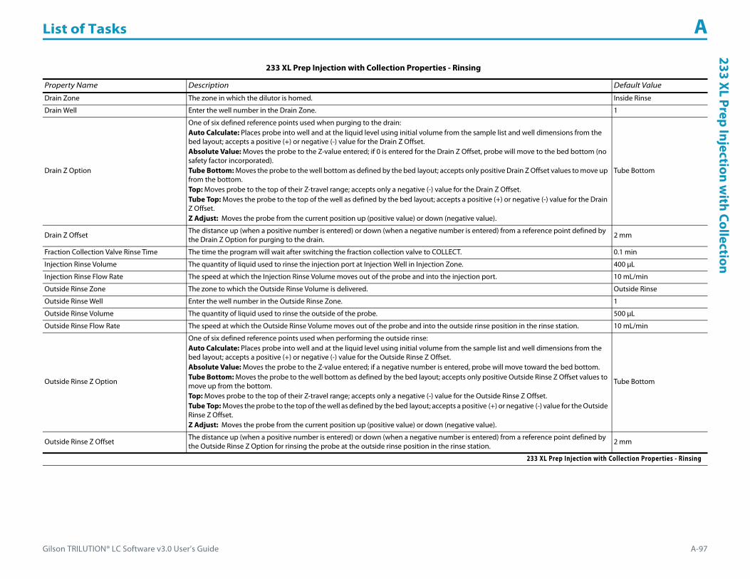
Gilson TRILUTION® LC Software v3.0 User’s Guide A-97
List of Tasks A233 XL Prep Injection w
ith Collection
233 XL Prep Injection with Collection Properties - Rinsing
Property Name Description Default Value
Drain Zone The zone in which the dilutor is homed. Inside Rinse
Drain Well Enter the well number in the Drain Zone. 1
Drain Z Option
One of six defined reference points used when purging to the drain:Auto Calculate: Places probe into well and at the liquid level using initial volume from the sample list and well dimensions from the bed layout; accepts a positive (+) or negative (-) value for the Drain Z Offset.Absolute Value: Moves the probe to the Z-value entered; if 0 is entered for the Drain Z Offset, probe will move to the bed bottom (no safety factor incorporated).Tube Bottom: Moves the probe to the well bottom as defined by the bed layout; accepts only positive Drain Z Offset values to move up from the bottom.Top: Moves probe to the top of their Z-travel range; accepts only a negative (-) value for the Drain Z Offset.Tube Top: Moves the probe to the top of the well as defined by the bed layout; accepts a positive (+) or negative (-) value for the Drain Z Offset.Z Adjust: Moves the probe from the current position up (positive value) or down (negative value).
Tube Bottom
Drain Z Offset The distance up (when a positive number is entered) or down (when a negative number is entered) from a reference point defined by the Drain Z Option for purging to the drain. 2 mm
Fraction Collection Valve Rinse Time The time the program will wait after switching the fraction collection valve to COLLECT. 0.1 min
Injection Rinse Volume The quantity of liquid used to rinse the injection port at Injection Well in Injection Zone. 400 μL
Injection Rinse Flow Rate The speed at which the Injection Rinse Volume moves out of the probe and into the injection port. 10 mL/min
Outside Rinse Zone The zone to which the Outside Rinse Volume is delivered. Outside Rinse
Outside Rinse Well Enter the well number in the Outside Rinse Zone. 1
Outside Rinse Volume The quantity of liquid used to rinse the outside of the probe. 500 μL
Outside Rinse Flow Rate The speed at which the Outside Rinse Volume moves out of the probe and into the outside rinse position in the rinse station. 10 mL/min
Outside Rinse Z Option
One of six defined reference points used when performing the outside rinse:Auto Calculate: Places probe into well and at the liquid level using initial volume from the sample list and well dimensions from the bed layout; accepts a positive (+) or negative (-) value for the Outside Rinse Z Offset.Absolute Value: Moves the probe to the Z-value entered; if a negative number is entered, probe will move toward the bed bottom.Tube Bottom: Moves the probe to the well bottom as defined by the bed layout; accepts only positive Outside Rinse Z Offset values to move up from the bottom.Top: Moves probe to the top of their Z-travel range; accepts only a negative (-) value for the Outside Rinse Z Offset.Tube Top: Moves the probe to the top of the well as defined by the bed layout; accepts a positive (+) or negative (-) value for the Outside Rinse Z Offset.Z Adjust: Moves the probe from the current position up (positive value) or down (negative value).
Tube Bottom
Outside Rinse Z Offset The distance up (when a positive number is entered) or down (when a negative number is entered) from a reference point defined by the Outside Rinse Z Option for rinsing the probe at the outside rinse position in the rinse station. 2 mm
233 XL Prep Injection with Collection Properties - Rinsing

List of Tasks A
A-98 Gilson TRILUTION® LC Software v3.0 User’s Guide
233
XL P
rep
Inje
ctio
n w
ith
Colle
ctio
n 233 XL Prep Injection with Collection - Sequence of StepsThe following is an overview for the sequence of steps.
1 Initialize2 Aspirate3 Inject4 Injection Port Rinse5 Outside Rinse
Initialize1 Move Z to Z Safe Height.2 Set injection valve to INJECT.3 Set switching valve to LOAD.4 Move to Drain Well in Drain Zone.5 Lower probe into well to Drain Z Option and Drain Z Offset.6 Home dilutor.7 Switch fraction collection valve to COLLECT for Fraction Collection Valve Rinse Time.8 Move Z to Z Safe Height.
Aspirate1 Switch dilutor valve to probe and aspirate Air Gap Volume at Air Gap Flow Rate.2 Switch dilutor valve to reservoir and aspirate Push Volume at Aspirate Flow Rate.3 Move to Sample Well in Sample Zone.4 Lower probe into well to Sample Z Option and Sample Z Offset.5 Switch dilutor valve to probe and aspirate Injection Volume at Aspirate Flow Rate.6 Move Z to Z Safe Height.

Gilson TRILUTION® LC Software v3.0 User’s Guide A-99
List of Tasks A233 XL Prep Injection w
ith Collection
Inject1 Move to Injection Well in Injection Zone.2 Lower probe into well to Injection Z Option and Injection Z Offset.3 Switch injection valve to LOAD.4 Wait 1.2 sec.5 Dispense Injection Volume + Push Volume at Dispense Flow Rate.6 Wait Injection Equilibration Time.7 Synchronize.8 Switch injection valve to INJECT.
Injection Port Rinse1 Home dilutor.2 Switch dilutor valve to reservoir and aspirate Injection Rinse Volume or syringe capacity at Injection Rinse Flow Rate.3 Switch dilutor valve to probe and dispense Injection Rinse Volume or syringe capacity at Injection Rinse Flow Rate.4 Repeat steps 2–3 until requested rinse volume is aspirated and dispensed.5 Move Z to Z Safe Height.
Outside Rinse1 Move to Outside Rinse Well in Outside Rinse Zone.2 Lower probe into well to Outside Rinse Z Option and Outside Rinse Z Offset.3 Home dilutor.4 Switch dilutor valve to reservoir and aspirate Outside Rinse Volume or syringe capacity at Outside Rinse Flow Rate.5 Switch dilutor valve to probe and dispense Outside Rinse Volume or syringe capacity at Outside Rinse Flow Rate.6 Repeat steps 4–5 until requested rinse volume is aspirated and dispensed.7 Move Z to Z Safe Height.

List of Tasks A
A-100 Gilson TRILUTION® LC Software v3.0 User’s Guide
234
Part
ial L
oop
Inje
ctio
n 234 Partial Loop InjectionThis task performs a partial loop injection.
For more information about the properties on each tab, refer to:
234 Partial Loop Injection Properties - Main
234 Partial Loop Injection Properties - Advanced
234 Partial Loop Injection Properties - Rinsing
234 Partial Loop Injection - Sequence of Steps
234 Partial Loop Injection Properties - Main
Property Name Description Default Value
Autoinjector The autoinjector that the task will affect. Liquid Handler
Sample Zone The zone from which the Injection Volume and Extra Volume are aspirated. Sample Zone
Sample Well Enter the well number in the Sample Zone. 0
Injection Zone The zone to which the Extra Volume and Injection Volume are dispensed. Injection Zone
Injection Well Enter the well number in the Injection Zone. 1
234 Partial Loop Injection Properties - Main (Page 1 of 2)

Gilson TRILUTION® LC Software v3.0 User’s Guide A-101
List of Tasks A234 Partial Loop Injection
Air Gap Volume The quantity of an air gap. 3 μL
Injection Volume The volume of sample to be injected. 0 μL
Extra Volume An additional volume to the first volume aspirated. It ensures that the actual volume of liquid to be transferred is not contaminated, and acts as an extra buffer between the air gap/reservoir solvent and the Injection Volume. 6 μL
234 Partial Loop Injection Properties - Advanced
Property Name Description Default Value
Aspirate Flow Rate The speed at which liquid volumes move into the probe. 0.3 mL/min
Dispense Flow Rate The speed at which liquid volumes move out of the probe. 0.3 mL/min
Air Gap Flow Rate The speed at which the Air Gap Volume moves into the probe. 0.3 mL/min
Injection Equilibration Time Time the program waits after loading the Extra Volume, Injection Volume, and Push Volume in the sample loop. 0.05 min
Sample Z Option
One of six defined reference points used when aspirating the Injection Volume and Extra Volume from the bed:Auto Calculate: Places probe into well and at the liquid level using initial volume from the sample list and well dimensions from the bed layout; accepts a positive (+) or negative (-) value for the Sample Z Offset.Absolute Value: Moves the probe to the Z-value entered; if a negative number is entered, probe will move toward the bed bottom.Tube Bottom: Moves the probe to the well bottom as defined by the bed layout; accepts only positive Sample Z Offset value to move up from the bottom.Top: Moves probe to the top of their Z-travel range; accepts only a negative (-) value for the Sample Z Offset.Tube Top: Moves the probe to the top of the well as defined by the bed layout; accepts a positive (+) or negative (-) value for the Sample Z Offset.Z Adjust: Moves the probe from the current position up (positive value) or down (negative value).
Tube Bottom
Sample Z Offset The distance up (when a positive number is entered) or down (when a negative number is entered) from a reference point defined by the Sample Z Option used when aspirating the Injection Volume and Extra Volume from the bed. 2 mm
Liquid Level FollowingWhen selected, the probe will follow the liquid down as it is aspirated from the Sample Zone. The Sample Z Option must be set to AUTO CALCULATE and initial volumes must be set in the sample list to use this option.
When cleared, the probe will not follow the liquid down as it is aspirated from the Sample Zone.Cleared
Injection Z Option
One of six defined reference points used when injecting the Injection Volume and Extra Volume:Auto Calculate: Places probe into well and at the liquid level using initial volume from the sample list and well dimensions from the bed layout; accepts a positive (+) or negative (-) value for the Injection Z Offset.Absolute Value: Moves the probe to the Z-value entered; if a negative number is entered, probe will move toward the bed bottom.Tube Bottom: Moves the probe to the well bottom as defined by the bed layout; accepts only positive Injection Z Offset value to move up from the bottom.Top: Moves probe to the top of their Z-travel range; accepts only a negative (-) value for the Injection Z Offset.Tube Top: Moves the probe to the top of the well as defined by the bed layout; accepts a positive (+) or negative (-) value for the Injection Z Offset.Z Adjust: Moves the probe from the current position up (positive value) or down (negative value).
Tube Bottom
Injection Z Offset The distance up (when a positive number is entered) or down (when a negative number is entered) from a reference point defined by the Injection Z Option used when injecting the Injection Volume and Extra Volume. 1 mm
234 Partial Loop Injection Properties - Advanced
234 Partial Loop Injection Properties - Main (Continued)
Property Name Description Default Value
234 Partial Loop Injection Properties - Main (Page 2 of 2)

List of Tasks A
A-102 Gilson TRILUTION® LC Software v3.0 User’s Guide
234
Part
ial L
oop
Inje
ctio
n
234 Partial Loop Injection Properties - Rinsing
Property Name Description Default Value
Drain Zone The zone in which the dilutor is homed. Inside Rinse
Drain Well Enter the well number in the Drain Zone. 1
Drain Z Option
One of six defined reference points used when purging to the drain:Auto Calculate: Places probe into well and at the liquid level using initial volume from the sample list and well dimensions from the bed layout; accepts a positive (+) or negative (-) value for the Drain Z Offset.Absolute Value: Moves the probe to the Z-value entered; if 0 is entered for the Drain Z Offset, probe will move to the bed bottom (no safety factor incorporated).Tube Bottom: Moves the probe to the well bottom as defined by the bed layout; accepts only positive Drain Z Offset values to move up from the bottom.Top: Moves probe to the top of their Z-travel range; accepts only a negative (-) value for the Drain Z Offset.Tube Top: Moves the probe to the top of the well as defined by the bed layout; accepts a positive (+) or negative (-) value for the Drain Z Offset.Z Adjust: Moves the probe from the current position up (positive value) or down (negative value).
Tube Bottom
Drain Z Offset The distance up (when a positive number is entered) or down (when a negative number is entered) from a reference point defined by the Drain Z Option for purging to the drain. 2 mm
Injection Rinse Volume The quantity of liquid used to rinse the injection port at Injection Well in Injection Zone. 250 μL
Injection Rinse Flow Rate The speed at which the Injection Rinse Volume moves out of the probe and into the injection port. 3 mL/min
Outside Rinse Zone The zone to which the Outside Rinse Volume is delivered. Outside Rinse
Outside Rinse Well Enter the well number in the Outside Rinse Zone. 1
Outside Rinse Volume The quantity of liquid used to rinse the outside of the probe. 300 μL
Outside Rinse Flow Rate The speed at which the Outside Rinse Volume moves out of the probe and into the outside rinse position in the rinse station. 3 mL/min
Outside Rinse Z Option
One of six defined reference points used when performing the outside rinse:Auto Calculate: Places probe into well and at the liquid level using initial volume from the sample list and well dimensions from the bed layout; accepts a positive (+) or negative (-) value for the Outside Rinse Z Offset.Absolute Value: Moves the probe to the Z-value entered; if a negative number is entered, probe will move toward the bed bottom.Tube Bottom: Moves the probe to the well bottom as defined by the bed layout; accepts only positive Outside Rinse Z Offset values to move up from the bottom.Top: Moves probe to the top of their Z-travel range; accepts only a negative (-) value for the Outside Rinse Z Offset.Tube Top: Moves the probe to the top of the well as defined by the bed layout; accepts a positive (+) or negative (-) value for the Outside Rinse Z Offset.Z Adjust: Moves the probe from the current position up (positive value) or down (negative value).
Tube Bottom
Outside Rinse Z Offset The distance up (when a positive number is entered) or down (when a negative number is entered) from a reference point defined by the Outside Rinse Z Option for rinsing the probe at the outside rinse position in the rinse station. 2 mm
234 Partial Loop Injection Properties - Rinsing

Gilson TRILUTION® LC Software v3.0 User’s Guide A-103
List of Tasks A234 Partial Loop Injection
234 Partial Loop Injection - Sequence of StepsThe following is an overview for the sequence of steps.
1 Initialize2 Aspirate3 Inject4 Injection Port Rinse5 Outside Rinse
Initialize1 Move Z to Z Safe Height.2 Set injection valve to INJECT.3 Move to Drain Well in Drain Zone.4 Lower probe into well to Drain Z Option and Drain Z Offset.5 Home dilutor.6 Move Z to Z Safe Height.
Aspirate1 Aspirate Air Gap Volume at Air Gap Flow Rate.2 Move to Sample Well in Sample Zone.3 Lower probe into well to Sample Z Option and Sample Z Offset.4 Aspirate Injection Volume + Extra Volume at Aspirate Flow Rate.5 Move Z to Z Safe Height.
Inject1 Move to Injection Well in Injection Zone.2 Lower probe into well to Injection Z Option and Injection Z Offset.3 Dispense Extra Volume at Dispense Flow Rate.4 Switch injection valve to LOAD.5 Wait 1.2 sec.6 Dispense Injection Volume at Dispense Flow Rate.7 Wait Injection Equilibration Time.8 Synchronize.

List of Tasks A
A-104 Gilson TRILUTION® LC Software v3.0 User’s Guide
234
Part
ial L
oop
Inje
ctio
n Injection Port Rinse1 Home dilutor.2 Switch dilutor valve to reservoir and aspirate Injection Rinse Volume or syringe capacity at Injection Rinse Flow Rate.3 Switch dilutor valve to probe and dispense Injection Rinse Volume or syringe capacity at Injection Rinse Flow Rate.4 Repeat steps 2–3 until requested rinse volume is aspirated and dispensed.5 Move Z to Z Safe Height.
Outside Rinse1 Move to Outside Rinse Well in Outside Rinse Zone.2 Lower probe into well to Outside Rinse Z Option and Outside Rinse Z Offset.3 Home dilutor.4 Switch dilutor valve to reservoir and aspirate Outside Rinse Volume or syringe capacity at Outside Rinse Flow Rate.5 Switch dilutor valve to probe and dispense Outside Rinse Volume or syringe capacity at Outside Rinse Flow Rate.6 Repeat steps 4–5 until requested rinse volume is aspirated and dispensed.7 Move Z to Z Safe Height.

Gilson TRILUTION® LC Software v3.0 User’s Guide A-105
List of Tasks A234 Total Loop Injection
234 Total Loop InjectionThis task performs a total loop injection.
For more information about the properties on each tab, refer to:
234 Total Loop Injection Properties - Main
234 Total Loop Injection Properties - Advanced
234 Total Loop Injection Properties - Rinsing
234 Total Loop Injection - Sequence of Steps
234 Total Loop Injection Properties - Main
Property Name Description Default Value
Autoinjector The autoinjector that the task will affect. Liquid Handler
Sample Zone The zone from which the Injection Volume and Extra Volume are aspirated. Sample Zone
Sample Well Enter the well number in the Sample Zone. 0
Injection Zone The zone to which the Extra Volume, Injection Volume, and Push Volume are dispensed. Injection Zone
Injection Well Enter the well number in the Injection Zone. 1
234 Total Loop Injection Properties - Main (Page 1 of 2)
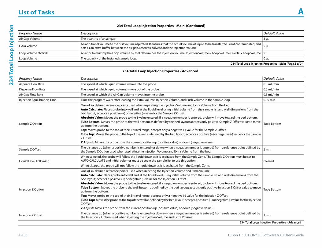
List of Tasks A
A-106 Gilson TRILUTION® LC Software v3.0 User’s Guide
234
Tota
l Loo
p In
ject
ion
Air Gap Volume The quantity of an air gap. 3 μL
Extra Volume An additional volume to the first volume aspirated. It ensures that the actual volume of liquid to be transferred is not contaminated, and acts as an extra buffer between the air gap/reservoir solvent and the Injection Volume. 5 μL
Loop Volume Overfill A factor to multiply the Loop Volume by that determines the injection volume. Injection Volume = Loop Volume Overfill x Loop Volume. 5
Loop Volume The capacity of the installed sample loop. 0 μL
234 Total Loop Injection Properties - Advanced
Property Name Description Default Value
Aspirate Flow Rate The speed at which liquid volumes move into the probe. 0.3 mL/min
Dispense Flow Rate The speed at which liquid volumes move out of the probe. 0.3 mL/min
Air Gap Flow Rate The speed at which the Air Gap Volume moves into the probe. 0.3 mL/min
Injection Equilibration Time Time the program waits after loading the Extra Volume, Injection Volume, and Push Volume in the sample loop. 0.05 min
Sample Z Option
One of six defined reference points used when aspirating the Injection Volume and Extra Volume from the bed:Auto Calculate: Places probe into well and at the liquid level using initial volume from the sample list and well dimensions from the bed layout; accepts a positive (+) or negative (-) value for the Sample Z Offset.Absolute Value: Moves the probe to the Z-value entered; if a negative number is entered, probe will move toward the bed bottom.Tube Bottom: Moves the probe to the well bottom as defined by the bed layout; accepts only positive Sample Z Offset value to move up from the bottom.Top: Moves probe to the top of their Z-travel range; accepts only a negative (-) value for the Sample Z Offset.Tube Top: Moves the probe to the top of the well as defined by the bed layout; accepts a positive (+) or negative (-) value for the Sample Z Offset.Z Adjust: Moves the probe from the current position up (positive value) or down (negative value).
Tube Bottom
Sample Z Offset The distance up (when a positive number is entered) or down (when a negative number is entered) from a reference point defined by the Sample Z Option used when aspirating the Injection Volume and Extra Volume from the bed. 2 mm
Liquid Level FollowingWhen selected, the probe will follow the liquid down as it is aspirated from the Sample Zone. The Sample Z Option must be set to AUTO CALCULATE and initial volumes must be set in the sample list to use this option.
When cleared, the probe will not follow the liquid down as it is aspirated from the Sample Zone.Cleared
Injection Z Option
One of six defined reference points used when injecting the Injection Volume and Extra Volume:Auto Calculate: Places probe into well and at the liquid level using initial volume from the sample list and well dimensions from the bed layout; accepts a positive (+) or negative (-) value for the Injection Z Offset.Absolute Value: Moves the probe to the Z-value entered; if a negative number is entered, probe will move toward the bed bottom.Tube Bottom: Moves the probe to the well bottom as defined by the bed layout; accepts only positive Injection Z Offset value to move up from the bottom.Top: Moves probe to the top of their Z-travel range; accepts only a negative (-) value for the Injection Z Offset.Tube Top: Moves the probe to the top of the well as defined by the bed layout; accepts a positive (+) or negative (-) value for the Injection Z Offset.Z Adjust: Moves the probe from the current position up (positive value) or down (negative value).
Tube Bottom
Injection Z Offset The distance up (when a positive number is entered) or down (when a negative number is entered) from a reference point defined by the Injection Z Option used when injecting the Injection Volume and Extra Volume. 1 mm
234 Total Loop Injection Properties - Advanced
234 Total Loop Injection Properties - Main (Continued)
Property Name Description Default Value
234 Total Loop Injection Properties - Main (Page 2 of 2)

Gilson TRILUTION® LC Software v3.0 User’s Guide A-107
List of Tasks A234 Total Loop Injection
234 Total Loop Injection Properties - Rinsing
Property Name Description Default Value
Drain Zone The zone in which the dilutor is homed. Inside Rinse
Drain Well Enter the well number in the Drain Zone. 1
Drain Z Option
One of six defined reference points used when purging to the drain:Auto Calculate: Places probe into well and at the liquid level using initial volume from the sample list and well dimensions from the bed layout; accepts a positive (+) or negative (-) value for the Drain Z Offset.Absolute Value: Moves the probe to the Z-value entered; if 0 is entered for the Drain Z Offset, probe will move to the bed bottom (no safety factor incorporated).Tube Bottom: Moves the probe to the well bottom as defined by the bed layout; accepts only positive Drain Z Offset values to move up from the bottom.Top: Moves probe to the top of their Z-travel range; accepts only a negative (-) value for the Drain Z Offset.Tube Top: Moves the probe to the top of the well as defined by the bed layout; accepts a positive (+) or negative (-) value for the Drain Z Offset.Z Adjust: Moves the probe from the current position up (positive value) or down (negative value).
Tube Bottom
Drain Z Offset The distance up (when a positive number is entered) or down (when a negative number is entered) from a reference point defined by the Drain Z Option for purging to the drain. 2 mm
Injection Rinse Volume The quantity of liquid used to rinse the injection port at Injection Well in Injection Zone. 250 μL
Injection Rinse Flow Rate The speed at which the Injection Rinse Volume moves out of the probe and into the injection port. 3 mL/min
Outside Rinse Zone The zone to which the Outside Rinse Volume is delivered. Outside Rinse
Outside Rinse Well Enter the well number in the Outside Rinse Zone. 1
Outside Rinse Volume The quantity of liquid used to rinse the outside of the probe. 300 μL
Outside Rinse Flow Rate The speed at which the Outside Rinse Volume moves out of the probe and into the outside rinse position in the rinse station. 3 mL/min
Outside Rinse Z Option
One of six defined reference points used when performing the outside rinse:Auto Calculate: Places probe into well and at the liquid level using initial volume from the sample list and well dimensions from the bed layout; accepts a positive (+) or negative (-) value for the Outside Rinse Z Offset.Absolute Value: Moves the probe to the Z-value entered; if a negative number is entered, probe will move toward the bed bottom.Tube Bottom: Moves the probe to the well bottom as defined by the bed layout; accepts only positive Outside Rinse Z Offset values to move up from the bottom.Top: Moves probe to the top of their Z-travel range; accepts only a negative (-) value for the Outside Rinse Z Offset.Tube Top: Moves the probe to the top of the well as defined by the bed layout; accepts a positive (+) or negative (-) value for the Outside Rinse Z Offset.Z Adjust: Moves the probe from the current position up (positive value) or down (negative value).
Tube Bottom
Outside Rinse Z Offset The distance up (when a positive number is entered) or down (when a negative number is entered) from a reference point defined by the Outside Rinse Z Option for rinsing the probe at the outside rinse position in the rinse station. 2 mm
234 Total Loop Injection Properties - Rinsing
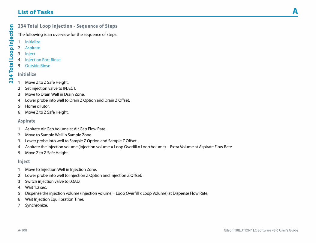
List of Tasks A
A-108 Gilson TRILUTION® LC Software v3.0 User’s Guide
234
Tota
l Loo
p In
ject
ion 234 Total Loop Injection - Sequence of Steps
The following is an overview for the sequence of steps.
1 Initialize2 Aspirate3 Inject4 Injection Port Rinse5 Outside Rinse
Initialize1 Move Z to Z Safe Height.2 Set injection valve to INJECT.3 Move to Drain Well in Drain Zone.4 Lower probe into well to Drain Z Option and Drain Z Offset.5 Home dilutor.6 Move Z to Z Safe Height.
Aspirate1 Aspirate Air Gap Volume at Air Gap Flow Rate.2 Move to Sample Well in Sample Zone.3 Lower probe into well to Sample Z Option and Sample Z Offset.4 Aspirate the injection volume (injection volume = Loop Overfill x Loop Volume) + Extra Volume at Aspirate Flow Rate.5 Move Z to Z Safe Height.
Inject1 Move to Injection Well in Injection Zone.2 Lower probe into well to Injection Z Option and Injection Z Offset.3 Switch injection valve to LOAD.4 Wait 1.2 sec.5 Dispense the injection volume (injection volume = Loop Overfill x Loop Volume) at Dispense Flow Rate.6 Wait Injection Equilibration Time.7 Synchronize.

Gilson TRILUTION® LC Software v3.0 User’s Guide A-109
List of Tasks A234 Total Loop Injection
Injection Port Rinse1 Home dilutor.2 Switch dilutor valve to reservoir and aspirate Injection Rinse Volume or syringe capacity at Injection Rinse Flow Rate.3 Switch dilutor valve to probe and dispense Injection Rinse Volume or syringe capacity at Injection Rinse Flow Rate.4 Repeat steps 2–3 until requested rinse volume is aspirated and dispensed.5 Move Z to Z Safe Height.
Outside Rinse1 Move to Outside Rinse Well in Outside Rinse Zone.2 Lower probe into well to Outside Rinse Z Option and Outside Rinse Z Offset.3 Home dilutor.4 Switch dilutor valve to reservoir and aspirate Outside Rinse Volume or syringe capacity at Outside Rinse Flow Rate.5 Switch dilutor valve to probe and dispense Outside Rinse Volume or syringe capacity at Outside Rinse Flow Rate.6 Repeat steps 4–5 until requested rinse volume is aspirated and dispensed.7 Move Z to Z Safe Height.
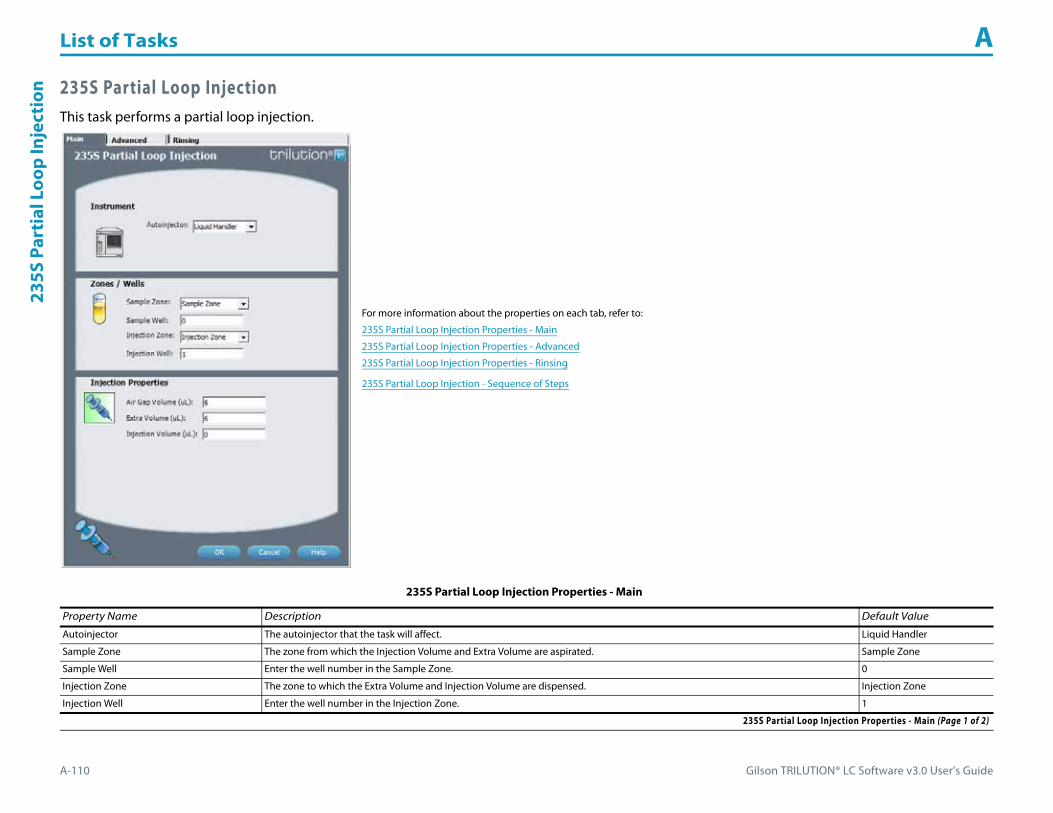
List of Tasks A
A-110 Gilson TRILUTION® LC Software v3.0 User’s Guide
235S
Par
tial
Loo
p In
ject
ion 235S Partial Loop Injection
This task performs a partial loop injection.
For more information about the properties on each tab, refer to:
235S Partial Loop Injection Properties - Main
235S Partial Loop Injection Properties - Advanced
235S Partial Loop Injection Properties - Rinsing
235S Partial Loop Injection - Sequence of Steps
235S Partial Loop Injection Properties - Main
Property Name Description Default Value
Autoinjector The autoinjector that the task will affect. Liquid Handler
Sample Zone The zone from which the Injection Volume and Extra Volume are aspirated. Sample Zone
Sample Well Enter the well number in the Sample Zone. 0
Injection Zone The zone to which the Extra Volume and Injection Volume are dispensed. Injection Zone
Injection Well Enter the well number in the Injection Zone. 1
235S Partial Loop Injection Properties - Main (Page 1 of 2)

Gilson TRILUTION® LC Software v3.0 User’s Guide A-111
List of Tasks A235S Partial Loop Injection
Air Gap Volume The quantity of an air gap. 6 μL
Extra Volume An additional volume to the first volume aspirated. It ensures that the actual volume of liquid to be transferred is not contaminated, and acts as an extra buffer between the air gap/reservoir solvent and the Injection Volume. 6 μL
Injection Volume The volume of sample to be injected. 0 μL
235S Partial Loop Injection Properties - Advanced
Property Name Description Default Value
Aspirate Flow Rate The speed at which liquid volumes move into the probe. 0.5 mL/min
Dispense Flow Rate The speed at which liquid volumes move out of the probe. 0.3 mL/min
Air Gap Flow Rate The speed at which the Air Gap Volume moves into the probe. 0.3 mL/min
Injection Equilibration Time Time the program waits after loading the Extra Volume, Injection Volume, and Push Volume in the sample loop. 0.05 min
Sample Z Option
One of six defined reference points used when aspirating the Injection Volume and Extra Volume from the bed:Auto Calculate: Places probe into well and at the liquid level using initial volume from the sample list and well dimensions from the bed layout; accepts a positive (+) or negative (-) value for the Sample Z Offset.Absolute Value: Moves the probe to the Z-value entered; if 0 is entered, probe will move to the bed bottom (no safety factor incorporated).Tube Bottom: Moves the probe to the well bottom as defined by the bed layout; accepts only positive Sample Z Offset value to move up from the bottom.Top: Moves probe to the top of their Z-travel range; accepts only a negative (-) value for the Sample Z Offset.Tube Top: Moves the probe to the top of the well as defined by the bed layout; accepts a positive (+) or negative (-) value for the Sample Z Offset.Z Adjust: Moves the probe from the current position up (positive value) or down (negative value).
Tube Bottom
Sample Z Offset The distance up (when a positive number is entered) or down (when a negative number is entered) from a reference point defined by the Sample Z Option used when aspirating the Injection Volume and Extra Volume from the bed. 2 mm
Injection Z Option
One of six defined reference points used when injecting the Injection Volume and Extra Volume:Auto Calculate: Places probe into well and at the liquid level using initial volume from the sample list and well dimensions from the bed layout; accepts a positive (+) or negative (-) value for the Injection Z Offset.Absolute Value: Moves the probe to the Z-value entered; if 0 is entered, probe will move to the bed bottom (no safety factor incorporated).Tube Bottom: Moves the probe to the well bottom as defined by the bed layout; accepts only positive Injection Z Offset value to move up from the bottom.Top: Moves probe to the top of their Z-travel range; accepts only a negative (-) value for the Injection Z Offset.Tube Top: Moves the probe to the top of the well as defined by the bed layout; accepts a positive (+) or negative (-) value for the Injection Z Offset.Z Adjust: Moves the probe from the current position up (positive value) or down (negative value).
Tube Bottom
Injection Z Offset The distance up (when a positive number is entered) or down (when a negative number is entered) from a reference point defined by the Injection Z Option used when injecting the Injection Volume and Extra Volume. 0 mm
235S Partial Loop Injection Properties - Advanced
235S Partial Loop Injection Properties - Main (Continued)
Property Name Description Default Value
235S Partial Loop Injection Properties - Main (Page 2 of 2)

List of Tasks A
A-112 Gilson TRILUTION® LC Software v3.0 User’s Guide
235S
Par
tial
Loo
p In
ject
ion
235S Partial Loop Injection Properties - Rinsing
Property Name Description Default Value
Drain Zone The zone in which the dilutor is homed. Inside Rinse
Drain Well Enter the well number in the Drain Zone. 1
Drain Z Option
One of six defined reference points used when purging to the drain:Auto Calculate: Places probe into well and at the liquid level using initial volume from the sample list and well dimensions from the bed layout; accepts a positive (+) or negative (-) value for the Drain Z Offset.Absolute Value: Moves the probe to the Z-value entered; if 0 is entered for the Drain Z Offset, probe will move to the bed bottom (no safety factor incorporated).Tube Bottom: Moves the probe to the well bottom as defined by the bed layout; accepts only positive Drain Z Offset values to move up from the bottom.Top: Moves probe to the top of their Z-travel range; accepts only a negative (-) value for the Drain Z Offset.Tube Top: Moves the probe to the top of the well as defined by the bed layout; accepts a positive (+) or negative (-) value for the Drain Z Offset.Z Adjust: Moves the probe from the current position up (positive value) or down (negative value).
Tube Bottom
Drain Z Offset The distance up (when a positive number is entered) or down (when a negative number is entered) from a reference point defined by the Drain Z Option for purging to the drain. 2 mm
Injection Rinse Volume The quantity of liquid used to rinse the injection port at Injection Well in Injection Zone. 250 μL
Injection Rinse Flow Rate The speed at which the Injection Rinse Volume moves out of the probe and into the injection port. 3.3 mL/min
Outside Rinse Zone The zone to which the Outside Rinse Volume is delivered. Outside Rinse
Outside Rinse Well Enter the well number in the Outside Rinse Zone. 1
Outside Rinse Volume The quantity of liquid used to rinse the outside of the probe. 300 μL
Outside Rinse Flow Rate The speed at which the Outside Rinse Volume moves out of the probe and into the outside rinse position in the rinse station. 3.3 mL/min
Outside Rinse Z Option
One of six defined reference points used when performing the outside rinse:Auto Calculate: Places probe into well and at the liquid level using initial volume from the sample list and well dimensions from the bed layout; accepts a positive (+) or negative (-) value for the Outside Rinse Z Offset.Absolute Value: Moves the probe to the Z-value entered; if 0 is entered, probe will move to the bed bottom (no safety factor incorporated).Tube Bottom: Moves the probe to the well bottom as defined by the bed layout; accepts only positive Outside Rinse Z Offset values to move up from the bottom.Top: Moves probe to the top of their Z-travel range; accepts only a negative (-) value for the Outside Rinse Z Offset.Tube Top: Moves the probe to the top of the well as defined by the bed layout; accepts a positive (+) or negative (-) value for the Outside Rinse Z Offset.Z Adjust: Moves the probe from the current position up (positive value) or down (negative value).
Tube Bottom
Outside Rinse Z Offset The distance up (when a positive number is entered) or down (when a negative number is entered) from a reference point defined by the Outside Rinse Z Option for rinsing the probe at the outside rinse position in the rinse station. 2 mm
235S Partial Loop Injection Properties - Rinsing
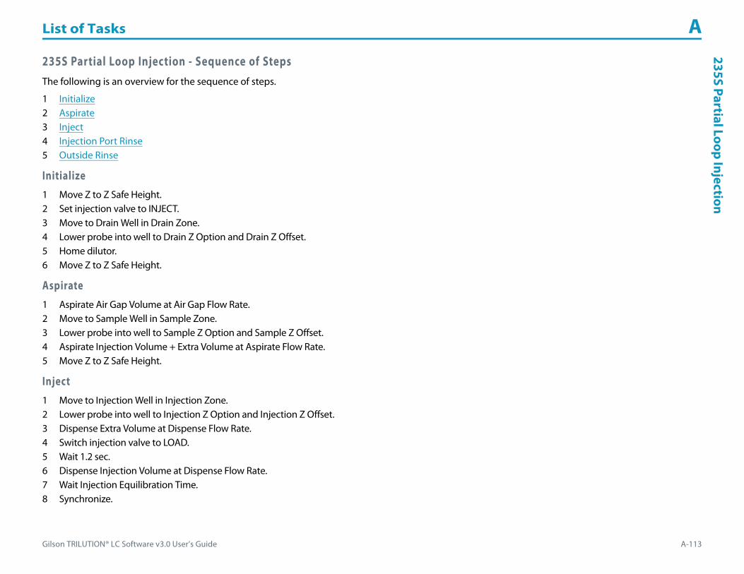
Gilson TRILUTION® LC Software v3.0 User’s Guide A-113
List of Tasks A235S Partial Loop Injection
235S Partial Loop Injection - Sequence of StepsThe following is an overview for the sequence of steps.
1 Initialize2 Aspirate3 Inject4 Injection Port Rinse5 Outside Rinse
Initialize1 Move Z to Z Safe Height.2 Set injection valve to INJECT.3 Move to Drain Well in Drain Zone.4 Lower probe into well to Drain Z Option and Drain Z Offset.5 Home dilutor.6 Move Z to Z Safe Height.
Aspirate1 Aspirate Air Gap Volume at Air Gap Flow Rate.2 Move to Sample Well in Sample Zone.3 Lower probe into well to Sample Z Option and Sample Z Offset.4 Aspirate Injection Volume + Extra Volume at Aspirate Flow Rate.5 Move Z to Z Safe Height.
Inject1 Move to Injection Well in Injection Zone.2 Lower probe into well to Injection Z Option and Injection Z Offset.3 Dispense Extra Volume at Dispense Flow Rate.4 Switch injection valve to LOAD.5 Wait 1.2 sec.6 Dispense Injection Volume at Dispense Flow Rate.7 Wait Injection Equilibration Time.8 Synchronize.
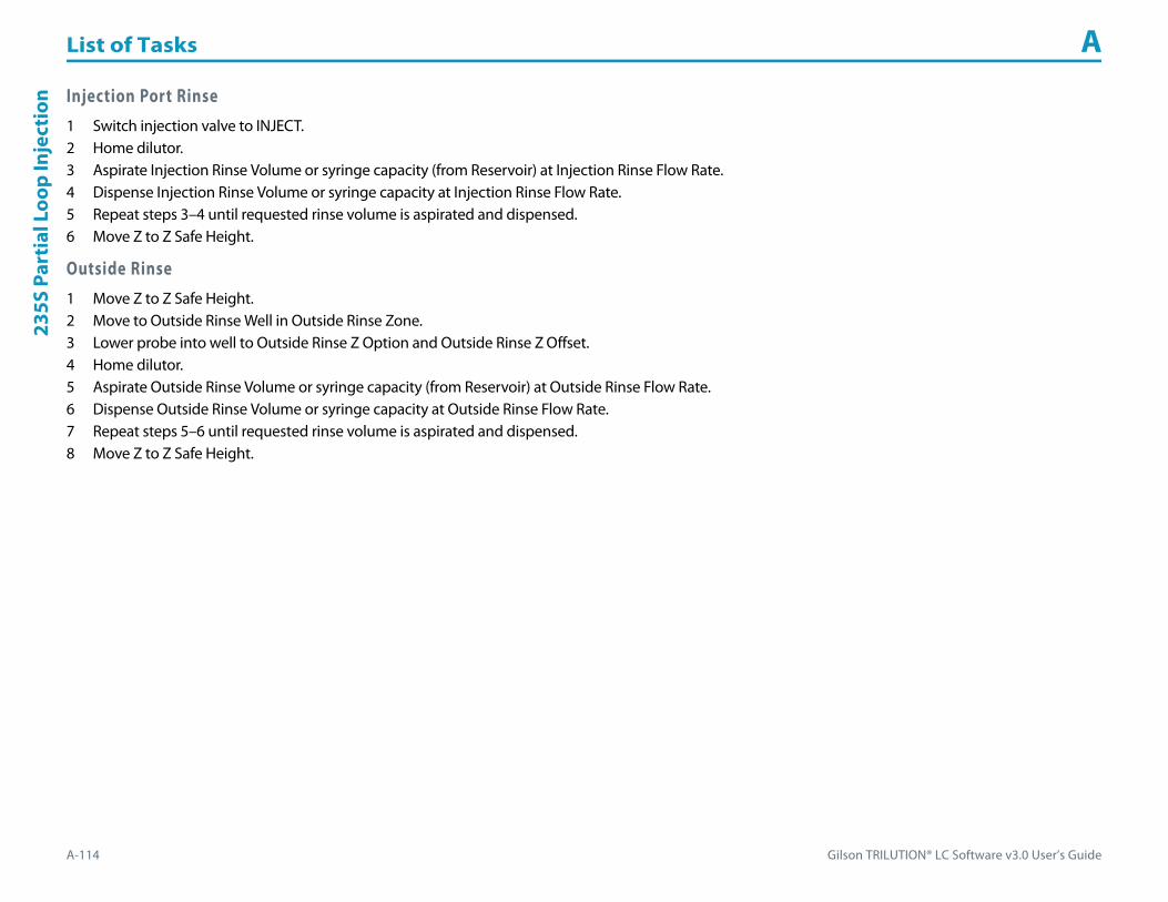
List of Tasks A
A-114 Gilson TRILUTION® LC Software v3.0 User’s Guide
235S
Par
tial
Loo
p In
ject
ion Injection Port Rinse
1 Switch injection valve to INJECT.2 Home dilutor.3 Aspirate Injection Rinse Volume or syringe capacity (from Reservoir) at Injection Rinse Flow Rate.4 Dispense Injection Rinse Volume or syringe capacity at Injection Rinse Flow Rate.5 Repeat steps 3–4 until requested rinse volume is aspirated and dispensed.6 Move Z to Z Safe Height.
Outside Rinse1 Move Z to Z Safe Height.2 Move to Outside Rinse Well in Outside Rinse Zone.3 Lower probe into well to Outside Rinse Z Option and Outside Rinse Z Offset.4 Home dilutor.5 Aspirate Outside Rinse Volume or syringe capacity (from Reservoir) at Outside Rinse Flow Rate.6 Dispense Outside Rinse Volume or syringe capacity at Outside Rinse Flow Rate.7 Repeat steps 5–6 until requested rinse volume is aspirated and dispensed.8 Move Z to Z Safe Height.
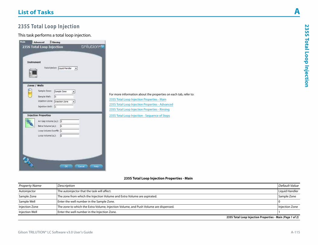
Gilson TRILUTION® LC Software v3.0 User’s Guide A-115
List of Tasks A235S Total Loop Injection
235S Total Loop InjectionThis task performs a total loop injection.
For more information about the properties on each tab, refer to:
235S Total Loop Injection Properties - Main
235S Total Loop Injection Properties - Advanced
235S Total Loop Injection Properties - Rinsing
235S Total Loop Injection - Sequence of Steps
235S Total Loop Injection Properties - Main
Property Name Description Default Value
Autoinjector The autoinjector that the task will affect. Liquid Handler
Sample Zone The zone from which the Injection Volume and Extra Volume are aspirated. Sample Zone
Sample Well Enter the well number in the Sample Zone. 0
Injection Zone The zone to which the Extra Volume, Injection Volume, and Push Volume are dispensed. Injection Zone
Injection Well Enter the well number in the Injection Zone. 1
235S Total Loop Injection Properties - Main (Page 1 of 2)
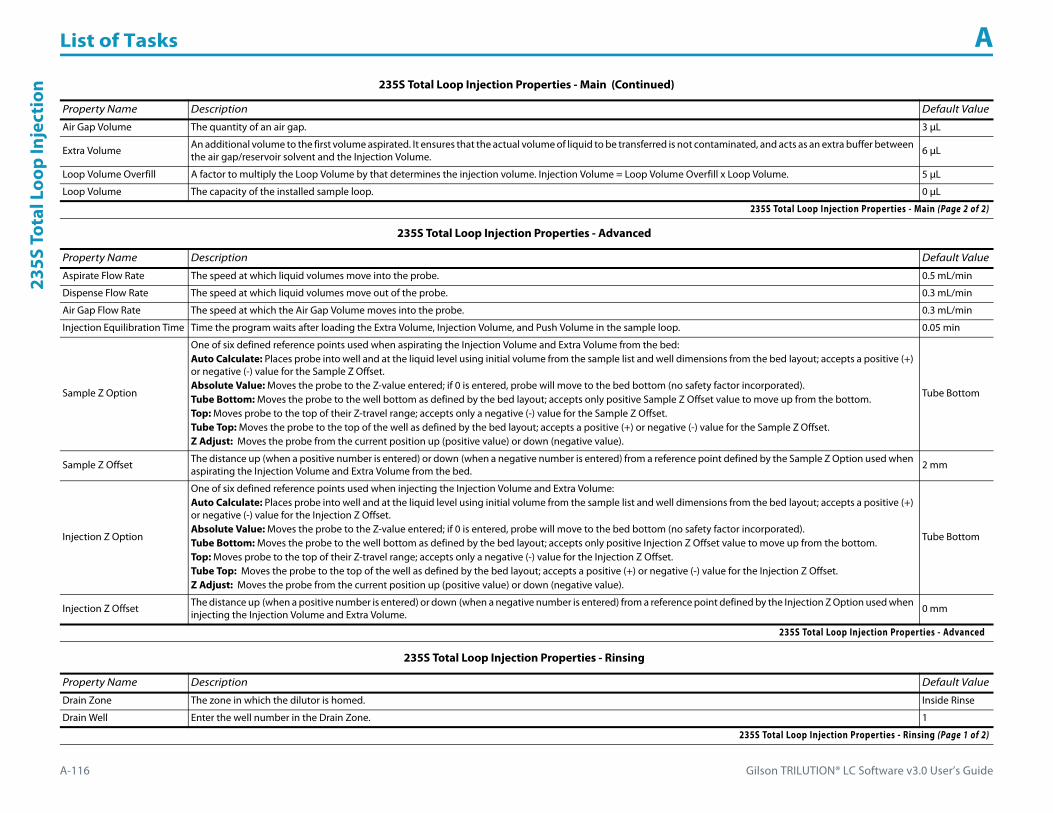
List of Tasks A
A-116 Gilson TRILUTION® LC Software v3.0 User’s Guide
235S
Tot
al L
oop
Inje
ctio
n
Air Gap Volume The quantity of an air gap. 3 μL
Extra Volume An additional volume to the first volume aspirated. It ensures that the actual volume of liquid to be transferred is not contaminated, and acts as an extra buffer between the air gap/reservoir solvent and the Injection Volume. 6 μL
Loop Volume Overfill A factor to multiply the Loop Volume by that determines the injection volume. Injection Volume = Loop Volume Overfill x Loop Volume. 5 μL
Loop Volume The capacity of the installed sample loop. 0 μL
235S Total Loop Injection Properties - Advanced
Property Name Description Default Value
Aspirate Flow Rate The speed at which liquid volumes move into the probe. 0.5 mL/min
Dispense Flow Rate The speed at which liquid volumes move out of the probe. 0.3 mL/min
Air Gap Flow Rate The speed at which the Air Gap Volume moves into the probe. 0.3 mL/min
Injection Equilibration Time Time the program waits after loading the Extra Volume, Injection Volume, and Push Volume in the sample loop. 0.05 min
Sample Z Option
One of six defined reference points used when aspirating the Injection Volume and Extra Volume from the bed:Auto Calculate: Places probe into well and at the liquid level using initial volume from the sample list and well dimensions from the bed layout; accepts a positive (+) or negative (-) value for the Sample Z Offset.Absolute Value: Moves the probe to the Z-value entered; if 0 is entered, probe will move to the bed bottom (no safety factor incorporated).Tube Bottom: Moves the probe to the well bottom as defined by the bed layout; accepts only positive Sample Z Offset value to move up from the bottom.Top: Moves probe to the top of their Z-travel range; accepts only a negative (-) value for the Sample Z Offset.Tube Top: Moves the probe to the top of the well as defined by the bed layout; accepts a positive (+) or negative (-) value for the Sample Z Offset.Z Adjust: Moves the probe from the current position up (positive value) or down (negative value).
Tube Bottom
Sample Z Offset The distance up (when a positive number is entered) or down (when a negative number is entered) from a reference point defined by the Sample Z Option used when aspirating the Injection Volume and Extra Volume from the bed. 2 mm
Injection Z Option
One of six defined reference points used when injecting the Injection Volume and Extra Volume:Auto Calculate: Places probe into well and at the liquid level using initial volume from the sample list and well dimensions from the bed layout; accepts a positive (+) or negative (-) value for the Injection Z Offset.Absolute Value: Moves the probe to the Z-value entered; if 0 is entered, probe will move to the bed bottom (no safety factor incorporated).Tube Bottom: Moves the probe to the well bottom as defined by the bed layout; accepts only positive Injection Z Offset value to move up from the bottom.Top: Moves probe to the top of their Z-travel range; accepts only a negative (-) value for the Injection Z Offset.Tube Top: Moves the probe to the top of the well as defined by the bed layout; accepts a positive (+) or negative (-) value for the Injection Z Offset.Z Adjust: Moves the probe from the current position up (positive value) or down (negative value).
Tube Bottom
Injection Z Offset The distance up (when a positive number is entered) or down (when a negative number is entered) from a reference point defined by the Injection Z Option used when injecting the Injection Volume and Extra Volume. 0 mm
235S Total Loop Injection Properties - Advanced
235S Total Loop Injection Properties - Rinsing
Property Name Description Default Value
Drain Zone The zone in which the dilutor is homed. Inside Rinse
Drain Well Enter the well number in the Drain Zone. 1
235S Total Loop Injection Properties - Rinsing (Page 1 of 2)
235S Total Loop Injection Properties - Main (Continued)
Property Name Description Default Value
235S Total Loop Injection Properties - Main (Page 2 of 2)

Gilson TRILUTION® LC Software v3.0 User’s Guide A-117
List of Tasks A235S Total Loop Injection
Drain Z Option
One of six defined reference points used when purging to the drain:Auto Calculate: Places probe into well and at the liquid level using initial volume from the sample list and well dimensions from the bed layout; accepts a positive (+) or negative (-) value for the Drain Z Offset.Absolute Value: Moves the probe to the Z-value entered; if 0 is entered for the Drain Z Offset, probe will move to the bed bottom (no safety factor incorporated).Tube Bottom: Moves the probe to the well bottom as defined by the bed layout; accepts only positive Drain Z Offset values to move up from the bottom.Top: Moves probe to the top of their Z-travel range; accepts only a negative (-) value for the Drain Z Offset.Tube Top: Moves the probe to the top of the well as defined by the bed layout; accepts a positive (+) or negative (-) value for the Drain Z Offset.Z Adjust: Moves the probe from the current position up (positive value) or down (negative value).
Tube Bottom
Drain Z Offset The distance up (when a positive number is entered) or down (when a negative number is entered) from a reference point defined by the Drain Z Option for purging to the drain.
2 mm
Injection Rinse Volume The quantity of liquid used to rinse the injection port at Injection Well in Injection Zone. 250 μL
Injection Rinse Flow Rate The speed at which the Injection Rinse Volume moves out of the probe and into the injection port. 3.3 mL/min
Outside Rinse Zone The zone to which the Outside Rinse Volume is delivered. Outside Rinse
Outside Rinse Well Enter the well number in the Outside Rinse Zone. 1
Outside Rinse Volume The quantity of liquid used to rinse the outside of the probe. 300 μL
Outside Rinse Flow Rate The speed at which the Outside Rinse Volume moves out of the probe and into the outside rinse position in the rinse station. 3.3 mL/min
Outside Rinse Z Option
One of six defined reference points used when performing the outside rinse:Auto Calculate: Places probe into well and at the liquid level using initial volume from the sample list and well dimensions from the bed layout; accepts a positive (+) or negative (-) value for the Outside Rinse Z Offset.Absolute Value: Moves the probe to the Z-value entered; if 0 is entered, probe will move to the bed bottom (no safety factor incorporated).Tube Bottom: Moves the probe to the well bottom as defined by the bed layout; accepts only positive Outside Rinse Z Offset values to move up from the bottom.Top: Moves probe to the top of their Z-travel range; accepts only a negative (-) value for the Outside Rinse Z Offset.Tube Top: Moves the probe to the top of the well as defined by the bed layout; accepts a positive (+) or negative (-) value for the Outside Rinse Z Offset.Z Adjust: Moves the probe from the current position up (positive value) or down (negative value).
Tube Bottom
Outside Rinse Z Offset The distance up (when a positive number is entered) or down (when a negative number is entered) from a reference point defined by the Outside Rinse Z Option for rinsing the probe at the outside rinse position in the rinse station. 2 mm
235S Total Loop Injection Properties - Rinsing (Continued)
Property Name Description Default Value
235S Total Loop Injection Properties - Rinsing (Page 2 of 2)

List of Tasks A
A-118 Gilson TRILUTION® LC Software v3.0 User’s Guide
235S
Tot
al L
oop
Inje
ctio
n 235S Total Loop Injection - Sequence of StepsThe following is an overview for the sequence of steps.
1 Initialize2 Aspirate3 Inject4 Injection Port Rinse5 Outside Rinse
Initialize1 Move Z to Z Safe Height.2 Set injection valve to INJECT.3 Move to Drain Well in Drain Zone.4 Lower probe into well to Drain Z Option and Drain Z Offset.5 Home dilutor.6 Move Z to Z Safe Height.
Aspirate1 Aspirate Air Gap Volume at Air Gap Flow Rate.2 Move to Sample Well in Sample Zone.3 Lower probe into well to Sample Z Option and Sample Z Offset.4 Aspirate the injection volume (injection volume = Loop Overfill x Loop Volume) + Extra Volume at Aspirate Flow Rate.5 Move Z to Z Safe Height.
Inject1 Move to Injection Well in Injection Zone.2 Lower probe into well to Injection Z Option and Injection Z Offset.3 Switch injection valve to LOAD.4 Wait 1.2 sec.5 Dispense the injection volume (injection volume = Loop Overfill x Loop Volume) at Dispense Flow Rate.6 Wait Injection Equilibration Time.7 Synchronize.

Gilson TRILUTION® LC Software v3.0 User’s Guide A-119
List of Tasks A235S Total Loop Injection
Injection Port Rinse1 Switch injection valve to INJECT.2 Home dilutor.3 Aspirate Injection Rinse Volume or syringe capacity (from Reservoir) at Injection Rinse Flow Rate.4 Dispense Injection Rinse Volume or syringe capacity at Injection Rinse Flow Rate.5 Repeat steps 3–4 until requested rinse volume is aspirated and dispensed.6 Move Z to Z Safe Height.
Outside Rinse1 Move Z to Z Safe Height.2 Move to Outside Rinse Well in Outside Rinse Zone.3 Lower probe into well to Outside Rinse Z Option and Outside Rinse Z Offset.4 Home dilutor.5 Aspirate Outside Rinse Volume or syringe capacity (from Reservoir) at Outside Rinse Flow Rate.6 Dispense Outside Rinse Volume or syringe capacity at Outside Rinse Flow Rate.7 Repeat steps 5–6 until requested rinse volume is aspirated and dispensed.8 Move Z to Z Safe Height.
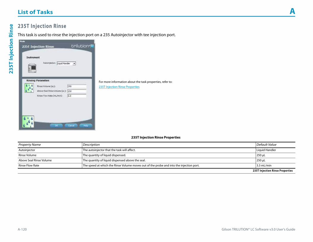
List of Tasks A
A-120 Gilson TRILUTION® LC Software v3.0 User’s Guide
235T
Inje
ctio
n Ri
nse 235T Injection Rinse
This task is used to rinse the injection port on a 235 Autoinjector with tee injection port.
For more information about the task properties, refer to:
235T Injection Rinse Properties
235T Injection Rinse Properties
Property Name Description Default Value
Autoinjector The autoinjector that the task will affect. Liquid Handler
Rinse Volume The quantity of liquid dispensed. 250 μL
Above Seal Rinse Volume The quantity of liquid dispensed above the seal. 250 μL
Rinse Flow Rate The speed at which the Rinse Volume moves out of the probe and into the injection port. 3.3 mL/min
235T Injection Rinse Properties

Gilson TRILUTION® LC Software v3.0 User’s Guide A-121
List of Tasks A235T Partial Loop Injection
235T Partial Loop InjectionThis task performs a partial loop injection on a 235 Autoinjector with a tee injection port.
For more information about the properties on each tab, refer to:
235T Partial Loop Injection Properties - Main
235T Partial Loop Injection Properties - Advanced
235T Partial Loop Injection Properties - Rinsing
235T Partial Loop Injection - Sequence of Steps
235T Partial Loop Injection Properties - Main
Property Name Description Default Value
Autoinjector The autoinjector that the task will affect. Liquid Handler
Sample Zone The zone from which the Injection Volume and Extra Volume are aspirated. Sample Zone
Sample Well Enter the well number in the Sample Zone. 0
Injection Zone The zone to which the Extra Volume and Injection Volume are dispensed. Injection Zone
235T Partial Loop Injection Properties - Main (Page 1 of 2)

List of Tasks A
A-122 Gilson TRILUTION® LC Software v3.0 User’s Guide
235T
Par
tial
Loo
p In
ject
ion
Injection Well Enter the well number in the Injection Zone. 1
Air Gap Volume The quantity of an air gap. 6 μL
Extra Volume An additional volume to the first volume aspirated. It ensures that the actual volume of liquid to be transferred is not contaminated, and acts as an extra buffer between the air gap/reservoir solvent and the Injection Volume. 6 μL
Injection Volume The volume of sample to be injected. 0 μL
235T Partial Loop Injection Properties - Advanced
Property Name Description Default Value
Aspirate Flow Rate The speed at which liquid volumes move into the probe. 0.5 mL/min
Dispense Flow Rate The speed at which liquid volumes move out of the probe. 0.3 mL/min
Air Gap Flow Rate The speed at which the Air Gap Volume moves into the probe. 0.3 mL/min
Injection Equilibration Time Time the program waits after loading the Extra Volume, Injection Volume, and Push Volume in the sample loop. 0.05 min
Sample Z Option
One of six defined reference points used when aspirating the Injection Volume and Extra Volume from the bed:Auto Calculate: Places probe into well and at the liquid level using initial volume from the sample list and well dimensions from the bed layout; accepts a positive (+) or negative (-) value for the Sample Z Offset.Absolute Value: Moves the probe to the Z-value entered; if 0 is entered, probe will move to the bed bottom (no safety factor incorporated).Tube Bottom: Moves the probe to the well bottom as defined by the bed layout; accepts only positive Sample Z Offset value to move up from the bottom.Top: Moves probe to the top of their Z-travel range; accepts only a negative (-) value for the Sample Z Offset.Tube Top: Moves the probe to the top of the well as defined by the bed layout; accepts a positive (+) or negative (-) value for the Sample Z Offset.Z Adjust: Moves the probe from the current position up (positive value) or down (negative value).
Tube Bottom
Sample Z Offset The distance up (when a positive number is entered) or down (when a negative number is entered) from a reference point defined by the Sample Z Option used when aspirating the Injection Volume and Extra Volume from the bed. 2 mm
Injection Z Option
One of six defined reference points used when injecting the Injection Volume and Extra Volume:Auto Calculate: Places probe into well and at the liquid level using initial volume from the sample list and well dimensions from the bed layout; accepts a positive (+) or negative (-) value for the Injection Z Offset.Absolute Value: Moves the probe to the Z-value entered; if 0 is entered, probe will move to the bed bottom (no safety factor incorporated).Tube Bottom: Moves the probe to the well bottom as defined by the bed layout; accepts only positive Injection Z Offset value to move up from the bottom.Top: Moves probe to the top of their Z-travel range; accepts only a negative (-) value for the Injection Z Offset.Tube Top: Moves the probe to the top of the well as defined by the bed layout; accepts a positive (+) or negative (-) value for the Injection Z Offset.Z Adjust: Moves the probe from the current position up (positive value) or down (negative value).
Tube Bottom
Injection Z Offset The distance up (when a positive number is entered) or down (when a negative number is entered) from a reference point defined by the Injection Z Option used when injecting the Injection Volume and Extra Volume. 0 mm
235T Partial Loop Injection Properties - Advanced
235T Partial Loop Injection Properties - Rinsing
Property Name Description Default Value
Drain Zone The zone in which the dilutor is homed. Inside Rinse
Drain Well Enter the well number in the Drain Zone. 1
235T Partial Loop Injection Properties - Rinsing (Page 1 of 2)
235T Partial Loop Injection Properties - Main (Continued)
Property Name Description Default Value
235T Partial Loop Injection Properties - Main (Page 2 of 2)
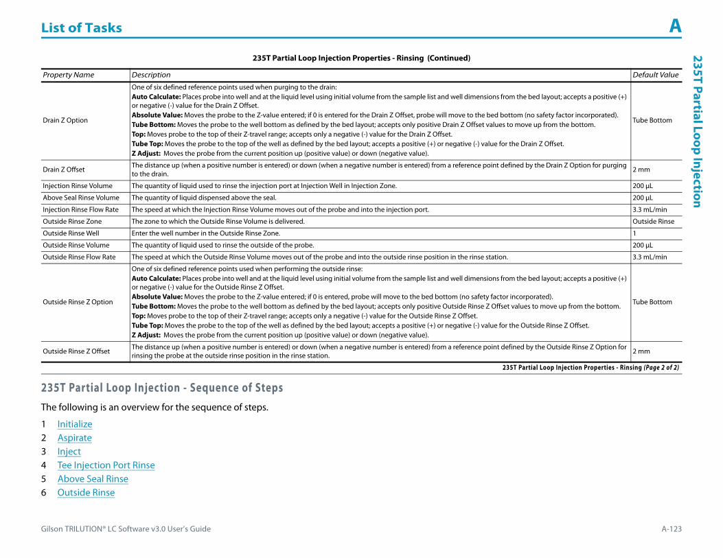
Gilson TRILUTION® LC Software v3.0 User’s Guide A-123
List of Tasks A235T Partial Loop Injection
235T Partial Loop Injection - Sequence of StepsThe following is an overview for the sequence of steps.
1 Initialize2 Aspirate3 Inject4 Tee Injection Port Rinse5 Above Seal Rinse6 Outside Rinse
Drain Z Option
One of six defined reference points used when purging to the drain:Auto Calculate: Places probe into well and at the liquid level using initial volume from the sample list and well dimensions from the bed layout; accepts a positive (+) or negative (-) value for the Drain Z Offset.Absolute Value: Moves the probe to the Z-value entered; if 0 is entered for the Drain Z Offset, probe will move to the bed bottom (no safety factor incorporated).Tube Bottom: Moves the probe to the well bottom as defined by the bed layout; accepts only positive Drain Z Offset values to move up from the bottom.Top: Moves probe to the top of their Z-travel range; accepts only a negative (-) value for the Drain Z Offset.Tube Top: Moves the probe to the top of the well as defined by the bed layout; accepts a positive (+) or negative (-) value for the Drain Z Offset.Z Adjust: Moves the probe from the current position up (positive value) or down (negative value).
Tube Bottom
Drain Z Offset The distance up (when a positive number is entered) or down (when a negative number is entered) from a reference point defined by the Drain Z Option for purging to the drain.
2 mm
Injection Rinse Volume The quantity of liquid used to rinse the injection port at Injection Well in Injection Zone. 200 μL
Above Seal Rinse Volume The quantity of liquid dispensed above the seal. 200 μL
Injection Rinse Flow Rate The speed at which the Injection Rinse Volume moves out of the probe and into the injection port. 3.3 mL/min
Outside Rinse Zone The zone to which the Outside Rinse Volume is delivered. Outside Rinse
Outside Rinse Well Enter the well number in the Outside Rinse Zone. 1
Outside Rinse Volume The quantity of liquid used to rinse the outside of the probe. 200 μL
Outside Rinse Flow Rate The speed at which the Outside Rinse Volume moves out of the probe and into the outside rinse position in the rinse station. 3.3 mL/min
Outside Rinse Z Option
One of six defined reference points used when performing the outside rinse:Auto Calculate: Places probe into well and at the liquid level using initial volume from the sample list and well dimensions from the bed layout; accepts a positive (+) or negative (-) value for the Outside Rinse Z Offset.Absolute Value: Moves the probe to the Z-value entered; if 0 is entered, probe will move to the bed bottom (no safety factor incorporated).Tube Bottom: Moves the probe to the well bottom as defined by the bed layout; accepts only positive Outside Rinse Z Offset values to move up from the bottom.Top: Moves probe to the top of their Z-travel range; accepts only a negative (-) value for the Outside Rinse Z Offset.Tube Top: Moves the probe to the top of the well as defined by the bed layout; accepts a positive (+) or negative (-) value for the Outside Rinse Z Offset.Z Adjust: Moves the probe from the current position up (positive value) or down (negative value).
Tube Bottom
Outside Rinse Z Offset The distance up (when a positive number is entered) or down (when a negative number is entered) from a reference point defined by the Outside Rinse Z Option for rinsing the probe at the outside rinse position in the rinse station. 2 mm
235T Partial Loop Injection Properties - Rinsing (Continued)
Property Name Description Default Value
235T Partial Loop Injection Properties - Rinsing (Page 2 of 2)
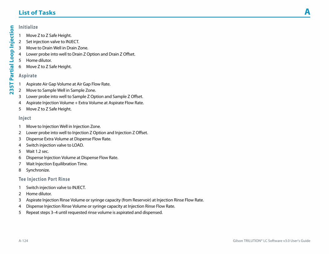
List of Tasks A
A-124 Gilson TRILUTION® LC Software v3.0 User’s Guide
235T
Par
tial
Loo
p In
ject
ion Initialize
1 Move Z to Z Safe Height.2 Set injection valve to INJECT.3 Move to Drain Well in Drain Zone.4 Lower probe into well to Drain Z Option and Drain Z Offset.5 Home dilutor.6 Move Z to Z Safe Height.
Aspirate1 Aspirate Air Gap Volume at Air Gap Flow Rate.2 Move to Sample Well in Sample Zone.3 Lower probe into well to Sample Z Option and Sample Z Offset.4 Aspirate Injection Volume + Extra Volume at Aspirate Flow Rate.5 Move Z to Z Safe Height.
Inject1 Move to Injection Well in Injection Zone.2 Lower probe into well to Injection Z Option and Injection Z Offset.3 Dispense Extra Volume at Dispense Flow Rate.4 Switch injection valve to LOAD.5 Wait 1.2 sec.6 Dispense Injection Volume at Dispense Flow Rate.7 Wait Injection Equilibration Time.8 Synchronize.
Tee Injection Port Rinse1 Switch injection valve to INJECT.2 Home dilutor.3 Aspirate Injection Rinse Volume or syringe capacity (from Reservoir) at Injection Rinse Flow Rate.4 Dispense Injection Rinse Volume or syringe capacity at Injection Rinse Flow Rate.5 Repeat steps 3–4 until requested rinse volume is aspirated and dispensed.

Gilson TRILUTION® LC Software v3.0 User’s Guide A-125
List of Tasks A235T Partial Loop Injection
Above Seal Rinse1 Raise probe to 5 mm above bottom of injection port.2 Aspirate Above Seal Rinse Volume or syringe capacity (from Reservoir) at Injection Rinse Flow Rate.3 Dispense Above Seal Rinse Volume or syringe capacity at Injection Rinse Flow Rate.4 Repeat steps 2-3 until requested rinse volume is aspirated and dispensed.5 Move Z to Z Safe Height.
Outside Rinse1 Move Z to Z Safe Height.2 Move to Outside Rinse Well in Outside Rinse Zone.3 Lower probe into well to Outside Rinse Z Option and Outside Rinse Z Offset.4 Home dilutor.5 Aspirate Outside Rinse Volume or syringe capacity (from Reservoir) at Outside Rinse Flow Rate.6 Dispense Outside Rinse Volume or syringe capacity at Outside Rinse Flow Rate.7 Repeat steps 5–6 until requested rinse volume is aspirated and dispensed.8 Move Z to Z Safe Height.

List of Tasks A
A-126 Gilson TRILUTION® LC Software v3.0 User’s Guide
235T
Tot
al L
oop
Inje
ctio
n 235T Total Loop InjectionThis task performs a total loop injection on a 235 Autoinjector with tee injection port.
For more information about the properties on each tab, refer to:
235T Total Loop Injection Properties - Main
235T Total Loop Injection Properties - Advanced
235T Total Loop Injection Properties - Rinsing
235T Total Loop Injection - Sequence of Steps
235T Total Loop Injection Properties - Main
Property Name Description Default Value
Autoinjector The autoinjector that the task will affect. Liquid Handler
Sample Zone The zone from which the Injection Volume and Extra Volume are aspirated. Sample Zone
Sample Well Enter the well number in the Sample Zone. 0
Injection Zone The zone to which the Extra Volume, Injection Volume, and Push Volume are dispensed. Injection Zone
235T Total Loop Injection Properties - Main (Page 1 of 2)

Gilson TRILUTION® LC Software v3.0 User’s Guide A-127
List of Tasks A235T Total Loop Injection
Injection Well Enter the well number in the Injection Zone. 1
Air Gap Volume The quantity of an air gap. 6 μL
Extra Volume An additional volume to the first volume aspirated. It ensures that the actual volume of liquid to be transferred is not contaminated, and acts as an extra buffer between the air gap/reservoir solvent and the Injection Volume. 6 μL
Loop Volume Overfill A factor to multiply the Loop Volume by that determines the injection volume. Injection Volume = Loop Volume Overfill x Loop Volume. 5
Loop Volume The capacity of the installed sample loop. 0 μL
235T Total Loop Injection Properties - Advanced
Property Name Description Default Value
Aspirate Flow Rate The speed at which liquid volumes move into the probe. 0.5 mL/min
Dispense Flow Rate The speed at which liquid volumes move out of the probe. 0.3 mL/min
Air Gap Flow Rate The speed at which the Air Gap Volume moves into the probe. 0.3 mL/min
Injection Equilibration Time Time the program waits after loading the Extra Volume, Injection Volume, and Push Volume in the sample loop. 0.05 min
Sample Z Option
One of six defined reference points used when aspirating the Injection Volume and Extra Volume from the bed:Auto Calculate: Places probe into well and at the liquid level using initial volume from the sample list and well dimensions from the bed layout; accepts a positive (+) or negative (-) value for the Sample Z Offset.Absolute Value: Moves the probe to the Z-value entered; if 0 is entered, probe will move to the bed bottom (no safety factor incorporated).Tube Bottom: Moves the probe to the well bottom as defined by the bed layout; accepts only positive Sample Z Offset value to move up from the bottom.Top: Moves probe to the top of their Z-travel range; accepts only a negative (-) value for the Sample Z Offset.Tube Top: Moves the probe to the top of the well as defined by the bed layout; accepts a positive (+) or negative (-) value for the Sample Z Offset.Z Adjust: Moves the probe from the current position up (positive value) or down (negative value).
Tube Bottom
Sample Z Offset The distance up (when a positive number is entered) or down (when a negative number is entered) from a reference point defined by the Sample Z Option used when aspirating the Injection Volume and Extra Volume from the bed. 2 mm
Injection Z Option
One of six defined reference points used when injecting the Injection Volume and Extra Volume:Auto Calculate: Places probe into well and at the liquid level using initial volume from the sample list and well dimensions from the bed layout; accepts a positive (+) or negative (-) value for the Injection Z Offset.Absolute Value: Moves the probe to the Z-value entered; if 0 is entered, probe will move to the bed bottom (no safety factor incorporated).Tube Bottom: Moves the probe to the well bottom as defined by the bed layout; accepts only positive Injection Z Offset value to move up from the bottom.Top: Moves probe to the top of their Z-travel range; accepts only a negative (-) value for the Injection Z Offset.Tube Top: Moves the probe to the top of the well as defined by the bed layout; accepts a positive (+) or negative (-) value for the Injection Z Offset.Z Adjust: Moves the probe from the current position up (positive value) or down (negative value).
Tube Bottom
Injection Z Offset The distance up (when a positive number is entered) or down (when a negative number is entered) from a reference point defined by the Injection Z Option used when injecting the Injection Volume and Extra Volume. 0 mm
235T Total Loop Injection Properties - Advanced
235T Total Loop Injection Properties - Main (Continued)
Property Name Description Default Value
235T Total Loop Injection Properties - Main (Page 2 of 2)

List of Tasks A
A-128 Gilson TRILUTION® LC Software v3.0 User’s Guide
235T
Tot
al L
oop
Inje
ctio
n
235T Total Loop Injection Properties - Rinsing
Property Name Description Default Value
Drain Zone The zone in which the dilutor is homed. Inside Rinse
Drain Well Enter the well number in the Drain Zone. 1
Drain Z Option
One of six defined reference points used when purging to the drain:Auto Calculate: Places probe into well and at the liquid level using initial volume from the sample list and well dimensions from the bed layout; accepts a positive (+) or negative (-) value for the Drain Z Offset.Absolute Value: Moves the probe to the Z-value entered; if 0 is entered for the Drain Z Offset, probe will move to the bed bottom (no safety factor incorporated).Tube Bottom: Moves the probe to the well bottom as defined by the bed layout; accepts only positive Drain Z Offset values to move up from the bottom.Top: Moves probe to the top of their Z-travel range; accepts only a negative (-) value for the Drain Z Offset.Tube Top: Moves the probe to the top of the well as defined by the bed layout; accepts a positive (+) or negative (-) value for the Drain Z Offset.Z Adjust: Moves the probe from the current position up (positive value) or down (negative value).
Tube Bottom
Drain Z Offset The distance up (when a positive number is entered) or down (when a negative number is entered) from a reference point defined by the Drain Z Option for purging to the drain. 2 mm
Injection Rinse Volume The quantity of liquid used to rinse the injection port at Injection Well in Injection Zone. 250 μL
Above Seal Rinse Volume The quantity of liquid dispensed above the seal. 250 μL
Injection Rinse Flow Rate The speed at which the Injection Rinse Volume moves out of the probe and into the injection port. 3.3 mL/min
Outside Rinse Zone The zone to which the Outside Rinse Volume is delivered. Outside Rinse
Outside Rinse Well Enter the well number in the Outside Rinse Zone. 1
Outside Rinse Volume The quantity of liquid used to rinse the outside of the probe. 300 μL
Outside Rinse Flow Rate The speed at which the Outside Rinse Volume moves out of the probe and into the outside rinse position in the rinse station. 3.3 mL/min
Outside Rinse Z Option
One of six defined reference points used when performing the outside rinse:Auto Calculate: Places probe into well and at the liquid level using initial volume from the sample list and well dimensions from the bed layout; accepts a positive (+) or negative (-) value for the Outside Rinse Z Offset.Absolute Value: Moves the probe to the Z-value entered; if 0 is entered, probe will move to the bed bottom (no safety factor incorporated).Tube Bottom: Moves the probe to the well bottom as defined by the bed layout; accepts only positive Outside Rinse Z Offset values to move up from the bottom.Top: Moves probe to the top of their Z-travel range; accepts only a negative (-) value for the Outside Rinse Z Offset.Tube Top: Moves the probe to the top of the well as defined by the bed layout; accepts a positive (+) or negative (-) value for the Outside Rinse Z Offset.Z Adjust: Moves the probe from the current position up (positive value) or down (negative value).
Tube Bottom
Outside Rinse Z Offset The distance up (when a positive number is entered) or down (when a negative number is entered) from a reference point defined by the Outside Rinse Z Option for rinsing the probe at the outside rinse position in the rinse station. 2 mm
235T Total Loop Injection Properties - Rinsing

Gilson TRILUTION® LC Software v3.0 User’s Guide A-129
List of Tasks A235T Total Loop Injection
235T Total Loop Injection - Sequence of StepsThe following is an overview for the sequence of steps.
1 Initialize2 Aspirate3 Inject4 Tee Injection Port Rinse5 Above Seal Rinse6 Outside Rinse
Initialize1 Move Z to Z Safe Height.2 Set injection valve to INJECT.3 Move to Drain Well in Drain Zone.4 Lower probe into well to Drain Z Option and Drain Z Offset.5 Home dilutor.6 Move Z to Z Safe Height.
Aspirate1 Aspirate Air Gap Volume at Air Gap Flow Rate.2 Move to Sample Well in Sample Zone.3 Lower probe into well to Sample Z Option and Sample Z Offset.4 Aspirate the injection volume (injection volume = Loop Overfill x Loop Volume) + Extra Volume at Aspirate Flow Rate.5 Move Z to Z Safe Height.
Inject1 Move to Injection Well in Injection Zone.2 Lower probe into well to Injection Z Option and Injection Z Offset.3 Switch injection valve to LOAD.4 Wait 1.2 sec.5 Dispense the injection volume (injection volume = Loop Overfill x Loop Volume) at Dispense Flow Rate.6 Wait Injection Equilibration Time.7 Synchronize.
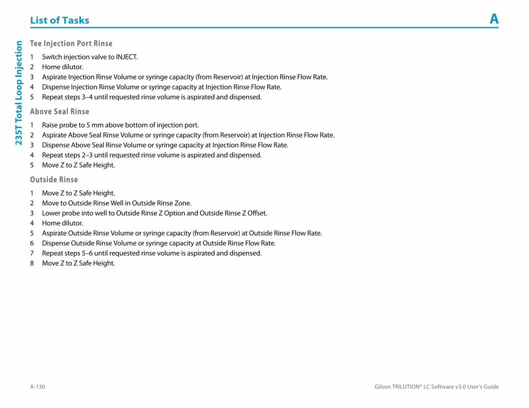
List of Tasks A
A-130 Gilson TRILUTION® LC Software v3.0 User’s Guide
235T
Tot
al L
oop
Inje
ctio
n Tee Injection Port Rinse1 Switch injection valve to INJECT.2 Home dilutor.3 Aspirate Injection Rinse Volume or syringe capacity (from Reservoir) at Injection Rinse Flow Rate.4 Dispense Injection Rinse Volume or syringe capacity at Injection Rinse Flow Rate.5 Repeat steps 3–4 until requested rinse volume is aspirated and dispensed.
Above Seal Rinse1 Raise probe to 5 mm above bottom of injection port.2 Aspirate Above Seal Rinse Volume or syringe capacity (from Reservoir) at Injection Rinse Flow Rate.3 Dispense Above Seal Rinse Volume or syringe capacity at Injection Rinse Flow Rate.4 Repeat steps 2–3 until requested rinse volume is aspirated and dispensed.5 Move Z to Z Safe Height.
Outside Rinse1 Move Z to Z Safe Height.2 Move to Outside Rinse Well in Outside Rinse Zone.3 Lower probe into well to Outside Rinse Z Option and Outside Rinse Z Offset.4 Home dilutor.5 Aspirate Outside Rinse Volume or syringe capacity (from Reservoir) at Outside Rinse Flow Rate.6 Dispense Outside Rinse Volume or syringe capacity at Outside Rinse Flow Rate.7 Repeat steps 5–6 until requested rinse volume is aspirated and dispensed.8 Move Z to Z Safe Height.

Gilson TRILUTION® LC Software v3.0 User’s Guide A-131
List of Tasks A506C
Autozero
Channel
506C Autozero ChannelThis task sets the output trace of the specified channels on the System Interface to zero.
For more information about the properties on each tab, refer to:
506C Autozero Channel Properties
506C Autozero Channel Properties
Property Name Description Default Value
System Interface The System Interface that the task will affect. Contact
Channel Enter the letter or letters that correspond to the output channel to act on for the system interface selected. ABCD
506C Autozero Channel Properties
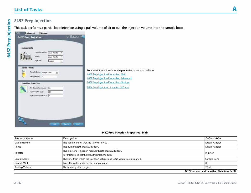
List of Tasks A
A-132 Gilson TRILUTION® LC Software v3.0 User’s Guide
845Z
Pre
p In
ject
ion 845Z Prep Injection
This task performs a partial loop injection using a pull volume of air to pull the injection volume into the sample loop.
For more information about the properties on each tab, refer to:
845Z Prep Injection Properties - Main
845Z Prep Injection Properties - Advanced
845Z Prep Injection Properties - Rinsing
845Z Prep Injection - Sequence of Steps
845Z Prep Injection Properties - Main
Property Name Description Default Value
Liquid Handler The liquid handler that the task will affect. Liquid Handler
Pump The pump that the task will affect. Liquid Handler
InjectorThe injector or injection module that the task will affect.
For this task, select the 845Z Injection Module.Injector
Sample Zone The zone from which the Injection Volume and Extra Volume are aspirated. Sample Zone
Sample Well Enter the well number in the Sample Zone. 0
Air Gap Volume The quantity of an air gap. 20 μL
845Z Prep Injection Properties - Main (Page 1 of 2)

Gilson TRILUTION® LC Software v3.0 User’s Guide A-133
List of Tasks A845Z Prep Injection
Pull Volume A volume of air used to pull the injection volume into the sample loop.
200 μL
Note: This default was determined using a 125 mm Z arm and a 0.8 mm ID probe.
Injection Volume The volume of sample to be injected. 0 μL
845Z Prep Injection Properties - Advanced
Property Name Description Default Value
Aspirate Flow Rate The speed at which the Injection Volume and the Pull Volume moves into the probe. 4 mL/min
Air Gap Flow Rate The speed at which the Air Gap Volume moves into the probe. 1 mL/min
Injection Equilibration Time Time the program waits after loading the Extra Volume, Injection Volume, and Push Volume in the sample loop. 0.05 min
Sample Z Option
One of six defined reference points used when aspirating the Injection Volume from the bed:Auto Calculate: Places probe into well and at the liquid level using initial volume from the sample list and well dimensions from the bed layout; accepts a positive (+) or negative (-) value for the Sample Z Offset.Absolute Value: Moves the probe to the Z-value entered; if 0 is entered, probe will move to the bed bottom (no safety factor incorporated).Tube Bottom: Moves the probe to the well bottom as defined by the bed layout; accepts only positive Sample Z Offset value to move up from the bottom.Top: Moves probe to the top of their Z-travel range; accepts only a negative (-) value for the Sample Z Offset.Tube Top: Moves the probe to the top of the well as defined by the bed layout; accepts a positive (+) or negative (-) value for the Sample Z Offset.Z Adjust: Moves the probe from the current position up (positive value) or down (negative value).
Tube Bottom
Sample Z Offset The distance up (when a positive number is entered) or down (when a negative number is entered) from a reference point defined by the Sample Z Option used when aspirating the Injection Volume from the bed. 2 mm
Liquid Level FollowingWhen selected, the probe will follow the liquid down as it is aspirated from the Sample Zone. The Sample Z Option must be set to AUTO CALCULATE and initial volumes must be set in the sample list to use this option.
When cleared, the probe will not follow the liquid down as it is aspirated from the Sample Zone.Cleared
845Z Prep Injection Properties - Advanced
845Z Prep Injection Properties - Rinsing For information about rinse positions, refer to Appendix B, Rinse Locations.
Property Name Description Default Value
Inside Rinse Zone The zone to which the Inside Rinse Volume is delivered. Inside Rinse
Inside Rinse Well Enter the well number in the Inside Rinse Zone. 1
Inside Rinse Volume The quantity of liquid used to rinse the inside of the probe. 500 μL
Inside Rinse Flow Rate The speed at which the Inside Rinse Volume moves out of the probe and into the inside rinse position in the rinse station. 10 mL/min
845Z Prep Injection Properties - Rinsing (Page 1 of 2)
845Z Prep Injection Properties - Main (Continued)
Property Name Description Default Value
845Z Prep Injection Properties - Main (Page 2 of 2)

List of Tasks A
A-134 Gilson TRILUTION® LC Software v3.0 User’s Guide
845Z
Pre
p In
ject
ion
Inside Rinse Z Option
One of six defined reference points used when performing the inside rinse:Auto Calculate: Places probe into well and at the liquid level using initial volume from the sample list and well dimensions from the bed layout; accepts a positive (+) or negative (-) value for the Inside Rinse Z Offset.Absolute Value: Moves the probe to the Z-value entered; if 0 is entered, probe will move to the bed bottom (no safety factor incorporated).Tube Bottom: Moves the probe to the well bottom as defined by the bed layout; accepts only positive Inside Rinse Z Offset values to move up from the bottom.Top: Moves probe to the top of their Z-travel range; accepts only a negative (-) value for the Inside Rinse Z Offset.Tube Top: Moves the probe to the top of the well as defined by the bed layout; accepts a positive (+) or negative (-) value for the Inside Rinse Z Offset.Z Adjust: Moves the probe from the current position up (positive value) or down (negative value).
Tube Bottom
Inside Rinse Z Offset The distance up (when a positive number is entered) or down (when a negative number is entered) from a reference point defined by the Inside Rinse Z Option for rinsing the probe at the inside rinse position in the rinse station. 2 mm
Outside Rinse Zone The zone to which the Outside Rinse Volume is delivered. Outside Rinse
Outside Rinse Well Enter the well number in the Outside Rinse Zone. 1
Outside Rinse Volume The quantity of liquid used to rinse the outside of the probe. 500 μL
Outside Rinse Flow Rate The speed at which the Outside Rinse Volume moves out of the probe and into the outside rinse position in the rinse station. 10 mL/min
Outside Rinse Z Option
One of six defined reference points used when performing the outside rinse:Auto Calculate: Places probe into well and at the liquid level using initial volume from the sample list and well dimensions from the bed layout; accepts a positive (+) or negative (-) value for the Outside Rinse Z Offset.Absolute Value: Moves the probe to the Z-value entered; if 0 is entered, probe will move to the bed bottom (no safety factor incorporated).Tube Bottom: Moves the probe to the well bottom as defined by the bed layout; accepts only positive Outside Rinse Z Offset values to move up from the bottom.Top: Moves probe to the top of their Z-travel range; accepts only a negative (-) value for the Outside Rinse Z Offset.Tube Top: Moves the probe to the top of the well as defined by the bed layout; accepts a positive (+) or negative (-) value for the Outside Rinse Z Offset.Z Adjust: Moves the probe from the current position up (positive value) or down (negative value).
Tube Bottom
Outside Rinse Z Offset The distance up (when a positive number is entered) or down (when a negative number is entered) from a reference point defined by the Outside Rinse Z Option for rinsing the probe at the outside rinse position in the rinse station. 2 mm
845Z Prep Injection Properties - Rinsing (Continued)For information about rinse positions, refer to Appendix B, Rinse Locations.
Property Name Description Default Value
845Z Prep Injection Properties - Rinsing (Page 2 of 2)
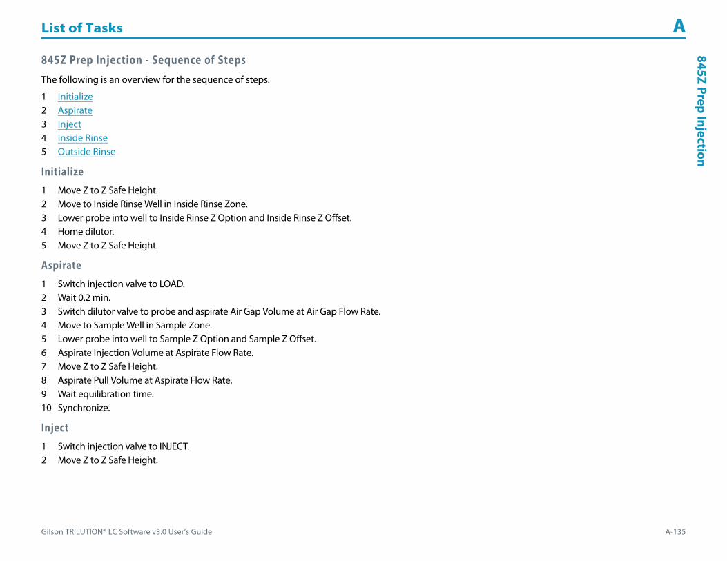
Gilson TRILUTION® LC Software v3.0 User’s Guide A-135
List of Tasks A845Z Prep Injection
845Z Prep Injection - Sequence of StepsThe following is an overview for the sequence of steps.
1 Initialize2 Aspirate3 Inject4 Inside Rinse5 Outside Rinse
Initialize1 Move Z to Z Safe Height.2 Move to Inside Rinse Well in Inside Rinse Zone.3 Lower probe into well to Inside Rinse Z Option and Inside Rinse Z Offset.4 Home dilutor.5 Move Z to Z Safe Height.
Aspirate1 Switch injection valve to LOAD.2 Wait 0.2 min.3 Switch dilutor valve to probe and aspirate Air Gap Volume at Air Gap Flow Rate.4 Move to Sample Well in Sample Zone.5 Lower probe into well to Sample Z Option and Sample Z Offset.6 Aspirate Injection Volume at Aspirate Flow Rate.7 Move Z to Z Safe Height.8 Aspirate Pull Volume at Aspirate Flow Rate.9 Wait equilibration time.10 Synchronize.
Inject1 Switch injection valve to INJECT.2 Move Z to Z Safe Height.

List of Tasks A
A-136 Gilson TRILUTION® LC Software v3.0 User’s Guide
845Z
Pre
p In
ject
ion Inside Rinse
1 Move to Inside Rinse Well in Inside Rinse Zone.2 Lower probe into well to Inside Rinse Z Option and Inside Rinse Z Offset.3 Home dilutor.4 Switch dilutor valve to reservoir.5 Aspirate Inside Rinse Volume or syringe capacity at Inside Rinse Flow Rate.6 Switch dilutor valve to probe.7 Dispense Inside Rinse Volume or syringe capacity at Inside Rinse Flow Rate.8 Repeat steps 4–7 until requested rinse volume is aspirated and dispensed.9 Move Z to Z Safe Height.
Outside Rinse1 Move to Outside Rinse Well in Outside Rinse Zone.2 Lower probe into well to Outside Rinse Z Option and Outside Rinse Z Offset.3 Home dilutor.4 Switch dilutor valve to reservoir.5 Aspirate Outside Rinse Volume or syringe capacity at Outside Rinse Flow Rate.6 Switch dilutor valve to probe.7 Dispense Outside Rinse Volume or syringe capacity at Outside Rinse Flow Rate.8 Repeat steps 4–7 until requested rinse volume is aspirated and dispensed.
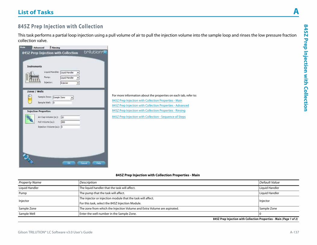
Gilson TRILUTION® LC Software v3.0 User’s Guide A-137
List of Tasks A845Z Prep Injection w
ith Collection
845Z Prep Injection with CollectionThis task performs a partial loop injection using a pull volume of air to pull the injection volume into the sample loop and rinses the low pressure fraction collection valve.
For more information about the properties on each tab, refer to:
845Z Prep Injection with Collection Properties - Main
845Z Prep Injection with Collection Properties - Advanced
845Z Prep Injection with Collection Properties - Rinsing
845Z Prep Injection with Collection - Sequence of Steps
845Z Prep Injection with Collection Properties - Main
Property Name Description Default Value
Liquid Handler The liquid handler that the task will affect. Liquid Handler
Pump The pump that the task will affect. Liquid Handler
InjectorThe injector or injection module that the task will affect.
For this task, select the 845Z Injection Module.Injector
Sample Zone The zone from which the Injection Volume and Extra Volume are aspirated. Sample Zone
Sample Well Enter the well number in the Sample Zone. 0
845Z Prep Injection with Collection Properties - Main (Page 1 of 2)
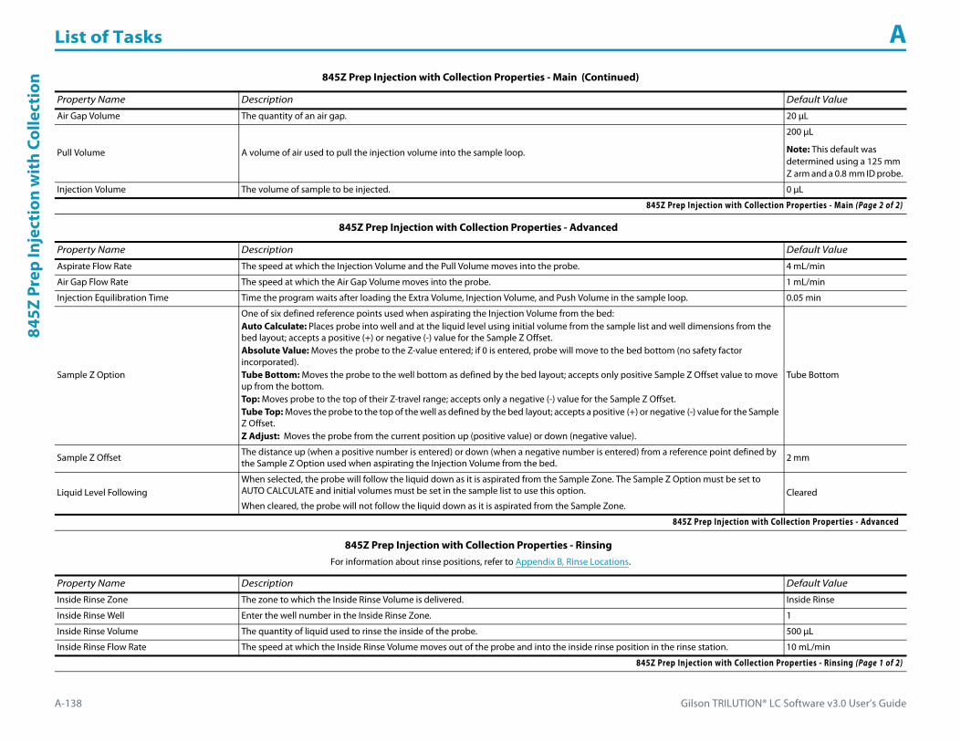
List of Tasks A
A-138 Gilson TRILUTION® LC Software v3.0 User’s Guide
845Z
Pre
p In
ject
ion
wit
h Co
llect
ion
Air Gap Volume The quantity of an air gap. 20 μL
Pull Volume A volume of air used to pull the injection volume into the sample loop.
200 μL
Note: This default was determined using a 125 mm Z arm and a 0.8 mm ID probe.
Injection Volume The volume of sample to be injected. 0 μL
845Z Prep Injection with Collection Properties - Advanced
Property Name Description Default Value
Aspirate Flow Rate The speed at which the Injection Volume and the Pull Volume moves into the probe. 4 mL/min
Air Gap Flow Rate The speed at which the Air Gap Volume moves into the probe. 1 mL/min
Injection Equilibration Time Time the program waits after loading the Extra Volume, Injection Volume, and Push Volume in the sample loop. 0.05 min
Sample Z Option
One of six defined reference points used when aspirating the Injection Volume from the bed:Auto Calculate: Places probe into well and at the liquid level using initial volume from the sample list and well dimensions from the bed layout; accepts a positive (+) or negative (-) value for the Sample Z Offset.Absolute Value: Moves the probe to the Z-value entered; if 0 is entered, probe will move to the bed bottom (no safety factor incorporated).Tube Bottom: Moves the probe to the well bottom as defined by the bed layout; accepts only positive Sample Z Offset value to move up from the bottom.Top: Moves probe to the top of their Z-travel range; accepts only a negative (-) value for the Sample Z Offset.Tube Top: Moves the probe to the top of the well as defined by the bed layout; accepts a positive (+) or negative (-) value for the Sample Z Offset.Z Adjust: Moves the probe from the current position up (positive value) or down (negative value).
Tube Bottom
Sample Z Offset The distance up (when a positive number is entered) or down (when a negative number is entered) from a reference point defined by the Sample Z Option used when aspirating the Injection Volume from the bed. 2 mm
Liquid Level FollowingWhen selected, the probe will follow the liquid down as it is aspirated from the Sample Zone. The Sample Z Option must be set to AUTO CALCULATE and initial volumes must be set in the sample list to use this option.
When cleared, the probe will not follow the liquid down as it is aspirated from the Sample Zone.Cleared
845Z Prep Injection with Collection Properties - Advanced
845Z Prep Injection with Collection Properties - Rinsing For information about rinse positions, refer to Appendix B, Rinse Locations.
Property Name Description Default Value
Inside Rinse Zone The zone to which the Inside Rinse Volume is delivered. Inside Rinse
Inside Rinse Well Enter the well number in the Inside Rinse Zone. 1
Inside Rinse Volume The quantity of liquid used to rinse the inside of the probe. 500 μL
Inside Rinse Flow Rate The speed at which the Inside Rinse Volume moves out of the probe and into the inside rinse position in the rinse station. 10 mL/min
845Z Prep Injection with Collection Properties - Rinsing (Page 1 of 2)
845Z Prep Injection with Collection Properties - Main (Continued)
Property Name Description Default Value
845Z Prep Injection with Collection Properties - Main (Page 2 of 2)

Gilson TRILUTION® LC Software v3.0 User’s Guide A-139
List of Tasks A845Z Prep Injection w
ith Collection
Inside Rinse Z Option
One of six defined reference points used when performing the inside rinse:Auto Calculate: Places probe into well and at the liquid level using initial volume from the sample list and well dimensions from the bed layout; accepts a positive (+) or negative (-) value for the Inside Rinse Z Offset.Absolute Value: Moves the probe to the Z-value entered; if 0 is entered, probe will move to the bed bottom (no safety factor incorporated).Tube Bottom: Moves the probe to the well bottom as defined by the bed layout; accepts only positive Inside Rinse Z Offset values to move up from the bottom.Top: Moves probe to the top of their Z-travel range; accepts only a negative (-) value for the Inside Rinse Z Offset.Tube Top: Moves the probe to the top of the well as defined by the bed layout; accepts a positive (+) or negative (-) value for the Inside Rinse Z Offset.Z Adjust: Moves the probe from the current position up (positive value) or down (negative value).
Tube Bottom
Inside Rinse Z Offset The distance up (when a positive number is entered) or down (when a negative number is entered) from a reference point defined by the Inside Rinse Z Option for rinsing the probe at the inside rinse position in the rinse station. 2 mm
Outside Rinse Zone The zone to which the Outside Rinse Volume is delivered. Outside Rinse
Outside Rinse Well Enter the well number in the Outside Rinse Zone. 1
Outside Rinse Volume The quantity of liquid used to rinse the outside of the probe. 500 μL
Outside Rinse Flow Rate The speed at which the Outside Rinse Volume moves out of the probe and into the outside rinse position in the rinse station. 10 mL/min
Outside Rinse Z Option
One of six defined reference points used when performing the outside rinse:Auto Calculate: Places probe into well and at the liquid level using initial volume from the sample list and well dimensions from the bed layout; accepts a positive (+) or negative (-) value for the Outside Rinse Z Offset.Absolute Value: Moves the probe to the Z-value entered; if 0 is entered, probe will move to the bed bottom (no safety factor incorporated).Tube Bottom: Moves the probe to the well bottom as defined by the bed layout; accepts only positive Outside Rinse Z Offset values to move up from the bottom.Top: Moves probe to the top of their Z-travel range; accepts only a negative (-) value for the Outside Rinse Z Offset.Tube Top: Moves the probe to the top of the well as defined by the bed layout; accepts a positive (+) or negative (-) value for the Outside Rinse Z Offset.Z Adjust: Moves the probe from the current position up (positive value) or down (negative value).
Tube Bottom
Outside Rinse Z Offset The distance up (when a positive number is entered) or down (when a negative number is entered) from a reference point defined by the Outside Rinse Z Option for rinsing the probe at the outside rinse position in the rinse station. 2 mm
845Z Prep Injection with Collection Properties - Rinsing (Continued)For information about rinse positions, refer to Appendix B, Rinse Locations.
Property Name Description Default Value
845Z Prep Injection with Collection Properties - Rinsing (Page 2 of 2)

List of Tasks A
A-140 Gilson TRILUTION® LC Software v3.0 User’s Guide
845Z
Pre
p In
ject
ion
wit
h Co
llect
ion 845Z Prep Injection with Collection - Sequence of Steps
The following is an overview for the sequence of steps.
1 Initialize2 Aspirate3 Inject4 Inside Rinse5 Outside Rinse
Initialize1 Move Z to Z Safe Height.2 Move to Inside Rinse Well in Inside Rinse Zone.3 Lower probe into well to Inside Rinse Z Option and Inside Rinse Z Offset.4 Home dilutor.5 Move Z to Z Safe Height.6 Switch low pressure fraction collection valve to COLLECT for 2 seconds.7 Switch injection valve to LOAD.8 Wait 0.2 min.
Aspirate1 Switch dilutor valve to probe and aspirate Air Gap Volume at Air Gap Flow Rate.2 Move to Sample Well in Sample Zone.3 Lower probe into well to Sample Z Option and Sample Z Offset.4 Aspirate Injection Volume at Aspirate Flow Rate.5 Move Z to Z Safe Height.6 Aspirate Pull Volume at Aspirate Flow Rate.7 Wait equilibration time.8 Synchronize.
Inject1 Switch injection valve to INJECT.2 Move Z to Z Safe Height.

Gilson TRILUTION® LC Software v3.0 User’s Guide A-141
List of Tasks A845Z Prep Injection w
ith Collection
Inside Rinse1 Move to Inside Rinse Well in Inside Rinse Zone.2 Lower probe into well to Inside Rinse Z Option and Inside Rinse Z Offset.3 Home dilutor.4 Switch dilutor valve to reservoir.5 Aspirate Inside Rinse Volume or syringe capacity at Inside Rinse Flow Rate.6 Switch dilutor valve to probe.7 Dispense Inside Rinse Volume or syringe capacity at Inside Rinse Flow Rate.8 Repeat steps 4–7 until requested rinse volume is aspirated and dispensed.9 Move Z to Z Safe Height.
Outside Rinse1 Move to Outside Rinse Well in Outside Rinse Zone.2 Lower probe into well to Outside Rinse Z Option and Outside Rinse Z Offset.3 Home dilutor.4 Switch dilutor valve to reservoir.5 Aspirate Outside Rinse Volume or syringe capacity at Outside Rinse Flow Rate.6 Switch dilutor valve to probe.7 Dispense Outside Rinse Volume or syringe capacity at Outside Rinse Flow Rate.8 Repeat steps 4–7 until requested rinse volume is aspirated and dispensed.

List of Tasks A
A-142 Gilson TRILUTION® LC Software v3.0 User’s Guide
Add
Dilu
ent Add Diluent
This task aspirates the specified amount of liquid (Diluent Source) from the reservoir or the probe and then dispenses to the wells of the sample zone and then mixes with liquid or air.
For more information about the properties on each tab, refer to:
Add Diluent Properties - Main
Add Diluent Properties - Advanced
Add Diluent Properties - Mixing
Add Diluent Properties - Rinsing
Add Diluent - Sequence of Steps
Add Diluent Properties - Main
Property Name Description Default Value
Liquid Handler The liquid handler that the task will affect. Liquid Handler
Pump The pump that the task will affect. Pump
Diluent Source Select Reservoir or Tray. Reservoir
ReservoirSample Zone
The zone to which the Diluent Volume is delivered. Sample Zone
Add Diluent Properties - Main (Page 1 of 2)

Gilson TRILUTION® LC Software v3.0 User’s Guide A-143
List of Tasks AA
dd Diluent
ReservoirSample Well
Enter the well number in the Sample Zone. 0
TrayDiluent Zone
When Tray is selected; the zone from which the Diluent Volume is aspirated. Sample Zone
TrayDiluent Well
When Tray is selected; enter the well number in the Diluent Zone. 0
TraySample Zone
The zone to which the Diluent Volume is delivered. Sample Zone
TraySample Well
Enter the well number in the Sample Zone. 0
Air Gap Volume The quantity of an air gap. 6 μL
Diluent Volume The quantity of liquid used to dilute the sample volume in the Sample Well in the Sample Zone. 0 μL
Add Diluent Properties - Advanced
Property Name Description Default Value
Aspirate Flow Rate The speed at which liquid volumes move into the probe. 1.5 mL/min
Dispense Flow Rate The speed at which liquid volumes move out of the probe. 3 mL/min
Air Gap Flow Rate The speed at which the Air Gap Volume moves into the probe. 0.3 mL/min
Aspirate Z Option
One of six defined reference points used when aspirating the Diluent Volume from the bed:Auto Calculate: Places probe into well and at the liquid level using initial volume from the sample list and well dimensions from the bed layout; accepts a positive (+) or negative (-) value for the Aspirate Z Offset.Absolute Value: Moves the probe to the Z-value entered; if 0 is entered, probe will move to the bed bottom (no safety factor incorporated).Tube Bottom: Moves the probe to the well bottom as defined by the bed layout; accepts only positive Aspirate Z Offset value to move up from the bottom.Top: Moves probe to the top of their Z-travel range; accepts only a negative (-) value for the Aspirate Z Offset.Tube Top: Moves the probe to the top of the well as defined by the bed layout; accepts a positive (+) or negative (-) value for the Aspirate Z Offset.Z Adjust: Moves the probe from the current position up (positive value) or down (negative value).
Tube Bottom
Aspirate Z Offset When selected the distance up (when a positive number is entered) or down (when a negative number is entered) from a reference point defined by the Aspirate Z Option used when aspirating the Diluent Volume from the bed. 2 mm
Aspirate LLFWhen selected the probe will follow the liquid down as it is aspirated from the Diluent Zone. The Aspirate Z Option must be set to AUTO CALCULATE and initial volumes must be set in the sample list to use this option.
When cleared, and the probe will not follow the liquid down as it is aspirated from the Diluent Zone.Cleared
Add Diluent Properties - Advanced (Page 1 of 2)
Add Diluent Properties - Main (Continued)
Property Name Description Default Value
Add Diluent Properties - Main (Page 2 of 2)

List of Tasks A
A-144 Gilson TRILUTION® LC Software v3.0 User’s Guide
Add
Dilu
ent
Dispense Z Option
One of six defined reference points used when delivering the Diluent Volume to the bed:Auto Calculate: Places probe into well and at the liquid level using initial volume from the sample list and well dimensions from the bed layout; accepts a positive (+) or negative (-) value for the Dispense Z Offset.Absolute Value: Moves the probe to the Z-value entered; if 0 is entered, probe will move to the bed bottom (no safety factor incorporated).Tube Bottom: Moves the probe to the well bottom as defined by the bed layout; accepts only positive Dispense Z Offset value to move up from the bottom.Top: Moves probe to the top of their Z-travel range; accepts only a negative (-) value for the Dispense Z Offset.Tube Top: Moves the probe to the top of the well as defined by the bed layout; accepts a positive (+) or negative (-) value for the Dispense Z Offset.Z Adjust: Moves the probe from the current position up (positive value) or down (negative value).
Tube Bottom
Dispense Z Offset The distance up (when a positive number is entered) or down (when a negative number is entered) from a reference point defined by the Dispense Z Option used when delivering the Diluent Volume to the bed.
2 mm
Dispense LLFWhen selected the probe will follow the liquid up as it is delivered to the Sample Zone. The Dispense Z Option must be set to AUTO CALCULATE and initial volumes must be set in the sample list to use this option.
When cleared, the probe will not follow the liquid up as it is delivered to the Sample Zone.Cleared
Add Diluent Properties - Mixing
Property Name Description Default Value
Mixing Properties Select Mix with Liquid or Mix with Air to perform a mix of the Diluent Volume with the Sample Volume. Select No Mix for no mixing. No Mix
Mix with LiquidNumber of Cycles
Type the number of times the task should repeat the commands related to mixing. 2
Mix with LiquidMixing Volume
The quantity of liquid used as part of a mixing process. 0 μL
Mix with LiquidMix Aspirate Flow Rate
The speed at which volumes move into the probe during the mixing process. 1 mL/min
Mix with LiquidMix Dispense Flow Rate
The speed at which volumes move out of the probe during the mixing process. 10 mL/min
Mix with LiquidMix Aspirate Z Option
One of six defined reference points used when aspirating the Mixing Volume from the bed:Auto Calculate: Places probe into well and at the liquid level using initial volume from the sample list and well dimensions from the bed layout; accepts a positive (+) or negative (-) value for the Mix Aspirate Z Offset.Absolute Value: Moves the probe to the Z-value entered; if 0 is entered for the Mix Aspirate Z Offset, the probe will move to the bed bottom (no safety factor incorporated).Tube Bottom: Moves the probe to the well bottom as defined by the bed layout; accepts only positive Mix Aspirate Z Offset value to move up from the bottom.Top: Moves probe to the top of their Z-travel range; accepts only a negative (-) value for the Mix Aspirate Z Offset.Tube Top: Moves the probe to the top of the well as defined by the bed layout; accepts a positive (+) or negative (-) value for the Mix Aspirate Z Offset.Z Adjust: Moves the probe from the current position up (positive value) or down (negative value).
Tube Bottom
Mix with LiquidMix Aspirate Z Offset
The distance up (when a positive number is entered) or down (when a negative number is entered) from a reference point defined by the Mix Aspirate Z Option used when aspirating the Mixing Volume from the bed. 2 mm
Mix with LiquidAspirate LLF
When Tray is selected the probe will follow the liquid down as it is aspirated from the Diluent Zone. The Aspirate Z Option must be set to AUTO CALCULATE and initial volumes must be set in the sample list to use this option.
When cleared, the probe will not follow the liquid down as it is aspirated from the Diluent Zone as part of the mixing process.Cleared
Add Diluent Properties - Mixing (Page 1 of 2)
Add Diluent Properties - Advanced (Continued)
Property Name Description Default Value
Add Diluent Properties - Advanced (Page 2 of 2)
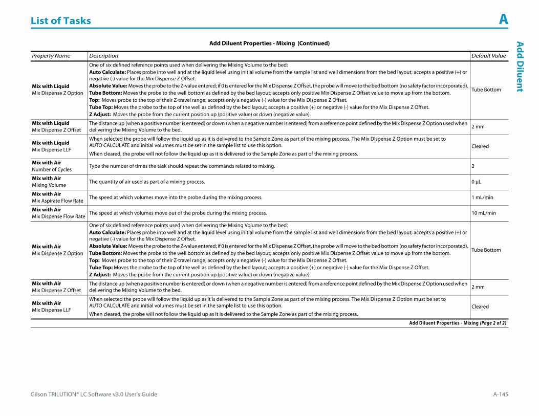
Gilson TRILUTION® LC Software v3.0 User’s Guide A-145
List of Tasks AA
dd DiluentMix with Liquid
Mix Dispense Z Option
One of six defined reference points used when delivering the Mixing Volume to the bed:Auto Calculate: Places probe into well and at the liquid level using initial volume from the sample list and well dimensions from the bed layout; accepts a positive (+) or negative (-) value for the Mix Dispense Z Offset.Absolute Value: Moves the probe to the Z-value entered; if 0 is entered for the Mix Dispense Z Offset, the probe will move to the bed bottom (no safety factor incorporated).Tube Bottom: Moves the probe to the well bottom as defined by the bed layout; accepts only positive Mix Dispense Z Offset value to move up from the bottom.Top: Moves probe to the top of their Z-travel range; accepts only a negative (-) value for the Mix Dispense Z Offset.Tube Top: Moves the probe to the top of the well as defined by the bed layout; accepts a positive (+) or negative (-) value for the Mix Dispense Z Offset.Z Adjust: Moves the probe from the current position up (positive value) or down (negative value).
Tube Bottom
Mix with LiquidMix Dispense Z Offset
The distance up (when a positive number is entered) or down (when a negative number is entered) from a reference point defined by the Mix Dispense Z Option used when delivering the Mixing Volume to the bed. 2 mm
Mix with LiquidMix Dispense LLF
When selected the probe will follow the liquid up as it is delivered to the Sample Zone as part of the mixing process. The Mix Dispense Z Option must be set to AUTO CALCULATE and initial volumes must be set in the sample list to use this option.
When cleared, the probe will not follow the liquid up as it is delivered to the Sample Zone as part of the mixing process.Cleared
Mix with AirNumber of Cycles
Type the number of times the task should repeat the commands related to mixing. 2
Mix with AirMixing Volume
The quantity of air used as part of a mixing process. 0 μL
Mix with AirMix Aspirate Flow Rate
The speed at which volumes move into the probe during the mixing process. 1 mL/min
Mix with AirMix Dispense Flow Rate
The speed at which volumes move out of the probe during the mixing process. 10 mL/min
Mix with AirMix Dispense Z Option
One of six defined reference points used when delivering the Mixing Volume to the bed:Auto Calculate: Places probe into well and at the liquid level using initial volume from the sample list and well dimensions from the bed layout; accepts a positive (+) or negative (-) value for the Mix Dispense Z Offset.Absolute Value: Moves the probe to the Z-value entered; if 0 is entered for the Mix Dispense Z Offset, the probe will move to the bed bottom (no safety factor incorporated).Tube Bottom: Moves the probe to the well bottom as defined by the bed layout; accepts only positive Mix Dispense Z Offset value to move up from the bottom.Top: Moves probe to the top of their Z-travel range; accepts only a negative (-) value for the Mix Dispense Z Offset.Tube Top: Moves the probe to the top of the well as defined by the bed layout; accepts a positive (+) or negative (-) value for the Mix Dispense Z Offset.Z Adjust: Moves the probe from the current position up (positive value) or down (negative value).
Tube Bottom
Mix with AirMix Dispense Z Offset
The distance up (when a positive number is entered) or down (when a negative number is entered) from a reference point defined by the Mix Dispense Z Option used when delivering the Mixing Volume to the bed. 2 mm
Mix with AirMix Dispense LLF
When selected the probe will follow the liquid up as it is delivered to the Sample Zone as part of the mixing process. The Mix Dispense Z Option must be set to AUTO CALCULATE and initial volumes must be set in the sample list to use this option.
When cleared, the probe will not follow the liquid up as it is delivered to the Sample Zone as part of the mixing process.Cleared
Add Diluent Properties - Mixing (Continued)
Property Name Description Default Value
Add Diluent Properties - Mixing (Page 2 of 2)

List of Tasks A
A-146 Gilson TRILUTION® LC Software v3.0 User’s Guide
Add
Dilu
ent
Add Diluent Properties - Rinsing For information about rinse positions, refer to Appendix B, Rinse Locations.
Property Name Description Default Value
Inside Rinse Zone The zone to which the Inside Rinse Volume is delivered. Inside Rinse
Inside Rinse Well Enter the well number in the Inside Rinse Zone. 1
Inside Rinse Volume The quantity of liquid used to rinse the inside of the probe. 250 μL
Inside Rinse Flow Rate The speed at which the Inside Rinse Volume moves out of the probe and into the outside rinse position in the rinse station. 10 mL/min
Inside Rinse Z Option
One of six defined reference points used when performing the inside rinse:Auto Calculate: Places probe into well and at the liquid level using initial volume from the sample list and well dimensions from the bed layout; accepts a positive (+) or negative (-) value for the Inside Rinse Z Offset.Absolute Value: Moves the probe to the Z-value entered; if 0 is entered, probe will move to the bed bottom (no safety factor incorporated).Tube Bottom: Moves the probe to the well bottom as defined by the bed layout; accepts only positive Inside Rinse Z Offset values to move up from the bottom.Top: Moves probe to the top of their Z-travel range; accepts only a negative (-) value for the Inside Rinse Z Offset.Tube Top: Moves the probe to the top of the well as defined by the bed layout; accepts a positive (+) or negative (-) value for the Inside Rinse Z Offset.Z Adjust: Moves the probe from the current position up (positive value) or down (negative value).
Tube Bottom
Inside Rinse Z Offset The distance up (when a positive number is entered) or down (when a negative number is entered) from a reference point defined by the Outside Rinse Z Option for rinsing the probe at the outside rinse position in the rinse station. 2 mm
Outside Rinse Zone The zone to which the Outside Rinse Volume is delivered. Outside Rinse
Outside Rinse Well Enter the well number in the Outside Rinse Zone. 1
Outside Rinse Volume The quantity of liquid used to rinse the outside of the probe. 500 μL
Outside Rinse Flow Rate The speed at which the Outside Rinse Volume moves out of the probe and into the outside rinse position in the rinse station. 10 mL/min
Outside Rinse Z Option
One of six defined reference points used when performing the outside rinse:Auto Calculate: Places probe into well and at the liquid level using initial volume from the sample list and well dimensions from the bed layout; accepts a positive (+) or negative (-) value for the Outside Rinse Z Offset.Absolute Value: Moves the probe to the Z-value entered; if 0 is entered, probe will move to the bed bottom (no safety factor incorporated).Tube Bottom: Moves the probe to the well bottom as defined by the bed layout; accepts only positive Outside Rinse Z Offset values to move up from the bottom.Top: Moves probe to the top of their Z-travel range; accepts only a negative (-) value for the Outside Rinse Z Offset.Tube Top: Moves the probe to the top of the well as defined by the bed layout; accepts a positive (+) or negative (-) value for the Outside Rinse Z Offset.Z Adjust: Moves the probe from the current position up (positive value) or down (negative value).
Tube Bottom
Outside Rinse Z Offset The distance up (when a positive number is entered) or down (when a negative number is entered) from a reference point defined by the Outside Rinse Z Option for rinsing the probe at the outside rinse position in the rinse station. 2 mm
Add Diluent Properties - Rinsing

Gilson TRILUTION® LC Software v3.0 User’s Guide A-147
List of Tasks AA
dd Diluent
Add Diluent - Sequence of StepsThe following is an overview for the sequence of steps.
1 Aspirate2 Dispense3 Mix with Liquid (Optional)4 Mix with Air (Optional)5 Inside Rinse6 Outside Rinse
Aspirate1 Move Z to Z Safe Height.
Reservoir1 Aspirate Diluent Volume at Aspirate Flow Rate.
Probe1 Move to Diluent Well in Diluent Zone.2 Aspirate Air Gap Volume at Air Gap Flow Rate.3 Lower probe to Aspirate Z Option and Aspirate Z Offset.4 Aspirate Diluent Volume at Aspirate Flow Rate.5 Move Z to Z Safe Height.
Dispense
Reservoir1 Move to Sample Well in Sample Zone.2 Lower probe to Dispense Z Option and Dispense Z Offset.3 Dispense Diluent Volume at Dispense Flow Rate.4 Move Z to Z Safe Height.

List of Tasks A
A-148 Gilson TRILUTION® LC Software v3.0 User’s Guide
Add
Dilu
ent Probe
Air Gap Volume = 0
1 Move to Sample Well in Sample Zone.2 Lower probe to Dispense Z Option and Dispense Z Offset.3 Dispense Diluent Volume at Dispense Flow Rate.4 Move Z to Z Safe Height.
Air Gap Volume > 0
1 Move to Sample Well in Sample Zone.2 Lower probe to Dispense Z Option and Dispense Z Offset.3 Dispense Diluent Volume and 1/2 Air Gap Volume at Dispense Flow Rate.4 Move Z to Z Safe Height.5 Move to Inside Rinse Well in Inside Rinse Zone.6 Lower probe to Inside Rinse Z Option and Inside Rinse Z Offset.7 Dispense 1/2 Air Gap Volume at Inside Rinse Flow Rate.
Mix with Liquid (Optional)1 Move Z to Z Safe Height.2 Aspirate Air Gap Volume at Air Gap Flow Rate.3 Move to Sample Well in Sample Zone.4 Lower probe to Mix Aspirate Z Option and Mix Aspirate Z Offset.5 Aspirate Mixing Volume at Mix Aspirate Flow Rate.6 Lower probe to Mix Dispense Z Option and Mix Dispense Z Offset.7 Dispense Mixing Volume at Mix Dispense Flow Rate.8 Repeat steps 4–7 for Number of Cycles.9 Move Z to Z Safe Height.

Gilson TRILUTION® LC Software v3.0 User’s Guide A-149
List of Tasks AA
dd Diluent
Mix with Air (Optional)1 Move Z to Z Safe Height.2 Move to Sample Well in Sample Zone.3 Move Z to Z Safe Height.4 Aspirate Air Gap Volume at Air Gap Flow Rate (first cycle only).5 Aspirate Mixing Volume at Mix Aspirate Flow Rate.6 Lower probe to Mix Dispense Z Option and Mix Dispense Z Offset.7 Dispense Mixing Volume at Mix Dispense Flow Rate.8 Repeat steps 3–7 for Number of Cycles.9 Move Z to Z Safe Height.
No Mix1 Skip to Inside Rinse.
Inside Rinse1 Move Z to Z Safe Height.2 Move to Inside Rinse Well in Inside Rinse Zone.3 Lower probe into well to Inside Rinse Z Option and Inside Rinse Z Offset.4 Home dilutor.5 Aspirate Inside Rinse Volume or syringe capacity (from Reservoir) at Inside Rinse Flow Rate.6 Dispense Inside Rinse Volume or syringe capacity at Inside Rinse Flow Rate.7 Repeat steps 5–6 until requested rinse volume is aspirated and dispensed.8 Move Z to Z Safe Height.
Outside Rinse1 Move Z to Z Safe Height.2 Move to Outside Rinse Well in Outside Rinse Zone.3 Lower probe into well to Outside Rinse Z Option and Outside Rinse Z Offset.4 Home dilutor.5 Aspirate Outside Rinse Volume or syringe capacity (from Reservoir) at Outside Rinse Flow Rate.6 Dispense Outside Rinse Volume or syringe capacity at Outside Rinse Flow Rate.7 Repeat steps 5–6 until requested rinse volume is aspirated and dispensed.8 Move Z to Z Safe Height.

List of Tasks A
A-150 Gilson TRILUTION® LC Software v3.0 User’s Guide
Asp
irat
e AspirateThis task aspirates an air gap or the specified volume of liquid (Aspirate Volume) from the reservoir or probe and must be synchronized with the Move to Sample Location task to move the probe to the well before aspirating liquid.
For more information about the properties on each tab, refer to:
Aspirate Properties
Aspirate Properties
Property Name Brief Description Default Value
Instrument The liquid handler that the task will affect. Liquid Handler
Pump The pump that the task will affect. Pump
Liquid Level Following
When selected, the probe will follow the liquid down as it is aspirated.
The Z Option in the move to Sample Location task must be set to AUTO CALCULATE and initial volumes must be set in the sample list to use this option.
When cleared, the probe will not follow the liquid down as it is aspirated from the Sample Zone specified in the Move to Sample Location task.
Cleared
Aspirate Volume The quantity of liquid or air to be aspirated. 0 μL
Aspirate Flow Rate The speed at which the volume moves into the probe. 0 mL/min
Valve Position Select from Probe, Reservoir, or Gas. PROBE
Air Gap When selected, indicates that the volume to be aspirated is an air gap. Cleared
Aspirate Properties
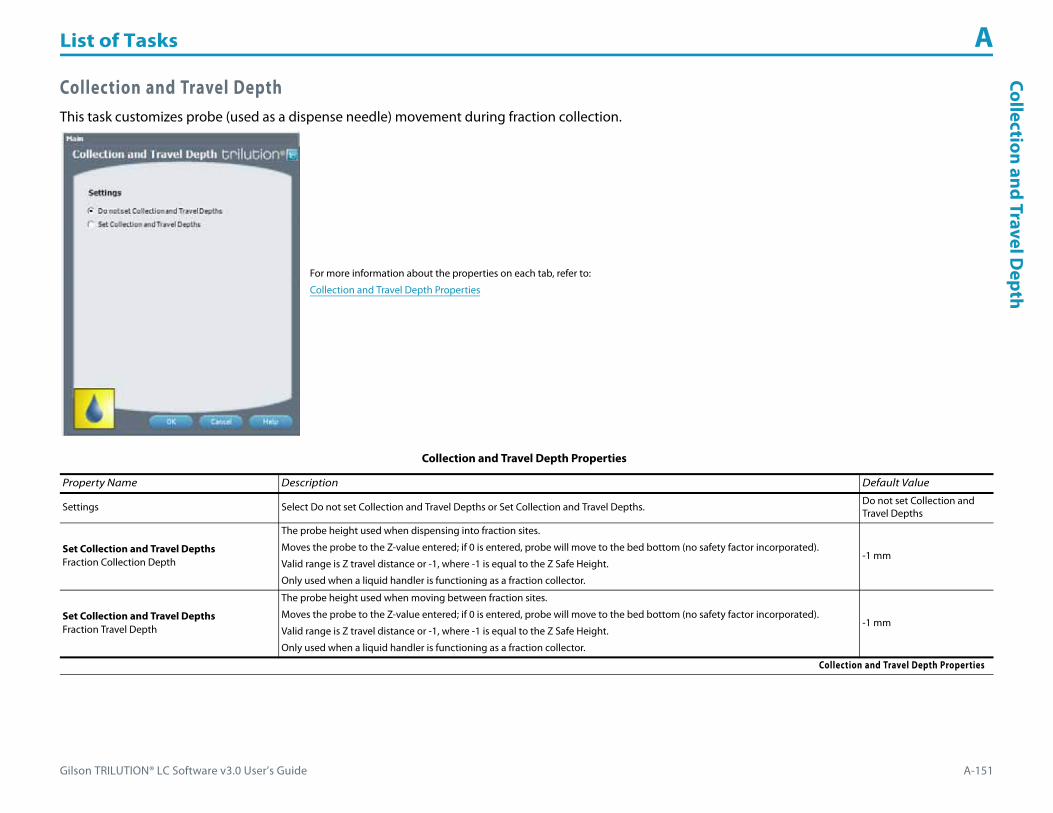
Gilson TRILUTION® LC Software v3.0 User’s Guide A-151
List of Tasks ACollection and Travel D
epth
Collection and Travel DepthThis task customizes probe (used as a dispense needle) movement during fraction collection.
For more information about the properties on each tab, refer to:
Collection and Travel Depth Properties
Collection and Travel Depth Properties
Property Name Description Default Value
Settings Select Do not set Collection and Travel Depths or Set Collection and Travel Depths. Do not set Collection and Travel Depths
Set Collection and Travel DepthsFraction Collection Depth
The probe height used when dispensing into fraction sites.
Moves the probe to the Z-value entered; if 0 is entered, probe will move to the bed bottom (no safety factor incorporated).
Valid range is Z travel distance or -1, where -1 is equal to the Z Safe Height.
Only used when a liquid handler is functioning as a fraction collector.
-1 mm
Set Collection and Travel DepthsFraction Travel Depth
The probe height used when moving between fraction sites.
Moves the probe to the Z-value entered; if 0 is entered, probe will move to the bed bottom (no safety factor incorporated).
Valid range is Z travel distance or -1, where -1 is equal to the Z Safe Height.
Only used when a liquid handler is functioning as a fraction collector.
-1 mm
Collection and Travel Depth Properties

List of Tasks A
A-152 Gilson TRILUTION® LC Software v3.0 User’s Guide
Cond
itio
nal F
ract
ion
Colle
ctio
n Conditional Fraction CollectionThe Conditional Fraction Collection task enables setting up conditional logic fraction collection using data on up to eight channels. This is ideal in a Gilson LC/MS Purification System for using both UV and MS detection to trigger collection. This task can be used in place of the Fraction Collection Settings task.
How to Set Up Conditional Fraction Collection1 Ensure that there are data channels in the configuration that are set for use and that the method contains the
Start Data Collection and Stop Data Collection tasks.2 Drag the Conditional Fraction Collection Task (which is listed under Auxiliary tasks) and drop it in the workspace.3 Select the primary condition (either slope or level) on the primary channel. Use of a UV channel as the primary
channel is recommended. 4 Select the AND option button to indicate that fraction collection will occur when the condition on the primary
channel is met AND the condition on all secondary conditions are met.Alternatively, select the OR option button to indicate that fraction collection will occur when the condition on the primary channel is met OR any secondary condition is met.Alternatively, select the AND/OR option button to indicate that fraction collection will occur when the condition on the primary channel is met AND any secondary condition is met.
5 Set conditions on up to seven additional channels using the tabs. The text color of the tab number changes from red to green when a channel has been selected and conditions have been set. Each condition could use a different channel or multiple conditions could be set up on the same secondary channel.
6 Optionally, select the Co-eluted Peaks check box to collect co-eluted peaks.7 Optionally, select the Collect Non Peaks check box to collect non peaks.8 Select the Fraction Sites tab.
a) If using a liquid handler as a fraction collector, optionally set the collection and travel depths. The fraction collection depth is the probe height used when dispensing into fraction sites. The fraction travel depth is the probe height used when moving between fraction sites. The probe will move to the Z-value entered; if 0 is entered, the probe will move to the bed bottom (no safety factor incorporated). The valid range is the Z travel distance or -1, where -1 is equal to the Z Safe Height.
b) Select a fraction collector and zone where fraction collection will begin for an injected sample (Fraction Site 1). The default fraction well is 0, the indication for continuous collection where fractions are always collected in the next available tube.
c) Select up to three additional fraction collectors and/or zones (Fraction Site 2, Fraction Site 3, and Fraction Site 4).9 If subdividing, drag the Set Peak Per Tube or Set Non Peak Per Tube task and then drop it in the workspace after the Conditional Fraction Collection task. For
non peak collection, select the Collect Non Peak check box. Subdivision can be by time or volume.10 Add the Start Fraction Collection (after the Set Peak Per Tube or Set Non Peak Per Tube task) and the Stop Fraction Collection tasks to the method.
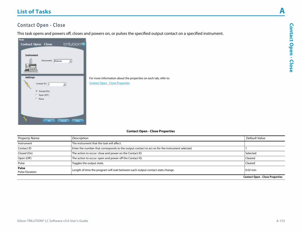
Gilson TRILUTION® LC Software v3.0 User’s Guide A-153
List of Tasks AContact O
pen - Close
Contact Open - CloseThis task opens and powers off, closes and powers on, or pulses the specified output contact on a specified instrument.
For more information about the properties on each tab, refer to:
Contact Open - Close Properties
Contact Open - Close Properties
Property Name Description Default Value
Instrument The instrument that the task will affect.
Contact ID Enter the number that corresponds to the output contact to act on for the instrument selected. 1
Closed (On) The action to occur: close and power on the Contact ID. Selected
Open (Off ) The action to occur: open and power off the Contact ID. Cleared
Pulse Toggles the output state. Cleared
PulsePulse Duration
Length of time the program will wait between each output contact state change. 0.02 min
Contact Open - Close Properties

List of Tasks A
A-154 Gilson TRILUTION® LC Software v3.0 User’s Guide
Det
ecto
r Aut
ozer
o Ch
anne
l Detector Autozero ChannelThis task sets the signal of each channel on the selected Detector to zero.
For more information about the properties on each tab, refer to:
Detector Autozero Channel Properties
Detector Autozero Channel Properties
Property Name Description Default Value
Detector The detector that the task will affect. Detector
Detector Autozero Channel Properties
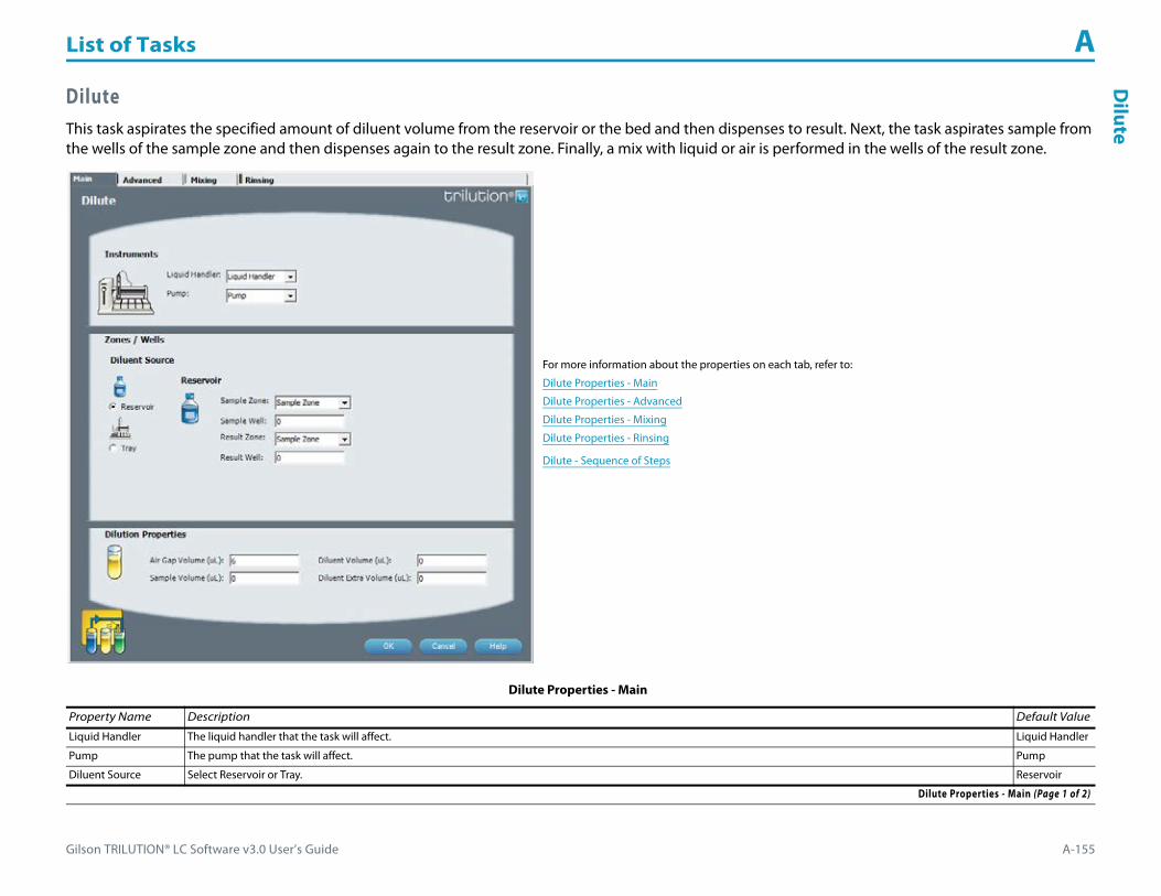
Gilson TRILUTION® LC Software v3.0 User’s Guide A-155
List of Tasks AD
ilute
DiluteThis task aspirates the specified amount of diluent volume from the reservoir or the bed and then dispenses to result. Next, the task aspirates sample from the wells of the sample zone and then dispenses again to the result zone. Finally, a mix with liquid or air is performed in the wells of the result zone.
For more information about the properties on each tab, refer to:
Dilute Properties - Main
Dilute Properties - Advanced
Dilute Properties - Mixing
Dilute Properties - Rinsing
Dilute - Sequence of Steps
Dilute Properties - Main
Property Name Description Default Value
Liquid Handler The liquid handler that the task will affect. Liquid Handler
Pump The pump that the task will affect. Pump
Diluent Source Select Reservoir or Tray. Reservoir
Dilute Properties - Main (Page 1 of 2)

List of Tasks A
A-156 Gilson TRILUTION® LC Software v3.0 User’s Guide
Dilu
te
ReservoirSample Zone
The zone from which the Sample Volume is aspirated. Sample Zone
ReservoirSample Well
Enter the well number in the Sample Zone. 0
ReservoirResult Zone
The zone to which the Sample Volume and Diluent Volume are delivered. Sample Zone
ReservoirResult Well
Enter the well number in the Result Zone. 0
TraySample Zone
The zone from which the Sample Volume is aspirated. Sample Zone
TraySample Well
Enter the well number in the Sample Zone. 0
TrayDiluent Zone
The zone from which the Diluent Volume is aspirated. Sample Zone
TrayDiluent Well
Enter the well number in the Diluent Zone. 0
TrayResult Zone
The zone to which the Sample Volume and Diluent Volume are delivered. Sample Zone
TrayResult Well
Enter the well number in the Result Zone. 0
Air Gap Volume The quantity of an air gap. 6 μL
Sample Volume The quantity of sample. 0 μL
Diluent Volume The quantity of liquid used to dilute the sample volume in the Sample Well in the Sample Zone. 0 μL
Diluent Extra Volume When Tray is selected; an additional volume to the first volume aspirated. It ensures that the actual volume of liquid to be transferred is not contaminated and acts as an extra buffer between the air gap/reservoir solvent and the Diluent Volume. 0 μL
Dilute Properties - Advanced
Property Name Description Default Value
Sample Flow Rate The speed at which the Sample Volume moves into the probe. 1.5 mL/min
Diluent Flow Rate The speed at which the Diluent Volume moves into the probe. 1.5 mL/min
Dispense Flow Rate The speed at which the volume moves out of the probe. 3 mL/min
Air Gap Flow Rate The speed at which the Air Gap Volume moves into the probe. 0.3 mL/min
Dilute Properties - Advanced (Page 1 of 2)
Dilute Properties - Main (Continued)
Property Name Description Default Value
Dilute Properties - Main (Page 2 of 2)

Gilson TRILUTION® LC Software v3.0 User’s Guide A-157
List of Tasks AD
ilute
Sample Z Option
One of six defined reference points used when aspirating the Sample Volume from the bed:Auto Calculate: Places probe into well and at the liquid level using initial volume from the sample list and well dimensions from the bed layout; accepts a positive (+) or negative (-) value for the Sample Z Offset.Absolute Value: Moves the probe to the Z-value entered; if 0 is entered, probe will move to the bed bottom (no safety factor incorporated).Tube Bottom: Moves the probe to the well bottom as defined by the bed layout; accepts only positive Sample Z Offset value to move up from the bottom.Top: Moves probe to the top of their Z-travel range; accepts only a negative (-) value for the Sample Z Offset.Tube Top: Moves the probe to the top of the well as defined by the bed layout; accepts a positive (+) or negative (-) value for the Sample Z Offset.Z Adjust: Moves the probe from the current position up (positive value) or down (negative value).
Tube Bottom
Sample Z Offset The distance up (when a positive number is entered) or down (when a negative number is entered) from a reference point defined by the Sample Z Option used when aspirating the Sample Volume from the bed.
2 mm
Aspirate Sample LLFWhen selected, the probe will follow the liquid down as it is aspirated from the Sample Zone. The Sample Z Option must be set to AUTO CALCULATE and initial volumes must be set in the sample list to use this option.
When cleared, the probe will not follow the liquid down as it is aspirated from the Sample Zone.Cleared
Diluent Z Option
One of six defined reference points used when aspirating the Diluent Volume from the bed:Auto Calculate: Places probe into well and at the liquid level using initial volume from the sample list and well dimensions from the bed layout; accepts a positive (+) or negative (-) value for the Diluent Z Offset.Absolute Value: Moves the probe to the Z-value entered; if 0 is entered, probe will move to the bed bottom (no safety factor incorporated).Tube Bottom: Moves the probe to the well bottom as defined by the bed layout; accepts only positive Diluent Z Offset value to move up from the bottom.Top: Moves probe to the top of their Z-travel range; accepts only a negative (-) value for the Diluent Z Offset.Tube Top: Moves the probe to the top of the well as defined by the bed layout; accepts a positive (+) or negative (-) value for the Diluent Z Offset.Z Adjust: Moves the probe from the current position up (positive value) or down (negative value).
Tube Bottom
Diluent Z Offset When selected, the distance up (when a positive number is entered) or down (when a negative number is entered) from a reference point defined by the Diluent Z Option used when aspirating the Diluent Volume from the bed. 2 mm
Aspirate Diluent LLFWhen selected, the probe will follow the liquid down as it is aspirated from the Diluent Zone. The Aspirate Z Option must be set to AUTO CALCULATE and initial volumes must be set in the sample list to use this option.
When cleared, the probe will not follow the liquid down as it is aspirated from the Diluent Zone.Cleared
Result Z Option
One of six defined reference points used when delivering the Diluent Volume, Sample Volume, and Air Gap Volume to the bed:Auto Calculate: Places probe into well and at the liquid level using initial volume from the sample list and well dimensions from the bed layout; accepts a positive (+) or negative (-) value for the Result Z Offset.Absolute Value: Moves the probe to the Z-value entered; if 0 is entered, probe will move to the bed bottom (no safety factor incorporated).Tube Bottom: Moves the probe to the well bottom as defined by the bed layout; accepts only positive Result Z Offset value to move up from the bottom.Top: Moves probe to the top of their Z-travel range; accepts only a negative (-) value for the Result Z Offset.Tube Top: Moves the probe to the top of the well as defined by the bed layout; accepts a positive (+) or negative (-) value for the Result Z Offset.Z Adjust: Moves the probe from the current position up (positive value) or down (negative value).
Tube Bottom
Result Z Offset The distance up (when a positive number is entered) or down (when a negative number is entered) from a reference point defined by the Result Z Option used when delivering the Diluent Volume, Sample Volume, and Air Gap Volume to the bed. 2 mm
Dispense LLFWhen selected, the probe will follow the liquid up as it is delivered to the Result Zone. The Result Z Option must be set to AUTO CALCULATE and initial volumes must be set in the sample list to use this option.
When cleared, the probe will not follow the liquid up as it is delivered to the Result Zone.Cleared
Dilute Properties - Advanced (Continued)
Property Name Description Default Value
Dilute Properties - Advanced (Page 2 of 2)

List of Tasks A
A-158 Gilson TRILUTION® LC Software v3.0 User’s Guide
Dilu
te Dilute Properties - Mixing
Property Name Description Default Value
Mixing Properties Select Mix with Liquid or Mix with Air to perform a mix of the Diluent Volume with the Sample Volume. Select No Mix for no mixing. No Mix
Mix with LiquidNumber of Cycles
The number of times the task should repeat the commands related to mixing. 2
Mix with LiquidMixing Volume
The quantity of liquid used as part of a mixing process. 0 μL
Mix with LiquidMix Aspirate Flow Rate
The speed at which volumes move into the probe during the mixing process. 1 mL/min
Mix with LiquidMix Dispense Flow Rate
The speed at which volumes move out of the probe during the mixing process. 10 mL/min
Mix with LiquidMix Aspirate Z Option
One of six defined reference points used when aspirating the Mixing Volume from the bed:Auto Calculate: Places probe into well and at the liquid level using initial volume from the sample list and well dimensions from the bed layout; accepts a positive (+) or negative (-) value for the Mix Aspirate Z Offset.Absolute Value: Moves the probe to the Z-value entered; if 0 is entered for the Mix Aspirate Z Offset, the probe will move to the bed bottom (no safety factor incorporated).Tube Bottom: Moves the probe to the well bottom as defined by the bed layout; accepts only positive Mix Aspirate Z Offset value to move up from the bottom.Top: Moves probe to the top of their Z-travel range; accepts only a negative (-) value for the Mix Aspirate Z Offset.Tube Top: Moves the probe to the top of the well as defined by the bed layout; accepts a positive (+) or negative (-) value for the Mix Aspirate Z Offset.Z Adjust: Moves the probe from the current position up (positive value) or down (negative value).
Tube Bottom
Mix with LiquidMix Aspirate Z Offset
The distance up (when a positive number is entered) or down (when a negative number is entered) from a reference point defined by the Mix Aspirate Z Option used when aspirating the Mixing Volume from the bed. 2 mm
Mix with LiquidAspirate LLF
When selected, the probe will follow the liquid down as it is aspirated from the Diluent Zone. The Aspirate Z Option must be set to AUTO CALCULATE and initial volumes must be set in the sample list to use this option.
When cleared, the probe will not follow the liquid down as it is aspirated from the Diluent Zone.Cleared
Mix with LiquidMix Dispense Z Option
One of six defined reference points used when delivering the Mixing Volume to the bed:Auto Calculate: Places probe into well and at the liquid level using initial volume from the sample list and well dimensions from the bed layout; accepts a positive (+) or negative (-) value for the Mix Dispense Z Offset.Absolute Value: Moves the probe to the Z-value entered; if 0 is entered for the Mix Dispense Z Offset, the probe will move to the bed bottom (no safety factor incorporated).Tube Bottom: Moves the probe to the well bottom as defined by the bed layout; accepts only positive Mix Dispense Z Offset value to move up from the bottom.Top: Moves probe to the top of their Z-travel range; accepts only a negative (-) value for the Mix Dispense Z Offset.Tube Top: Moves the probe to the top of the well as defined by the bed layout; accepts a positive (+) or negative (-) value for the Mix Dispense Z Offset.Z Adjust: Moves the probe from the current position up (positive value) or down (negative value).
Tube Bottom
Mix with LiquidMix Dispense Z Offset
The distance up (when a positive number is entered) or down (when a negative number is entered) from a reference point defined by the Mix Dispense Z Option used when delivering the Mixing Volume to the bed. 2 mm
Mix with LiquidMix Dispense LLF
When selected, the probe will follow the liquid up as it is delivered to the Sample Zone as part of the mixing process. The Mix Dispense Z Option must be set to AUTO CALCULATE and initial volumes must be set in the sample list to use this option.
When cleared, the probe will not follow the liquid up as it is delivered to the Sample Zone as part of the mixing process.Cleared
Mix with AirNumber of Cycles
Type the number of times the task should repeat the commands related to mixing. 2
Mix with AirMixing Volume
The quantity of air used as part of a mixing process. 0 μL
Dilute Properties - Mixing (Page 1 of 2)

Gilson TRILUTION® LC Software v3.0 User’s Guide A-159
List of Tasks AD
ilute
Mix with AirMix Aspirate Flow Rate
The speed at which volumes move into the probe during the mixing process. 1 mL/min
Mix with AirMix Dispense Flow Rate
The speed at which volumes move out of the probe during the mixing process. 10 mL/min
Mix with AirMix Dispense Z Option
One of six defined reference points used when delivering the Mixing Volume to the bed:Auto Calculate: Places probe into well and at the liquid level using initial volume from the sample list and well dimensions from the bed layout; accepts a positive (+) or negative (-) value for the Mix Dispense Z Offset.Absolute Value: Moves the probe to the Z-value entered; if 0 is entered for the Mix Dispense Z Offset, the probe will move to the bed bottom (no safety factor incorporated).Tube Bottom: Moves the probe to the well bottom as defined by the bed layout; accepts only positive Mix Dispense Z Offset value to move up from the bottom.Top: Moves probe to the top of their Z-travel range; accepts only a negative (-) value for the Mix Dispense Z Offset.Tube Top: Moves the probe to the top of the well as defined by the bed layout; accepts a positive (+) or negative (-) value for the Mix Dispense Z Offset.Z Adjust: Moves the probe from the current position up (positive value) or down (negative value).
Tube Bottom
Mix with AirMix Dispense Z Offset
The distance up (when a positive number is entered) or down (when a negative number is entered) from a reference point defined by the Mix Dispense Z Option used when delivering the Mixing Volume to the bed. 2 mm
Mix with AirMix Dispense LLF
When selected, the probe will follow the liquid up as it is delivered to the Sample Zone as part of the mixing process. The Mix Dispense Z Option must be set to AUTO CALCULATE and initial volumes must be set in the sample list to use this option.
When cleared, the probe will not follow the liquid up as it is delivered to the Sample Zone as part of the mixing process.Cleared
Dilute Properties - Rinsing For information about rinse positions, refer to Appendix B, Rinse Locations.
Property Name Description Default Value
Inside Rinse Zone The zone to which the Inside Rinse Volume is delivered. Inside Rinse
Inside Rinse Well Enter the well number in the Inside Rinse Zone. 1
Inside Rinse Volume The quantity of liquid used to rinse the inside of the probe. 250 μL
Inside Rinse Flow Rate The speed at which the Inside Rinse Volume moves out of the probe and into the inside rinse position in the rinse station. 10 mL/min
Inside Rinse Z Option
One of six defined reference points used when performing the inside rinse:Auto Calculate: Places probe into well and at the liquid level using initial volume from the sample list and well dimensions from the bed layout; accepts a positive (+) or negative (-) value for the Inside Rinse Z Offset.Absolute Value: Moves the probe to the Z-value entered; if 0 is entered, probe will move to the bed bottom (no safety factor incorporated).Tube Bottom: Moves the probe to the well bottom as defined by the bed layout; accepts only positive Inside Rinse Z Offset values to move up from the bottom.Top: Moves probe to the top of their Z-travel range; accepts only a negative (-) value for the Inside Rinse Z Offset.Tube Top: Moves the probe to the top of the well as defined by the bed layout; accepts a positive (+) or negative (-) value for the Inside Rinse Z Offset.Z Adjust: Moves the probe from the current position up (positive value) or down (negative value).
Tube Bottom
Inside Rinse Z Offset The distance up (when a positive number is entered) or down (when a negative number is entered) from a reference point defined by the Inside Rinse Z Option for rinsing the probe at the inside rinse position in the rinse station. 2 mm
Outside Rinse Zone The zone to which the Outside Rinse Volume is delivered. Outside Rinse
Outside Rinse Well Enter the well number in the Outside Rinse Zone. 1
Dilute Properties - Rinsing (Page 1 of 2)
Dilute Properties - Mixing (Continued)
Property Name Description Default Value
Dilute Properties - Mixing (Page 2 of 2)
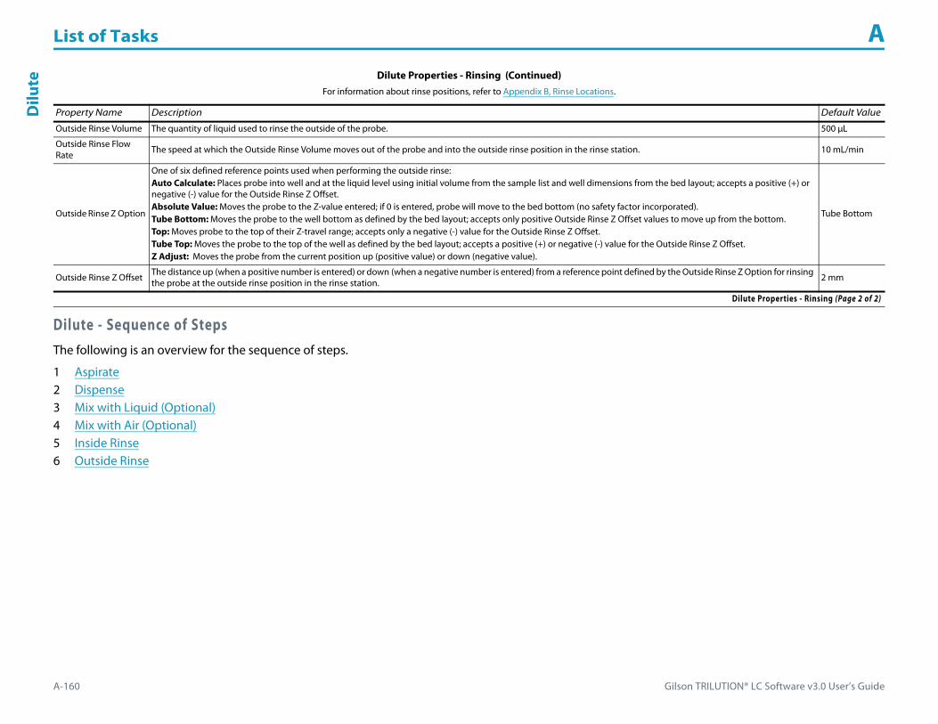
List of Tasks A
A-160 Gilson TRILUTION® LC Software v3.0 User’s Guide
Dilu
te
Dilute - Sequence of StepsThe following is an overview for the sequence of steps.
1 Aspirate2 Dispense3 Mix with Liquid (Optional)4 Mix with Air (Optional)5 Inside Rinse6 Outside Rinse
Outside Rinse Volume The quantity of liquid used to rinse the outside of the probe. 500 μL
Outside Rinse Flow Rate The speed at which the Outside Rinse Volume moves out of the probe and into the outside rinse position in the rinse station. 10 mL/min
Outside Rinse Z Option
One of six defined reference points used when performing the outside rinse:Auto Calculate: Places probe into well and at the liquid level using initial volume from the sample list and well dimensions from the bed layout; accepts a positive (+) or negative (-) value for the Outside Rinse Z Offset.Absolute Value: Moves the probe to the Z-value entered; if 0 is entered, probe will move to the bed bottom (no safety factor incorporated).Tube Bottom: Moves the probe to the well bottom as defined by the bed layout; accepts only positive Outside Rinse Z Offset values to move up from the bottom.Top: Moves probe to the top of their Z-travel range; accepts only a negative (-) value for the Outside Rinse Z Offset.Tube Top: Moves the probe to the top of the well as defined by the bed layout; accepts a positive (+) or negative (-) value for the Outside Rinse Z Offset.Z Adjust: Moves the probe from the current position up (positive value) or down (negative value).
Tube Bottom
Outside Rinse Z Offset The distance up (when a positive number is entered) or down (when a negative number is entered) from a reference point defined by the Outside Rinse Z Option for rinsing the probe at the outside rinse position in the rinse station. 2 mm
Dilute Properties - Rinsing (Continued)For information about rinse positions, refer to Appendix B, Rinse Locations.
Property Name Description Default Value
Dilute Properties - Rinsing (Page 2 of 2)
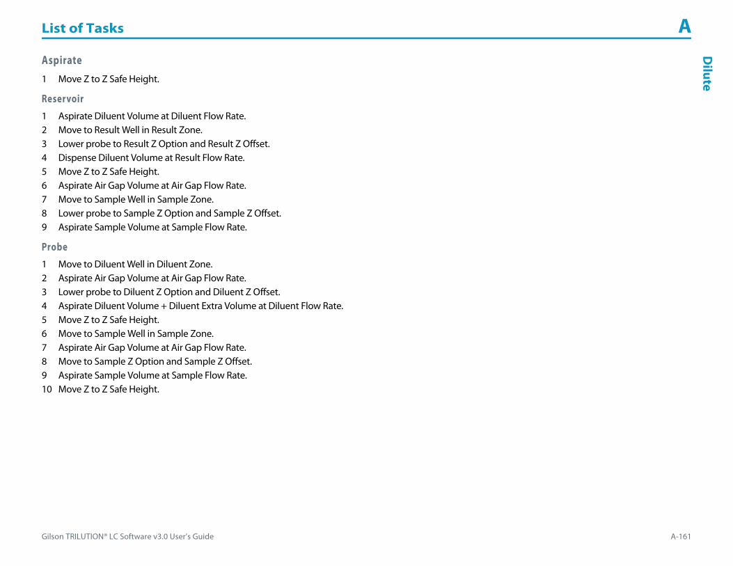
Gilson TRILUTION® LC Software v3.0 User’s Guide A-161
List of Tasks AD
ilute
Aspirate1 Move Z to Z Safe Height.
Reservoir1 Aspirate Diluent Volume at Diluent Flow Rate.2 Move to Result Well in Result Zone.3 Lower probe to Result Z Option and Result Z Offset.4 Dispense Diluent Volume at Result Flow Rate.5 Move Z to Z Safe Height.6 Aspirate Air Gap Volume at Air Gap Flow Rate.7 Move to Sample Well in Sample Zone.8 Lower probe to Sample Z Option and Sample Z Offset.9 Aspirate Sample Volume at Sample Flow Rate.
Probe1 Move to Diluent Well in Diluent Zone.2 Aspirate Air Gap Volume at Air Gap Flow Rate.3 Lower probe to Diluent Z Option and Diluent Z Offset.4 Aspirate Diluent Volume + Diluent Extra Volume at Diluent Flow Rate.5 Move Z to Z Safe Height.6 Move to Sample Well in Sample Zone.7 Aspirate Air Gap Volume at Air Gap Flow Rate.8 Move to Sample Z Option and Sample Z Offset.9 Aspirate Sample Volume at Sample Flow Rate.10 Move Z to Z Safe Height.
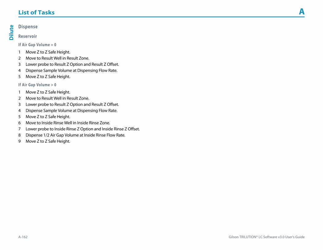
List of Tasks A
A-162 Gilson TRILUTION® LC Software v3.0 User’s Guide
Dilu
te Dispense
Reservoir
If Air Gap Volume = 0
1 Move Z to Z Safe Height.2 Move to Result Well in Result Zone.3 Lower probe to Result Z Option and Result Z Offset.4 Dispense Sample Volume at Dispensing Flow Rate.5 Move Z to Z Safe Height.
If Air Gap Volume > 0
1 Move Z to Z Safe Height.2 Move to Result Well in Result Zone.3 Lower probe to Result Z Option and Result Z Offset.4 Dispense Sample Volume at Dispensing Flow Rate.5 Move Z to Z Safe Height.6 Move to Inside Rinse Well in Inside Rinse Zone.7 Lower probe to Inside Rinse Z Option and Inside Rinse Z Offset.8 Dispense 1/2 Air Gap Volume at Inside Rinse Flow Rate.9 Move Z to Z Safe Height.

Gilson TRILUTION® LC Software v3.0 User’s Guide A-163
List of Tasks AD
ilute
Probe
If Diluent Extra Volume = 0
1 Move Z to Z Safe Height.2 Move to Result Well in Result Zone.3 Lower probe to Result Z Option and Result Z Offset.4 Dispense Sample Volume + Air Gap Volume + Diluent Volume +1/2 Air Gap Volume at Dispense Flow Rate.5 Move Z to Z Safe Height.
If Diluent Extra Volume > 0
1 Move Z to Z Safe Height.2 Move to Result Well in Result Zone.3 Lower probe to Result Z Option and Result Z Offset.4 Dispense Sample Volume + Air Gap Volume + Diluent Volume at Result Flow Rate.5 Move Z to Z Safe Height.6 Move to Inside Rinse Well in Inside Rinse Zone.7 Lower probe to Inside Rinse Z Option and Inside Rinse Z Offset.8 Dispense Diluent Extra Volume + Air Gap Volume at Inside Rinse Flow Rate.9 Move Z to Z Safe Height.
Mix with Liquid (Optional)1 Move Z to Z Safe Height.2 Aspirate Air Gap Volume at Air Gap Flow Rate.3 Move to Sample Well in Sample Zone.4 Lower probe to Mix Aspirate Z Option and Mix Aspirate Z Offset.5 Aspirate Mixing Volume at Mix Aspirate Flow Rate.6 Lower probe to Mix Dispense Z Option and Mix Dispense Z Offset.7 Dispense Mixing Volume at Mix Dispense Flow Rate.8 Repeat steps 4–7 for Number of Cycles.9 Move Z to Z Safe Height.

List of Tasks A
A-164 Gilson TRILUTION® LC Software v3.0 User’s Guide
Dilu
te Mix with Air (Optional)1 Move Z to Z Safe Height.2 Move to Sample Well in Sample Zone.3 Move Z to Z Safe Height.4 Aspirate Air Gap Volume at Air Gap Flow Rate (first cycle only).5 Aspirate Mixing Volume at Mix Aspirate Flow Rate.6 Lower probe to Mix Dispense Z Option and Mix Dispense Z Offset.7 Dispense Mixing Volume at Mix Dispense Flow Rate.8 Repeat steps 3–7 for Number of Cycles.9 Move Z to Z Safe Height.
Inside Rinse1 Move to Inside Rinse Well in Inside Rinse Zone.2 Lower probe into well to Inside Rinse Z Option and Inside Rinse Z Offset.3 Home dilutor.4 Aspirate Inside Rinse Volume or syringe capacity (from Reservoir) at Inside Rinse Flow Rate.5 Dispense Inside Rinse Volume or syringe capacity at Inside Rinse Flow Rate.6 Repeat steps 4–5 until requested rinse volume is aspirated and dispensed.7 Move Z to Z Safe Height.
Outside Rinse1 Move to Outside Rinse Well in Outside Rinse Zone.2 Lower probe into well to Outside Rinse Z Option and Outside Rinse Z Offset.3 Home dilutor.4 Aspirate Outside Rinse Volume or syringe capacity (from Reservoir) at Outside Rinse Flow Rate.5 Dispense Outside Rinse Volume or syringe capacity at Outside Rinse Flow Rate.6 Repeat steps 4–5 until requested rinse volume is aspirated and dispensed.

Gilson TRILUTION® LC Software v3.0 User’s Guide A-165
List of Tasks AD
ispense
DispenseThis task delivers liquid or air and must be synchronized with a Move to Sample Location task to move the probe to the well before dispensing.
For more information about the properties on each tab, refer to:
Dispense Properties
Dispense Properties
Property Name Description Default Value
Instrument The liquid handler that the task will affect. Liquid Handler
Pump The pump that the task will affect. Pump
Liquid Level FollowingWhen selected, the probe will follow the liquid up as it is dispensed. The Z Option for the Move to Sample Location task must be set to AUTO CALCULATE and initial volumes must be set in the sample list to use this option.
When cleared, the probe will not follow the liquid up as it is dispensed to the Sample Zone in the Move to Sample Location task.Cleared
Solvent Valve PositionThe desired position of the solvent selection valve on the GX Solvent System. Valid range is 1–6.
The position designated for waste cannot be used for a solvent.2
Dispense Volume The quantity of liquid or air to be dispensed. 0 μL
Dispense Flow Rate The speed at which the volume moves out of the probe. 0 mL/min
Dispense Properties

List of Tasks A
A-166 Gilson TRILUTION® LC Software v3.0 User’s Guide
Exec
ute Execute
This task invokes an external application.
For more information about the properties on each tab, refer to:
Execute Properties
Execute Properties
Property Name Description Default Value
Path and Name File path to which the Command Line Parameters are sent. Click to browse for the executable program.
Command Line Parameters The information sent to the program located at the Path and Name.
Synchronize Synchronize selected waits for the external program to close before continuing task execution. Synchronize cleared launches the external program and then immediately resumes task execution. Cleared
Execute Properties

Gilson TRILUTION® LC Software v3.0 User’s Guide A-167
List of Tasks AFraction
Collection Settings
Fraction Collection SettingsThis task sets all parameters for fraction collection. For more information about fraction collection, refer to Appendix D, Fraction Collection Techniques.
For more information about the properties on each tab, refer to:
Fraction Collection Settings Properties - Main
Fraction Collection Settings Properties - Fraction Sites
Fraction Collection Settings Properties - Main
Property Name Description Default Value
Fraction Collection Mode Slope, Level, Time, or Volume Slope
SlopePeak Front Slope
Consider the angle of the peak’s ascending edge when setting the value for Peak Front Slope.
A smaller Peak Front Slope value will collect smaller, sharper peaks. To reduce the number of small peaks collected, increase the Peak Front Slope value.
25
SlopePeak Back Slope
Consider the angle of the peak’s descending edge when setting the value for Peak Back Slope.
If the peak has significant tailing, the Peak Back Slope value should be increased to reduce the amount of the tail that is collected or decreased to increase the amount of the tail that is collected.
25
SlopePeak Width
The size of the data window that is used to calculate whether the slope condition has been met. If the trace has a lot of noise, set a higher value to reduce the number of smaller peaks that are collected or set a lower value to increase the number of smaller peaks that are collected.
0.2 min
Fraction Collection Settings Properties - Main (Page 1 of 2)

List of Tasks A
A-168 Gilson TRILUTION® LC Software v3.0 User’s Guide
Frac
tion
Colle
ctio
n Se
ttin
gs
SlopeSubdivided Peaks
Select from None, Time, or Volume
If collecting primarily by Slope or Level, this option allows you to subdivide the peak collection by Time or Volume.None
Slope - Subdivide PeaksTime Per Tube
Enter the time to dispense at each tube. 0 min
Slope -Subdivide PeaksVolume Per Tube
Enter the maximum volume to be collected into each tube. 0 μL
SlopeNon Peaks
Indicates if all non peaks should be collected into tubes (TRUE) or not (FALSE). When TRUE, select from None, Time, or Volume. FALSE
Slope - Non PeaksTime Per Tube
Enter the time to dispense at each tube when collecting non peaks. 0 min
Slope - Non PeaksVolume Per Tube
Enter the maximum volume of non peak effluent to be collected into each tube. 0 μL
SlopeCollection Region
Indicate whether the front of the slope to the apex (Front APEX), the apex to the tail (APEX Tail) or the entire peak (ALL) should be collected. To collect the entire peak, but advance to the next well at the apex, select APEX.
Refer to Appendix D, Fraction Collection Techniques for examples of how the Collection Region option is used.ALL
SlopeCollect Negative Peaks
Select to turn on or clear to turn off the collection of negative and positive peaks Cleared
SlopeCo-eluted Peaks
Select to turn on or clear to turn off the collection of co-eluted peaks. Cleared
LevelPeak Level
When the Fraction Collection Mode selected is Level; the level above which all peaks are collected. This value is especially useful if the detector signal should go off-scale during collection. 0
LevelCollect Negative Peak
Select to turn on or clear to turn off the collection of negative peaks Cleared
LevelSubdivided Peaks
Select from None, Time, or Volume.
If collecting primarily by Slope or Level, this option allows you to subdivide the peak collection by Time or Volume.None
Level - Subdivide PeaksTime Per Tube
Enter the time to dispense at each tube. 0 min
Level -Subdivide PeaksVolume Per Tube
Enter the maximum volume to be collected into each tube. 0 μL
LevelCollect Non Peak
Indicates if all non peaks should be collected into tubes (TRUE) or not (FALSE). FALSE
Level - Non PeaksTime Per Tube
Enter the time to dispense at each tube when collecting non peaks. 0 min
Level - Non PeaksVolume Per Tube
Enter the maximum volume of non peak effluent to be collected into each tube. 0 μL
TimeTime per Tube
Enter the time to dispense at each tube. 0 min
VolumeVolume per Tube
Enter the maximum volume to be collected into each tube. 0 μL
Fraction Collection Settings Properties - Main (Continued)
Property Name Description Default Value
Fraction Collection Settings Properties - Main (Page 2 of 2)
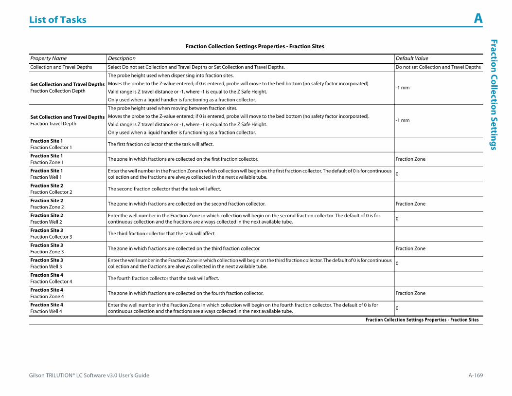
Gilson TRILUTION® LC Software v3.0 User’s Guide A-169
List of Tasks AFraction
Collection Settings
Fraction Collection Settings Properties - Fraction Sites
Property Name Description Default Value
Collection and Travel Depths Select Do not set Collection and Travel Depths or Set Collection and Travel Depths. Do not set Collection and Travel Depths
Set Collection and Travel DepthsFraction Collection Depth
The probe height used when dispensing into fraction sites.
Moves the probe to the Z-value entered; if 0 is entered, probe will move to the bed bottom (no safety factor incorporated).
Valid range is Z travel distance or -1, where -1 is equal to the Z Safe Height.
Only used when a liquid handler is functioning as a fraction collector.
-1 mm
Set Collection and Travel DepthsFraction Travel Depth
The probe height used when moving between fraction sites.
Moves the probe to the Z-value entered; if 0 is entered, probe will move to the bed bottom (no safety factor incorporated).
Valid range is Z travel distance or -1, where -1 is equal to the Z Safe Height.
Only used when a liquid handler is functioning as a fraction collector.
-1 mm
Fraction Site 1Fraction Collector 1
The first fraction collector that the task will affect.
Fraction Site 1Fraction Zone 1
The zone in which fractions are collected on the first fraction collector. Fraction Zone
Fraction Site 1Fraction Well 1
Enter the well number in the Fraction Zone in which collection will begin on the first fraction collector. The default of 0 is for continuous collection and the fractions are always collected in the next available tube. 0
Fraction Site 2Fraction Collector 2
The second fraction collector that the task will affect.
Fraction Site 2Fraction Zone 2
The zone in which fractions are collected on the second fraction collector. Fraction Zone
Fraction Site 2Fraction Well 2
Enter the well number in the Fraction Zone in which collection will begin on the second fraction collector. The default of 0 is for continuous collection and the fractions are always collected in the next available tube. 0
Fraction Site 3Fraction Collector 3
The third fraction collector that the task will affect.
Fraction Site 3Fraction Zone 3
The zone in which fractions are collected on the third fraction collector. Fraction Zone
Fraction Site 3Fraction Well 3
Enter the well number in the Fraction Zone in which collection will begin on the third fraction collector. The default of 0 is for continuous collection and the fractions are always collected in the next available tube. 0
Fraction Site 4Fraction Collector 4
The fourth fraction collector that the task will affect.
Fraction Site 4Fraction Zone 4
The zone in which fractions are collected on the fourth fraction collector. Fraction Zone
Fraction Site 4Fraction Well 4
Enter the well number in the Fraction Zone in which collection will begin on the fourth fraction collector. The default of 0 is for continuous collection and the fractions are always collected in the next available tube. 0
Fraction Collection Settings Properties - Fraction Sites

List of Tasks A
A-170 Gilson TRILUTION® LC Software v3.0 User’s Guide
Frac
tion
Col
lect
ion
Valv
e Ri
nse Fraction Collection Valve Rinse
This task rinses the fraction collection valve for a user-specified duration.
For more information about the properties on each tab, refer to:
Fraction Collection Valve Rinse Properties - Main
Fraction Collection Valve Rinse - Sequence of Steps
Fraction Collection Valve Rinse Properties - Main
Property Name Description Default Value
Fraction Collector The fraction collector that the task will affect. Fraction Collector
Drain Zone The zone in which the fraction collection valve is rinsed. Inside Rinse
Drain Well Enter the well number in the Drain Zone. 1
Fraction Collection Valve Rinse Time After the valve switches to COLLECT, the length of time the valve is rinsed before switching the valve back to DIVERT. 0.05 min
Do not set Fraction Site Select this option to set the Fraction Site with a separate task prior to this task. Selected
Set Fraction Site Select this option when this task is being used in a method that does not collect fractions. The Fraction Site will be set to Drain Zone and Drain Well. Cleared
Fraction Collection Valve Rinse Properties - Main

Gilson TRILUTION® LC Software v3.0 User’s Guide A-171
List of Tasks AFraction Collection Valve Rinse
Fraction Collection Valve Rinse - Sequence of Steps1 Move to Drain Well in Drain Zone.
This task will not move the Z to the Z Safe Height before moving to the Drain Zone. If using this task on a liquid handler/fraction collector, ensure that the Z is at a safe height before executing this task.
2 Switch fraction collection valve to COLLECT for Fraction Collection Valve Rinse Time then switch the fraction collection valve to DIVERT.
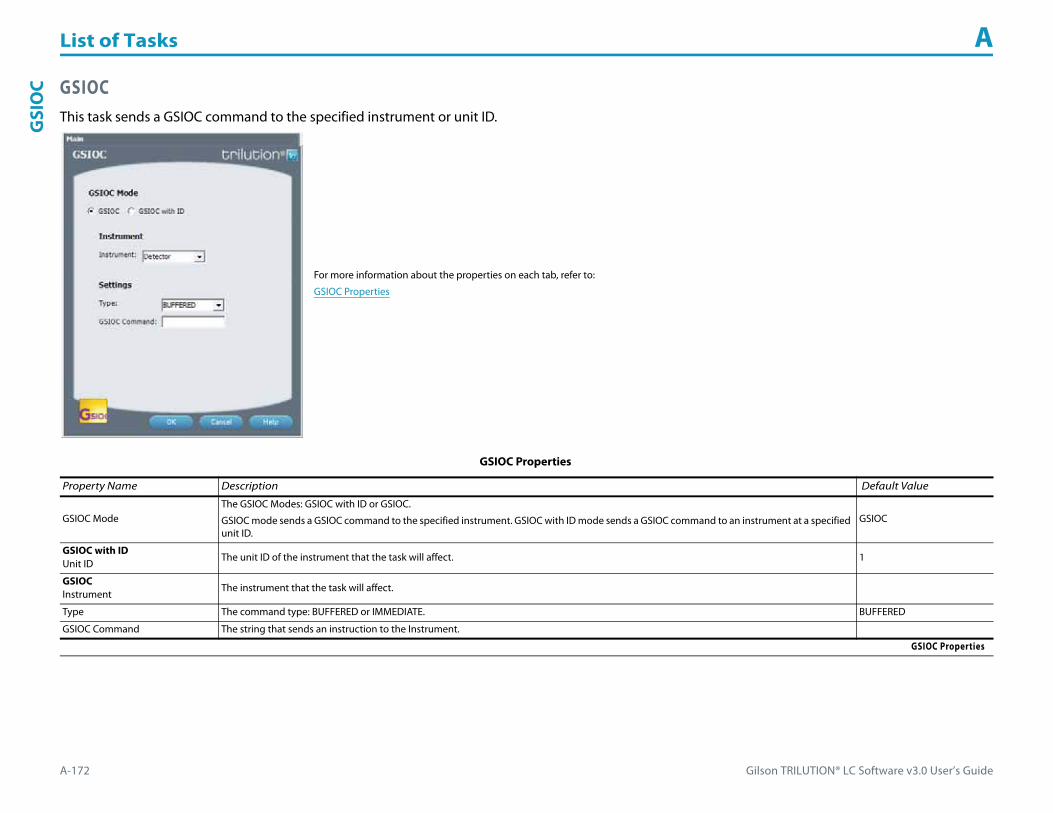
List of Tasks A
A-172 Gilson TRILUTION® LC Software v3.0 User’s Guide
GSI
OC GSIOC
This task sends a GSIOC command to the specified instrument or unit ID.
For more information about the properties on each tab, refer to:
GSIOC Properties
GSIOC Properties
Property Name Description Default Value
GSIOC ModeThe GSIOC Modes: GSIOC with ID or GSIOC.
GSIOC mode sends a GSIOC command to the specified instrument. GSIOC with ID mode sends a GSIOC command to an instrument at a specified unit ID.
GSIOC
GSIOC with IDUnit ID
The unit ID of the instrument that the task will affect. 1
GSIOCInstrument
The instrument that the task will affect.
Type The command type: BUFFERED or IMMEDIATE. BUFFERED
GSIOC Command The string that sends an instruction to the Instrument.
GSIOC Properties

Gilson TRILUTION® LC Software v3.0 User’s Guide A-173
List of Tasks AG
X Add D
iluent
GX Add DiluentThis task aspirates the specified liquid (Diluent Source) from the reservoir or the probe and then dispenses to the wells of the sample zone and then mixes with liquid or air.
For more information about the properties on each tab, refer to:
GX Add Diluent Properties - Main
GX Add Diluent Properties - Advanced
GX Add Diluent Properties - Mixing
GX Add Diluent Properties - Rinsing
GX Add Diluent - Sequence of Steps
GX Add Diluent Properties - Main
Property Name Description Default Value
Liquid Handler The liquid handler that the task will affect. Liquid Handler
Pump The pump that the task will affect. Liquid Handler
Solvent Valve PositionThe desired position of the solvent selection valve on the GX Solvent System. Valid range is 1–6.
Note: The position designated for waste cannot be used for a solvent.2
GX Add Diluent Properties - Main (Page 1 of 2)

List of Tasks A
A-174 Gilson TRILUTION® LC Software v3.0 User’s Guide
GX
Add
Dilu
ent
Diluent Source Select Reservoir or Tray. Reservoir
ReservoirSample Zone
The zone to which the Diluent Volume is delivered. Sample Zone
ReservoirSample Well
Enter the well number in the Sample Zone. 0
TrayDiluent Zone
When Tray is selected; the zone from which the Diluent Volume is aspirated. Sample Zone
TrayDiluent Well
When Tray is selected; enter the well number in the Diluent Zone. 0
TraySample Zone
The zone to which the Diluent Volume is delivered. Sample Zone
TraySample Well
Enter the well number in the Sample Zone. 0
Air Gap Volume The quantity of an air gap. 50 μL
Diluent Volume The quantity of liquid used to dilute the sample volume in the Sample Well in the Sample Zone. 0 μL
GX Add Diluent Properties - Advanced
Property Name Description Default Value
Aspirate Flow Rate The speed at which liquid volumes move into the probe. 1.5 mL/min
Dispense Flow Rate The speed at which liquid volumes move out of the probe. 3 mL/min
Air Gap Flow Rate The speed at which the Air Gap Volume moves into the probe. 1 mL/min
Aspirate Z Option
One of six defined reference points used when aspirating the Diluent Volume from the bed:Auto Calculate: Places probe into well and at the liquid level using initial volume from the sample list and well dimensions from the bed layout; accepts a positive (+) or negative (-) value for the Aspirate Z Offset.Absolute Value: Moves the probe to the Z-value entered; if 0 is entered for the Aspirate Z Offset, the probe will move to the bed bottom (no safety factor incorporated).Tube Bottom: Moves the probe to the well bottom as defined by the bed layout; accepts only positive Aspirate Z Offset value to move up from the bottom.Top: Moves probe to the top of their Z-travel range; accepts only a negative (-) value for the Aspirate Z Offset.Tube Top: Moves the probe to the top of the well as defined by the bed layout; accepts a positive (+) or negative (-) value for the Aspirate Z Offset.Z Adjust: Moves the probe from the current position up (positive value) or down (negative value).
Tube Bottom
Aspirate Z Offset When Tray is selected, the distance up (when a positive number is entered) or down (when a negative number is entered) from a reference point defined by the Aspirate Z Option used when aspirating the Diluent Volume from the bed. 2 mm
Aspirate LLFWhen Tray is selected, the probe will follow the liquid down as it is aspirated from the Diluent Zone. The Aspirate Z Option must be set to AUTO CALCULATE and initial volumes must be set in the sample list to use this option.
When cleared, the probe will not follow the liquid down as it is aspirated from the Diluent Zone.Cleared
GX Add Diluent Properties - Advanced (Page 1 of 2)
GX Add Diluent Properties - Main (Continued)
Property Name Description Default Value
GX Add Diluent Properties - Main (Page 2 of 2)

Gilson TRILUTION® LC Software v3.0 User’s Guide A-175
List of Tasks AG
X Add D
iluentDispense Z Option
One of six defined reference points used when delivering the Diluent Volume to the bed:Auto Calculate: laces probe into well and at the liquid level using initial volume from the sample list and well dimensions from the bed layout; accepts a positive (+) or negative (-) value for the Dispense Z Offset.Absolute Value: Moves the probe to the Z-value entered; if 0 is entered for the Dispense Z Offset, the probe will move to the bed bottom (no safety factor incorporated).Tube Bottom: Moves the probe to the well bottom as defined by the bed layout; accepts only positive Dispense Z Offset value to move up from the bottom.Top: Moves probe to the top of their Z-travel range; accepts only a negative (-) value for the Dispense Z Offset.Tube Top: Moves the probe to the top of the well as defined by the bed layout; accepts a positive (+) or negative (-) value for the Dispense Z Offset.Z Adjust: Moves the probe from the current position up (positive value) or down (negative value).
Tube Bottom
Dispense Z Offset The distance up (when a positive number is entered) or down (when a negative number is entered) from a reference point defined by the Dispense Z Option used when delivering the Diluent Volume to the bed. 2 mm
Dispense LLFWhen selected, the probe will follow the liquid up as it is delivered to the Sample Zone. The Dispense Z Option must be set to AUTO CALCULATE and initial volumes must be set in the sample list to use this option.
When cleared, the probe will not follow the liquid up as it is delivered to the Sample Zone.Cleared
GX Add Diluent Properties - Mixing
Property Name Description Default Value
Mixing Properties Select Mix with Liquid or Mix with Air to perform a mix of the Diluent Volume with the Sample Volume. Select No Mix for no mixing. No Mix
Mix with LiquidNumber of Cycles
Type the number of times the task should repeat the commands related to mixing. 2
Mix with LiquidMixing Volume
The quantity of liquid used as part of a mixing process. 0 μL
Mix with LiquidMix Aspirate Flow Rate
The speed at which volumes move into the probe during the mixing process. 1 mL/min
Mix with LiquidMix Dispense Flow Rate
The speed at which volumes move out of the probe during the mixing process. 5 mL/min
Mix with LiquidMix Aspirate Z Option
One of six defined reference points used when aspirating the Mixing Volume from the bed:Auto Calculate: Places probe into well and at the liquid level using initial volume from the sample list and well dimensions from the bed layout; accepts a positive (+) or negative (-) value for the Mix Aspirate Z Offset.Absolute Value: Moves the probe to the Z-value entered; if 0 is entered for the Mix Aspirate Z Offset, the probe will move to the bed bottom (no safety factor incorporated).Tube Bottom: Moves the probe to the well bottom as defined by the bed layout; accepts only positive Mix Aspirate Z Offset value to move up from the bottom.Top: Moves probe to the top of their Z-travel range; accepts only a negative (-) value for the Mix Aspirate Z Offset.Tube Top: Moves the probe to the top of the well as defined by the bed layout; accepts a positive (+) or negative (-) value for the Mix Aspirate Z Offset.Z Adjust: Moves the probe from the current position up (positive value) or down (negative value).
Tube Bottom
Mix with LiquidMix Aspirate Z Offset
The distance up (when a positive number is entered) or down (when a negative number is entered) from a reference point defined by the Mix Aspirate Z Option used when aspirating the Mixing Volume from the bed. 2 mm
GX Add Diluent Properties - Mixing (Page 1 of 2)
GX Add Diluent Properties - Advanced (Continued)
Property Name Description Default Value
GX Add Diluent Properties - Advanced (Page 2 of 2)
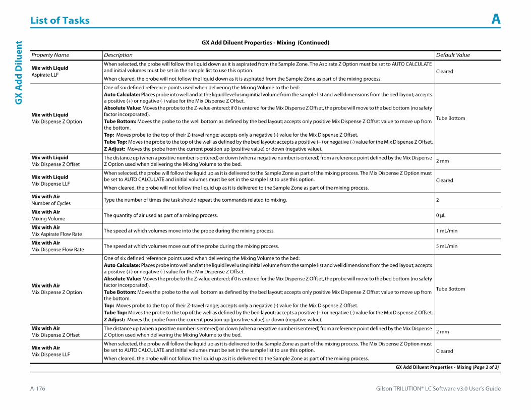
List of Tasks A
A-176 Gilson TRILUTION® LC Software v3.0 User’s Guide
GX
Add
Dilu
ent
Mix with LiquidAspirate LLF
When selected, the probe will follow the liquid down as it is aspirated from the Sample Zone. The Aspirate Z Option must be set to AUTO CALCULATE and initial volumes must be set in the sample list to use this option.
When cleared, the probe will not follow the liquid down as it is aspirated from the Sample Zone as part of the mixing process.Cleared
Mix with LiquidMix Dispense Z Option
One of six defined reference points used when delivering the Mixing Volume to the bed:Auto Calculate: Places probe into well and at the liquid level using initial volume from the sample list and well dimensions from the bed layout; accepts a positive (+) or negative (-) value for the Mix Dispense Z Offset.Absolute Value: Moves the probe to the Z-value entered; if 0 is entered for the Mix Dispense Z Offset, the probe will move to the bed bottom (no safety factor incorporated).Tube Bottom: Moves the probe to the well bottom as defined by the bed layout; accepts only positive Mix Dispense Z Offset value to move up from the bottom.Top: Moves probe to the top of their Z-travel range; accepts only a negative (-) value for the Mix Dispense Z Offset.Tube Top: Moves the probe to the top of the well as defined by the bed layout; accepts a positive (+) or negative (-) value for the Mix Dispense Z Offset.Z Adjust: Moves the probe from the current position up (positive value) or down (negative value).
Tube Bottom
Mix with LiquidMix Dispense Z Offset
The distance up (when a positive number is entered) or down (when a negative number is entered) from a reference point defined by the Mix Dispense Z Option used when delivering the Mixing Volume to the bed. 2 mm
Mix with LiquidMix Dispense LLF
When selected, the probe will follow the liquid up as it is delivered to the Sample Zone as part of the mixing process. The Mix Dispense Z Option must be set to AUTO CALCULATE and initial volumes must be set in the sample list to use this option.
When cleared, the probe will not follow the liquid up as it is delivered to the Sample Zone as part of the mixing process.Cleared
Mix with AirNumber of Cycles
Type the number of times the task should repeat the commands related to mixing. 2
Mix with AirMixing Volume
The quantity of air used as part of a mixing process. 0 μL
Mix with AirMix Aspirate Flow Rate
The speed at which volumes move into the probe during the mixing process. 1 mL/min
Mix with AirMix Dispense Flow Rate
The speed at which volumes move out of the probe during the mixing process. 5 mL/min
Mix with AirMix Dispense Z Option
One of six defined reference points used when delivering the Mixing Volume to the bed:Auto Calculate: Places probe into well and at the liquid level using initial volume from the sample list and well dimensions from the bed layout; accepts a positive (+) or negative (-) value for the Mix Dispense Z Offset.Absolute Value: Moves the probe to the Z-value entered; if 0 is entered for the Mix Dispense Z Offset, the probe will move to the bed bottom (no safety factor incorporated).Tube Bottom: Moves the probe to the well bottom as defined by the bed layout; accepts only positive Mix Dispense Z Offset value to move up from the bottom.Top: Moves probe to the top of their Z-travel range; accepts only a negative (-) value for the Mix Dispense Z Offset.Tube Top: Moves the probe to the top of the well as defined by the bed layout; accepts a positive (+) or negative (-) value for the Mix Dispense Z Offset.Z Adjust: Moves the probe from the current position up (positive value) or down (negative value).
Tube Bottom
Mix with AirMix Dispense Z Offset
The distance up (when a positive number is entered) or down (when a negative number is entered) from a reference point defined by the Mix Dispense Z Option used when delivering the Mixing Volume to the bed. 2 mm
Mix with AirMix Dispense LLF
When selected, the probe will follow the liquid up as it is delivered to the Sample Zone as part of the mixing process. The Mix Dispense Z Option must be set to AUTO CALCULATE and initial volumes must be set in the sample list to use this option.
When cleared, the probe will not follow the liquid up as it is delivered to the Sample Zone as part of the mixing process.Cleared
GX Add Diluent Properties - Mixing (Continued)
Property Name Description Default Value
GX Add Diluent Properties - Mixing (Page 2 of 2)

Gilson TRILUTION® LC Software v3.0 User’s Guide A-177
List of Tasks AG
X Add D
iluent
GX Add Diluent Properties - Rinsing For information about rinse positions, refer to Appendix B, Rinse Locations
Property Name Description Default Value
Inside Rinse Zone The zone to which the Inside Rinse Volume is delivered. Inside Rinse
Inside Rinse Well Enter the well number in the Inside Rinse Zone. 1
Inside Rinse Volume The quantity of liquid used to rinse the inside of the probe. 1000 μL
Inside Rinse Flow Rate The speed at which the Inside Rinse Volume moves out of the probe and into the inside rinse position in the rinse station. 5 mL/min
Inside Rinse Z Option
One of six defined reference points used when performing the inside rinse:Auto Calculate: Places probe into well and at the liquid level using initial volume from the sample list and well dimensions from the bed layout; accepts a positive (+) or negative (-) value for the Inside Rinse Z Offset.Absolute Value: Moves the probe to the Z-value entered; if 0 is entered for the Inside Rinse Z Offset, the probe will move to the bed bottom (no safety factor incorporated).Tube Bottom: Moves the probe to the well bottom as defined by the bed layout; accepts only positive Inside Rinse Z Offset values to move up from the bottom.Top: Moves probe to the top of their Z-travel range; accepts only a negative (-) value for the Inside Rinse Z Offset.Tube Top: Moves the probe to the top of the well as defined by the bed layout; accepts a positive (+) or negative (-) value for the Inside Rinse Z Offset.Z Adjust: Moves the probe from the current position up (positive value) or down (negative value).
Tube Top
Inside Rinse Z Offset The distance up (when a positive number is entered) or down (when a negative number is entered) from a reference point defined by the Inside Rinse Z Option for rinsing the probe at the inside rinse position in the rinse station. -7 mm
Outside Rinse Zone The zone to which the Outside Rinse Volume is delivered. Outside Rinse
Number of Rinse Stations Select the number of rinse stations to be used when performing the outside rinse. Valid range is 1–5. 1
Rinse Well 1 Solvent Valve Position
The desired position of the solvent selection valve on the GX Solvent System during the outside rinse at rinse station 1. Valid range is 1–6.
The position designated for waste cannot be used for a solvent.2
Rinse Well 2 Solvent Valve Position
The desired position of the solvent selection valve on the GX Solvent System during the outside rinse at rinse station 2. Valid range is 1–6.
The position designated for waste cannot be used for a solvent.2
Rinse Well 3 Solvent Valve Position
The desired position of the solvent selection valve on the GX Solvent System during the outside rinse at rinse station 3. Valid range is 1–6.
The position designated for waste cannot be used for a solvent.2
Rinse Well 4 Solvent Valve Position
The desired position of the solvent selection valve on the GX Solvent System during the outside rinse at rinse station 4. Valid range is 1–6.
The position designated for waste cannot be used for a solvent.2
Rinse Well 5 Solvent Valve Position
The desired position of the solvent selection valve on the GX Solvent System during the outside rinse at rinse station 5. Valid range is 1–6.
The position designated for waste cannot be used for a solvent.2
Outside Rinse Volume The quantity of liquid used to rinse the outside of the probe. 2000 μL
Outside Rinse Flow Rate The speed at which the Outside Rinse Volume moves out of the probe and into the outside rinse position in the rinse station. 5 mL/min
GX Add Diluent Properties - Rinsing (Page 1 of 2)

List of Tasks A
A-178 Gilson TRILUTION® LC Software v3.0 User’s Guide
GX
Add
Dilu
ent
GX Add Diluent - Sequence of Steps1 Aspirate2 Dispense3 Mix with Liquid (Optional)4 Mix with Air (Optional)5 Inside Rinse6 Outside Rinse
Outside Rinse Z Option
One of six defined reference points used when performing the outside rinse:Auto Calculate: Places probe into well and at the liquid level using initial volume from the sample list and well dimensions from the bed layout; accepts a positive (+) or negative (-) value for the Outside Rinse Z Offset.Absolute Value: Moves the probe to the Z-value entered; if 0 is entered for the Outside Rinse Z Offset, the probe will move to the bed bottom (no safety factor incorporated).Tube Bottom: Moves the probe to the well bottom as defined by the bed layout; accepts only positive Outside Rinse Z Offset values to move up from the bottom.Top: Moves probe to the top of their Z-travel range; accepts only a negative (-) value for the Outside Rinse Z Offset.Tube Top: Moves the probe to the top of the well as defined by the bed layout; accepts a positive (+) or negative (-) value for the Outside Rinse Z Offset.Z Adjust: Moves the probe from the current position up (positive value) or down (negative value).
Tube Bottom
Outside Rinse Z Offset The distance up (when a positive number is entered) or down (when a negative number is entered) from a reference point defined by the Outside Rinse Z Option for rinsing the probe at the outside rinse position in the rinse station. 2 mm
Rinse Pump The rinse pump that will be used for the flowing outside rinse. Select 1 if the rinse pump is wired to Output 1 and 24V Output 1 or select 2 if the rinse pump is wired to Output 2 and 24V Output 2. 1
Rinse Pump Speed Select HIGH, LOW, or OFF. OFF
GX Add Diluent Properties - Rinsing (Continued)For information about rinse positions, refer to Appendix B, Rinse Locations
Property Name Description Default Value
GX Add Diluent Properties - Rinsing (Page 2 of 2)

Gilson TRILUTION® LC Software v3.0 User’s Guide A-179
List of Tasks AG
X Add D
iluent
Aspirate1 Move Z to Z Safe Height.
Probe1 Move to Diluent Well in Diluent Zone.2 Switch solvent valve to waste and aspirate Air Gap Volume at Air Gap Flow Rate.3 Lower probe to Aspirate Z Option and Aspirate Z Offset.4 Aspirate Diluent Volume at Aspirate Flow Rate.5 Move Z to Z Safe Height.
Dispense
Reservoir1 Move to Sample Well in Sample Zone.2 Lower probe to Dispense Z Option and Dispense Z Offset.3 Switch solvent valve to Solvent Valve Position and dispense Diluent Volume at Dispense Flow Rate.4 Move Z to Z Safe Height.
Probe
Air Gap Volume = 0
1 Move to Sample Well in Sample Zone.2 Lower probe to Dispense Z Option and Dispense Z Offset.3 Switch solvent valve to Solvent Valve Position and dispense Diluent Volume at Dispense Flow Rate4 Move Z to Z Safe Height.
Air Gap Volume > 0
1 Move to Sample Well in Sample Zone.2 Lower probe to Dispense Z Option and Dispense Z Offset.3 Switch solvent valve to Solvent Valve Position and dispense Diluent Volume + 1/2 Air Gap Volume at Dispense Flow Rate4 Move Z to Z Safe Height.5 Move to Inside Rinse Well in Inside Rinse Zone.6 Lower probe to Inside Rinse Z Option and Inside Rinse Z Offset.7 Dispense 1/2 Air Gap Volume at Inside Rinse Flow Rate.8 Move Z to Z Safe Height.

List of Tasks A
A-180 Gilson TRILUTION® LC Software v3.0 User’s Guide
GX
Add
Dilu
ent Mix with Liquid (Optional)
If Mix with Liquid = TRUE
1 Move Z to Z Safe Height.2 Switch solvent valve to waste and aspirate Air Gap Volume at Air Gap Flow Rate.3 Move to Sample Well in Sample Zone.4 Lower probe to Mix Aspirate Z Option and Mix Aspirate Z Offset.5 Aspirate Mixing Volume at Mix Aspirate Flow Rate.6 Lower probe to Mix Dispense Z Option and Mix Dispense Z Offset.7 Switch solvent valve to Solvent Valve Position and dispense Mixing Volume at Mix Dispense Flow Rate.8 Repeat steps 4–7 for Number of Cycles.9 Move Z to Z Safe Height.
Mix with Air (Optional)
If Mix with Air = TRUE
1 Move Z to Z Safe Height.2 Move to Sample Well in Sample Zone.3 Move Z to Z Safe Height.4 Switch solvent valve to waste and aspirate Air Gap Volume (first cycle only) and Mixing Volume at Mix Aspirate Flow Rate.5 Lower probe to Mix Dispense Z Option and Mix Dispense Z Offset.6 Switch solvent valve to Solvent Valve Position and dispense Mixing Volume at Mix Dispense Flow Rate.7 Repeat steps 3–6 for Number of Cycles.8 Move Z to Z Safe Height.
Inside Rinse1 Move Z to Z Safe Height.2 Move to Inside Rinse Well in Inside Rinse Zone.3 Lower probe into well to Inside Rinse Z Option and Inside Rinse Z Offset.4 Switch solvent valve to Solvent Valve Position and dispense volume held by transfer tubing at Inside Rinse Flow Rate.5 Dispense Inside Rinse Volume at Inside Rinse Flow Rate.6 Move Z to Z Safe Height.

Gilson TRILUTION® LC Software v3.0 User’s Guide A-181
List of Tasks AG
X Add D
iluent
Outside Rinse1 Move Z to Z Safe Height.2 Move to rinse station/well 1 in Outside Rinse Zone.3 Lower probe into well to Outside Rinse Z Option and Outside Rinse Z Offset.4 Switch Rinse Pump on at Rinse Pump Speed.5 Switch solvent valve to Rinse Well 1 Solvent Valve Position and dispense Outside Rinse Volume at Outside Rinse Flow Rate. If the current solvent valve position
is not the same as the previous solvent valve position, dispense Outside Rinse Volume + 2000 uL + Transfer Tubing volume.6 Switch Rinse Pump off.7 Move Z to Z Safe Height.8 Repeat steps 2–7 for the Number of Rinse Stations, incrementing the rinse station/well for each rinse station.

List of Tasks A
A-182 Gilson TRILUTION® LC Software v3.0 User’s Guide
GX
Dilu
te GX DiluteThis task aspirates the specified amount of diluent volume from the reservoir or the bed and then dispenses to result. The task next aspirates sample from the wells of the sample zone and then dispenses again to the result zone. Finally, a mix with liquid or air is performed in the wells of the result zone.
For more information about the properties on each tab, refer to:
GX Dilute Properties - Main
GX Dilute Properties - Advanced
GX Dilute Properties - Mixing
GX Dilute Properties - Rinsing
GX Dilute - Sequence of Steps
GX Dilute Properties - Main
Property Name Description Default Value
Liquid Handler The liquid handler that the task will affect. Liquid Handler
Pump The pump that the task will affect. Liquid Handler
Solvent Valve PositionThe desired position of the solvent selection valve on the GX Solvent System. Valid range is 1–6.
The position designated for waste cannot be used for a solvent.2
GX Dilute Properties - Main (Page 1 of 2)
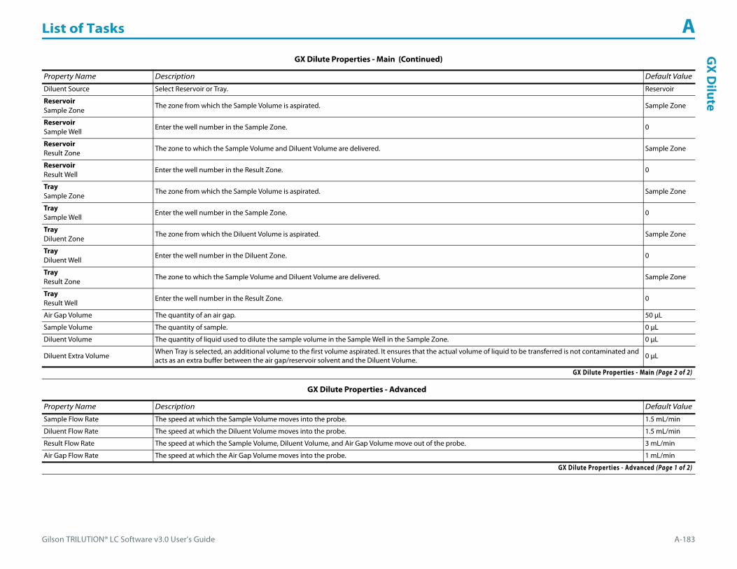
Gilson TRILUTION® LC Software v3.0 User’s Guide A-183
List of Tasks AG
X Dilute
Diluent Source Select Reservoir or Tray. Reservoir
ReservoirSample Zone
The zone from which the Sample Volume is aspirated. Sample Zone
ReservoirSample Well
Enter the well number in the Sample Zone. 0
ReservoirResult Zone
The zone to which the Sample Volume and Diluent Volume are delivered. Sample Zone
ReservoirResult Well
Enter the well number in the Result Zone. 0
TraySample Zone
The zone from which the Sample Volume is aspirated. Sample Zone
TraySample Well
Enter the well number in the Sample Zone. 0
TrayDiluent Zone
The zone from which the Diluent Volume is aspirated. Sample Zone
TrayDiluent Well
Enter the well number in the Diluent Zone. 0
TrayResult Zone
The zone to which the Sample Volume and Diluent Volume are delivered. Sample Zone
TrayResult Well
Enter the well number in the Result Zone. 0
Air Gap Volume The quantity of an air gap. 50 μL
Sample Volume The quantity of sample. 0 μL
Diluent Volume The quantity of liquid used to dilute the sample volume in the Sample Well in the Sample Zone. 0 μL
Diluent Extra Volume When Tray is selected, an additional volume to the first volume aspirated. It ensures that the actual volume of liquid to be transferred is not contaminated and acts as an extra buffer between the air gap/reservoir solvent and the Diluent Volume. 0 μL
GX Dilute Properties - Advanced
Property Name Description Default Value
Sample Flow Rate The speed at which the Sample Volume moves into the probe. 1.5 mL/min
Diluent Flow Rate The speed at which the Diluent Volume moves into the probe. 1.5 mL/min
Result Flow Rate The speed at which the Sample Volume, Diluent Volume, and Air Gap Volume move out of the probe. 3 mL/min
Air Gap Flow Rate The speed at which the Air Gap Volume moves into the probe. 1 mL/min
GX Dilute Properties - Advanced (Page 1 of 2)
GX Dilute Properties - Main (Continued)
Property Name Description Default Value
GX Dilute Properties - Main (Page 2 of 2)
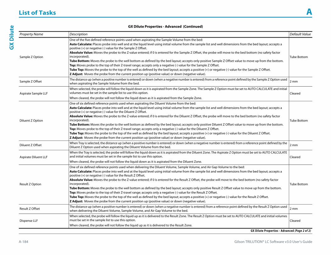
List of Tasks A
A-184 Gilson TRILUTION® LC Software v3.0 User’s Guide
GX
Dilu
te
Sample Z Option
One of the five defined reference points used when aspirating the Sample Volume from the bed:Auto Calculate: Places probe into well and at the liquid level using initial volume from the sample list and well dimensions from the bed layout; accepts a positive (+) or negative (-) value for the Sample Z Offset.Absolute Value: Moves the probe to the Z-value entered; if 0 is entered for the Sample Z Offset, the probe will move to the bed bottom (no safety factor incorporated).Tube Bottom: Moves the probe to the well bottom as defined by the bed layout; accepts only positive Sample Z Offset value to move up from the bottom.Top: Moves probe to the top of their Z-travel range; accepts only a negative (-) value for the Sample Z Offset.Tube Top: Moves the probe to the top of the well as defined by the bed layout; accepts a positive (+) or negative (-) value for the Sample Z Offset.Z Adjust: Moves the probe from the current position up (positive value) or down (negative value).
Tube Bottom
Sample Z Offset The distance up (when a positive number is entered) or down (when a negative number is entered) from a reference point defined by the Sample Z Option used when aspirating the Sample Volume from the bed. 2 mm
Aspirate Sample LLFWhen selected, the probe will follow the liquid down as it is aspirated from the Sample Zone. The Sample Z Option must be set to AUTO CALCULATE and initial volumes must be set in the sample list to use this option.
When cleared, the probe will not follow the liquid down as it is aspirated from the Sample Zone.Cleared
Diluent Z Option
One of six defined reference points used when aspirating the Diluent Volume from the bed:Auto Calculate: Places probe into well and at the liquid level using initial volume from the sample list and well dimensions from the bed layout; accepts a positive (+) or negative (-) value for the Diluent Z Offset.Absolute Value: Moves the probe to the Z-value entered; if 0 is entered for the Diluent Z Offset, the probe will move to the bed bottom (no safety factor incorporated).Tube Bottom: Moves the probe to the well bottom as defined by the bed layout; accepts only positive Diluent Z Offset value to move up from the bottom.Top: Moves probe to the top of their Z-travel range; accepts only a negative (-) value for the Diluent Z Offset.Tube Top: Moves the probe to the top of the well as defined by the bed layout; accepts a positive (+) or negative (-) value for the Diluent Z Offset.Z Adjust: Moves the probe from the current position up (positive value) or down (negative value).
Tube Bottom
Diluent Z Offset When Tray is selected, the distance up (when a positive number is entered) or down (when a negative number is entered) from a reference point defined by the Diluent Z Option used when aspirating the Diluent Volume from the bed. 2 mm
Aspirate Diluent LLFWhen the Tray is selected, the probe will follow the liquid down as it is aspirated from the Diluent Zone. The Aspirate Z Option must be set to AUTO CALCULATE and initial volumes must be set in the sample list to use this option.
When cleared, the probe will not follow the liquid down as it is aspirated from the Diluent Zone.Cleared
Result Z Option
One of six defined reference points used when delivering the Diluent Volume, Sample Volume, and Air Gap Volume to the bed:Auto Calculate: Places probe into well and at the liquid level using initial volume from the sample list and well dimensions from the bed layout; accepts a positive (+) or negative (-) value for the Result Z Offset.Absolute Value: Moves the probe to the Z-value entered; if 0 is entered for the Result Z Offset, the probe will move to the bed bottom (no safety factor incorporated).Tube Bottom: Moves the probe to the well bottom as defined by the bed layout; accepts only positive Result Z Offset value to move up from the bottom.Top: Moves probe to the top of their Z-travel range; accepts only a negative (-) value for the Result Z Offset.Tube Top: Moves the probe to the top of the well as defined by the bed layout; accepts a positive (+) or negative (-) value for the Result Z Offset.Z Adjust: Moves the probe from the current position up (positive value) or down (negative value).
Tube Bottom
Result Z Offset The distance up (when a positive number is entered) or down (when a negative number is entered) from a reference point defined by the Result Z Option used when delivering the Diluent Volume, Sample Volume, and Air Gap Volume to the bed. 2 mm
Dispense LLFWhen selected, the probe will follow the liquid up as it is delivered to the Result Zone. The Result Z Option must be set to AUTO CALCULATE and initial volumes must be set in the sample list to use this option.
When cleared, the probe will not follow the liquid up as it is delivered to the Result Zone.Cleared
GX Dilute Properties - Advanced (Continued)
Property Name Description Default Value
GX Dilute Properties - Advanced (Page 2 of 2)

Gilson TRILUTION® LC Software v3.0 User’s Guide A-185
List of Tasks AG
X Dilute
GX Dilute Properties - Mixing
Property Name Description Default Value
Mixing Properties Select Mix with Liquid or Mix with Air to perform a mix of the Diluent Volume with the Sample Volume. Select No Mix for no mixing. No Mix
Mix with LiquidNumber of Cycles
Type the number of times the task should repeat the commands related to mixing. 2
Mix with LiquidMixing Volume
The quantity of liquid used as part of a mixing process. 0 μL
Mix with LiquidMix Aspirate Flow Rate
The speed at which volumes move into the probe during the mixing process. 1 mL/min
Mix with LiquidMix Dispense Flow Rate
The speed at which volumes move out of the probe during the mixing process. 5 mL/min
Mix with LiquidMix Aspirate Z Option
One of six defined reference points used when aspirating the Mixing Volume from the bed:Auto Calculate: Places probe into well and at the liquid level using initial volume from the sample list and well dimensions from the bed layout; accepts a positive (+) or negative (-) value for the Mix Aspirate Z Offset.Absolute Value: Moves the probe to the Z-value entered; if 0 is entered for the Mix Aspirate Z Offset, the probe will move to the bed bottom (no safety factor incorporated).Tube Bottom: Moves the probe to the well bottom as defined by the bed layout; accepts only positive Mix Aspirate Z Offset value to move up from the bottom.Top: Moves probe to the top of their Z-travel range; accepts only a negative (-) value for the Mix Aspirate Z Offset.Tube Top: Moves the probe to the top of the well as defined by the bed layout; accepts a positive (+) or negative (-) value for the Mix Aspirate Z Offset.Z Adjust: Moves the probe from the current position up (positive value) or down (negative value).
Tube Bottom
Mix with LiquidMix Aspirate Z Offset
The distance up (when a positive number is entered) or down (when a negative number is entered) from a reference point defined by the Mix Aspirate Z Option used when aspirating the Mixing Volume from the bed. 2 mm
Mix with LiquidAspirate LLF
When selected, the probe will follow the liquid down as it is aspirated from the Diluent Zone. The Aspirate Z Option must be set to AUTO CALCULATE and initial volumes must be set in the sample list to use this option.
When cleared, the probe will not follow the liquid down as it is aspirated from the Diluent Zone.Cleared
Mix with LiquidMix Dispense Z Option
One of six defined reference points used when delivering the Mixing Volume to the bed:Auto Calculate: Places probe into well and at the liquid level using initial volume from the sample list and well dimensions from the bed layout; accepts a positive (+) or negative (-) value for the Mix Dispense Z Offset.Absolute Value: Moves the probe to the Z-value entered; if 0 is entered for the Mix Dispense Z Offset, the probe will move to the bed bottom (no safety factor incorporated).Tube Bottom: Moves the probe to the well bottom as defined by the bed layout; accepts only positive Mix Dispense Z Offset value to move up from the bottom.Top: Moves probe to the top of their Z-travel range; accepts only a negative (-) value for the Mix Dispense Z Offset.Tube Top: Moves the probe to the top of the well as defined by the bed layout; accepts a positive (+) or negative (-) value for the Mix Dispense Z Offset.Z Adjust: Moves the probe from the current position up (positive value) or down (negative value).
Tube Bottom
Mix with LiquidMix Dispense Z Offset
The distance up (when a positive number is entered) or down (when a negative number is entered) from a reference point defined by the Mix Dispense Z Option used when delivering the Mixing Volume to the bed. 2 mm
Mix with LiquidMix Dispense LLF
When selected, the probe will follow the liquid up as it is delivered to the Sample Zone as part of the mixing process. The Mix Dispense Z Option must be set to AUTO CALCULATE and initial volumes must be set in the sample list to use this option.
When cleared, the probe will not follow the liquid up as it is delivered to the Sample Zone as part of the mixing process.Cleared
Mix with AirNumber of Cycles
Type the number of times the task should repeat the commands related to mixing. 2
GX Dilute Properties - Mixing (Page 1 of 2)

List of Tasks A
A-186 Gilson TRILUTION® LC Software v3.0 User’s Guide
GX
Dilu
te
Mix with AirMixing Volume
The quantity of air used as part of a mixing process. 0 μL
Mix with AirMix Aspirate Flow Rate
The speed at which volumes move into the probe during the mixing process. 1 mL/min
Mix with AirMix Dispense Flow Rate
The speed at which volumes move out of the probe during the mixing process. 5 mL/min
Mix with AirMix Dispense Z Option
One of six defined reference points used when delivering the Mixing Volume to the bed:Auto Calculate: Places probe into well and at the liquid level using initial volume from the sample list and well dimensions from the bed layout; accepts a positive (+) or negative (-) value for the Mix Dispense Z Offset.Absolute Value: Moves the probe to the Z-value entered; if 0 is entered for the Mix Dispense Z Offset, the probe will move to the bed bottom (no safety factor incorporated).Tube Bottom: Moves the probe to the well bottom as defined by the bed layout; accepts only positive Mix Dispense Z Offset value to move up from the bottom.Top: Moves probe to the top of their Z-travel range; accepts only a negative (-) value for the Mix Dispense Z Offset.Tube Top: Moves the probe to the top of the well as defined by the bed layout; accepts a positive (+) or negative (-) value for the Mix Dispense Z Offset.Z Adjust: Moves the probe from the current position up (positive value) or down (negative value).
Tube Bottom
Mix with AirMix Dispense Z Offset
The distance up (when a positive number is entered) or down (when a negative number is entered) from a reference point defined by the Mix Dispense Z Option used when delivering the Mixing Volume to the bed. 2 mm
Mix with AirMix Dispense LLF
When selected, the probe will follow the liquid up as it is delivered to the Sample Zone as part of the mixing process. The Mix Dispense Z Option must be set to AUTO CALCULATE and initial volumes must be set in the sample list to use this option.
When cleared, the probe will not follow the liquid up as it is delivered to the Sample Zone as part of the mixing process.Cleared
GX Dilute Properties - Rinsing For information about rinse positions, refer to Appendix B, Rinse Locations.
Property Name Description Default Value
Inside Rinse Zone The zone to which the Inside Rinse Volume is delivered. Inside Rinse
Inside Rinse Well Enter the well number in the Inside Rinse Zone. 1
Inside Rinse Volume The quantity of liquid used to rinse the inside of the probe. 1000 μL
Inside Rinse Flow Rate The speed at which the Inside Rinse Volume moves out of the probe and into the inside rinse position in the rinse station. 5 mL/min
Inside Rinse Z Option
One of six defined reference points used when performing the inside rinse:Auto Calculate: Places probe into well and at the liquid level using initial volume from the sample list and well dimensions from the bed layout; accepts a positive (+) or negative (-) value for the Inside Rinse Z Offset.Absolute Value: Moves the probe to the Z-value entered; if 0 is entered, probe will move to the bed bottom (no safety factor incorporated).Tube Bottom: Moves the probe to the well bottom as defined by the bed layout; accepts only positive Inside Rinse Z Offset values to move up from the bottom.Top: Moves probe to the top of their Z-travel range; accepts only a negative (-) value for the Inside Rinse Z Offset.Tube Top: Moves the probe to the top of the well as defined by the bed layout; accepts a positive (+) or negative (-) value for the Inside Rinse Z Offset.Z Adjust: Moves the probe from the current position up (positive value) or down (negative value).
Tube Top
Inside Rinse Z Offset The distance up (when a positive number is entered) or down (when a negative number is entered) from a reference point defined by the Inside Rinse Z Option for rinsing the probe at the inside rinse position in the rinse station. -7 mm
GX Dilute Properties - Rinsing (Page 1 of 2)
GX Dilute Properties - Mixing (Continued)
Property Name Description Default Value
GX Dilute Properties - Mixing (Page 2 of 2)

Gilson TRILUTION® LC Software v3.0 User’s Guide A-187
List of Tasks AG
X DiluteOutside Rinse Zone The zone to which the Outside Rinse Volume is delivered. Outside Rinse
Number of Rinse Stations Select the number of rinse stations to be used when performing the outside rinse. Valid range is 1–5. 1
Rinse Well 1 Solvent Valve PositionThe desired position of the solvent selection valve on the GX Solvent System during the outside rinse at rinse station 1. Valid range is 1–6.
The position designated for waste cannot be used for a solvent.2
Rinse Well 2 Solvent Valve PositionThe desired position of the solvent selection valve on the GX Solvent System during the outside rinse at rinse station 2. Valid range is 1–6.
The position designated for waste cannot be used for a solvent.2
Rinse Well 3 Solvent Valve PositionThe desired position of the solvent selection valve on the GX Solvent System during the outside rinse at rinse station 3. Valid range is 1–6.
The position designated for waste cannot be used for a solvent.2
Rinse Well 4 Solvent Valve PositionThe desired position of the solvent selection valve on the GX Solvent System during the outside rinse at rinse station 4. Valid range is 1–6.
The position designated for waste cannot be used for a solvent.2
Rinse Well 5 Solvent Valve PositionThe desired position of the solvent selection valve on the GX Solvent System during the outside rinse at rinse station 5. Valid range is 1–6.
The position designated for waste cannot be used for a solvent.2
Outside Rinse Volume The quantity of liquid used to rinse the outside of the probe. 2000 μL
Outside Rinse Flow Rate The speed at which the Outside Rinse Volume moves out of the probe and into the outside rinse position in the rinse station. 5 mL/min
Outside Rinse Z Option
One of six defined reference points used when performing the outside rinse:Auto Calculate: Places probe into well and at the liquid level using initial volume from the sample list and well dimensions from the bed layout; accepts a positive (+) or negative (-) value for the Outside Rinse Z Offset.Absolute Value: Moves the probe to the Z-value entered; if 0 is entered for the Outside Rinse Z Offset, the probe will move to the bed bottom (no safety factor incorporated).Tube Bottom: Moves the probe to the well bottom as defined by the bed layout; accepts only positive Outside Rinse Z Offset values to move up from the bottom.Top: Moves probe to the top of their Z-travel range; accepts only a negative (-) value for the Outside Rinse Z Offset.Tube Top: Moves the probe to the top of the well as defined by the bed layout; accepts a positive (+) or negative (-) value for the Outside Rinse Z Offset.Z Adjust: Moves the probe from the current position up (positive value) or down (negative value).
Tube Bottom
Outside Rinse Z Offset The distance up (when a positive number is entered) or down (when a negative number is entered) from a reference point defined by the Outside Rinse Z Option for rinsing the probe at the outside rinse position in the rinse station. 2 mm
Rinse Pump The rinse pump that will be used for the flowing outside rinse. Select 1 if the rinse pump is wired to Output 1 and 24V Output 1 or select 2 if the rinse pump is wired to Output 2 and 24V Output 2. 1
Rinse Pump Speed Select HIGH, LOW, or OFF. OFF
GX Dilute Properties - Rinsing (Continued)For information about rinse positions, refer to Appendix B, Rinse Locations.
Property Name Description Default Value
GX Dilute Properties - Rinsing (Page 2 of 2)

List of Tasks A
A-188 Gilson TRILUTION® LC Software v3.0 User’s Guide
GX
Dilu
te GX Dilute - Sequence of StepsThe following is an overview for the sequence of steps.
1 Aspirate2 Dispense3 Mix with Liquid (Optional)4 Mix with Air (Optional)5 Inside Rinse6 Outside Rinse
Aspirate1 Move Z to Z Safe Height.
Reservoir1 Move to Result Well in Result Zone.2 Lower probe to Result Z Option and Result Z Offset.3 Switch solvent valve to Solvent Valve Position and dispense Diluent Volume at Result Flow Rate.4 Move Z to Z Safe Height.5 Switch solvent valve to waste and aspirate Air Gap Volume at Air Gap Flow Rate.6 Move to Sample Well in Sample Zone.7 Lower probe to Sample Z Option and Sample Z Offset.8 Aspirate Sample Volume at Sample Flow Rate.9 Move Z to Z Safe Height.

Gilson TRILUTION® LC Software v3.0 User’s Guide A-189
List of Tasks AG
X Dilute
Probe1 Move to Diluent Well in Diluent Zone.2 Switch solvent valve to waste and aspirate Air Gap Volume at Air Gap Flow Rate.3 Lower probe to Diluent Z Option and Diluent Z Offset.4 Aspirate Diluent Volume + Diluent Extra Volume at Diluent Flow Rate.5 Move Z to Z Safe Height.6 Move to Sample Well in Sample Zone.7 Aspirate Air Gap Volume at Air Gap Flow Rate.8 Lower probe to Sample Z Option and Sample Z Offset.9 Aspirate Sample Volume at Sample Flow Rate.10 Move Z to Z Safe Height.
Dispense
Reservoir
If Air Gap Volume = 0
1 Move to Result Well in Result Zone.2 Lower probe to Result Z Option and Result Z Offset.3 Switch solvent valve to Solvent Valve Position and dispense Sample Volume at Result Flow Rate.4 Move Z to Z Safe Height.
If Air Gap Volume > 0
1 Move to Result Well in Result Zone.2 Lower probe to Result Z Option and Result Z Offset.3 Switch solvent valve to Solvent Valve Position and dispense Sample Volume and 1/2 Air Gap Volume at Result Flow Rate.4 Move Z to Z Safe Height.5 Move to Inside Rinse Well in Inside Rinse Zone.6 Lower probe to Inside Rinse Z Option and Inside Rinse Z Offset.7 Dispense 1/2 Air Gap Volume at Inside Rinse Flow Rate.8 Move Z to Z Safe Height.

List of Tasks A
A-190 Gilson TRILUTION® LC Software v3.0 User’s Guide
GX
Dilu
te Probe
If Diluent Extra Volume = 0
1 Move to Result Well in Result Zone.2 Lower probe to Result Z Option and Result Z Offset.3 Dispense Sample Volume + Air Gap Volume + Diluent Volume +1/2 Air Gap Volume at Result Flow Rate.4 Move Z to Z Safe Height.5 Move to Inside Rinse Well in Inside Rinse Zone.6 Lower probe to Inside Rinse Z Option and Inside Rinse Z Offset.7 Dispense Diluent Extra Volume + Air Gap Volume at Inside Rinse Flow Rate.8 Move Z to Z Safe Height.
If Diluent Extra Volume > 0
1 Move to Result Well in Result Zone.2 Lower probe to Result Z Option and Result Z Offset.3 Dispense Sample Volume + Air Gap Volume + Diluent Volume at Result Flow Rate.4 Move Z to Z Safe Height.5 Move to Inside Rinse Well in Inside Rinse Zone.6 Lower probe to Inside Rinse Z Option and Inside Rinse Z Offset.7 Dispense Diluent Extra Volume + Air Gap Volume at Inside Rinse Flow Rate.8 Move Z to Z Safe Height.
Mix with Liquid (Optional)
If Mix with Liquid = TRUE
1 Move Z to Z Safe Height.2 Switch solvent valve to waste and aspirate Air Gap Volume at Air Gap Flow Rate.3 Move to Result Well in Result Zone.4 Lower probe to Mix Aspirate Z Option and Mix Aspirate Z Offset.5 Aspirate Mixing Volume at Mix Aspirate Flow Rate.6 Lower probe to Mix Dispense Z Option and Mix Dispense Z Offset.7 Switch solvent valve to Solvent Valve Position and dispense Mixing Volume at Mix Dispense Flow Rate.8 Repeat steps 4–7 for Number of Cycles.9 Move Z to Z Safe Height.

Gilson TRILUTION® LC Software v3.0 User’s Guide A-191
List of Tasks AG
X Dilute
Mix with Air (Optional)
If Mix with Air = TRUE
1 Move Z to Z Safe Height.2 Move to Result Well in Result Zone.3 Move Z to Z Safe Height.4 Switch solvent valve to waste and aspirate Air Gap Volume (first cycle only) and Mixing Volume at Mix Aspirate Flow Rate.5 Lower probe to Mix Dispense Z Option and Mix Dispense Z Offset.6 Switch solvent valve to Solvent Valve Position and dispense Mixing Volume at Mix Dispense Flow Rate.7 Repeat steps 3–6 for Number of Cycles.8 Move Z to Z Safe Height.
Inside Rinse1 Move Z to Z Safe Height.2 Move to Inside Rinse Well in Inside Rinse Zone.3 Lower probe into well to Inside Rinse Z Option and Inside Rinse Z Offset.4 Switch solvent valve to Solvent Valve Position and dispense volume held by transfer tubing at Inside Rinse Flow Rate.5 Dispense Inside Rinse Volume at Inside Rinse Flow Rate.6 Move Z to Z Safe Height.
Outside Rinse1 Move Z to Z Safe Height.2 Move to rinse station/well 1 in Outside Rinse Zone.3 Lower probe into well to Outside Rinse Z Option and Outside Rinse Z Offset.4 Switch Rinse Pump on at Rinse Pump Speed.5 Switch solvent valve to Rinse Well 1 Solvent Valve Position and dispense Outside Rinse Volume at Outside Rinse Flow Rate. If the current solvent valve position
is not the same as the previous solvent valve position, dispense Outside Rinse Volume + 2000 uL + Transfer Tubing volume.6 Switch Rinse Pump off.7 Move Z to Z Safe Height.8 Repeat steps 2–7 for the Number of Rinse Stations, incrementing the rinse station/well for each rinse station.

List of Tasks A
A-192 Gilson TRILUTION® LC Software v3.0 User’s Guide
GX
Hom
e Li
quid
Han
dler GX Home Liquid Handler
This task homes a GX-Series liquid handler and GX Solvent System.
For more information about the properties on each tab, refer to:
GX Home Liquid Handler Properties
GX Home Liquid Handler - Sequence of Steps
GX Home Liquid Handler PropertiesFor information about rinse positions, refer to Appendix B, Rinse Locations.
Property Name Brief Description Default Value
Liquid Handler The liquid handler that the task will affect. Liquid Handler
Pump The pump that the task will affect. Liquid Handler
Solvent Valve PositionThe desired position of the solvent selection valve on the GX Solvent System. Valid range is 1–6.
The position designated for waste cannot be used for a solvent.2
Inside Rinse Zone The zone at which the Pump is homed. Inside Rinse
Inside Rinse Well Enter the well number in the Inside Rinse Zone. 1
GX Home Liquid Handler Properties (Page 1 of 2)

Gilson TRILUTION® LC Software v3.0 User’s Guide A-193
List of Tasks AG
X Hom
e Liquid Handler
GX Home Liquid Handler - Sequence of Steps1 Home the X/Y/Z of the Liquid Handler.2 Home GX Solvent System.3 Move the probe to Inside Rinse Zone.4 Lower probe to Z Option and Z Offset.5 Switch solvent valve to Solvent Valve Position and dispense volume held by transfer tubing at 5 mL/min.6 Move Z to Z Safe Height.
Z Option
One of six defined reference points used when performing the move:Auto Calculate: Places probe into well and at the liquid level using initial volume from the sample list and well dimensions from the bed layout; accepts a positive (+) or negative (-) value for the Z Offset.Absolute Value: Moves the probe to the Z-value entered; if 0 is entered for the Z Offset, the probe will move to the bed bottom (no safety factor incorporated).Tube Bottom: Moves the probe to the well bottom as defined by the bed layout; accepts only positive Z Offset values to move up from the bottom.Top: Moves probe to the top of their Z-travel range; accepts only a negative (-) value for the Z Offset.Tube Top: Moves the probe to the top of the well as defined by the bed layout; accepts a positive (+) or negative (-) value for the Z Offset.Z Adjust: Moves the probe from the current position up (positive value) or down (negative value).
Tube Bottom
Z Offset The distance up (when a positive number is entered) or down (when a negative number is entered) from a reference point defined by the Z Option. 2 mm
GX Home Liquid Handler Properties (Continued)For information about rinse positions, refer to Appendix B, Rinse Locations.
Property Name Brief Description Default Value
GX Home Liquid Handler Properties (Page 2 of 2)
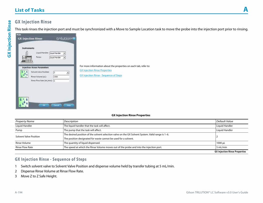
List of Tasks A
A-194 Gilson TRILUTION® LC Software v3.0 User’s Guide
GX
Inje
ctio
n Ri
nse GX Injection Rinse
This task rinses the injection port and must be synchronized with a Move to Sample Location task to move the probe into the injection port prior to rinsing.
GX Injection Rinse - Sequence of Steps1 Switch solvent valve to Solvent Valve Position and dispense volume held by transfer tubing at 5 mL/min.2 Dispense Rinse Volume at Rinse Flow Rate.3 Move Z to Z Safe Height.
For more information about the properties on each tab, refer to:
GX Injection Rinse Properties
GX Injection Rinse - Sequence of Steps
GX Injection Rinse Properties
Property Name Description Default Value
Liquid Handler The liquid handler that the task will affect. Liquid Handler
Pump The pump that the task will affect. Liquid Handler
Solvent Valve PositionThe desired position of the solvent selection valve on the GX Solvent System. Valid range is 1–6.
The position designated for waste cannot be used for a solvent.2
Rinse Volume The quantity of liquid dispensed. 1000 μL
Rinse Flow Rate The speed at which the Rinse Volume moves out of the probe and into the injection port. 5 mL/min
GX Injection Rinse Properties

Gilson TRILUTION® LC Software v3.0 User’s Guide A-195
List of Tasks AG
X Inside Rinse
GX Inside RinseThis task moves to the rinse station and then rinses the inside of the probe.
For more information about the properties on each tab, refer to:
GX Inside Rinse Properties
GX Inside Rinse - Sequence of Steps
GX Inside Rinse Properties For information about rinse positions, refer to Appendix B, Rinse Locations.
Property Name Description Default Value
Liquid Handler The liquid handler that the task will affect. Liquid Handler
Pump The pump that the task will affect. Liquid Handler
Solvent Valve PositionThe desired position of the solvent selection valve on the GX Solvent System. Valid range is 1–6.
The position designated for waste cannot be used for a solvent.2
Inside Rinse Zone The zone to which the Rinse Volume is delivered. Inside Rinse
Inside Rinse Well Enter the well number in the Inside Rinse Zone. 1
Rinse Volume The quantity of liquid used to rinse the inside of the probe. 1000 μL
Rinse Flow Rate The speed at which the Rinse Volume moves out of the probe and into the outside rinse position in the rinse station. 5 mL/min
GX Inside Rinse Properties (Page 1 of 2)

List of Tasks A
A-196 Gilson TRILUTION® LC Software v3.0 User’s Guide
GX
Insi
de R
inse
GX Inside Rinse - Sequence of Steps1 Move Z to Z Safe Height.2 Move to Inside Rinse Well in Inside Rinse Zone.3 Lower probe into well to Inside Rinse Z Option and Inside Rinse Z Offset.4 Switch solvent valve to Solvent Valve Position and dispense volume held by transfer tubing at Rinse Flow Rate.5 Dispense Rinse Volume at Rinse Flow Rate.6 Move Z to Z Safe Height.
Inside Rinse Z Option
One of six defined reference points used when performing the inside rinse:Auto Calculate: Places probe into well and at the liquid level using initial volume from the sample list and well dimensions from the bed layout; accepts a positive (+) or negative (-) value for the Inside Rinse Z Offset.Absolute Value: Moves the probe to the Z-value entered; if 0 is entered for the Inside Rinse Z Offset, the probe will move to the bed bottom (no safety factor incorporated).Tube Bottom: Moves the probe to the well bottom as defined by the bed layout; accepts only positive Inside Rinse Z Offset values to move up from the bottom.Top: Moves probe to the top of their Z-travel range; accepts only a negative (-) value for the Inside Rinse Z Offset.Tube Top: Moves the probe to the top of the well as defined by the bed layout; accepts a positive (+) or negative (-) value for the Inside Rinse Z Offset.Z Adjust: Moves the probe from the current position up (positive value) or down (negative value).
Tube Top
Inside Rinse Z Offset The distance up (when a positive number is entered) or down (when a negative number is entered) from a reference point defined by the Inside Rinse Z Option for rinsing the probe at the inside rinse position in the rinse station. -7 mm
GX Inside Rinse Properties (Continued)For information about rinse positions, refer to Appendix B, Rinse Locations.
Property Name Description Default Value
GX Inside Rinse Properties (Page 2 of 2)

Gilson TRILUTION® LC Software v3.0 User’s Guide A-197
List of Tasks AG
X Mix w
ith Air
GX Mix with AirThis task aspirates air and then dispenses it into a well a specified number of times.
For more information about the properties on each tab, refer to:
GX Mix with Air Properties - Main
GX Mix with Air Properties - Rinsing
GX Mix with Air - Sequence of Steps
GX Mix with Air Properties - Main
Property Name Brief Description Default Value
Liquid Handler The liquid handler that the task will affect. Liquid Handler
Pump The pump that the task will affect. Liquid Handler
Solvent Valve PositionThe desired position of the solvent selection valve on the GX Solvent System. Valid range is 1–6.
The position designated for waste cannot be used for a solvent.2
Mixing Zone The zone in which the Mixing Volume is mixed. Sample Zone
Mixing Well Enter the well number in the Mixing Zone. 0
GX Mix with Air Properties - Main (Page 1 of 2)

List of Tasks A
A-198 Gilson TRILUTION® LC Software v3.0 User’s Guide
GX
Mix
wit
h A
ir
Number of Wells to Mix The number of Mixing Wells to mix. 1
Number of Cycles Type the number of times the task should repeat the commands related to mixing. 2
Mixing Volume The quantity of air used as part of a mixing process. 0
Air Gap Volume The quantity of an air gap. 50 μL
Aspirate Flow Rate The speed at which a volume of air moves into the probe. 1 mL/min
Dispense Flow Rate The speed at which a volume of air moves out of the probe. 5 mL/min
Dispense Z Option
One of six defined reference points used when delivering air to the bed:Auto Calculate: Places probe into well and at the liquid level using initial volume from the sample list and well dimensions from the bed layout; accepts a positive (+) or negative (-) value for the Dispense Z Offset.Absolute Value: Moves the probe to the Z-value entered; if 0 is entered for the Dispense Z Offset, the probe will move to the bed bottom (no safety factor incorporated).Tube Bottom: Moves the probe to the well bottom as defined by the bed layout; accepts only positive Dispense Z Offset values to move up from the bottom.Top: Moves probe to the top of their Z-travel range; accepts only a negative (-) value for the Dispense Z Offset.Tube Top: Moves the probe to the top of the well as defined by the bed layout; accepts a positive (+) or negative (-) value for the Dispense Z Offset.Z Adjust: Moves the probe from the current position up (positive value) or down (negative value).
Tube Bottom
Dispense Z Offset The distance up (when a positive number is entered) or down (when a negative number is entered) from a reference point defined by the Dispense Z Option for delivering air to the bed. 2 mm
Dispense LLFWhen selected, the probe will follow the liquid up as it is delivered to the Mixing Zone. The Dispense Z Option must be set to AUTO CALCULATE and initial volumes must be set in the sample list to use this option.
When cleared, the probe will not follow the liquid up as it is delivered to the Mixing Zone.Cleared
GX Mix with Air Properties - Rinsing For information about rinse positions, refer to Appendix B, Rinse Locations.
Property Name Brief Description Default Value
Inside Rinse Zone The zone to which the Inside Rinse Volume is delivered. Inside Rinse
Inside Rinse Well Enter the well number in the Inside Rinse Zone. 1
Inside Rinse Volume The quantity of liquid used to rinse the inside of the probe. 1000 μL
Inside Rinse Flow Rate The speed at which the Inside Rinse Volume moves out of the probe and into the inside rinse position in the rinse station. 5 mL/min
Inside Rinse Z Option
One of six defined reference points used when performing the inside rinse:Auto Calculate: Places probe into well and at the liquid level using initial volume from the sample list and well dimensions from the bed layout; accepts a positive (+) or negative (-) value for the Inside Rinse Z Offset.Absolute Value: Moves the probe to the Z-value entered; if 0 is entered, probe will move to the bed bottom (no safety factor incorporated).Tube Bottom: Moves the probe to the well bottom as defined by the bed layout; accepts only positive Inside Rinse Z Offset values to move up from the bottom.Top: Moves probe to the top of their Z-travel range; accepts only a negative (-) value for the Inside Rinse Z Offset.Tube Top: Moves the probe to the top of the well as defined by the bed layout; accepts a positive (+) or negative (-) value for the Inside Rinse Z Offset.Z Adjust: Moves the probe from the current position up (positive value) or down (negative value).
Tube Top
Inside Rinse Z Offset The distance up (when a positive number is entered) or down (when a negative number is entered) from a reference point defined by the Inside Rinse Z Option for rinsing the probe at the inside rinse position in the rinse station. -7 mm
GX Mix with Air Properties - Rinsing (Page 1 of 2)
GX Mix with Air Properties - Main (Continued)
Property Name Brief Description Default Value
GX Mix with Air Properties - Main (Page 2 of 2)

Gilson TRILUTION® LC Software v3.0 User’s Guide A-199
List of Tasks AG
X Mix w
ith Air
GX Mix with Air - Sequence of StepsThe following is an overview for the sequence of steps.
1 Mix2 Inside Rinse3 Outside Rinse
Outside Rinse Zone The zone to which the Outside Rinse Volume is delivered. Outside Rinse
Number of Rinse Stations Select the number of rinse stations to be used when performing the outside rinse. Valid range is 1–5. 1
Rinse Well 1 Solvent Valve PositionThe desired position of the solvent selection valve on the GX Solvent System during the outside rinse at rinse station 1. Valid range is 1–6.
The position designated for waste cannot be used for a solvent.2
Rinse Well 2 Solvent Valve PositionThe desired position of the solvent selection valve on the GX Solvent System during the outside rinse at rinse station 2. Valid range is 1–6.
The position designated for waste cannot be used for a solvent.2
Rinse Well 3 Solvent Valve PositionThe desired position of the solvent selection valve on the GX Solvent System during the outside rinse at rinse station 3. Valid range is 1–6.
The position designated for waste cannot be used for a solvent.2
Rinse Well 4 Solvent Valve PositionThe desired position of the solvent selection valve on the GX Solvent System during the outside rinse at rinse station 4. Valid range is 1–6.
The position designated for waste cannot be used for a solvent.2
Rinse Well 5 Solvent Valve PositionThe desired position of the solvent selection valve on the GX Solvent System during the outside rinse at rinse station 5. Valid range is 1–6.
The position designated for waste cannot be used for a solvent.2
Outside Rinse Volume The quantity of liquid used to rinse the outside of the probe. 2000 μL
Outside Rinse Flow Rate The speed at which the Outside Rinse Volume moves out of the probe and into the outside rinse position in the rinse station. 5 mL/min
Outside Rinse Z Option
One of six defined reference points used when performing the outside rinse:Auto Calculate: Places probe into well and at the liquid level using initial volume from the sample list and well dimensions from the bed layout; accepts a positive (+) or negative (-) value for the Outside Rinse Z Offset.Absolute Value: Moves the probe to the Z-value entered; if 0 is entered for the Outside Rinse Z Offset, the probe will move to the bed bottom (no safety factor incorporated).Tube Bottom: Moves the probe to the well bottom as defined by the bed layout; accepts only positive Outside Rinse Z Offset values to move up from the bottom.Top: Moves probe to the top of their Z-travel range; accepts only a negative (-) value for the Outside Rinse Z Offset.Tube Top: Moves the probe to the top of the well as defined by the bed layout; accepts a positive (+) or negative (-) value for the Outside Rinse Z Offset.Z Adjust: Moves the probe from the current position up (positive value) or down (negative value).
Tube Bottom
Outside Rinse Z Offset The distance up (when a positive number is entered) or down (when a negative number is entered) from a reference point defined by the Outside Rinse Z Option for rinsing the probe at the outside rinse position in the rinse station. 2 mm
Rinse Pump The rinse pump that will be used for the flowing outside rinse. Select 1 if the rinse pump is wired to Output 1 and 24V Output 1 or select 2 if the rinse pump is wired to Output 2 and 24V Output 2. 1
Rinse Pump Speed Select HIGH, LOW, or OFF. OFF
GX Mix with Air Properties - Rinsing (Continued)For information about rinse positions, refer to Appendix B, Rinse Locations.
Property Name Brief Description Default Value
GX Mix with Air Properties - Rinsing (Page 2 of 2)

List of Tasks A
A-200 Gilson TRILUTION® LC Software v3.0 User’s Guide
GX
Mix
wit
h A
ir Mix1 Move Z to Z Safe Height.2 Move to Mixing Well in Mixing Zone.3 Move Z to Z Safe Height.4 Switch solvent valve to waste and aspirate Air Gap Volume (first cycle only) and Mixing Volume at Aspirate Flow Rate.5 Lower probe to Dispense Z Option and Dispense Z Offset.6 Switch solvent valve to Solvent Valve Position and dispense Mixing Volume at Dispense Flow Rate.7 Repeat steps 3–6 for Number of Cycles.8 Move Z to Z Safe Height.
Inside Rinse1 Move Z to Z Safe Height.2 Move to Inside Rinse Well in Inside Rinse Zone.3 Lower probe into well to Inside Rinse Z Option and Inside Rinse Z Offset.4 Switch solvent valve to Solvent Valve Position and dispense volume held by transfer tubing at Inside Rinse Flow Rate.5 Dispense Inside Rinse Volume at Inside Rinse Flow Rate.6 Move Z to Z Safe Height.
Outside Rinse1 Move Z to Z Safe Height.2 Move to rinse station/well 1 in Outside Rinse Zone.3 Lower probe into well to Outside Rinse Z Option and Outside Rinse Z Offset.4 Switch Rinse Pump on at Rinse Pump Speed.5 Switch solvent valve to Rinse Well 1 Solvent Valve Position and dispense Outside Rinse Volume at Outside Rinse Flow Rate. If the current solvent valve position
is not the same as the previous solvent valve position, dispense Outside Rinse Volume + 2000 uL + Transfer Tubing volume.6 Switch Rinse Pump off.7 Move Z to Z Safe Height.8 Repeat steps 3–7 for the Number of Rinse Stations, incrementing the rinse station/well for each rinse station.9 Repeat Number of wells to mix.

Gilson TRILUTION® LC Software v3.0 User’s Guide A-201
List of Tasks AG
X Mix w
ith Liquid
GX Mix with LiquidThis task aspirates liquid and then dispenses it into a well a specified number of times.
For more information about the properties on each tab, refer to:
GX Mix with Liquid Properties - Main
GX Mix with Liquid Properties - Rinsing
GX Mix with Liquid - Sequence of Steps
GX Mix with Liquid Properties - Main
Property Name Brief Description Default Value
Liquid Handler The liquid handler that the task will affect. Liquid Handler
Pump The pump that the task will affect. Liquid Handler
Solvent Valve PositionThe desired position of the solvent selection valve on the GX Solvent System. Valid range is 1–6.
The position designated for waste cannot be used for a solvent.2
Mixing Zone The zone in which the Mixing Volume is mixed. Sample Zone
Mixing Well Enter the well number in the Mixing Zone. 0
GX Mix with Liquid Properties - Main (Page 1 of 2)

List of Tasks A
A-202 Gilson TRILUTION® LC Software v3.0 User’s Guide
GX
Mix
wit
h Li
quid
Number of Wells to Mix The number of Mixing Wells to mix. 1
Number of Cycles Type the number of times the task should repeat the commands related to mixing. 2
Mixing Volume The quantity of liquid used as part of a mixing process. 0
Air Gap Volume The quantity of an air gap. 50 μL
Aspirate Flow Rate The speed at which the Mixing Volume moves into the probe. 1 mL/min
Dispense Flow Rate The speed at which the Mixing Volume moves out of the probe. 5 mL/min
Air Gap Flow Rate The speed at which the Air Gap Volume moves into the probe. 1 mL/min
Aspirate Z Option
One of six defined reference points used when drawing liquids from the bed:Auto Calculate: Places probe into well and at the liquid level using initial volume from the sample list and well dimensions from the bed layout; accepts a positive (+) or negative (-) value for the Aspirate Z Offset.Absolute Value: Moves the probe to the Z-value entered; if 0 is entered for the Aspirate Z Offset, the probe will move to the bed bottom (no safety factor incorporated).Tube Bottom: Moves the probe to the well bottom as defined by the bed layout; accepts only positive Aspirate Z Offset values to move up from the bottom.Top: Moves probe to the top of their Z-travel range; accepts only a negative (-) value for the Aspirate Z Offset.Tube Top: Moves the probe to the top of the well as defined by the bed layout; accepts a positive (+) or negative (-) value for the Aspirate Z Offset.Z Adjust: Moves the probe from the current position up (positive value) or down (negative value).
Tube Bottom
Aspirate Z Offset The distance up (when a positive number is entered) or down (when a negative number is entered) from a reference point defined by the Aspirate Z Option for drawing liquids from the bed. 2 mm
Aspirate LLFWhen selected, the probe will follow the liquid down as it is aspirated from the Mixing Zone. The Aspirate Z Option must be set to AUTO CALCULATE and initial volumes must be set in the sample list to use this option.
When cleared, the probe will not follow the liquid down as it is aspirated from the Mixing Zone.Cleared
Dispense Z Option
One of six defined reference points used when delivering liquids to the bed:Auto Calculate: Places probe into well and at the liquid level using initial volume from the sample list and well dimensions from the bed layout; accepts a positive (+) or negative (-) value for the Dispense Z Offset.Absolute Value: Moves the probe to the Z-value entered; if 0 is entered for the Dispense Z Offset, the probe will move to the bed bottom (no safety factor incorporated).Tube Bottom: Moves the probe to the well bottom as defined by the bed layout; accepts only positive Dispense Z Offset values to move up from the bottom.Top: Moves probe to the top of their Z-travel range; accepts only a negative (-) value for the Dispense Z Offset.Tube Top: Moves the probe to the top of the well as defined by the bed layout; accepts a positive (+) or negative (-) value for the Dispense Z Offset.Z Adjust: Moves the probe from the current position up (positive value) or down (negative value).
Tube Bottom
Dispense Z Offset The distance up (when a positive number is entered) or down (when a negative number is entered) from a reference point defined by the Dispense Z Option for delivering liquids to the bed. 2
Dispense LLFWhen selected, the probe will follow the liquid up as it is delivered to the Mixing Zone. The Dispense Z Option must be set to AUTO CALCULATE and initial volumes must be set in the sample list to use this option.
When cleared, the probe will not follow the liquid up as it is delivered to the Mixing Zone.Cleared
GX Mix with Liquid Properties - Main (Continued)
Property Name Brief Description Default Value
GX Mix with Liquid Properties - Main (Page 2 of 2)
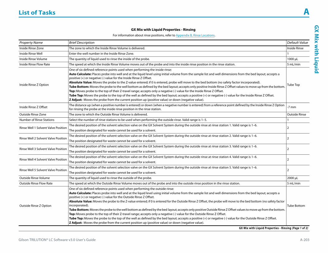
Gilson TRILUTION® LC Software v3.0 User’s Guide A-203
List of Tasks AG
X Mix w
ith Liquid
GX Mix with Liquid Properties - Rinsing For information about rinse positions, refer to Appendix B, Rinse Locations.
Property Name Brief Description Default Value
Inside Rinse Zone The zone to which the Inside Rinse Volume is delivered. Inside Rinse
Inside Rinse Well Enter the well number in the Inside Rinse Zone. 1
Inside Rinse Volume The quantity of liquid used to rinse the inside of the probe. 1000 μL
Inside Rinse Flow Rate The speed at which the Inside Rinse Volume moves out of the probe and into the inside rinse position in the rinse station. 5 mL/min
Inside Rinse Z Option
One of six defined reference points used when performing the inside rinse:Auto Calculate: Places probe into well and at the liquid level using initial volume from the sample list and well dimensions from the bed layout; accepts a positive (+) or negative (-) value for the Inside Rinse Z Offset.Absolute Value: Moves the probe to the Z-value entered; if 0 is entered, probe will move to the bed bottom (no safety factor incorporated).Tube Bottom: Moves the probe to the well bottom as defined by the bed layout; accepts only positive Inside Rinse Z Offset values to move up from the bottom.Top: Moves probe to the top of their Z-travel range; accepts only a negative (-) value for the Inside Rinse Z Offset.Tube Top: Moves the probe to the top of the well as defined by the bed layout; accepts a positive (+) or negative (-) value for the Inside Rinse Z Offset.Z Adjust: Moves the probe from the current position up (positive value) or down (negative value).
Tube Top
Inside Rinse Z Offset The distance up (when a positive number is entered) or down (when a negative number is entered) from a reference point defined by the Inside Rinse Z Option for rinsing the probe at the inside rinse position in the rinse station. -7 mm
Outside Rinse Zone The zone to which the Outside Rinse Volume is delivered. Outside Rinse
Number of Rinse Stations Select the number of rinse stations to be used when performing the outside rinse. Valid range is 1–5. 1
Rinse Well 1 Solvent Valve PositionThe desired position of the solvent selection valve on the GX Solvent System during the outside rinse at rinse station 1. Valid range is 1–6.
The position designated for waste cannot be used for a solvent.2
Rinse Well 2 Solvent Valve PositionThe desired position of the solvent selection valve on the GX Solvent System during the outside rinse at rinse station 2. Valid range is 1–6.
The position designated for waste cannot be used for a solvent.2
Rinse Well 3 Solvent Valve PositionThe desired position of the solvent selection valve on the GX Solvent System during the outside rinse at rinse station 3. Valid range is 1–6.
The position designated for waste cannot be used for a solvent.2
Rinse Well 4 Solvent Valve PositionThe desired position of the solvent selection valve on the GX Solvent System during the outside rinse at rinse station 4. Valid range is 1–6.
The position designated for waste cannot be used for a solvent.2
Rinse Well 5 Solvent Valve PositionThe desired position of the solvent selection valve on the GX Solvent System during the outside rinse at rinse station 5. Valid range is 1–6.
The position designated for waste cannot be used for a solvent.2
Outside Rinse Volume The quantity of liquid used to rinse the outside of the probe. 2000 μL
Outside Rinse Flow Rate The speed at which the Outside Rinse Volume moves out of the probe and into the outside rinse position in the rinse station. 5 mL/min
Outside Rinse Z Option
One of six defined reference points used when performing the outside rinse:Auto Calculate: Places probe into well and at the liquid level using initial volume from the sample list and well dimensions from the bed layout; accepts a positive (+) or negative (-) value for the Outside Rinse Z Offset.Absolute Value: Moves the probe to the Z-value entered; if 0 is entered for the Outside Rinse Z Offset, the probe will move to the bed bottom (no safety factor incorporated).Tube Bottom: Moves the probe to the well bottom as defined by the bed layout; accepts only positive Outside Rinse Z Offset values to move up from the bottom.Top: Moves probe to the top of their Z-travel range; accepts only a negative (-) value for the Outside Rinse Z Offset.Tube Top: Moves the probe to the top of the well as defined by the bed layout; accepts a positive (+) or negative (-) value for the Outside Rinse Z Offset.Z Adjust: Moves the probe from the current position up (positive value) or down (negative value).
Tube Bottom
GX Mix with Liquid Properties - Rinsing (Page 1 of 2)

List of Tasks A
A-204 Gilson TRILUTION® LC Software v3.0 User’s Guide
GX
Mix
wit
h Li
quid
GX Mix with Liquid - Sequence of StepsThe following is an overview for the sequence of steps.
1 Mix2 Inside Rinse3 Outside Rinse
Mix1 Move Z to Z Safe Height.2 Switch solvent valve to waste and aspirate Air Gap Volume at Air Gap Flow Rate.3 Move to Mixing Well in Mixing Zone.4 Lower probe to Aspirate Z Option and Aspirate Z Offset.5 Switch solvent valve to waste and aspirate Mixing Volume at Aspirate Flow Rate.6 Lower probe to Dispense Z Option and Dispense Z Offset.7 Switch solvent valve to Solvent Valve Position and dispense Mixing Volume at Dispense Flow Rate.8 Repeat steps 4–7 for Number of Cycles.9 Move Z to Z Safe Height.
Inside Rinse1 Move Z to Z Safe Height.2 Move to Inside Rinse Well in Inside Rinse Zone.3 Lower probe into well to Inside Rinse Z Option and Inside Rinse Z Offset.4 Switch solvent valve to Solvent Valve Position and dispense volume held by transfer tubing at Inside Rinse Flow Rate.5 Dispense Inside Rinse Volume at Inside Rinse Flow Rate.6 Move Z to Z Safe Height.
Outside Rinse Z Offset The distance up (when a positive number is entered) or down (when a negative number is entered) from a reference point defined by the Outside Rinse Z Option for rinsing the probe at the outside rinse position in the rinse station. 2 mm
Rinse Pump The rinse pump that will be used for the flowing outside rinse. Select 1 if the rinse pump is wired to Output 1 and 24V Output 1 or select 2 if the rinse pump is wired to Output 2 and 24V Output 2. 1
Rinse Pump Speed Select HIGH, LOW, or OFF. OFF
GX Mix with Liquid Properties - Rinsing (Continued)For information about rinse positions, refer to Appendix B, Rinse Locations.
Property Name Brief Description Default Value
GX Mix with Liquid Properties - Rinsing (Page 2 of 2)

Gilson TRILUTION® LC Software v3.0 User’s Guide A-205
List of Tasks AG
X Mix w
ith Liquid
Outside Rinse1 Move Z to Z Safe Height.2 Move to rinse station/well 1 in Outside Rinse Zone.3 Lower probe into well to Outside Rinse Z Option and Outside Rinse Z Offset.4 Switch Rinse Pump on at Rinse Pump Speed.5 Switch solvent valve to Rinse Well 1 Solvent Valve Position and dispense Outside Rinse Volume at Outside Rinse Flow Rate. If the current solvent valve position
is not the same as the previous solvent valve position, dispense Outside Rinse Volume + 2000 uL + Transfer Tubing volume.6 Switch Rinse Pump off.7 Move Z to Z Safe Height.8 Repeat steps 2–7 for the Number of Rinse Stations, incrementing the rinse station/well for each rinse station.

List of Tasks A
A-206 Gilson TRILUTION® LC Software v3.0 User’s Guide
GX
Out
side
Rin
se GX Outside RinseThis task moves to the rinse station and then rinses the outside of the probe.
For more information about the properties on each tab, refer to:
GX Outside Rinse Properties
GX Outside Rinse - Sequence of Steps
GX Outside Rinse Properties For information about rinse positions, refer to Appendix B, Rinse Locations.
Property Name Description Default Value
Liquid Handler The liquid handler that the task will affect. Liquid Handler
Pump The pump that the task will affect. Liquid Handler
Purge Solvent Valve PositionThe desired position of the solvent selection valve on the GX Solvent System. Valid range is 1–6.
The position designated for waste cannot be used for a solvent.2
Outside Rinse Zone The zone to which the Outside Rinse Volume is delivered. Outside Rinse
Number of Rinse Stations Select the number of rinse stations to be used when performing the outside rinse. Valid range is 1–5. 1
Rinse Well 1 Solvent Valve PositionThe desired position of the solvent selection valve on the GX Solvent System during the outside rinse at rinse station 1. Valid range is 1–6.
The position designated for waste cannot be used for a solvent.2
GX Outside Rinse Properties (Page 1 of 2)
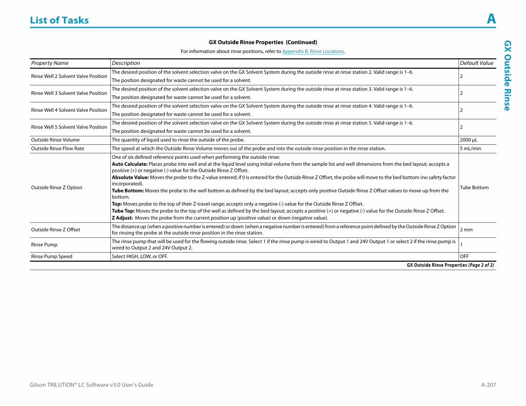
Gilson TRILUTION® LC Software v3.0 User’s Guide A-207
List of Tasks AG
X Outside Rinse
Rinse Well 2 Solvent Valve PositionThe desired position of the solvent selection valve on the GX Solvent System during the outside rinse at rinse station 2. Valid range is 1–6.
The position designated for waste cannot be used for a solvent.2
Rinse Well 3 Solvent Valve PositionThe desired position of the solvent selection valve on the GX Solvent System during the outside rinse at rinse station 3. Valid range is 1–6.
The position designated for waste cannot be used for a solvent.2
Rinse Well 4 Solvent Valve PositionThe desired position of the solvent selection valve on the GX Solvent System during the outside rinse at rinse station 4. Valid range is 1–6.
The position designated for waste cannot be used for a solvent.2
Rinse Well 5 Solvent Valve PositionThe desired position of the solvent selection valve on the GX Solvent System during the outside rinse at rinse station 5. Valid range is 1–6.
The position designated for waste cannot be used for a solvent.2
Outside Rinse Volume The quantity of liquid used to rinse the outside of the probe. 2000 μL
Outside Rinse Flow Rate The speed at which the Outside Rinse Volume moves out of the probe and into the outside rinse position in the rinse station. 5 mL/min
Outside Rinse Z Option
One of six defined reference points used when performing the outside rinse:Auto Calculate: Places probe into well and at the liquid level using initial volume from the sample list and well dimensions from the bed layout; accepts a positive (+) or negative (-) value for the Outside Rinse Z Offset.Absolute Value: Moves the probe to the Z-value entered; if 0 is entered for the Outside Rinse Z Offset, the probe will move to the bed bottom (no safety factor incorporated).Tube Bottom: Moves the probe to the well bottom as defined by the bed layout; accepts only positive Outside Rinse Z Offset values to move up from the bottom.Top: Moves probe to the top of their Z-travel range; accepts only a negative (-) value for the Outside Rinse Z Offset.Tube Top: Moves the probe to the top of the well as defined by the bed layout; accepts a positive (+) or negative (-) value for the Outside Rinse Z Offset.Z Adjust: Moves the probe from the current position up (positive value) or down (negative value).
Tube Bottom
Outside Rinse Z Offset The distance up (when a positive number is entered) or down (when a negative number is entered) from a reference point defined by the Outside Rinse Z Option for rinsing the probe at the outside rinse position in the rinse station. 2 mm
Rinse Pump The rinse pump that will be used for the flowing outside rinse. Select 1 if the rinse pump is wired to Output 1 and 24V Output 1 or select 2 if the rinse pump is wired to Output 2 and 24V Output 2. 1
Rinse Pump Speed Select HIGH, LOW, or OFF. OFF
GX Outside Rinse Properties (Continued)For information about rinse positions, refer to Appendix B, Rinse Locations.
Property Name Description Default Value
GX Outside Rinse Properties (Page 2 of 2)

List of Tasks A
A-208 Gilson TRILUTION® LC Software v3.0 User’s Guide
GX
Out
side
Rin
se GX Outside Rinse - Sequence of Steps1 Move Z to Z Safe Height.2 Move to rinse station/well 1 in Outside Rinse Zone.3 Lower probe into well to Outside Rinse Z Option and Outside Rinse Z Offset.4 Switch valve to Purge Solvent Valve Position and dispense volume held by transfer tubing at Outside Rinse Flow Rate.5 Switch Rinse Pump on at Rinse Pump Speed.6 Move to rinse station/well 1 in Outside Rinse Zone.7 Lower probe into well to Outside Rinse Z Option and Outside Rinse Z Offset.8 Switch solvent valve to Rinse Well 1 Solvent Valve Position and dispense Outside Rinse Volume at Outside Rinse Flow Rate. If the current solvent valve position
is not the same as the previous solvent valve position, dispense Outside Rinse Volume + 2000 uL + Transfer Tubing volume.9 Switch Rinse Pump off.10 Move Z to Z Safe Height.11 Repeat steps 2–7 for the Number of Rinse Stations, incrementing the rinse station/well for each rinse station.

Gilson TRILUTION® LC Software v3.0 User’s Guide A-209
List of Tasks AG
X Prime
GX PrimeThis task primes the transfer tubing. It dispenses the transfer tubing capacity from the reservoir to the specified wells in the specified zone for the number of cycles.
For more information about the properties on each tab, refer to:
GX Prime Properties
GX Prime - Sequence of Steps
GX Prime Properties
Property Name Description Default Value
Liquid Handler The liquid handler that the task will affect. Liquid Handler
Pump The pump that the task will affect. Liquid Handler
Solvent Valve Position The desired position of the solvent selection valve on the GX Solvent System. Valid range is 1–6. 2
Number of Cycles Enter the number of times to repeat dispensing. 3
Flow Rate The speed at which the liquid moves out of the probe. 5 mL/min
Zone The zone to which the volume is dispensed. Inside Rinse
Well Enter the well number in the Zone. 1
GX Prime Properties (Page 1 of 2)
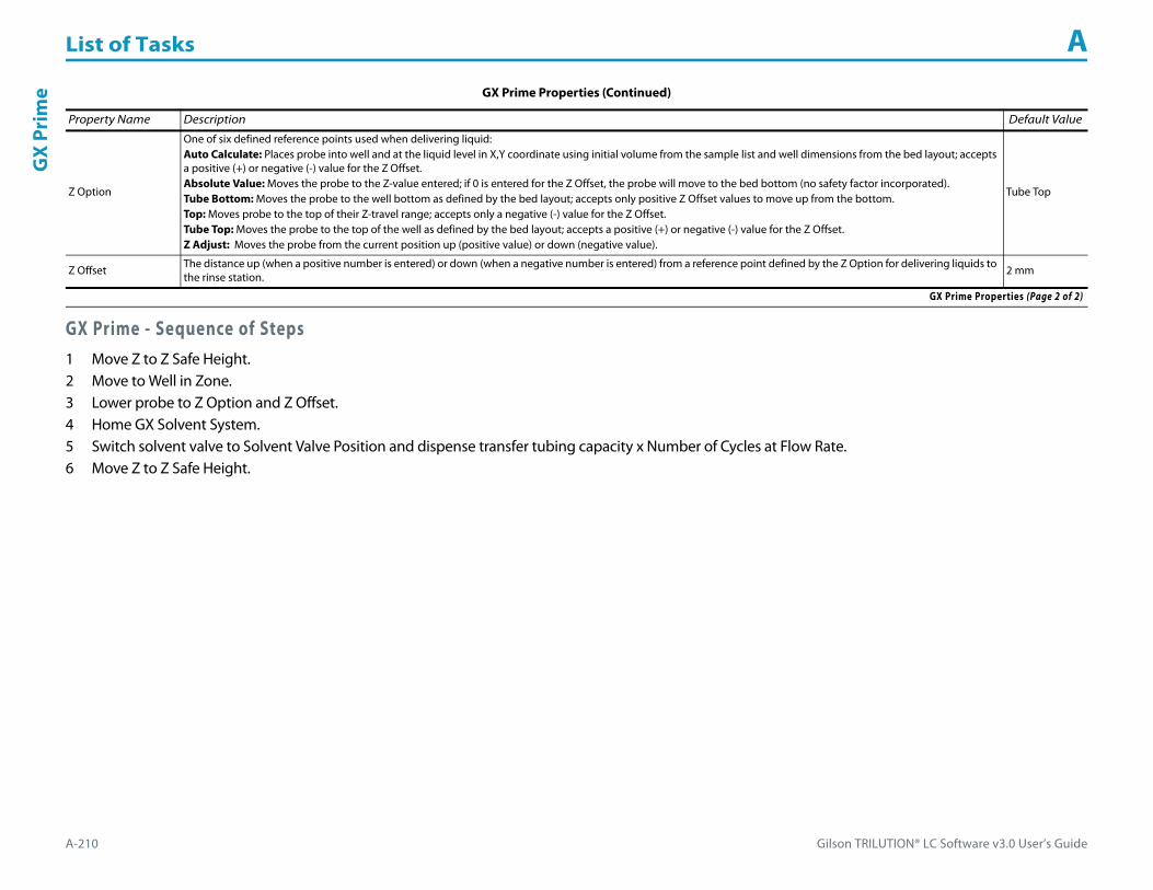
List of Tasks A
A-210 Gilson TRILUTION® LC Software v3.0 User’s Guide
GX
Prim
e
GX Prime - Sequence of Steps1 Move Z to Z Safe Height.2 Move to Well in Zone.3 Lower probe to Z Option and Z Offset.4 Home GX Solvent System.5 Switch solvent valve to Solvent Valve Position and dispense transfer tubing capacity x Number of Cycles at Flow Rate.6 Move Z to Z Safe Height.
Z Option
One of six defined reference points used when delivering liquid:Auto Calculate: Places probe into well and at the liquid level in X,Y coordinate using initial volume from the sample list and well dimensions from the bed layout; accepts a positive (+) or negative (-) value for the Z Offset.Absolute Value: Moves the probe to the Z-value entered; if 0 is entered for the Z Offset, the probe will move to the bed bottom (no safety factor incorporated).Tube Bottom: Moves the probe to the well bottom as defined by the bed layout; accepts only positive Z Offset values to move up from the bottom.Top: Moves probe to the top of their Z-travel range; accepts only a negative (-) value for the Z Offset.Tube Top: Moves the probe to the top of the well as defined by the bed layout; accepts a positive (+) or negative (-) value for the Z Offset.Z Adjust: Moves the probe from the current position up (positive value) or down (negative value).
Tube Top
Z Offset The distance up (when a positive number is entered) or down (when a negative number is entered) from a reference point defined by the Z Option for delivering liquids to the rinse station.
2 mm
GX Prime Properties (Continued)
Property Name Description Default Value
GX Prime Properties (Page 2 of 2)

Gilson TRILUTION® LC Software v3.0 User’s Guide A-211
List of Tasks AG
X Transfer
GX TransferThis task aspirates the specified volume of liquid (Source Volume) from the probe and then dispenses the volume to the wells of the result zone.
For more information about the properties on each tab, refer to:
GX Transfer Properties - Main
GX Transfer Properties - Rinsing
GX Transfer - Sequence of Steps
GX Transfer Properties - Main
Property Name Description Default Value
Liquid Handler The liquid handler that the task will affect. Liquid Handler
Pump The pump that the task will affect. Liquid Handler
Solvent Valve PositionThe desired position of the solvent selection valve on the GX Solvent System. Valid range is 1–6.
The position designated for waste cannot be used for a solvent.2
Source Zone The zone from which the Source Volume and Source Extra Volume are drawn. Sample Zone
GX Transfer Properties - Main (Page 1 of 2)

List of Tasks A
A-212 Gilson TRILUTION® LC Software v3.0 User’s Guide
GX
Tran
sfer
Source Well Enter the well number in the Source Zone. 0
Result Zone The zone to which the Source Volume is delivered. Sample Zone
Result Well Enter the well number in the Result Zone. 0
Number of Wells to Transfer The number of Source Wells to transfer to Result Wells. 1
Air Gap Volume The quantity of the air gap aspirated before the Source Volume. 50 μL
Source Volume The quantity of sample 0
Extra Volume An additional volume to the first volume aspirated. It ensures that the actual volume of liquid to be transferred is not contaminated, and acts as an extra buffer between the air gap/reservoir solvent and the Source Volume.
0
Aspirate Flow Rate The speed at which the Source Volume and Extra Volume move into the probe. 1.5 mL/min
Dispense Flow Rate The speed at which the Source Volume moves out of the probe. 3 mL/min
Air Gap Flow Rate The speed at which the Air Gap Volume moves into the probe. 1 mL/min
Aspirate Z Option
One of six defined reference points used when drawing liquids from the bed:Auto Calculate: Places probe into well and at the liquid level in X,Y coordinate using initial volume from the sample list and well dimensions from the bed layout; accepts a positive (+) or negative (-) value for the Aspirate Z Offset.Absolute Value: Moves the probe to the Z-value entered; if 0 is entered, the probe will move to the bed bottom (no safety factor incorporated).Tube Bottom: Moves the probe to the well bottom as defined by the bed layout; accepts only positive Aspirate Z Offset values to move up from the bottom.Top: Moves probe to the top of their Z-travel range; accepts only a negative (-) value for the Aspirate Z Offset.Tube Top: Moves the probe to the top of the well as defined by the bed layout; accepts a positive (+) or negative (-) value for the Aspirate Z Offset.Z Adjust: Moves the probe from the current position up (positive value) or down (negative value).
Tube Bottom
Aspirate Z Offset The distance up (when a positive number is entered) or down (when a negative number is entered) from a reference point defined by the Aspirate Z Option for drawing liquids from the bed. 2 mm
Aspirate LLFWhen selected, the probe will follow the liquid down as it is aspirated from the Source Zone. The Aspirate Z Option must be set to AUTO CALCULATE and initial volumes must be set in the sample list to use this option.
When cleared, the probe will not follow the liquid down as it is aspirated from the Source Zone.Cleared
Dispense Z Option
One of six defined reference points used when delivering liquids to the bed:Auto Calculate: Places probe into well and at the liquid level in X,Y coordinate using initial volume from the sample list and well dimensions from the bed layout; accepts a positive (+) or negative (-) value for the Dispense Z Offset.Absolute Value: Moves the probe to the Z-value entered; if 0 is entered, the probe will move to the bed bottom (no safety factor incorporated).Tube Bottom: Moves the probe to the well bottom as defined by the bed layout; accepts only positive Dispense Z Offset values to move up from the bottom.Top: Moves probe to the top of their Z-travel range; accepts only a negative (-) value for the Dispense Z Offset.Tube Top: Moves the probe to the top of the well as defined by the bed layout; accepts a positive (+) or negative (-) value for the Dispense Z Offset. Z Adjust: Moves the probe from the current position up (positive value) or down (negative value).
Tube Bottom
Dispense Z Offset The distance up (when a positive number is entered) or down (when a negative number is entered) from a reference point defined by the Dispense Z Option for delivering liquids to the bed. 2 mm
Dispense LLFWhen selected, the probe will follow the liquid up as it is delivered to the Result Zone. The Dispense Z Option must be set to AUTO CALCULATE and initial volumes must be set in the sample list to use this option.
When cleared, the probe will not follow the liquid up as it is delivered to the Result Zone.Cleared
GX Transfer Properties - Main (Continued)
Property Name Description Default Value
GX Transfer Properties - Main (Page 2 of 2)

Gilson TRILUTION® LC Software v3.0 User’s Guide A-213
List of Tasks AG
X Transfer
GX Transfer Properties - Rinsing For information about rinse positions, refer to Appendix B, Rinse Locations.
Property Name Description Default Value
Inside Rinse Zone The zone to which the Inside Rinse Volume is delivered. Inside Rinse
Inside Rinse Well Enter the well number in the Inside Rinse Zone. 1
Inside Rinse Volume The quantity of liquid used to rinse the inside of the probe. 1000 μL
Inside Rinse Flow Rate The speed at which the Inside Rinse Volume moves out of the probe and into the inside rinse position in the rinse station. 5 mL/min
Inside Rinse Z Option
One of six defined reference points used when performing the inside rinse:Auto Calculate: Places probe into well and at the liquid level using initial volume from the sample list and well dimensions from the bed layout; accepts a positive (+) or negative (-) value for the Inside Rinse Z Offset.Absolute Value: Moves the probe to the Z-value entered; if 0 is entered, the probe will move to the bed bottom (no safety factor incorporated).Tube Bottom: Moves the probe to the well bottom as defined by the bed layout; accepts only positive Inside Rinse Z Offset values to move up from the bottom.Top: Moves probe to the top of their Z-travel range; accepts only a negative (-) value for the Inside Rinse Z Offset.Tube Top: Moves the probe to the top of the well as defined by the bed layout; accepts a positive (+) or negative (-) value for the Inside Rinse Z Offset.Z Adjust: Moves the probe from the current position up (positive value) or down (negative value).
Tube Top
Inside Rinse Z Offset The distance up (when a positive number is entered) or down (when a negative number is entered) from a reference point defined by the Inside Rinse Z Option for rinsing the probe at the inside rinse position in the rinse station. -7 mm
Outside Rinse Zone The zone to which the Outside Rinse Volume is delivered. Outside Rinse
Number of Rinse Stations Select the number of rinse stations to be used when performing the outside rinse. Valid range is 1–5. 1
Rinse Well 1 Solvent Valve PositionThe desired position of the solvent selection valve on the GX Solvent System during the outside rinse at rinse station 1. Valid range is 1–6.
The position designated for waste cannot be used for a solvent.2
Rinse Well 2 Solvent Valve PositionThe desired position of the solvent selection valve on the GX Solvent System during the outside rinse at rinse station 2. Valid range is 1–6.
The position designated for waste cannot be used for a solvent.2
Rinse Well 3 Solvent Valve PositionThe desired position of the solvent selection valve on the GX Solvent System during the outside rinse at rinse station 3. Valid range is 1–6.
The position designated for waste cannot be used for a solvent.2
Rinse Well 4 Solvent Valve PositionThe desired position of the solvent selection valve on the GX Solvent System during the outside rinse at rinse station 4. Valid range is 1–6.
The position designated for waste cannot be used for a solvent.2
Rinse Well 5 Solvent Valve PositionThe desired position of the solvent selection valve on the GX Solvent System during the outside rinse at rinse station 5. Valid range is 1–6.
The position designated for waste cannot be used for a solvent.2
Outside Rinse Volume The quantity of liquid used to rinse the outside of the probe. 2000 μL
Outside Rinse Flow Rate The speed at which the Outside Rinse Volume moves out of the probe and into the outside rinse position in the rinse station. 5 mL/min
Outside Rinse Z Option
One of six defined reference points used when performing the outside rinse:Auto Calculate: Places probe into well and at the liquid level using initial volume from the sample list and well dimensions from the bed layout; accepts a positive (+) or negative (-) value for the Outside Rinse Z Offset.Absolute Value: Moves the probe to the Z-value entered; if 0 is entered, the probe will move to the bed bottom (no safety factor incorporated).Tube Bottom: Moves the probe to the well bottom as defined by the bed layout; accepts only positive Outside Rinse Z Offset values to move up from the bottom.Top: Moves probe to the top of their Z-travel range; accepts only a negative (-) value for the Outside Rinse Z Offset.Tube Top: Moves the probe to the top of the well as defined by the bed layout; accepts a positive (+) or negative (-) value for the Outside Rinse Z Offset.Z Adjust: Moves the probe from the current position up (positive value) or down (negative value).
Tube Bottom
GX Transfer Properties - Rinsing (Page 1 of 2)

List of Tasks A
A-214 Gilson TRILUTION® LC Software v3.0 User’s Guide
GX
Tran
sfer
GX Transfer - Sequence of StepsThe following is an overview for the sequence of steps.
1 Aspirate2 Dispense3 Inside Rinse4 Outside Rinse
Aspirate1 Move Z to Z Safe Height.2 Switch solvent valve to waste and aspirate Air Gap Volume at Air Gap Flow Rate.3 Move to Source Well in Source Zone.4 Lower probe to Aspirate Z Option and Aspirate Z Offset.5 Aspirate Source Volume + Extra Volume at Aspirate Flow Rate.6 Move Z to Z Safe Height.
Outside Rinse Z Offset The distance up (when a positive number is entered) or down (when a negative number is entered) from a reference point defined by the Outside Rinse Z Option for rinsing the probe at the outside rinse position in the rinse station. 2 mm
Rinse Pump The rinse pump that will be used for the flowing outside rinse. Select 1 if the rinse pump is wired to Output 1 and 24V Output 1 or select 2 if the rinse pump is wired to Output 2 and 24V Output 2. 1
Rinse Pump Speed Select HIGH, LOW, or OFF. OFF
GX Transfer Properties - Rinsing (Continued)For information about rinse positions, refer to Appendix B, Rinse Locations.
Property Name Description Default Value
GX Transfer Properties - Rinsing (Page 2 of 2)
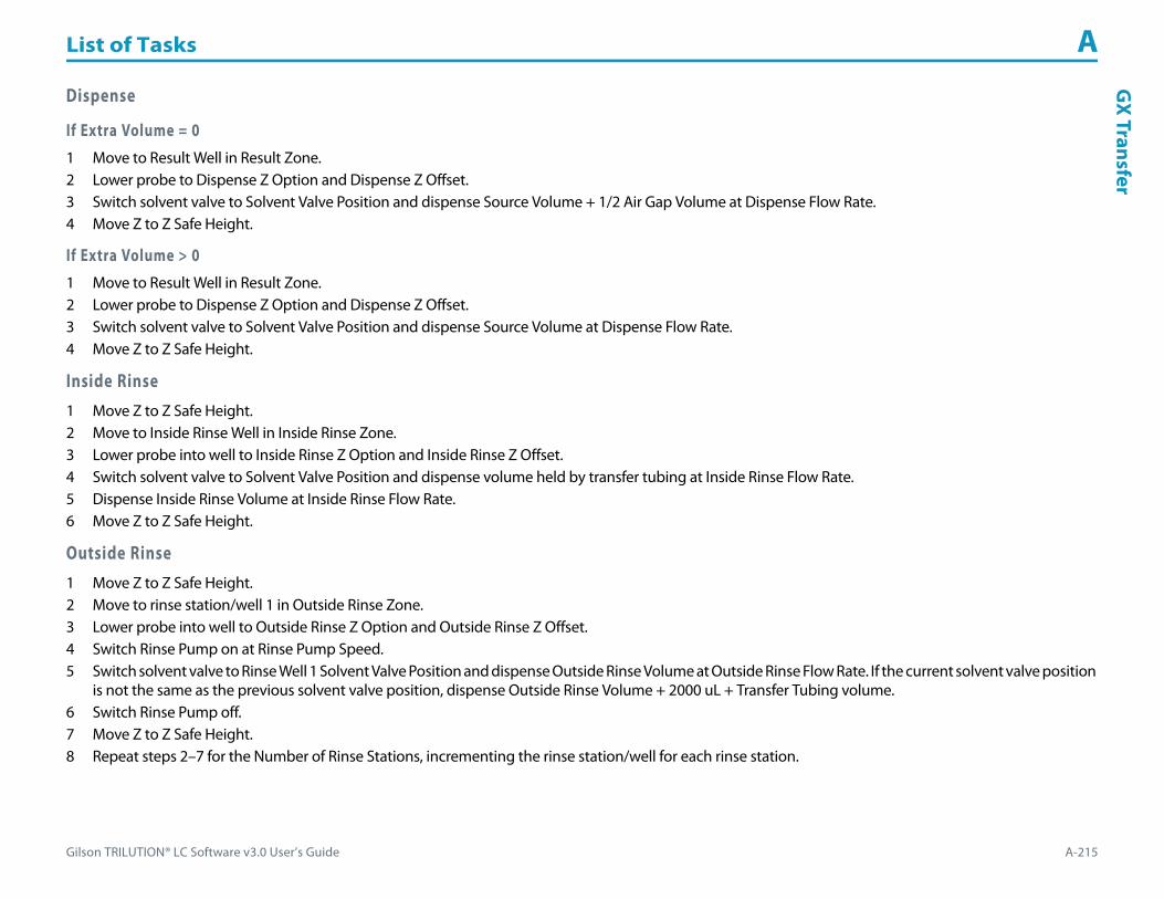
Gilson TRILUTION® LC Software v3.0 User’s Guide A-215
List of Tasks AG
X Transfer
Dispense
If Extra Volume = 01 Move to Result Well in Result Zone.2 Lower probe to Dispense Z Option and Dispense Z Offset.3 Switch solvent valve to Solvent Valve Position and dispense Source Volume + 1/2 Air Gap Volume at Dispense Flow Rate.4 Move Z to Z Safe Height.
If Extra Volume > 01 Move to Result Well in Result Zone.2 Lower probe to Dispense Z Option and Dispense Z Offset.3 Switch solvent valve to Solvent Valve Position and dispense Source Volume at Dispense Flow Rate.4 Move Z to Z Safe Height.
Inside Rinse1 Move Z to Z Safe Height.2 Move to Inside Rinse Well in Inside Rinse Zone.3 Lower probe into well to Inside Rinse Z Option and Inside Rinse Z Offset.4 Switch solvent valve to Solvent Valve Position and dispense volume held by transfer tubing at Inside Rinse Flow Rate.5 Dispense Inside Rinse Volume at Inside Rinse Flow Rate.6 Move Z to Z Safe Height.
Outside Rinse1 Move Z to Z Safe Height.2 Move to rinse station/well 1 in Outside Rinse Zone.3 Lower probe into well to Outside Rinse Z Option and Outside Rinse Z Offset.4 Switch Rinse Pump on at Rinse Pump Speed.5 Switch solvent valve to Rinse Well 1 Solvent Valve Position and dispense Outside Rinse Volume at Outside Rinse Flow Rate. If the current solvent valve position
is not the same as the previous solvent valve position, dispense Outside Rinse Volume + 2000 uL + Transfer Tubing volume.6 Switch Rinse Pump off.7 Move Z to Z Safe Height.8 Repeat steps 2–7 for the Number of Rinse Stations, incrementing the rinse station/well for each rinse station.

List of Tasks A
A-216 Gilson TRILUTION® LC Software v3.0 User’s Guide
GX-
271
Low
Vol
ume
Part
ial L
oop
Inje
ctio
n GX-271 Low Volume Partial Loop InjectionThis task performs a partial loop injection using a push volume from the reservoir to push the injection volume into the sample loop.
For more information about the properties on each tab, refer to:
GX-271 Low Volume Partial Loop Injection Properties - Main
GX-271 Low Volume Partial Loop Injection Properties - Rinsing
GX-271 Low Volume Partial Loop Injection - Sequence of Steps
GX-271 Low Volume Partial Loop Injection Properties - Main
Property Name Description Default Value
Liquid Handler The liquid handler that the task will affect. Liquid Handler
Pump The pump that the task will affect. Liquid Handler
Injector The injector or injection module that the task will affect. Liquid Handler
GX-271 Low Volume Partial Loop Injection Properties - Main (Page 1 of 2)

Gilson TRILUTION® LC Software v3.0 User’s Guide A-217
List of Tasks AG
X-271 Low Volum
e Partial Loop Injection
Solvent Valve PositionThe desired position of the solvent selection valve on the GX Solvent System. Valid range is 1–6.
The position designated for waste cannot be used for a solvent.2
Sample Zone The zone from which the Injection Volume and Extra Volume are aspirated. Sample Zone
Sample Well Enter the well number in the Sample Zone. 0
Injection Zone The zone to which the Extra Volume, Injection Volume, and Push Volume are dispensed. Injection Zone
Injection Well Enter the well number in the Injection Zone. 1
Air Gap Volume The quantity of an air gap. 50 μL
Extra Volume An additional volume to the first volume aspirated. It ensures that the actual volume of liquid to be transferred is not contaminated, and acts as an extra buffer between the air gap/reservoir solvent and the Injection Volume. 25 μL
Push Volume A volume of reservoir solvent used to push the injection volume into the sample loop. 20 μL
Injection Volume The volume of sample to be injected. 0 μL
Aspirate Flow Rate The speed at which liquid volumes move into the probe. 5 mL/min
Dispense Flow Rate The speed at which liquid volumes move out of the probe. 5 mL/min
Air Gap Flow Rate The speed at which the Air Gap Volume moves into the probe. 1 mL/min
Injection Equilibration Time Time the program waits after loading the Extra Volume, Injection Volume, and Push Volume in the sample loop. 0.05 min
Sample Z Option
One of six defined reference points used when aspirating the Injection Volume and Extra Volume from the bed:Auto Calculate: Places probe into well and at the liquid level using initial volume from the sample list and well dimensions from the bed layout; accepts a positive (+) or negative (-) value for the Sample Z Offset.Absolute Value: Moves the probe to the Z-value entered; if 0 is entered, probe will move to the bed bottom (no safety factor incorporated).Tube Bottom: Moves the probe to the well bottom as defined by the bed layout; accepts only positive Sample Z Offset value to move up from the bottom.Top: Moves probe to the top of their Z-travel range; accepts only a negative (-) value for the Sample Z Offset.Tube Top: Moves the probe to the top of the well as defined by the bed layout; accepts a positive (+) or negative (-) value for the Sample Z Offset.Z Adjust: Moves the probe from the current position up (positive value) or down (negative value).
Tube Bottom
Sample Z Offset The distance up (when a positive number is entered) or down (when a negative number is entered) from a reference point defined by the Sample Z Option used when aspirating the Injection Volume and Extra Volume from the bed. 2 mm
Liquid Level FollowingWhen selected, the probe will follow the liquid down as it is aspirated from the Sample Zone. The Sample Z Option must be set to AUTO CALCULATE and initial volumes must be set in the sample list to use this option.
When cleared, the probe will not follow the liquid down as it is aspirated from the Sample Zone.Cleared
Injection Z Option
One of six defined reference points used when performing the injection:Auto Calculate: Places probe into well and at the liquid level using initial volume from the sample list and well dimensions from the bed layout; accepts a positive (+) or negative (-) value for the Injection Z Offset.Absolute Value: Moves the probe to the Z-value entered; if 0 is entered for the Injection Z Offset, probe will move to the bed bottom (no safety factor incorporated).Tube Bottom: Moves the probe to the well bottom as defined by the bed layout; accepts only positive Injection Z Offset values to move up from the bottom.Top: Moves probe to the top of their Z-travel range; accepts only a negative (-) value for the Injection Z Offset.Tube Top: Moves the probe to the top of the well as defined by the bed layout; accepts a positive (+) or negative (-) value for the Injection Z Offset.Z Adjust: Moves the probe from the current position up (positive value) or down (negative value).
Tube Bottom
Injection Z Offset The distance up (when a positive number is entered) or down (when a negative number is entered) from a reference point defined by the Injection Z Option when performing the injection. 0
GX-271 Low Volume Partial Loop Injection Properties - Main (Continued)
Property Name Description Default Value
GX-271 Low Volume Partial Loop Injection Properties - Main (Page 2 of 2)
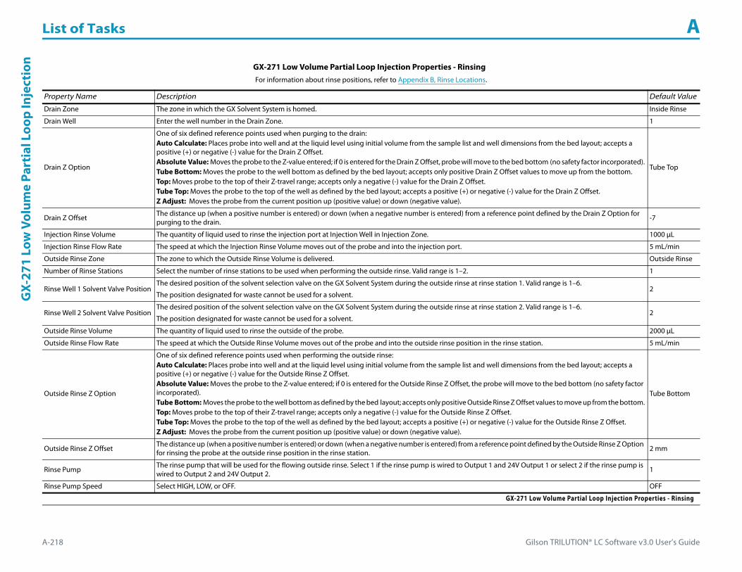
List of Tasks A
A-218 Gilson TRILUTION® LC Software v3.0 User’s Guide
GX-
271
Low
Vol
ume
Part
ial L
oop
Inje
ctio
n
GX-271 Low Volume Partial Loop Injection Properties - Rinsing For information about rinse positions, refer to Appendix B, Rinse Locations.
Property Name Description Default Value
Drain Zone The zone in which the GX Solvent System is homed. Inside Rinse
Drain Well Enter the well number in the Drain Zone. 1
Drain Z Option
One of six defined reference points used when purging to the drain:Auto Calculate: Places probe into well and at the liquid level using initial volume from the sample list and well dimensions from the bed layout; accepts a positive (+) or negative (-) value for the Drain Z Offset.Absolute Value: Moves the probe to the Z-value entered; if 0 is entered for the Drain Z Offset, probe will move to the bed bottom (no safety factor incorporated).Tube Bottom: Moves the probe to the well bottom as defined by the bed layout; accepts only positive Drain Z Offset values to move up from the bottom.Top: Moves probe to the top of their Z-travel range; accepts only a negative (-) value for the Drain Z Offset.Tube Top: Moves the probe to the top of the well as defined by the bed layout; accepts a positive (+) or negative (-) value for the Drain Z Offset.Z Adjust: Moves the probe from the current position up (positive value) or down (negative value).
Tube Top
Drain Z Offset The distance up (when a positive number is entered) or down (when a negative number is entered) from a reference point defined by the Drain Z Option for purging to the drain. -7
Injection Rinse Volume The quantity of liquid used to rinse the injection port at Injection Well in Injection Zone. 1000 μL
Injection Rinse Flow Rate The speed at which the Injection Rinse Volume moves out of the probe and into the injection port. 5 mL/min
Outside Rinse Zone The zone to which the Outside Rinse Volume is delivered. Outside Rinse
Number of Rinse Stations Select the number of rinse stations to be used when performing the outside rinse. Valid range is 1–2. 1
Rinse Well 1 Solvent Valve PositionThe desired position of the solvent selection valve on the GX Solvent System during the outside rinse at rinse station 1. Valid range is 1–6.
The position designated for waste cannot be used for a solvent.2
Rinse Well 2 Solvent Valve PositionThe desired position of the solvent selection valve on the GX Solvent System during the outside rinse at rinse station 2. Valid range is 1–6.
The position designated for waste cannot be used for a solvent.2
Outside Rinse Volume The quantity of liquid used to rinse the outside of the probe. 2000 μL
Outside Rinse Flow Rate The speed at which the Outside Rinse Volume moves out of the probe and into the outside rinse position in the rinse station. 5 mL/min
Outside Rinse Z Option
One of six defined reference points used when performing the outside rinse:Auto Calculate: Places probe into well and at the liquid level using initial volume from the sample list and well dimensions from the bed layout; accepts a positive (+) or negative (-) value for the Outside Rinse Z Offset.Absolute Value: Moves the probe to the Z-value entered; if 0 is entered for the Outside Rinse Z Offset, the probe will move to the bed bottom (no safety factor incorporated).Tube Bottom: Moves the probe to the well bottom as defined by the bed layout; accepts only positive Outside Rinse Z Offset values to move up from the bottom.Top: Moves probe to the top of their Z-travel range; accepts only a negative (-) value for the Outside Rinse Z Offset.Tube Top: Moves the probe to the top of the well as defined by the bed layout; accepts a positive (+) or negative (-) value for the Outside Rinse Z Offset.Z Adjust: Moves the probe from the current position up (positive value) or down (negative value).
Tube Bottom
Outside Rinse Z Offset The distance up (when a positive number is entered) or down (when a negative number is entered) from a reference point defined by the Outside Rinse Z Option for rinsing the probe at the outside rinse position in the rinse station. 2 mm
Rinse Pump The rinse pump that will be used for the flowing outside rinse. Select 1 if the rinse pump is wired to Output 1 and 24V Output 1 or select 2 if the rinse pump is wired to Output 2 and 24V Output 2. 1
Rinse Pump Speed Select HIGH, LOW, or OFF. OFF
GX-271 Low Volume Partial Loop Injection Properties - Rinsing

Gilson TRILUTION® LC Software v3.0 User’s Guide A-219
List of Tasks AG
X-271 Low Volum
e Partial Loop Injection
GX-271 Low Volume Partial Loop Injection - Sequence of StepsThe following is an overview for the sequence of steps.
1 Initialize2 Aspirate3 Inject4 Injection Port Rinse5 Outside Rinse
Initialize1 Move Z to Z Safe Height.2 Set injection valve to INJECT.3 Move to Drain Well in Drain Zone.4 Lower probe into well to Drain Z Option and Drain Z Offset.5 Switch solvent valve to Solvent Valve Position and dispense volume held by transfer tubing at 5 mL/min.6 Move Z to Z Safe Height.
Aspirate1 Switch solvent valve to waste and aspirate Air Gap Volume at Air Gap Flow Rate.2 Move to Sample Well in Sample Zone.3 Lower probe into well to Sample Z Option and Sample Z Offset.4 Aspirate Injection Volume + Extra Volume at Aspirate Flow Rate.5 Move Z to Z Safe Height.
Inject1 Move to Injection Well in Injection Zone.2 Lower probe to Injection Z Option and Injection Z Offset.3 Switch solvent valve to Solvent Valve Position and dispense Extra Volume at Dispense Flow Rate.4 Switch injection valve to LOAD.5 Wait 1.2 sec.6 Dispense Injection Volume + Push Volume at Dispense Flow Rate.7 Wait Injection Equilibration Time.8 Synchronize.9 Switch injection valve to INJECT.

List of Tasks A
A-220 Gilson TRILUTION® LC Software v3.0 User’s Guide
GX-
271
Low
Vol
ume
Part
ial L
oop
Inje
ctio
n Injection Port Rinse1 Switch solvent valve to Solvent Valve Position and dispense volume held by transfer tubing at 5 mL/min.2 Dispense Injection Rinse Volume at Injection Rinse Flow Rate.3 Move Z to Z Safe Height
Outside Rinse1 Move Z to Z Safe Height.2 Move to rinse station/well 1 in Outside Rinse Zone.3 Lower probe into well to Outside Rinse Z Option and Outside Rinse Z Offset.4 Switch Rinse Pump on at Rinse Pump Speed.5 Switch solvent valve to Rinse Well 1 Solvent Valve Position and dispense Outside Rinse Volume at Outside Rinse Flow Rate. If the current solvent valve position
is not the same as the previous solvent valve position, dispense Outside Rinse Volume + 2000 uL + Transfer Tubing volume.6 Switch Rinse Pump off.7 Move Z to Z Safe Height.8 Repeat steps 2–7 for the Number of Rinse Stations, incrementing the rinse station/well for each rinse station.

Gilson TRILUTION® LC Software v3.0 User’s Guide A-221
List of Tasks AG
X-271 Partial Loop Injection
GX-271 Partial Loop InjectionThis task performs a partial loop injection.
For more information about the properties on each tab, refer to:
GX-271 Partial Loop Injection Properties - Main
GX-271 Partial Loop Injection Properties - Rinsing
GX-271 Partial Loop Injection - Sequence of Steps
GX-271 Partial Loop Injection Properties - Main
Property Name Description Default Value
Liquid Handler The liquid handler that the task will affect. Liquid Handler
Pump The pump that the task will affect. Liquid Handler
Injector The injector or injection module that the task will affect. Liquid Handler
GX-271 Partial Loop Injection Properties - Main (Page 1 of 2)
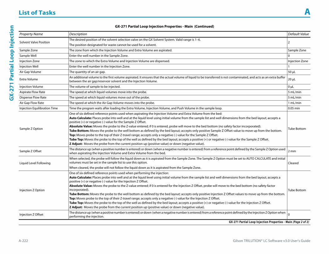
List of Tasks A
A-222 Gilson TRILUTION® LC Software v3.0 User’s Guide
GX-
271
Part
ial L
oop
Inje
ctio
n
Solvent Valve PositionThe desired position of the solvent selection valve on the GX Solvent System. Valid range is 1–6.
The position designated for waste cannot be used for a solvent.2
Sample Zone The zone from which the Injection Volume and Extra Volume are aspirated. Sample Zone
Sample Well Enter the well number in the Sample Zone. 0
Injection Zone The zone to which the Extra Volume and Injection Volume are dispensed. Injection Zone
Injection Well Enter the well number in the Injection Zone. 1
Air Gap Volume The quantity of an air gap. 50 μL
Extra Volume An additional volume to the first volume aspirated. It ensures that the actual volume of liquid to be transferred is not contaminated, and acts as an extra buffer between the air gap/reservoir solvent and the Injection Volume. 20 μL
Injection Volume The volume of sample to be injected. 0 μL
Aspirate Flow Rate The speed at which liquid volumes move into the probe. 5 mL/min
Dispense Flow Rate The speed at which liquid volumes move out of the probe. 5 mL/min
Air Gap Flow Rate The speed at which the Air Gap Volume moves into the probe. 1 mL/min
Injection Equilibration Time Time the program waits after loading the Extra Volume, Injection Volume, and Push Volume in the sample loop. 0.05 min
Sample Z Option
One of six defined reference points used when aspirating the Injection Volume and Extra Volume from the bed:Auto Calculate: Places probe into well and at the liquid level using initial volume from the sample list and well dimensions from the bed layout; accepts a positive (+) or negative (-) value for the Sample Z Offset.Absolute Value: Moves the probe to the Z-value entered; if 0 is entered, probe will move to the bed bottom (no safety factor incorporated).Tube Bottom: Moves the probe to the well bottom as defined by the bed layout; accepts only positive Sample Z Offset value to move up from the bottom.Top: Moves probe to the top of their Z-travel range; accepts only a negative (-) value for the Sample Z Offset.Tube Top: Moves the probe to the top of the well as defined by the bed layout; accepts a positive (+) or negative (-) value for the Sample Z Offset.Z Adjust: Moves the probe from the current position up (positive value) or down (negative value).
Tube Bottom
Sample Z Offset The distance up (when a positive number is entered) or down (when a negative number is entered) from a reference point defined by the Sample Z Option used when aspirating the Injection Volume and Extra Volume from the bed. 2 mm
Liquid Level FollowingWhen selected, the probe will follow the liquid down as it is aspirated from the Sample Zone. The Sample Z Option must be set to AUTO CALCULATE and initial volumes must be set in the sample list to use this option.
When cleared, the probe will not follow the liquid down as it is aspirated from the Sample Zone.Cleared
Injection Z Option
One of six defined reference points used when performing the injection:Auto Calculate: Places probe into well and at the liquid level using initial volume from the sample list and well dimensions from the bed layout; accepts a positive (+) or negative (-) value for the Injection Z Offset.Absolute Value: Moves the probe to the Z-value entered; if 0 is entered for the Injection Z Offset, probe will move to the bed bottom (no safety factor incorporated).Tube Bottom: Moves the probe to the well bottom as defined by the bed layout; accepts only positive Injection Z Offset values to move up from the bottom.Top: Moves probe to the top of their Z-travel range; accepts only a negative (-) value for the Injection Z Offset.Tube Top: Moves the probe to the top of the well as defined by the bed layout; accepts a positive (+) or negative (-) value for the Injection Z Offset.Z Adjust: Moves the probe from the current position up (positive value) or down (negative value).
Tube Bottom
Injection Z Offset The distance up (when a positive number is entered) or down (when a negative number is entered) from a reference point defined by the Injection Z Option when performing the injection. 0
GX-271 Partial Loop Injection Properties - Main (Continued)
Property Name Description Default Value
GX-271 Partial Loop Injection Properties - Main (Page 2 of 2)

Gilson TRILUTION® LC Software v3.0 User’s Guide A-223
List of Tasks AG
X-271 Partial Loop Injection
GX-271 Partial Loop Injection Properties - Rinsing For information about rinse positions, refer to Appendix B, Rinse Locations.
Property Name Description Default Value
Drain Zone The zone in which the GX Solvent System is homed. Inside Rinse
Drain Well Enter the well number in the Drain Zone. 1
Drain Z Option
One of six defined reference points used when purging to the drain:Auto Calculate: Places probe into well and at the liquid level using initial volume from the sample list and well dimensions from the bed layout; accepts a positive (+) or negative (-) value for the Drain Z Offset.Absolute Value: Moves the probe to the Z-value entered; if 0 is entered for the Drain Z Offset, probe will move to the bed bottom (no safety factor incorporated).Tube Bottom: Moves the probe to the well bottom as defined by the bed layout; accepts only positive Drain Z Offset values to move up from the bottom.Top: Moves probe to the top of their Z-travel range; accepts only a negative (-) value for the Drain Z Offset.Tube Top: Moves the probe to the top of the well as defined by the bed layout; accepts a positive (+) or negative (-) value for the Drain Z Offset.Z Adjust: Moves the probe from the current position up (positive value) or down (negative value).
Tube Top
Drain Z Offset The distance up (when a positive number is entered) or down (when a negative number is entered) from a reference point defined by the Drain Z Option for purging to the drain. -7
Injection Rinse Volume The quantity of liquid used to rinse the injection port at Injection Well in Injection Zone. 1000 μL
Injection Rinse Flow Rate The speed at which the Injection Rinse Volume moves out of the probe and into the injection port. 5 mL/min
Outside Rinse Zone The zone to which the Outside Rinse Volume is delivered.Outside Rinse
Number of Rinse Stations Select the number of rinse stations to be used when performing the outside rinse. Valid range is 1–2. 1
Rinse Well 1 Solvent Valve PositionThe desired position of the solvent selection valve on the GX Solvent System during the outside rinse at rinse station 1. Valid range is 1–6.
The position designated for waste cannot be used for a solvent.2
Rinse Well 2 Solvent Valve PositionThe desired position of the solvent selection valve on the GX Solvent System during the outside rinse at rinse station 2. Valid range is 1–6.
The position designated for waste cannot be used for a solvent.2
Outside Rinse Volume The quantity of liquid used to rinse the outside of the probe. 2000 μL
Outside Rinse Flow Rate The speed at which the Outside Rinse Volume moves out of the probe and into the outside rinse position in the rinse station. 5 mL/min
Outside Rinse Z Option
One of six defined reference points used when performing the outside rinse:Auto Calculate: Places probe into well and at the liquid level using initial volume from the sample list and well dimensions from the bed layout; accepts a positive (+) or negative (-) value for the Outside Rinse Z Offset.Absolute Value: Moves the probe to the Z-value entered; if 0 is entered for the Outside Rinse Z Offset, the probe will move to the bed bottom (no safety factor incorporated).Tube Bottom: Moves the probe to the well bottom as defined by the bed layout; accepts only positive Outside Rinse Z Offset values to move up from the bottom.Top: Moves probe to the top of their Z-travel range; accepts only a negative (-) value for the Outside Rinse Z Offset.Tube Top: Moves the probe to the top of the well as defined by the bed layout; accepts a positive (+) or negative (-) value for the Outside Rinse Z Offset.Z Adjust: Moves the probe from the current position up (positive value) or down (negative value).
Tube Bottom
Outside Rinse Z Offset The distance up (when a positive number is entered) or down (when a negative number is entered) from a reference point defined by the Outside Rinse Z Option for rinsing the probe at the outside rinse position in the rinse station. 2 mm
Rinse Pump The rinse pump that will be used for the flowing outside rinse. Select 1 if the rinse pump is wired to Output 1 and 24V Output 1 or select 2 if the rinse pump is wired to Output 2 and 24V Output 2. 1
Rinse Pump Speed Select HIGH, LOW, or OFF. OFF
GX-271 Partial Loop Injection Properties - Rinsing

List of Tasks A
A-224 Gilson TRILUTION® LC Software v3.0 User’s Guide
GX-
271
Part
ial L
oop
Inje
ctio
n GX-271 Partial Loop Injection - Sequence of StepsThe following is an overview for the sequence of steps.
1 Initialize2 Aspirate3 Inject4 Injection Port Rinse5 Outside Rinse
Initialize1 Move Z to Z Safe Height.2 Set injection valve to INJECT.3 Move to Drain Well in Drain Zone.4 Lower probe into well to Drain Z Option and Drain Z Offset.5 Switch solvent valve to Solvent Valve Position and dispense volume held by transfer tubing at 5 mL/min.6 Move Z to Z Safe Height.
Aspirate1 Switch solvent valve to waste and aspirate Air Gap Volume at Air Gap Flow Rate.2 Move to Sample Well in Sample Zone.3 Lower probe into well to Sample Z Option and Sample Z Offset.4 Aspirate Injection Volume + Extra Volume at Aspirate Flow Rate.5 Move Z to Z Safe Height.
Inject1 Move to Injection Well in Injection Zone.2 Lower probe to Injection Z Option and Injection Z Offset.3 Switch solvent valve to Solvent Valve Position and dispense Extra Volume at Dispense Flow Rate.4 Switch injection valve to LOAD.5 Wait 1.2 sec.6 Dispense Injection Volume at Dispense Flow Rate.7 Wait Injection Equilibration Time.8 Synchronize.9 Switch injection valve to INJECT.

Gilson TRILUTION® LC Software v3.0 User’s Guide A-225
List of Tasks AG
X-271 Partial Loop Injection
Injection Port Rinse1 Switch solvent valve to Solvent Valve Position and dispense volume held by transfer tubing at 5 mL/min.2 Dispense Injection Rinse Volume at Injection Rinse Flow Rate.3 Move Z to Z Safe Height
Outside Rinse1 Move Z to Z Safe Height.2 Move to rinse station/well 1 in Outside Rinse Zone.3 Lower probe into well to Outside Rinse Z Option and Outside Rinse Z Offset.4 Switch Rinse Pump on at Rinse Pump Speed.5 Switch solvent valve to Rinse Well 1 Solvent Valve Position and dispense Outside Rinse Volume at Outside Rinse Flow Rate. If the current solvent valve position
is not the same as the previous solvent valve position, dispense Outside Rinse Volume + 2000 uL + Transfer Tubing volume.6 Switch Rinse Pump off.7 Move Z to Z Safe Height.8 Repeat steps 2–7 for the Number of Rinse Stations, incrementing the rinse station/well for each rinse station.

List of Tasks A
A-226 Gilson TRILUTION® LC Software v3.0 User’s Guide
GX-
271
Prep
Inje
ctio
n w
ith
Colle
ctio
n GX-271 Prep Injection with CollectionThis task performs a partial loop injection using a push volume from the reservoir to push the injection volume into the sample loop and includes a rinse of the fraction collection valve.
For more information about the properties on each tab, refer to:
GX-271 Prep Injection with Collection Properties - Main
GX-271 Prep Injection with Collection Properties - Rinsing
GX-271 Prep Injection with Collection - Sequence of Steps
GX-271 Prep Injection with Collection Properties - Main
Property Name Description Default Value
Liquid Handler The liquid handler that the task will affect. Liquid Handler
Pump The pump that the task will affect. Liquid Handler
Injector The injector or injection module that the task will affect. Liquid Handler
GX-271 Prep Injection with Collection Properties - Main (Page 1 of 2)

Gilson TRILUTION® LC Software v3.0 User’s Guide A-227
List of Tasks AG
X-271 Prep Injection with Collection
Solvent Valve PositionThe desired position of the solvent selection valve on the GX Solvent System. Valid range is 1–6.
The position designated for waste cannot be used for a solvent.2
Sample Zone The zone from which the Injection Volume and Extra Volume are aspirated. Sample Zone
Sample Well Enter the well number in the Sample Zone. 0
Injection Zone The zone to which the Push Volume and Injection Volume are dispensed. Injection Zone
Injection Well Enter the well number in the Injection Zone. 1
Air Gap Volume The quantity of an air gap. 50 μL
Push Volume A volume of reservoir solvent used to push the injection volume into the sample loop. 20 μL
Injection Volume The volume of sample to be injected. 0 μL
Aspirate Flow Rate The speed at which liquid volumes move into the probe. 5 mL/min
Dispense Flow Rate The speed at which liquid volumes move out of the probe. 5 mL/min
Air Gap Flow Rate The speed at which the Air Gap Volume moves into the probe. 1 mL/min
Injection Equilibration Time Time the program waits after loading the Extra Volume, Injection Volume, and Push Volume in the sample loop. 0.05 min
Sample Z Option
One of six defined reference points used when aspirating the Injection Volume and Extra Volume from the bed:Auto Calculate: Places probe into well and at the liquid level using initial volume from the sample list and well dimensions from the bed layout; accepts a positive (+) or negative (-) value for the Sample Z Offset.Absolute Value: Moves the probe to the Z-value entered; if 0 is entered, probe will move to the bed bottom (no safety factor incorporated).Tube Bottom: Moves the probe to the well bottom as defined by the bed layout; accepts only positive Sample Z Offset value to move up from the bottom.Top: Moves probe to the top of their Z-travel range; accepts only a negative (-) value for the Sample Z Offset.Tube Top: Moves the probe to the top of the well as defined by the bed layout; accepts a positive (+) or negative (-) value for the Sample Z Offset.Z Adjust: Moves the probe from the current position up (positive value) or down (negative value).
Tube Bottom
Sample Z Offset The distance up (when a positive number is entered) or down (when a negative number is entered) from a reference point defined by the Sample Z Option used when aspirating the Injection Volume and Extra Volume from the bed. 2
Liquid Level FollowingWhen selected, the probe will follow the liquid down as it is aspirated from the Sample Zone. The Sample Z Option must be set to AUTO CALCULATE and initial volumes must be set in the sample list to use this option.
When cleared, the probe will not follow the liquid down as it is aspirated from the Sample Zone.Cleared
Injection Z Option
One of six defined reference points used when performing the injection:Auto Calculate: Places probe into well and at the liquid level using initial volume from the sample list and well dimensions from the bed layout; accepts a positive (+) or negative (-) value for the Injection Z Offset.Absolute Value: Moves the probe to the Z-value entered; if 0 is entered, probe will move to the bed bottom (no safety factor incorporated).Tube Bottom: Moves the probe to the well bottom as defined by the bed layout; accepts only positive Injection Z Offset values to move up from the bottom.Top: Moves probe to the top of their Z-travel range; accepts only a negative (-) value for the Injection Z Offset.Tube Top: Moves the probe to the top of the well as defined by the bed layout; accepts a positive (+) or negative (-) value for the Injection Z Offset.Z Adjust: Moves the probe from the current position up (positive value) or down (negative value).
Tube Bottom
Injection Z Offset The distance up (when a positive number is entered) or down (when a negative number is entered) from a reference point defined by the Injection Z Option when performing the injection. 0
GX-271 Prep Injection with Collection Properties - Main (Continued)
Property Name Description Default Value
GX-271 Prep Injection with Collection Properties - Main (Page 2 of 2)

List of Tasks A
A-228 Gilson TRILUTION® LC Software v3.0 User’s Guide
GX-
271
Prep
Inje
ctio
n w
ith
Colle
ctio
n
GX-271 Prep Injection with Collection Properties - Rinsing For information about rinse positions, refer to Appendix B, Rinse Locations.
Property Name Description Default Value
Drain Zone The zone in which the GX Solvent System is homed. Inside Rinse
Drain Well Enter the well number in the Drain Zone. 1
Drain Z Option
One of six defined reference points used when purging to the drain:Auto Calculate: Places probe into well and at the liquid level using initial volume from the sample list and well dimensions from the bed layout; accepts a positive (+) or negative (-) value for the Drain Z Offset.Absolute Value: Moves the probe to the Z-value entered; if 0 is entered, probe will move to the bed bottom (no safety factor incorporated).Tube Bottom: Moves the probe to the well bottom as defined by the bed layout; accepts only positive Drain Z Offset values to move up from the bottom.Top: Moves probe to the top of their Z-travel range; accepts only a negative (-) value for the Drain Z Offset.Tube Top: Moves the probe to the top of the well as defined by the bed layout; accepts a positive (+) or negative (-) value for the Drain Z Offset.Z Adjust: Moves the probe from the current position up (positive value) or down (negative value).
Tube Top
Drain Z Offset The distance up (when a positive number is entered) or down (when a negative number is entered) from a reference point defined by the Drain Z Option for purging to the drain. -7
Injection Rinse Volume The quantity of liquid used to rinse the injection port at Injection Well in Injection Zone. 1000 μL
Injection Rinse Flow Rate The speed at which the Injection Rinse Volume moves out of the probe and into the injection port. 5 mL/min
Outside Rinse Zone The zone to which the Outside Rinse Volume is delivered. Outside Rinse
Number of Rinse Stations Select the number of rinse stations to be used when performing the outside rinse. Valid range is 1–2. 2
Rinse Well 1 Solvent Valve PositionThe desired position of the solvent selection valve on the GX Solvent System during the outside rinse at rinse station 1. Valid range is 1–6.
The position designated for waste cannot be used for a solvent.2
Rinse Well 2 Solvent Valve PositionThe desired position of the solvent selection valve on the GX Solvent System during the outside rinse at rinse station 2. Valid range is 1–6.
The position designated for waste cannot be used for a solvent.2
Outside Rinse Volume The quantity of liquid used to rinse the outside of the probe. 2000 μL
Outside Rinse Flow Rate The speed at which the Outside Rinse Volume moves out of the probe and into the outside rinse position in the rinse station. 5 mL/min
Outside Rinse Z Option
One of six defined reference points used when performing the outside rinse:Auto Calculate: Places probe into well and at the liquid level using initial volume from the sample list and well dimensions from the bed layout; accepts a positive (+) or negative (-) value for the Outside Rinse Z Offset.Absolute Value: Moves the probe to the Z-value entered; if 0 is entered, the probe will move to the bed bottom (no safety factor incorporated).Tube Bottom: Moves the probe to the well bottom as defined by the bed layout; accepts only positive Outside Rinse Z Offset values to move up from the bottom.Top: Moves probe to the top of their Z-travel range; accepts only a negative (-) value for the Outside Rinse Z Offset.Tube Top: Moves the probe to the top of the well as defined by the bed layout; accepts a positive (+) or negative (-) value for the Outside Rinse Z Offset.Z Adjust: Moves the probe from the current position up (positive value) or down (negative value).
Tube Bottom
Outside Rinse Z Offset The distance up (when a positive number is entered) or down (when a negative number is entered) from a reference point defined by the Outside Rinse Z Option for rinsing the probe at the outside rinse position in the rinse station. 2 mm
Rinse Pump The rinse pump that will be used for the flowing outside rinse. Select 1 if the rinse pump is wired to Output 1 and 24V Output 1 or select 2 if the rinse pump is wired to Output 2 and 24V Output 2. 1
Rinse Pump Speed Select HIGH, LOW, or OFF. OFF
GX-271 Prep Injection with Collection Properties - Rinsing

Gilson TRILUTION® LC Software v3.0 User’s Guide A-229
List of Tasks AG
X-271 Prep Injection with Collection
GX-271 Prep Injection with Collection - Sequence of StepsThe following is an overview for the sequence of steps.
1 Initialize2 Aspirate3 Inject4 Injection Port Rinse5 Outside Rinse
Initialize1 Move Z to Z Safe Height.2 Set injection valve to INJECT.3 Move to Drain Well in Drain Zone.4 Lower probe into well to Drain Z Option and Drain Z Offset.5 Switch fraction collection valve to COLLECT for 2 seconds.6 Lower probe into well to Drain Z Option and Drain Z Offset.7 Switch solvent valve to Solvent Valve Position and dispense volume held by transfer tubing at 5 mL/min.8 Move Z to Z Safe Height.
Aspirate1 Switch solvent valve to waste and aspirate Air Gap Volume at Air Gap Flow Rate.2 Move to Sample Well in Sample Zone.3 Lower probe into well to Sample Z Option and Sample Z Offset.4 Aspirate Injection Volume at Aspirate Flow Rate.5 Move Z to Z Safe Height.

List of Tasks A
A-230 Gilson TRILUTION® LC Software v3.0 User’s Guide
GX-
271
Prep
Inje
ctio
n w
ith
Colle
ctio
n Inject1 Move to Injection Well in Injection Zone.2 Lower probe into well to Injection Z Option and Injection Z Offset.3 Switch injection valve to LOAD.4 Wait 1.2 sec.5 Switch solvent valve to Solvent Valve Position and dispense Injection Volume + Push Volume at Dispense Flow Rate.6 Wait Injection Equilibration Time.7 Synchronize.8 Switch injection valve to INJECT.
Injection Port Rinse1 Switch solvent valve to Solvent Valve Position and dispense volume held by transfer tubing at 5 mL/min.2 Dispense Injection Rinse Volume at Injection Rinse Flow Rate.3 Move Z to Z Safe Height
Outside Rinse1 Move Z to Z Safe Height.2 Move to rinse station/well 1 in Outside Rinse Zone.3 Lower probe into well to Outside Rinse Z Option and Outside Rinse Z Offset.4 Switch Rinse Pump on at Rinse Pump Speed.5 Switch solvent valve to Rinse Well 1 Solvent Valve Position and dispense Outside Rinse Volume at Outside Rinse Flow Rate. If the current solvent valve position
is not the same as the previous solvent valve position, dispense Outside Rinse Volume + 2000 uL + Transfer Tubing volume.6 Switch Rinse Pump off.7 Move Z to Z Safe Height.8 Repeat steps 2–7 for the Number of Rinse Stations, incrementing the rinse station/well for each rinse station.

Gilson TRILUTION® LC Software v3.0 User’s Guide A-231
List of Tasks AG
X-271 Prep Injection with Collection H
igh Mount
GX-271 Prep Injection with Collection High MountThis task is used when doing injection and fraction collection on the same bed. It rinses the probe and then it performs a partial loop injection using a push volume from the reservoir to push the injection volume into the sample loop. It includes a rinse of the fraction collection valve for a user-defined duration after the injection.
For more information about the properties on each tab, refer to:
GX-271 Prep Injection with Collection High Mount Properties - Main
GX-271 Prep Injection with Collection High Mount Properties - Rinsing
GX-271 Prep Injection with Collection High Mount - Sequence of Steps
GX-271 Prep Injection with Collection High Mount Properties - Main
Property Name Description Default Value
Liquid Handler The liquid handler that the task will affect. Liquid Handler
Pump The pump that the task will affect. Liquid Handler
Injector The injector or injection module that the task will affect. Liquid Handler
GX-271 Prep Injection with Collection High Mount Properties - Main (Page 1 of 2)

List of Tasks A
A-232 Gilson TRILUTION® LC Software v3.0 User’s Guide
GX-
271
Prep
Inje
ctio
n w
ith
Colle
ctio
n H
igh
Mou
nt
Solvent Valve PositionThe desired position of the solvent selection valve on the GX Solvent System. Valid range is 1–6.
The position designated for waste cannot be used for a solvent.2
Sample Zone The zone from which the Injection Volume and Extra Volume are aspirated. Sample Zone
Sample Well Enter the well number in the Sample Zone. 0
Injection Zone The zone to which the Push Volume and Injection Volume are dispensed. Injection Zone
Injection Well Enter the well number in the Injection Zone. 1
Air Gap Volume The quantity of an air gap. 50 μL
Push Volume A volume of reservoir solvent used to push the injection volume into the sample loop. 20 μL
Injection Volume The volume of sample to be injected. 0 μL
Aspirate Flow Rate The speed at which liquid volumes move into the probe. 5 mL/min
Dispense Flow Rate The speed at which liquid volumes move out of the probe. 5 mL/min
Air Gap Flow Rate The speed at which the Air Gap Volume moves into the probe. 1 mL/min
Injection Equilibration Time Time the program waits after loading the Extra Volume, Injection Volume, and Push Volume in the sample loop. 0.05 min
Sample Z Option
One of six defined reference points used when aspirating the Injection Volume and Extra Volume from the bed:Auto Calculate: Places probe into well and at the liquid level using initial volume from the sample list and well dimensions from the bed layout; accepts a positive (+) or negative (-) value for the Sample Z Offset.Absolute Value: Moves the probe to the Z-value entered; if 0 is entered, probe will move to the bed bottom (no safety factor incorporated).Tube Bottom: Moves the probe to the well bottom as defined by the bed layout; accepts only positive Sample Z Offset value to move up from the bottom.Top: Moves probe to the top of their Z-travel range; accepts only a negative (-) value for the Sample Z Offset.Tube Top: Moves the probe to the top of the well as defined by the bed layout; accepts a positive (+) or negative (-) value for the Sample Z Offset.Z Adjust: Moves the probe from the current position up (positive value) or down (negative value).
Tube Bottom
Sample Z Offset The distance up (when a positive number is entered) or down (when a negative number is entered) from a reference point defined by the Sample Z Option used when aspirating the Injection Volume and Extra Volume from the bed. 2
Liquid Level FollowingWhen selected, the probe will follow the liquid down as it is aspirated from the Sample Zone. The Sample Z Option must be set to AUTO CALCULATE and initial volumes must be set in the sample list to use this option.
When cleared, the probe will not follow the liquid down as it is aspirated from the Sample Zone.Cleared
Injection Z Option
One of six defined reference points used when performing the injection:Auto Calculate: Places probe into well and at the liquid level using initial volume from the sample list and well dimensions from the bed layout; accepts a positive (+) or negative (-) value for the Injection Z Offset.Absolute Value: Moves the probe to the Z-value entered; if 0 is entered, probe will move to the bed bottom (no safety factor incorporated).Tube Bottom: Moves the probe to the well bottom as defined by the bed layout; accepts only positive Injection Z Offset values to move up from the bottom.Top: Moves probe to the top of their Z-travel range; accepts only a negative (-) value for the Injection Z Offset.Tube Top: Moves the probe to the top of the well as defined by the bed layout; accepts a positive (+) or negative (-) value for the Injection Z Offset.Z Adjust: Moves the probe from the current position up (positive value) or down (negative value).
Tube Bottom
Injection Z Offset The distance up (when a positive number is entered) or down (when a negative number is entered) from a reference point defined by the Injection Z Option when performing the injection. 0
GX-271 Prep Injection with Collection High Mount Properties - Main (Continued)
Property Name Description Default Value
GX-271 Prep Injection with Collection High Mount Properties - Main (Page 2 of 2)

Gilson TRILUTION® LC Software v3.0 User’s Guide A-233
List of Tasks AG
X-271 Prep Injection with Collection H
igh Mount
GX-271 Prep Injection with Collection High Mount Properties - Rinsing For information about rinse positions, refer to Appendix B, Rinse Locations.
Property Name Description Default Value
Inside Rinse Zone The zone to which the Rinse Volume is delivered. Inside Rinse
Inside Rinse Well Enter the well number in the Inside Rinse Zone. 1
Rinse Volume The quantity of liquid used to rinse the inside of the probe. 1000 μL
Rinse Flow Rate The speed at which the Rinse Volume moves out of the probe and into the outside rinse position in the rinse station. 5 mL/min
Inside Rinse Z Option
One of six defined reference points used when performing the inside rinse:Auto Calculate: Places probe into well and at the liquid level using initial volume from the sample list and well dimensions from the bed layout; accepts a positive (+) or negative (-) value for the Inside Rinse Z Offset.Absolute Value: Moves the probe to the Z-value entered; if 0 is entered for the Inside Rinse Z Offset, the probe will move to the bed bottom (no safety factor incorporated).Tube Bottom: Moves the probe to the well bottom as defined by the bed layout; accepts only positive Inside Rinse Z Offset values to move up from the bottom.Top: Moves probe to the top of their Z-travel range; accepts only a negative (-) value for the Inside Rinse Z Offset.Tube Top: Moves the probe to the top of the well as defined by the bed layout; accepts a positive (+) or negative (-) value for the Inside Rinse Z Offset.Z Adjust: Moves the probe from the current position up (positive value) or down (negative value).
Tube Top
Inside Rinse Z Offset The distance up (when a positive number is entered) or down (when a negative number is entered) from a reference point defined by the Inside Rinse Z Option for rinsing the probe at the inside rinse position in the rinse station. -7 mm
Drain Zone The zone in which the GX Solvent System is homed. Inside Rinse
Drain Well Enter the well number in the Drain Zone. 1
Drain Z Option
One of six defined reference points used when purging to the drain:Auto Calculate: Places probe into well and at the liquid level using initial volume from the sample list and well dimensions from the bed layout; accepts a positive (+) or negative (-) value for the Drain Z Offset.Absolute Value: Moves the probe to the Z-value entered; if 0 is entered, probe will move to the bed bottom (no safety factor incorporated).Tube Bottom: Moves the probe to the well bottom as defined by the bed layout; accepts only positive Drain Z Offset values to move up from the bottom.Top: Moves probe to the top of their Z-travel range; accepts only a negative (-) value for the Drain Z Offset.Tube Top: Moves the probe to the top of the well as defined by the bed layout; accepts a positive (+) or negative (-) value for the Drain Z Offset.Z Adjust: Moves the probe from the current position up (positive value) or down (negative value).
Tube Top
Drain Z Offset The distance up (when a positive number is entered) or down (when a negative number is entered) from a reference point defined by the Drain Z Option for purging to the drain. -7
Fraction Collection Valve Rinse Time After the valve switches to COLLECT, the length of time the valve is rinsed before switching the valve back to DIVERT. 0.1 min
Injection Rinse Volume The quantity of liquid used to rinse the injection port at Injection Well in Injection Zone. 1000 μL
Injection Rinse Flow Rate The speed at which the Injection Rinse Volume moves out of the probe and into the injection port. 5 mL/min
Outside Rinse Zone The zone to which the Outside Rinse Volume is delivered. Outside Rinse
Number of Rinse Stations Select the number of rinse stations to be used when performing the outside rinse. Valid range is 1–2. 2
Rinse Well 1 Solvent Valve PositionThe desired position of the solvent selection valve on the GX Solvent System during the outside rinse at rinse station 1. Valid range is 1–6.
The position designated for waste cannot be used for a solvent.2
Rinse Well 2 Solvent Valve PositionThe desired position of the solvent selection valve on the GX Solvent System during the outside rinse at rinse station 2. Valid range is 1–6.
The position designated for waste cannot be used for a solvent.2
Outside Rinse Volume The quantity of liquid used to rinse the outside of the probe. 2000 μL
GX-271 Prep Injection with Collection High Mount Properties - Rinsing (Page 1 of 2)

List of Tasks A
A-234 Gilson TRILUTION® LC Software v3.0 User’s Guide
GX-
271
Prep
Inje
ctio
n w
ith
Colle
ctio
n H
igh
Mou
nt
GX-271 Prep Injection with Collection High Mount - Sequence of StepsThe following is an overview for the sequence of steps.
1 Initialize2 Aspirate3 Inject4 Injection Port Rinse5 Outside Rinse6 Fraction Collection Valve Flush
Outside Rinse Flow Rate The speed at which the Outside Rinse Volume moves out of the probe and into the outside rinse position in the rinse station. 5 mL/min
Outside Rinse Z Option
One of six defined reference points used when performing the outside rinse:Auto Calculate: Places probe into well and at the liquid level using initial volume from the sample list and well dimensions from the bed layout; accepts a positive (+) or negative (-) value for the Outside Rinse Z Offset.Absolute Value: Moves the probe to the Z-value entered; if 0 is entered, the probe will move to the bed bottom (no safety factor incorporated).Tube Bottom: Moves the probe to the well bottom as defined by the bed layout; accepts only positive Outside Rinse Z Offset values to move up from the bottom.Top: Moves probe to the top of their Z-travel range; accepts only a negative (-) value for the Outside Rinse Z Offset.Tube Top: Moves the probe to the top of the well as defined by the bed layout; accepts a positive (+) or negative (-) value for the Outside Rinse Z Offset.Z Adjust: Moves the probe from the current position up (positive value) or down (negative value).
Tube Bottom
Outside Rinse Z Offset The distance up (when a positive number is entered) or down (when a negative number is entered) from a reference point defined by the Outside Rinse Z Option for rinsing the probe at the outside rinse position in the rinse station. 2 mm
Rinse Pump The rinse pump that will be used for the flowing outside rinse. Select 1 if the rinse pump is wired to Output 1 and 24V Output 1 or select 2 if the rinse pump is wired to Output 2 and 24V Output 2. 1
Rinse Pump Speed Select HIGH, LOW, or OFF. OFF
GX-271 Prep Injection with Collection High Mount Properties - Rinsing (Continued)For information about rinse positions, refer to Appendix B, Rinse Locations.
Property Name Description Default Value
GX-271 Prep Injection with Collection High Mount Properties - Rinsing (Page 2 of 2)
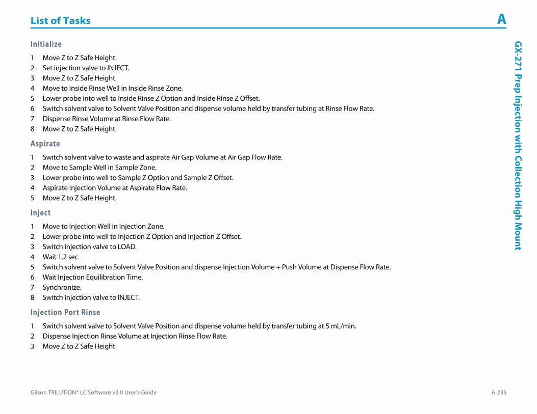
Gilson TRILUTION® LC Software v3.0 User’s Guide A-235
List of Tasks AG
X-271 Prep Injection with Collection H
igh Mount
Initialize1 Move Z to Z Safe Height.2 Set injection valve to INJECT.3 Move Z to Z Safe Height.4 Move to Inside Rinse Well in Inside Rinse Zone.5 Lower probe into well to Inside Rinse Z Option and Inside Rinse Z Offset.6 Switch solvent valve to Solvent Valve Position and dispense volume held by transfer tubing at Rinse Flow Rate.7 Dispense Rinse Volume at Rinse Flow Rate.8 Move Z to Z Safe Height.
Aspirate1 Switch solvent valve to waste and aspirate Air Gap Volume at Air Gap Flow Rate.2 Move to Sample Well in Sample Zone.3 Lower probe into well to Sample Z Option and Sample Z Offset.4 Aspirate Injection Volume at Aspirate Flow Rate.5 Move Z to Z Safe Height.
Inject1 Move to Injection Well in Injection Zone.2 Lower probe into well to Injection Z Option and Injection Z Offset.3 Switch injection valve to LOAD.4 Wait 1.2 sec.5 Switch solvent valve to Solvent Valve Position and dispense Injection Volume + Push Volume at Dispense Flow Rate.6 Wait Injection Equilibration Time.7 Synchronize.8 Switch injection valve to INJECT.
Injection Port Rinse1 Switch solvent valve to Solvent Valve Position and dispense volume held by transfer tubing at 5 mL/min.2 Dispense Injection Rinse Volume at Injection Rinse Flow Rate.3 Move Z to Z Safe Height

List of Tasks A
A-236 Gilson TRILUTION® LC Software v3.0 User’s Guide
GX-
271
Prep
Inje
ctio
n w
ith
Colle
ctio
n H
igh
Mou
nt Outside Rinse1 Move Z to Z Safe Height.2 Move to rinse station/well 1 in Outside Rinse Zone.3 Lower probe into well to Outside Rinse Z Option and Outside Rinse Z Offset.4 Switch Rinse Pump on at Rinse Pump Speed.5 Switch solvent valve to Rinse Well 1 Solvent Valve Position and dispense Outside Rinse Volume at Outside Rinse Flow Rate. If the current solvent valve position
is not the same as the previous solvent valve position, dispense Outside Rinse Volume + 2000 uL + Transfer Tubing volume.6 Switch Rinse Pump off.7 Move Z to Z Safe Height.8 Repeat steps 2–7 for the Number of Rinse Stations, incrementing the rinse station/well for each rinse station.
Fraction Collection Valve Flush1 Move Z to Z Safe Height.2 Move to Drain Well in Drain Zone.3 Lower probe into well to Drain Z Option and Drain Z Offset.4 Switch fraction collection valve to COLLECT for Fraction Collection Valve Rinse Time then switch the fraction collection valve to DIVERT.5 Move Z to Z Safe Height.

Gilson TRILUTION® LC Software v3.0 User’s Guide A-237
List of Tasks AG
X-271 Total Loop Injection
GX-271 Total Loop InjectionThis task performs a total loop injection.
For more information about the properties on each tab, refer to:
GX-271 Total Loop Injection Properties - Main
GX-271 Total Loop Injection Properties - Rinsing
GX-271 Total Loop Injection - Sequence of Steps
GX-271 Total Loop Injection Properties - Main
Property Name Description Default Value
Liquid Handler The liquid handler that the task will affect. Liquid Handler
Pump The pump that the task will affect. Liquid Handler
Injector The injector or injection module that the task will affect. Liquid Handler
GX-271 Total Loop Injection Properties - Main (Page 1 of 3)

List of Tasks A
A-238 Gilson TRILUTION® LC Software v3.0 User’s Guide
GX-
271
Tota
l Loo
p In
ject
ion
Solvent Valve PositionThe desired position of the solvent selection valve on the GX Solvent System. Valid range is 1–6.
The position designated for waste cannot be used for a solvent.2
Sample Zone The zone from which the Injection Volume and Extra Volume are aspirated. Sample Zone
Sample Well Enter the well number in the Sample Zone. 0
Injection Zone The zone to which the Extra Volume and Loop Volume are dispensed. Injection Zone
Injection Well Enter the well number in the Injection Zone. 1
Air Gap Volume The quantity of an air gap. 50 μL
Extra Volume An additional volume to the first volume aspirated. It ensures that the actual volume of liquid to be transferred is not contaminated, and acts as an extra buffer between the air gap/reservoir solvent and the Injection Volume. 1000 μL
Loop Volume The capacity of the installed sample loop. 0 μL
Aspirate Flow Rate The speed at which liquid volumes move into the probe. 5 mL/min
Dispense Flow Rate The speed at which liquid volumes move out of the probe. 5 mL/min
Air Gap Flow Rate The speed at which the Air Gap Volume moves into the probe. 1 mL/min
Injection Equilibration Time The time the program waits after loading the Extra Volume, Injection Volume, and Push Volume in the sample loop. 0.05 min
Sample Z Option
One of six defined reference points used when aspirating the Injection Volume and Extra Volume from the bed:Auto Calculate: Places probe into well and at the liquid level using initial volume from the sample list and well dimensions from the bed layout; accepts a positive (+) or negative (-) value for the Sample Z Offset.Absolute Value: Moves the probe to the Z-value entered; if 0 is entered, probe will move to the bed bottom (no safety factor incorporated).Tube Bottom: Moves the probe to the well bottom as defined by the bed layout; accepts only positive Sample Z Offset value to move up from the bottom.Top: Moves probe to the top of their Z-travel range; accepts only a negative (-) value for the Sample Z Offset.Tube Top: Moves the probe to the top of the well as defined by the bed layout; accepts a positive (+) or negative (-) value for the Sample Z Offset.Z Adjust: Moves the probe from the current position up (positive value) or down (negative value).
Tube Bottom
Sample Z Offset The distance up (when a positive number is entered) or down (when a negative number is entered) from a reference point defined by the Sample Z Option used when aspirating the Injection Volume and Extra Volume from the bed. 2 mm
Liquid Level FollowingWhen selected, the probe will follow the liquid down as it is aspirated from the Sample Zone. The Sample Z Option must be set to AUTO CALCULATE and initial volumes must be set in the sample list to use this option.
When cleared, the probe will not follow the liquid down as it is aspirated from the Sample Zone.Cleared
GX-271 Total Loop Injection Properties - Main (Continued)
Property Name Description Default Value
GX-271 Total Loop Injection Properties - Main (Page 2 of 3)

Gilson TRILUTION® LC Software v3.0 User’s Guide A-239
List of Tasks AG
X-271 Total Loop Injection
Injection Z Option
One of six defined reference points used when performing the injection:Auto Calculate: Places probe into well and at the liquid level using initial volume from the sample list and well dimensions from the bed layout; accepts a positive (+) or negative (-) value for the Injection Z Offset.Absolute Value: Moves the probe to the Z-value entered; if 0 is entered for the Injection Z Offset, probe will move to the bed bottom (no safety factor incorporated).Tube Bottom: Moves the probe to the well bottom as defined by the bed layout; accepts only positive Injection Z Offset values to move up from the bottom.Top: Moves probe to the top of their Z-travel range; accepts only a negative (-) value for the Injection Z Offset.Tube Top: Moves the probe to the top of the well as defined by the bed layout; accepts a positive (+) or negative (-) value for the Injection Z Offset.Z Adjust: Moves the probe from the current position up (positive value) or down (negative value).
Tube Bottom
Injection Z Offset The distance up (when a positive number is entered) or down (when a negative number is entered) from a reference point defined by the Injection Z Option when performing the injection.
0
GX-271 Total Loop Injection Properties - Rinsing For information about rinse positions, refer to Appendix B, Rinse Locations.
Property Name Description Default Value
Drain Zone The zone in which the GX Solvent System is homed. Inside Rinse
Drain Well Enter the well number in the Drain Zone. 1
Drain Z Option
One of six defined reference points used when purging to the drain:Auto Calculate: Places probe into well and at the liquid level using initial volume from the sample list and well dimensions from the bed layout; accepts a positive (+) or negative (-) value for the Drain Z Offset.Absolute Value: Moves the probe to the Z-value entered; if 0 is entered for the Drain Z Offset, probe will move to the bed bottom (no safety factor incorporated).Tube Bottom: Moves the probe to the well bottom as defined by the bed layout; accepts only positive Drain Z Offset values to move up from the bottom.Top: Moves probe to the top of their Z-travel range; accepts only a negative (-) value for the Drain Z Offset.Tube Top: Moves the probe to the top of the well as defined by the bed layout; accepts a positive (+) or negative (-) value for the Drain Z Offset.Z Adjust: Moves the probe from the current position up (positive value) or down (negative value).
Tube Top
Drain Z Offset The distance up (when a positive number is entered) or down (when a negative number is entered) from a reference point defined by the Drain Z Option for purging to the drain. -7
Injection Rinse Volume The quantity of liquid used to rinse the injection port at Injection Well in Injection Zone. 1000 μL
Injection Rinse Flow Rate The speed at which the Injection Rinse Volume moves out of the probe and into the injection port. 5 mL/min
Outside Rinse Zone The zone to which the Outside Rinse Volume is delivered. Outside Rinse
Number of Rinse Stations Select the number of rinse stations to be used when performing the outside rinse. Valid range is 1–2. 1
Rinse Well 1 Solvent Valve Position
The desired position of the solvent selection valve on the GX Solvent System during the outside rinse at rinse station 1. Valid range is 1–6.
The position designated for waste cannot be used for a solvent.2
GX-271 Total Loop Injection Properties - Rinsing (Page 1 of 2)
GX-271 Total Loop Injection Properties - Main (Continued)
Property Name Description Default Value
GX-271 Total Loop Injection Properties - Main (Page 3 of 3)
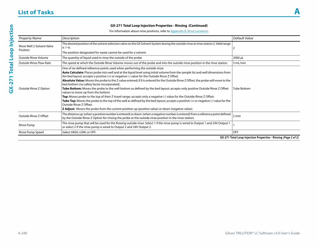
List of Tasks A
A-240 Gilson TRILUTION® LC Software v3.0 User’s Guide
GX-
271
Tota
l Loo
p In
ject
ion
Rinse Well 2 Solvent Valve Position
The desired position of the solvent selection valve on the GX Solvent System during the outside rinse at rinse station 2. Valid range is 1–6.
The position designated for waste cannot be used for a solvent.2
Outside Rinse Volume The quantity of liquid used to rinse the outside of the probe. 2000 μL
Outside Rinse Flow Rate The speed at which the Outside Rinse Volume moves out of the probe and into the outside rinse position in the rinse station. 5 mL/min
Outside Rinse Z Option
One of six defined reference points used when performing the outside rinse:Auto Calculate: Places probe into well and at the liquid level using initial volume from the sample list and well dimensions from the bed layout; accepts a positive (+) or negative (-) value for the Outside Rinse Z Offset.Absolute Value: Moves the probe to the Z-value entered; if 0 is entered for the Outside Rinse Z Offset, the probe will move to the bed bottom (no safety factor incorporated).Tube Bottom: Moves the probe to the well bottom as defined by the bed layout; accepts only positive Outside Rinse Z Offset values to move up from the bottom.Top: Moves probe to the top of their Z-travel range; accepts only a negative (-) value for the Outside Rinse Z Offset.Tube Top: Moves the probe to the top of the well as defined by the bed layout; accepts a positive (+) or negative (-) value for the Outside Rinse Z Offset.Z Adjust: Moves the probe from the current position up (positive value) or down (negative value).
Tube Bottom
Outside Rinse Z Offset The distance up (when a positive number is entered) or down (when a negative number is entered) from a reference point defined by the Outside Rinse Z Option for rinsing the probe at the outside rinse position in the rinse station. 2 mm
Rinse Pump The rinse pump that will be used for the flowing outside rinse. Select 1 if the rinse pump is wired to Output 1 and 24V Output 1 or select 2 if the rinse pump is wired to Output 2 and 24V Output 2. 1
Rinse Pump Speed Select HIGH, LOW, or OFF. OFF
GX-271 Total Loop Injection Properties - Rinsing (Continued)For information about rinse positions, refer to Appendix B, Rinse Locations.
Property Name Description Default Value
GX-271 Total Loop Injection Properties - Rinsing (Page 2 of 2)

Gilson TRILUTION® LC Software v3.0 User’s Guide A-241
List of Tasks AG
X-271 Total Loop Injection
GX-271 Total Loop Injection - Sequence of StepsThe following is an overview for the sequence of steps.
1 Initialize2 Aspirate3 Inject4 Injection Port Rinse5 Outside Rinse
Initialize1 Move Z to Z Safe Height.2 Set injection valve to INJECT.3 Move to Drain Well in Drain Zone.4 Lower probe into well to Drain Z Option and Drain Z Offset.5 Switch solvent valve to Solvent Valve Position and dispense volume held by transfer tubing at 5 mL/min.6 Move Z to Z Safe Height.
Aspirate1 Switch solvent valve to waste and aspirate Air Gap Volume at Air Gap Flow Rate.2 Move to Sample Well in Sample Zone.3 Lower probe into well to Sample Z Option and Sample Z Offset.4 Aspirate Loop Volume + Extra Volume at Aspirate Flow Rate.5 Move Z to Z Safe Height.
Inject1 Move to Injection Well in Injection Zone.2 Lower probe to Injection Z Option and Injection Z Offset.3 Switch injection valve to LOAD.4 Wait 1.2 sec.5 Switch solvent valve to Solvent Valve Position and dispense Loop Volume + 1/2 Extra Volume at Dispense Flow Rate.6 Wait Injection Equilibration Time.7 Synchronize.8 Switch injection valve to INJECT.

List of Tasks A
A-242 Gilson TRILUTION® LC Software v3.0 User’s Guide
GX-
271
Tota
l Loo
p In
ject
ion Injection Port Rinse
1 Switch solvent valve to Solvent Valve Position and dispense volume held by transfer tubing at 5 mL/min.2 Dispense Injection Rinse Volume at Injection Rinse Flow Rate.3 Move Z to Z Safe Height
Outside Rinse1 Move Z to Z Safe Height.2 Move to rinse station/well 1 in Outside Rinse Zone.3 Lower probe into well to Outside Rinse Z Option and Outside Rinse Z Offset.4 Switch Rinse Pump on at Rinse Pump Speed.5 Switch solvent valve to Rinse Well 1 Solvent Valve Position and dispense Outside Rinse Volume at Outside Rinse Flow Rate. If the current solvent valve position
is not the same as the previous solvent valve position, dispense Outside Rinse Volume + 2000 uL + Transfer Tubing volume.6 Switch Rinse Pump off.7 Move Z to Z Safe Height.8 Repeat steps 2–7 for the Number of Rinse Stations, incrementing the rinse station/well for each rinse station.
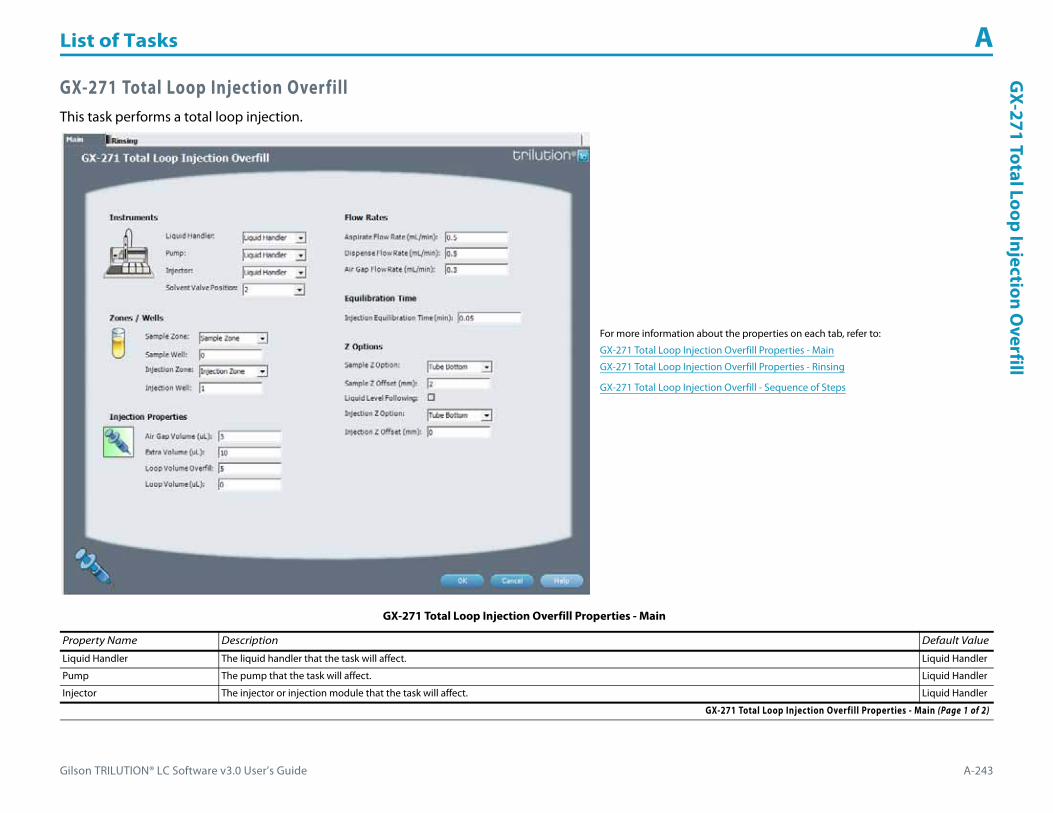
Gilson TRILUTION® LC Software v3.0 User’s Guide A-243
List of Tasks AG
X-271 Total Loop Injection Overfill
GX-271 Total Loop Injection OverfillThis task performs a total loop injection.
For more information about the properties on each tab, refer to:
GX-271 Total Loop Injection Overfill Properties - Main
GX-271 Total Loop Injection Overfill Properties - Rinsing
GX-271 Total Loop Injection Overfill - Sequence of Steps
GX-271 Total Loop Injection Overfill Properties - Main
Property Name Description Default Value
Liquid Handler The liquid handler that the task will affect. Liquid Handler
Pump The pump that the task will affect. Liquid Handler
Injector The injector or injection module that the task will affect. Liquid Handler
GX-271 Total Loop Injection Overfill Properties - Main (Page 1 of 2)

List of Tasks A
A-244 Gilson TRILUTION® LC Software v3.0 User’s Guide
GX-
271
Tota
l Loo
p In
ject
ion
Ove
rfill
Solvent Valve PositionThe desired position of the solvent selection valve on the GX Solvent System. Valid range is 1–6.
The position designated for waste cannot be used for a solvent.2
Sample Zone The zone from which the Injection Volume and Extra Volume are aspirated. Sample Zone
Sample Well Enter the well number in the Sample Zone. 0
Injection Zone The zone to which the Extra Volume and Loop Volume are dispensed. Injection Zone
Injection Well Enter the well number in the Injection Zone. 1
Air Gap Volume The quantity of an air gap. 3 μL
Extra Volume An additional volume to the first volume aspirated. It ensures that the actual volume of liquid to be transferred is not contaminated, and acts as an extra buffer between the air gap/reservoir solvent and the Injection Volume. 10 μL
Loop Volume Overfill A factor to multiply the Loop Volume by that determines the injection volume. Injection Volume = Loop Volume Overfill x Loop Volume. 5
Loop Volume The capacity of the installed sample loop. 0 μL
Aspirate Flow Rate The speed at which liquid volumes move into the probe. 0.5 mL/min
Dispense Flow Rate The speed at which liquid volumes move out of the probe. 0.5 mL/min
Air Gap Flow Rate The speed at which the Air Gap Volume moves into the probe. 0.3 mL/min
Injection Equilibration Time The time the program waits after loading the Extra Volume, Injection Volume, and Push Volume in the sample loop. 0.05 min
Sample Z Option
One of six defined reference points used when aspirating the Injection Volume and Extra Volume from the bed:Auto Calculate: Places probe into well and at the liquid level using initial volume from the sample list and well dimensions from the bed layout; accepts a positive (+) or negative (-) value for the Sample Z Offset.Absolute Value: Moves the probe to the Z-value entered; if 0 is entered, probe will move to the bed bottom (no safety factor incorporated).Tube Bottom: Moves the probe to the well bottom as defined by the bed layout; accepts only positive Sample Z Offset value to move up from the bottom.Top: Moves probe to the top of their Z-travel range; accepts only a negative (-) value for the Sample Z Offset.Tube Top: Moves the probe to the top of the well as defined by the bed layout; accepts a positive (+) or negative (-) value for the Sample Z Offset.Z Adjust: Moves the probe from the current position up (positive value) or down (negative value).
Tube Bottom
Sample Z Offset The distance up (when a positive number is entered) or down (when a negative number is entered) from a reference point defined by the Sample Z Option used when aspirating the Injection Volume and Extra Volume from the bed. 2 mm
Liquid Level FollowingWhen selected, the probe will follow the liquid down as it is aspirated from the Sample Zone. The Sample Z Option must be set to AUTO CALCULATE and initial volumes must be set in the sample list to use this option.
When cleared, the probe will not follow the liquid down as it is aspirated from the Sample Zone.Cleared
Injection Z Option
One of six defined reference points used when performing the injection:Auto Calculate: Places probe into well and at the liquid level using initial volume from the sample list and well dimensions from the bed layout; accepts a positive (+) or negative (-) value for the Injection Z Offset.Absolute Value: Moves the probe to the Z-value entered; if 0 is entered for the Injection Z Offset, probe will move to the bed bottom (no safety factor incorporated).Tube Bottom: Moves the probe to the well bottom as defined by the bed layout; accepts only positive Injection Z Offset values to move up from the bottom.Top: Moves probe to the top of their Z-travel range; accepts only a negative (-) value for the Injection Z Offset.Tube Top: Moves the probe to the top of the well as defined by the bed layout; accepts a positive (+) or negative (-) value for the Injection Z Offset.Z Adjust: Moves the probe from the current position up (positive value) or down (negative value).
Tube Bottom
Injection Z Offset The distance up (when a positive number is entered) or down (when a negative number is entered) from a reference point defined by the Injection Z Option when performing the injection. 0
GX-271 Total Loop Injection Overfill Properties - Main (Continued)
Property Name Description Default Value
GX-271 Total Loop Injection Overfill Properties - Main (Page 2 of 2)

Gilson TRILUTION® LC Software v3.0 User’s Guide A-245
List of Tasks AG
X-271 Total Loop Injection Overfill
GX-271 Total Loop Injection Overfill Properties - Rinsing For information about rinse positions, refer to Appendix B, Rinse Locations.
Property Name Description Default Value
Drain Zone The zone in which the dilutor is homed. Inside Rinse
Drain Well Enter the well number in the Drain Zone. 1
Drain Z Option
One of six defined reference points used when purging to the drain:Auto Calculate: Places probe into well and at the liquid level using initial volume from the sample list and well dimensions from the bed layout; accepts a positive (+) or negative (-) value for the Drain Z Offset.Absolute Value: Moves the probe to the Z-value entered; if 0 is entered for the Drain Z Offset, probe will move to the bed bottom (no safety factor incorporated).Tube Bottom: Moves the probe to the well bottom as defined by the bed layout; accepts only positive Drain Z Offset values to move up from the bottom.Top: Moves probe to the top of their Z-travel range; accepts only a negative (-) value for the Drain Z Offset.Tube Top: Moves the probe to the top of the well as defined by the bed layout; accepts a positive (+) or negative (-) value for the Drain Z Offset.Z Adjust: Moves the probe from the current position up (positive value) or down (negative value).
Tube Top
Drain Z Offset The distance up (when a positive number is entered) or down (when a negative number is entered) from a reference point defined by the Drain Z Option for purging to the drain. -7
Injection Rinse Volume The quantity of liquid used to rinse the injection port at Injection Well in Injection Zone. 500 μL
Injection Rinse Flow Rate The speed at which the Injection Rinse Volume moves out of the probe and into the injection port. 4 mL/min
Outside Rinse Zone The zone to which the Outside Rinse Volume is delivered. Outside Rinse
Number of Rinse Stations Select the number of rinse stations to be used when performing the outside rinse. Valid range is 1–2. 1
Rinse Well 1 Solvent Valve PositionThe desired position of the solvent selection valve on the GX Solvent System during the outside rinse at rinse station 1. Valid range is 1–6.
The position designated for waste cannot be used for a solvent.2
Rinse Well 2 Solvent Valve PositionThe desired position of the solvent selection valve on the GX Solvent System during the outside rinse at rinse station 2. Valid range is 1–6.
The position designated for waste cannot be used for a solvent.2
Outside Rinse Volume The quantity of liquid used to rinse the outside of the probe. 500 μL
Outside Rinse Flow Rate The speed at which the Outside Rinse Volume moves out of the probe and into the outside rinse position in the rinse station. 5 mL/min
Outside Rinse Z Option
One of six defined reference points used when performing the outside rinse:Auto Calculate: Places probe into well and at the liquid level using initial volume from the sample list and well dimensions from the bed layout; accepts a positive (+) or negative (-) value for the Outside Rinse Z Offset.Absolute Value: Moves the probe to the Z-value entered; if 0 is entered for the Outside Rinse Z Offset, the probe will move to the bed bottom (no safety factor incorporated).Tube Bottom: Moves the probe to the well bottom as defined by the bed layout; accepts only positive Outside Rinse Z Offset values to move up from the bottom.Top: Moves probe to the top of their Z-travel range; accepts only a negative (-) value for the Outside Rinse Z Offset.Tube Top: Moves the probe to the top of the well as defined by the bed layout; accepts a positive (+) or negative (-) value for the Outside Rinse Z Offset.Z Adjust: Moves the probe from the current position up (positive value) or down (negative value).
Tube Bottom
Outside Rinse Z Offset The distance up (when a positive number is entered) or down (when a negative number is entered) from a reference point defined by the Outside Rinse Z Option for rinsing the probe at the outside rinse position in the rinse station. 2 mm
Rinse Pump The rinse pump that will be used for the flowing outside rinse. Select 1 if the rinse pump is wired to Output 1 and 24V Output 1 or select 2 if the rinse pump is wired to Output 2 and 24V Output 2. 1
Rinse Pump Speed Select HIGH, LOW, or OFF. OFF
GX-271 Total Loop Injection Overfill Properties - Rinsing

List of Tasks A
A-246 Gilson TRILUTION® LC Software v3.0 User’s Guide
GX-
271
Tota
l Loo
p In
ject
ion
Ove
rfill GX-271 Total Loop Injection Overfill - Sequence of Steps
The following is an overview for the sequence of steps.
1 Initialize2 Aspirate3 Inject4 Injection Port Rinse5 Outside Rinse
Initialize1 Move Z to Z Safe Height.2 Set injection valve to INJECT.3 Move to Drain Well in Drain Zone.4 Lower probe into well to Drain Z Option and Drain Z Offset.5 Switch solvent valve to Solvent Valve Position and dispense volume held by transfer tubing at 5 mL/min.6 Move Z to Z Safe Height.
Aspirate1 Switch solvent valve to waste and aspirate Air Gap Volume at Air Gap Flow Rate.2 Move to Sample Well in Sample Zone.3 Lower probe into well to Sample Z Option and Sample Z Offset.4 Aspirate the injection volume (injection volume = Loop Overfill x Loop Volume) + Extra Volume at Aspirate Flow Rate.5 Move Z to Z Safe Height.
Inject1 Move to Injection Well in Injection Zone.2 Lower probe to Injection Z Option and Injection Z Offset.3 Switch injection valve to LOAD.4 Wait 1.2 sec.5 Switch solvent valve to Solvent Valve Position and dispense injection volume (injection volume = Loop Overfill x Loop Volume) at Dispense Flow Rate.6 Wait Injection Equilibration Time.7 Synchronize.8 Switch injection valve to INJECT.

Gilson TRILUTION® LC Software v3.0 User’s Guide A-247
List of Tasks AG
X-271 Total Loop Injection Overfill
Injection Port Rinse1 Switch solvent valve to Solvent Valve Position and dispense volume held by transfer tubing at 5 mL/min.2 Dispense Injection Rinse Volume at Injection Rinse Flow Rate.3 Move Z to Z Safe Height
Outside Rinse1 Move Z to Z Safe Height.2 Move to rinse station/well 1 in Outside Rinse Zone.3 Lower probe into well to Outside Rinse Z Option and Outside Rinse Z Offset.4 Switch Rinse Pump on at Rinse Pump Speed.5 Switch solvent valve to Rinse Well 1 Solvent Valve Position and dispense Outside Rinse Volume at Outside Rinse Flow Rate. If the current solvent valve position
is not the same as the previous solvent valve position, dispense Outside Rinse Volume + 2000 uL + Transfer Tubing volume.6 Switch Rinse Pump off.7 Move Z to Z Safe Height.8 Repeat steps 2–7 for the Number of Rinse Stations, incrementing the rinse station/well for each rinse station.

List of Tasks A
A-248 Gilson TRILUTION® LC Software v3.0 User’s Guide
GX-
281
Low
Vol
ume
Part
ial L
oop
Inje
ctio
n GX-281 Low Volume Partial Loop InjectionThis task performs a partial loop injection using a push volume from the reservoir to push the injection volume into the sample loop.
For more information about the properties on each tab, refer to:
GX-281 Low Volume Partial Loop Injection Properties - Main
GX-281 Low Volume Partial Loop Injection Properties - Rinsing
GX-281 Low Volume Partial Loop Injection - Sequence of Steps
GX-281 Low Volume Partial Loop Injection Properties - Main
Property Name Description Default Value
Liquid Handler The liquid handler that the task will affect. Liquid Handler
Pump The pump that the task will affect. Liquid Handler
Injector The injector or injection module that the task will affect. Liquid Handler
GX-281 Low Volume Partial Loop Injection Properties - Main (Page 1 of 3)

Gilson TRILUTION® LC Software v3.0 User’s Guide A-249
List of Tasks AG
X-281 Low Volum
e Partial Loop Injection
Solvent Valve PositionThe desired position of the solvent selection valve on the GX Solvent System. Valid range is 1–6.
The position designated for waste cannot be used for a solvent.2
Valve IDEnter 2 for the Left GX Direct Injection Module.
Enter 3 for the Right GX Direct Injection Module.3
Sample Zone The zone from which the Injection Volume and Extra Volume are aspirated. Sample Zone
Sample Well Enter the well number in the Sample Zone. 0
Injection Zone The zone to which the Extra Volume, Injection Volume, and Push Volume are dispensed. Injection Zone
Injection Well Enter the well number in the Injection Zone. 1
Air Gap Volume The quantity of an air gap. 50 μL
Extra Volume An additional volume to the first volume aspirated. It ensures that the actual volume of liquid to be transferred is not contaminated, and acts as an extra buffer between the air gap/reservoir solvent and the Injection Volume. 25 μL
Push Volume A volume of reservoir solvent used to push the injection volume into the sample loop. 20 μL
Injection Volume The volume of sample to be injected. 0 μL
Aspirate Flow Rate The speed at which liquid volumes move into the probe. 5 mL/min
Dispense Flow Rate The speed at which liquid volumes move out of the probe. 5 mL/min
Air Gap Flow Rate The speed at which the Air Gap Volume moves into the probe. 1 mL/min
Injection Equilibration Time The time the program waits after loading the Extra Volume, Injection Volume, and Push Volume in the sample loop. 0.05 min
Sample Z Option
One of six defined reference points used when aspirating the Injection Volume and Extra Volume from the bed:Auto Calculate: Places probe into well and at the liquid level using initial volume from the sample list and well dimensions from the bed layout; accepts a positive (+) or negative (-) value for the Sample Z Offset.Absolute Value: Moves the probe to the Z-value entered; if 0 is entered, probe will move to the bed bottom (no safety factor incorporated).Tube Bottom: Moves the probe to the well bottom as defined by the bed layout; accepts only positive Sample Z Offset value to move up from the bottom.Top: Moves probe to the top of their Z-travel range; accepts only a negative (-) value for the Sample Z Offset.Tube Top: Moves the probe to the top of the well as defined by the bed layout; accepts a positive (+) or negative (-) value for the Sample Z Offset.Z Adjust: Moves the probe from the current position up (positive value) or down (negative value).
Tube Bottom
Sample Z Offset The distance up (when a positive number is entered) or down (when a negative number is entered) from a reference point defined by the Sample Z Option used when aspirating the Injection Volume and Extra Volume from the bed. 2 mm
Liquid Level FollowingWhen selected, the probe will follow the liquid down as it is aspirated from the Sample Zone. The Sample Z Option must be set to AUTO CALCULATE and initial volumes must be set in the sample list to use this option.
When cleared, the probe will not follow the liquid down as it is aspirated from the Sample Zone.Cleared
GX-281 Low Volume Partial Loop Injection Properties - Main (Continued)
Property Name Description Default Value
GX-281 Low Volume Partial Loop Injection Properties - Main (Page 2 of 3)

List of Tasks A
A-250 Gilson TRILUTION® LC Software v3.0 User’s Guide
GX-
281
Low
Vol
ume
Part
ial L
oop
Inje
ctio
n
Injection Z Option
One of six defined reference points used when performing the injection:Auto Calculate: Places probe into well and at the liquid level using initial volume from the sample list and well dimensions from the bed layout; accepts a positive (+) or negative (-) value for the Injection Z Offset.Absolute Value: Moves the probe to the Z-value entered; if 0 is entered for the Injection Z Offset, probe will move to the bed bottom (no safety factor incorporated).Tube Bottom: Moves the probe to the well bottom as defined by the bed layout; accepts only positive Injection Z Offset values to move up from the bottom.Top: Moves probe to the top of their Z-travel range; accepts only a negative (-) value for the Injection Z Offset.Tube Top: Moves the probe to the top of the well as defined by the bed layout; accepts a positive (+) or negative (-) value for the Injection Z Offset.Z Adjust: Moves the probe from the current position up (positive value) or down (negative value).
Tube Bottom
Injection Z Offset The distance up (when a positive number is entered) or down (when a negative number is entered) from a reference point defined by the Injection Z Option when performing the injection. 0
GX-281 Low Volume Partial Loop Injection Properties - Rinsing For information about rinse positions, refer to Appendix B, Rinse Locations.
Property Name Description Default Value
Drain Zone The zone in which the GX Solvent System is homed. Inside Rinse
Drain Well Enter the well number in the Drain Zone. 1
Drain Z Option
One of six defined reference points used when purging to the drain:Auto Calculate: Places probe into well and at the liquid level using initial volume from the sample list and well dimensions from the bed layout; accepts a positive (+) or negative (-) value for the Drain Z Offset.Absolute Value: Moves the probe to the Z-value entered; if 0 is entered for the Drain Z Offset, probe will move to the bed bottom (no safety factor incorporated).Tube Bottom: Moves the probe to the well bottom as defined by the bed layout; accepts only positive Drain Z Offset values to move up from the bottom.Top: Moves probe to the top of their Z-travel range; accepts only a negative (-) value for the Drain Z Offset.Tube Top: Moves the probe to the top of the well as defined by the bed layout; accepts a positive (+) or negative (-) value for the Drain Z Offset.Z Adjust: Moves the probe from the current position up (positive value) or down (negative value).
Tube Top
Drain Z Offset The distance up (when a positive number is entered) or down (when a negative number is entered) from a reference point defined by the Drain Z Option for purging to the drain. -7
Injection Rinse Volume The quantity of liquid used to rinse the injection port at Injection Well in Injection Zone. 1000 μL
Injection Rinse Flow Rate The speed at which the Injection Rinse Volume moves out of the probe and into the injection port. 5 mL/min
Outside Rinse Zone The zone to which the Outside Rinse Volume is delivered. Outside Rinse
Number of Rinse Stations Select the number of rinse stations to be used when performing the outside rinse. Valid range is 1–5. 1
Rinse Well 1 Solvent Valve PositionThe desired position of the solvent selection valve on the GX Solvent System during the outside rinse at rinse station 1. Valid range is 1–6.
The position designated for waste cannot be used for a solvent.2
Rinse Well 2 Solvent Valve PositionThe desired position of the solvent selection valve on the GX Solvent System during the outside rinse at rinse station 2. Valid range is 1–6.
The position designated for waste cannot be used for a solvent.2
Outside Rinse Volume The quantity of liquid used to rinse the outside of the probe. 2000 μL
Outside Rinse Flow Rate The speed at which the Outside Rinse Volume moves out of the probe and into the outside rinse position in the rinse station. 5 mL/min
GX-281 Low Volume Partial Loop Injection Properties - Rinsing (Page 1 of 2)
GX-281 Low Volume Partial Loop Injection Properties - Main (Continued)
Property Name Description Default Value
GX-281 Low Volume Partial Loop Injection Properties - Main (Page 3 of 3)

Gilson TRILUTION® LC Software v3.0 User’s Guide A-251
List of Tasks AG
X-281 Low Volum
e Partial Loop Injection
GX-281 Low Volume Partial Loop Injection - Sequence of StepsThe following is an overview for the sequence of steps.
1 Initialize2 Aspirate3 Inject4 Injection Port Rinse5 Outside Rinse
Initialize1 Move Z to Z Safe Height.2 Set injection valve to INJECT.3 Move to Drain Well in Drain Zone.4 Lower probe into well to Drain Z Option and Drain Z Offset.5 Switch solvent valve to Solvent Valve Position and dispense volume held by transfer tubing at 5 mL/min.6 Move Z to Z Safe Height.
Outside Rinse Z Option
One of six defined reference points used when performing the outside rinse:Auto Calculate: Places probe into well and at the liquid level using initial volume from the sample list and well dimensions from the bed layout; accepts a positive (+) or negative (-) value for the Outside Rinse Z Offset.Absolute Value: Moves the probe to the Z-value entered; if 0 is entered for the Outside Rinse Z Offset, the probe will move to the bed bottom (no safety factor incorporated).Tube Bottom: Moves the probe to the well bottom as defined by the bed layout; accepts only positive Outside Rinse Z Offset values to move up from the bottom.Top: Moves probe to the top of their Z-travel range; accepts only a negative (-) value for the Outside Rinse Z Offset.Tube Top: Moves the probe to the top of the well as defined by the bed layout; accepts a positive (+) or negative (-) value for the Outside Rinse Z Offset.Z Adjust: Moves the probe from the current position up (positive value) or down (negative value).
Tube Bottom
Outside Rinse Z Offset The distance up (when a positive number is entered) or down (when a negative number is entered) from a reference point defined by the Outside Rinse Z Option for rinsing the probe at the outside rinse position in the rinse station. 2 mm
Rinse Pump The rinse pump that will be used for the flowing outside rinse. Select 1 if the rinse pump is wired to Output 1 and 24V Output 1 or select 2 if the rinse pump is wired to Output 2 and 24V Output 2. 1
Rinse Pump Speed Select HIGH, LOW, or OFF. OFF
GX-281 Low Volume Partial Loop Injection Properties - Rinsing (Continued)For information about rinse positions, refer to Appendix B, Rinse Locations.
Property Name Description Default Value
GX-281 Low Volume Partial Loop Injection Properties - Rinsing (Page 2 of 2)
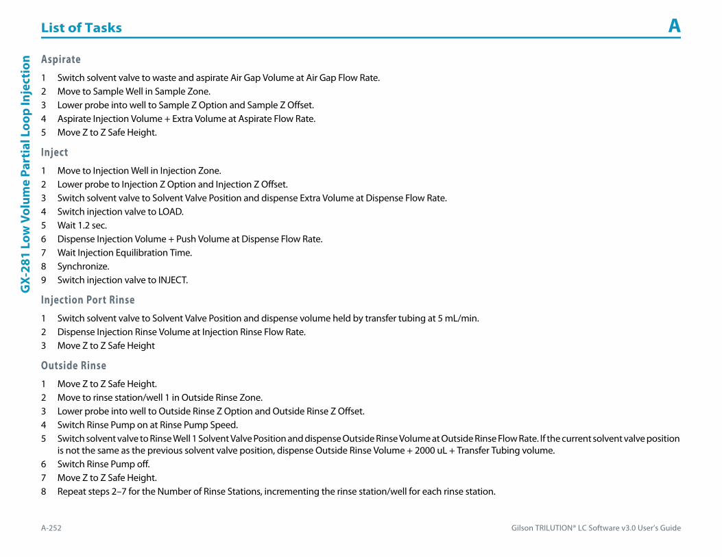
List of Tasks A
A-252 Gilson TRILUTION® LC Software v3.0 User’s Guide
GX-
281
Low
Vol
ume
Part
ial L
oop
Inje
ctio
n Aspirate1 Switch solvent valve to waste and aspirate Air Gap Volume at Air Gap Flow Rate.2 Move to Sample Well in Sample Zone.3 Lower probe into well to Sample Z Option and Sample Z Offset.4 Aspirate Injection Volume + Extra Volume at Aspirate Flow Rate.5 Move Z to Z Safe Height.
Inject1 Move to Injection Well in Injection Zone.2 Lower probe to Injection Z Option and Injection Z Offset.3 Switch solvent valve to Solvent Valve Position and dispense Extra Volume at Dispense Flow Rate.4 Switch injection valve to LOAD.5 Wait 1.2 sec.6 Dispense Injection Volume + Push Volume at Dispense Flow Rate.7 Wait Injection Equilibration Time.8 Synchronize.9 Switch injection valve to INJECT.
Injection Port Rinse1 Switch solvent valve to Solvent Valve Position and dispense volume held by transfer tubing at 5 mL/min.2 Dispense Injection Rinse Volume at Injection Rinse Flow Rate.3 Move Z to Z Safe Height
Outside Rinse1 Move Z to Z Safe Height.2 Move to rinse station/well 1 in Outside Rinse Zone.3 Lower probe into well to Outside Rinse Z Option and Outside Rinse Z Offset.4 Switch Rinse Pump on at Rinse Pump Speed.5 Switch solvent valve to Rinse Well 1 Solvent Valve Position and dispense Outside Rinse Volume at Outside Rinse Flow Rate. If the current solvent valve position
is not the same as the previous solvent valve position, dispense Outside Rinse Volume + 2000 uL + Transfer Tubing volume.6 Switch Rinse Pump off.7 Move Z to Z Safe Height.8 Repeat steps 2–7 for the Number of Rinse Stations, incrementing the rinse station/well for each rinse station.

Gilson TRILUTION® LC Software v3.0 User’s Guide A-253
List of Tasks AG
X-281 Partial Loop Injection
GX-281 Partial Loop InjectionThis task performs a partial loop injection.
For more information about the properties on each tab, refer to:
GX-281 Partial Loop Injection Properties - Main
GX-281 Partial Loop Injection Properties - Rinsing
GX-281 Partial Loop Injection - Sequence of Steps
GX-281 Partial Loop Injection Properties - Main
Property Name Description Default Value
Liquid Handler The liquid handler that the task will affect. Liquid Handler
Pump The pump that the task will affect. Liquid Handler
Injector The injector or injection module that the task will affect. Liquid Handler
GX-281 Partial Loop Injection Properties - Main (Page 1 of 3)

List of Tasks A
A-254 Gilson TRILUTION® LC Software v3.0 User’s Guide
GX-
281
Part
ial L
oop
Inje
ctio
n
Solvent Valve PositionThe desired position of the solvent selection valve on the GX Solvent System. Valid range is 1–6.
The position designated for waste cannot be used for a solvent.2
Valve IDEnter 2 for the Left GX Direct Injection Module.
Enter 3 for the Right GX Direct Injection Module.3
Sample Zone The zone from which the Injection Volume and Extra Volume are aspirated. Sample Zone
Sample Well Enter the well number in the Sample Zone. 0
Injection Zone The zone to which the Extra Volume and Injection Volume are dispensed. Injection Zone
Injection Well Enter the well number in the Injection Zone. 1
Air Gap Volume The quantity of an air gap. 50 μL
Extra Volume An additional volume to the first volume aspirated. It ensures that the actual volume of liquid to be transferred is not contaminated, and acts as an extra buffer between the air gap/reservoir solvent and the Injection Volume. 20 μL
Injection Volume The volume of sample to be injected. 0 μL
Aspirate Flow Rate The speed at which liquid volumes move into the probe. 5 mL/min
Dispense Flow Rate The speed at which liquid volumes move out of the probe. 5 mL/min
Air Gap Flow Rate The speed at which the Air Gap Volume moves into the probe. 1 mL/min
Injection Equilibration Time The time the program waits after loading the Extra Volume and Injection Volume in the sample loop. 0.05 min
Sample Z Option
One of six defined reference points used when aspirating the Injection Volume and Extra Volume from the bed:Auto Calculate: Places probe into well and at the liquid level using initial volume from the sample list and well dimensions from the bed layout; accepts a positive (+) or negative (-) value for the Sample Z Offset.Absolute Value: Moves the probe to the Z-value entered; if 0 is entered, probe will move to the bed bottom (no safety factor incorporated).Tube Bottom: Moves the probe to the well bottom as defined by the bed layout; accepts only positive Sample Z Offset value to move up from the bottom.Top: Moves probe to the top of their Z-travel range; accepts only a negative (-) value for the Sample Z Offset.Tube Top: Moves the probe to the top of the well as defined by the bed layout; accepts a positive (+) or negative (-) value for the Sample Z Offset.Z Adjust: Moves the probe from the current position up (positive value) or down (negative value).
Tube Bottom
Sample Z Offset The distance up (when a positive number is entered) or down (when a negative number is entered) from a reference point defined by the Sample Z Option used when aspirating the Injection Volume and Extra Volume from the bed. 2 mm
Liquid Level FollowingWhen selected, the probe will follow the liquid down as it is aspirated from the Sample Zone. The Sample Z Option must be set to AUTO CALCULATE and initial volumes must be set in the sample list to use this option.
When cleared, the probe will not follow the liquid down as it is aspirated from the Sample Zone.Cleared
GX-281 Partial Loop Injection Properties - Main (Continued)
Property Name Description Default Value
GX-281 Partial Loop Injection Properties - Main (Page 2 of 3)

Gilson TRILUTION® LC Software v3.0 User’s Guide A-255
List of Tasks AG
X-281 Partial Loop Injection
Injection Z Option
One of six defined reference points used when performing the injection:Auto Calculate: Places probe into well and at the liquid level using initial volume from the sample list and well dimensions from the bed layout; accepts a positive (+) or negative (-) value for the Injection Z Offset.Absolute Value: Moves the probe to the Z-value entered; if 0 is entered for the Injection Z Offset, probe will move to the bed bottom (no safety factor incorporated).Tube Bottom: Moves the probe to the well bottom as defined by the bed layout; accepts only positive Injection Z Offset values to move up from the bottom.Top: Moves probe to the top of their Z-travel range; accepts only a negative (-) value for the Injection Z Offset.Tube Top: Moves the probe to the top of the well as defined by the bed layout; accepts a positive (+) or negative (-) value for the Injection Z Offset.Z Adjust: Moves the probe from the current position up (positive value) or down (negative value).
Tube Bottom
Injection Z Offset The distance up (when a positive number is entered) or down (when a negative number is entered) from a reference point defined by the Injection Z Option when performing the injection. 0
GX-281 Partial Loop Injection Properties - Rinsing For information about rinse positions, refer to Appendix B, Rinse Locations.
Property Name Description Default Value
Drain Zone The zone in which the GX Solvent System is homed. Inside Rinse
Drain Well Enter the well number in the Drain Zone. 1
Drain Z Option
One of six defined reference points used when purging to the drain:Auto Calculate: Places probe into well and at the liquid level using initial volume from the sample list and well dimensions from the bed layout; accepts a positive (+) or negative (-) value for the Drain Z Offset.Absolute Value: Moves the probe to the Z-value entered; if 0 is entered for the Drain Z Offset, probe will move to the bed bottom (no safety factor incorporated).Tube Bottom: Moves the probe to the well bottom as defined by the bed layout; accepts only positive Drain Z Offset values to move up from the bottom.Top: Moves probe to the top of their Z-travel range; accepts only a negative (-) value for the Drain Z Offset.Tube Top: Moves the probe to the top of the well as defined by the bed layout; accepts a positive (+) or negative (-) value for the Drain Z Offset.Z Adjust: Moves the probe from the current position up (positive value) or down (negative value).
Tube Top
Drain Z Offset The distance up (when a positive number is entered) or down (when a negative number is entered) from a reference point defined by the Drain Z Option for purging to the drain. -7
Injection Rinse Volume The quantity of liquid used to rinse the injection port at Injection Well in Injection Zone. 1000 μL
Injection Rinse Flow Rate The speed at which the Injection Rinse Volume moves out of the probe and into the injection port. 5 mL/min
Outside Rinse Zone The zone to which the Outside Rinse Volume is delivered. Outside Rinse
Number of Rinse Stations Select the number of rinse stations to be used when performing the outside rinse. Valid range is 1–5. 1
Rinse Well 1 Solvent Valve PositionThe desired position of the solvent selection valve on the GX Solvent System during the outside rinse at rinse station 1. Valid range is 1–6.
The position designated for waste cannot be used for a solvent.2
Rinse Well 2 Solvent Valve PositionThe desired position of the solvent selection valve on the GX Solvent System during the outside rinse at rinse station 2. Valid range is 1–6.
The position designated for waste cannot be used for a solvent.2
Rinse Well 3 Solvent Valve PositionThe desired position of the solvent selection valve on the GX Solvent System during the outside rinse at rinse station 3. Valid range is 1–6.
The position designated for waste cannot be used for a solvent.2
GX-281 Partial Loop Injection Properties - Rinsing (Page 1 of 2)
GX-281 Partial Loop Injection Properties - Main (Continued)
Property Name Description Default Value
GX-281 Partial Loop Injection Properties - Main (Page 3 of 3)
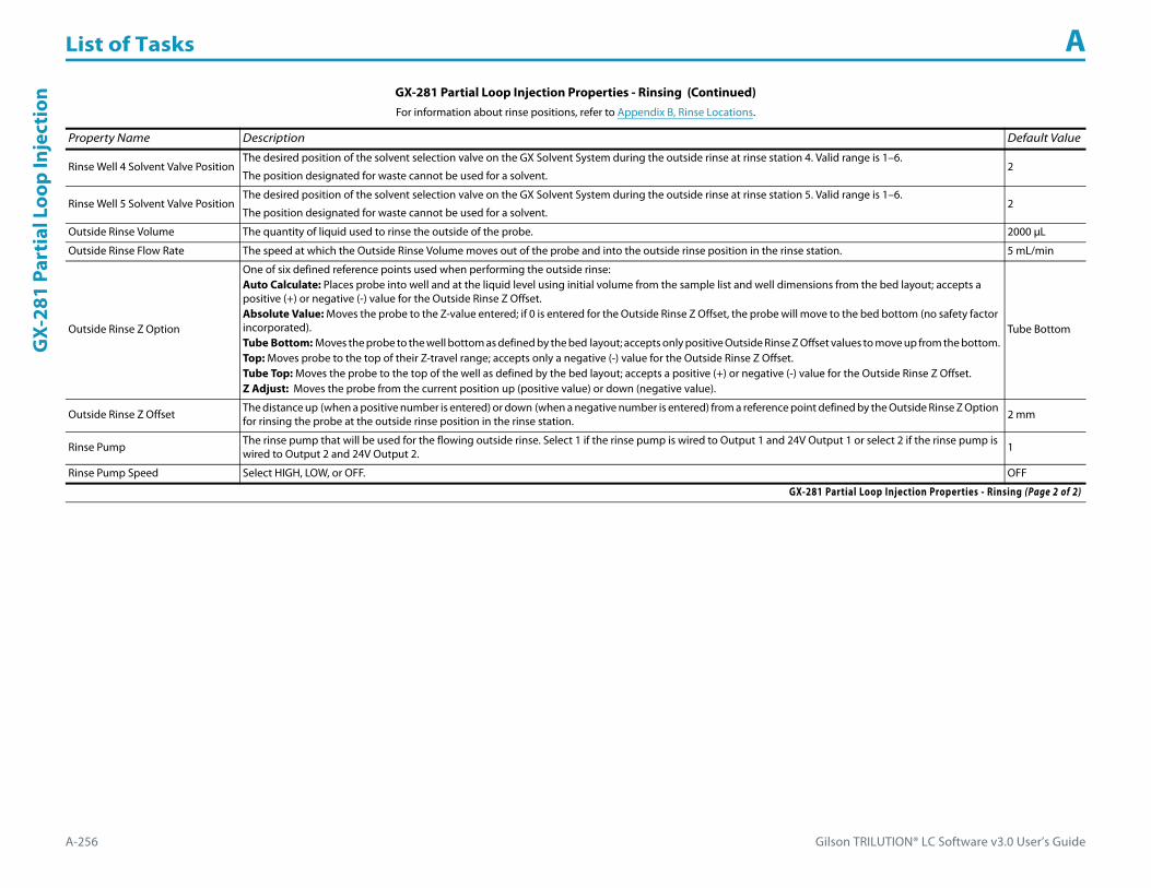
List of Tasks A
A-256 Gilson TRILUTION® LC Software v3.0 User’s Guide
GX-
281
Part
ial L
oop
Inje
ctio
n
Rinse Well 4 Solvent Valve PositionThe desired position of the solvent selection valve on the GX Solvent System during the outside rinse at rinse station 4. Valid range is 1–6.
The position designated for waste cannot be used for a solvent.2
Rinse Well 5 Solvent Valve PositionThe desired position of the solvent selection valve on the GX Solvent System during the outside rinse at rinse station 5. Valid range is 1–6.
The position designated for waste cannot be used for a solvent.2
Outside Rinse Volume The quantity of liquid used to rinse the outside of the probe. 2000 μL
Outside Rinse Flow Rate The speed at which the Outside Rinse Volume moves out of the probe and into the outside rinse position in the rinse station. 5 mL/min
Outside Rinse Z Option
One of six defined reference points used when performing the outside rinse:Auto Calculate: Places probe into well and at the liquid level using initial volume from the sample list and well dimensions from the bed layout; accepts a positive (+) or negative (-) value for the Outside Rinse Z Offset.Absolute Value: Moves the probe to the Z-value entered; if 0 is entered for the Outside Rinse Z Offset, the probe will move to the bed bottom (no safety factor incorporated).Tube Bottom: Moves the probe to the well bottom as defined by the bed layout; accepts only positive Outside Rinse Z Offset values to move up from the bottom.Top: Moves probe to the top of their Z-travel range; accepts only a negative (-) value for the Outside Rinse Z Offset.Tube Top: Moves the probe to the top of the well as defined by the bed layout; accepts a positive (+) or negative (-) value for the Outside Rinse Z Offset.Z Adjust: Moves the probe from the current position up (positive value) or down (negative value).
Tube Bottom
Outside Rinse Z Offset The distance up (when a positive number is entered) or down (when a negative number is entered) from a reference point defined by the Outside Rinse Z Option for rinsing the probe at the outside rinse position in the rinse station. 2 mm
Rinse Pump The rinse pump that will be used for the flowing outside rinse. Select 1 if the rinse pump is wired to Output 1 and 24V Output 1 or select 2 if the rinse pump is wired to Output 2 and 24V Output 2. 1
Rinse Pump Speed Select HIGH, LOW, or OFF. OFF
GX-281 Partial Loop Injection Properties - Rinsing (Continued)For information about rinse positions, refer to Appendix B, Rinse Locations.
Property Name Description Default Value
GX-281 Partial Loop Injection Properties - Rinsing (Page 2 of 2)

Gilson TRILUTION® LC Software v3.0 User’s Guide A-257
List of Tasks AG
X-281 Partial Loop Injection
GX-281 Partial Loop Injection - Sequence of StepsThe following is an overview for the sequence of steps.
1 Initialize2 Aspirate3 Inject4 Injection Port Rinse5 Outside Rinse
Initialize1 Move Z to Z Safe Height.2 Set injection valve to INJECT.3 Move to Drain Well in Drain Zone.4 Lower probe into well to Drain Z Option and Drain Z Offset.5 Switch solvent valve to Solvent Valve Position and dispense volume held by transfer tubing at 5 mL/min.6 Move Z to Z Safe Height.
Aspirate1 Switch solvent valve to waste and aspirate Air Gap Volume at Air Gap Flow Rate.2 Move to Sample Well in Sample Zone.3 Lower probe into well to Sample Z Option and Sample Z Offset.4 Aspirate Injection Volume + Extra Volume at Aspirate Flow Rate.5 Move Z to Z Safe Height.
Inject1 Move to Injection Well in Injection Zone.2 Lower probe to Injection Z Option and Injection Z Offset.3 Switch solvent valve to Solvent Valve Position and dispense Extra Volume at Dispense Flow Rate.4 Switch injection valve to LOAD.5 Wait 1.2 sec.6 Dispense Injection Volume at Dispense Flow Rate.7 Wait Injection Equilibration Time.8 Synchronize.9 Switch injection valve to INJECT.

List of Tasks A
A-258 Gilson TRILUTION® LC Software v3.0 User’s Guide
GX-
281
Part
ial L
oop
Inje
ctio
n Injection Port Rinse1 Switch solvent valve to Solvent Valve Position and dispense volume held by transfer tubing at 5 mL/min.2 Dispense Injection Rinse Volume at Injection Rinse Flow Rate.3 Move Z to Z Safe Height
Outside Rinse1 Move Z to Z Safe Height.2 Move to rinse station/well 1 in Outside Rinse Zone.3 Lower probe into well to Outside Rinse Z Option and Outside Rinse Z Offset.4 Switch Rinse Pump on at Rinse Pump Speed.5 Switch solvent valve to Rinse Well 1 Solvent Valve Position and dispense Outside Rinse Volume at Outside Rinse Flow Rate. If the current solvent valve position
is not the same as the previous solvent valve position, dispense Outside Rinse Volume + 2000 uL + Transfer Tubing volume.6 Switch Rinse Pump off.7 Move Z to Z Safe Height.8 Repeat steps 2–7 for the Number of Rinse Stations, incrementing the rinse station/well for each rinse station.

Gilson TRILUTION® LC Software v3.0 User’s Guide A-259
List of Tasks AG
X-281 Prep Injection with Collection
GX-281 Prep Injection with CollectionThis task performs a partial loop injection using a push volume from the reservoir to push the injection volume into the sample loop and includes a rinse of the fraction collection valve.
For more information about the properties on each tab, refer to:
GX-281 Prep Injection with Collection Properties - Main
GX-281 Prep Injection with Collection Properties - Rinsing
GX-281 Prep Injection with Collection - Sequence of Steps
GX-281 Prep Injection with Collection Properties - Main
Property Name Description Default Value
Liquid Handler The liquid handler that the task will affect. Liquid Handler
Pump The pump that the task will affect. Liquid Handler
Injector The injector or injection module that the task will affect. Liquid Handler
GX-281 Prep Injection with Collection Properties - Main (Page 1 of 2)

List of Tasks A
A-260 Gilson TRILUTION® LC Software v3.0 User’s Guide
GX-
281
Prep
Inje
ctio
n w
ith
Colle
ctio
n
Solvent Valve PositionThe desired position of the solvent selection valve on the GX Solvent System. Valid range is 1–6.
The position designated for waste cannot be used for a solvent.2
Valve IDEnter 2 for the Left GX Direct Injection Module.
Enter 3 for the Right GX Direct Injection Module.3
Sample Zone The zone from which the Injection Volume is aspirated. Sample Zone
Sample Well Enter the well number in the Sample Zone. 0
Injection Zone The zone to which the Injection Volume and Push Volume are dispensed. Injection Zone
Injection Well Enter the well number in the Injection Zone. 1
Air Gap Volume The quantity of an air gap. 50 μL
Push Volume A volume of reservoir solvent used to push the injection volume into the sample loop. 20 μL
Injection Volume The volume of sample to be injected. 0 μL
Aspirate Flow Rate The speed at which liquid volumes move into the probe. 5 mL/min
Dispense Flow Rate The speed at which liquid volumes move out of the probe. 5 mL/min
Air Gap Flow Rate The speed at which the Air Gap Volume moves into the probe. 1 mL/min
Injection Equilibration Time The time the program waits after loading the Injection Volume and Push Volume in the sample loop. 0.05 min
Sample Z Option
One of six defined reference points used when aspirating the Injection Volume from the bed:Auto Calculate: Places probe into well and at the liquid level using initial volume from the sample list and well dimensions from the bed layout; accepts a positive (+) or negative (-) value for the Sample Z Offset.Absolute Value: Moves the probe to the Z-value entered; if 0 is entered, probe will move to the bed bottom (no safety factor incorporated).Tube Bottom: Moves the probe to the well bottom as defined by the bed layout; accepts only positive Sample Z Offset value to move up from the bottom.Top: Moves probe to the top of their Z-travel range; accepts only a negative (-) value for the Sample Z Offset.Tube Top: Moves the probe to the top of the well as defined by the bed layout; accepts a positive (+) or negative (-) value for the Sample Z Offset.Z Adjust: Moves the probe from the current position up (positive value) or down (negative value).
Tube Bottom
Sample Z Offset The distance up (when a positive number is entered) or down (when a negative number is entered) from a reference point defined by the Sample Z Option used when aspirating the Injection Volume from the bed. 2
Liquid Level FollowingWhen selected, the probe will follow the liquid down as it is aspirated from the Sample Zone. The Sample Z Option must be set to AUTO CALCULATE and initial volumes must be set in the sample list to use this option.
When cleared, the probe will not follow the liquid down as it is aspirated from the Sample Zone.Cleared
Injection Z Option
One of six defined reference points used when performing the injection:Auto Calculate: Places probe into well and at the liquid level using initial volume from the sample list and well dimensions from the bed layout; accepts a positive (+) or negative (-) value for the Injection Z Offset.Absolute Value: Moves the probe to the Z-value entered; if 0 is entered, probe will move to the bed bottom (no safety factor incorporated).Tube Bottom: Moves the probe to the well bottom as defined by the bed layout; accepts only positive Injection Z Offset values to move up from the bottom.Top: Moves probe to the top of their Z-travel range; accepts only a negative (-) value for the Injection Z Offset.Tube Top: Moves the probe to the top of the well as defined by the bed layout; accepts a positive (+) or negative (-) value for the Injection Z Offset.Z Adjust: Moves the probe from the current position up (positive value) or down (negative value).
Tube Bottom
Injection Z Offset The distance up (when a positive number is entered) or down (when a negative number is entered) from a reference point defined by the Injection Z Option when performing the injection. 0
GX-281 Prep Injection with Collection Properties - Main (Continued)
Property Name Description Default Value
GX-281 Prep Injection with Collection Properties - Main (Page 2 of 2)

Gilson TRILUTION® LC Software v3.0 User’s Guide A-261
List of Tasks AG
X-281 Prep Injection with Collection
GX-281 Prep Injection with Collection Properties - Rinsing For information about rinse positions, refer to Appendix B, Rinse Locations.
Property Name Description Default Value
Drain Zone The zone in which the GX Solvent System is homed. Inside Rinse
Drain Well Enter the well number in the Drain Zone. 1
Drain Z Option
One of six defined reference points used when purging to the drain:Auto Calculate: Places probe into well and at the liquid level using initial volume from the sample list and well dimensions from the bed layout; accepts a positive (+) or negative (-) value for the Drain Z Offset.Absolute Value: Moves the probe to the Z-value entered; if 0 is entered, probe will move to the bed bottom (no safety factor incorporated).Tube Bottom: Moves the probe to the well bottom as defined by the bed layout; accepts only positive Drain Z Offset values to move up from the bottom.Top: Moves probe to the top of their Z-travel range; accepts only a negative (-) value for the Drain Z Offset.Tube Top: Moves the probe to the top of the well as defined by the bed layout; accepts a positive (+) or negative (-) value for the Drain Z Offset.Z Adjust: Moves the probe from the current position up (positive value) or down (negative value).
Tube Top
Drain Z Offset The distance up (when a positive number is entered) or down (when a negative number is entered) from a reference point defined by the Drain Z Option for purging to the drain. -7
Injection Rinse Volume The quantity of liquid used to rinse the injection port at Injection Well in Injection Zone. 1000 μL
Injection Rinse Flow Rate The speed at which the Injection Rinse Volume moves out of the probe and into the injection port. 5 mL/min
Outside Rinse Zone The zone to which the Outside Rinse Volume is delivered. Outside Rinse
Number of Rinse Stations Select the number of rinse stations to be used when performing the outside rinse. Valid range is 1–5. 2
Rinse Well 1 Solvent Valve PositionThe desired position of the solvent selection valve on the GX Solvent System during the outside rinse at rinse station 1. Valid range is 1–6.
The position designated for waste cannot be used for a solvent.2
Rinse Well 2 Solvent Valve PositionThe desired position of the solvent selection valve on the GX Solvent System during the outside rinse at rinse station 2. Valid range is 1–6.
The position designated for waste cannot be used for a solvent.2
Rinse Well 3 Solvent Valve PositionThe desired position of the solvent selection valve on the GX Solvent System during the outside rinse at rinse station 3. Valid range is 1–6.
The position designated for waste cannot be used for a solvent.2
Rinse Well 4 Solvent Valve PositionThe desired position of the solvent selection valve on the GX Solvent System during the outside rinse at rinse station 4. Valid range is 1–6.
The position designated for waste cannot be used for a solvent.2
Rinse Well 5 Solvent Valve PositionThe desired position of the solvent selection valve on the GX Solvent System during the outside rinse at rinse station 5. Valid range is 1–6.
The position designated for waste cannot be used for a solvent.2
Outside Rinse Volume The quantity of liquid used to rinse the outside of the probe. 2000 μL
Outside Rinse Flow Rate The speed at which the Outside Rinse Volume moves out of the probe and into the outside rinse position in the rinse station. 5 mL/min
Outside Rinse Z Option
One of six defined reference points used when performing the outside rinse:Auto Calculate: Places probe into well and at the liquid level using initial volume from the sample list and well dimensions from the bed layout; accepts a positive (+) or negative (-) value for the Outside Rinse Z Offset.Absolute Value: Moves the probe to the Z-value entered; if 0 is entered, the probe will move to the bed bottom (no safety factor incorporated).Tube Bottom: Moves the probe to the well bottom as defined by the bed layout; accepts only positive Outside Rinse Z Offset values to move up from the bottom.Top: Moves probe to the top of their Z-travel range; accepts only a negative (-) value for the Outside Rinse Z Offset.Tube Top: Moves the probe to the top of the well as defined by the bed layout; accepts a positive (+) or negative (-) value for the Outside Rinse Z Offset.Z Adjust: Moves the probe from the current position up (positive value) or down (negative value).
Tube Bottom
GX-281 Prep Injection with Collection Properties - Rinsing (Page 1 of 2)
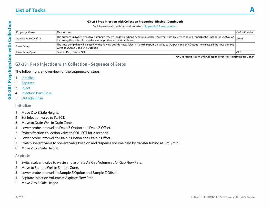
List of Tasks A
A-262 Gilson TRILUTION® LC Software v3.0 User’s Guide
GX-
281
Prep
Inje
ctio
n w
ith
Colle
ctio
n
GX-281 Prep Injection with Collection - Sequence of StepsThe following is an overview for the sequence of steps.
1 Initialize2 Aspirate3 Inject4 Injection Port Rinse5 Outside Rinse
Initialize1 Move Z to Z Safe Height.2 Set injection valve to INJECT.3 Move to Drain Well in Drain Zone.4 Lower probe into well to Drain Z Option and Drain Z Offset.5 Switch fraction collection valve to COLLECT for 2 seconds.6 Lower probe into well to Drain Z Option and Drain Z Offset.7 Switch solvent valve to Solvent Valve Position and dispense volume held by transfer tubing at 5 mL/min.8 Move Z to Z Safe Height.
Aspirate1 Switch solvent valve to waste and aspirate Air Gap Volume at Air Gap Flow Rate.2 Move to Sample Well in Sample Zone.3 Lower probe into well to Sample Z Option and Sample Z Offset.4 Aspirate Injection Volume at Aspirate Flow Rate.5 Move Z to Z Safe Height.
Outside Rinse Z Offset The distance up (when a positive number is entered) or down (when a negative number is entered) from a reference point defined by the Outside Rinse Z Option for rinsing the probe at the outside rinse position in the rinse station. 2 mm
Rinse Pump The rinse pump that will be used for the flowing outside rinse. Select 1 if the rinse pump is wired to Output 1 and 24V Output 1 or select 2 if the rinse pump is wired to Output 2 and 24V Output 2. 1
Rinse Pump Speed Select HIGH, LOW, or OFF. OFF
GX-281 Prep Injection with Collection Properties - Rinsing (Continued)For information about rinse positions, refer to Appendix B, Rinse Locations.
Property Name Description Default Value
GX-281 Prep Injection with Collection Properties - Rinsing (Page 2 of 2)

Gilson TRILUTION® LC Software v3.0 User’s Guide A-263
List of Tasks AG
X-281 Prep Injection with Collection
Inject1 Move to Injection Well in Injection Zone.2 Lower probe into well to Injection Z Option and Injection Z Offset.3 Switch injection valve to LOAD.4 Wait 1.2 sec.5 Switch solvent valve to Solvent Valve Position and dispense Injection Volume + Push Volume at Dispense Flow Rate.6 Wait Injection Equilibration Time.7 Synchronize.8 Switch injection valve to INJECT.
Injection Port Rinse1 Switch solvent valve to Solvent Valve Position and dispense volume held by transfer tubing at 5 mL/min.2 Dispense Injection Rinse Volume at Injection Rinse Flow Rate.3 Move Z to Z Safe Height
Outside Rinse1 Move Z to Z Safe Height.2 Move to rinse station/well 1 in Outside Rinse Zone.3 Lower probe into well to Outside Rinse Z Option and Outside Rinse Z Offset.4 Switch Rinse Pump on at Rinse Pump Speed.5 Switch solvent valve to Rinse Well 1 Solvent Valve Position and dispense Outside Rinse Volume at Outside Rinse Flow Rate. If the current solvent valve position
is not the same as the previous solvent valve position, dispense Outside Rinse Volume + 2000 uL + Transfer Tubing volume.6 Switch Rinse Pump off.7 Move Z to Z Safe Height.8 Repeat steps 2–7 for the Number of Rinse Stations, incrementing the rinse station/well for each rinse station.

List of Tasks A
A-264 Gilson TRILUTION® LC Software v3.0 User’s Guide
GX-
281
Rack
Sca
n GX-281 Rack ScanThis task scans the racks on the locator plate of the GX-281 Liquid Handler for the purpose of ensuring that the rack hardware setup matches the software rack (bed layout) setup.
For more information about the properties on each tab, refer to:
GX-281 Rack Scan Properties
GX-281 Rack Scan Properties
Property Name Description Default Value
Liquid Handler The liquid handler that the task will affect. Liquid Handler
GX-281 Rack Scan Properties

Gilson TRILUTION® LC Software v3.0 User’s Guide A-265
List of Tasks AG
X-281 Total Loop Injection
GX-281 Total Loop InjectionThis task performs a total loop injection.
For more information about the properties on each tab, refer to:
GX-281 Total Loop Injection Properties - Main
GX-281 Total Loop Injection Properties - Rinsing
GX-281 Total Loop Injection - Sequence of Steps
GX-281 Total Loop Injection Properties - Main
Property Name Description Default Value
Liquid Handler The liquid handler that the task will affect. Liquid Handler
Pump The pump that the task will affect. Liquid Handler
Injector The injector or injection module that the task will affect. Liquid Handler
GX-281 Total Loop Injection Properties - Main (Page 1 of 3)

List of Tasks A
A-266 Gilson TRILUTION® LC Software v3.0 User’s Guide
GX-
281
Tota
l Loo
p In
ject
ion
Solvent Valve PositionThe desired position of the solvent selection valve on the GX Solvent System. Valid range is 1–6.
The position designated for waste cannot be used for a solvent.2
Valve IDEnter 2 for the Left GX Direct Injection Module.
Enter 3 for the Right GX Direct Injection Module.3
Sample Zone The zone from which the Extra Volume and Loop Volume are aspirated. Sample Zone
Sample Well Enter the well number in the Sample Zone. 0
Injection Zone The zone to which the Extra Volume and Loop Volume are dispensed. Injection Zone
Injection Well Enter the well number in the Injection Zone. 1
Air Gap Volume The quantity of an air gap. 50 μL
Extra Volume An additional volume to the first volume aspirated. It ensures that the actual volume of liquid to be transferred is not contaminated, and acts as an extra buffer between the air gap/reservoir solvent and the Loop Volume. 1000 μL
Loop Volume The capacity of the installed sample loop. 0 μL
Aspirate Flow Rate The speed at which liquid volumes move into the probe. 5 mL/min
Dispense Flow Rate The speed at which liquid volumes move out of the probe. 5 mL/min
Air Gap Flow Rate The speed at which the Air Gap Volume moves into the probe. 1 mL/min
Injection Equilibration Time The time the program waits after loading the Extra Volume and Loop Volume in the sample loop. 0.05 min
Sample Z Option
One of six defined reference points used when aspirating the Extra Volume and Loop Volume from the bed:Auto Calculate: Places probe into well and at the liquid level using initial volume from the sample list and well dimensions from the bed layout; accepts a positive (+) or negative (-) value for the Sample Z Offset.Absolute Value: Moves the probe to the Z-value entered; if 0 is entered, probe will move to the bed bottom (no safety factor incorporated).Tube Bottom: Moves the probe to the well bottom as defined by the bed layout; accepts only positive Sample Z Offset value to move up from the bottom.Top: Moves probe to the top of their Z-travel range; accepts only a negative (-) value for the Sample Z Offset.Tube Top: Moves the probe to the top of the well as defined by the bed layout; accepts a positive (+) or negative (-) value for the Sample Z Offset.Z Adjust: Moves the probe from the current position up (positive value) or down (negative value).
Tube Bottom
Sample Z Offset The distance up (when a positive number is entered) or down (when a negative number is entered) from a reference point defined by the Sample Z Option used when aspirating the Extra Volume and Loop Volume from the bed. 2 mm
Liquid Level FollowingWhen selected, the probe will follow the liquid down as it is aspirated from the Sample Zone. The Sample Z Option must be set to AUTO CALCULATE and initial volumes must be set in the sample list to use this option.
When cleared, the probe will not follow the liquid down as it is aspirated from the Sample Zone.Cleared
GX-281 Total Loop Injection Properties - Main (Continued)
Property Name Description Default Value
GX-281 Total Loop Injection Properties - Main (Page 2 of 3)

Gilson TRILUTION® LC Software v3.0 User’s Guide A-267
List of Tasks AG
X-281 Total Loop Injection
Injection Z Option
One of six defined reference points used when performing the injection:Auto Calculate: Places probe into well and at the liquid level using initial volume from the sample list and well dimensions from the bed layout; accepts a positive (+) or negative (-) value for the Injection Z Offset.Absolute Value: Moves the probe to the Z-value entered; if 0 is entered for the Injection Z Offset, probe will move to the bed bottom (no safety factor incorporated).Tube Bottom: Moves the probe to the well bottom as defined by the bed layout; accepts only positive Injection Z Offset values to move up from the bottom.Top: Moves probe to the top of their Z-travel range; accepts only a negative (-) value for the Injection Z Offset.Tube Top: Moves the probe to the top of the well as defined by the bed layout; accepts a positive (+) or negative (-) value for the Injection Z Offset.Z Adjust: Moves the probe from the current position up (positive value) or down (negative value).
Tube Bottom
Injection Z Offset The distance up (when a positive number is entered) or down (when a negative number is entered) from a reference point defined by the Injection Z Option when performing the injection. 0
GX-281 Total Loop Injection Properties - Rinsing For information about rinse positions, refer to Appendix B, Rinse Locations.
Property Name Description Default Value
Drain Zone The zone in which the GX Solvent System is homed. Inside Rinse
Drain Well Enter the well number in the Drain Zone. 1
Drain Z Option
One of six defined reference points used when purging to the drain:Auto Calculate: Places probe into well and at the liquid level using initial volume from the sample list and well dimensions from the bed layout; accepts a positive (+) or negative (-) value for the Drain Z Offset.Absolute Value: Moves the probe to the Z-value entered; if 0 is entered for the Drain Z Offset, probe will move to the bed bottom (no safety factor incorporated).Tube Bottom: Moves the probe to the well bottom as defined by the bed layout; accepts only positive Drain Z Offset values to move up from the bottom.Top: Moves probe to the top of their Z-travel range; accepts only a negative (-) value for the Drain Z Offset.Tube Top: Moves the probe to the top of the well as defined by the bed layout; accepts a positive (+) or negative (-) value for the Drain Z Offset.Z Adjust: Moves the probe from the current position up (positive value) or down (negative value).
Tube Top
Drain Z Offset The distance up (when a positive number is entered) or down (when a negative number is entered) from a reference point defined by the Drain Z Option for purging to the drain. -7
Injection Rinse Volume The quantity of liquid used to rinse the injection port at Injection Well in Injection Zone. 1000 μL
Injection Rinse Flow Rate The speed at which the Injection Rinse Volume moves out of the probe and into the injection port. 5 mL/min
Outside Rinse Zone The zone to which the Outside Rinse Volume is delivered. Outside Rinse
Number of Rinse Stations Select the number of rinse stations to be used when performing the outside rinse. Valid range is 1–5. 1
Rinse Well 1 Solvent Valve PositionThe desired position of the solvent selection valve on the GX Solvent System during the outside rinse at rinse station 1. Valid range is 1–6.
The position designated for waste cannot be used for a solvent.2
Rinse Well 2 Solvent Valve PositionThe desired position of the solvent selection valve on the GX Solvent System during the outside rinse at rinse station 2. Valid range is 1–6.
The position designated for waste cannot be used for a solvent.2
Rinse Well 3 Solvent Valve PositionThe desired position of the solvent selection valve on the GX Solvent System during the outside rinse at rinse station 3. Valid range is 1–6.
The position designated for waste cannot be used for a solvent.2
GX-281 Total Loop Injection Properties - Rinsing (Page 1 of 2)
GX-281 Total Loop Injection Properties - Main (Continued)
Property Name Description Default Value
GX-281 Total Loop Injection Properties - Main (Page 3 of 3)

List of Tasks A
A-268 Gilson TRILUTION® LC Software v3.0 User’s Guide
GX-
281
Tota
l Loo
p In
ject
ion
Rinse Well 4 Solvent Valve PositionThe desired position of the solvent selection valve on the GX Solvent System during the outside rinse at rinse station 4. Valid range is 1–6.
The position designated for waste cannot be used for a solvent.2
Rinse Well 5 Solvent Valve PositionThe desired position of the solvent selection valve on the GX Solvent System during the outside rinse at rinse station 5. Valid range is 1–6.
The position designated for waste cannot be used for a solvent.2
Outside Rinse Volume The quantity of liquid used to rinse the outside of the probe. 2000 μL
Outside Rinse Flow Rate The speed at which the Outside Rinse Volume moves out of the probe and into the outside rinse position in the rinse station. 5 mL/min
Outside Rinse Z Option
One of six defined reference points used when performing the outside rinse:Auto Calculate: Places probe into well and at the liquid level using initial volume from the sample list and well dimensions from the bed layout; accepts a positive (+) or negative (-) value for the Outside Rinse Z Offset.Absolute Value: Moves the probe to the Z-value entered; if 0 is entered for the Outside Rinse Z Offset, the probe will move to the bed bottom (no safety factor incorporated).Tube Bottom: Moves the probe to the well bottom as defined by the bed layout; accepts only positive Outside Rinse Z Offset values to move up from the bottom.Top: Moves probe to the top of their Z-travel range; accepts only a negative (-) value for the Outside Rinse Z Offset.Tube Top: Moves the probe to the top of the well as defined by the bed layout; accepts a positive (+) or negative (-) value for the Outside Rinse Z Offset.
Tube Bottom
Outside Rinse Z Offset The distance up (when a positive number is entered) or down (when a negative number is entered) from a reference point defined by the Outside Rinse Z Option for rinsing the probe at the outside rinse position in the rinse station. 2 mm
Rinse Pump The rinse pump that will be used for the flowing outside rinse. Select 1 if the rinse pump is wired to Output 1 and 24V Output 1 or select 2 if the rinse pump is wired to Output 2 and 24V Output 2. 1
Rinse Pump Speed Select HIGH, LOW, or OFF. OFF
GX-281 Total Loop Injection Properties - Rinsing (Continued)For information about rinse positions, refer to Appendix B, Rinse Locations.
Property Name Description Default Value
GX-281 Total Loop Injection Properties - Rinsing (Page 2 of 2)

Gilson TRILUTION® LC Software v3.0 User’s Guide A-269
List of Tasks AG
X-281 Total Loop Injection
GX-281 Total Loop Injection - Sequence of StepsThe following is an overview for the sequence of steps.
1 Initialize2 Aspirate3 Inject4 Injection Port Rinse5 Outside Rinse
Initialize1 Move Z to Z Safe Height.2 Set injection valve to INJECT.3 Move to Drain Well in Drain Zone.4 Lower probe into well to Drain Z Option and Drain Z Offset.5 Switch solvent valve to Solvent Valve Position and dispense volume held by transfer tubing at 5 mL/min.6 Move Z to Z Safe Height.
Aspirate1 Switch solvent valve to waste and aspirate Air Gap Volume at Air Gap Flow Rate.2 Move to Sample Well in Sample Zone.3 Lower probe into well to Sample Z Option and Sample Z Offset.4 Aspirate Loop Volume + Extra Volume at Aspirate Flow Rate.5 Move Z to Z Safe Height.
Inject1 Move to Injection Well in Injection Zone.2 Lower probe to Injection Z Option and Injection Z Offset.3 Switch injection valve to LOAD.4 Wait 1.2 sec.5 Switch solvent valve to Solvent Valve Position and dispense Loop Volume + 1/2 Extra Volume at Dispense Flow Rate.6 Wait Injection Equilibration Time.7 Synchronize.8 Switch injection valve to INJECT.

List of Tasks A
A-270 Gilson TRILUTION® LC Software v3.0 User’s Guide
GX-
281
Tota
l Loo
p In
ject
ion Injection Port Rinse
1 Switch solvent valve to Solvent Valve Position and dispense volume held by transfer tubing at 5 mL/min.2 Dispense Injection Rinse Volume at Injection Rinse Flow Rate.3 Move Z to Z Safe Height
Outside Rinse1 Move Z to Z Safe Height.2 Move to rinse station/well 1 in Outside Rinse Zone.3 Lower probe into well to Outside Rinse Z Option and Outside Rinse Z Offset.4 Switch Rinse Pump on at Rinse Pump Speed.5 Switch solvent valve to Rinse Well 1 Solvent Valve Position and dispense Outside Rinse Volume at Outside Rinse Flow Rate. If the current solvent valve position
is not the same as the previous solvent valve position, dispense Outside Rinse Volume + 2000 uL + Transfer Tubing volume.6 Switch Rinse Pump off.7 Move Z to Z Safe Height.8 Repeat steps 2–7 for the Number of Rinse Stations, incrementing the rinse station/well for each rinse station.

Gilson TRILUTION® LC Software v3.0 User’s Guide A-271
List of Tasks AG
X-281 w-o pum
p Low Volum
e Partial Loop Inject
GX-281 w-o pump Low Volume Partial Loop InjectThis task performs a partial loop injection using a push volume from the reservoir to push the injection volume into the sample loop.
For more information about the properties on each tab, refer to:
GX-281 w-o pump Low Volume Partial Loop Inject Properties - Main
GX-281 w-o pump Low Volume Partial Loop Inject Properties - Advanced
GX-281 w-o pump Low Volume Partial Loop Inject Properties - Rinsing
GX-281 w-o pump Low Volume Partial Loop Inject - Sequence of Steps
GX-281 w-o pump Low Volume Partial Loop Inject Properties - Main
Property Name Description Default Value
Liquid Handler The liquid handler that the task will affect. Liquid Handler
Pump The pump that the task will affect. Pump
Injector The injector or injection module that the task will affect. Liquid Handler
Valve IDEnter 2 for the Left GX Direct Injection Module.
Enter 3 for the Right GX Direct Injection Module.3
Sample Zone The zone from which the Injection Volume and Extra Volume are aspirated. Sample Zone
GX-281 w-o pump Low Volume Partial Loop Inject Properties - Main (Page 1 of 2)
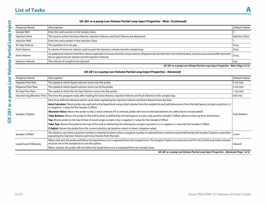
List of Tasks A
A-272 Gilson TRILUTION® LC Software v3.0 User’s Guide
GX-
281
w-o
pum
p Lo
w V
olum
e Pa
rtia
l Loo
p In
ject
Sample Well Enter the well number in the Sample Zone. 0
Injection Zone The zone to which the Extra Volume, Injection Volume, and Push Volume are dispensed. Injection Zone
Injection Well Enter the well number in the Injection Zone. 1
Air Gap Volume The quantity of an air gap. 50 μL
Push Volume A volume of reservoir solvent used to push the injection volume into the sample loop. 20 μL
Extra Volume An additional volume to the first volume aspirated. It ensures that the actual volume of liquid to be transferred is not contaminated, and acts as an extra buffer between the air gap/reservoir solvent and the Injection Volume. 25 μL
Injection Volume The volume of sample to be injected. 0 μL
GX-281 w-o pump Low Volume Partial Loop Inject Properties - Advanced
Property Name Description Default Value
Aspirate Flow Rate The speed at which liquid volumes move into the probe. 5 mL/min
Dispense Flow Rate The speed at which liquid volumes move out of the probe. 5 mL/min
Air Gap Flow Rate The speed at which the Air Gap Volume moves into the probe. 1 mL/min
Injection Equilibration Time The time the program waits after loading the Extra Volume, Injection Volume and Push Volume in the sample loop. 0.05 min
Sample Z Option
One of six defined reference points used when aspirating the Injection Volume and Extra Volume from the bed:
Auto Calculate: Places probe into well and at the liquid level using initial volume from the sample list and well dimensions from the bed layout; accepts a positive (+) or negative (-) value for the Sample Z Offset.
Absolute Value: Moves the probe to the Z-value entered; if 0 is entered, probe will move to the bed bottom (no safety factor incorporated).
Tube Bottom: Moves the probe to the well bottom as defined by the bed layout; accepts only positive Sample Z Offset value to move up from the bottom.
Top: Moves probe to the top of their Z-travel range; accepts only a negative (-) value for the Sample Z Offset.
Tube Top: Moves the probe to the top of the well as defined by the bed layout; accepts a positive (+) or negative (-) value for the Sample Z Offset.
Z Adjust: Moves the probe from the current position up (positive value) or down (negative value).
Tube Bottom
Sample Z Offset The distance up (when a positive number is entered) or down (when a negative number is entered) from a reference point defined by the Sample Z Option used when aspirating the Injection Volume and Extra Volume from the bed. 2 mm
Liquid Level FollowingWhen selected, the probe will follow the liquid down as it is aspirated from the Sample Zone. The Sample Z Option must be set to AUTO CALCULATE and initial volumes must be set in the sample list to use this option.
When cleared, the probe will not follow the liquid down as it is aspirated from the Sample Zone.Cleared
GX-281 w-o pump Low Volume Partial Loop Inject Properties - Advanced (Page 1 of 2)
GX-281 w-o pump Low Volume Partial Loop Inject Properties - Main (Continued)
Property Name Description Default Value
GX-281 w-o pump Low Volume Partial Loop Inject Properties - Main (Page 2 of 2)

Gilson TRILUTION® LC Software v3.0 User’s Guide A-273
List of Tasks AG
X-281 w-o pum
p Low Volum
e Partial Loop Inject
Injection Z Option
One of six defined reference points used when performing the injection:
Auto Calculate: Places probe into well and at the liquid level using initial volume from the sample list and well dimensions from the bed layout; accepts a positive (+) or negative (-) value for the Injection Z Offset.
Absolute Value: Moves the probe to the Z-value entered; if 0 is entered for the Injection Z Offset, probe will move to the bed bottom (no safety factor incorporated).
Tube Bottom: Moves the probe to the well bottom as defined by the bed layout; accepts only positive Injection Z Offset values to move up from the bottom.
Top: Moves probe to the top of their Z-travel range; accepts only a negative (-) value for the Injection Z Offset.
Tube Top: Moves the probe to the top of the well as defined by the bed layout; accepts a positive (+) or negative (-) value for the Injection Z Offset.
Z Adjust: Moves the probe from the current position up (positive value) or down (negative value).
Tube Bottom
Injection Z Offset The distance up (when a positive number is entered) or down (when a negative number is entered) from a reference point defined by the Injection Z Option when performing the injection.
0
GX-281 w-o pump Low Volume Partial Loop Inject Properties - Rinsing For information about rinse positions, refer to Appendix B, Rinse Locations.
Property Name Description Default Value
Drain Zone The zone in which the dilutor is homed. Inside Rinse
Drain Well Enter the well number in the Drain Zone. 1
Drain Z Option
One of six defined reference points used when purging to the drain:Auto Calculate: Places probe into well and at the liquid level using initial volume from the sample list and well dimensions from the bed layout; accepts a positive (+) or negative (-) value for the Drain Z Offset.Absolute Value: Moves the probe to the Z-value entered; if 0 is entered for the Drain Z Offset, probe will move to the bed bottom (no safety factor incorporated).Tube Bottom: Moves the probe to the well bottom as defined by the bed layout; accepts only positive Drain Z Offset values to move up from the bottom.Top: Moves probe to the top of their Z-travel range; accepts only a negative (-) value for the Drain Z Offset.Tube Top: Moves the probe to the top of the well as defined by the bed layout; accepts a positive (+) or negative (-) value for the Drain Z Offset.Z Adjust: Moves the probe from the current position up (positive value) or down (negative value).
Tube Top
Drain Z Offset The distance up (when a positive number is entered) or down (when a negative number is entered) from a reference point defined by the Drain Z Option for purging to the drain. -7
Injection Rinse Volume The quantity of liquid used to rinse the injection port at Injection Well in Injection Zone. 1000 μL
Injection Rinse Flow Rate The speed at which the Injection Rinse Volume moves out of the probe and into the injection port. 5 mL/min
Outside Rinse Zone The zone to which the Outside Rinse Volume is delivered. Outside Rinse
Outside Rinse Well Enter the well number in the Outside Rinse Zone. 1
Outside Rinse Volume The quantity of liquid used to rinse the outside of the probe. 2000 μL
Outside Rinse Flow Rate The speed at which the Outside Rinse Volume moves out of the probe and into the outside rinse position in the rinse station. 5 mL/min
GX-281 w-o pump Low Volume Partial Loop Inject (Page 1 of 2)
GX-281 w-o pump Low Volume Partial Loop Inject Properties - Advanced (Continued)
Property Name Description Default Value
GX-281 w-o pump Low Volume Partial Loop Inject Properties - Advanced (Page 2 of 2)

List of Tasks A
A-274 Gilson TRILUTION® LC Software v3.0 User’s Guide
GX-
281
w-o
pum
p Lo
w V
olum
e Pa
rtia
l Loo
p In
ject
GX-281 w-o pump Low Volume Partial Loop Inject - Sequence of StepsThe following is an overview for the sequence of steps.
1 Initialize2 Aspirate3 Inject4 Injection Port Rinse5 Outside Rinse
Initialize1 Move Z to Z Safe Height.2 Set injection valve to INJECT.3 Move to Drain Well in Drain Zone.4 Lower probe into well to Drain Z Option and Drain Z Offset.5 Home dilutor.6 Move Z to Z Safe Height.
Outside Rinse Z Option
One of six defined reference points used when performing the outside rinse:Auto Calculate: Places probe into well and at the liquid level using initial volume from the sample list and well dimensions from the bed layout; accepts a positive (+) or negative (-) value for the Outside Rinse Z Offset.Absolute Value: Moves the probe to the Z-value entered; if 0 is entered for the Outside Rinse Z Offset, the probe will move to the bed bottom (no safety factor incorporated).Tube Bottom: Moves the probe to the well bottom as defined by the bed layout; accepts only positive Outside Rinse Z Offset values to move up from the bottom.Top: Moves probe to the top of their Z-travel range; accepts only a negative (-) value for the Outside Rinse Z Offset.Tube Top: Moves the probe to the top of the well as defined by the bed layout; accepts a positive (+) or negative (-) value for the Outside Rinse Z Offset.Z Adjust: Moves the probe from the current position up (positive value) or down (negative value).
Tube Bottom
Outside Rinse Z Offset The distance up (when a positive number is entered) or down (when a negative number is entered) from a reference point defined by the Outside Rinse Z Option for rinsing the probe at the outside rinse position in the rinse station.
2 mm
GX-281 w-o pump Low Volume Partial Loop Inject Properties - Rinsing (Continued)For information about rinse positions, refer to Appendix B, Rinse Locations.
Property Name Description Default Value
GX-281 w-o pump Low Volume Partial Loop Inject (Page 2 of 2)
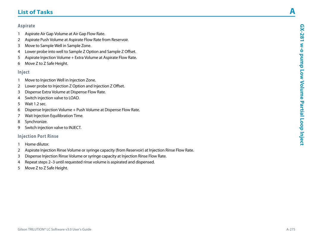
Gilson TRILUTION® LC Software v3.0 User’s Guide A-275
List of Tasks AG
X-281 w-o pum
p Low Volum
e Partial Loop Inject
Aspirate1 Aspirate Air Gap Volume at Air Gap Flow Rate.2 Aspirate Push Volume at Aspirate Flow Rate from Reservoir.3 Move to Sample Well in Sample Zone.4 Lower probe into well to Sample Z Option and Sample Z Offset.5 Aspirate Injection Volume + Extra Volume at Aspirate Flow Rate.6 Move Z to Z Safe Height.
Inject1 Move to Injection Well in Injection Zone.2 Lower probe to Injection Z Option and Injection Z Offset.3 Dispense Extra Volume at Dispense Flow Rate.4 Switch injection valve to LOAD.5 Wait 1.2 sec.6 Dispense Injection Volume + Push Volume at Dispense Flow Rate.7 Wait Injection Equilibration Time.8 Synchronize.9 Switch injection valve to INJECT.
Injection Port Rinse1 Home dilutor.2 Aspirate Injection Rinse Volume or syringe capacity (from Reservoir) at Injection Rinse Flow Rate.3 Dispense Injection Rinse Volume or syringe capacity at Injection Rinse Flow Rate.4 Repeat steps 2–3 until requested rinse volume is aspirated and dispensed.5 Move Z to Z Safe Height.

List of Tasks A
A-276 Gilson TRILUTION® LC Software v3.0 User’s Guide
GX-
281
w-o
pum
p Lo
w V
olum
e Pa
rtia
l Loo
p In
ject Outside Rinse
1 Move to Outside Rinse Well in Outside Rinse Zone.2 Lower probe into well to Outside Rinse Z Option and Outside Rinse Z Offset.3 Home dilutor.4 Aspirate Outside Rinse Volume or syringe capacity (from Reservoir) at Outside Rinse Flow Rate.5 Dispense Outside Rinse Volume or syringe capacity at Outside Rinse Flow Rate.6 Repeat steps 4–5 until requested rinse volume is aspirated and dispensed.7 Move Z to Safe Height.

Gilson TRILUTION® LC Software v3.0 User’s Guide A-277
List of Tasks AG
X-281 w-o pum
p Partial Loop Injection
GX-281 w-o pump Partial Loop InjectionThis task performs a partial loop injection.
For more information about the properties on each tab, refer to:
GX-281 w-o pump Partial Loop Inject Properties - Main
GX-281 w-o pump Partial Loop Inject Properties - Advanced
GX-281 w-o pump Partial Loop Inject Properties - Rinsing
GX-281 w-o pump Partial Loop Injection - Sequence of Steps
GX-281 w-o pump Partial Loop Inject Properties - Main
Property Name Description Default Value
Liquid Handler The liquid handler that the task will affect. Liquid Handler
Pump The pump that the task will affect. Pump
Injector The injector or injection module that the task will affect. Liquid Handler
Valve IDEnter 2 for the Left GX Direct Injection Module.
Enter 3 for the Right GX Direct Injection Module.3
GX-281 w-o pump Partial Loop Inject Properties - Main (Page 1 of 2)

List of Tasks A
A-278 Gilson TRILUTION® LC Software v3.0 User’s Guide
GX-
281
w-o
pum
p Pa
rtia
l Loo
p In
ject
ion
Sample Zone The zone from which the Injection Volume and Extra Volume are aspirated. Sample Zone
Sample Well Enter the well number in the Sample Zone. 0
Injection Zone The zone to which the Extra Volume and Injection Volume are dispensed. Injection Zone
Injection Well Enter the well number in the Injection Zone. 1
Air Gap Volume The quantity of an air gap. 50 μL
Extra Volume An additional volume to the first volume aspirated. It ensures that the actual volume of liquid to be transferred is not contaminated, and acts as an extra buffer between the air gap/reservoir solvent and the Injection Volume. 20 μL
Injection Volume The volume of sample to be injected. 0 μL
GX-281 w-o pump Partial Loop Inject Properties - Advanced
Property Name Description Default Value
Aspirate Flow Rate The speed at which liquid volumes move into the probe. 5 mL/min
Dispense Flow Rate The speed at which liquid volumes move out of the probe. 5 mL/min
Air Gap Flow Rate The speed at which the Air Gap Volume moves into the probe. 1 mL/min
Injection Equilibration Time The time the program waits after loading the Extra Volume and Injection Volume in the sample loop. 0.05 min
Sample Z Option
One of six defined reference points used when aspirating the Injection Volume and Extra Volume from the bed:
Auto Calculate: Places probe into well and at the liquid level using initial volume from the sample list and well dimensions from the bed layout; accepts a positive (+) or negative (-) value for the Sample Z Offset.
Absolute Value: Moves the probe to the Z-value entered; if 0 is entered, probe will move to the bed bottom (no safety factor incorporated).
Tube Bottom: Moves the probe to the well bottom as defined by the bed layout; accepts only positive Sample Z Offset value to move up from the bottom.
Top: Moves probe to the top of their Z-travel range; accepts only a negative (-) value for the Sample Z Offset.
Tube Top: Moves the probe to the top of the well as defined by the bed layout; accepts a positive (+) or negative (-) value for the Sample Z Offset.
Z Adjust: Moves the probe from the current position up (positive value) or down (negative value).
Tube Bottom
Sample Z Offset The distance up (when a positive number is entered) or down (when a negative number is entered) from a reference point defined by the Sample Z Option used when aspirating the Injection Volume and Extra Volume from the bed. 2 mm
Liquid Level FollowingWhen selected, the probe will follow the liquid down as it is aspirated from the Sample Zone. The Sample Z Option must be set to AUTO CALCULATE and initial volumes must be set in the sample list to use this option.
When cleared, the probe will not follow the liquid down as it is aspirated from the Sample Zone.Cleared
GX-281 w-o pump Partial Loop Inject Properties - Advanced (Page 1 of 2)
GX-281 w-o pump Partial Loop Inject Properties - Main (Continued)
Property Name Description Default Value
GX-281 w-o pump Partial Loop Inject Properties - Main (Page 2 of 2)

Gilson TRILUTION® LC Software v3.0 User’s Guide A-279
List of Tasks AG
X-281 w-o pum
p Partial Loop Injection
Injection Z Option
One of six defined reference points used when performing the injection:
Auto Calculate: Places probe into well and at the liquid level using initial volume from the sample list and well dimensions from the bed layout; accepts a positive (+) or negative (-) value for the Injection Z Offset.
Absolute Value: Moves the probe to the Z-value entered; if 0 is entered for the Injection Z Offset, probe will move to the bed bottom (no safety factor incorporated).
Tube Bottom: Moves the probe to the well bottom as defined by the bed layout; accepts only positive Injection Z Offset values to move up from the bottom.
Top: Moves probe to the top of their Z-travel range; accepts only a negative (-) value for the Injection Z Offset.
Tube Top: Moves the probe to the top of the well as defined by the bed layout; accepts a positive (+) or negative (-) value for the Injection Z Offset.
Z Adjust: Moves the probe from the current position up (positive value) or down (negative value).
Tube Bottom
Injection Z Offset The distance up (when a positive number is entered) or down (when a negative number is entered) from a reference point defined by the Injection Z Option when performing the injection.
0
GX-281 w-o pump Partial Loop Inject Properties - Rinsing For information about rinse positions, refer to Appendix B, Rinse Locations.
Property Name Description Default Value
Drain Zone The zone in which the dilutor is homed. Inside Rinse
Drain Well Enter the well number in the Drain Zone. 1
Drain Z Option
One of six defined reference points used when purging to the drain:Auto Calculate: Places probe into well and at the liquid level using initial volume from the sample list and well dimensions from the bed layout; accepts a positive (+) or negative (-) value for the Drain Z Offset.Absolute Value: Moves the probe to the Z-value entered; if 0 is entered for the Drain Z Offset, probe will move to the bed bottom (no safety factor incorporated).Tube Bottom: Moves the probe to the well bottom as defined by the bed layout; accepts only positive Drain Z Offset values to move up from the bottom.Top: Moves probe to the top of their Z-travel range; accepts only a negative (-) value for the Drain Z Offset.Tube Top: Moves the probe to the top of the well as defined by the bed layout; accepts a positive (+) or negative (-) value for the Drain Z Offset.Z Adjust: Moves the probe from the current position up (positive value) or down (negative value).
Tube Top
Drain Z Offset The distance up (when a positive number is entered) or down (when a negative number is entered) from a reference point defined by the Drain Z Option for purging to the drain. -7
Injection Rinse Volume The quantity of liquid used to rinse the injection port at Injection Well in Injection Zone. 1000 μL
Injection Rinse Flow Rate The speed at which the Injection Rinse Volume moves out of the probe and into the injection port. 5 mL/min
Outside Rinse Zone The zone to which the Outside Rinse Volume is delivered. Outside Rinse
Outside Rinse Well Enter the well number in the Outside Rinse Zone. 1
Outside Rinse Volume The quantity of liquid used to rinse the outside of the probe. 2000 μL
Outside Rinse Flow Rate The speed at which the Outside Rinse Volume moves out of the probe and into the outside rinse position in the rinse station. 5 mL/min
GX-281 w-o pump Partial Loop Inject - Rinsing (Page 1 of 2)
GX-281 w-o pump Partial Loop Inject Properties - Advanced (Continued)
Property Name Description Default Value
GX-281 w-o pump Partial Loop Inject Properties - Advanced (Page 2 of 2)

List of Tasks A
A-280 Gilson TRILUTION® LC Software v3.0 User’s Guide
GX-
281
w-o
pum
p Pa
rtia
l Loo
p In
ject
ion
GX-281 w-o pump Partial Loop Injection - Sequence of StepsThe following is an overview for the sequence of steps.
1 Initialize2 Aspirate3 Inject4 Injection Port Rinse5 Outside Rinse
Initialize1 Move Z to Z Safe Height.2 Set injection valve to INJECT.3 Move to Drain Well in Drain Zone.4 Lower probe into well to Drain Z Option and Drain Z Offset.5 Home dilutor.6 Move Z to Z Safe Height.
Outside Rinse Z Option
One of six defined reference points used when performing the outside rinse:Auto Calculate: Places probe into well and at the liquid level using initial volume from the sample list and well dimensions from the bed layout; accepts a positive (+) or negative (-) value for the Outside Rinse Z Offset.Absolute Value: Moves the probe to the Z-value entered; if 0 is entered for the Outside Rinse Z Offset, the probe will move to the bed bottom (no safety factor incorporated).Tube Bottom: Moves the probe to the well bottom as defined by the bed layout; accepts only positive Outside Rinse Z Offset values to move up from the bottom.Top: Moves probe to the top of their Z-travel range; accepts only a negative (-) value for the Outside Rinse Z Offset.Tube Top: Moves the probe to the top of the well as defined by the bed layout; accepts a positive (+) or negative (-) value for the Outside Rinse Z Offset.Z Adjust: Moves the probe from the current position up (positive value) or down (negative value).
Tube Bottom
Outside Rinse Z Offset The distance up (when a positive number is entered) or down (when a negative number is entered) from a reference point defined by the Outside Rinse Z Option for rinsing the probe at the outside rinse position in the rinse station.
2 mm
GX-281 w-o pump Partial Loop Inject Properties - Rinsing (Continued)For information about rinse positions, refer to Appendix B, Rinse Locations.
Property Name Description Default Value
GX-281 w-o pump Partial Loop Inject - Rinsing (Page 2 of 2)

Gilson TRILUTION® LC Software v3.0 User’s Guide A-281
List of Tasks AG
X-281 w-o pum
p Partial Loop Injection
Aspirate1 Aspirate Air Gap Volume at Air Gap Flow Rate.2 Move to Sample Well in Sample Zone.3 Lower probe into well to Sample Z Option and Sample Z Offset.4 Aspirate Injection Volume + Extra Volume at Aspirate Flow Rate.5 Move Z to Z Safe Height.
Inject1 Move to Injection Well in Injection Zone.2 Lower probe to Injection Z Option and Injection Z Offset.3 Dispense Extra Volume at Dispense Flow Rate.4 Switch injection valve to LOAD.5 Wait 1.2 sec.6 Dispense Injection Volume at Dispense Flow Rate.7 Wait Injection Equilibration Time.8 Synchronize.9 Switch injection valve to INJECT.
Injection Port Rinse1 Home dilutor.2 Aspirate Injection Rinse Volume or syringe capacity (from Reservoir) at Injection Rinse Flow Rate.3 Dispense Injection Rinse Volume or syringe capacity at Injection Rinse Flow Rate.4 Repeat steps 2–3 until requested rinse volume is aspirated and dispensed.5 Move Z to Z Safe Height
Outside Rinse1 Move to Outside Rinse Well in Outside Rinse Zone.2 Lower probe into well to Outside Rinse Z Option and Outside Rinse Z Offset.3 Home dilutor.4 Aspirate Outside Rinse Volume or syringe capacity (from Reservoir) at Outside Rinse Flow Rate.5 Dispense Outside Rinse Volume or syringe capacity at Outside Rinse Flow Rate.6 Repeat steps 4–5 until requested rinse volume is aspirated and dispensed.7 Move Z to Safe Height.
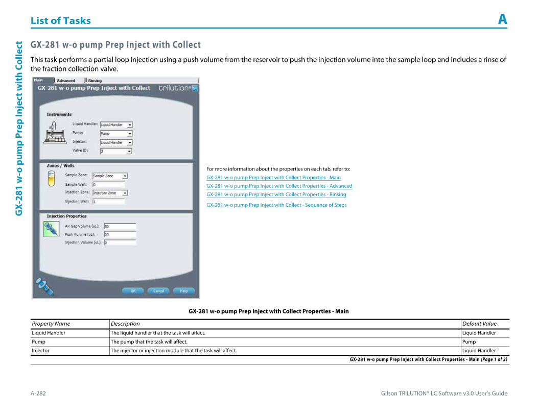
List of Tasks A
A-282 Gilson TRILUTION® LC Software v3.0 User’s Guide
GX-
281
w-o
pum
p Pr
ep In
ject
wit
h Co
llect GX-281 w-o pump Prep Inject with Collect
This task performs a partial loop injection using a push volume from the reservoir to push the injection volume into the sample loop and includes a rinse of the fraction collection valve.
For more information about the properties on each tab, refer to:
GX-281 w-o pump Prep Inject with Collect Properties - Main
GX-281 w-o pump Prep Inject with Collect Properties - Advanced
GX-281 w-o pump Prep Inject with Collect Properties - Rinsing
GX-281 w-o pump Prep Inject with Collect - Sequence of Steps
GX-281 w-o pump Prep Inject with Collect Properties - Main
Property Name Description Default Value
Liquid Handler The liquid handler that the task will affect. Liquid Handler
Pump The pump that the task will affect. Pump
Injector The injector or injection module that the task will affect. Liquid Handler
GX-281 w-o pump Prep Inject with Collect Properties - Main (Page 1 of 2)

Gilson TRILUTION® LC Software v3.0 User’s Guide A-283
List of Tasks AG
X-281 w-o pum
p Prep Inject with Collect
Valve IDEnter 2 for the Left GX Direct Injection Module.
Enter 3 for the Right GX Direct Injection Module.3
Sample Zone The zone from which the Injection Volume is aspirated. Sample Zone
Sample Well Enter the well number in the Sample Zone. 0
Injection Zone The zone to which the Injection Volume and Push Volume are dispensed. Injection Zone
Injection Well Enter the well number in the Injection Zone. 1
Air Gap Volume The quantity of an air gap. 50 μL
Push Volume A volume of reservoir solvent used to push the injection volume into the sample loop. 20 μL
Injection Volume The volume of sample to be injected. 0 μL
GX-281 w-o pump Prep Inject with Collect Properties - Advanced
Property Name Description Default Value
Aspirate Flow Rate The speed at which liquid volumes move into the probe. 5 mL/min
Dispense Flow Rate The speed at which liquid volumes move out of the probe. 5 mL/min
Air Gap Flow Rate The speed at which the Air Gap Volume moves into the probe. 1 mL/min
Injection Equilibration Time The time the program waits after loading the Injection Volume and Push Volume in the sample loop. 0.05 min
Sample Z Option
One of six defined reference points used when aspirating the Injection Volume from the bed:
Auto Calculate: Places probe into well and at the liquid level using initial volume from the sample list and well dimensions from the bed layout; accepts a positive (+) or negative (-) value for the Sample Z Offset.
Absolute Value: Moves the probe to the Z-value entered; if 0 is entered, probe will move to the bed bottom (no safety factor incorporated).
Tube Bottom: Moves the probe to the well bottom as defined by the bed layout; accepts only positive Sample Z Offset value to move up from the bottom.
Top: Moves probe to the top of their Z-travel range; accepts only a negative (-) value for the Sample Z Offset.
Tube Top: Moves the probe to the top of the well as defined by the bed layout; accepts a positive (+) or negative (-) value for the Sample Z Offset.
Z Adjust: Moves the probe from the current position up (positive value) or down (negative value).
Tube Bottom
Sample Z Offset The distance up (when a positive number is entered) or down (when a negative number is entered) from a reference point defined by the Sample Z Option used when aspirating the Injection Volume from the bed. 2 mm
Liquid Level FollowingWhen selected, the probe will follow the liquid down as it is aspirated from the Sample Zone. The Sample Z Option must be set to AUTO CALCULATE and initial volumes must be set in the sample list to use this option.
When cleared, the probe will not follow the liquid down as it is aspirated from the Sample Zone.Cleared
GX-281 w-o pump Prep Inject with Collect Properties - Advanced (Page 1 of 2)
GX-281 w-o pump Prep Inject with Collect Properties - Main (Continued)
Property Name Description Default Value
GX-281 w-o pump Prep Inject with Collect Properties - Main (Page 2 of 2)

List of Tasks A
A-284 Gilson TRILUTION® LC Software v3.0 User’s Guide
GX-
281
w-o
pum
p Pr
ep In
ject
wit
h Co
llect
Injection Z Option
One of six defined reference points used when performing the injection:
Auto Calculate: Places probe into well and at the liquid level using initial volume from the sample list and well dimensions from the bed layout; accepts a positive (+) or negative (-) value for the Injection Z Offset.
Absolute Value: Moves the probe to the Z-value entered; if 0 is entered for the Injection Z Offset, probe will move to the bed bottom (no safety factor incorporated).
Tube Bottom: Moves the probe to the well bottom as defined by the bed layout; accepts only positive Injection Z Offset values to move up from the bottom.
Top: Moves probe to the top of their Z-travel range; accepts only a negative (-) value for the Injection Z Offset.
Tube Top: Moves the probe to the top of the well as defined by the bed layout; accepts a positive (+) or negative (-) value for the Injection Z Offset.
Z Adjust: Moves the probe from the current position up (positive value) or down (negative value).
Tube Bottom
Injection Z Offset The distance up (when a positive number is entered) or down (when a negative number is entered) from a reference point defined by the Injection Z Option when performing the injection. 0
GX-281 w-o pump Prep Inject with Collect Properties - Rinsing For information about rinse positions, refer to Appendix B, Rinse Locations.
Property Name Description Default Value
Drain Zone The zone in which the dilutor is homed. Inside Rinse
Drain Well Enter the well number in the Drain Zone. 1
Drain Z Option
One of six defined reference points used when purging to the drain:Auto Calculate: Places probe into well and at the liquid level using initial volume from the sample list and well dimensions from the bed layout; accepts a positive (+) or negative (-) value for the Drain Z Offset.Absolute Value: Moves the probe to the Z-value entered; if 0 is entered for the Drain Z Offset, probe will move to the bed bottom (no safety factor incorporated).Tube Bottom: Moves the probe to the well bottom as defined by the bed layout; accepts only positive Drain Z Offset values to move up from the bottom.Top: Moves probe to the top of their Z-travel range; accepts only a negative (-) value for the Drain Z Offset.Tube Top: Moves the probe to the top of the well as defined by the bed layout; accepts a positive (+) or negative (-) value for the Drain Z Offset.Z Adjust: Moves the probe from the current position up (positive value) or down (negative value).
Tube Top
Drain Z Offset The distance up (when a positive number is entered) or down (when a negative number is entered) from a reference point defined by the Drain Z Option for purging to the drain. -7
Injection Rinse Volume The quantity of liquid used to rinse the injection port at Injection Well in Injection Zone. 1000 μL
Injection Rinse Flow Rate The speed at which the Injection Rinse Volume moves out of the probe and into the injection port. 5 mL/min
Outside Rinse Zone The zone to which the Outside Rinse Volume is delivered. Outside Rinse
Outside Rinse Well Enter the well number in the Outside Rinse Zone. 1
Outside Rinse Volume The quantity of liquid used to rinse the outside of the probe. 2000 μL
Outside Rinse Flow Rate The speed at which the Outside Rinse Volume moves out of the probe and into the outside rinse position in the rinse station. 5 mL/min
GX-281 w-o pump Prep Inject with Collect Properties - Rinsing (Page 1 of 2)
GX-281 w-o pump Prep Inject with Collect Properties - Advanced (Continued)
Property Name Description Default Value
GX-281 w-o pump Prep Inject with Collect Properties - Advanced (Page 2 of 2)

Gilson TRILUTION® LC Software v3.0 User’s Guide A-285
List of Tasks AG
X-281 w-o pum
p Prep Inject with Collect
GX-281 w-o pump Prep Inject with Collect - Sequence of StepsThe following is an overview for the sequence of steps.
1 Initialize2 Aspirate3 Inject4 Injection Port Rinse5 Outside Rinse
Initialize1 Move Z to Z Safe Height.2 Set injection valve to INJECT.3 Move to Drain Well in Drain Zone.4 Switch fraction collection valve to COLLECT for 2 seconds.5 Lower probe into well to Drain Z Option and Drain Z Offset.6 Home dilutor.7 Move Z to Z Safe Height.
Outside Rinse Z Option
One of six defined reference points used when performing the outside rinse:Auto Calculate: Places probe into well and at the liquid level using initial volume from the sample list and well dimensions from the bed layout; accepts a positive (+) or negative (-) value for the Outside Rinse Z Offset.Absolute Value: Moves the probe to the Z-value entered; if 0 is entered for the Outside Rinse Z Offset, the probe will move to the bed bottom (no safety factor incorporated).Tube Bottom: Moves the probe to the well bottom as defined by the bed layout; accepts only positive Outside Rinse Z Offset values to move up from the bottom.Top: Moves probe to the top of their Z-travel range; accepts only a negative (-) value for the Outside Rinse Z Offset.Tube Top: Moves the probe to the top of the well as defined by the bed layout; accepts a positive (+) or negative (-) value for the Outside Rinse Z Offset.Z Adjust: Moves the probe from the current position up (positive value) or down (negative value).
Tube Bottom
Outside Rinse Z Offset The distance up (when a positive number is entered) or down (when a negative number is entered) from a reference point defined by the Outside Rinse Z Option for rinsing the probe at the outside rinse position in the rinse station. 2 mm
GX-281 w-o pump Prep Inject with Collect Properties - Rinsing (Continued)For information about rinse positions, refer to Appendix B, Rinse Locations.
Property Name Description Default Value
GX-281 w-o pump Prep Inject with Collect Properties - Rinsing (Page 2 of 2)

List of Tasks A
A-286 Gilson TRILUTION® LC Software v3.0 User’s Guide
GX-
281
w-o
pum
p Pr
ep In
ject
wit
h Co
llect Aspirate
1 Aspirate Air Gap Volume at Air Gap Flow Rate.2 Aspirate Push Volume at Aspirate Flow Rate from Reservoir.3 Move to Sample Well in Sample Zone.4 Lower probe into well to Sample Z Option and Sample Z Offset.5 Aspirate Injection Volume at Aspirate Flow Rate.6 Move Z to Z Safe Height.
Inject1 Move to Injection Well in Injection Zone.2 Lower probe to Injection Z Option and Injection Z Offset.3 Switch injection valve to LOAD.4 Wait 1.2 sec.5 Dispense Injection Volume + Push Volume at Dispense Flow Rate.6 Wait Injection Equilibration Time.7 Synchronize.8 Switch injection valve to INJECT.
Injection Port Rinse1 Home dilutor.2 Aspirate Injection Rinse Volume or syringe capacity (from Reservoir) at Injection Rinse Flow Rate.3 Dispense Injection Rinse Volume or syringe capacity at Injection Rinse Flow Rate.4 Repeat steps 2–3 until requested rinse volume is aspirated and dispensed.5 Move Z to Z Safe Height.
Outside Rinse1 Move to Outside Rinse Well in Outside Rinse Zone.2 Lower probe into well to Outside Rinse Z Option and Outside Rinse Z Offset.3 Home dilutor.4 Aspirate Outside Rinse Volume or syringe capacity (from Reservoir) at Outside Rinse Flow Rate.5 Dispense Outside Rinse Volume or syringe capacity at Outside Rinse Flow Rate.6 Repeat steps 4–5 until requested rinse volume is aspirated and dispensed.7 Move Z to Safe Height.
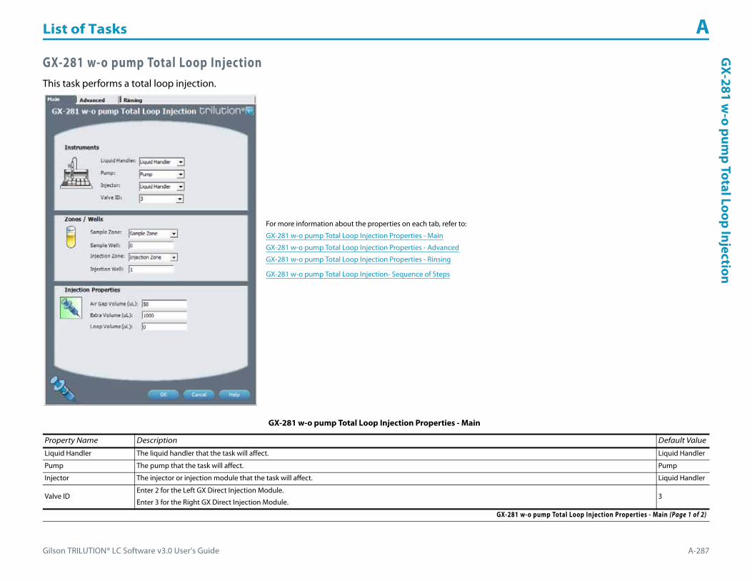
Gilson TRILUTION® LC Software v3.0 User’s Guide A-287
List of Tasks AG
X-281 w-o pum
p Total Loop Injection
GX-281 w-o pump Total Loop InjectionThis task performs a total loop injection.
For more information about the properties on each tab, refer to:
GX-281 w-o pump Total Loop Injection Properties - Main
GX-281 w-o pump Total Loop Injection Properties - Advanced
GX-281 w-o pump Total Loop Injection Properties - Rinsing
GX-281 w-o pump Total Loop Injection- Sequence of Steps
GX-281 w-o pump Total Loop Injection Properties - Main
Property Name Description Default Value
Liquid Handler The liquid handler that the task will affect. Liquid Handler
Pump The pump that the task will affect. Pump
Injector The injector or injection module that the task will affect. Liquid Handler
Valve IDEnter 2 for the Left GX Direct Injection Module.
Enter 3 for the Right GX Direct Injection Module.3
GX-281 w-o pump Total Loop Injection Properties - Main (Page 1 of 2)

List of Tasks A
A-288 Gilson TRILUTION® LC Software v3.0 User’s Guide
GX-
281
w-o
pum
p To
tal L
oop
Inje
ctio
n
Sample Zone The zone from which the Extra Volume and Loop Volume are aspirated. Sample Zone
Sample Well Enter the well number in the Sample Zone. 0
Injection Zone The zone to which the Extra Volume, and Loop Volume are dispensed. Injection Zone
Injection Well Enter the well number in the Injection Zone. 1
Air Gap Volume The quantity of an air gap. 50 μL
Extra Volume An additional volume to the first volume aspirated. It ensures that the actual volume of liquid to be transferred is not contaminated, and acts as an extra buffer between the air gap/reservoir solvent and the Loop Volume. 1000 μL
Loop Volume The capacity of the installed sample loop. 0 μL
GX-281 w-o pump Total Loop Injection Properties - Advanced
Property Name Description Default Value
Aspirate Flow Rate The speed at which liquid volumes move into the probe. 5 mL/min
Dispense Flow Rate The speed at which liquid volumes move out of the probe. 5 mL/min
Air Gap Flow Rate The speed at which the Air Gap Volume moves into the probe. 1 mL/min
Injection Equilibration Time The time the program waits after loading the Extra Volume and Loop Volume in the sample loop. 0.05 min
Sample Z Option
One of six defined reference points used when aspirating the Extra Volume and Loop Volume from the bed:
Auto Calculate: Places probe into well and at the liquid level using initial volume from the sample list and well dimensions from the bed layout; accepts a positive (+) or negative (-) value for the Sample Z Offset.
Absolute Value: Moves the probe to the Z-value entered; if 0 is entered, probe will move to the bed bottom (no safety factor incorporated).
Tube Bottom: Moves the probe to the well bottom as defined by the bed layout; accepts only positive Sample Z Offset value to move up from the bottom.
Top: Moves probe to the top of their Z-travel range; accepts only a negative (-) value for the Sample Z Offset.
Tube Top: Moves the probe to the top of the well as defined by the bed layout; accepts a positive (+) or negative (-) value for the Sample Z Offset.
Z Adjust: Moves the probe from the current position up (positive value) or down (negative value).
Tube Bottom
Sample Z Offset The distance up (when a positive number is entered) or down (when a negative number is entered) from a reference point defined by the Sample Z Option used when aspirating the Extra Volume and Loop Volume from the bed. 2 mm
Liquid Level FollowingWhen selected, the probe will follow the liquid down as it is aspirated from the Sample Zone. The Sample Z Option must be set to AUTO CALCULATE and initial volumes must be set in the sample list to use this option.
When cleared, the probe will not follow the liquid down as it is aspirated from the Sample Zone.Cleared
GX-281 w-o pump Total Loop Injection Properties - Advanced (Page 1 of 2)
GX-281 w-o pump Total Loop Injection Properties - Main (Continued)
Property Name Description Default Value
GX-281 w-o pump Total Loop Injection Properties - Main (Page 2 of 2)
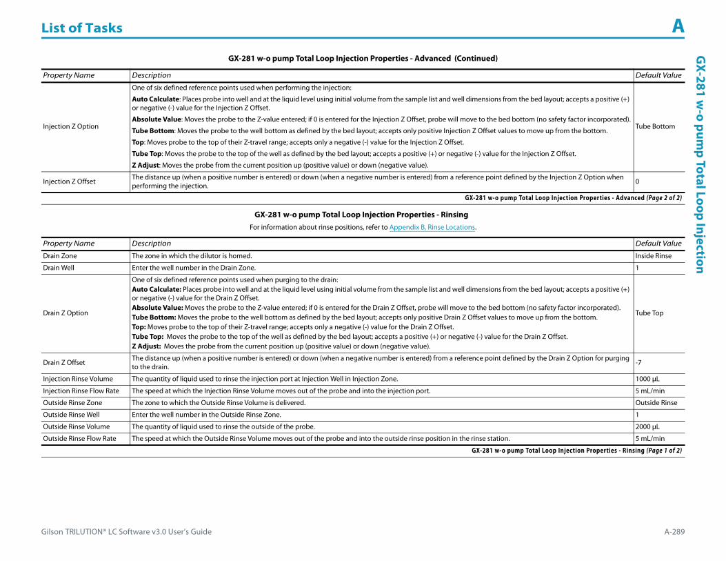
Gilson TRILUTION® LC Software v3.0 User’s Guide A-289
List of Tasks AG
X-281 w-o pum
p Total Loop Injection
Injection Z Option
One of six defined reference points used when performing the injection:
Auto Calculate: Places probe into well and at the liquid level using initial volume from the sample list and well dimensions from the bed layout; accepts a positive (+) or negative (-) value for the Injection Z Offset.
Absolute Value: Moves the probe to the Z-value entered; if 0 is entered for the Injection Z Offset, probe will move to the bed bottom (no safety factor incorporated).
Tube Bottom: Moves the probe to the well bottom as defined by the bed layout; accepts only positive Injection Z Offset values to move up from the bottom.
Top: Moves probe to the top of their Z-travel range; accepts only a negative (-) value for the Injection Z Offset.
Tube Top: Moves the probe to the top of the well as defined by the bed layout; accepts a positive (+) or negative (-) value for the Injection Z Offset.
Z Adjust: Moves the probe from the current position up (positive value) or down (negative value).
Tube Bottom
Injection Z Offset The distance up (when a positive number is entered) or down (when a negative number is entered) from a reference point defined by the Injection Z Option when performing the injection.
0
GX-281 w-o pump Total Loop Injection Properties - Rinsing For information about rinse positions, refer to Appendix B, Rinse Locations.
Property Name Description Default Value
Drain Zone The zone in which the dilutor is homed. Inside Rinse
Drain Well Enter the well number in the Drain Zone. 1
Drain Z Option
One of six defined reference points used when purging to the drain:Auto Calculate: Places probe into well and at the liquid level using initial volume from the sample list and well dimensions from the bed layout; accepts a positive (+) or negative (-) value for the Drain Z Offset.Absolute Value: Moves the probe to the Z-value entered; if 0 is entered for the Drain Z Offset, probe will move to the bed bottom (no safety factor incorporated).Tube Bottom: Moves the probe to the well bottom as defined by the bed layout; accepts only positive Drain Z Offset values to move up from the bottom.Top: Moves probe to the top of their Z-travel range; accepts only a negative (-) value for the Drain Z Offset.Tube Top: Moves the probe to the top of the well as defined by the bed layout; accepts a positive (+) or negative (-) value for the Drain Z Offset.Z Adjust: Moves the probe from the current position up (positive value) or down (negative value).
Tube Top
Drain Z Offset The distance up (when a positive number is entered) or down (when a negative number is entered) from a reference point defined by the Drain Z Option for purging to the drain. -7
Injection Rinse Volume The quantity of liquid used to rinse the injection port at Injection Well in Injection Zone. 1000 μL
Injection Rinse Flow Rate The speed at which the Injection Rinse Volume moves out of the probe and into the injection port. 5 mL/min
Outside Rinse Zone The zone to which the Outside Rinse Volume is delivered. Outside Rinse
Outside Rinse Well Enter the well number in the Outside Rinse Zone. 1
Outside Rinse Volume The quantity of liquid used to rinse the outside of the probe. 2000 μL
Outside Rinse Flow Rate The speed at which the Outside Rinse Volume moves out of the probe and into the outside rinse position in the rinse station. 5 mL/min
GX-281 w-o pump Total Loop Injection Properties - Rinsing (Page 1 of 2)
GX-281 w-o pump Total Loop Injection Properties - Advanced (Continued)
Property Name Description Default Value
GX-281 w-o pump Total Loop Injection Properties - Advanced (Page 2 of 2)

List of Tasks A
A-290 Gilson TRILUTION® LC Software v3.0 User’s Guide
GX-
281
w-o
pum
p To
tal L
oop
Inje
ctio
n
GX-281 w-o pump Total Loop Injection- Sequence of StepsThe following is an overview for the sequence of steps.
1 Initialize2 Aspirate3 Inject4 Injection Port Rinse5 Outside Rinse
Initialize1 Move Z to Z Safe Height.2 Set injection valve to INJECT.3 Move to Drain Well in Drain Zone.4 Lower probe into well to Drain Z Option and Drain Z Offset.5 Home dilutor.6 Move Z to Z Safe Height.
Outside Rinse Z Option
One of six defined reference points used when performing the outside rinse:Auto Calculate: Places probe into well and at the liquid level using initial volume from the sample list and well dimensions from the bed layout; accepts a positive (+) or negative (-) value for the Outside Rinse Z Offset.Absolute Value: Moves the probe to the Z-value entered; if 0 is entered for the Outside Rinse Z Offset, the probe will move to the bed bottom (no safety factor incorporated).Tube Bottom: Moves the probe to the well bottom as defined by the bed layout; accepts only positive Outside Rinse Z Offset values to move up from the bottom.Top: Moves probe to the top of their Z-travel range; accepts only a negative (-) value for the Outside Rinse Z Offset.Tube Top: Moves the probe to the top of the well as defined by the bed layout; accepts a positive (+) or negative (-) value for the Outside Rinse Z Offset.Z Adjust: Moves the probe from the current position up (positive value) or down (negative value).
Tube Bottom
Outside Rinse Z Offset The distance up (when a positive number is entered) or down (when a negative number is entered) from a reference point defined by the Outside Rinse Z Option for rinsing the probe at the outside rinse position in the rinse station.
2 mm
GX-281 w-o pump Total Loop Injection Properties - Rinsing (Continued)For information about rinse positions, refer to Appendix B, Rinse Locations.
Property Name Description Default Value
GX-281 w-o pump Total Loop Injection Properties - Rinsing (Page 2 of 2)

Gilson TRILUTION® LC Software v3.0 User’s Guide A-291
List of Tasks AG
X-281 w-o pum
p Total Loop Injection
Aspirate1 Aspirate Air Gap Volume at Air Gap Flow Rate.2 Move to Sample Well in Sample Zone.3 Lower probe into well to Sample Z Option and Sample Z Offset.4 Aspirate Loop Volume + Extra Volume at Aspirate Flow Rate.5 Move Z to Z Safe Height.
Inject1 Move to Injection Well in Injection Zone.2 Lower probe to Injection Z Option and Injection Z Offset.3 Switch injection valve to LOAD.4 Wait 1.2 sec.5 Dispense Loop Volume + 1/2 Extra Volume at Dispense Flow Rate.6 Wait Injection Equilibration Time.7 Synchronize.8 Switch injection valve to INJECT.
Injection Port Rinse1 Home dilutor.2 Aspirate Injection Rinse Volume or syringe capacity (from Reservoir) at Injection Rinse Flow Rate.3 Dispense Injection Rinse Volume or syringe capacity at Injection Rinse Flow Rate.4 Repeat steps 2–3 until requested rinse volume is aspirated and dispensed.5 Move Z to Z Safe Height.
Outside Rinse1 Move to Outside Rinse Well in Outside Rinse Zone.2 Lower probe into well to Outside Rinse Z Option and Outside Rinse Z Offset.3 Home dilutor.4 Aspirate Outside Rinse Volume or syringe capacity (from Reservoir) at Outside Rinse Flow Rate.5 Dispense Outside Rinse Volume or syringe capacity at Outside Rinse Flow Rate.6 Repeat steps 4–5 until requested rinse volume is aspirated and dispensed.7 Move Z to Safe Height.
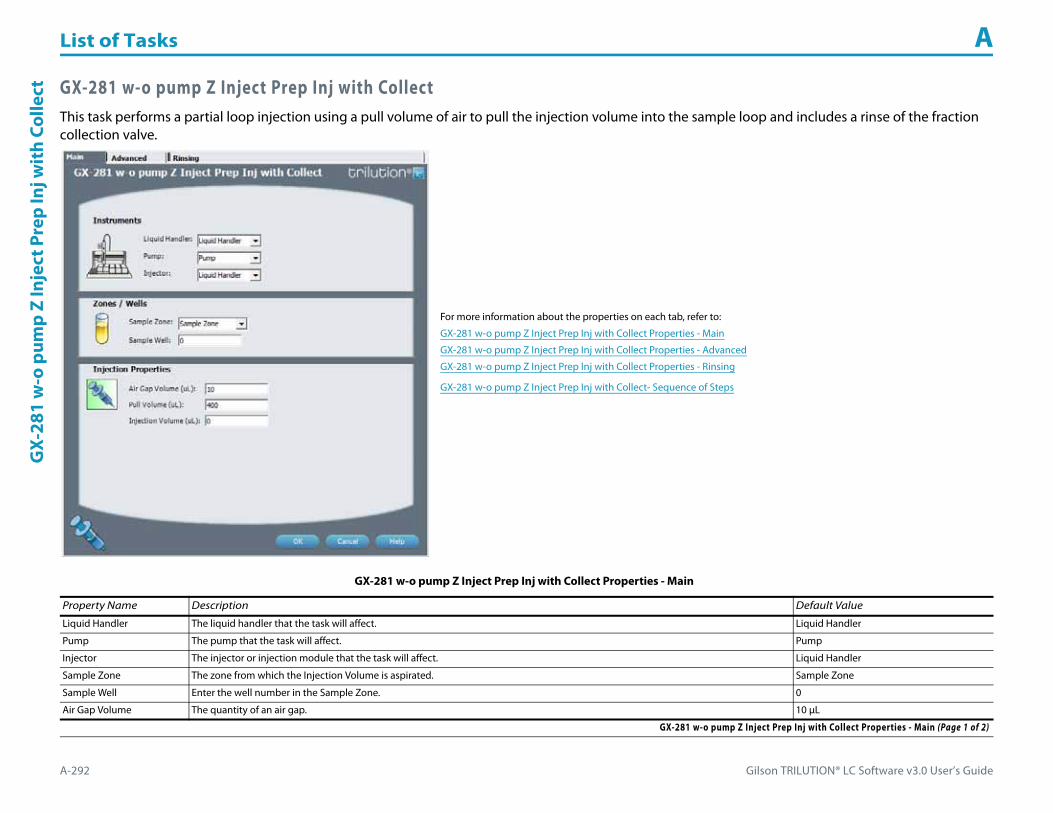
List of Tasks A
A-292 Gilson TRILUTION® LC Software v3.0 User’s Guide
GX-
281
w-o
pum
p Z
Inje
ct P
rep
Inj w
ith
Colle
ct GX-281 w-o pump Z Inject Prep Inj with CollectThis task performs a partial loop injection using a pull volume of air to pull the injection volume into the sample loop and includes a rinse of the fraction collection valve.
For more information about the properties on each tab, refer to:
GX-281 w-o pump Z Inject Prep Inj with Collect Properties - Main
GX-281 w-o pump Z Inject Prep Inj with Collect Properties - Advanced
GX-281 w-o pump Z Inject Prep Inj with Collect Properties - Rinsing
GX-281 w-o pump Z Inject Prep Inj with Collect- Sequence of Steps
GX-281 w-o pump Z Inject Prep Inj with Collect Properties - Main
Property Name Description Default Value
Liquid Handler The liquid handler that the task will affect. Liquid Handler
Pump The pump that the task will affect. Pump
Injector The injector or injection module that the task will affect. Liquid Handler
Sample Zone The zone from which the Injection Volume is aspirated. Sample Zone
Sample Well Enter the well number in the Sample Zone. 0
Air Gap Volume The quantity of an air gap. 10 μL
GX-281 w-o pump Z Inject Prep Inj with Collect Properties - Main (Page 1 of 2)

Gilson TRILUTION® LC Software v3.0 User’s Guide A-293
List of Tasks AG
X-281 w-o pum
p Z Inject Prep Inj with Collect
Pull Volume A volume of air used to pull the injection volume into the sample loop.
400 μL
Note: This default was determined using a 125 mm Z travel height, a 0.8 mm ID probe, and 35.6 cm (14 in.) of 0.8 mm ID tubing between the probe and the injection valve.
Injection Volume The volume of sample to be injected. 0 μL
GX-281 w-o pump Z Inject Prep Inj with Collect Properties - Advanced
Property Name Description Default Value
Aspirate Flow Rate The speed at which the Injection Volume and Pull Volume move into the probe. 2 mL/min
Air Gap Flow Rate The speed at which the Air Gap Volume moves into the probe. 1 mL/min
Injection Equilibration Time The time the program waits after loading the Injection Volume and Pull Volume in the sample loop. 0.05 min
Sample Z Option
One of six defined reference points used when aspirating the Injection Volume from the bed:
Auto Calculate: Places probe into well and at the liquid level using initial volume from the sample list and well dimensions from the bed layout; accepts a positive (+) or negative (-) value for the Sample Z Offset.
Absolute Value: Moves the probe to the Z-value entered; if 0 is entered, probe will move to the bed bottom (no safety factor incorporated).
Tube Bottom: Moves the probe to the well bottom as defined by the bed layout; accepts only positive Sample Z Offset value to move up from the bottom.
Top: Moves probe to the top of their Z-travel range; accepts only a negative (-) value for the Sample Z Offset.
Tube Top: Moves the probe to the top of the well as defined by the bed layout; accepts a positive (+) or negative (-) value for the Sample Z Offset.
Z Adjust: Moves the probe from the current position up (positive value) or down (negative value).
Tube Bottom
Sample Z Offset The distance up (when a positive number is entered) or down (when a negative number is entered) from a reference point defined by the Sample Z Option used when aspirating the Injection Volume from the bed. 2 mm
Liquid Level FollowingWhen selected, the probe will follow the liquid down as it is aspirated from the Sample Zone. The Sample Z Option must be set to AUTO CALCULATE and initial volumes must be set in the sample list to use this option.
When cleared, the probe will not follow the liquid down as it is aspirated from the Sample Zone.Cleared
GX-281 w-o pump Z Inject Prep Inj with Collect Properties - Advanced
GX-281 w-o pump Z Inject Prep Inj with Collect Properties - Rinsing For information about rinse positions, refer to Appendix B, Rinse Locations.
Property Name Description Default Value
Inside Rinse Zone The zone to which the Inside Rinse Volume is delivered. Inside Rinse
Inside Rinse Well Enter the well number in the Inside Rinse Zone. 1
Inside Rinse Volume The quantity of liquid used to rinse the inside of the probe. 1000 μL
Inside Rinse Flow Rate The speed at which the Inside Rinse Volume moves out of the probe and into the inside rinse position in the rinse station. 5 mL/min
GX-281 w-o pump Z Inject Prep Inj with Collect Properties - Rinsing (Page 1 of 2)
GX-281 w-o pump Z Inject Prep Inj with Collect Properties - Main (Continued)
Property Name Description Default Value
GX-281 w-o pump Z Inject Prep Inj with Collect Properties - Main (Page 2 of 2)
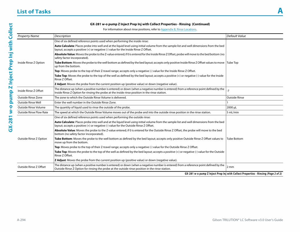
List of Tasks A
A-294 Gilson TRILUTION® LC Software v3.0 User’s Guide
GX-
281
w-o
pum
p Z
Inje
ct P
rep
Inj w
ith
Colle
ct
Inside Rinse Z Option
One of six defined reference points used when performing the inside rinse:
Auto Calculate: Places probe into well and at the liquid level using initial volume from the sample list and well dimensions from the bed layout; accepts a positive (+) or negative (-) value for the Inside Rinse Z Offset.
Absolute Value: Moves the probe to the Z-value entered; if 0 is entered for the Inside Rinse Z Offset, probe will move to the bed bottom (no safety factor incorporated).
Tube Bottom: Moves the probe to the well bottom as defined by the bed layout; accepts only positive Inside Rinse Z Offset values to move up from the bottom.
Top: Moves probe to the top of their Z-travel range; accepts only a negative (-) value for the Inside Rinse Z Offset.
Tube Top: Moves the probe to the top of the well as defined by the bed layout; accepts a positive (+) or negative (-) value for the Inside Rinse Z Offset.
Z Adjust: Moves the probe from the current position up (positive value) or down (negative value).
Tube Top
Inside Rinse Z Offset The distance up (when a positive number is entered) or down (when a negative number is entered) from a reference point defined by the Inside Rinse Z Option for rinsing the probe at the inside rinse position in the rinse station. -7
Outside Rinse Zone The zone to which the Outside Rinse Volume is delivered. Outside Rinse
Outside Rinse Well Enter the well number in the Outside Rinse Zone. 1
Outside Rinse Volume The quantity of liquid used to rinse the outside of the probe. 2000 μL
Outside Rinse Flow Rate The speed at which the Outside Rinse Volume moves out of the probe and into the outside rinse position in the rinse station. 5 mL/min
Outside Rinse Z Option
One of six defined reference points used when performing the outside rinse:
Auto Calculate: Places probe into well and at the liquid level using initial volume from the sample list and well dimensions from the bed layout; accepts a positive (+) or negative (-) value for the Outside Rinse Z Offset.
Absolute Value: Moves the probe to the Z-value entered; if 0 is entered for the Outside Rinse Z Offset, the probe will move to the bed bottom (no safety factor incorporated).
Tube Bottom: Moves the probe to the well bottom as defined by the bed layout; accepts only positive Outside Rinse Z Offset values to move up from the bottom.
Top: Moves probe to the top of their Z-travel range; accepts only a negative (-) value for the Outside Rinse Z Offset.
Tube Top: Moves the probe to the top of the well as defined by the bed layout; accepts a positive (+) or negative (-) value for the Outside Rinse Z Offset.
Z Adjust: Moves the probe from the current position up (positive value) or down (negative value).
Tube Bottom
Outside Rinse Z Offset The distance up (when a positive number is entered) or down (when a negative number is entered) from a reference point defined by the Outside Rinse Z Option for rinsing the probe at the outside rinse position in the rinse station. 2 mm
GX-281 w-o pump Z Inject Prep Inj with Collect Properties - Rinsing (Continued)For information about rinse positions, refer to Appendix B, Rinse Locations.
Property Name Description Default Value
GX-281 w-o pump Z Inject Prep Inj with Collect Properties - Rinsing (Page 2 of 2)

Gilson TRILUTION® LC Software v3.0 User’s Guide A-295
List of Tasks AG
X-281 w-o pum
p Z Inject Prep Inj with Collect
GX-281 w-o pump Z Inject Prep Inj with Collect- Sequence of StepsThe following is an overview for the sequence of steps.
1 Initialize2 Aspirate3 Inject4 Inside Rinse5 Outside Rinse
Initialize1 Move Z to Z Safe Height.2 Move to Inside Rinse Well in Inside Rinse Zone.3 Lower probe into well to Inside Rinse Z Option and Inside Rinse Z Offset.4 Home dilutor.5 Move Z to Z Safe Height.6 Switch fraction collection valve to COLLECT for 2 seconds.
Aspirate1 Switch injection valve to LOAD.2 Wait 0.02 min.3 Aspirate Air Gap Volume at Air Gap Flow Rate.4 Move to Sample Well in Sample Zone.5 Lower probe into well to Sample Z Option and Sample Z Offset.6 Aspirate Injection Volume at Aspirate Flow Rate.7 Move Z to Z Safe Height.8 Aspirate Pull Volume at Aspirate Flow Rate.9 Wait Injection Equilibration Time.10 Synchronize.
Inject1 Switch injection valve to INJECT.2 Move Z to Z Safe Height.

List of Tasks A
A-296 Gilson TRILUTION® LC Software v3.0 User’s Guide
GX-
281
w-o
pum
p Z
Inje
ct P
rep
Inj w
ith
Colle
ct Inside Rinse1 Move Z to Z Safe Height.2 Move to Inside Rinse Well in Inside Rinse Zone.3 Lower probe into well to Inside Rinse Z Option and Inside Rinse Z Offset.4 Home dilutor.5 Aspirate Inside Rinse Volume or syringe capacity (from Reservoir) at Inside Rinse Flow Rate.6 Dispense Inside Rinse Volume or syringe capacity at Inside Rinse Flow Rate.7 Repeat steps 5–6 until requested rinse volume is aspirated and dispensed.8 Move Z to Z Safe Height.
Outside Rinse1 Move to Outside Rinse Well in Outside Rinse Zone.2 Lower probe into well to Outside Rinse Z Option and Outside Rinse Z Offset.3 Home dilutor.4 Aspirate Outside Rinse Volume or syringe capacity (from Reservoir) at Outside Rinse Flow Rate.5 Dispense Outside Rinse Volume or syringe capacity at Outside Rinse Flow Rate.6 Repeat steps 4–5 until requested rinse volume is aspirated and dispensed.7 Move Z to Safe Height.
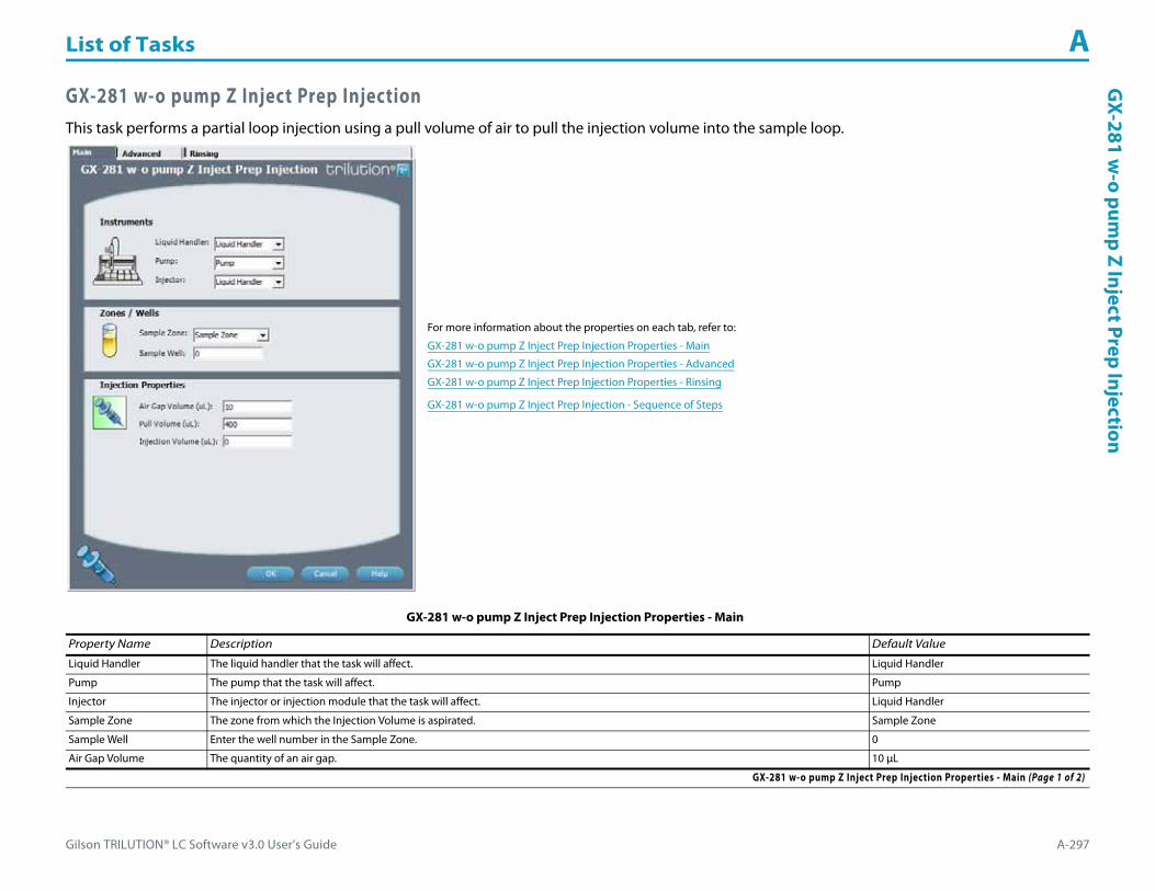
Gilson TRILUTION® LC Software v3.0 User’s Guide A-297
List of Tasks AG
X-281 w-o pum
p Z Inject Prep Injection
GX-281 w-o pump Z Inject Prep InjectionThis task performs a partial loop injection using a pull volume of air to pull the injection volume into the sample loop.
For more information about the properties on each tab, refer to:
GX-281 w-o pump Z Inject Prep Injection Properties - Main
GX-281 w-o pump Z Inject Prep Injection Properties - Advanced
GX-281 w-o pump Z Inject Prep Injection Properties - Rinsing
GX-281 w-o pump Z Inject Prep Injection - Sequence of Steps
GX-281 w-o pump Z Inject Prep Injection Properties - Main
Property Name Description Default Value
Liquid Handler The liquid handler that the task will affect. Liquid Handler
Pump The pump that the task will affect. Pump
Injector The injector or injection module that the task will affect. Liquid Handler
Sample Zone The zone from which the Injection Volume is aspirated. Sample Zone
Sample Well Enter the well number in the Sample Zone. 0
Air Gap Volume The quantity of an air gap. 10 μL
GX-281 w-o pump Z Inject Prep Injection Properties - Main (Page 1 of 2)

List of Tasks A
A-298 Gilson TRILUTION® LC Software v3.0 User’s Guide
GX-
281
w-o
pum
p Z
Inje
ct P
rep
Inje
ctio
n
Pull Volume A volume of air used to pull the injection volume into the sample loop.
400 μL
Note: This default was determined using a 125 mm Z travel height, a 0.8 mm ID probe, and 35.6 cm (14 in.) of 0.8 mm ID tubing between the probe and the injection valve.
Injection Volume The volume of sample to be injected. 0 μL
GX-281 w-o pump Z Inject Prep Injection Properties - Advanced
Property Name Description Default Value
Aspirate Flow Rate The speed at which the Injection Volume and Pull Volume move into the probe. 2 mL/min
Air Gap Flow Rate The speed at which the Air Gap Volume moves into the probe. 1 mL/min
Injection Equilibration Time The time the program waits after loading the Injection Volume and Pull Volume in the sample loop. 0.05 min
Sample Z Option
One of six defined reference points used when aspirating the Injection Volume from the bed:
Auto Calculate: Places probe into well and at the liquid level using initial volume from the sample list and well dimensions from the bed layout; accepts a positive (+) or negative (-) value for the Sample Z Offset.
Absolute Value: Moves the probe to the Z-value entered; if 0 is entered, probe will move to the bed bottom (no safety factor incorporated).
Tube Bottom: Moves the probe to the well bottom as defined by the bed layout; accepts only positive Sample Z Offset value to move up from the bottom.
Top: Moves probe to the top of their Z-travel range; accepts only a negative (-) value for the Sample Z Offset.
Tube Top: Moves the probe to the top of the well as defined by the bed layout; accepts a positive (+) or negative (-) value for the Sample Z Offset.
Z Adjust: Moves the probe from the current position up (positive value) or down (negative value).
Tube Bottom
Sample Z Offset The distance up (when a positive number is entered) or down (when a negative number is entered) from a reference point defined by the Sample Z Option used when aspirating the Injection Volume from the bed. 2 mm
Liquid Level FollowingWhen selected, the probe will follow the liquid down as it is aspirated from the Sample Zone. The Sample Z Option must be set to AUTO CALCULATE and initial volumes must be set in the sample list to use this option.
When cleared, the probe will not follow the liquid down as it is aspirated from the Sample Zone.Cleared
GX-281 w-o pump Z Inject Prep Injection Properties - Advanced
GX-281 w-o pump Z Inject Prep Injection Properties - Rinsing For information about rinse positions, refer to Appendix B, Rinse Locations.
Property Name Description Default Value
Inside Rinse Zone The zone to which the Inside Rinse Volume is delivered. Inside Rinse
Inside Rinse Well Enter the well number in the Inside Rinse Zone. 1
Inside Rinse Volume The quantity of liquid used to rinse the inside of the probe. 1000 μL
Inside Rinse Flow Rate The speed at which the Inside Rinse Volume moves out of the probe and into the inside rinse position in the rinse station. 5 mL/min
GX-281 w-o pump Z Inject Prep Injection Properties - Rinsing (Page 1 of 2)
GX-281 w-o pump Z Inject Prep Injection Properties - Main (Continued)
Property Name Description Default Value
GX-281 w-o pump Z Inject Prep Injection Properties - Main (Page 2 of 2)
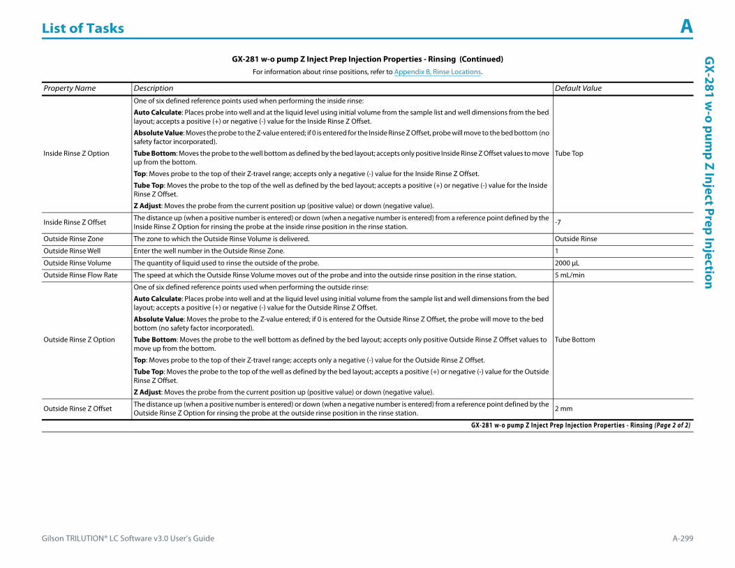
Gilson TRILUTION® LC Software v3.0 User’s Guide A-299
List of Tasks AG
X-281 w-o pum
p Z Inject Prep Injection
Inside Rinse Z Option
One of six defined reference points used when performing the inside rinse:
Auto Calculate: Places probe into well and at the liquid level using initial volume from the sample list and well dimensions from the bed layout; accepts a positive (+) or negative (-) value for the Inside Rinse Z Offset.
Absolute Value: Moves the probe to the Z-value entered; if 0 is entered for the Inside Rinse Z Offset, probe will move to the bed bottom (no safety factor incorporated).
Tube Bottom: Moves the probe to the well bottom as defined by the bed layout; accepts only positive Inside Rinse Z Offset values to move up from the bottom.
Top: Moves probe to the top of their Z-travel range; accepts only a negative (-) value for the Inside Rinse Z Offset.
Tube Top: Moves the probe to the top of the well as defined by the bed layout; accepts a positive (+) or negative (-) value for the Inside Rinse Z Offset.
Z Adjust: Moves the probe from the current position up (positive value) or down (negative value).
Tube Top
Inside Rinse Z Offset The distance up (when a positive number is entered) or down (when a negative number is entered) from a reference point defined by the Inside Rinse Z Option for rinsing the probe at the inside rinse position in the rinse station. -7
Outside Rinse Zone The zone to which the Outside Rinse Volume is delivered. Outside Rinse
Outside Rinse Well Enter the well number in the Outside Rinse Zone. 1
Outside Rinse Volume The quantity of liquid used to rinse the outside of the probe. 2000 μL
Outside Rinse Flow Rate The speed at which the Outside Rinse Volume moves out of the probe and into the outside rinse position in the rinse station. 5 mL/min
Outside Rinse Z Option
One of six defined reference points used when performing the outside rinse:
Auto Calculate: Places probe into well and at the liquid level using initial volume from the sample list and well dimensions from the bed layout; accepts a positive (+) or negative (-) value for the Outside Rinse Z Offset.
Absolute Value: Moves the probe to the Z-value entered; if 0 is entered for the Outside Rinse Z Offset, the probe will move to the bed bottom (no safety factor incorporated).
Tube Bottom: Moves the probe to the well bottom as defined by the bed layout; accepts only positive Outside Rinse Z Offset values to move up from the bottom.
Top: Moves probe to the top of their Z-travel range; accepts only a negative (-) value for the Outside Rinse Z Offset.
Tube Top: Moves the probe to the top of the well as defined by the bed layout; accepts a positive (+) or negative (-) value for the Outside Rinse Z Offset.
Z Adjust: Moves the probe from the current position up (positive value) or down (negative value).
Tube Bottom
Outside Rinse Z Offset The distance up (when a positive number is entered) or down (when a negative number is entered) from a reference point defined by the Outside Rinse Z Option for rinsing the probe at the outside rinse position in the rinse station. 2 mm
GX-281 w-o pump Z Inject Prep Injection Properties - Rinsing (Continued)For information about rinse positions, refer to Appendix B, Rinse Locations.
Property Name Description Default Value
GX-281 w-o pump Z Inject Prep Injection Properties - Rinsing (Page 2 of 2)
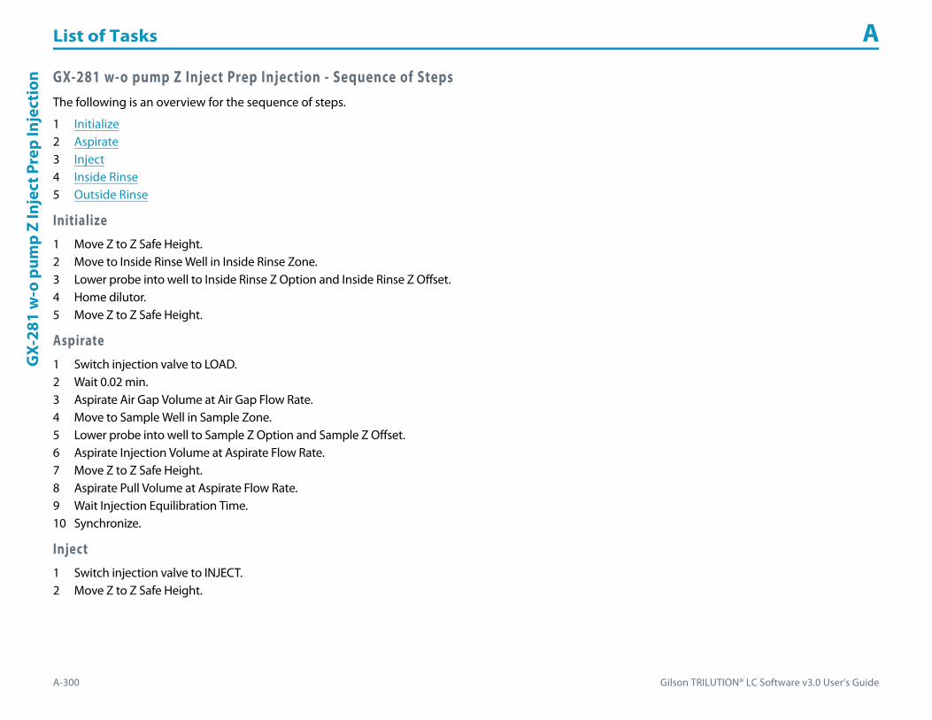
List of Tasks A
A-300 Gilson TRILUTION® LC Software v3.0 User’s Guide
GX-
281
w-o
pum
p Z
Inje
ct P
rep
Inje
ctio
n GX-281 w-o pump Z Inject Prep Injection - Sequence of StepsThe following is an overview for the sequence of steps.
1 Initialize2 Aspirate3 Inject4 Inside Rinse5 Outside Rinse
Initialize1 Move Z to Z Safe Height.2 Move to Inside Rinse Well in Inside Rinse Zone.3 Lower probe into well to Inside Rinse Z Option and Inside Rinse Z Offset.4 Home dilutor.5 Move Z to Z Safe Height.
Aspirate1 Switch injection valve to LOAD.2 Wait 0.02 min.3 Aspirate Air Gap Volume at Air Gap Flow Rate.4 Move to Sample Well in Sample Zone.5 Lower probe into well to Sample Z Option and Sample Z Offset.6 Aspirate Injection Volume at Aspirate Flow Rate.7 Move Z to Z Safe Height.8 Aspirate Pull Volume at Aspirate Flow Rate.9 Wait Injection Equilibration Time.10 Synchronize.
Inject1 Switch injection valve to INJECT.2 Move Z to Z Safe Height.

Gilson TRILUTION® LC Software v3.0 User’s Guide A-301
List of Tasks AG
X-281 w-o pum
p Z Inject Prep Injection
Inside Rinse1 Move Z to Z Safe Height.2 Move to Inside Rinse Well in Inside Rinse Zone.3 Lower probe into well to Inside Rinse Z Option and Inside Rinse Z Offset.4 Home dilutor.5 Aspirate Inside Rinse Volume or syringe capacity (from Reservoir) at Inside Rinse Flow Rate.6 Dispense Inside Rinse Volume or syringe capacity at Inside Rinse Flow Rate.7 Repeat steps 5–6 until requested rinse volume is aspirated and dispensed.8 Move Z to Z Safe Height.
Outside Rinse1 Move to Outside Rinse Well in Outside Rinse Zone.2 Lower probe into well to Outside Rinse Z Option and Outside Rinse Z Offset.3 Home dilutor.4 Aspirate Outside Rinse Volume or syringe capacity (from Reservoir) at Outside Rinse Flow Rate.5 Dispense Outside Rinse Volume or syringe capacity at Outside Rinse Flow Rate.6 Repeat steps 4–5 until requested rinse volume is aspirated and dispensed.7 Move Z to Safe Height.

List of Tasks A
A-302 Gilson TRILUTION® LC Software v3.0 User’s Guide
GX-
281
Z In
ject
Pre
p In
ject
ion GX-281 Z Inject Prep Injection
This task performs a partial loop injection using a pull volume of air to pull the injection volume into the sample loop.
For more information about the properties on each tab, refer to:
GX-281 Z Inject Prep Injection Properties - Main
GX-281 Z Inject Prep Injection Properties - Rinsing
GX-281 Z Inject Prep Injection - Sequence of Steps
GX-281 Z Inject Prep Injection Properties - Main
Property Name Description Default Value
Liquid Handler The liquid handler that the task will affect. Liquid Handler
Pump The pump that the task will affect. Liquid Handler
Injector The injector or injection module that the task will affect. Liquid Handler
Solvent Valve PositionThe desired position of the solvent selection valve on the GX Solvent System. Valid range is 1–6.
The position designated for waste cannot be used for a solvent.2
Sample Zone The zone from which the Injection Volume is aspirated. Sample Zone
GX-281 Z Inject Prep Injection Properties - Main (Page 1 of 2)
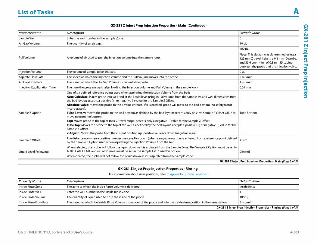
Gilson TRILUTION® LC Software v3.0 User’s Guide A-303
List of Tasks AG
X-281 Z Inject Prep Injection
Sample Well Enter the well number in the Sample Zone. 0
Air Gap Volume The quantity of an air gap. 10 μL
Pull Volume A volume of air used to pull the injection volume into the sample loop.
400 μL
Note: This default was determined using a 125 mm Z travel height, a 0.8 mm ID probe, and 35.6 cm (14 in.) of 0.8 mm ID tubing between the probe and the injection valve.
Injection Volume The volume of sample to be injected. 0 μL
Aspirate Flow Rate The speed at which the Injection Volume and the Pull Volume moves into the probe. 2 mL/min
Air Gap Flow Rate The speed at which the Air Gap Volume moves into the probe. 1 mL/min
Injection Equilibration Time The time the program waits after loading the Injection Volume and Pull Volume in the sample loop. 0.05 min
Sample Z Option
One of six defined reference points used when aspirating the Injection Volume from the bed:Auto Calculate: Places probe into well and at the liquid level using initial volume from the sample list and well dimensions from the bed layout; accepts a positive (+) or negative (-) value for the Sample Z Offset.Absolute Value: Moves the probe to the Z-value entered; if 0 is entered, probe will move to the bed bottom (no safety factor incorporated).Tube Bottom: Moves the probe to the well bottom as defined by the bed layout; accepts only positive Sample Z Offset value to move up from the bottom.Top: Moves probe to the top of their Z-travel range; accepts only a negative (-) value for the Sample Z Offset.Tube Top: Moves the probe to the top of the well as defined by the bed layout; accepts a positive (+) or negative (-) value for the Sample Z Offset.Z Adjust: Moves the probe from the current position up (positive value) or down (negative value).
Tube Bottom
Sample Z Offset The distance up (when a positive number is entered) or down (when a negative number is entered) from a reference point defined by the Sample Z Option used when aspirating the Injection Volume from the bed. 2 mm
Liquid Level FollowingWhen selected, the probe will follow the liquid down as it is aspirated from the Sample Zone. The Sample Z Option must be set to AUTO CALCULATE and initial volumes must be set in the sample list to use this option.
When cleared, the probe will not follow the liquid down as it is aspirated from the Sample Zone.Cleared
GX-281 Z Inject Prep Injection Properties - Rinsing For information about rinse positions, refer to Appendix B, Rinse Locations.
Property Name Description Default Value
Inside Rinse Zone The zone to which the Inside Rinse Volume is delivered. Inside Rinse
Inside Rinse Well Enter the well number in the Inside Rinse Zone. 1
Inside Rinse Volume The quantity of liquid used to rinse the inside of the probe. 1000 μL
Inside Rinse Flow Rate The speed at which the Inside Rinse Volume moves out of the probe and into the inside rinse position in the rinse station. 5 mL/min
GX-281 Z Inject Prep Injection Properties - Rinsing (Page 1 of 3)
GX-281 Z Inject Prep Injection Properties - Main (Continued)
Property Name Description Default Value
GX-281 Z Inject Prep Injection Properties - Main (Page 2 of 2)

List of Tasks A
A-304 Gilson TRILUTION® LC Software v3.0 User’s Guide
GX-
281
Z In
ject
Pre
p In
ject
ion
Inside Rinse Z Option
One of six defined reference points used when performing the inside rinse:Auto Calculate: Places probe into well and at the liquid level using initial volume from the sample list and well dimensions from the bed layout; accepts a positive (+) or negative (-) value for the Inside Rinse Z Offset.Absolute Value: Moves the probe to the Z-value entered; if 0 is entered for the Inside Rinse Z Offset, the probe will move to the bed bottom (no safety factor incorporated).Tube Bottom: Moves the probe to the well bottom as defined by the bed layout; accepts only positive Inside Rinse Z Offset values to move up from the bottom.Top: Moves probe to the top of their Z-travel range; accepts only a negative (-) value for the Inside Rinse Z Offset.Tube Top: Moves the probe to the top of the well as defined by the bed layout; accepts a positive (+) or negative (-) value for the Inside Rinse Z Offset.Z Adjust: Moves the probe from the current position up (positive value) or down (negative value).
Tube Top
Inside Rinse Z Offset The distance up (when a positive number is entered) or down (when a negative number is entered) from a reference point defined by the Inside Rinse Z Option for rinsing the probe at the inside rinse position in the rinse station. -7 mm
Outside Rinse Zone The zone to which the Outside Rinse Volume is delivered. Outside Rinse
Number of Rinse Stations Select the number of rinse stations to be used when performing the outside rinse. Valid range is 1–5. 1
Rinse Well 1 Solvent Valve PositionThe desired position of the solvent selection valve on the GX Solvent System during the outside rinse at rinse station 1. Valid range is 1–6.
The position designated for waste cannot be used for a solvent.2
Rinse Well 2 Solvent Valve PositionThe desired position of the solvent selection valve on the GX Solvent System during the outside rinse at rinse station 2. Valid range is 1–6.
The position designated for waste cannot be used for a solvent.2
Rinse Well 3 Solvent Valve PositionThe desired position of the solvent selection valve on the GX Solvent System during the outside rinse at rinse station 3. Valid range is 1–6.
The position designated for waste cannot be used for a solvent.2
Rinse Well 4 Solvent Valve PositionThe desired position of the solvent selection valve on the GX Solvent System during the outside rinse at rinse station 4. Valid range is 1–6.
The position designated for waste cannot be used for a solvent.2
Rinse Well 5 Solvent Valve PositionThe desired position of the solvent selection valve on the GX Solvent System during the outside rinse at rinse station 5. Valid range is 1–6.
The position designated for waste cannot be used for a solvent.2
Outside Rinse Volume The quantity of liquid used to rinse the outside of the probe. 2000 μL
Outside Rinse Flow Rate The speed at which the Outside Rinse Volume moves out of the probe and into the outside rinse position in the rinse station. 5 mL/min
GX-281 Z Inject Prep Injection Properties - Rinsing (Continued)For information about rinse positions, refer to Appendix B, Rinse Locations.
Property Name Description Default Value
GX-281 Z Inject Prep Injection Properties - Rinsing (Page 2 of 3)

Gilson TRILUTION® LC Software v3.0 User’s Guide A-305
List of Tasks AG
X-281 Z Inject Prep Injection
Outside Rinse Z Option
One of six defined reference points used when performing the outside rinse:Auto Calculate: Places probe into well and at the liquid level using initial volume from the sample list and well dimensions from the bed layout; accepts a positive (+) or negative (-) value for the Outside Rinse Z Offset.Absolute Value: Moves the probe to the Z-value entered; if 0 is entered for the Outside Rinse Z Offset, the probe will move to the bed bottom (no safety factor incorporated).Tube Bottom: Moves the probe to the well bottom as defined by the bed layout; accepts only positive Outside Rinse Z Offset values to move up from the bottom.Top: Moves probe to the top of their Z-travel range; accepts only a negative (-) value for the Outside Rinse Z Offset.Tube Top: Moves the probe to the top of the well as defined by the bed layout; accepts a positive (+) or negative (-) value for the Outside Rinse Z Offset.Z Adjust: Moves the probe from the current position up (positive value) or down (negative value).
Tube Bottom
Outside Rinse Z Offset The distance up (when a positive number is entered) or down (when a negative number is entered) from a reference point defined by the Outside Rinse Z Option for rinsing the probe at the outside rinse position in the rinse station. 2 mm
Rinse Pump The rinse pump that will be used for the flowing outside rinse. Select 1 if the rinse pump is wired to Output 1 and 24V Output 1 or select 2 if the rinse pump is wired to Output 2 and 24V Output 2. 1
Rinse Pump Speed Select HIGH, LOW, or OFF. OFF
GX-281 Z Inject Prep Injection Properties - Rinsing (Continued)For information about rinse positions, refer to Appendix B, Rinse Locations.
Property Name Description Default Value
GX-281 Z Inject Prep Injection Properties - Rinsing (Page 3 of 3)

List of Tasks A
A-306 Gilson TRILUTION® LC Software v3.0 User’s Guide
GX-
281
Z In
ject
Pre
p In
ject
ion GX-281 Z Inject Prep Injection - Sequence of Steps
The following is an overview for the sequence of steps.
1 Initialize2 Aspirate3 Inject4 Inside Rinse5 Outside Rinse
Initialize1 Move Z to Z Safe Height.2 Move to Inside Rinse Well in Inside Rinse Zone.3 Lower probe into well to Inside Rinse Z Option and Inside Rinse Z Offset.4 Switch solvent valve to Solvent Valve Position and dispense volume held by transfer tubing at 5 mL/min.5 Move Z to Z Safe Height.
Aspirate1 Switch injection valve to LOAD.2 Wait 0.02 min.3 Switch solvent valve to waste and aspirate Air Gap Volume at Air Gap Flow Rate.4 Move to Sample Well in Sample Zone.5 Lower probe into well to Sample Z Option and Sample Z Offset.6 Aspirate Injection Volume at Aspirate Flow Rate.7 Move Z to Z Safe Height.8 Aspirate Pull Volume at Aspirate Flow Rate.9 Wait injection equilibration time.10 Synchronize.
Inject1 Switch injection valve to INJECT.2 Move Z to Z Safe Height.

Gilson TRILUTION® LC Software v3.0 User’s Guide A-307
List of Tasks AG
X-281 Z Inject Prep Injection
Inside Rinse1 Move Z to Z Safe Height.2 Move to Inside Rinse Well in Inside Rinse Zone.3 Lower probe into well to Inside Rinse Z Option and Inside Rinse Z Offset.4 Switch solvent valve to Solvent Valve Position and dispense volume held by transfer tubing at Inside Rinse Flow Rate.5 Dispense Inside Rinse Volume at Inside Rinse Flow Rate.6 Move Z to Z Safe Height.
Outside Rinse1 Move Z to Z Safe Height.2 Move to rinse station/well 1 in Outside Rinse Zone.3 Lower probe into well to Outside Rinse Z Option and Outside Rinse Z Offset.4 Switch Rinse Pump on at Rinse Pump Speed.5 Switch solvent valve to Rinse Well 1 Solvent Valve Position and dispense Outside Rinse Volume at Outside Rinse Flow Rate. If the current solvent valve position
is not the same as the previous solvent valve position, dispense Outside Rinse Volume + 2000 uL + Transfer Tubing volume.6 Switch Rinse Pump off.7 Move Z to Z Safe Height.8 Repeat steps 2–7 for the Number of Rinse Stations, incrementing the rinse station/well for each rinse station.

List of Tasks A
A-308 Gilson TRILUTION® LC Software v3.0 User’s Guide
GX-
281
Z In
ject
Pre
p In
ject
ion
wit
h Co
llect
ion GX-281 Z Inject Prep Injection with Collection
This task performs a partial loop injection using a pull volume of air to pull the injection volume into the sample loop and includes a rinse of the fraction collection valve.
For more information about the properties on each tab, refer to:
GX-281 Z Inject Prep Injection with Collection Properties - Main
GX-281 Z Inject Prep Injection with Collection Properties - Rinsing
GX-281 Z Inject Prep Injection with Collection - Sequence of Steps
GX-281 Z Inject Prep Injection with Collection Properties - Main
Property Name Description Default Value
Liquid Handler The liquid handler that the task will affect. Liquid Handler
Pump The pump that the task will affect. Liquid Handler
Injector The injector or injection module that the task will affect. Liquid Handler
Solvent Valve PositionThe desired position of the solvent selection valve on the GX Solvent System. Valid range is 1–6.
The position designated for waste cannot be used for a solvent.2
GX-281 Z Inject Prep Injection with Collection Properties - Main (Page 1 of 2)

Gilson TRILUTION® LC Software v3.0 User’s Guide A-309
List of Tasks AG
X-281 Z Inject Prep Injection with Collection
Sample Zone The zone from which the Injection Volume is aspirated. Sample Zone
Sample Well Enter the well number in the Sample Zone. 0
Air Gap Volume The quantity of an air gap. 10 μL
Pull Volume A volume of air used to pull the injection volume into the sample loop.
400 μL
Note: This default was determined using a 125 mm Z travel height, a 0.8 mm ID probe, and 35.6 cm (14 in.) of 0.8 mm ID tubing between the probe and the injection valve.
Injection Volume The volume of sample to be injected. 0 μL
Aspirate Flow Rate The speed at which the Injection Volume and the Pull Volume moves into the probe. 2 mL/min
Air Gap Flow Rate The speed at which the Air Gap Volume moves into the probe. 1 mL/min
Injection Equilibration Time The time the program waits after loading the Injection Volume and Pull Volume in the sample loop. 0.05 min
Sample Z Option
One of six defined reference points used when aspirating the Injection Volume from the bed:Auto Calculate: Places probe into well and at the liquid level using initial volume from the sample list and well dimensions from the bed layout; accepts a positive (+) or negative (-) value for the Sample Z Offset.Absolute Value: Moves the probe to the Z-value entered; if 0 is entered for the Sample Z Offset, the probe will move to the bed bottom (no safety factor incorporated).Tube Bottom: Moves the probe to the well bottom as defined by the bed layout; accepts only positive Sample Z Offset value to move up from the bottom.Top: Moves probe to the top of their Z-travel range; accepts only a negative (-) value for the Sample Z Offset.Tube Top: Moves the probe to the top of the well as defined by the bed layout; accepts a positive (+) or negative (-) value for the Sample Z Offset.Z Adjust: Moves the probe from the current position up (positive value) or down (negative value).
Tube Bottom
Sample Z Offset The distance up (when a positive number is entered) or down (when a negative number is entered) from a reference point defined by the Sample Z Option used when aspirating the Injection Volume from the bed. 2 mm
Liquid Level FollowingWhen selected, the probe will follow the liquid down as it is aspirated from the Sample Zone. The Sample Z Option must be set to AUTO CALCULATE and initial volumes must be set in the sample list to use this option.
When cleared, the probe will not follow the liquid down as it is aspirated from the Sample Zone.Cleared
GX-281 Z Inject Prep Injection with Collection Properties - Rinsing For information about rinse positions, refer to Appendix B, Rinse Locations.
Property Name Description Default Value
Inside Rinse Zone The zone to which the Inside Rinse Volume is delivered. Inside Rinse
Inside Rinse Well Enter the well number in the Inside Rinse Zone. 1
Inside Rinse Volume The quantity of liquid used to rinse the inside of the probe. 1000 μL
Inside Rinse Flow Rate The speed at which the Inside Rinse Volume moves out of the probe and into the inside rinse position in the rinse station. 5 mL/min
GX-281 Z Inject Prep Injection with Collection Properties - Rinsing (Page 1 of 3)
GX-281 Z Inject Prep Injection with Collection Properties - Main (Continued)
Property Name Description Default Value
GX-281 Z Inject Prep Injection with Collection Properties - Main (Page 2 of 2)

List of Tasks A
A-310 Gilson TRILUTION® LC Software v3.0 User’s Guide
GX-
281
Z In
ject
Pre
p In
ject
ion
wit
h Co
llect
ion
Inside Rinse Z Option
One of six defined reference points used when performing the inside rinse:Auto Calculate: Places probe into well and at the liquid level using initial volume from the sample list and well dimensions from the bed layout; accepts a positive (+) or negative (-) value for the Inside Rinse Z Offset.Absolute Value: Moves the probe to the Z-value entered; if 0 is entered for the Inside Rinse Z Offset, the probe will move to the bed bottom (no safety factor incorporated).Tube Bottom: Moves the probe to the well bottom as defined by the bed layout; accepts only positive Inside Rinse Z Offset values to move up from the bottom.Top: Moves probe to the top of their Z-travel range; accepts only a negative (-) value for the Inside Rinse Z Offset.Tube Top: Moves the probe to the top of the well as defined by the bed layout; accepts a positive (+) or negative (-) value for the Inside Rinse Z Offset.Z Adjust: Moves the probe from the current position up (positive value) or down (negative value).
Tube Top
Inside Rinse Z Offset The distance up (when a positive number is entered) or down (when a negative number is entered) from a reference point defined by the Inside Rinse Z Option for rinsing the probe at the inside rinse position in the rinse station. -7 mm
Outside Rinse Zone The zone to which the Outside Rinse Volume is delivered. Outside Rinse
Number of Rinse Stations Select the number of rinse stations to be used when performing the outside rinse. Valid range is 1–5. 1
Rinse Well 1 Solvent Valve Position
The desired position of the solvent selection valve on the GX Solvent System during the outside rinse at rinse station 1.
Valid range is 1–6.
The position designated for waste cannot be used for a solvent.
2
Rinse Well 2 Solvent Valve Position
The desired position of the solvent selection valve on the GX Solvent System during the outside rinse at rinse station 2.
Valid range is 1–6.
The position designated for waste cannot be used for a solvent.
2
Rinse Well 3 Solvent Valve Position
The desired position of the solvent selection valve on the GX Solvent System during the outside rinse at rinse station 3.
Valid range is 1–6.
The position designated for waste cannot be used for a solvent.
2
Rinse Well 4 Solvent Valve Position
The desired position of the solvent selection valve on the GX Solvent System during the outside rinse at rinse station 4.
Valid range is 1–6.
The position designated for waste cannot be used for a solvent.
2
Rinse Well 5 Solvent Valve Position
The desired position of the solvent selection valve on the GX Solvent System during the outside rinse at rinse station 5.
Valid range is 1–6.
The position designated for waste cannot be used for a solvent.
2
Outside Rinse Volume The quantity of liquid used to rinse the outside of the probe. 2000 μL
Outside Rinse Flow Rate The speed at which the Outside Rinse Volume moves out of the probe and into the outside rinse position in the rinse station. 5 mL/min
GX-281 Z Inject Prep Injection with Collection Properties - Rinsing (Continued)For information about rinse positions, refer to Appendix B, Rinse Locations.
Property Name Description Default Value
GX-281 Z Inject Prep Injection with Collection Properties - Rinsing (Page 2 of 3)
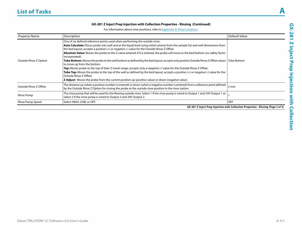
Gilson TRILUTION® LC Software v3.0 User’s Guide A-311
List of Tasks AG
X-281 Z Inject Prep Injection with Collection
Outside Rinse Z Option
One of six defined reference points used when performing the outside rinse:Auto Calculate: Places probe into well and at the liquid level using initial volume from the sample list and well dimensions from the bed layout; accepts a positive (+) or negative (-) value for the Outside Rinse Z Offset.Absolute Value: Moves the probe to the Z-value entered; if 0 is entered, the probe will move to the bed bottom (no safety factor incorporated).Tube Bottom: Moves the probe to the well bottom as defined by the bed layout; accepts only positive Outside Rinse Z Offset values to move up from the bottom.Top: Moves probe to the top of their Z-travel range; accepts only a negative (-) value for the Outside Rinse Z Offset.Tube Top: Moves the probe to the top of the well as defined by the bed layout; accepts a positive (+) or negative (-) value for the Outside Rinse Z Offset.Z Adjust: Moves the probe from the current position up (positive value) or down (negative value).
Tube Bottom
Outside Rinse Z Offset The distance up (when a positive number is entered) or down (when a negative number is entered) from a reference point defined by the Outside Rinse Z Option for rinsing the probe at the outside rinse position in the rinse station. 2 mm
Rinse Pump The rinse pump that will be used for the flowing outside rinse. Select 1 if the rinse pump is wired to Output 1 and 24V Output 1 or select 2 if the rinse pump is wired to Output 2 and 24V Output 2. 1
Rinse Pump Speed Select HIGH, LOW, or OFF. OFF
GX-281 Z Inject Prep Injection with Collection Properties - Rinsing (Continued)For information about rinse positions, refer to Appendix B, Rinse Locations.
Property Name Description Default Value
GX-281 Z Inject Prep Injection with Collection Properties - Rinsing (Page 3 of 3)

List of Tasks A
A-312 Gilson TRILUTION® LC Software v3.0 User’s Guide
GX-
281
Z In
ject
Pre
p In
ject
ion
wit
h Co
llect
ion GX-281 Z Inject Prep Injection with Collection - Sequence of Steps
The following is an overview for the sequence of steps.
1 Initialize2 Aspirate3 Inject4 Inside Rinse5 Outside Rinse
Initialize1 Move Z to Z Safe Height.2 Move to Inside Rinse Well in Inside Rinse Zone.3 Lower probe into well to Inside Rinse Z Option and Inside Rinse Z Offset.4 Switch solvent valve to Solvent Valve Position and dispense volume held by transfer tubing at 5 mL/min.5 Move Z to Z Safe Height.6 Switch fraction collection valve to COLLECT for 2 seconds.
Aspirate1 Switch injection valve to LOAD.2 Wait 0.02 min.3 Switch solvent valve to waste and aspirate Air Gap Volume at Air Gap Flow Rate.4 Move to Sample Well in Sample Zone.5 Lower probe into well to Sample Z Option and Sample Z Offset.6 Aspirate Injection Volume at Aspirate Flow Rate.7 Move Z to Z Safe Height.8 Aspirate Pull Volume at Aspirate Flow Rate.9 Wait injection equilibration time.10 Synchronize.
Inject1 Switch injection valve to INJECT.2 Move Z to Z Safe Height.

Gilson TRILUTION® LC Software v3.0 User’s Guide A-313
List of Tasks AG
X-281 Z Inject Prep Injection with Collection
Inside Rinse1 Move Z to Z Safe Height.2 Move to Inside Rinse Well in Inside Rinse Zone.3 Lower probe into well to Inside Rinse Z Option and Inside Rinse Z Offset.4 Switch solvent valve to Solvent Valve Position and dispense volume held by transfer tubing at Inside Rinse Flow Rate.5 Dispense Inside Rinse Volume at Inside Rinse Flow Rate.6 Move Z to Z Safe Height.
Outside Rinse1 Move Z to Z Safe Height.2 Move to rinse station/well 1 in Outside Rinse Zone.3 Lower probe into well to Outside Rinse Z Option and Outside Rinse Z Offset.4 Switch Rinse Pump on at Rinse Pump Speed.5 Switch solvent valve to Rinse Well 1 Solvent Valve Position and dispense Outside Rinse Volume at Outside Rinse Flow Rate. If the current solvent valve position
is not the same as the previous solvent valve position, dispense Outside Rinse Volume + 2000 uL + Transfer Tubing volume.6 Switch Rinse Pump off.7 Move Z to Z Safe Height.8 Repeat steps 2–7 for the Number of Rinse Stations, incrementing the rinse station/well for each rinse station.
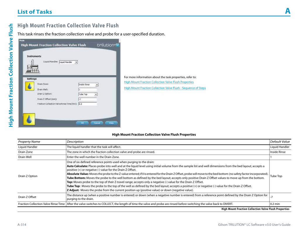
List of Tasks A
A-314 Gilson TRILUTION® LC Software v3.0 User’s Guide
Hig
h M
ount
Fra
ctio
n Co
llect
ion
Valv
e Fl
ush High Mount Fraction Collection Valve Flush
This task rinses the fraction collection valve and probe for a user-specified duration.
For more information about the task properties, refer to:
High Mount Fraction Collection Valve Flush Properties
High Mount Fraction Collection Valve Flush - Sequence of Steps
High Mount Fraction Collection Valve Flush Properties
Property Name Description Default Value
Liquid Handler The liquid handler that the task will affect. Liquid Handler
Drain Zone The zone in which the fraction collection valve and probe are rinsed. Inside Rinse
Drain Well Enter the well number in the Drain Zone. 1
Drain Z Option
One of six defined reference points used when purging to the drain:Auto Calculate: Places probe into well and at the liquid level using initial volume from the sample list and well dimensions from the bed layout; accepts a positive (+) or negative (-) value for the Drain Z Offset.Absolute Value: Moves the probe to the Z-value entered; if 0 is entered for the Drain Z Offset, probe will move to the bed bottom (no safety factor incorporated).Tube Bottom: Moves the probe to the well bottom as defined by the bed layout; accepts only positive Drain Z Offset values to move up from the bottom.Top: Moves probe to the top of their Z-travel range; accepts only a negative (-) value for the Drain Z Offset.Tube Top: Moves the probe to the top of the well as defined by the bed layout; accepts a positive (+) or negative (-) value for the Drain Z Offset.Z Adjust: Moves the probe from the current position up (positive value) or down (negative value).
Tube Top
Drain Z Offset The distance up (when a positive number is entered) or down (when a negative number is entered) from a reference point defined by the Drain Z Option for purging to the drain. -7
Fraction Collection Valve Rinse Time After the valve switches to COLLECT, the length of time the valve and probe are rinsed before switching the valve back to DIVERT. 0.2 min
High Mount Fraction Collection Valve Flush Properties

Gilson TRILUTION® LC Software v3.0 User’s Guide A-315
List of Tasks AH
igh Mount Fraction Collection Valve Flush
High Mount Fraction Collection Valve Flush - Sequence of Steps1 Move Z to Z Safe Height.2 Move to Drain Well in Drain Zone.3 Lower probe into well to Drain Z Option and Drain Z Offset.4 Switch fraction collection valve to COLLECT for Fraction Collection Valve Rinse Time then switch the fraction collection valve to DIVERT.5 Move Z to Z Safe Height.

List of Tasks A
A-316 Gilson TRILUTION® LC Software v3.0 User’s Guide
Hom
e Fr
acti
on C
olle
ctor Home Fraction Collector
This task homes the specified Fraction Collector.
Home Fraction Collector - Sequence of Steps1 Move to home position at the left rear of the X and Y matrix.
For more information about the task properties, refer to:
Home Fraction Collector Properties
Home Fraction Collector - Sequence of Steps
Home Fraction Collector Properties
Property Name Description Default Value
Fraction Collector The fraction collector that the task will affect. Fraction Collector
Home Fraction Collector Properties

Gilson TRILUTION® LC Software v3.0 User’s Guide A-317
List of Tasks AH
ome Liquid H
andler
Home Liquid HandlerThis task homes the specified liquid handler.
For more information about the task properties, refer to:
Home Liquid Handler Properties
Home Liquid Handler - Sequence of Steps
Home Liquid Handler Properties
Property Name Brief Description Default Value
Liquid Handler The liquid handler that the task will affect. Liquid Handler
Pump The pump that the task will affect. Pump
Inside Rinse Zone The zone at which the Dilutor is homed. Inside Rinse
Inside Rinse Well Enter the well number in the Inside Rinse Zone. 1
Z Option
One of six defined reference points used when performing the move:Auto Calculate: Places probe into well and at the liquid level using initial volume from the sample list and well dimensions from the bed layout; accepts a positive (+) or negative (-) value for the Z Offset.Absolute Value: Moves the probe to the Z-value entered; if 0 is entered, probe will move to the bed bottom (no safety factor incorporated).Tube Bottom: Moves the probe to the well bottom as defined by the bed layout; accepts only positive Z Offset values to move up from the bottom.Top: Moves probe to the top of their Z-travel range; accepts only a negative (-) value for the Z Offset.Tube Top: Moves the probe to the top of the well as defined by the bed layout; accepts a positive (+) or negative (-) value for the Z Offset.Z Adjust: Moves the probe from the current position up (positive value) or down (negative value).
Tube Bottom
Z Offset The distance up (when a positive number is entered) or down (when a negative number is entered) from a reference point defined by the Z Option. 2 mm
Home Liquid Handler Properties

List of Tasks A
A-318 Gilson TRILUTION® LC Software v3.0 User’s Guide
Hom
e Li
quid
Han
dler Home Liquid Handler - Sequence of Steps
1 Home the X/Y/Z of the Liquid Handler.2 Move the probe to Inside Rinse Well in Inside Rinse Zone.3 Lower probe to Z Option and Z Offset.4 Home dilutor.5 Move Z to Z Safe Height.

Gilson TRILUTION® LC Software v3.0 User’s Guide A-319
List of Tasks AInjection Rinse
Injection RinseThis task rinses the injection port and must be synchronized with a Move to Sample Location task to move the probe to the injection port prior to rinsing.
For more information about the task properties, refer to:
Injection Rinse Properties
Injection Rinse Properties
Property Name Description Default Value
Liquid Handler The liquid handler that the task will affect. Liquid Handler
Pump The pump that the task will affect. Pump
Rinse Volume The quantity of liquid dispensed. 1000 μL
Rinse Flow Rate The speed at which the Rinse Volume moves out of the probe and into the injection port. 3 mL/min
Injection Rinse Properties
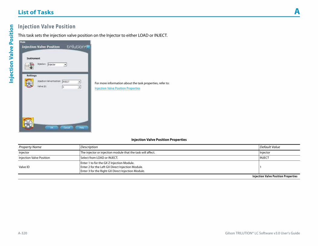
List of Tasks A
A-320 Gilson TRILUTION® LC Software v3.0 User’s Guide
Inje
ctio
n Va
lve
Posi
tion Injection Valve Position
This task sets the injection valve position on the Injector to either LOAD or INJECT.
For more information about the task properties, refer to:
Injection Valve Position Properties
Injection Valve Position Properties
Property Name Description Default Value
Injector The injector or injection module that the task will affect. Injector
Injection Valve Position Select from LOAD or INJECT. INJECT
Valve IDEnter 1 to for the GX Z Injection Module.Enter 2 for the Left GX Direct Injection Module.Enter 3 for the Right GX Direct Injection Module.
1
Injection Valve Position Properties

Gilson TRILUTION® LC Software v3.0 User’s Guide A-321
List of Tasks AInside Rinse
Inside RinseThis task moves to the rinse station and then rinses the inside of the probe.
For more information about the task properties, refer to:
Inside Rinse Properties
Inside Rinse - Sequence of Steps
Inside Rinse Properties For information about rinse positions, refer to Appendix B, Rinse Locations.
Property Name Description Default Value
Liquid Handler The liquid handler that the task will affect. Liquid Handler
Pump The pump that the task will affect. Pump
Inside Rinse Zone The zone to which the Rinse Volume is delivered. Inside Rinse
Inside Rinse Well Enter the well number in the Inside Rinse Zone. 1
Rinse Volume The quantity of liquid used to rinse the inside of the probe. 1000 μL
Rinse Flow Rate The speed at which the Rinse Volume moves out of the probe and into the inside rinse position in the rinse station. 3 mL/min
Inside Rinse Properties (Page 1 of 2)

List of Tasks A
A-322 Gilson TRILUTION® LC Software v3.0 User’s Guide
Insi
de R
inse
Inside Rinse - Sequence of Steps1 Move Z to Z Safe Height.2 Move to Inside Rinse Well in Inside Rinse Zone.3 Lower probe into well to Inside Rinse Z Option and Inside Rinse Z Offset.4 Home dilutor.5 Switch dilutor valve to reservoir and aspirate Rinse Volume or syringe capacity at Rinse Flow Rate.6 Switch dilutor valve to probe and dispense Rinse Volume or syringe capacity at Rinse Flow Rate.7 Repeat steps 5–6 until requested rinse volume is aspirated and dispensed.
Inside Rinse Z Option
One of six defined reference points used when performing the inside rinse:Auto Calculate: Places probe into well and at the liquid level using initial volume from the sample list and well dimensions from the bed layout; accepts a positive (+) or negative (-) value for the Inside Rinse Z Offset.Absolute Value: Moves the probe to the Z-value entered; if 0 is entered, probe will move to the bed bottom (no safety factor incorporated).Tube Bottom: Moves the probe to the well bottom as defined by the bed layout; accepts only positive Inside Rinse Z Offset values to move up from the bottom.Top: Moves probe to the top of their Z-travel range; accepts only a negative (-) value for the Inside Rinse Z Offset.Tube Top: Moves the probe to the top of the well as defined by the bed layout; accepts a positive (+) or negative (-) value for the Inside Rinse Z Offset.Z Adjust: Moves the probe from the current position up (positive value) or down (negative value).
Tube Bottom
Inside Rinse Z Offset The distance up (when a positive number is entered) or down (when a negative number is entered) from a reference point defined by the Inside Rinse Z Option for rinsing the probe at the inside rinse position in the rinse station. 2 mm
Inside Rinse Properties (Continued)For information about rinse positions, refer to Appendix B, Rinse Locations.
Property Name Description Default Value
Inside Rinse Properties (Page 2 of 2)
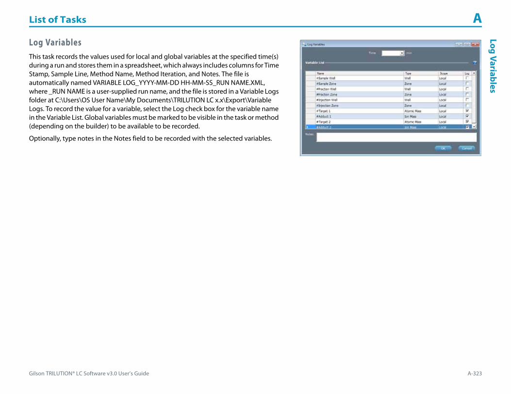
Gilson TRILUTION® LC Software v3.0 User’s Guide A-323
List of Tasks ALog Variables
Log VariablesThis task records the values used for local and global variables at the specified time(s) during a run and stores them in a spreadsheet, which always includes columns for Time Stamp, Sample Line, Method Name, Method Iteration, and Notes. The file is automatically named VARIABLE LOG_YYYY-MM-DD HH-MM-SS_RUN NAME.XML, where _RUN NAME is a user-supplied run name, and the file is stored in a Variable Logs folder at C:\Users\OS User Name\My Documents\TRILUTION LC x.x\Export\Variable Logs. To record the value for a variable, select the Log check box for the variable name in the Variable List. Global variables must be marked to be visible in the task or method (depending on the builder) to be available to be recorded.
Optionally, type notes in the Notes field to be recorded with the selected variables.

List of Tasks A
A-324 Gilson TRILUTION® LC Software v3.0 User’s Guide
Low
Vol
ume
Part
ial L
oop
Inje
ctio
n Low Volume Partial Loop InjectionThis task performs a partial loop injection using a push volume from the reservoir to push the injection volume into the sample loop.
For more information about the properties on each tab, refer to:
Low Volume Partial Loop Injection Properties - Main
Low Volume Partial Loop Injection Properties - Advanced
Low Volume Partial Loop Injection Properties - Rinsing
Low Volume Partial Loop Injection - Sequence of Steps
Low Volume Partial Loop Injection Properties - Main
Property Name Description Default Value
Liquid Handler The liquid handler that the task will affect. Liquid Handler
Pump The pump that the task will affect. Pump
Injector The injector or injection module that the task will affect. Liquid Handler
Sample Zone The zone from which the Injection Volume and Extra Volume are aspirated. Sample Zone
Sample Well Enter the well number in the Sample Zone. 0
Injection Zone The zone to which the Extra Volume, Injection Volume, and Push Volume are dispensed. Injection Zone
Low Volume Partial Loop Injection Properties - Main (Page 1 of 2)
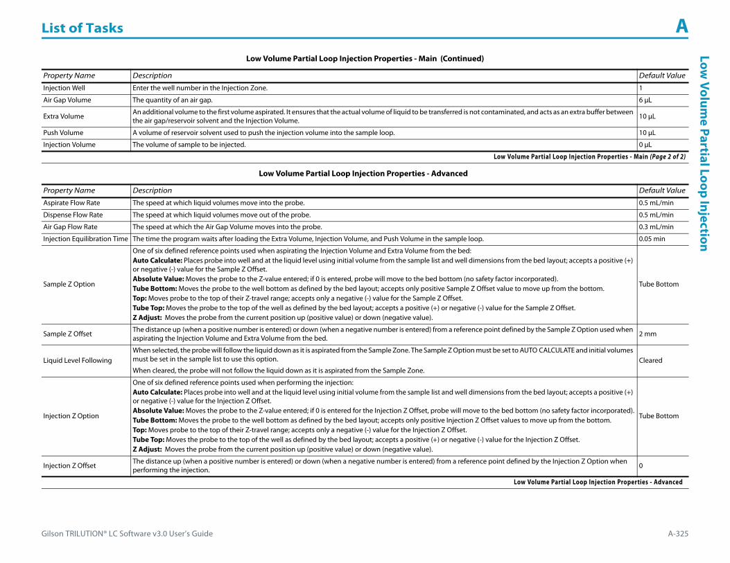
Gilson TRILUTION® LC Software v3.0 User’s Guide A-325
List of Tasks ALow
Volume Partial Loop Injection
Injection Well Enter the well number in the Injection Zone. 1
Air Gap Volume The quantity of an air gap. 6 μL
Extra Volume An additional volume to the first volume aspirated. It ensures that the actual volume of liquid to be transferred is not contaminated, and acts as an extra buffer between the air gap/reservoir solvent and the Injection Volume. 10 μL
Push Volume A volume of reservoir solvent used to push the injection volume into the sample loop. 10 μL
Injection Volume The volume of sample to be injected. 0 μL
Low Volume Partial Loop Injection Properties - Advanced
Property Name Description Default Value
Aspirate Flow Rate The speed at which liquid volumes move into the probe. 0.5 mL/min
Dispense Flow Rate The speed at which liquid volumes move out of the probe. 0.5 mL/min
Air Gap Flow Rate The speed at which the Air Gap Volume moves into the probe. 0.3 mL/min
Injection Equilibration Time The time the program waits after loading the Extra Volume, Injection Volume, and Push Volume in the sample loop. 0.05 min
Sample Z Option
One of six defined reference points used when aspirating the Injection Volume and Extra Volume from the bed:Auto Calculate: Places probe into well and at the liquid level using initial volume from the sample list and well dimensions from the bed layout; accepts a positive (+) or negative (-) value for the Sample Z Offset.Absolute Value: Moves the probe to the Z-value entered; if 0 is entered, probe will move to the bed bottom (no safety factor incorporated).Tube Bottom: Moves the probe to the well bottom as defined by the bed layout; accepts only positive Sample Z Offset value to move up from the bottom.Top: Moves probe to the top of their Z-travel range; accepts only a negative (-) value for the Sample Z Offset.Tube Top: Moves the probe to the top of the well as defined by the bed layout; accepts a positive (+) or negative (-) value for the Sample Z Offset.Z Adjust: Moves the probe from the current position up (positive value) or down (negative value).
Tube Bottom
Sample Z Offset The distance up (when a positive number is entered) or down (when a negative number is entered) from a reference point defined by the Sample Z Option used when aspirating the Injection Volume and Extra Volume from the bed. 2 mm
Liquid Level FollowingWhen selected, the probe will follow the liquid down as it is aspirated from the Sample Zone. The Sample Z Option must be set to AUTO CALCULATE and initial volumes must be set in the sample list to use this option.
When cleared, the probe will not follow the liquid down as it is aspirated from the Sample Zone.Cleared
Injection Z Option
One of six defined reference points used when performing the injection:Auto Calculate: Places probe into well and at the liquid level using initial volume from the sample list and well dimensions from the bed layout; accepts a positive (+) or negative (-) value for the Injection Z Offset.Absolute Value: Moves the probe to the Z-value entered; if 0 is entered for the Injection Z Offset, probe will move to the bed bottom (no safety factor incorporated).Tube Bottom: Moves the probe to the well bottom as defined by the bed layout; accepts only positive Injection Z Offset values to move up from the bottom.Top: Moves probe to the top of their Z-travel range; accepts only a negative (-) value for the Injection Z Offset.Tube Top: Moves the probe to the top of the well as defined by the bed layout; accepts a positive (+) or negative (-) value for the Injection Z Offset.Z Adjust: Moves the probe from the current position up (positive value) or down (negative value).
Tube Bottom
Injection Z Offset The distance up (when a positive number is entered) or down (when a negative number is entered) from a reference point defined by the Injection Z Option when performing the injection. 0
Low Volume Partial Loop Injection Properties - Advanced
Low Volume Partial Loop Injection Properties - Main (Continued)
Property Name Description Default Value
Low Volume Partial Loop Injection Properties - Main (Page 2 of 2)

List of Tasks A
A-326 Gilson TRILUTION® LC Software v3.0 User’s Guide
Low
Vol
ume
Part
ial L
oop
Inje
ctio
n
Low Volume Partial Loop Injection Properties - Rinsing For information about rinse positions, refer to Appendix B, Rinse Locations.
Property Name Description Default Value
Drain Zone The zone in which the dilutor is homed. Inside Rinse
Drain Well Enter the well number in the Drain Zone. 1
Drain Z Option
One of six defined reference points used when purging to the drain:Auto Calculate: Places probe into well and at the liquid level using initial volume from the sample list and well dimensions from the bed layout; accepts a positive (+) or negative (-) value for the Drain Z Offset.Absolute Value: Moves the probe to the Z-value entered; if 0 is entered for the Drain Z Offset, probe will move to the bed bottom (no safety factor incorporated).Tube Bottom: Moves the probe to the well bottom as defined by the bed layout; accepts only positive Drain Z Offset values to move up from the bottom.Top: Moves probe to the top of their Z-travel range; accepts only a negative (-) value for the Drain Z Offset.Tube Top: Moves the probe to the top of the well as defined by the bed layout; accepts a positive (+) or negative (-) value for the Drain Z Offset.Z Adjust: Moves the probe from the current position up (positive value) or down (negative value).
Tube Top
Drain Z Offset The distance up (when a positive number is entered) or down (when a negative number is entered) from a reference point defined by the Drain Z Option for purging to the drain. -7
Injection Rinse Volume The quantity of liquid used to rinse the injection port at Injection Well in Injection Zone. 500 μL
Injection Rinse Flow Rate The speed at which the Injection Rinse Volume moves out of the probe and into the injection port. 4 mL/min
Outside Rinse Zone The zone to which the Outside Rinse Volume is delivered. Outside Rinse
Outside Rinse Well Enter the well number in the Outside Rinse Zone. 1
Outside Rinse Volume The quantity of liquid used to rinse the outside of the probe. 500 μL
Outside Rinse Flow Rate The speed at which the Outside Rinse Volume moves out of the probe and into the outside rinse position in the rinse station. 10 mL/min
Outside Rinse Z Option
One of six defined reference points used when performing the outside rinse:Auto Calculate: Places probe into well and at the liquid level using initial volume from the sample list and well dimensions from the bed layout; accepts a positive (+) or negative (-) value for the Outside Rinse Z Offset.Absolute Value: Moves the probe to the Z-value entered; if 0 is entered, probe will move to the bed bottom (no safety factor incorporated).Tube Bottom: Moves the probe to the well bottom as defined by the bed layout; accepts only positive Outside Rinse Z Offset values to move up from the bottom.Top: Moves probe to the top of their Z-travel range; accepts only a negative (-) value for the Outside Rinse Z Offset.Tube Top: Moves the probe to the top of the well as defined by the bed layout; accepts a positive (+) or negative (-) value for the Outside Rinse Z Offset.Z Adjust: Moves the probe from the current position up (positive value) or down (negative value).
Tube Bottom
Outside Rinse Z Offset The distance up (when a positive number is entered) or down (when a negative number is entered) from a reference point defined by the Outside Rinse Z Option for rinsing the probe at the outside rinse position in the rinse station. 2 mm
Low Volume Partial Loop Injection Properties - Rinsing

Gilson TRILUTION® LC Software v3.0 User’s Guide A-327
List of Tasks ALow
Volume Partial Loop Injection
Low Volume Partial Loop Injection - Sequence of StepsThe following is an overview for the sequence of steps.
1 Initialize2 Aspirate3 Inject4 Injection Port Rinse5 Outside Rinse
Initialize1 Move Z to Z Safe Height.2 Set injection valve to INJECT.3 Move to Drain Well in Drain Zone.4 Lower probe into well to Drain Z Option and Drain Z Offset.5 Home dilutor.6 Move Z to Z Safe Height.
Aspirate1 Aspirate Air Gap Volume at Air Gap Flow Rate.2 Aspirate Push Volume at Aspirate Flow Rate from Reservoir.3 Move to Sample Well in Sample Zone.4 Lower probe into well to Sample Z Option and Sample Z Offset.5 Aspirate Injection Volume + Extra Volume at Aspirate Flow Rate.6 Move Z to Z Safe Height.
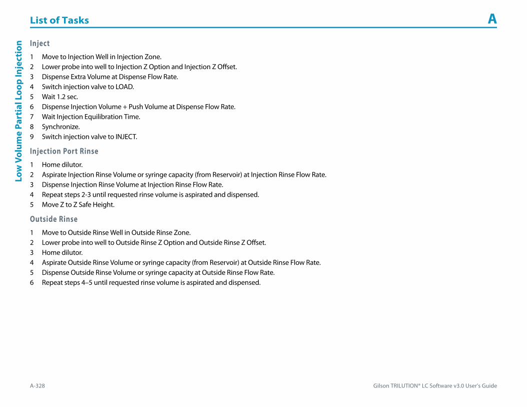
List of Tasks A
A-328 Gilson TRILUTION® LC Software v3.0 User’s Guide
Low
Vol
ume
Part
ial L
oop
Inje
ctio
n Inject1 Move to Injection Well in Injection Zone.2 Lower probe into well to Injection Z Option and Injection Z Offset.3 Dispense Extra Volume at Dispense Flow Rate.4 Switch injection valve to LOAD.5 Wait 1.2 sec.6 Dispense Injection Volume + Push Volume at Dispense Flow Rate.7 Wait Injection Equilibration Time.8 Synchronize.9 Switch injection valve to INJECT.
Injection Port Rinse1 Home dilutor.2 Aspirate Injection Rinse Volume or syringe capacity (from Reservoir) at Injection Rinse Flow Rate.3 Dispense Injection Rinse Volume at Injection Rinse Flow Rate.4 Repeat steps 2-3 until requested rinse volume is aspirated and dispensed.5 Move Z to Z Safe Height.
Outside Rinse1 Move to Outside Rinse Well in Outside Rinse Zone.2 Lower probe into well to Outside Rinse Z Option and Outside Rinse Z Offset.3 Home dilutor.4 Aspirate Outside Rinse Volume or syringe capacity (from Reservoir) at Outside Rinse Flow Rate.5 Dispense Outside Rinse Volume or syringe capacity at Outside Rinse Flow Rate.6 Repeat steps 4–5 until requested rinse volume is aspirated and dispensed.

Gilson TRILUTION® LC Software v3.0 User’s Guide A-329
List of Tasks AM
ass Spec Auto Tune
Mass Spec Auto TuneThis task tunes the Flexar SQ 300 MS Detector across a specified mass range using a specified tune mix.
Run this task using Manual Control (NOT as part of a method).
For more information about the task properties, refer to:
Mass Spec Auto Tune Properties
Mass Spec Auto Tune Properties
Property Name Description Default Value
Detector The detector that the task will affect. MS Detector
Tune Mix Source Select from Vial 1, Vial 2, Syringe, or External. Vial 1
Prime Select to prime the tubing between the Tune Mix Source and the diverter valve. Cleared
Mass Spec Auto Tune Properties (Page 1 of 2)

List of Tasks A
A-330 Gilson TRILUTION® LC Software v3.0 User’s Guide
Mas
s Sp
ec A
uto
Tune
Diverter Position Select from Tune Mix or Sample. Tune Mix
Tune Mass Settings
Select from Use Previous Settings (to use settings from the last positive and/or negative auto tune), Create New Positive Settings (to tune the MS Detector for positive ionization), or Create New Negative Settings (to tune the MS Detector for negative ionization).
It may be necessary (and is necessary for the first auto tune) to run the auto tune twice: once for positive settings and once for negative settings.
Default settings are for use with the tune mix Electrospray Calibrant Solution, 100 mL (part number 18007062), which must be diluted 1:10 in 95%/5% (v/v) Acetonitrile/Water.
Use Previous Settings
Use Previous Settings
Tune Mix Polarity When Use Previous Settings is selected, select from Positive or Negative. Positive
Create New Positive Settings or Create New Negative Settings
Name Optionally, name the peaks to be found at the masses present in the tune mix. By default, they are named by number 1–7.
Mass Enter the mass values for the peaks that should be present in the tune mix. Default settings are for use with the tune mix Electrospray Calibrant Solution, 100 mL (part number 18007062), which must be diluted 1:10 in 95%/5% (v/v) Acetonitrile/Water.
m/z
AreaEnter a value that will be used as pass/fail criteria for the auto tune. The peak with the largest area of the peaks found in the tune is assigned a value of 100% by the software. If, for example, a value of 30 is entered for the Area for a peak, then the area for that peak must be greater than or equal to 30% of the peak with the largest area. If it is not, that will be reflected in the check tune report.
%
Capillary Exit Enter a value that will be used as a capillary exit voltage for the specified mass. The Capillary Exit Voltage has the function of pushing ions of the same sign away from the exit as they emerge from the capillary. As a general trend, a higher capillary exit voltage increases fragmentation of the low mass ions, and increases abundance of the high mass ions. V
Use Select for each mass to use for the auto tune. By default, six masses are selected for use with the tune mix Electrospray Calibrant Solution, 100 mL (part number 18007062), which must be diluted 1:10 in 95%/5% (v/v) Acetonitrile/Water.
Mass Spec Auto Tune Properties (Continued)
Property Name Description Default Value
Mass Spec Auto Tune Properties (Page 2 of 2)

Gilson TRILUTION® LC Software v3.0 User’s Guide A-331
List of Tasks AM
ass Spec Check Tune
Mass Spec Check TuneThis task verifies that the Flexar SQ 300 MS Detector is tuned across a specified mass range using a specified tune mix.
Run this task using Manual Control (NOT as part of a method).
For more information about the task properties, refer to:
Mass Spec Check Tune Properties
Mass Spec Check Tune Properties
Property Name Description Default Value
Detector The detector that the task will affect. MS Detector
Tune Mix Source Select from Vial 1, Vial 2, Syringe, or External. Vial 1
Prime Select to prime the tubing between the Tune Mix Source and the diverter valve. Cleared
Diverter Position Select from Tune Mix or Sample. Tune Mix
Use By default, the check tune uses the diverter valve. Selected
Tune Mix Polarity Select from Positive or Negative. Positive
Save ResultsWhen selected, the results of the check tune will be saved and accessible from the Tune/Diagnostics Tab in the Results.
When cleared, the results of the check tune will not be saved.Selected
Mass Spec Check Tune Properties
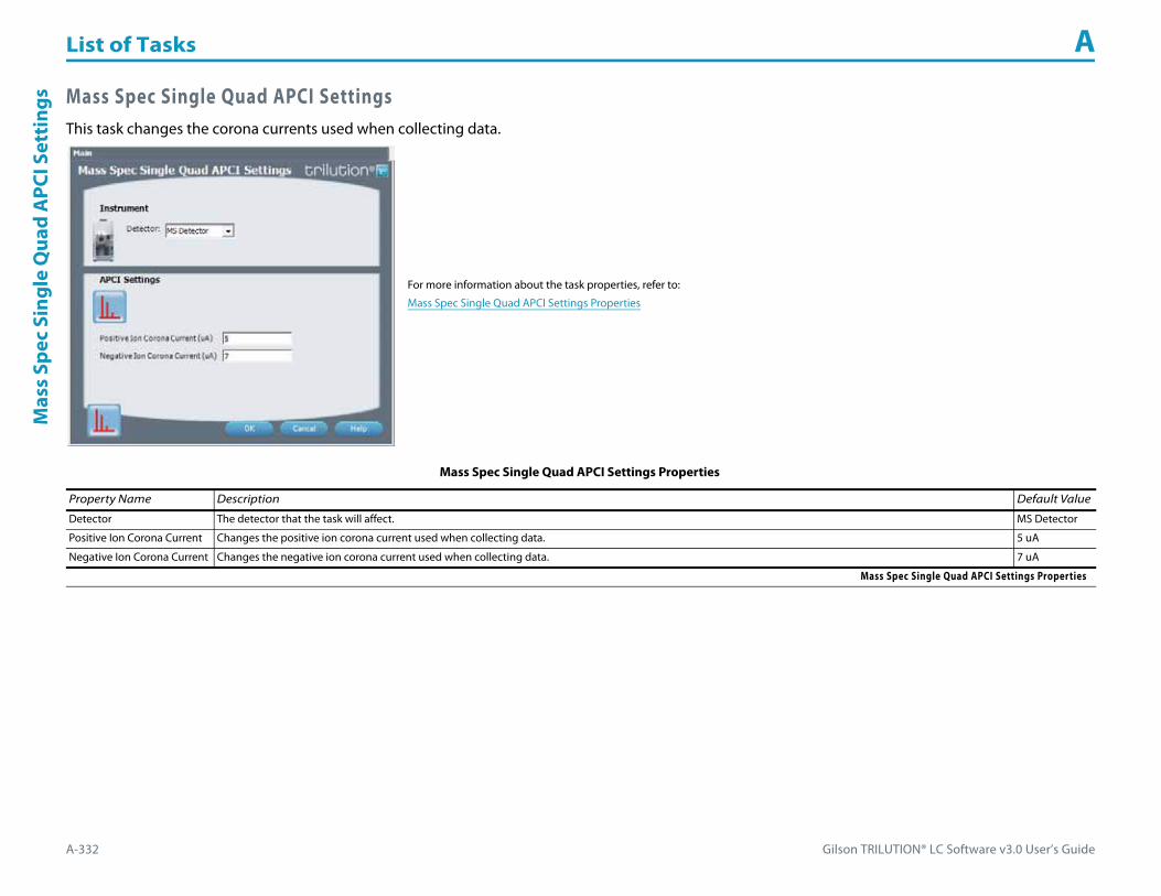
List of Tasks A
A-332 Gilson TRILUTION® LC Software v3.0 User’s Guide
Mas
s Sp
ec S
ingl
e Q
uad
APC
I Set
ting
s Mass Spec Single Quad APCI SettingsThis task changes the corona currents used when collecting data.
For more information about the task properties, refer to:
Mass Spec Single Quad APCI Settings Properties
Mass Spec Single Quad APCI Settings Properties
Property Name Description Default Value
Detector The detector that the task will affect. MS Detector
Positive Ion Corona Current Changes the positive ion corona current used when collecting data. 5 uA
Negative Ion Corona Current Changes the negative ion corona current used when collecting data. 7 uA
Mass Spec Single Quad APCI Settings Properties
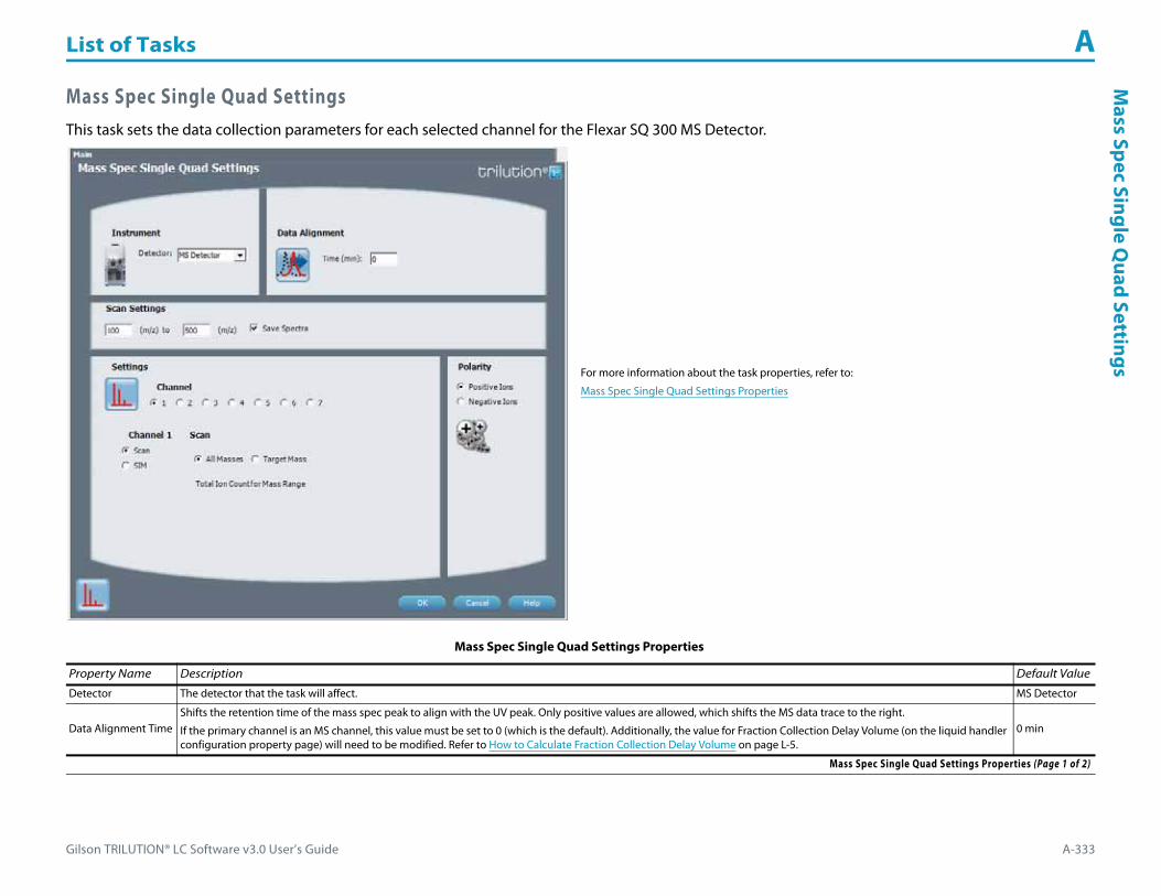
Gilson TRILUTION® LC Software v3.0 User’s Guide A-333
List of Tasks AM
ass Spec Single Quad Settings
Mass Spec Single Quad SettingsThis task sets the data collection parameters for each selected channel for the Flexar SQ 300 MS Detector.
For more information about the task properties, refer to:
Mass Spec Single Quad Settings Properties
Mass Spec Single Quad Settings Properties
Property Name Description Default Value
Detector The detector that the task will affect. MS Detector
Data Alignment TimeShifts the retention time of the mass spec peak to align with the UV peak. Only positive values are allowed, which shifts the MS data trace to the right.
If the primary channel is an MS channel, this value must be set to 0 (which is the default). Additionally, the value for Fraction Collection Delay Volume (on the liquid handler configuration property page) will need to be modified. Refer to How to Calculate Fraction Collection Delay Volume on page L-5.
0 min
Mass Spec Single Quad Settings Properties (Page 1 of 2)

List of Tasks A
A-334 Gilson TRILUTION® LC Software v3.0 User’s Guide
Mas
s Sp
ec S
ingl
e Q
uad
Sett
ings
Scan Settings
RangeEnter the beginning and ending masses in the full scan range. (Range limits 50–3000 m/z.)
For the recommended scan range for each data rate, refer to Recommended Maximum Scan Range (High m/z – Low m/z) on page L-6.100–500 m/z
Save SpectraSelect to save the spectral data from a scan at the end of the run.
If choosing not to save spectra, the fraction spectra will still be saved.Selected
Settings
Channel Select channel number for which data collection parameters will be set. Repeat for each channel to be used. (1–7) 1
Scan Select to monitor a specified scan range. Selected
ScanAll Masses
Select to display the data trace as the total ion count for the masses within the specified scan range.
Do not associate an analysis with the data channel used for the scan of all masses. An analysis can be browsed in post-run and data re-analyzed.Selected
ScanTarget Mass
Select to display the data trace as the specified mass with one to three adducts (extracted ion or extracted ions). If Save Spectra was selected (it is by default), the data for the full scan range will be saved and can be viewed as spectral data.
Cleared
ScanTarget MassTarget
Enter the mass. 100 amu
ScanTarget MassAdduct
Enter values for one to three adducts. Select the box for adducts to be used and then enter a value for each.
Intensity Displayed = (Intensity of Mass + Adduct 1) + (Intensity of Mass + Adduct 2) + (Intensity of Mass + Adduct 3)1 m/z
SIM Select to monitor a target mass with adducts (Selected Ion Monitoring). Cleared
SIMTarget
Enter the mass. 100 amu
SIMAdduct
Enter values for one to three adducts. Select the box for adducts to be used and then enter a value for each.
Intensity Displayed = (Intensity of Mass + Adduct 1) + (Intensity of Mass + Adduct 2) + (Intensity of Mass + Adduct 3)1 m/z
Polarity
Positive Ions Select to form positive ions. Adduct values are added to the target when forming positive ions. Selected
Negative Ions Select to form negative ions. Adduct values are subtracted from the target when forming negative ions. Cleared
Mass Spec Single Quad Settings Properties (Continued)
Property Name Description Default Value
Mass Spec Single Quad Settings Properties (Page 2 of 2)

Gilson TRILUTION® LC Software v3.0 User’s Guide A-335
List of Tasks AM
ass Spec Single Quad Standby
Mass Spec Single Quad StandbyThis task puts the Flexar SQ 300 MS Detector in standby.
For more information about the task properties, refer to:
Mass Spec Single Quad Standby Properties
Mass Spec Single Quad Standby Properties
Property Name Description Default Value
Detector The detector that the task will affect. MS Detector
Mass Spec Single Quad Standby Properties

List of Tasks A
A-336 Gilson TRILUTION® LC Software v3.0 User’s Guide
Mas
s Sp
ec S
ingl
e Q
uad
Star
t Up Mass Spec Single Quad Start Up
This task sets the dry gas flow and temperature, the nebulizer gas pressure, and the APCI vaporizer temperature (if applicable) on the Flexar SQ 300 MS Detector.
For more information about the task properties, refer to:
Mass Spec Single Quad Start Up Properties
Mass Spec Single Quad Start Up Properties
Property Name Description Default Value
Detector The detector that the task will affect. MS Detector
Settings - ESI
Dry Gas Flow Sets the flow rate of the drying gas flowing in direction counter to the analyte spray. 15000 mL/min
Dry Gas Temperature Sets the temperature of the drying gas flowing in direction counter to the analyte spray. 350°C
Nebulizer Gas Pressure Sets the pressure that controls the amount of gas flowing concentrically to the analyte spray to create sample aerosol. 80 psi
Settings - APCI
Dry Gas Flow Sets the flow rate of the drying gas flowing in direction counter to the analyte spray. 8000 mL/min
Dry Gas Temperature Sets the temperature of the drying gas flowing in direction counter to the analyte spray. 300°C
Nebulizer Gas Pressure Sets the pressure that controls the amount of gas flowing concentrically to the analyte spray to create sample aerosol. 25psi
Mass Spec Single Quad Start Up Properties (Page 1 of 2)

Gilson TRILUTION® LC Software v3.0 User’s Guide A-337
List of Tasks AM
ass Spec Single Quad Start U
p
APCI Vaporizer Temperature Sets the APCI vaporizer temperature. 300°C
Wait for PressureWhen selected, sends all user-specified parameters immediately, except APCI Vaporizer Temperature, which is sent 30 seconds later.
When cleared, sends all user-specified parameters immediately.Selected
Mass Spec Single Quad Start Up Properties (Continued)
Property Name Description Default Value
Mass Spec Single Quad Start Up Properties (Page 2 of 2)

List of Tasks A
A-338 Gilson TRILUTION® LC Software v3.0 User’s Guide
Mix
wit
h A
ir Mix with AirThis task aspirates air and then dispenses it into a well a specified number of times.
For more information about the properties on each tab, refer to:
Mix with Air Properties - Main
Mix with Air Properties - Advanced
Mix with Air Properties - Rinsing
Mix with Air - Sequence of Steps
Mix with Air Properties - Main
Property Name Brief Description Default Value
Liquid Handler The liquid handler that the task will affect. Liquid Handler
Pump The pump that the task will affect. Pump
Mixing Zone The zone in which the Mixing Volume is mixed. Sample Zone
Mixing Well Enter the well number in the Mixing Zone. 0
Number of Wells to Mix The number of Mixing Wells to mix. 1
Number of Cycles Type the number of times the task should repeat the commands related to mixing. 2
Mix with Air Properties - Main (Page 1 of 2)
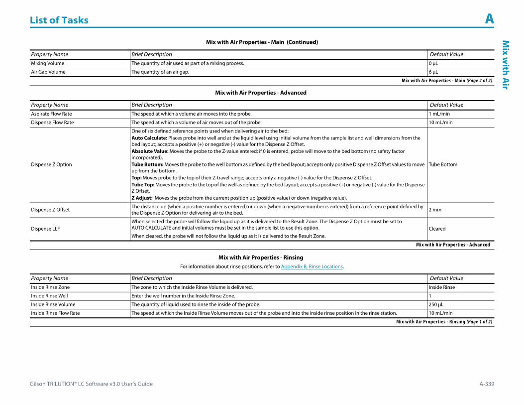
Gilson TRILUTION® LC Software v3.0 User’s Guide A-339
List of Tasks AM
ix with A
ir
Mixing Volume The quantity of air used as part of a mixing process. 0 μL
Air Gap Volume The quantity of an air gap. 6 μL
Mix with Air Properties - Advanced
Property Name Brief Description Default Value
Aspirate Flow Rate The speed at which a volume air moves into the probe. 1 mL/min
Dispense Flow Rate The speed at which a volume of air moves out of the probe. 10 mL/min
Dispense Z Option
One of six defined reference points used when delivering air to the bed:Auto Calculate: Places probe into well and at the liquid level using initial volume from the sample list and well dimensions from the bed layout; accepts a positive (+) or negative (-) value for the Dispense Z Offset.Absolute Value: Moves the probe to the Z-value entered; if 0 is entered, probe will move to the bed bottom (no safety factor incorporated).Tube Bottom: Moves the probe to the well bottom as defined by the bed layout; accepts only positive Dispense Z Offset values to move up from the bottom.Top: Moves probe to the top of their Z-travel range; accepts only a negative (-) value for the Dispense Z Offset.Tube Top: Moves the probe to the top of the well as defined by the bed layout; accepts a positive (+) or negative (-) value for the Dispense Z Offset.Z Adjust: Moves the probe from the current position up (positive value) or down (negative value).
Tube Bottom
Dispense Z Offset The distance up (when a positive number is entered) or down (when a negative number is entered) from a reference point defined by the Dispense Z Option for delivering air to the bed. 2 mm
Dispense LLFWhen selected the probe will follow the liquid up as it is delivered to the Result Zone. The Dispense Z Option must be set to AUTO CALCULATE and initial volumes must be set in the sample list to use this option.
When cleared, the probe will not follow the liquid up as it is delivered to the Result Zone.Cleared
Mix with Air Properties - Advanced
Mix with Air Properties - Rinsing For information about rinse positions, refer to Appendix B, Rinse Locations.
Property Name Brief Description Default Value
Inside Rinse Zone The zone to which the Inside Rinse Volume is delivered. Inside Rinse
Inside Rinse Well Enter the well number in the Inside Rinse Zone. 1
Inside Rinse Volume The quantity of liquid used to rinse the inside of the probe. 250 μL
Inside Rinse Flow Rate The speed at which the Inside Rinse Volume moves out of the probe and into the inside rinse position in the rinse station. 10 mL/min
Mix with Air Properties - Rinsing (Page 1 of 2)
Mix with Air Properties - Main (Continued)
Property Name Brief Description Default Value
Mix with Air Properties - Main (Page 2 of 2)

List of Tasks A
A-340 Gilson TRILUTION® LC Software v3.0 User’s Guide
Mix
wit
h A
ir
Mix with Air - Sequence of StepsThe following is an overview for the sequence of steps.
1 Mix2 Inside Rinse3 Outside Rinse
Inside Rinse Z Option
One of six defined reference points used when performing the inside rinse:Auto Calculate: Places probe into well and at the liquid level using initial volume from the sample list and well dimensions from the bed layout; accepts a positive (+) or negative (-) value for the Inside Rinse Z Offset.Absolute Value: Moves the probe to the Z-value entered; if 0 is entered, probe will move to the bed bottom (no safety factor incorporated).Tube Bottom: Moves the probe to the well bottom as defined by the bed layout; accepts only positive Inside Rinse Z Offset values to move up from the bottom.Top: Moves probe to the top of their Z-travel range; accepts only a negative (-) value for the Inside Rinse Z Offset.Tube Top: Moves the probe to the top of the well as defined by the bed layout; accepts a positive (+) or negative (-) value for the Inside Rinse Z Offset.Z Adjust: Moves the probe from the current position up (positive value) or down (negative value).
Tube Bottom
Inside Rinse Z Offset The distance up (when a positive number is entered) or down (when a negative number is entered) from a reference point defined by the Inside Rinse Z Option for rinsing the probe at the inside rinse position in the rinse station. 2 mm
Outside Rinse Zone The zone to which the Outside Rinse Volume is delivered. Outside Rinse
Outside Rinse Well Enter the well number in the Outside Rinse Zone. 1
Outside Rinse Volume The quantity of liquid used to rinse the outside of the probe. 500 μL
Outside Rinse Flow Rate The speed at which the Outside Rinse Volume moves out of the probe and into the outside rinse position in the rinse station. 10 mL/min
Outside Rinse Z Option
One of six defined reference points used when performing the outside rinse:Auto Calculate: Places probe into well and at the liquid level using initial volume from the sample list and well dimensions from the bed layout; accepts a positive (+) or negative (-) value for the Outside Rinse Z Offset.Absolute Value: Moves the probe to the Z-value entered; if 0 is entered, probe will move to the bed bottom (no safety factor incorporated).Tube Bottom: Moves the probe to the well bottom as defined by the bed layout; accepts only positive Outside Rinse Z Offset values to move up from the bottom.Top: Moves probe to the top of their Z-travel range; accepts only a negative (-) value for the Outside Rinse Z Offset.Tube Top: Moves the probe to the top of the well as defined by the bed layout; accepts a positive (+) or negative (-) value for the Outside Rinse Z Offset.Z Adjust: Moves the probe from the current position up (positive value) or down (negative value).
Tube Bottom
Outside Rinse Z Offset The distance up (when a positive number is entered) or down (when a negative number is entered) from a reference point defined by the Outside Rinse Z Option for rinsing the probe at the outside rinse position in the rinse station. 2 mm
Mix with Air Properties - Rinsing (Continued)For information about rinse positions, refer to Appendix B, Rinse Locations.
Property Name Brief Description Default Value
Mix with Air Properties - Rinsing (Page 2 of 2)

Gilson TRILUTION® LC Software v3.0 User’s Guide A-341
List of Tasks AM
ix with A
ir
Mix1 Move Z to Z Safe Height.2 Move to Mixing Well in Mixing Zone.3 Move Z to Z Safe Height.4 Aspirate Air Gap Volume at Air Gap Flow Rate (first cycle only).5 Aspirate Mixing Volume at Aspirate Flow Rate.6 Lower probe to Dispense Z Option and Dispense Z Offset.7 Dispense Mixing Volume at Dispense Flow Rate.8 Repeat steps 4–7 for Number of Cycles.9 Move Z to Z Safe Height.
Inside Rinse1 Move to Inside Rinse Well in Inside Rinse Zone.2 Lower probe into well to Inside Rinse Z Option and Inside Rinse Z Offset.3 Home dilutor.4 Aspirate Inside Rinse Volume or syringe capacity (from Reservoir) at Inside Rinse Flow Rate.5 Dispense Inside Rinse Volume or syringe capacity at Inside Rinse Flow Rate.6 Repeat steps 4–5 until requested rinse volume is aspirated and dispensed.7 Move Z to Z Safe Height.
Outside Rinse1 Move to Outside Rinse Well in Outside Rinse Zone.2 Lower probe into well to Outside Rinse Z Option and Outside Rinse Z Offset.3 Home dilutor.4 Aspirate Outside Rinse Volume or syringe capacity (from Reservoir) at Outside Rinse Flow Rate.5 Dispense Outside Rinse Volume or syringe capacity at Outside Rinse Flow Rate.6 Repeat steps 4–5 until requested rinse volume is aspirated and dispensed.7 Repeat Number of Wells to Mix.

List of Tasks A
A-342 Gilson TRILUTION® LC Software v3.0 User’s Guide
Mix
wit
h Li
quid Mix with Liquid
This task aspirates liquid and then dispenses it into a well a specified number of times.
For more information about the properties on each tab, refer to:
Mix with Liquid Properties - Main
Mix with Liquid Properties - Advanced
Mix with Liquid Properties - Rinsing
Mix with Liquid - Sequence of Steps
Mix with Liquid Properties - Main
Property Name Brief Description Default Value
Liquid Handler The liquid handler that the task will affect. Liquid Handler
Pump The pump that the task will affect. Pump
Mixing Zone The zone in which the Mixing Volume is mixed. Sample Zone
Mixing Well Enter the well number in the Mixing Zone. 0
Number of Wells to Mix The number of Mixing Wells to mix. 1
Number of Cycles Type the number of times the task should repeat the commands related to mixing. 2
Mix with Liquid Properties - Main (Page 1 of 2)

Gilson TRILUTION® LC Software v3.0 User’s Guide A-343
List of Tasks AM
ix with Liquid
Air Gap Volume The quantity of an air gap. 6 μL
Mixing Volume The quantity of liquid used as part of a mixing process. 0 μL
Mix with Liquid Properties - Advanced
Property Name Brief Description Default Value
Aspirate Flow Rate The speed at which the Mixing Volume moves into the probe. 1 mL/min
Dispense Flow Rate The speed at which the Mixing Volume moves out of the probe. 10 mL/min
Air Gap Flow Rate The speed at which the Air Gap Volume moves into the probe. 0.3 mL/min
Aspirate Z Option
One of six defined reference points used when drawing liquids from the bed:Auto Calculate: Places probe into well and at the liquid level using initial volume from the sample list and well dimensions from the bed layout; accepts a positive (+) or negative (-) value for the Aspirate Z Offset.Absolute Value: Moves the probe to the Z-value entered; if 0 is entered, probe will move to the bed bottom (no safety factor incorporated).Tube Bottom: Moves the probe to the well bottom as defined by the bed layout; accepts only positive Aspirate Z Offset values to move up from the bottom.Top: Moves probe to the top of their Z-travel range; accepts only a negative (-) value for the Aspirate Z Offset.Tube Top: Moves the probe to the top of the well as defined by the bed layout; accepts a positive (+) or negative (-) value for the Aspirate Z Offset.Z Adjust: Moves the probe from the current position up (positive value) or down (negative value).
Tube Bottom
Aspirate Z Offset The distance up (when a positive number is entered) or down (when a negative number is entered) from a reference point defined by the Aspirate Z Option for drawing liquids from the bed. 2 mm
Aspirate LLFWhen selected the probe will follow the liquid down as it is aspirated from the Mixing Zone. The Aspirate Z Option must be set to AUTO CALCULATE and initial volumes must be set in the sample list to use this option.
When cleared, the probe will not follow the liquid down as it is aspirated from the Mixing Zone.Cleared
Dispense Z Option
One of six defined reference points used when delivering liquids to the bed:Auto Calculate: Places probe into well and at the liquid level using initial volume from the sample list and well dimensions from the bed layout; accepts a positive (+) or negative (-) value for the Dispense Z Offset.Absolute Value: Moves the probe to the Z-value entered; if 0 is entered, probe will move to the bed bottom (no safety factor incorporated).Tube Bottom: Moves the probe to the well bottom as defined by the bed layout; accepts only positive Dispense Z Offset values to move up from the bottom.Top: Moves probe to the top of their Z-travel range; accepts only a negative (-) value for the Dispense Z Offset.Tube Top: Moves the probe to the top of the well as defined by the bed layout; accepts a positive (+) or negative (-) value for the Dispense Z Offset.Z Adjust: Moves the probe from the current position up (positive value) or down (negative value).
Tube Bottom
Dispense Z Offset The distance up (when a positive number is entered) or down (when a negative number is entered) from a reference point defined by the Dispense Z Option for delivering liquids to the bed. 2 mm
Dispense LLFWhen selected the probe will follow the liquid up as it is delivered to the Mixing Zone. The Dispense Z Option must be set to AUTO CALCULATE and initial volumes must be set in the sample list to use this option.
When cleared, the probe will not follow the liquid up as it is delivered to the Mixing Zone.Cleared
Mix with Liquid Properties - Advanced
Mix with Liquid Properties - Main (Continued)
Property Name Brief Description Default Value
Mix with Liquid Properties - Main (Page 2 of 2)
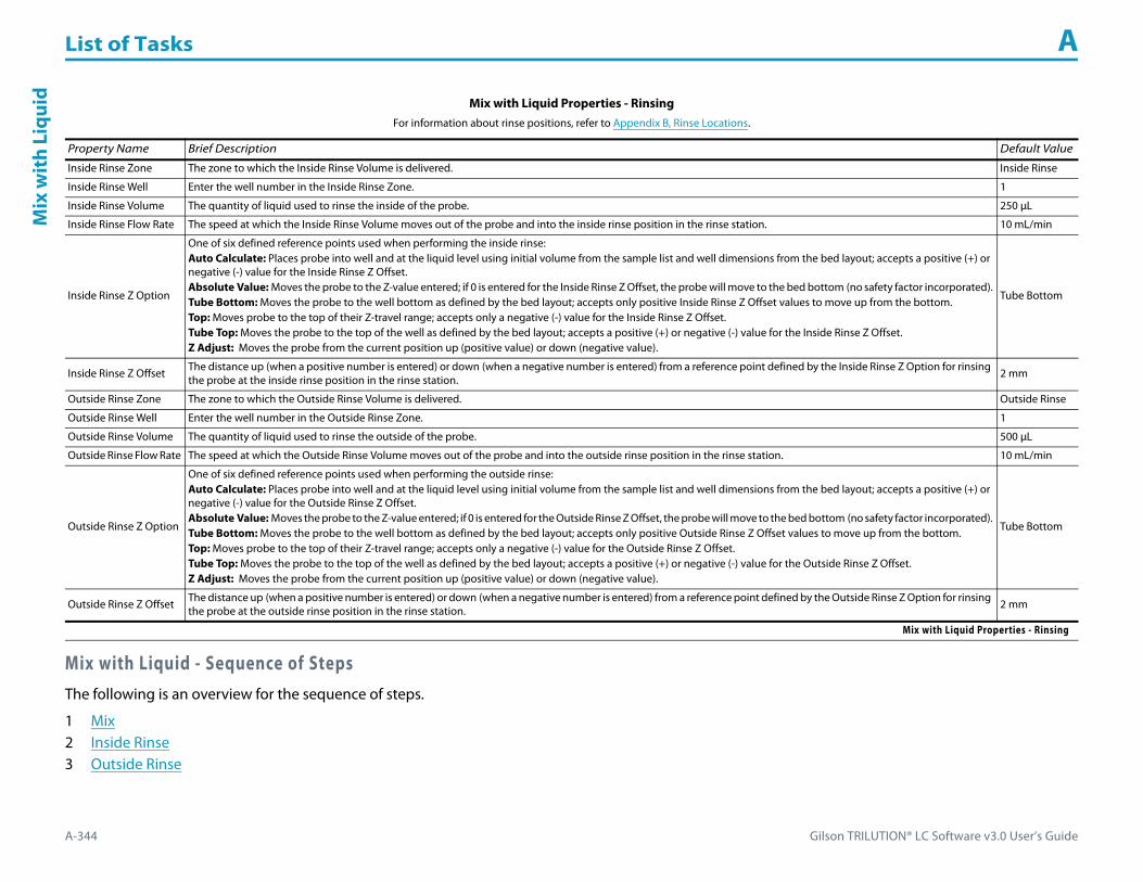
List of Tasks A
A-344 Gilson TRILUTION® LC Software v3.0 User’s Guide
Mix
wit
h Li
quid
Mix with Liquid - Sequence of StepsThe following is an overview for the sequence of steps.
1 Mix2 Inside Rinse3 Outside Rinse
Mix with Liquid Properties - RinsingFor information about rinse positions, refer to Appendix B, Rinse Locations.
Property Name Brief Description Default Value
Inside Rinse Zone The zone to which the Inside Rinse Volume is delivered. Inside Rinse
Inside Rinse Well Enter the well number in the Inside Rinse Zone. 1
Inside Rinse Volume The quantity of liquid used to rinse the inside of the probe. 250 μL
Inside Rinse Flow Rate The speed at which the Inside Rinse Volume moves out of the probe and into the inside rinse position in the rinse station. 10 mL/min
Inside Rinse Z Option
One of six defined reference points used when performing the inside rinse:Auto Calculate: Places probe into well and at the liquid level using initial volume from the sample list and well dimensions from the bed layout; accepts a positive (+) or negative (-) value for the Inside Rinse Z Offset.Absolute Value: Moves the probe to the Z-value entered; if 0 is entered for the Inside Rinse Z Offset, the probe will move to the bed bottom (no safety factor incorporated).Tube Bottom: Moves the probe to the well bottom as defined by the bed layout; accepts only positive Inside Rinse Z Offset values to move up from the bottom.Top: Moves probe to the top of their Z-travel range; accepts only a negative (-) value for the Inside Rinse Z Offset.Tube Top: Moves the probe to the top of the well as defined by the bed layout; accepts a positive (+) or negative (-) value for the Inside Rinse Z Offset.Z Adjust: Moves the probe from the current position up (positive value) or down (negative value).
Tube Bottom
Inside Rinse Z Offset The distance up (when a positive number is entered) or down (when a negative number is entered) from a reference point defined by the Inside Rinse Z Option for rinsing the probe at the inside rinse position in the rinse station. 2 mm
Outside Rinse Zone The zone to which the Outside Rinse Volume is delivered. Outside Rinse
Outside Rinse Well Enter the well number in the Outside Rinse Zone. 1
Outside Rinse Volume The quantity of liquid used to rinse the outside of the probe. 500 μL
Outside Rinse Flow Rate The speed at which the Outside Rinse Volume moves out of the probe and into the outside rinse position in the rinse station. 10 mL/min
Outside Rinse Z Option
One of six defined reference points used when performing the outside rinse:Auto Calculate: Places probe into well and at the liquid level using initial volume from the sample list and well dimensions from the bed layout; accepts a positive (+) or negative (-) value for the Outside Rinse Z Offset.Absolute Value: Moves the probe to the Z-value entered; if 0 is entered for the Outside Rinse Z Offset, the probe will move to the bed bottom (no safety factor incorporated).Tube Bottom: Moves the probe to the well bottom as defined by the bed layout; accepts only positive Outside Rinse Z Offset values to move up from the bottom.Top: Moves probe to the top of their Z-travel range; accepts only a negative (-) value for the Outside Rinse Z Offset.Tube Top: Moves the probe to the top of the well as defined by the bed layout; accepts a positive (+) or negative (-) value for the Outside Rinse Z Offset.Z Adjust: Moves the probe from the current position up (positive value) or down (negative value).
Tube Bottom
Outside Rinse Z Offset The distance up (when a positive number is entered) or down (when a negative number is entered) from a reference point defined by the Outside Rinse Z Option for rinsing the probe at the outside rinse position in the rinse station. 2 mm
Mix with Liquid Properties - Rinsing

Gilson TRILUTION® LC Software v3.0 User’s Guide A-345
List of Tasks AM
ix with Liquid
Mix1 Move Z to Z Safe Height.2 Switch dilutor valve to probe and aspirate Air Gap Volume at Air Gap Flow Rate.3 Move to Mixing Well in Mixing Zone.4 Lower probe to Aspirate Z Option and Aspirate Z Offset. 5 Aspirate Mixing Volume at Aspirate Flow Rate.6 Lower probe to Dispense Z Option and Dispense Z Offset.7 Dispense Mixing Volume at Dispense Flow Rate.8 Repeat steps 4–7 for Number of Cycles.9 Move Z to Z Safe Height.
Inside Rinse1 Move to Inside Rinse Well in Inside Rinse Zone.2 Lower probe into well to Inside Rinse Z Option and Inside Rinse Z Offset.3 Home dilutor.4 Aspirate Inside Rinse Volume or syringe capacity (from Reservoir) at Inside Rinse Flow Rate.5 Dispense Inside Rinse Volume or syringe capacity at Inside Rinse Flow Rate.6 Repeat steps 4–5 until requested rinse volume is aspirated and dispensed.7 Move Z to Z Safe Height.
Outside Rinse1 Move to Outside Rinse Well in Outside Rinse Zone.2 Lower probe into well to Outside Rinse Z Option and Outside Rinse Z Offset.3 Home dilutor.4 Aspirate Outside Rinse Volume or syringe capacity (from Reservoir) at Outside Rinse Flow Rate.5 Dispense Outside Rinse Volume or syringe capacity at Outside Rinse Flow Rate.6 Repeat steps 4–5 until requested rinse volume is aspirated and dispensed.7 Repeat Number of Wells to Mix.

List of Tasks A
A-346 Gilson TRILUTION® LC Software v3.0 User’s Guide
Mov
e to
Sam
ple
Loca
tion Move to Sample Location
This task moves the probe to a specified height in a specified well in a specified zone.
For more information about the task properties, refer to:
Move to Sample Location Properties
Move to Sample Location Properties
Property Name Description Default Value
Liquid Handler The liquid handler that the task will affect. Liquid Handler
Sample Zone The zone to move to. Sample Zone
Sample Well Enter the well number in the Sample Zone. 0
Z Option
One of six defined reference points used when performing the move:Auto Calculate: Places probe into well and at the liquid level using initial volume from the sample list and well dimensions from the bed layout; accepts a positive (+) or negative (-) value for the Z Offset.Absolute Value: Moves the probe to the Z-value entered; if 0 is entered, probe will move to the bed bottom (no safety factor incorporated).Tube Bottom: Moves the probe to the well bottom as defined by the bed layout; accepts only positive Z Offset values to move up from the bottom.Top: Moves probe to the top of their Z-travel range; accepts only a negative (-) value for the Z Offset.Tube Top: Moves the probe to the top of the well as defined by the bed layout; accepts a positive (+) or negative (-) value for the Z Offset.Z Adjust: Moves the probe from the current position up (positive value) or down (negative value).
Tube Bottom
Z Offset The distance up (when a positive number is entered) or down (when a negative number is entered) from a reference point defined by the Z Option. 2 mm
Move to Sample Location Properties

Gilson TRILUTION® LC Software v3.0 User’s Guide A-347
List of Tasks AO
utside Rinse
Outside RinseThis task moves to the rinse station and then rinses the outside of the probe.
For more information about the task properties, refer to:
Outside Rinse Properties
Outside Rinse - Sequence of Steps
Outside Rinse Properties
Property Name Description Default Value
Liquid Handler The liquid handler that the task will affect. Liquid Handler
Pump The pump that the task will affect. Pump
Outside Rinse Zone The zone to which the Rinse Volume is delivered. Outside Rinse
Outside Rinse Well Enter the well number in the Outside Rinse Zone. 1
Rinse Volume The quantity of liquid used to rinse the outside of the probe. 1000 μL
Rinse Flow Rate The speed at which the Rinse Volume moves out of the probe and into the outside rinse position in the rinse station. 3 mL/min
Outside Rinse Properties (Page 1 of 2)
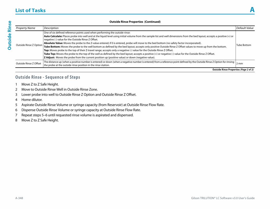
List of Tasks A
A-348 Gilson TRILUTION® LC Software v3.0 User’s Guide
Out
side
Rin
se
Outside Rinse - Sequence of Steps1 Move Z to Z Safe Height.2 Move to Outside Rinse Well in Outside Rinse Zone.3 Lower probe into well to Outside Rinse Z Option and Outside Rinse Z Offset.4 Home dilutor.5 Aspirate Outside Rinse Volume or syringe capacity (from Reservoir) at Outside Rinse Flow Rate.6 Dispense Outside Rinse Volume or syringe capacity at Outside Rinse Flow Rate.7 Repeat steps 5–6 until requested rinse volume is aspirated and dispensed.8 Move Z to Z Safe Height.
Outside Rinse Z Option
One of six defined reference points used when performing the outside rinse:Auto Calculate: Places probe into well and at the liquid level using initial volume from the sample list and well dimensions from the bed layout; accepts a positive (+) or negative (-) value for the Outside Rinse Z Offset.Absolute Value: Moves the probe to the Z-value entered; if 0 is entered, probe will move to the bed bottom (no safety factor incorporated).Tube Bottom: Moves the probe to the well bottom as defined by the bed layout; accepts only positive Outside Rinse Z Offset values to move up from the bottom.Top: Moves probe to the top of their Z-travel range; accepts only a negative (-) value for the Outside Rinse Z Offset.Tube Top: Moves the probe to the top of the well as defined by the bed layout; accepts a positive (+) or negative (-) value for the Outside Rinse Z Offset.Z Adjust: Moves the probe from the current position up (positive value) or down (negative value).
Tube Bottom
Outside Rinse Z Offset The distance up (when a positive number is entered) or down (when a negative number is entered) from a reference point defined by the Outside Rinse Z Option for rinsing the probe at the outside rinse position in the rinse station.
2 mm
Outside Rinse Properties (Continued)
Property Name Description Default Value
Outside Rinse Properties (Page 2 of 2)
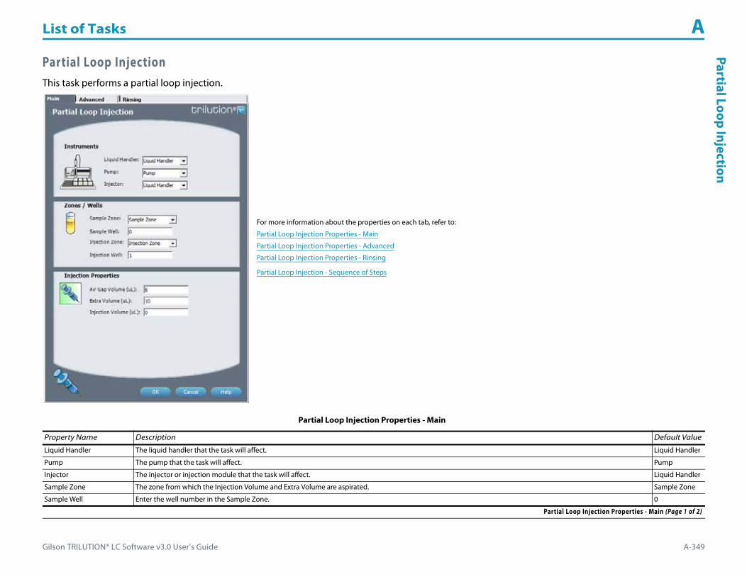
Gilson TRILUTION® LC Software v3.0 User’s Guide A-349
List of Tasks APartial Loop Injection
Partial Loop InjectionThis task performs a partial loop injection.
For more information about the properties on each tab, refer to:
Partial Loop Injection Properties - Main
Partial Loop Injection Properties - Advanced
Partial Loop Injection Properties - Rinsing
Partial Loop Injection - Sequence of Steps
Partial Loop Injection Properties - Main
Property Name Description Default Value
Liquid Handler The liquid handler that the task will affect. Liquid Handler
Pump The pump that the task will affect. Pump
Injector The injector or injection module that the task will affect. Liquid Handler
Sample Zone The zone from which the Injection Volume and Extra Volume are aspirated. Sample Zone
Sample Well Enter the well number in the Sample Zone. 0
Partial Loop Injection Properties - Main (Page 1 of 2)
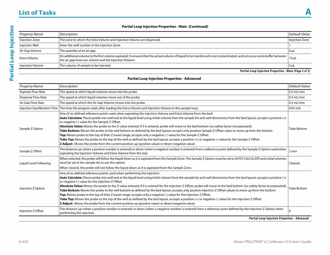
List of Tasks A
A-350 Gilson TRILUTION® LC Software v3.0 User’s Guide
Part
ial L
oop
Inje
ctio
n
Injection Zone The zone to which the Extra Volume and Injection Volume are dispensed. Injection Zone
Injection Well Enter the well number in the Injection Zone. 1
Air Gap Volume The quantity of an air gap. 6 μL
Extra Volume An additional volume to the first volume aspirated. It ensures that the actual volume of liquid to be transferred is not contaminated, and acts as an extra buffer between the air gap/reservoir solvent and the Injection Volume.
10 μL
Injection Volume The volume of sample to be injected. 0 μL
Partial Loop Injection Properties - Advanced
Property Name Description Default Value
Aspirate Flow Rate The speed at which liquid volumes move into the probe. 0.5 mL/min
Dispense Flow Rate The speed at which liquid volumes move out of the probe. 0.5 mL/min
Air Gap Flow Rate The speed at which the Air Gap Volume moves into the probe. 0.3 mL/min
Injection Equilibration Time The time the program waits after loading the Extra Volume and Injection Volume in the sample loop. 0.05 min
Sample Z Option
One of six defined reference points used when aspirating the Injection Volume and Extra Volume from the bed:Auto Calculate: Places probe into well and at the liquid level using initial volume from the sample list and well dimensions from the bed layout; accepts a positive (+) or negative (-) value for the Sample Z Offset.Absolute Value: Moves the probe to the Z-value entered; if 0 is entered, probe will move to the bed bottom (no safety factor incorporated).Tube Bottom: Moves the probe to the well bottom as defined by the bed layout; accepts only positive Sample Z Offset value to move up from the bottom.Top: Moves probe to the top of their Z-travel range; accepts only a negative (-) value for the Sample Z Offset.Tube Top: Moves the probe to the top of the well as defined by the bed layout; accepts a positive (+) or negative (-) value for the Sample Z Offset.Z Adjust: Moves the probe from the current position up (positive value) or down (negative value).
Tube Bottom
Sample Z Offset The distance up (when a positive number is entered) or down (when a negative number is entered) from a reference point defined by the Sample Z Option used when aspirating the Injection Volume and Extra Volume from the bed. 2 mm
Liquid Level FollowingWhen selected, the probe will follow the liquid down as it is aspirated from the Sample Zone. The Sample Z Option must be set to AUTO CALCULATE and initial volumes must be set in the sample list to use this option.
When cleared, the probe will not follow the liquid down as it is aspirated from the Sample Zone.Cleared
Injection Z Option
One of six defined reference points used when performing the injection:Auto Calculate: Places probe into well and at the liquid level using initial volume from the sample list and well dimensions from the bed layout; accepts a positive (+) or negative (-) value for the Injection Z Offset.Absolute Value: Moves the probe to the Z-value entered; if 0 is entered for the Injection Z Offset, probe will move to the bed bottom (no safety factor incorporated).Tube Bottom: Moves the probe to the well bottom as defined by the bed layout; accepts only positive Injection Z Offset values to move up from the bottom.Top: Moves probe to the top of their Z-travel range; accepts only a negative (-) value for the Injection Z Offset.Tube Top: Moves the probe to the top of the well as defined by the bed layout; accepts a positive (+) or negative (-) value for the Injection Z Offset.Z Adjust: Moves the probe from the current position up (positive value) or down (negative value).
Tube Bottom
Injection Z Offset The distance up (when a positive number is entered) or down (when a negative number is entered) from a reference point defined by the Injection Z Option when performing the injection. 0
Partial Loop Injection Properties - Advanced
Partial Loop Injection Properties - Main (Continued)
Property Name Description Default Value
Partial Loop Injection Properties - Main (Page 2 of 2)

Gilson TRILUTION® LC Software v3.0 User’s Guide A-351
List of Tasks APartial Loop Injection
Partial Loop Injection Properties - Rinsing For information about rinse positions, refer to Appendix B, Rinse Locations.
Property Name Description Default Value
Drain Zone The zone in which the dilutor is homed. Inside Rinse
Drain Well Enter the well number in the Drain Zone. 1
Drain Z Option
One of six defined reference points used when purging to the drain:Auto Calculate: Places probe into well and at the liquid level using initial volume from the sample list and well dimensions from the bed layout; accepts a positive (+) or negative (-) value for the Drain Z Offset.Absolute Value: Moves the probe to the Z-value entered; if 0 is entered for the Drain Z Offset, probe will move to the bed bottom (no safety factor incorporated).Tube Bottom: Moves the probe to the well bottom as defined by the bed layout; accepts only positive Drain Z Offset values to move up from the bottom.Top: Moves probe to the top of their Z-travel range; accepts only a negative (-) value for the Drain Z Offset.Tube Top: Moves the probe to the top of the well as defined by the bed layout; accepts a positive (+) or negative (-) value for the Drain Z Offset.Z Adjust: Moves the probe from the current position up (positive value) or down (negative value).
Tube Top
Drain Z Offset The distance up (when a positive number is entered) or down (when a negative number is entered) from a reference point defined by the Drain Z Option for purging to the drain. -7
Injection Rinse Volume The quantity of liquid used to rinse the injection port at Injection Well in Injection Zone. 500 μL
Injection Rinse Flow Rate The speed at which the Injection Rinse Volume moves out of the probe and into the injection port. 4 mL/min
Outside Rinse Zone The zone to which the Outside Rinse Volume is delivered. Outside Rinse
Outside Rinse Well Enter the well number in the Outside Rinse Zone. 1
Outside Rinse Volume The quantity of liquid used to rinse the outside of the probe. 500 μL
Outside Rinse Flow Rate The speed at which the Outside Rinse Volume moves out of the probe and into the outside rinse position in the rinse station. 10 mL/min
Outside Rinse Z Option
One of six defined reference points used when performing the outside rinse:Auto Calculate: Places probe into well and at the liquid level using initial volume from the sample list and well dimensions from the bed layout; accepts a positive (+) or negative (-) value for the Outside Rinse Z Offset.Absolute Value: Moves the probe to the Z-value entered; if 0 is entered, probe will move to the bed bottom (no safety factor incorporated).Tube Bottom: Moves the probe to the well bottom as defined by the bed layout; accepts only positive Outside Rinse Z Offset values to move up from the bottom.Top: Moves probe to the top of their Z-travel range; accepts only a negative (-) value for the Outside Rinse Z Offset.Tube Top: Moves the probe to the top of the well as defined by the bed layout; accepts a positive (+) or negative (-) value for the Outside Rinse Z Offset.Z Adjust: Moves the probe from the current position up (positive value) or down (negative value).
Tube Bottom
Outside Rinse Z Offset The distance up (when a positive number is entered) or down (when a negative number is entered) from a reference point defined by the Outside Rinse Z Option for rinsing the probe at the outside rinse position in the rinse station. 2 mm
Partial Loop Injection Properties - Rinsing

List of Tasks A
A-352 Gilson TRILUTION® LC Software v3.0 User’s Guide
Part
ial L
oop
Inje
ctio
n Partial Loop Injection - Sequence of StepsThe following is an overview for the sequence of steps.
1 Initialize2 Aspirate3 Inject4 Injection Port Rinse5 Outside Rinse
Initialize1 Move Z to Z Safe Height.2 Set injection valve to INJECT.3 Move to Drain Well in Drain Zone.4 Lower probe into well to Drain Z Option and Drain Z Offset.5 Home dilutor.6 Move Z to Z Safe Height.
Aspirate1 Switch dilutor valve to probe and aspirate Air Gap Volume at Air Gap Flow Rate.2 Move to Sample Well in Sample Zone.3 Lower probe into well to Sample Z Option and Sample Z Offset.4 Switch dilutor valve to probe and aspirate Injection Volume + Extra Volume at Aspirate Flow Rate.5 Move Z to Z Safe Height.
Inject1 Move to Injection Well in Injection Zone.2 Lower probe into well to Injection Z Option and Injection Z Offset.3 Dispense Extra Volume at Dispense Flow Rate.4 Switch injection valve to LOAD.5 Wait 1.2 sec.6 Dispense Injection Volume at Dispense Flow Rate.7 Wait Injection Equilibration Time.8 Synchronize.9 Switch injection valve to INJECT.

Gilson TRILUTION® LC Software v3.0 User’s Guide A-353
List of Tasks APartial Loop Injection
Injection Port Rinse1 Home dilutor.2 Switch dilutor valve to reservoir.3 Aspirate Injection Rinse Volume or syringe capacity at Injection Rinse Flow Rate.4 Switch dilutor valve to probe.5 Dispense Injection Rinse Volume or syringe capacity at Injection Rinse Flow Rate.6 Repeat steps 2–5 until requested rinse volume is aspirated and dispensed.7 Move Z to Z Safe Height.
Outside Rinse1 Move to Outside Rinse Well in Outside Rinse Zone.2 Lower probe into well to Outside Rinse Z Option and Outside Rinse Z Offset.3 Home dilutor.4 Switch dilutor valve to reservoir.5 Aspirate Outside Rinse Volume or syringe capacity at Outside Rinse Flow Rate.6 Switch dilutor valve to probe.7 Dispense Outside Rinse Volume or syringe capacity at Outside Rinse Flow Rate.8 Repeat steps 4–7 until requested rinse volume is aspirated and dispensed.

List of Tasks A
A-354 Gilson TRILUTION® LC Software v3.0 User’s Guide
Prep
Inje
ctio
n w
ith
Colle
ctio
n Prep Injection with CollectionThis task is used when doing injection and fraction collection on the same bed. It performs a partial loop injection using a push volume from the reservoir to push the injection volume into the sample loop and includes a rinse of the fraction collection valve.
For more information about the properties on each tab, refer to:
Prep Injection with Collection Properties - Main
Prep Injection with Collection Properties - Advanced
Prep Injection with Collection Properties - Rinsing
Prep Injection with Collection - Sequence of Steps
Prep Injection with Collection Properties - Main
Property Name Description Default Value
Liquid Handler The liquid handler that the task will affect. Liquid Handler
Pump The pump that the task will affect. Pump
Injector The injector or injection module that the task will affect. Liquid Handler
Sample Zone The zone from which the Injection Volume is aspirated. Sample Zone
Prep Injection with Collection Properties - Main (Page 1 of 2)

Gilson TRILUTION® LC Software v3.0 User’s Guide A-355
List of Tasks APrep Injection w
ith Collection
Sample Well Enter the well number in the Sample Zone. 0
Injection Zone The zone to which the Injection Volume and Push Volume are dispensed. Injection Zone
Injection Well Enter the well number in the Injection Zone. 1
Air Gap Volume The quantity of an air gap. 6 μL
Push Volume A volume of reservoir solvent used to push the injection volume into the sample loop. 10 μL
Injection Volume The volume of sample to be injected. 0 μL
Prep Injection with Collection Properties - Advanced
Property Name Description Default Value
Aspirate Flow Rate The speed at which liquid volumes move into the probe. 3 mL/min
Dispense Flow Rate The speed at which liquid volumes move out of the probe. 3 mL/min
Air Gap Flow Rate The speed at which the Air Gap Volume moves into the probe. 0.3 mL/min
Injection Equilibration Time The time the program waits after loading the Extra Volume, Injection Volume, and Push Volume in the sample loop. 0.05 min
Sample Z Option
One of six defined reference points used when aspirating the Injection Volume and Extra Volume from the bed:Auto Calculate: Places probe into well and at the liquid level using initial volume from the sample list and well dimensions from the bed layout; accepts a positive (+) or negative (-) value for the Sample Z Offset.Absolute Value: Moves the probe to the Z-value entered; if 0 is entered, probe will move to the bed bottom (no safety factor incorporated).Tube Bottom: Moves the probe to the well bottom as defined by the bed layout; accepts only positive Sample Z Offset value to move up from the bottom.Top: Moves probe to the top of their Z-travel range; accepts only a negative (-) value for the Sample Z Offset.Tube Top: Moves the probe to the top of the well as defined by the bed layout; accepts a positive (+) or negative (-) value for the Sample Z Offset.Z Adjust: Moves the probe from the current position up (positive value) or down (negative value).
Tube Bottom
Sample Z Offset The distance up (when a positive number is entered) or down (when a negative number is entered) from a reference point defined by the Sample Z Option used when aspirating the Injection Volume and Extra Volume from the bed. 2 mm
Liquid Level FollowingWhen selected, the probe will follow the liquid down as it is aspirated from the Sample Zone. The Sample Z Option must be set to AUTO CALCULATE and initial volumes must be set in the sample list to use this option.
When cleared, the probe will not follow the liquid down as it is aspirated from the Sample Zone.Cleared
Injection Z Option
One of six defined reference points used when performing the injection:Auto Calculate: Places probe into well and at the liquid level using initial volume from the sample list and well dimensions from the bed layout; accepts a positive (+) or negative (-) value for the Injection Z Offset.Absolute Value: Moves the probe to the Z-value entered; if 0 is entered for the Injection Z Offset, probe will move to the bed bottom (no safety factor incorporated).Tube Bottom: Moves the probe to the well bottom as defined by the bed layout; accepts only positive Injection Z Offset values to move up from the bottom.Top: Moves probe to the top of their Z-travel range; accepts only a negative (-) value for the Injection Z Offset.Tube Top: Moves the probe to the top of the well as defined by the bed layout; accepts a positive (+) or negative (-) value for the Injection Z Offset.Z Adjust: Moves the probe from the current position up (positive value) or down (negative value).
Tube Bottom
Injection Z Offset The distance up (when a positive number is entered) or down (when a negative number is entered) from a reference point defined by the Injection Z Option when performing the injection. 0
Prep Injection with Collection Properties - Advanced
Prep Injection with Collection Properties - Main (Continued)
Property Name Description Default Value
Prep Injection with Collection Properties - Main (Page 2 of 2)
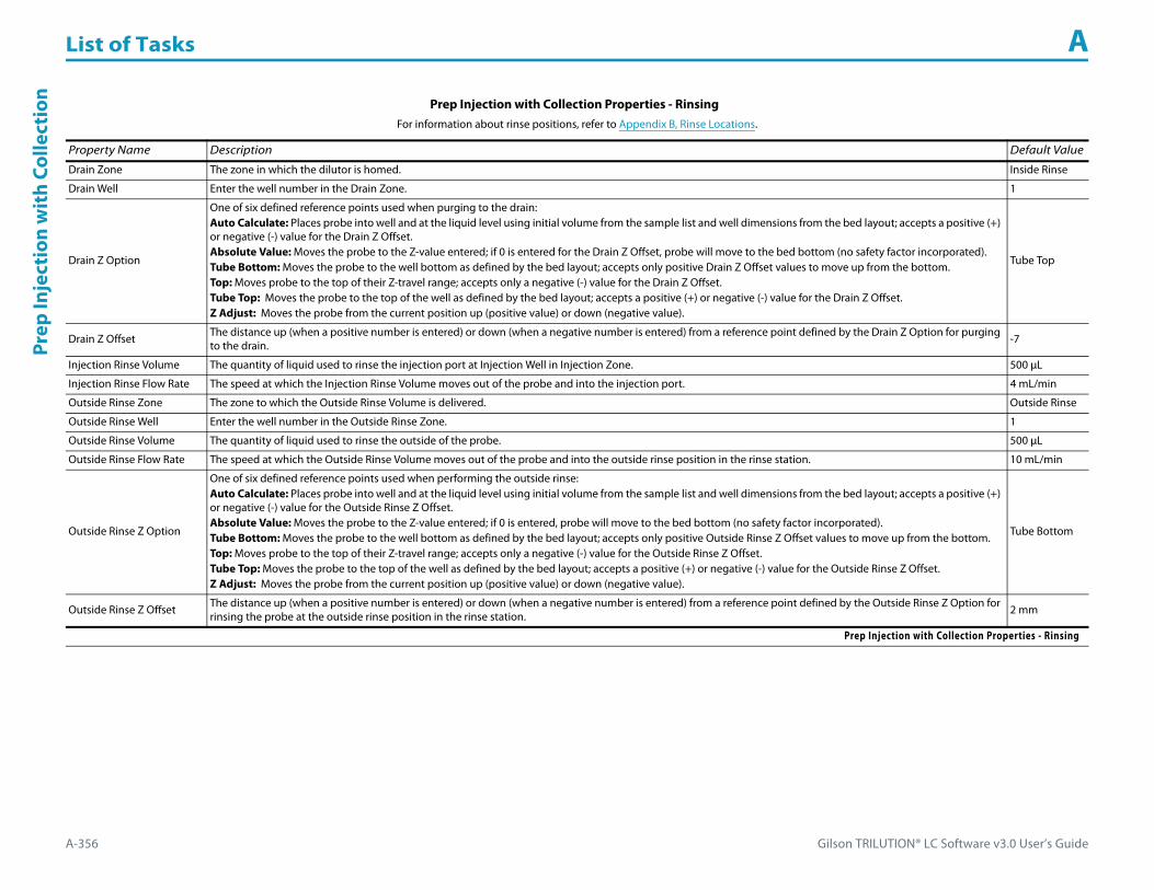
List of Tasks A
A-356 Gilson TRILUTION® LC Software v3.0 User’s Guide
Prep
Inje
ctio
n w
ith
Colle
ctio
n
Prep Injection with Collection Properties - Rinsing For information about rinse positions, refer to Appendix B, Rinse Locations.
Property Name Description Default Value
Drain Zone The zone in which the dilutor is homed. Inside Rinse
Drain Well Enter the well number in the Drain Zone. 1
Drain Z Option
One of six defined reference points used when purging to the drain:Auto Calculate: Places probe into well and at the liquid level using initial volume from the sample list and well dimensions from the bed layout; accepts a positive (+) or negative (-) value for the Drain Z Offset.Absolute Value: Moves the probe to the Z-value entered; if 0 is entered for the Drain Z Offset, probe will move to the bed bottom (no safety factor incorporated).Tube Bottom: Moves the probe to the well bottom as defined by the bed layout; accepts only positive Drain Z Offset values to move up from the bottom.Top: Moves probe to the top of their Z-travel range; accepts only a negative (-) value for the Drain Z Offset.Tube Top: Moves the probe to the top of the well as defined by the bed layout; accepts a positive (+) or negative (-) value for the Drain Z Offset.Z Adjust: Moves the probe from the current position up (positive value) or down (negative value).
Tube Top
Drain Z Offset The distance up (when a positive number is entered) or down (when a negative number is entered) from a reference point defined by the Drain Z Option for purging to the drain. -7
Injection Rinse Volume The quantity of liquid used to rinse the injection port at Injection Well in Injection Zone. 500 μL
Injection Rinse Flow Rate The speed at which the Injection Rinse Volume moves out of the probe and into the injection port. 4 mL/min
Outside Rinse Zone The zone to which the Outside Rinse Volume is delivered. Outside Rinse
Outside Rinse Well Enter the well number in the Outside Rinse Zone. 1
Outside Rinse Volume The quantity of liquid used to rinse the outside of the probe. 500 μL
Outside Rinse Flow Rate The speed at which the Outside Rinse Volume moves out of the probe and into the outside rinse position in the rinse station. 10 mL/min
Outside Rinse Z Option
One of six defined reference points used when performing the outside rinse:Auto Calculate: Places probe into well and at the liquid level using initial volume from the sample list and well dimensions from the bed layout; accepts a positive (+) or negative (-) value for the Outside Rinse Z Offset.Absolute Value: Moves the probe to the Z-value entered; if 0 is entered, probe will move to the bed bottom (no safety factor incorporated).Tube Bottom: Moves the probe to the well bottom as defined by the bed layout; accepts only positive Outside Rinse Z Offset values to move up from the bottom.Top: Moves probe to the top of their Z-travel range; accepts only a negative (-) value for the Outside Rinse Z Offset.Tube Top: Moves the probe to the top of the well as defined by the bed layout; accepts a positive (+) or negative (-) value for the Outside Rinse Z Offset.Z Adjust: Moves the probe from the current position up (positive value) or down (negative value).
Tube Bottom
Outside Rinse Z Offset The distance up (when a positive number is entered) or down (when a negative number is entered) from a reference point defined by the Outside Rinse Z Option for rinsing the probe at the outside rinse position in the rinse station. 2 mm
Prep Injection with Collection Properties - Rinsing
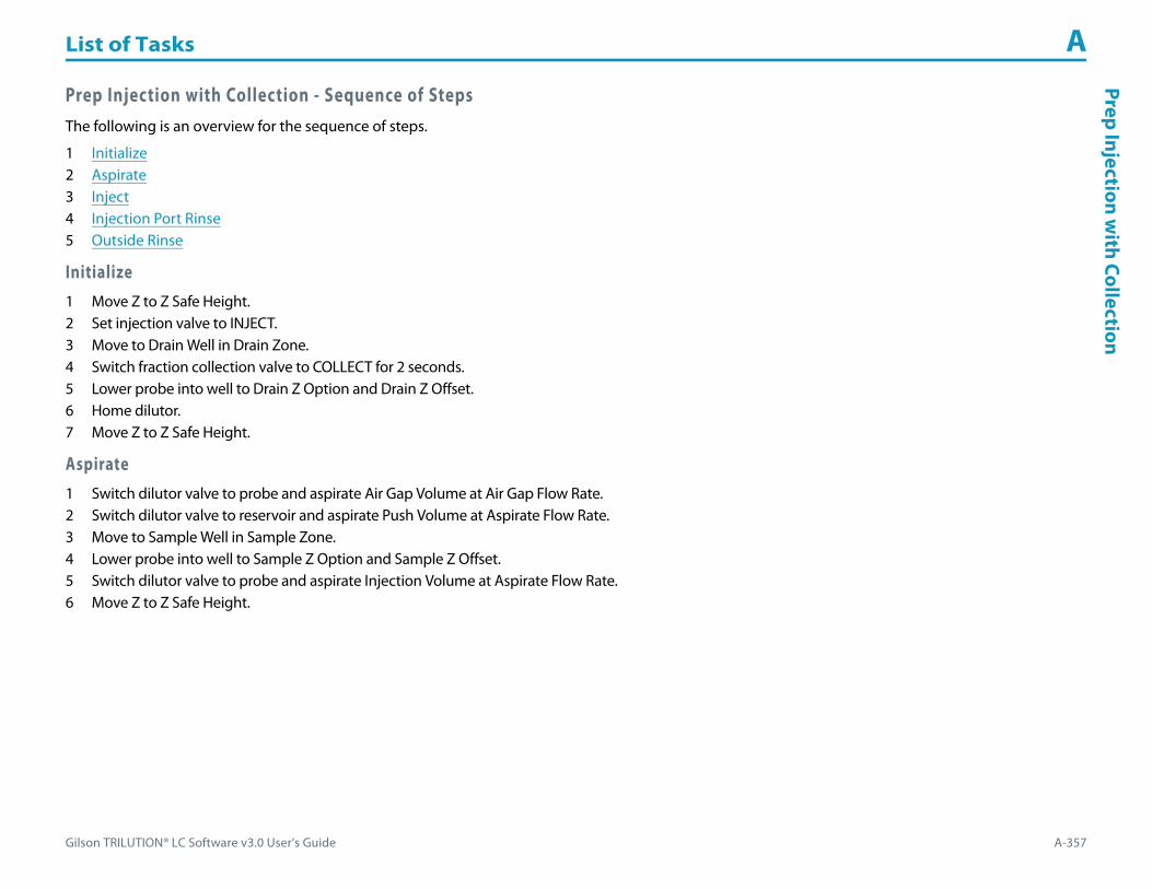
Gilson TRILUTION® LC Software v3.0 User’s Guide A-357
List of Tasks APrep Injection w
ith Collection
Prep Injection with Collection - Sequence of StepsThe following is an overview for the sequence of steps.
1 Initialize2 Aspirate3 Inject4 Injection Port Rinse5 Outside Rinse
Initialize1 Move Z to Z Safe Height.2 Set injection valve to INJECT.3 Move to Drain Well in Drain Zone.4 Switch fraction collection valve to COLLECT for 2 seconds.5 Lower probe into well to Drain Z Option and Drain Z Offset.6 Home dilutor.7 Move Z to Z Safe Height.
Aspirate1 Switch dilutor valve to probe and aspirate Air Gap Volume at Air Gap Flow Rate.2 Switch dilutor valve to reservoir and aspirate Push Volume at Aspirate Flow Rate.3 Move to Sample Well in Sample Zone.4 Lower probe into well to Sample Z Option and Sample Z Offset.5 Switch dilutor valve to probe and aspirate Injection Volume at Aspirate Flow Rate.6 Move Z to Z Safe Height.

List of Tasks A
A-358 Gilson TRILUTION® LC Software v3.0 User’s Guide
Prep
Inje
ctio
n w
ith
Colle
ctio
n Inject1 Move to Injection Well in Injection Zone.2 Lower probe into well to Injection Z Option and Injection Z Offset.3 Switch injection valve to LOAD.4 Wait 1.2 sec.5 Dispense Injection Volume + Push Volume at Dispense Flow Rate.6 Wait Injection Equilibration Time.7 Synchronize.8 Switch injection valve to INJECT.
Injection Port Rinse1 Home dilutor.2 Switch dilutor valve to reservoir.3 Aspirate Injection Rinse Volume or syringe capacity at Injection Rinse Flow Rate.4 Switch dilutor valve to probe.5 Dispense Injection Rinse Volume or syringe capacity at Injection Rinse Flow Rate.6 Repeat steps 2–5 until requested rinse volume is aspirated and dispensed.7 Move Z to Z Safe Height.
Outside Rinse1 Move to Outside Rinse Well in Outside Rinse Zone.2 Lower probe into well to Outside Rinse Z Option and Outside Rinse Z Offset.3 Home dilutor.4 Switch dilutor valve to reservoir.5 Aspirate Outside Rinse Volume or syringe capacity at Outside Rinse Flow Rate.6 Switch dilutor valve to probe.7 Dispense Outside Rinse Volume or syringe capacity at Outside Rinse Flow Rate.8 Repeat steps 4–7 until requested rinse volume is aspirated and dispensed.

Gilson TRILUTION® LC Software v3.0 User’s Guide A-359
List of Tasks APrep Injection w
ith Collection High M
ount
Prep Injection with Collection High MountThis task is used when doing injection and fraction collection on the same bed. It performs a partial loop injection using a push volume from the reservoir to push the injection volume into the sample loop and includes a rinse of the fraction collection valve for a user-defined duration.
For more information about the properties on each tab, refer to:
Prep Injection with Collection High Mount Properties - Main
Prep Injection with Collection High Mount Properties - Rinsing
Prep Injection with Collection High Mount - Sequence of Steps
Prep Injection with Collection High Mount Properties - Main
Property Name Description Default Value
Liquid Handler The liquid handler that the task will affect. Liquid Handler
Pump The pump that the task will affect. Pump
Injector The injector or injection module that the task will affect. Liquid Handler
Sample Zone The zone from which the Injection Volume is aspirated. Sample Zone
Sample Well Enter the well number in the Sample Zone. 0
Injection Zone The zone to which the Injection Volume and Push Volume are dispensed. Injection Zone
Prep Injection with Collection High Mount Properties - Main (Page 1 of 2)

List of Tasks A
A-360 Gilson TRILUTION® LC Software v3.0 User’s Guide
Prep
Inje
ctio
n w
ith
Colle
ctio
n H
igh
Mou
nt
Injection Well Enter the well number in the Injection Zone. 1
Air Gap Volume The quantity of an air gap. 6 μL
Push Volume A volume of reservoir solvent used to push the injection volume into the sample loop. 10 μL
Injection Volume The volume of sample to be injected. 0 μL
Aspirate Flow Rate The speed at which liquid volumes move into the probe. 3 mL/min
Dispense Flow Rate The speed at which liquid volumes move out of the probe. 3 mL/min
Air Gap Flow Rate The speed at which the Air Gap Volume moves into the probe. 0.3 mL/min
Injection Equilibration Time The time the program waits after loading the Extra Volume, Injection Volume, and Push Volume in the sample loop. 0.05 min
Sample Z Option
One of six defined reference points used when aspirating the Injection Volume and Extra Volume from the bed:Auto Calculate: Places probe into well and at the liquid level using initial volume from the sample list and well dimensions from the bed layout; accepts a positive (+) or negative (-) value for the Sample Z Offset.Absolute Value: Moves the probe to the Z-value entered; if 0 is entered, probe will move to the bed bottom (no safety factor incorporated).Tube Bottom: Moves the probe to the well bottom as defined by the bed layout; accepts only positive Sample Z Offset value to move up from the bottom.Top: Moves probe to the top of their Z-travel range; accepts only a negative (-) value for the Sample Z Offset.Tube Top: Moves the probe to the top of the well as defined by the bed layout; accepts a positive (+) or negative (-) value for the Sample Z Offset.Z Adjust: Moves the probe from the current position up (positive value) or down (negative value).
Tube Bottom
Sample Z Offset The distance up (when a positive number is entered) or down (when a negative number is entered) from a reference point defined by the Sample Z Option used when aspirating the Injection Volume and Extra Volume from the bed. 2 mm
Liquid Level FollowingWhen selected, the probe will follow the liquid down as it is aspirated from the Sample Zone. The Sample Z Option must be set to AUTO CALCULATE and initial volumes must be set in the sample list to use this option.
When cleared, the probe will not follow the liquid down as it is aspirated from the Sample Zone.Cleared
Injection Z Option
One of six defined reference points used when performing the injection:Auto Calculate: Places probe into well and at the liquid level using initial volume from the sample list and well dimensions from the bed layout; accepts a positive (+) or negative (-) value for the Injection Z Offset.Absolute Value: Moves the probe to the Z-value entered; if 0 is entered for the Injection Z Offset, probe will move to the bed bottom (no safety factor incorporated).Tube Bottom: Moves the probe to the well bottom as defined by the bed layout; accepts only positive Injection Z Offset values to move up from the bottom.Top: Moves probe to the top of their Z-travel range; accepts only a negative (-) value for the Injection Z Offset.Tube Top: Moves the probe to the top of the well as defined by the bed layout; accepts a positive (+) or negative (-) value for the Injection Z Offset.Z Adjust: Moves the probe from the current position up (positive value) or down (negative value).
Tube Bottom
Injection Z Offset The distance up (when a positive number is entered) or down (when a negative number is entered) from a reference point defined by the Injection Z Option when performing the injection. 0
Prep Injection with Collection High Mount Properties - Rinsing For information about rinse positions, refer to Appendix B, Rinse Locations.
Property Name Description Default Value
Inside Rinse Zone The zone to which the Rinse Volume is delivered. Inside Rinse
Inside Rinse Well Enter the well number in the Inside Rinse Zone. 1
Rinse Volume The quantity of liquid used to rinse the inside of the probe. 1000 μL
Prep Injection with Collection High Mount Properties - Rinsing (Page 1 of 3)
Prep Injection with Collection High Mount Properties - Main (Continued)
Property Name Description Default Value
Prep Injection with Collection High Mount Properties - Main (Page 2 of 2)

Gilson TRILUTION® LC Software v3.0 User’s Guide A-361
List of Tasks APrep Injection w
ith Collection High M
ount
Rinse Flow Rate The speed at which the Rinse Volume moves out of the probe and into the outside rinse position in the rinse station. 5 mL/min
Inside Rinse Z Option
One of six defined reference points used when performing the inside rinse:Auto Calculate: Places probe into well and at the liquid level using initial volume from the sample list and well dimensions from the bed layout; accepts a positive (+) or negative (-) value for the Inside Rinse Z Offset.Absolute Value: Moves the probe to the Z-value entered; if 0 is entered for the Inside Rinse Z Offset, the probe will move to the bed bottom (no safety factor incorporated).Tube Bottom: Moves the probe to the well bottom as defined by the bed layout; accepts only positive Inside Rinse Z Offset values to move up from the bottom.Top: Moves probe to the top of their Z-travel range; accepts only a negative (-) value for the Inside Rinse Z Offset.Tube Top: Moves the probe to the top of the well as defined by the bed layout; accepts a positive (+) or negative (-) value for the Inside Rinse Z Offset.Z Adjust: Moves the probe from the current position up (positive value) or down (negative value).
Tube Top
Inside Rinse Z Offset The distance up (when a positive number is entered) or down (when a negative number is entered) from a reference point defined by the Inside Rinse Z Option for rinsing the probe at the inside rinse position in the rinse station. -7 mm
Drain Zone The zone in which the dilutor is homed. Inside Rinse
Drain Well Enter the well number in the Drain Zone. 1
Drain Z Option
One of six defined reference points used when purging to the drain:Auto Calculate: Places probe into well and at the liquid level using initial volume from the sample list and well dimensions from the bed layout; accepts a positive (+) or negative (-) value for the Drain Z Offset.Absolute Value: Moves the probe to the Z-value entered; if 0 is entered for the Drain Z Offset, probe will move to the bed bottom (no safety factor incorporated).Tube Bottom: Moves the probe to the well bottom as defined by the bed layout; accepts only positive Drain Z Offset values to move up from the bottom.Top: Moves probe to the top of their Z-travel range; accepts only a negative (-) value for the Drain Z Offset.Tube Top: Moves the probe to the top of the well as defined by the bed layout; accepts a positive (+) or negative (-) value for the Drain Z Offset.Z Adjust: Moves the probe from the current position up (positive value) or down (negative value).
Tube Top
Drain Z Offset The distance up (when a positive number is entered) or down (when a negative number is entered) from a reference point defined by the Drain Z Option for purging to the drain. -7
Fraction Collection Valve Rinse Time After the valve switches to COLLECT, the length of time the valve is rinsed before switching the valve back to DIVERT. 0.1 min
Injection Rinse Volume The quantity of liquid used to rinse the injection port at Injection Well in Injection Zone. 500 μL
Injection Rinse Flow Rate The speed at which the Injection Rinse Volume moves out of the probe and into the injection port. 4 mL/min
Outside Rinse Zone The zone to which the Outside Rinse Volume is delivered. Outside Rinse
Outside Rinse Well Enter the well number in the Outside Rinse Zone. 1
Outside Rinse Volume The quantity of liquid used to rinse the outside of the probe. 500 μL
Outside Rinse Flow Rate The speed at which the Outside Rinse Volume moves out of the probe and into the outside rinse position in the rinse station. 10 mL/min
Prep Injection with Collection High Mount Properties - Rinsing (Continued)For information about rinse positions, refer to Appendix B, Rinse Locations.
Property Name Description Default Value
Prep Injection with Collection High Mount Properties - Rinsing (Page 2 of 3)

List of Tasks A
A-362 Gilson TRILUTION® LC Software v3.0 User’s Guide
Prep
Inje
ctio
n w
ith
Colle
ctio
n H
igh
Mou
nt
Prep Injection with Collection High Mount - Sequence of StepsThe following is an overview for the sequence of steps.
1 Initialize2 Aspirate3 Inject4 Injection Port Rinse5 Outside Rinse6 Fraction Collection Valve Flush
Initialize1 Move Z to Z Safe Height.2 Set injection valve to INJECT.3 Move Z to Z Safe Height.4 Move to Inside Rinse Well in Inside Rinse Zone.5 Lower probe into well to Inside Rinse Z Option and Inside Rinse Z Offset.6 Switch solvent valve to Solvent Valve Position and dispense volume held by transfer tubing at Rinse Flow Rate.7 Dispense Rinse Volume at Rinse Flow Rate.8 Move Z to Z Safe Height.
Outside Rinse Z Option
One of six defined reference points used when performing the outside rinse:Auto Calculate: Places probe into well and at the liquid level using initial volume from the sample list and well dimensions from the bed layout; accepts a positive (+) or negative (-) value for the Outside Rinse Z Offset.Absolute Value: Moves the probe to the Z-value entered; if 0 is entered, probe will move to the bed bottom (no safety factor incorporated).Tube Bottom: Moves the probe to the well bottom as defined by the bed layout; accepts only positive Outside Rinse Z Offset values to move up from the bottom.Top: Moves probe to the top of their Z-travel range; accepts only a negative (-) value for the Outside Rinse Z Offset.Tube Top: Moves the probe to the top of the well as defined by the bed layout; accepts a positive (+) or negative (-) value for the Outside Rinse Z Offset.Z Adjust: Moves the probe from the current position up (positive value) or down (negative value).
Tube Bottom
Outside Rinse Z Offset The distance up (when a positive number is entered) or down (when a negative number is entered) from a reference point defined by the Outside Rinse Z Option for rinsing the probe at the outside rinse position in the rinse station. 2 mm
Prep Injection with Collection High Mount Properties - Rinsing (Continued)For information about rinse positions, refer to Appendix B, Rinse Locations.
Property Name Description Default Value
Prep Injection with Collection High Mount Properties - Rinsing (Page 3 of 3)

Gilson TRILUTION® LC Software v3.0 User’s Guide A-363
List of Tasks APrep Injection w
ith Collection High M
ount
Aspirate1 Switch dilutor valve to probe and aspirate Air Gap Volume at Air Gap Flow Rate.2 Switch dilutor valve to reservoir and aspirate Push Volume at Aspirate Flow Rate.3 Move to Sample Well in Sample Zone.4 Lower probe into well to Sample Z Option and Sample Z Offset.5 Switch dilutor valve to probe and aspirate Injection Volume at Aspirate Flow Rate.6 Move Z to Z Safe Height.
Inject1 Move to Injection Well in Injection Zone.2 Lower probe into well to Injection Z Option and Injection Z Offset.3 Switch injection valve to LOAD.4 Wait 1.2 sec.5 Dispense Injection Volume + Push Volume at Dispense Flow Rate.6 Wait Injection Equilibration Time.7 Synchronize.8 Switch injection valve to INJECT.
Injection Port Rinse1 Home dilutor.2 Switch dilutor valve to reservoir.3 Aspirate Injection Rinse Volume or syringe capacity at Injection Rinse Flow Rate.4 Switch dilutor valve to probe.5 Dispense Injection Rinse Volume or syringe capacity at Injection Rinse Flow Rate.6 Repeat steps 2–5 until requested rinse volume is aspirated and dispensed.7 Move Z to Z Safe Height.

List of Tasks A
A-364 Gilson TRILUTION® LC Software v3.0 User’s Guide
Prep
Inje
ctio
n w
ith
Colle
ctio
n H
igh
Mou
nt Outside Rinse1 Move to Outside Rinse Well in Outside Rinse Zone.2 Lower probe into well to Outside Rinse Z Option and Outside Rinse Z Offset.3 Home dilutor.4 Switch dilutor valve to reservoir.5 Aspirate Outside Rinse Volume or syringe capacity at Outside Rinse Flow Rate.6 Switch dilutor valve to probe.7 Dispense Outside Rinse Volume or syringe capacity at Outside Rinse Flow Rate.8 Repeat steps 4–7 until requested rinse volume is aspirated and dispensed.
Fraction Collection Valve Flush1 Move Z to Z Safe Height.2 Move to Drain Well in Drain Zone.3 Lower probe into well to Drain Z Option and Drain Z Offset.4 Switch fraction collection valve to COLLECT for Fraction Collection Valve Rinse Time then switch the fraction collection valve to DIVERT.5 Move Z to Z Safe Height.

Gilson TRILUTION® LC Software v3.0 User’s Guide A-365
List of Tasks APrim
e Dilutor
Prime DilutorThis task primes the dilutor. It aspirates the syringe capacity from the reservoir and then dispenses to the specified wells in the specified zone for the number of cycles.
For more information about the properties on each tab, refer to:
Prime Dilutor Properties
Prime Dilutor - Sequence of Steps
Prime Dilutor Properties
Property Name Description Default Value
Liquid Handler The liquid handler that the task will affect. Liquid Handler
Pump The pump that the task will affect. Pump
Number of Cycles Enter the number of times to repeat aspirating and dispensing. 4
Flow Rate The speed at which the solvent moves into the syringe and then out of the probe. 10 mL/min
Rinse Zone The zone to which the volume is dispensed. Inside Rinse
Rinse Well Enter the well number in the Rinse Zone. 1
Prime Dilutor Properties (Page 1 of 2)

List of Tasks A
A-366 Gilson TRILUTION® LC Software v3.0 User’s Guide
Prim
e D
iluto
r
Prime Dilutor - Sequence of Steps1 Move Z to Z Safe Height2 Move probe to Rinse Well in Rinse Zone.3 Lower probe to Z Option and Z Offset.4 Home dilutor.5 Aspirate full syringe capacity (from Reservoir) at Flow Rate.6 Dispense full syringe capacity at Flow Rate.7 Repeat steps 5–6 for Number of Cycles.8 Move Z to Z Safe Height.
Z Option
One of six defined reference points used when delivering liquids to the rinse station:Auto Calculate: Places probe into well and at the liquid level using initial volume from the sample list and well dimensions from the bed layout; accepts a positive (+) or negative (-) value for the Z Offset.Absolute Value: Moves the probe to the Z-value entered; if 0 is entered, probe will move to the bed bottom (no safety factor incorporated).Tube Bottom: Moves the probe to the well bottom as defined by the bed layout; accepts only positive Z Offset value to move up from the bottom.Top: Moves probe to the top of their Z-travel range; accepts only a negative (-) value for the Z Offset.Tube Top: Moves the probe to the top of the well as defined by the bed layout; accepts a positive (+) or negative (-) value for the Z Offset.Z Adjust: Moves the probe from the current position up (positive value) or down (negative value).
Tube Bottom
Z Offset The distance up (when a positive number is entered) or down (when a negative number is entered) from a reference point defined by the Z Option for delivering liquids to the rinse station.
2 mm
Prime Dilutor Properties (Continued)
Property Name Description Default Value
Prime Dilutor Properties (Page 2 of 2)

Gilson TRILUTION® LC Software v3.0 User’s Guide A-367
List of Tasks AProm
pt
PromptThis task displays a prompt dialog with the selected message.
For more information about the task properties, refer to:
Prompt Properties
Prompt Properties
Property Name Description Default Value
Message Enter the text to display in the message box. Message
Prompt Properties

List of Tasks A
A-368 Gilson TRILUTION® LC Software v3.0 User’s Guide
Set D
etec
tor M
ode Set Detector Mode
This task sets the detection mode on a 155 or 156 UV/VIS Detector.
For more information about the task properties, refer to:
Set Detector Mode Properties
Set Detector Mode Properties
Property Name Description Default Value
Detector The detector that the task will affect. Detector
Mode Select from DUAL, SCAN, or SINGLE. DUAL
Set Detector Mode Properties

Gilson TRILUTION® LC Software v3.0 User’s Guide A-369
List of Tasks ASet Fraction Site
Set Fraction SiteThis task identifies where fraction collection will begin for an injected sample.
For more information about the task properties, refer to:
Set Fraction Site Properties
Set Fraction Site Properties
Property Name Description Default Value
Fraction Collector The fraction collector that the task will affect. Fraction Collector
Fraction Zone The zone in which fractions are collected. Fraction Zone
Fraction Well Enter the well number in the Fraction Zone in which collection will begin. The default of 0 is for continuous collection and the fractions are always collected in the next available tube. 0
Set Fraction Site Properties

List of Tasks A
A-370 Gilson TRILUTION® LC Software v3.0 User’s Guide
Set M
ulti
ple
Bed
Colle
ctio
n Set Multiple Bed CollectionThis task is used to set the fraction site when multiple fraction collectors are being used.
For more information about the task properties, refer to:
Set Multiple Bed Collection Properties
Set Multiple Bed Collection Properties
Property Name Description Default Value
Fraction Site 1Fraction Collector
The first fraction collector that the task will affect. Fraction Collector
Fraction Site 1Fraction Zone
The zone in which fractions are collected on the first fraction collector. Fraction Zone
Fraction Site 1Fraction Well
Enter the well number in the Fraction Zone in which collection will begin on the first fraction collector. The default of 0 is for continuous collection and the fractions are always collected in the next available tube. 0
Fraction Site 2Fraction Collector
The second fraction collector that the task will affect. Fraction Collector
Set Multiple Bed Collection Properties (Page 1 of 2)

Gilson TRILUTION® LC Software v3.0 User’s Guide A-371
List of Tasks ASet M
ultiple Bed Collection
Fraction Site 2Fraction Zone
The zone in which fractions are collected on the second fraction collector. Fraction Zone
Fraction Site 2Fraction Well
Enter the well number in the Fraction Zone in which collection will begin on the second fraction collector. The default of 0 is for continuous collection and the fractions are always collected in the next available tube. 0
Fraction Site 3Fraction Collector
The third fraction collector that the task will affect. Fraction Collector
Fraction Site 3Fraction Zone
The zone in which fractions are collected on the third fraction collector. Fraction Zone
Fraction Site 3Fraction Well
Enter the well number in the Fraction Zone in which collection will begin on the third fraction collector. The default of 0 is for continuous collection and the fractions are always collected in the next available tube. 0
Fraction Site 4Fraction Collector
The fourth fraction collector that the task will affect. Fraction Collector
Fraction Site 4Fraction Zone
The zone in which fractions are collected on the fourth fraction collector. Fraction Zone
Fraction Site 4Fraction Well
Enter the well number in the Fraction Zone in which collection will begin on the fourth fraction collector. The default of 0 is for continuous collection and the fractions are always collected in the next available tube. 0
Set Multiple Bed Collection Properties (Continued)
Property Name Description Default Value
Set Multiple Bed Collection Properties (Page 2 of 2)
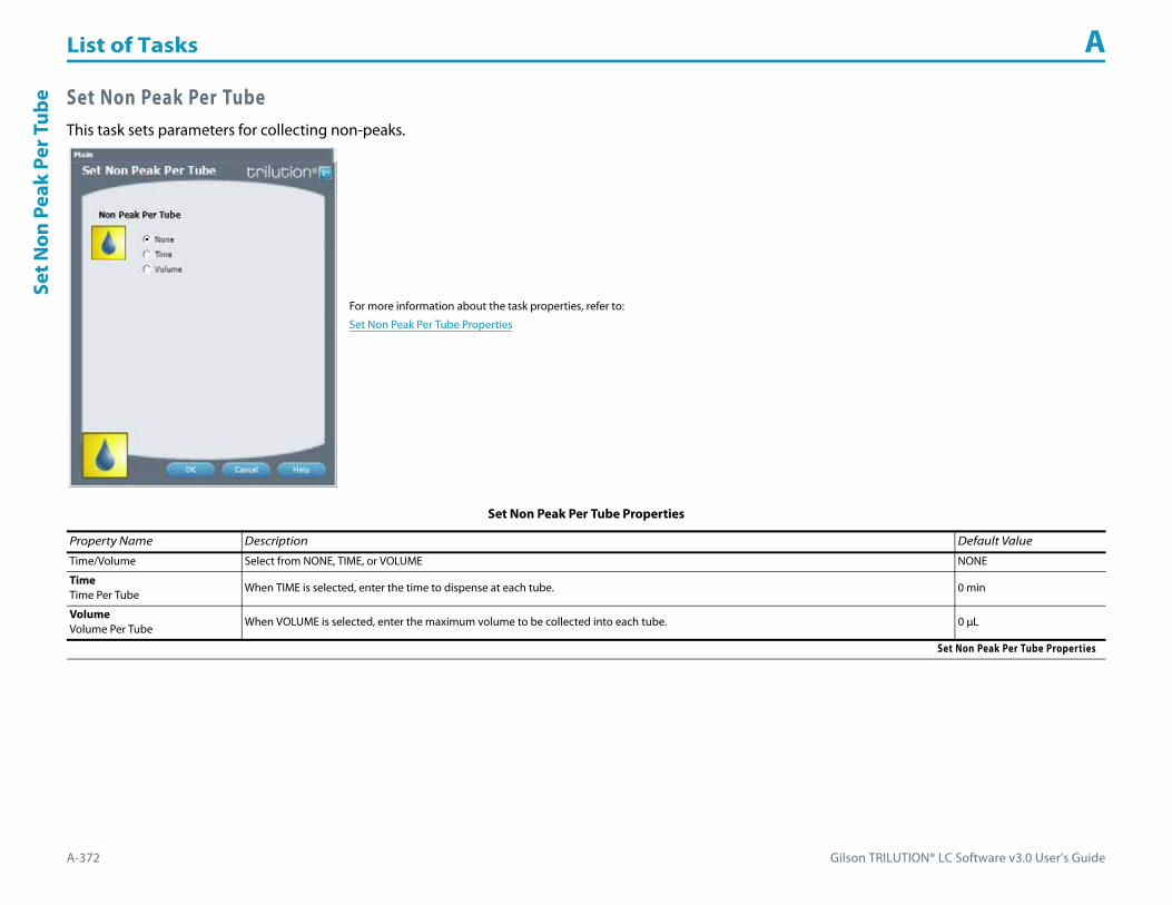
List of Tasks A
A-372 Gilson TRILUTION® LC Software v3.0 User’s Guide
Set N
on P
eak
Per T
ube Set Non Peak Per Tube
This task sets parameters for collecting non-peaks.
For more information about the task properties, refer to:
Set Non Peak Per Tube Properties
Set Non Peak Per Tube Properties
Property Name Description Default Value
Time/Volume Select from NONE, TIME, or VOLUME NONE
TimeTime Per Tube
When TIME is selected, enter the time to dispense at each tube. 0 min
VolumeVolume Per Tube
When VOLUME is selected, enter the maximum volume to be collected into each tube. 0 μL
Set Non Peak Per Tube Properties
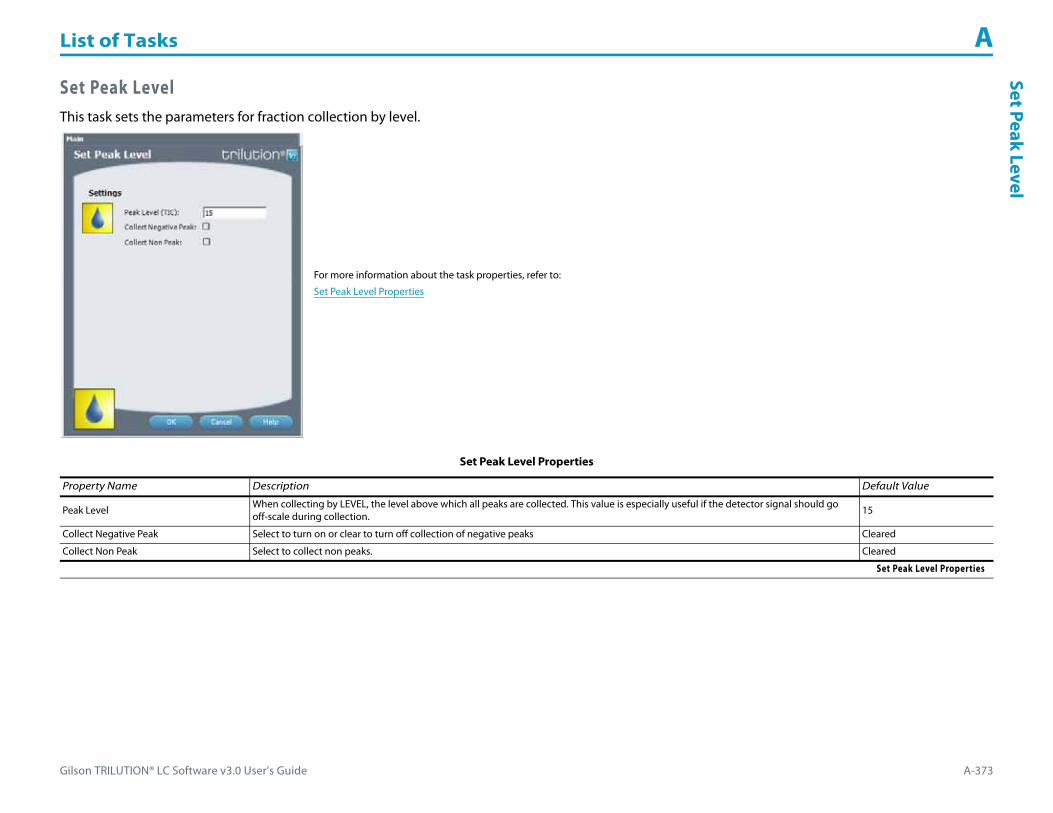
Gilson TRILUTION® LC Software v3.0 User’s Guide A-373
List of Tasks ASet Peak Level
Set Peak LevelThis task sets the parameters for fraction collection by level.
For more information about the task properties, refer to:
Set Peak Level Properties
Set Peak Level Properties
Property Name Description Default Value
Peak Level When collecting by LEVEL, the level above which all peaks are collected. This value is especially useful if the detector signal should go off-scale during collection. 15
Collect Negative Peak Select to turn on or clear to turn off collection of negative peaks Cleared
Collect Non Peak Select to collect non peaks. Cleared
Set Peak Level Properties

List of Tasks A
A-374 Gilson TRILUTION® LC Software v3.0 User’s Guide
Set P
eak
Per T
ube Set Peak Per Tube
This task sets parameters for collecting peaks.
For more information about the task properties, refer to:
Set Peak Per Tube Properties
Set Peak Per Tube Properties
Property Name Description Default Value
Time/Volume Select from None, Time, or Volume. None
TimeTime Per Tube
Enter the time to dispense at each tube. 0 min
VolumeVolume Per Tube
Enter the maximum volume to be collected into each tube. 0 μL
Set Peak Per Tube Properties

Gilson TRILUTION® LC Software v3.0 User’s Guide A-375
List of Tasks ASet Peak Slope
Set Peak SlopeThis task sets the parameters for fraction collection by slope.
For more information about the task properties, refer to:
Set Peak Slope Properties
Set Peak Slope Properties
Property Name Description Default Value
Peak Front SlopeConsider the angle of the peak’s ascending edge when setting the value for Peak Front Slope.
A smaller Peak Front Slope value will collect smaller, sharper peaks. To reduce the number of small peaks collected, increase the Peak Front Slope value.25
Peak Back SlopeConsider the angle of the peak’s descending edge when setting the value for Peak Back Slope.
If the peak has significant tailing, the Peak Back Slope value should be increased to reduce the amount of the tail that is collected or decreased to increase the amount of the tail that is collected.
25
Peak Width The size of the data window that is used to calculate whether the slope condition has been met. If the trace has a lot of noise, set a higher value to reduce the number of smaller peaks that are collected or set a lower value to increase the number of smaller peaks that are collected. 0.2 min
Collection RegionIndicate whether the front of the slope to the apex (Front APEX), the apex to the tail (APEX Tail) or the entire peak (ALL) should be collected. To collect the entire peak, but advance to the next well at the apex, select APEX.
Refer to Appendix D, Fraction Collection Techniques for examples of how the Collection Region option is used.ALL
Collect Negative Peaks Select to turn on or clear to turn off the collection of negative and positive peaks Cleared
Co-eluted Peaks Select to turn on or clear to turn off the collection of co-eluted peaks. Cleared
Collect Non Peak Select to collect non peaks. Cleared
Set Peak Slope Properties

List of Tasks A
A-376 Gilson TRILUTION® LC Software v3.0 User’s Guide
Set P
eak
Wid
th Set Peak WidthThis task sets the Peak Width and Mode on the selected Detector.
For more information about the task properties, refer to:
Set Peak Width Properties
Set Peak Width Properties
Property Name Description Default Value
Detector The detector that the task will affect. Detector
Mode Select from DUAL, SCAN, or SINGLE. DUAL
Peak Width
The detector must know the width of the narrowest peak in the run. The detector uses this information to optimize the presentation of peaks and to minimize baseline noise.
To set the peak width accurately, run a chromatogram using the minimum peak width setting. Measure the width at half height of the narrowest peak.
Valid range is 0 and 4–99 seconds for SINGLE or SCAN mode or 4–99 for DUAL mode.
0 sec
Set Peak Width Properties

Gilson TRILUTION® LC Software v3.0 User’s Guide A-377
List of Tasks ASet Sensitivity
Set Sensitivity This task sets the sensitivities for monitoring a sample on separate output channels on the selected Detector.
For more information about the task properties, refer to:
Set Sensitivity Properties
Set Sensitivity Properties
Property Name Description Default Value
Detector The detector that the task will affect. Detector
Mode Select from Single Mode, Dual Mode, or Scan Mode. Dual Mode
Single ModeSensitivity 1
One of two sensitivities for monitoring a sample on separate output channels. Valid range is 0.001 to 2.0 AUFS. 0.01
Single ModeSensitivity 2
One of two sensitivities for monitoring a sample on separate output channels. Valid range is 0.001 to 2.0 AUFS. 0.01
Dual ModeSensitivity 1
One of two sensitivities for monitoring a sample on separate output channels. Valid range is 0.001 to 2.0 AUFS. 0.01
Dual ModeSensitivity 2
One of two sensitivities for monitoring a sample on separate output channels. Valid range is 0.001 to 2.0 AUFS. 0.01
Scan ModeSensitivity 1
One of two sensitivities for monitoring a sample on separate output channels. Valid range is 0.001 to 2.0 AUFS. 0.01
Set Sensitivity Properties (Page 1 of 2)

List of Tasks A
A-378 Gilson TRILUTION® LC Software v3.0 User’s Guide
Set S
ensi
tivi
ty
Scan ModeSensitivity 2
One of two sensitivities for monitoring a sample on separate output channels. Valid range is 0.001 to 2.0 AUFS. 0.01
Scan ModeScan Sensitivity
The sensitivity for monitoring output channel 3. Valid range is 0.001–2.000 AUFS 0.01
Set Sensitivity Properties (Continued)
Property Name Description Default Value
Set Sensitivity Properties (Page 2 of 2)
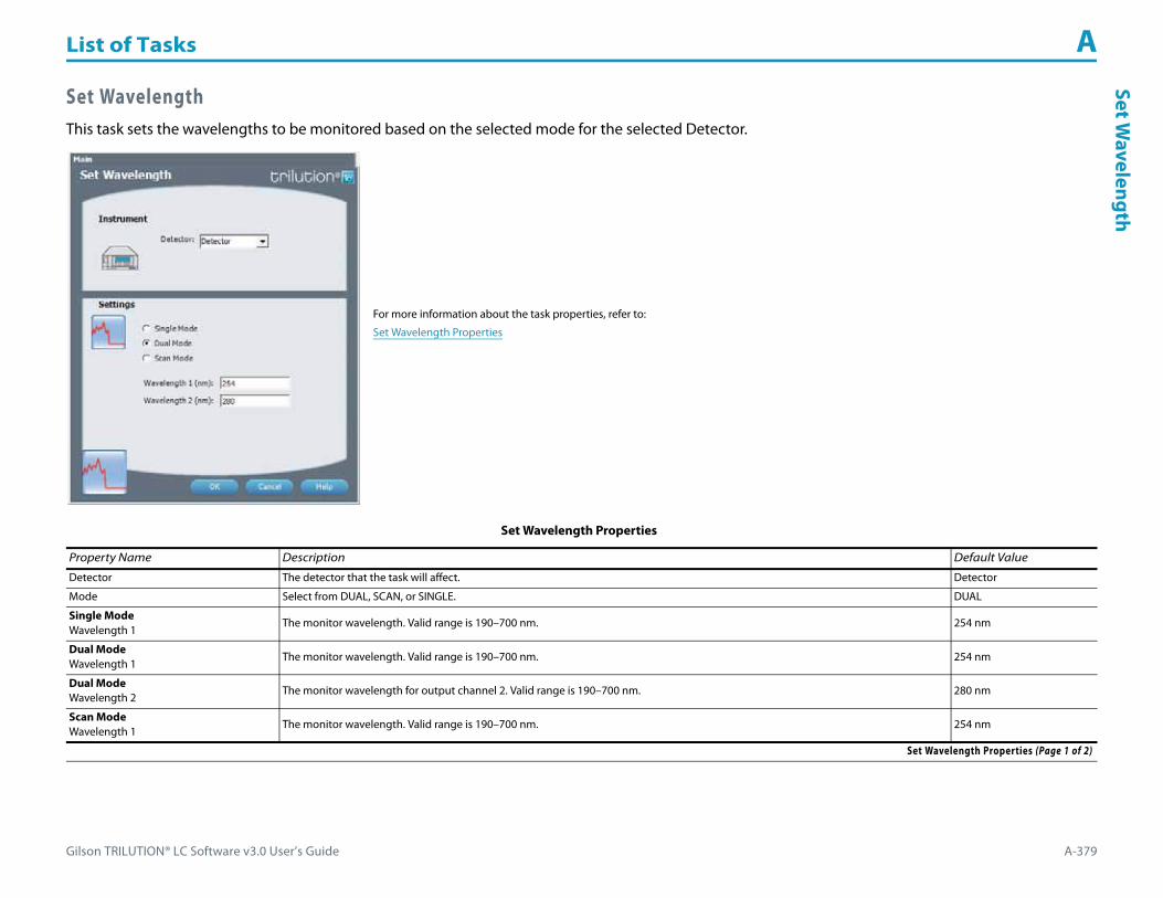
Gilson TRILUTION® LC Software v3.0 User’s Guide A-379
List of Tasks ASet W
avelength
Set WavelengthThis task sets the wavelengths to be monitored based on the selected mode for the selected Detector.
For more information about the task properties, refer to:
Set Wavelength Properties
Set Wavelength Properties
Property Name Description Default Value
Detector The detector that the task will affect. Detector
Mode Select from DUAL, SCAN, or SINGLE. DUAL
Single ModeWavelength 1
The monitor wavelength. Valid range is 190–700 nm. 254 nm
Dual ModeWavelength 1
The monitor wavelength. Valid range is 190–700 nm. 254 nm
Dual ModeWavelength 2
The monitor wavelength for output channel 2. Valid range is 190–700 nm. 280 nm
Scan ModeWavelength 1
The monitor wavelength. Valid range is 190–700 nm. 254 nm
Set Wavelength Properties (Page 1 of 2)

List of Tasks A
A-380 Gilson TRILUTION® LC Software v3.0 User’s Guide
Set W
avel
engt
h
Scan ModeScan Start Wavelength
The first wavelength in the range that will be scanned. Valid range is 190–700 nm. 190 nm
Scan ModeScan End Wavelength
The last wavelength in the range that will be scanned. Valid range is 190–700 nm. 700 nm
Set Wavelength Properties (Continued)
Property Name Description Default Value
Set Wavelength Properties (Page 2 of 2)

Gilson TRILUTION® LC Software v3.0 User’s Guide A-381
List of Tasks ASolvent Valve Position
Solvent Valve PositionThis task switches the solvent valve on the specified pump.
For more information about the task properties, refer to:
Solvent Valve Position Properties
Solvent Valve Position Properties
Property Name Description Default Value
Pump The pump that the task will affect. Pump
Solvent Valve The desired position of the solvent valve on the Pump. Valid range is 1–6. 1
Solvent Valve Position Properties

List of Tasks A
A-382 Gilson TRILUTION® LC Software v3.0 User’s Guide
Star
tDat
a Co
llect
ion Start Data Collection
This task tells TRILUTION LC to begin collecting data. This task has no properties to set.

Gilson TRILUTION® LC Software v3.0 User’s Guide A-383
List of Tasks AStartFraction
Collection
Start Fraction CollectionThis task tells TRILUTION LC to begin collecting fractions. This task has no properties to set.

List of Tasks A
A-384 Gilson TRILUTION® LC Software v3.0 User’s Guide
Star
t Mak
e U
p Pu
mp Start Make Up Pump
This task starts flow from the specified make up pump.
For more information about the task properties, refer to:
Start Make Up Pump Properties
Start Make Up Pump Properties
Property Name Description Default Value
Make Up Pump The make up pump that the task will affect. Make Up Pump
Flow Rate The speed at which liquid flows out of the make up pump. 0 mL/min
Start Make Up Pump Properties
Gilson TRILUTION® LC Software v3.0 User’s Guide A-385
List of Tasks AStop D
ata Collection
Stop Data CollectionThis task tells TRILUTION LC to stop collecting data. This task has no properties to set.

List of Tasks A
A-386 Gilson TRILUTION® LC Software v3.0 User’s Guide
Stop
Mak
e U
p Pu
mp Stop Make Up Pump
This task stops flow from the specified make up pump.
For more information about the task properties, refer to:
Stop Make Up Pump Properties
Stop Make Up Pump Properties
Property Name Description Default Value
Make Up Pump The make up pump that the task will affect. Make Up Pump
Stop Make Up Pump Properties

Gilson TRILUTION® LC Software v3.0 User’s Guide A-387
List of Tasks AStop Fraction
Collection
Stop Fraction CollectionThis task tells TRILUTION LC to stop collecting fractions. This task has no properties to set.

List of Tasks A
A-388 Gilson TRILUTION® LC Software v3.0 User’s Guide
Swit
ch V
ALV
EMAT
E Switch VALVEMATEThis task changes the valve position on a VALVEMATE or VALVEMATE II.
For more information about the task properties, refer to:
Switch VALVEMATE Properties
Switch VALVEMATE Properties
Property Name Description Default Value
VALVEMATE The VALVEMATE or VALVEMATE II that the task will affect. Valve
PositionThe desired position of the valve on the VALVEMATE or VALVEMATE II.
Note: When using a 2-position valve on a VALVEMATE, choose 1 for position 0 or 2 for position 1.1
Switch VALVEMATE Properties

Gilson TRILUTION® LC Software v3.0 User’s Guide A-389
List of Tasks ASync
SyncThis task coordinates steps in a task with a time in a method.
For more information about the properties on each tab, refer to:
Sync Properties
Sync - Sequence of Steps
Sync Properties
Property Name Description Default Value
Time Type the time at which the Method will begin to wait.
Tasks In the Tasks drop-down, select the task to which to synchronize.
Message In the Message drop-down, select the Message to display while waiting for the synchronize.
Sync with Synchronize Type the number that corresponds to the Synchronize in the task. For example, if three Synchronize commands were inserted in the task, typing 1 would synchronize the Method to the first Synchronize command in the task. Typing three would synchronize the Method to the last Synchronize command in the task. 1
Sync to end of task The Method will wait until the task completes.
Pause Run Time Select to pause the run time while waiting.
Sync Properties

List of Tasks A
A-390 Gilson TRILUTION® LC Software v3.0 User’s Guide
Sync Sync - Sequence of Steps
To set a synchronize to coordinate a step in a task with a time in a method:
1 Insert one or more Sync Wait Done commands in the task.Note: Gilson-supplied injection tasks include one Sync Wait Done command.
2 Insert that task in the method.3 Insert a Sync task in the method.
a) In the Time box, type the time at which the method will wait for the Synchronize in the task.b) In the Tasks drop-down, select the task to which to synchronize.c) Optionally, type a message to display while the software waits.d) Select the option button to either Sync with synchronize or Sync to end of Task.
If Sync with synchronize, then also type the number that corresponds to the Synchronize in the task. For example, if three Synchronize commands were inserted in the task, typing 1 would synchronize the method to the first Synchronize command in the task. Typing 3 would synchronize the method to the last Synchronize command in the task.If Sync to end of Task is selected, the method will wait until the task completes.
e) Optionally, select the Pause Run Time check box to pause the run time while the software waits and the pause time advances.
The Sync task displays as a blue vertical line in the control. During the run, the Pause Time displays underneath the Run Time while the software waits.

Gilson TRILUTION® LC Software v3.0 User’s Guide A-391
List of Tasks ATotal Loop Injection O
verfill
Total Loop Injection OverfillThis task performs a total loop injection.
For more information about the properties on each tab, refer to:
Total Loop Injection Overfill Properties - Main
Total Loop Injection Overfill Properties - Advanced
Total Loop Injection Overfill Properties - Rinsing
Total Loop Injection Overfill - Sequence of Steps
Total Loop Injection Overfill Properties - Main
Property Name Description Default Value
Liquid Handler The liquid handler that the task will affect. Liquid Handler
Pump The pump that the task will affect. Pump
Sample Zone The zone from which the Extra Volume and Loop Volume are aspirated. Sample Zone
Sample Well Enter the well number in the Sample Zone. 0
Injection Zone The zone to which the Extra Volume and Loop Volume are dispensed. Injection Zone
Total Loop Injection Overfill Properties - Main (Page 1 of 2)
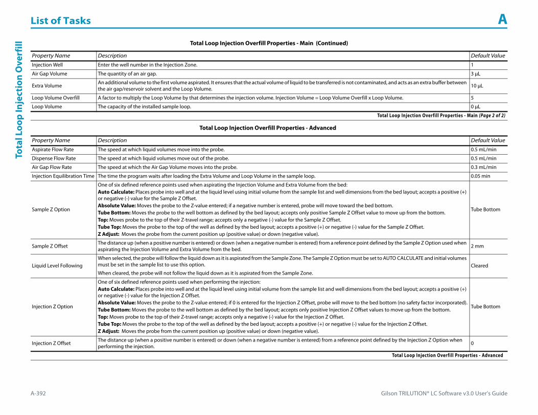
List of Tasks A
A-392 Gilson TRILUTION® LC Software v3.0 User’s Guide
Tota
l Loo
p In
ject
ion
Ove
rfill
Injection Well Enter the well number in the Injection Zone. 1
Air Gap Volume The quantity of an air gap. 3 μL
Extra Volume An additional volume to the first volume aspirated. It ensures that the actual volume of liquid to be transferred is not contaminated, and acts as an extra buffer between the air gap/reservoir solvent and the Loop Volume. 10 μL
Loop Volume Overfill A factor to multiply the Loop Volume by that determines the injection volume. Injection Volume = Loop Volume Overfill x Loop Volume. 5
Loop Volume The capacity of the installed sample loop. 0 μL
Total Loop Injection Overfill Properties - Advanced
Property Name Description Default Value
Aspirate Flow Rate The speed at which liquid volumes move into the probe. 0.5 mL/min
Dispense Flow Rate The speed at which liquid volumes move out of the probe. 0.5 mL/min
Air Gap Flow Rate The speed at which the Air Gap Volume moves into the probe. 0.3 mL/min
Injection Equilibration Time The time the program waits after loading the Extra Volume and Loop Volume in the sample loop. 0.05 min
Sample Z Option
One of six defined reference points used when aspirating the Injection Volume and Extra Volume from the bed:Auto Calculate: Places probe into well and at the liquid level using initial volume from the sample list and well dimensions from the bed layout; accepts a positive (+) or negative (-) value for the Sample Z Offset.Absolute Value: Moves the probe to the Z-value entered; if a negative number is entered, probe will move toward the bed bottom.Tube Bottom: Moves the probe to the well bottom as defined by the bed layout; accepts only positive Sample Z Offset value to move up from the bottom.Top: Moves probe to the top of their Z-travel range; accepts only a negative (-) value for the Sample Z Offset.Tube Top: Moves the probe to the top of the well as defined by the bed layout; accepts a positive (+) or negative (-) value for the Sample Z Offset.Z Adjust: Moves the probe from the current position up (positive value) or down (negative value).
Tube Bottom
Sample Z Offset The distance up (when a positive number is entered) or down (when a negative number is entered) from a reference point defined by the Sample Z Option used when aspirating the Injection Volume and Extra Volume from the bed. 2 mm
Liquid Level FollowingWhen selected, the probe will follow the liquid down as it is aspirated from the Sample Zone. The Sample Z Option must be set to AUTO CALCULATE and initial volumes must be set in the sample list to use this option.
When cleared, the probe will not follow the liquid down as it is aspirated from the Sample Zone.Cleared
Injection Z Option
One of six defined reference points used when performing the injection:Auto Calculate: Places probe into well and at the liquid level using initial volume from the sample list and well dimensions from the bed layout; accepts a positive (+) or negative (-) value for the Injection Z Offset.Absolute Value: Moves the probe to the Z-value entered; if 0 is entered for the Injection Z Offset, probe will move to the bed bottom (no safety factor incorporated).Tube Bottom: Moves the probe to the well bottom as defined by the bed layout; accepts only positive Injection Z Offset values to move up from the bottom.Top: Moves probe to the top of their Z-travel range; accepts only a negative (-) value for the Injection Z Offset.Tube Top: Moves the probe to the top of the well as defined by the bed layout; accepts a positive (+) or negative (-) value for the Injection Z Offset.Z Adjust: Moves the probe from the current position up (positive value) or down (negative value).
Tube Bottom
Injection Z Offset The distance up (when a positive number is entered) or down (when a negative number is entered) from a reference point defined by the Injection Z Option when performing the injection. 0
Total Loop Injection Overfill Properties - Advanced
Total Loop Injection Overfill Properties - Main (Continued)
Property Name Description Default Value
Total Loop Injection Overfill Properties - Main (Page 2 of 2)

Gilson TRILUTION® LC Software v3.0 User’s Guide A-393
List of Tasks ATotal Loop Injection O
verfill
Total Loop Injection Overfill Properties - Rinsing
Property Name Description Default Value
Drain Zone The zone in which the dilutor is homed. Inside Rinse
Drain Well Enter the well number in the Drain Zone. 1
Drain Z Option
One of six defined reference points used when purging to the drain:Auto Calculate: Places probe into well and at the liquid level using initial volume from the sample list and well dimensions from the bed layout; accepts a positive (+) or negative (-) value for the Drain Z Offset.Absolute Value: Moves the probe to the Z-value entered; if 0 is entered for the Drain Z Offset, probe will move to the bed bottom (no safety factor incorporated).Tube Bottom: Moves the probe to the well bottom as defined by the bed layout; accepts only positive Drain Z Offset values to move up from the bottom.Top: Moves probe to the top of their Z-travel range; accepts only a negative (-) value for the Drain Z Offset.Tube Top: Moves the probe to the top of the well as defined by the bed layout; accepts a positive (+) or negative (-) value for the Drain Z Offset.Z Adjust: Moves the probe from the current position up (positive value) or down (negative value).
Tube Top
Drain Z Offset The distance up (when a positive number is entered) or down (when a negative number is entered) from a reference point defined by the Drain Z Option for purging to the drain. -7
Injection Rinse Volume The quantity of liquid used to rinse the injection port at Injection Well in Injection Zone. 500 μL
Injection Rinse Flow Rate The speed at which the Injection Rinse Volume moves out of the probe and into the injection port. 4 mL/min
Outside Rinse Zone The zone to which the Outside Rinse Volume is delivered. Outside Rinse
Outside Rinse Well Enter the well number in the Outside Rinse Zone. 1
Outside Rinse Volume The quantity of liquid used to rinse the outside of the probe. 500 μL
Outside Rinse Flow Rate The speed at which the Outside Rinse Volume moves out of the probe and into the outside rinse position in the rinse station. 10 mL/min
Outside Rinse Z Option
One of six defined reference points used when performing the outside rinse:Auto Calculate: Places probe into well and at the liquid level using initial volume from the sample list and well dimensions from the bed layout; accepts a positive (+) or negative (-) value for the Outside Rinse Z Offset.Absolute Value: Moves the probe to the Z-value entered; if a negative number is entered, probe will move toward the bed bottom.Tube Bottom: Moves the probe to the well bottom as defined by the bed layout; accepts only positive Outside Rinse Z Offset values to move up from the bottom.Top: Moves probe to the top of their Z-travel range; accepts only a negative (-) value for the Outside Rinse Z Offset.Tube Top: Moves the probe to the top of the well as defined by the bed layout; accepts a positive (+) or negative (-) value for the Outside Rinse Z Offset.Z Adjust: Moves the probe from the current position up (positive value) or down (negative value).
Tube Bottom
Outside Rinse Z Offset The distance up (when a positive number is entered) or down (when a negative number is entered) from a reference point defined by the Outside Rinse Z Option for rinsing the probe at the outside rinse position in the rinse station. 2 mm
Total Loop Injection Overfill Properties - Rinsing

List of Tasks A
A-394 Gilson TRILUTION® LC Software v3.0 User’s Guide
Tota
l Loo
p In
ject
ion
Ove
rfill Total Loop Injection Overfill - Sequence of Steps
The following is an overview for the sequence of steps.
1 Initialize2 Aspirate3 Inject4 Injection Port Rinse5 Outside Rinse
Initialize1 Move Z to Z Safe Height.2 Set injection valve to INJECT.3 Move to Drain Well in Drain Zone.4 Lower probe into well to Drain Z Option and Drain Z Offset.5 Home dilutor.6 Move Z to Z Safe Height.
Aspirate1 Aspirate Air Gap Volume at Air Gap Flow Rate.2 Move to Sample Well in Sample Zone.3 Lower probe into well to Sample Z Option and Sample Z Offset.4 Aspirate the injection volume (injection volume = Loop Overfill x Loop Volume) + Extra Volume at Aspirate Flow Rate.5 Move Z to Z Safe Height.
Inject1 Move to Injection Well in Injection Zone.2 Lower probe into well to Injection Z Option and Injection Z Offset.3 Switch injection valve to LOAD.4 Wait 1.2 sec.5 Dispense the injection volume (injection volume = Loop Overfill x Loop Volume) at Dispense Flow Rate.6 Wait Injection Equilibration Time.7 Synchronize.

Gilson TRILUTION® LC Software v3.0 User’s Guide A-395
List of Tasks ATotal Loop Injection O
verfill
Injection Port Rinse1 Switch injection valve to INJECT.2 Home dilutor.3 Aspirate Injection Rinse Volume or syringe capacity (from Reservoir) at Injection Rinse Flow Rate.4 Dispense Injection Rinse Volume or syringe capacity at Injection Rinse Flow Rate.5 Repeat steps 3–4 until requested rinse volume is aspirated and dispensed.6 Move Z to Z Safe Height.
Outside Rinse1 Move to Outside Rinse Well in Outside Rinse Zone.2 Lower probe into well to Outside Rinse Z Option and Outside Rinse Z Offset.3 Home dilutor.4 Aspirate Outside Rinse Volume or syringe capacity (from Reservoir) at Outside Rinse Flow Rate.5 Dispense Outside Rinse Volume or syringe capacity at Outside Rinse Flow Rate.6 Repeat steps 4–5 until requested rinse volume is aspirated and dispensed.

List of Tasks A
A-396 Gilson TRILUTION® LC Software v3.0 User’s Guide
Tran
sfer Transfer
This task aspirates the specified volume of liquid (Source Volume) from the probe and then dispenses the volume to the wells of the result zone.
For more information about the properties on each tab, refer to:
Transfer Properties - Main
Transfer Properties - Advanced
Transfer Properties - Rinsing
Transfer - Sequence of Steps
Transfer Properties - Main
Property Name Description Default Value
Liquid Handler The liquid handler that the task will affect. Liquid Handler
Pump The pump that the task will affect. Pump
Source Zone The zone from which the Source Volume and Extra Volume are drawn. Sample Zone
Source Well Enter the well number in the Source Zone. 0
Result Zone The zone to which the Source Volume is delivered. Sample Zone
Result Well Enter the well number in the Result Zone. 0
Number of Wells to Transfer The number of Source Wells to transfer to Result Wells. 1
Transfer Properties - Main (Page 1 of 2)

Gilson TRILUTION® LC Software v3.0 User’s Guide A-397
List of Tasks ATransferAir Gap Volume The quantity of the air gap aspirated before the Source Volume. 6 μL
Source Volume The quantity of sample 0 μL
Extra Volume An additional volume to the first volume aspirated. It ensures that the actual volume of liquid to be transferred is not contaminated, and acts as an extra buffer between the air gap/reservoir solvent and the Source Volume. 0 μL
Transfer Properties - Advanced
Property Name Description Default Value
Aspirate Flow Rate The speed at which the Source Volume and Extra Volume move into the probe. 1.5 mL/min
Dispense Flow Rate The speed at which the Source Volume moves out of the probe. 3 mL/min
Air Gap Flow Rate The speed at which the Air Gap Volume moves into the probe. 0.3 mL/min
Aspirate Z Option
One of six defined reference points used when drawing liquids from the bed:Auto Calculate: Places probe into well and at the liquid level using initial volume from the sample list and well dimensions from the bed layout; accepts a positive (+) or negative (-) value for the Aspirate Z Offset.Absolute Value: Moves the probe to the Z-value entered; if 0 is entered for the Aspirate Z Offset, the probe will move to the bed bottom (no safety factor incorporated).Tube Bottom: Moves the probe to the well bottom as defined by the bed layout; accepts only positive Aspirate Z Offset value to move up from the bottom.Top: Moves probe to the top of their Z-travel range; accepts only a negative (-) value for the Aspirate Z Offset.Tube Top: Moves the probe to the top of the well as defined by the bed layout; accepts a positive (+) or negative (-) value for the Aspirate Z Offset.Z Adjust: Moves the probe from the current position up (positive value) or down (negative value).
Tube Bottom
Aspirate Z Offset The distance up (when a positive number is entered) or down (when a negative number is entered) from a reference point defined by the Aspirate Z Option for drawing liquids from the bed. 2 mm
Aspirate LLFWhen selected the probe will follow the liquid down as it is aspirated from the Source Zone. The Aspirate Z Option must be set to AUTO CALCULATE and initial volumes must be set in the sample list to use this option.
When cleared, the probe will not follow the liquid down as it is aspirated from the Source Zone.Cleared
Dispense Z Option
One of six defined reference points used when delivering liquids to the bed:Auto Calculate: Places probe into well and at the liquid level using initial volume from the sample list and well dimensions from the bed layout; accepts a positive (+) or negative (-) value for the Dispense Z Offset.Absolute Value: Moves the probe to the Z-value entered; if 0 is entered for the Dispense Z Offset, the probe will move to the bed bottom (no safety factor incorporated).Tube Bottom: Moves the probe to the well bottom as defined by the bed layout; accepts only positive Dispense Z Offset value to move up from the bottom.Top: Moves probe to the top of their Z-travel range; accepts only a negative (-) value for the Dispense Z Offset.Tube Top: Moves the probe to the top of the well as defined by the bed layout; accepts a positive (+) or negative (-) value for the Dispense Z Offset. Z Adjust: Moves the probe from the current position up (positive value) or down (negative value).
Tube Bottom
Dispense Z Offset The distance up (when a positive number is entered) or down (when a negative number is entered) from a reference point defined by the Dispense Z Option for delivering liquids to the bed. 2 mm
Dispense LLFWhen selected the probe will follow the liquid up as it is delivered to the Result Zone. The Dispense Z Option must be set to AUTO CALCULATE and initial volumes must be set in the sample list to use this option.
When cleared, the probe will not follow the liquid up as it is delivered to the Result Zone.Cleared
Transfer Properties - Advanced
Transfer Properties - Main (Continued)
Property Name Description Default Value
Transfer Properties - Main (Page 2 of 2)

List of Tasks A
A-398 Gilson TRILUTION® LC Software v3.0 User’s Guide
Tran
sfer Transfer Properties - Rinsing
For information about rinse positions, refer to Appendix B, Rinse Locations.
Property Name Description Default Value
Inside Rinse Zone The zone to which the Inside Rinse Volume is delivered. Inside Rinse
Inside Rinse Well Enter the well number in the Inside Rinse Zone. 1
Inside Rinse Volume The quantity of liquid used to rinse the inside of the probe. 250 μL
Inside Rinse Flow Rate The speed at which the Inside Rinse Volume moves out of the probe and into the inside rinse position in the rinse station. 10 mL/min
Inside Rinse Z Option
One of six defined reference points used when performing the inside rinse:Auto Calculate: Places probe into well and at the liquid level using initial volume from the sample list and well dimensions from the bed layout; accepts a positive (+) or negative (-) value for the Inside Rinse Z Offset.Absolute Value: Moves the probe to the Z-value entered; if 0 is entered for the Inside Rinse Z Offset, the probe will move to the bed bottom (no safety factor incorporated).Tube Bottom: Moves the probe to the well bottom as defined by the bed layout; accepts only positive Inside Rinse Z Offset values to move up from the bottom.Top: Moves probe to the top of their Z-travel range; accepts only a negative (-) value for the Inside Rinse Z Offset.Tube Top: Moves the probe to the top of the well as defined by the bed layout; accepts a positive (+) or negative (-) value for the Inside Rinse Z Offset.Z Adjust: Moves the probe from the current position up (positive value) or down (negative value).
Tube Bottom
Inside Rinse Z Offset The distance up (when a positive number is entered) or down (when a negative number is entered) from a reference point defined by the Inside Rinse Z Option for rinsing the probe at the inside rinse position in the rinse station. 2 mm
Outside Rinse Zone The zone to which the Outside Rinse Volume is delivered. Outside Rinse
Outside Rinse Well Enter the well number in the Outside Rinse Zone. 1
Outside Rinse Volume The quantity of liquid used to rinse the outside of the probe. 500 μL
Outside Rinse Flow Rate The speed at which the Outside Rinse Volume moves out of the probe and into the outside rinse position in the rinse station. 10 mL/min
Outside Rinse Z Option
One of six defined reference points used when performing the outside rinse:Auto Calculate: Places probe into well and at the liquid level using initial volume from the sample list and well dimensions from the bed layout; accepts a positive (+) or negative (-) value for the Outside Rinse Z Offset.Absolute Value: Moves the probe to the Z-value entered; if 0 is entered for the Outside Rinse Z Offset, the probe will move to the bed bottom (no safety factor incorporated).Tube Bottom: Moves the probe to the well bottom as defined by the bed layout; accepts only positive Outside Rinse Z Offset values to move up from the bottom.Top: Moves probe to the top of their Z-travel range; accepts only a negative (-) value for the Outside Rinse Z Offset.Tube Top: Moves the probe to the top of the well as defined by the bed layout; accepts a positive (+) or negative (-) value for the Outside Rinse Z Offset.Z Adjust: Moves the probe from the current position up (positive value) or down (negative value).
Tube Bottom
Outside Rinse Z Offset The distance up (when a positive number is entered) or down (when a negative number is entered) from a reference point defined by the Outside Rinse Z Option for rinsing the probe at the outside rinse position in the rinse station. 2 mm
Transfer Properties - Rinsing

Gilson TRILUTION® LC Software v3.0 User’s Guide A-399
List of Tasks ATransfer
Transfer - Sequence of StepsThe following is an overview for the sequence of steps.
1 Aspirate2 Dispense3 Inside Rinse4 Outside Rinse
Aspirate1 Move Z to Z Safe Height.2 Aspirate Air Gap Volume at Air Gap Flow Rate.3 Move to Source Well in Source Zone.4 Lower probe to Aspirate Z Option and Aspirate Z Offset.5 Aspirate Source Volume + Extra Volume at Aspirate Flow Rate.6 Move Z to Z Safe Height.
Dispense1 Move to Result Well in Result Zone.2 Lower probe to Dispense Z Option and Dispense Z Offset.3 Dispense Source Volume at Dispense Flow Rate.4 Move Z to Z Safe Height.
Inside Rinse1 Move to Inside Rinse Well in Inside Rinse Zone.2 Lower probe into well to Inside Rinse Z Option and Inside Rinse Z Offset.3 Home dilutor.4 Aspirate Inside Rinse Volume or syringe capacity (from Reservoir) at Inside Rinse Flow Rate.5 Dispense Inside Rinse Volume or syringe capacity (from Reservoir) at Inside Rinse Flow Rate.6 Repeat steps 4–5 until requested rinse volume is aspirated and dispensed.7 Move Z to Z Safe Height.
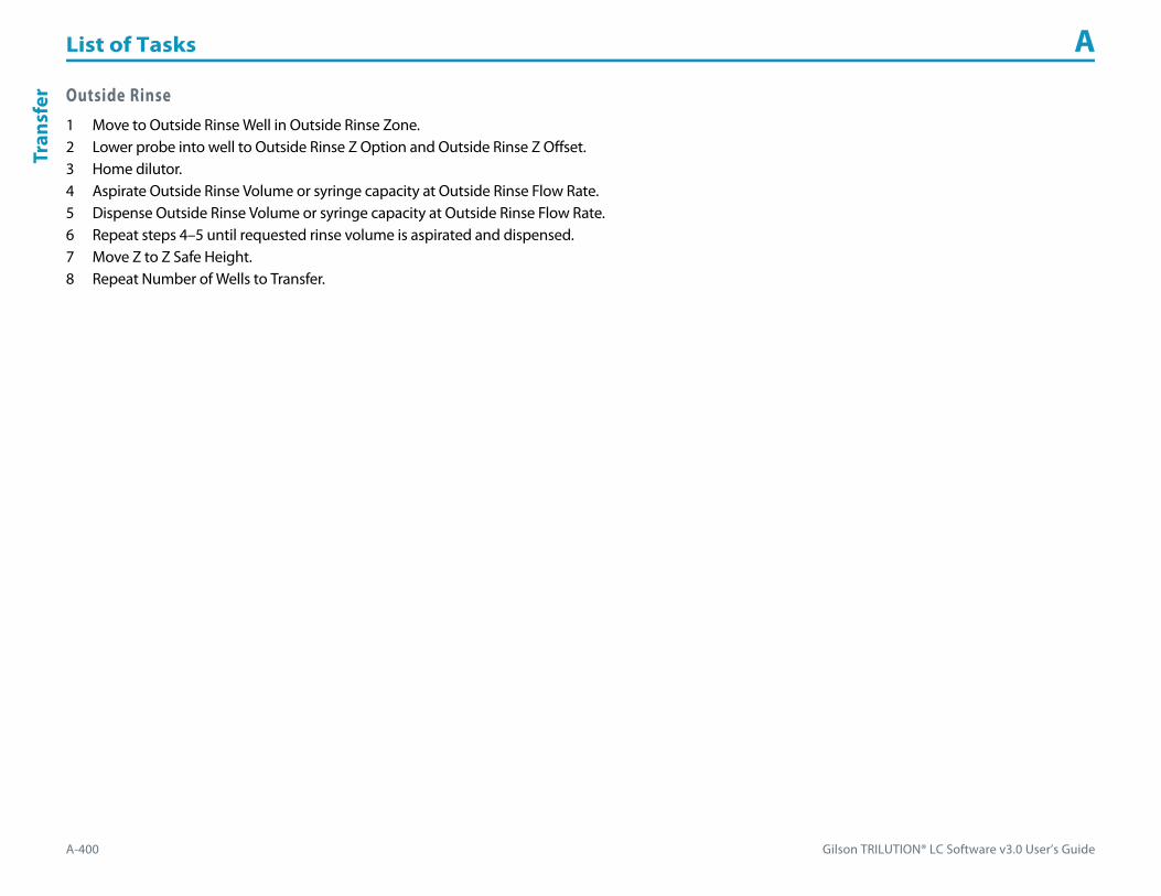
List of Tasks A
A-400 Gilson TRILUTION® LC Software v3.0 User’s Guide
Tran
sfer Outside Rinse
1 Move to Outside Rinse Well in Outside Rinse Zone.2 Lower probe into well to Outside Rinse Z Option and Outside Rinse Z Offset.3 Home dilutor.4 Aspirate Outside Rinse Volume or syringe capacity at Outside Rinse Flow Rate.5 Dispense Outside Rinse Volume or syringe capacity at Outside Rinse Flow Rate.6 Repeat steps 4–5 until requested rinse volume is aspirated and dispensed.7 Move Z to Z Safe Height.8 Repeat Number of Wells to Transfer.
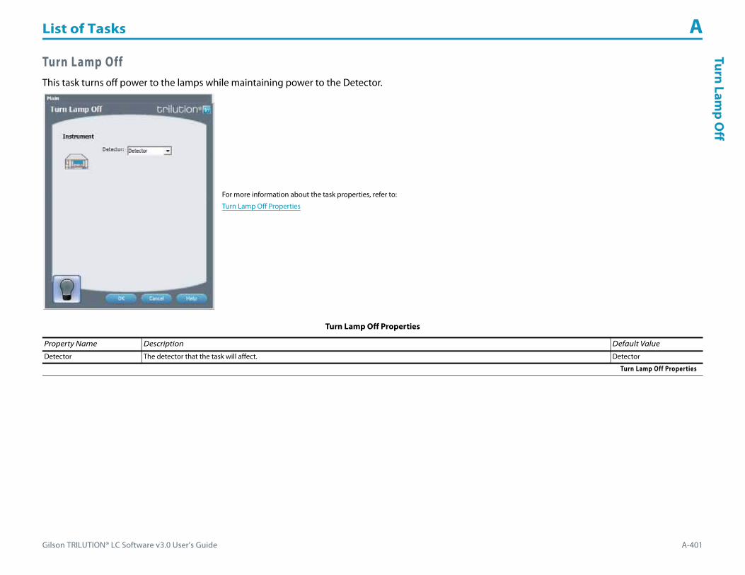
Gilson TRILUTION® LC Software v3.0 User’s Guide A-401
List of Tasks ATurn Lam
p Off
Turn Lamp OffThis task turns off power to the lamps while maintaining power to the Detector.
For more information about the task properties, refer to:
Turn Lamp Off Properties
Turn Lamp Off Properties
Property Name Description Default Value
Detector The detector that the task will affect. Detector
Turn Lamp Off Properties

List of Tasks A
A-402 Gilson TRILUTION® LC Software v3.0 User’s Guide
Turn
Lam
p O
n Turn Lamp OnThis task turns the UV and visible lamps on for the specified Detector.
For more information about the task properties, refer to:
Turn Lamp On Properties
Turn Lamp On Properties
Property Name Description Default Value
Detector The detector that the task will affect. Detector
Turn Lamp On Properties

Gilson TRILUTION® LC Software v3.0 User’s Guide A-403
List of Tasks AVoltage O
n - Off
Voltage On - OffThis task opens and powers off or closes and powers on a specified contact on a specified liquid handler.
For more information about the task properties, refer to:
Voltage On - Off Properties
Voltage On - Off Properties
Property Name Description Default Value
Liquid Handler The liquid handler that the task will affect. Liquid Handler
Contact ID Enter the number that corresponds to the output contact to act on for the liquid handler selected. 1
Voltage ON OFF The action to occur: open and power off (OFF) or close and power on (ON) the Contact ID. OFF
Voltage On - Off Properties

List of Tasks A
A-404 Gilson TRILUTION® LC Software v3.0 User’s Guide
Wai
t for
Con
tact Wait for Contact
This task initiates a wait in the method until any contact state change or a user-specified contact state change for the specified contact is detected. Sync to the end of the task (using a Sync task) to prevent other tasks in the method from executing during the wait.
For more information about the task properties, refer to:
Wait for Contact Properties
Wait for Contact Properties
Property Name Description Default Value
Instrument The instrument that the task will affect. Liquid Handler
Contact ID The input contact being monitored for a state change. A
Message Enter the text to display in the message box.
Wait for Contact State Change Select to initiate a wait in the method until any contact state change of the specified contact (Contact ID) is detected. Sync to the end of the task (using a Sync task) to prevent other tasks in the method from executing during the wait. Selected
Wait for Specific Contact StateClosed (On)
Select to initiate a wait in the method until the specified contact (Contact ID) closes. Sync to the end of the task (using a Sync task) to prevent other tasks in the method from executing during the wait.
Wait for Specific Contact StateOpen (Off )
Select to initiate a wait in the method until the specified contact (Contact ID) opens. Sync to the end of the task (using a Sync task) to prevent other tasks in the method from executing during the wait.
Wait for Contact Properties
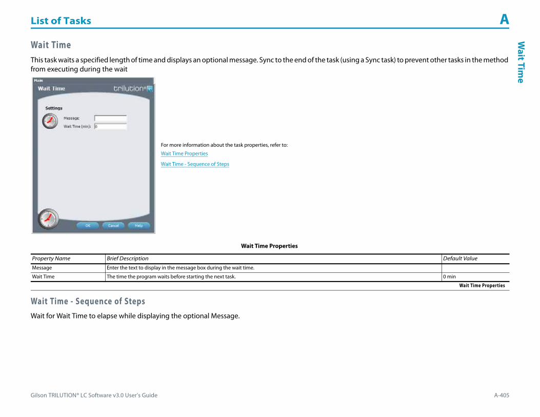
Gilson TRILUTION® LC Software v3.0 User’s Guide A-405
List of Tasks AW
ait Time
Wait TimeThis task waits a specified length of time and displays an optional message. Sync to the end of the task (using a Sync task) to prevent other tasks in the method from executing during the wait
Wait Time - Sequence of StepsWait for Wait Time to elapse while displaying the optional Message.
For more information about the task properties, refer to:
Wait Time Properties
Wait Time - Sequence of Steps
Wait Time Properties
Property Name Brief Description Default Value
Message Enter the text to display in the message box during the wait time.
Wait Time The time the program waits before starting the next task. 0 min
Wait Time Properties

List of Tasks A
A-406 Gilson TRILUTION® LC Software v3.0 User’s Guide
Wri
te to
Dis
play Write to Display
This task displays a message in the front panel display of the selected instrument.
For more information about the task properties, refer to:
Write to Display Properties
Write to Display Properties
Property Name Description Default Value
Instrument The instrument that the task will affect. Liquid Handler
Message Enter the text to display on the front panel of the instrument. Message
Line For two-line displays, indicate the line on which to display the message. 1
Write to Display Properties

Gilson TRILUTION® LC Software v3.0 User’s Guide A-407
List of Tasks AXL Low
Volume Partial Loop Injection
XL Low Volume Partial Loop InjectionThis task performs a partial loop injection using a push volume from the reservoir to push the injection volume into the sample loop.
For more information about the properties on each tab, refer to:
XL Low Volume Partial Loop Injection Properties - Main
XL Low Volume Partial Loop Injection Properties - Advanced
XL Low Volume Partial Loop Injection Properties - Rinsing
XL Low Volume Partial Loop Injection - Sequence of Steps
XL Low Volume Partial Loop Injection Properties - Main
Property Name Description Default Value
Sample Injector The sample injector that the task will affect. Liquid Handler
Pump The pump that the task will affect. Pump
Sample Zone The zone from which the Injection Volume and Extra Volume are aspirated. Sample Zone
Sample Well Enter the well number in the Sample Zone. 0
Injection Zone The zone to which the Extra Volume, Injection Volume, and Push Volume are dispensed. Injection Zone
XL Low Volume Partial Loop Injection Properties - Main (Page 1 of 2)

List of Tasks A
A-408 Gilson TRILUTION® LC Software v3.0 User’s Guide
XL L
ow V
olum
e Pa
rtia
l Loo
p In
ject
ion
Injection Well Enter the well number in the Injection Zone. 1
Air Gap Volume The quantity of an air gap. 3 μL
Extra Volume An additional volume to the first volume aspirated. It ensures that the actual volume of liquid to be transferred is not contaminated, and acts as an extra buffer between the air gap/reservoir solvent and the Injection Volume. 10 μL
Push Volume A volume of reservoir solvent used to push the injection volume into the sample loop. 10 μL
Injection Volume The volume of sample to be injected. 0 μL
XL Low Volume Partial Loop Injection Properties - Advanced
Property Name Description Default Value
Aspirate Flow Rate The speed at which liquid volumes move into the probe. 0.5 mL/min
Dispense Flow Rate The speed at which liquid volumes move out of the probe. 0.5 mL/min
Air Gap Flow Rate The speed at which the Air Gap Volume moves into the probe. 0.3 mL/min
Injection Equilibration Time The time the program waits after loading the Extra Volume, Injection Volume, and Push Volume in the sample loop. 0.05 min
Sample Z Option
One of six defined reference points used when aspirating the Injection Volume and Extra Volume from the bed:Auto Calculate: Places probe into well and at the liquid level using initial volume from the sample list and well dimensions from the bed layout; accepts a positive (+) or negative (-) value for the Sample Z Offset.Absolute Value: Moves the probe to the Z-value entered; if a negative number is entered, probe will move toward the bed bottom.Tube Bottom: Moves the probe to the well bottom as defined by the bed layout; accepts only positive Sample Z Offset value to move up from the bottom.Top: Moves probe to the top of their Z-travel range; accepts only a negative (-) value for the Sample Z Offset.Tube Top: Moves the probe to the top of the well as defined by the bed layout; accepts a positive (+) or negative (-) value for the Sample Z Offset.Z Adjust: Moves the probe from the current position up (positive value) or down (negative value).
Tube Bottom
Sample Z Offset The distance up (when a positive number is entered) or down (when a negative number is entered) from a reference point defined by the Sample Z Option used when aspirating the Injection Volume and Extra Volume from the bed. 2 mm
Liquid Level FollowingWhen selected, the probe will follow the liquid down as it is aspirated from the Sample Zone. The Sample Z Option must be set to AUTO CALCULATE and initial volumes must be set in the sample list to use this option.
When cleared, the probe will not follow the liquid down as it is aspirated from the Sample Zone.Cleared
Injection Z Option
One of six defined reference points used when injecting the Injection Volume and Push Volume:Auto Calculate: Places probe into well and at the liquid level using initial volume from the sample list and well dimensions from the bed layout; accepts a positive (+) or negative (-) value for the Injection Z Offset.Absolute Value: Moves the probe to the Z-value entered; if a negative number is entered, probe will move toward the bed bottom.Tube Bottom: Moves the probe to the well bottom as defined by the bed layout; accepts only positive Injection Z Offset value to move up from the bottom.Top: Moves probe to the top of their Z-travel range; accepts only a negative (-) value for the Injection Z Offset.Tube Top: Moves the probe to the top of the well as defined by the bed layout; accepts a positive (+) or negative (-) value for the Injection Z Offset.Z Adjust: Moves the probe from the current position up (positive value) or down (negative value).
Tube Bottom
Injection Z Offset The distance up (when a positive number is entered) or down (when a negative number is entered) from a reference point defined by the Injection Z Option used when injecting the Injection Volume and Push Volume. 2.2 mm
XL Low Volume Partial Loop Injection Properties - Advanced
XL Low Volume Partial Loop Injection Properties - Main (Continued)
Property Name Description Default Value
XL Low Volume Partial Loop Injection Properties - Main (Page 2 of 2)

Gilson TRILUTION® LC Software v3.0 User’s Guide A-409
List of Tasks AXL Low
Volume Partial Loop Injection
XL Low Volume Partial Loop Injection - Sequence of StepsThe following is an overview for the sequence of steps.
1 Initialize2 Aspirate3 Inject4 Injection Port Rinse5 Outside Rinse
XL Low Volume Partial Loop Injection Properties - Rinsing
Property Name Description Default Value
Drain Zone The zone in which the dilutor is homed. Inside Rinse
Drain Well Enter the well number in the Drain Zone. 1
Drain Z Option
One of six defined reference points used when purging to the drain:Auto Calculate: Places probe into well and at the liquid level using initial volume from the sample list and well dimensions from the bed layout; accepts a positive (+) or negative (-) value for the Drain Z Offset.Absolute Value: Moves the probe to the Z-value entered; if 0 is entered for the Drain Z Offset, probe will move to the bed bottom (no safety factor incorporated).Tube Bottom: Moves the probe to the well bottom as defined by the bed layout; accepts only positive Drain Z Offset values to move up from the bottom.Top: Moves probe to the top of their Z-travel range; accepts only a negative (-) value for the Drain Z Offset.Tube Top: Moves the probe to the top of the well as defined by the bed layout; accepts a positive (+) or negative (-) value for the Drain Z Offset.Z Adjust: Moves the probe from the current position up (positive value) or down (negative value).
Tube Bottom
Drain Z Offset The distance up (when a positive number is entered) or down (when a negative number is entered) from a reference point defined by the Drain Z Option for purging to the drain. 2
Injection Rinse Volume The quantity of liquid used to rinse the injection port at Injection Well in Injection Zone. 250 μL
Injection Rinse Flow Rate The speed at which the Injection Rinse Volume moves out of the probe and into the injection port. 4 mL/min
Outside Rinse Zone The zone to which the Outside Rinse Volume is delivered. Outside Rinse
Outside Rinse Well Enter the well number in the Outside Rinse Zone. 1
Outside Rinse Volume The quantity of liquid used to rinse the outside of the probe. 450 μL
Outside Rinse Flow Rate The speed at which the Outside Rinse Volume moves out of the probe and into the outside rinse position in the rinse station. 10 mL/min
Outside Rinse Z Option
One of six defined reference points used when performing the outside rinse:Auto Calculate: Places probe into well and at the liquid level using initial volume from the sample list and well dimensions from the bed layout; accepts a positive (+) or negative (-) value for the Outside Rinse Z Offset.Absolute Value: Moves the probe to the Z-value entered; if a negative number is entered, probe will move toward the bed bottom.Tube Bottom: Moves the probe to the well bottom as defined by the bed layout; accepts only positive Outside Rinse Z Offset values to move up from the bottom.Top: Moves probe to the top of their Z-travel range; accepts only a negative (-) value for the Outside Rinse Z Offset.Tube Top: Moves the probe to the top of the well as defined by the bed layout; accepts a positive (+) or negative (-) value for the Outside Rinse Z Offset.Z Adjust: Moves the probe from the current position up (positive value) or down (negative value).
Tube Bottom
Outside Rinse Z Offset The distance up (when a positive number is entered) or down (when a negative number is entered) from a reference point defined by the Outside Rinse Z Option for rinsing the probe at the outside rinse position in the rinse station. 2 mm
XL Low Volume Partial Loop Injection Properties - Rinsing

List of Tasks A
A-410 Gilson TRILUTION® LC Software v3.0 User’s Guide
XL L
ow V
olum
e Pa
rtia
l Loo
p In
ject
ion Initialize
1 Move Z to Z Safe Height.2 Set injection valve to INJECT.3 Move to Drain Well in Drain Zone. 4 Lower probe into well to Drain Z Option and Drain Z Offset.5 Home dilutor.6 Move Z to Z Safe Height.
Aspirate1 Switch Dilutor Valve to Probe and aspirate Air Gap Volume at Air Gap Flow Rate.2 Switch Dilutor Valve to Reservoir and aspirate Push Volume at Aspirate Flow Rate.3 Move to Sample Well in Sample Zone.4 Lower probe into well to Sample Z Option and Sample Z Offset.5 Switch Dilutor Valve to Probe and aspirate Injection Volume + Extra Volume at Aspirate Flow Rate.6 Move Z to Z Safe Height.
Inject1 Move to Injection Well in Injection Zone.2 Lower probe into well to Injection Z Option and Injection Z Offset3 Dispense Extra Volume at Dispense Flow Rate.4 Switch injection valve to LOAD.5 Wait 1.2 sec.6 Dispense Injection Volume + Push Volume at Dispense Flow Rate.7 Wait Injection Equilibration Time.8 Synchronize.9 Switch injection valve to INJECT.
Injection Port Rinse1 Home dilutor.2 Switch dilutor valve to Reservoir and aspirate Injection Rinse Volume or syringe capacity at Injection Rinse Flow Rate.3 Switch dilutor valve to probe and dispense Injection Rinse Volume or syringe capacity at Injection Rinse Flow Rate.4 Repeat steps 2–3 until requested rinse volume is aspirated and dispensed.5 Move Z to Z Safe Height.

Gilson TRILUTION® LC Software v3.0 User’s Guide A-411
List of Tasks AXL Low
Volume Partial Loop Injection
Outside Rinse1 Move to Outside Rinse Well in Outside Rinse Zone.2 Lower probe into well to Outside Rinse Z Option and Outside Rinse Z Offset.3 Home dilutor.4 Switch dilutor valve to reservoir aspirate Outside Rinse Volume or syringe capacity at Outside Rinse Flow Rate.5 Switch dilutor valve to probe dispense Outside Rinse Volume or syringe capacity at Outside Rinse Flow Rate.6 Repeat steps 4–5 until requested rinse volume is aspirated and dispensed.7 Move Z to Z Safe Height.

List of Tasks A
A-412 Gilson TRILUTION® LC Software v3.0 User’s Guide
XL P
arti
al L
oop
Inje
ctio
n XL Partial Loop InjectionThis task performs a partial loop injection.
For more information about the properties on each tab, refer to:
XL Partial Loop Injection Properties - Main
XL Partial Loop Injection Properties - Advanced
XL Partial Loop Injection Properties - Rinsing
XL Partial Loop Injection - Sequence of Steps
XL Partial Loop Injection Properties - Main
Property Name Description Default Value
Sample Injector The sample injector that the task will affect. Liquid Handler
Pump The pump that the task will affect. Pump
Sample Zone The zone from which the Injection Volume and Extra Volume are aspirated. Sample Zone
Sample Well Enter the well number in the Sample Zone. 0
Injection Zone The zone to which the Extra Volume, Injection Volume, and Push Volume are dispensed. Injection Zone
Injection Well Enter the well number in the Injection Zone. 1
Air Gap Volume The quantity of an air gap. 3 μL
Extra Volume An additional volume to the first volume aspirated. It ensures that the actual volume of liquid to be transferred is not contaminated, and acts as an extra buffer between the air gap/reservoir solvent and the Injection Volume. 10 μL
Injection Volume The volume of sample to be injected. 0 μL
XL Partial Loop Injection Properties - Main

Gilson TRILUTION® LC Software v3.0 User’s Guide A-413
List of Tasks AXL Partial Loop Injection
XL Partial Loop Injection Properties - Advanced
Property Name Description Default Value
Aspirate Flow Rate The speed at which liquid volumes move into the probe. 0.5 mL/min
Dispense Flow Rate The speed at which liquid volumes move out of the probe. 0.5 mL/min
Air Gap Flow Rate The speed at which the Air Gap Volume moves into the probe. 0.3 mL/min
Injection Equilibration Time The time the program waits after loading the Extra Volume, Injection Volume, and Push Volume in the sample loop. 0.05 min
Sample Z Option
One of six defined reference points used when aspirating the Injection Volume and Extra Volume from the bed:Auto Calculate: Places probe into well and at the liquid level using initial volume from the sample list and well dimensions from the bed layout; accepts a positive (+) or negative (-) value for the Sample Z Offset.Absolute Value: Moves the probe to the Z-value entered; if a negative number is entered, probe will move toward the bed bottom.Tube Bottom: Moves the probe to the well bottom as defined by the bed layout; accepts only positive Sample Z Offset value to move up from the bottom.Top: Moves probe to the top of their Z-travel range; accepts only a negative (-) value for the Sample Z Offset.Tube Top: Moves the probe to the top of the well as defined by the bed layout; accepts a positive (+) or negative (-) value for the Sample Z Offset.Z Adjust: Moves the probe from the current position up (positive value) or down (negative value).
Tube Bottom
Sample Z Offset The distance up (when a positive number is entered) or down (when a negative number is entered) from a reference point defined by the Sample Z Option used when aspirating the Injection Volume and Extra Volume from the bed. 2 mm
Liquid Level FollowingWhen selected, the probe will follow the liquid down as it is aspirated from the Sample Zone. The Sample Z Option must be set to AUTO CALCULATE and initial volumes must be set in the sample list to use this option.
When cleared, the probe will not follow the liquid down as it is aspirated from the Sample Zone.Cleared
Injection Z Option
One of six defined reference points used when injecting the Injection Volume and Push Volume:Auto Calculate: Places probe into well and at the liquid level using initial volume from the sample list and well dimensions from the bed layout; accepts a positive (+) or negative (-) value for the Injection Z Offset.Absolute Value: Moves the probe to the Z-value entered; if a negative number is entered, probe will move toward the bed bottom.Tube Bottom: Moves the probe to the well bottom as defined by the bed layout; accepts only positive Injection Z Offset value to move up from the bottom.Top: Moves probe to the top of their Z-travel range; accepts only a negative (-) value for the Injection Z Offset.Tube Top: Moves the probe to the top of the well as defined by the bed layout; accepts a positive (+) or negative (-) value for the Injection Z Offset.Z Adjust: Moves the probe from the current position up (positive value) or down (negative value).
Tube Bottom
Injection Z Offset The distance up (when a positive number is entered) or down (when a negative number is entered) from a reference point defined by the Injection Z Option used when injecting the Injection Volume and Push Volume. 2.2 mm
XL Partial Loop Injection Properties - Advanced
XL Partial Loop Injection Properties - Rinsing
Property Name Description Default Value
Drain Zone The zone in which the dilutor is homed. Inside Rinse
Drain Well Enter the well number in the Drain Zone. 1
XL Partial Loop Injection Properties - Rinsing (Page 1 of 2)

List of Tasks A
A-414 Gilson TRILUTION® LC Software v3.0 User’s Guide
XL P
arti
al L
oop
Inje
ctio
n
XL Partial Loop Injection - Sequence of StepsThe following is an overview for the sequence of steps.
1 Initialize2 Aspirate3 Inject4 Injection Port Rinse5 Outside Rinse
Drain Z Option
One of six defined reference points used when purging to the drain:Auto Calculate: Places probe into well and at the liquid level using initial volume from the sample list and well dimensions from the bed layout; accepts a positive (+) or negative (-) value for the Drain Z Offset.Absolute Value: Moves the probe to the Z-value entered; if 0 is entered for the Drain Z Offset, probe will move to the bed bottom (no safety factor incorporated).Tube Bottom: Moves the probe to the well bottom as defined by the bed layout; accepts only positive Drain Z Offset values to move up from the bottom.Top: Moves probe to the top of their Z-travel range; accepts only a negative (-) value for the Drain Z Offset.Tube Top: Moves the probe to the top of the well as defined by the bed layout; accepts a positive (+) or negative (-) value for the Drain Z Offset.Z Adjust: Moves the probe from the current position up (positive value) or down (negative value).
Tube Bottom
Drain Z Offset The distance up (when a positive number is entered) or down (when a negative number is entered) from a reference point defined by the Drain Z Option for purging to the drain.
2
Injection Rinse Volume The quantity of liquid used to rinse the injection port at Injection Well in Injection Zone. 250 μL
Injection Rinse Flow Rate The speed at which the Injection Rinse Volume moves out of the probe and into the injection port. 4 mL/min
Outside Rinse Zone The zone to which the Outside Rinse Volume is delivered. Outside Rinse
Outside Rinse Well Enter the well number in the Outside Rinse Zone. 1
Outside Rinse Volume The quantity of liquid used to rinse the outside of the probe. 450 μL
Outside Rinse Flow Rate The speed at which the Outside Rinse Volume moves out of the probe and into the outside rinse position in the rinse station. 10 mL/min
Outside Rinse Z Option
One of five defined reference points used when performing the outside rinse:Auto Calculate: Places probe into well and at the liquid level using initial volume from the sample list and well dimensions from the bed layout; accepts a positive (+) or negative (-) value for the Outside Rinse Z Offset.Absolute Value: Moves the probe to the Z-value entered; if a negative number is entered, probe will move toward the bed bottom.Tube Bottom: Moves the probe to the well bottom as defined by the bed layout; accepts only positive Outside Rinse Z Offset values to move up from the bottom.Top: Moves probe to the top of their Z-travel range; accepts only a negative (-) value for the Outside Rinse Z Offset.Tube Top: Moves the probe to the top of the well as defined by the bed layout; accepts a positive (+) or negative (-) value for the Outside Rinse Z Offset.
Tube Bottom
Outside Rinse Z Offset The distance up (when a positive number is entered) or down (when a negative number is entered) from a reference point defined by the Outside Rinse Z Option for rinsing the probe at the outside rinse position in the rinse station. 2 mm
XL Partial Loop Injection Properties - Rinsing (Continued)
Property Name Description Default Value
XL Partial Loop Injection Properties - Rinsing (Page 2 of 2)

Gilson TRILUTION® LC Software v3.0 User’s Guide A-415
List of Tasks AXL Partial Loop Injection
Initialize1 Move Z to Z Safe Height.2 Set injection valve to INJECT.3 Move to Drain Well in Drain Zone.4 Lower probe into well to Drain Z Option and Drain Z Offset.5 Home dilutor.6 Move Z to Z Safe Height.
Aspirate1 Switch dilutor valve to probe and aspirate Air Gap Volume at Air Gap Flow Rate.2 Move to Sample Well in Sample Zone.3 Lower probe into well to Sample Z Option and Sample Z Offset.4 Aspirate Injection Volume + Extra Volume at Aspirate Flow Rate.5 Move Z to Z Safe Height.
Inject1 Move to Injection Well in Injection Zone.2 Lower probe into well to Injection Z Option and Injection Z Offset3 Dispense Extra Volume at Dispense Flow Rate.4 Switch injection valve to LOAD.5 Wait 1.2 sec.6 Dispense Injection Volume at Dispense Flow Rate.7 Wait Injection Equilibration Time.8 Synchronize.9 Switch Injection valve to INJECT.
Injection Port Rinse1 Home dilutor.2 Switch dilutor valve to Reservoir and aspirate Injection Rinse Volume or syringe capacity at Injection Rinse Flow Rate.3 Switch dilutor valve to probe and dispense Injection Rinse Volume or syringe capacity at Injection Rinse Flow Rate.4 Repeat steps 2–3 until requested rinse volume is aspirated and dispensed.5 Move Z to Z Safe Height.
List of Tasks A
A-416 Gilson TRILUTION® LC Software v3.0 User’s Guide
XL P
arti
al L
oop
Inje
ctio
n Outside Rinse1 Move to Outside Rinse Well in Outside Rinse Zone.2 Lower probe into well to Outside Rinse Z Option and Outside Rinse Z Offset.3 Home dilutor.4 Switch dilutor valve to reservoir aspirate Outside Rinse Volume or syringe capacity at Outside Rinse Flow Rate.5 Switch dilutor valve to probe dispense Outside Rinse Volume or syringe capacity at Outside Rinse Flow Rate.6 Repeat steps 4–5 until requested rinse volume is aspirated and dispensed.7 Move Z to Z Safe Height.

Gilson TRILUTION® LC Software v3.0 User’s Guide A-417
List of Tasks AXL Total Loop Injection
XL Total Loop InjectionThis task performs a total loop injection.
For more information about the properties on each tab, refer to:
XL Total Loop Injection Properties - Main
XL Total Loop Injection Properties - Advanced
XL Total Loop Injection Properties - Rinsing
XL Total Loop Injection - Sequence of Steps
XL Total Loop Injection Properties - Main
Property Name Description Default Value
Sample Injector The sample injector that the task will affect. Liquid Handler
Pump The pump that the task will affect. Liquid Handler
Sample Zone The zone from which the Injection Volume and Extra Volume are aspirated. Sample Zone
Sample Well Enter the well number in the Sample Zone. 0
Injection Zone The zone to which the Extra Volume, Injection Volume, and Push Volume are dispensed. Injection Zone
XL Total Loop Injection Properties - Main (Page 1 of 2)

List of Tasks A
A-418 Gilson TRILUTION® LC Software v3.0 User’s Guide
XL T
otal
Loo
p In
ject
ion
Injection Well Enter the well number in the Injection Zone. 1
Air Gap Volume The quantity of an air gap. 3 μL
Extra Volume An additional volume to the first volume aspirated. It ensures that the actual volume of liquid to be transferred is not contaminated, and acts as an extra buffer between the air gap/reservoir solvent and the Injection Volume. 10 μL
Loop Volume Overfill A factor to multiply the Loop Volume by that determines the injection volume. Injection Volume = Loop Volume Overfill x Loop Volume. 5
Loop Volume The capacity of the installed sample loop. 0 μL
XL Total Loop Injection Properties - Advanced
Property Name Description Default Value
Aspirate Flow Rate The speed at which liquid volumes move into the probe. 0.5 mL/min
Dispense Flow Rate The speed at which liquid volumes move out of the probe. 0.5 mL/min
Air Gap Flow Rate The speed at which the Air Gap Volume moves into the probe. 0.3 mL/min
Injection Equilibration Time The time the program waits after loading the Extra Volume, Injection Volume, and Push Volume in the sample loop. 0.05 min
Sample Z Option
One of six defined reference points used when aspirating the Injection Volume and Extra Volume from the bed:Auto Calculate: Places probe into well and at the liquid level using initial volume from the sample list and well dimensions from the bed layout; accepts a positive (+) or negative (-) value for the Sample Z Offset.Absolute Value: Moves the probe to the Z-value entered; if a negative number is entered, probe will move toward the bed bottom.Tube Bottom: Moves the probe to the well bottom as defined by the bed layout; accepts only positive Sample Z Offset value to move up from the bottom.Top: Moves probe to the top of their Z-travel range; accepts only a negative (-) value for the Sample Z Offset.Tube Top: Moves the probe to the top of the well as defined by the bed layout; accepts a positive (+) or negative (-) value for the Sample Z Offset.Z Adjust: Moves the probe from the current position up (positive value) or down (negative value).
Tube Bottom
Sample Z Offset The distance up (when a positive number is entered) or down (when a negative number is entered) from a reference point defined by the Sample Z Option used when aspirating the Injection Volume and Extra Volume from the bed. 2 mm
Liquid Level FollowingWhen selected, the probe will follow the liquid down as it is aspirated from the Sample Zone. The Sample Z Option must be set to AUTO CALCULATE and initial volumes must be set in the sample list to use this option.
When cleared, the probe will not follow the liquid down as it is aspirated from the Sample Zone.Cleared
Injection Z Option
One of six defined reference points used when injecting the Injection Volume and Push Volume:Auto Calculate: Places probe into well and at the liquid level using initial volume from the sample list and well dimensions from the bed layout; accepts a positive (+) or negative (-) value for the Injection Z Offset.Absolute Value: Moves the probe to the Z-value entered; if a negative number is entered, probe will move toward the bed bottom.Tube Bottom: Moves the probe to the well bottom as defined by the bed layout; accepts only positive Injection Z Offset value to move up from the bottom.Top: Moves probe to the top of their Z-travel range; accepts only a negative (-) value for the Injection Z Offset.Tube Top: Moves the probe to the top of the well as defined by the bed layout; accepts a positive (+) or negative (-) value for the Injection Z Offset.Z Adjust: Moves the probe from the current position up (positive value) or down (negative value).
Tube Bottom
Injection Z Offset The distance up (when a positive number is entered) or down (when a negative number is entered) from a reference point defined by the Injection Z Option used when injecting the Injection Volume and Push Volume. 2.2 mm
XL Total Loop Injection Properties - Advanced
XL Total Loop Injection Properties - Main (Continued)
Property Name Description Default Value
XL Total Loop Injection Properties - Main (Page 2 of 2)

Gilson TRILUTION® LC Software v3.0 User’s Guide A-419
List of Tasks AXL Total Loop Injection
XL Total Loop Injection - Sequence of StepsThe following is an overview for the sequence of steps.
1 Initialize2 Aspirate3 Inject4 Injection Port Rinse5 Outside Rinse
XL Total Loop Injection Properties - Rinsing
Property Name Description Default Value
Drain Zone The zone in which the dilutor is homed. Inside Rinse
Drain Well Enter the well number in the Drain Zone. 1
Drain Z Option
One of five defined reference points used when purging to the drain:Auto Calculate: Places probe into well and at the liquid level using initial volume from the sample list and well dimensions from the bed layout; accepts a positive (+) or negative (-) value for the Drain Z Offset.Absolute Value: Moves the probe to the Z-value entered; if 0 is entered for the Drain Z Offset, probe will move to the bed bottom (no safety factor incorporated).Tube Bottom: Moves the probe to the well bottom as defined by the bed layout; accepts only positive Drain Z Offset values to move up from the bottom.Top: Moves probe to the top of their Z-travel range; accepts only a negative (-) value for the Drain Z Offset.Tube Top: Moves the probe to the top of the well as defined by the bed layout; accepts a positive (+) or negative (-) value for the Drain Z Offset.
Tube Bottom
Drain Z Offset The distance up (when a positive number is entered) or down (when a negative number is entered) from a reference point defined by the Drain Z Option for purging to the drain. 2
Injection Rinse Volume The quantity of liquid used to rinse the injection port at Injection Well in Injection Zone. 250 μL
Injection Rinse Flow Rate The speed at which the Injection Rinse Volume moves out of the probe and into the injection port. 4 mL/min
Outside Rinse Zone The zone to which the Outside Rinse Volume is delivered. Outside Rinse
Outside Rinse Well Enter the well number in the Outside Rinse Zone. 1
Outside Rinse Volume The quantity of liquid used to rinse the outside of the probe. 450 μL
Outside Rinse Flow Rate The speed at which the Outside Rinse Volume moves out of the probe and into the outside rinse position in the rinse station. 10 mL/min
Outside Rinse Z Option
One of five defined reference points used when performing the outside rinse:Auto Calculate: Places probe into well and at the liquid level using initial volume from the sample list and well dimensions from the bed layout; accepts a positive (+) or negative (-) value for the Outside Rinse Z Offset.Absolute Value: Moves the probe to the Z-value entered; if a negative number is entered, probe will move toward the bed bottom.Tube Bottom: Moves the probe to the well bottom as defined by the bed layout; accepts only positive Outside Rinse Z Offset values to move up from the bottom.Top: Moves probe to the top of their Z-travel range; accepts only a negative (-) value for the Outside Rinse Z Offset.Tube Top: Moves the probe to the top of the well as defined by the bed layout; accepts a positive (+) or negative (-) value for the Outside Rinse Z Offset.
Tube Bottom
Outside Rinse Z Offset The distance up (when a positive number is entered) or down (when a negative number is entered) from a reference point defined by the Outside Rinse Z Option for rinsing the probe at the outside rinse position in the rinse station. 2 mm
XL Total Loop Injection Properties - Rinsing

List of Tasks A
A-420 Gilson TRILUTION® LC Software v3.0 User’s Guide
XL T
otal
Loo
p In
ject
ion Initialize
1 Move Z to Z Safe Height.2 Set injection valve to INJECT.3 Move to Drain Well in Drain Zone.4 Lower probe into well to Drain Z Option and Drain Z Offset.5 Home dilutor.6 Move Z to Z Safe Height.
Aspirate1 Switch Dilutor Valve to Probe and aspirate Air Gap Volume at Air Gap Flow Rate.2 Move to Sample Well in Sample Zone.3 Lower probe into well to Sample Z Option and Sample Z Offset.4 Aspirate the injection volume (injection volume = Loop Overfill x Loop Volume) + Extra Volume at Aspirate Flow Rate.5 Move Z to Z Safe Height.
Inject1 Move to Injection Well in Injection Zone.2 Lower probe into well to Injection Z Option and Injection Z Offset3 Switch injection valve to LOAD.4 Wait 1.2 sec.5 Dispense the injection volume (injection volume = Loop Overfill x Loop Volume) at Dispense Flow Rate.6 Wait Injection Equilibration Time.7 Synchronize.8 Switch Injection valve to INJECT.
Injection Port Rinse1 Home dilutor.2 Switch dilutor valve to Reservoir and aspirate Injection Rinse Volume or syringe capacity at Injection Rinse Flow Rate.3 Switch dilutor valve to probe and dispense Injection Rinse Volume or syringe capacity at Injection Rinse Flow Rate.4 Repeat steps 2–3 until requested rinse volume is aspirated and dispensed.5 Move Z to Z Safe Height.
Gilson TRILUTION® LC Software v3.0 User’s Guide A-421
List of Tasks AXL Total Loop Injection
Outside Rinse1 Move to Outside Rinse Well in Outside Rinse Zone.2 Lower probe into well to Outside Rinse Z Option and Outside Rinse Z Offset.3 Home dilutor.4 Switch dilutor valve to reservoir aspirate Outside Rinse Volume or syringe capacity at Outside Rinse Flow Rate.5 Switch dilutor valve to probe dispense Outside Rinse Volume or syringe capacity at Outside Rinse Flow Rate.6 Repeat steps 4–5 until requested rinse volume is aspirated and dispensed.7 Move Z to Z Safe Height.
Gilson TRILUTION® LC Software v3.0 User’s Guide B-1
Rinse Locations B
Rinse locations are assigned to zones in the bed layout. Inside and outside rinse zones are then chosen in the task.
This chapter describes the recommended rinse positions for the:• 215 Liquid Handler • GX-271 Liquid Handler• GX-281 Liquid Handler

Rinse Locations B
B-2 Gilson TRILUTION® LC Software v3.0 User’s Guide
Rins
e Lo
cati
ons 215 Liquid Handler
Bed Layout Trays (Templates)215 6-Position for AutoMix215 for Code 517 Rack215 for Five Code 200-Series Racks215 for Seven XL Racks
Rinse 215 (Footprint)
Rinse 215
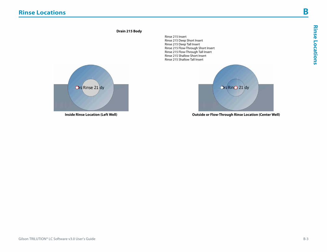
Gilson TRILUTION® LC Software v3.0 User’s Guide B-3
Rinse Locations BRinse Locations
Drain 215 BodyRinse 215 InsertRinse 215 Deep Short InsertRinse 215 Deep Tall InsertRinse 215 Flow-Through Short InsertRinse 215 Flow-Through Tall InsertRinse 215 Shallow Short InsertRinse 215 Shallow Tall Insert
Inside Rinse Location (Left Well) Outside or Flow-Through Rinse Location (Center Well)

Rinse Locations B
B-4 Gilson TRILUTION® LC Software v3.0 User’s Guide
Rins
e Lo
cati
ons GX-271 Liquid Handler
Bed Layout Tray (Template)GX-271 20- and 12X-Series Racks with Direct InjectGX-271 20-Series RacksGX-271 20-Series Racks with Direct InjectGX-271 200-Series RacksGX-271 200-Series Racks with Direct Inject
GX Rinse Stations (Footprint)
GX Rinse Stations

Gilson TRILUTION® LC Software v3.0 User’s Guide B-5
Rinse Locations BRinse Locations
Drain/Rinse Station for Inside Rinse of Probe
Drain/Rinse Station GX Short (Rack)
Use Z Clamp Height (mm) Rinse Station Part Number
Inside Rinse 125 26034554
Drain/Rinse Station GX Short (56 mm Probe) (Rack)
Use Z Clamp Height (mm) Rinse Station Part Number
Inside Rinse 125 26034554
Drain/Rinse Station GX Tall (Rack)
Use Z Clamp Height (mm) Rinse Station Part Number
Inside Rinse 175 26034555
Drain/Rinse Station GX Extra Tall (Rack)
Use Z Clamp Height (mm) Rinse Station Part Number
Inside Rinse 210 26034556

Rinse Locations B
B-6 Gilson TRILUTION® LC Software v3.0 User’s Guide
Rins
e Lo
cati
ons
Rinse Station for Outside Rinse of Probe (Static)
Rinse Station for Outside Rinse of Probe (Flowing)
Rinse Station GX Short (Rack)
Use Z Clamp Height (mm) Rinse Station Part Number
Outside Rinse (static or flowing) 125 26034552
Rinse Station GX Short (56 mm Probe) (Rack)
Use Z Clamp Height (mm) Rinse Station Part Number
Outside Rinse (static or flowing) 125 26034552
Rinse Station GX Tall (Rack)
Use Z Clamp Height (mm) Rinse Station Part Number
Outside Rinse (static or flowing) 175 26034551
Rinse Station GX Extra Tall (Rack)
Use Z Clamp Height (mm) Rinse Station Part Number
Outside Rinse (static or flowing) 210 26034553

Gilson TRILUTION® LC Software v3.0 User’s Guide B-7
Rinse Locations BRinse Locations
GX-281 Liquid Handler
Bed Layout Tray (Template)GX-281
GX Rinse Stations (Footprints)
GX Rinse Stations

Rinse Locations B
B-8 Gilson TRILUTION® LC Software v3.0 User’s Guide
Rins
e Lo
cati
ons
Drain/Rinse Station for Inside Rinse of Probe
Drain/Rinse Station GX Extra Tall (Rack)
Use Z Clamp Height (mm) Rinse Station Part Number
Inside Rinse 210 26034556
Drain/Rinse Station GX Tall (Rack)
Use Z Clamp Height (mm) Rinse Station Part Number
Inside Rinse 175 26034555
Drain/Rinse Station GX Short (Rack)
Use Z Clamp Height (mm) Rinse Station Part Number
Inside Rinse 125 26034554
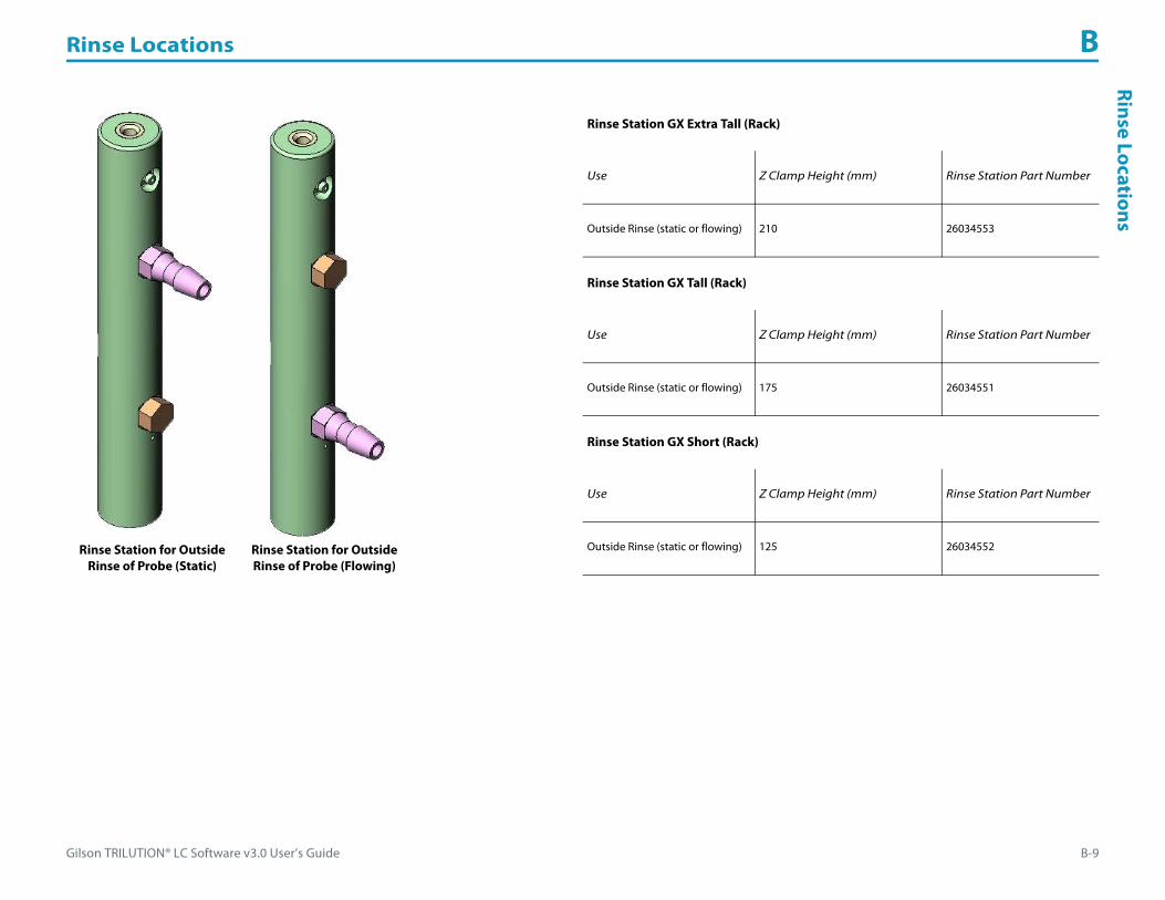
Gilson TRILUTION® LC Software v3.0 User’s Guide B-9
Rinse Locations BRinse Locations
Rinse Station for Outside Rinse of Probe (Static)
Rinse Station for Outside Rinse of Probe (Flowing)
Rinse Station GX Extra Tall (Rack)
Use Z Clamp Height (mm) Rinse Station Part Number
Outside Rinse (static or flowing) 210 26034553
Rinse Station GX Tall (Rack)
Use Z Clamp Height (mm) Rinse Station Part Number
Outside Rinse (static or flowing) 175 26034551
Rinse Station GX Short (Rack)
Use Z Clamp Height (mm) Rinse Station Part Number
Outside Rinse (static or flowing) 125 26034552

Gilson TRILUTION® LC Software v3.0 User’s Guide C-1
Peak Integration C
When integrating, changing the Front and Back Slopes and/or the Peak Width values influence the area of the peak that is integrated and/or how many peaks
are integrated. Changing the Peak Filter affects how many peaks are integrated.
The following examples are provided:
• Effect of Slope on Area
• Effect of Slope on Number of Peaks
• Effect of Peak Width on Number of Peaks
• Effect of Peak Filter on Number of Peaks
• Effect of Baseline Selection

Peak Integration C
C-2 Gilson TRILUTION® LC Software v3.0 User’s Guide
Peak
Inte
grat
ion Effect of Slope on Area
Change Front and Back SlopeThe Front Slope and Back Slope values were the same and were incrementally increased to show how changing the values affects the area of the peak that is integrated. Peak Width was held constant at the default of 0.20 min and the Peak Filter was 0.

Gilson TRILUTION® LC Software v3.0 User’s Guide C-3
Peak Integration CPeak Integration
Change Back Slope OnlyIf the peak has significant tailing, then the Back Slope value should be increased to reduce the area of the tail that is integrated or decreased to increase the area of the tail that is integrated.
The Front Slope value was held constant at the default of 25, Peak Width was 0.20 min, and Peak Filter was 0. Though the Front Slope value was held constant, the start of integration on the front of the peak was shifted to prevent the baseline from crossing the chromatogram trace.

Peak Integration C
C-4 Gilson TRILUTION® LC Software v3.0 User’s Guide
Peak
Inte
grat
ion Effect of Slope on Number of Peaks
If the trace has a lot of noise, set higher slope values to reduce the number of smaller peaks that are integrated or set lower slope values to increase the number of smaller peaks that are integrated. The Peak Width value was held constant at 0.20 min and Peak Filter was 0.
Gilson TRILUTION® LC Software v3.0 User’s Guide C-5
Peak Integration CPeak Integration
Effect of Peak Width on Number of PeaksThe Peak Width setting is the size of the data window that is used to calculate whether the slope condition has been met. The default is 0.20 min. If the trace has a lot of noise, set a higher value to reduce the number of smaller peaks that are integrated or set a lower value to increase the number of smaller peaks that are integrated. The Front and Back Slope values were held constant at 25 and Peak Filter was 0.

Peak Integration C
C-6 Gilson TRILUTION® LC Software v3.0 User’s Guide
Peak
Inte
grat
ion Effect of Peak Filter on Number of Peaks
Peak Filter was left at the default value of 0 (off, no filtering) and then it was set at 0.06 min to show how a peak will not be integrated if the peak width at half height is less than or equal to the Peak Filter setting. The Front Slope, Back Slope and Peak Width values were held constant at the default values (25, 25, and 0.20).
Peak Filter = 0 min
Peak Filter = 0.06 min

Gilson TRILUTION® LC Software v3.0 User’s Guide C-7
Peak Integration CPeak Integration
Effect of Baseline SelectionTRILUTION LC provides several baseline options. The examples that follow demonstrate changes to the baseline at time 0 (zero). The first example shows the effects on resolved peaks and the second example shows the effects on merged peaks.
Default Baseline
Horizontal Baseline All Valleys Baseline
Tangent Skim Baseline Next Valley BaselineResolved Peaks - Baseline Integration Task at Time 0
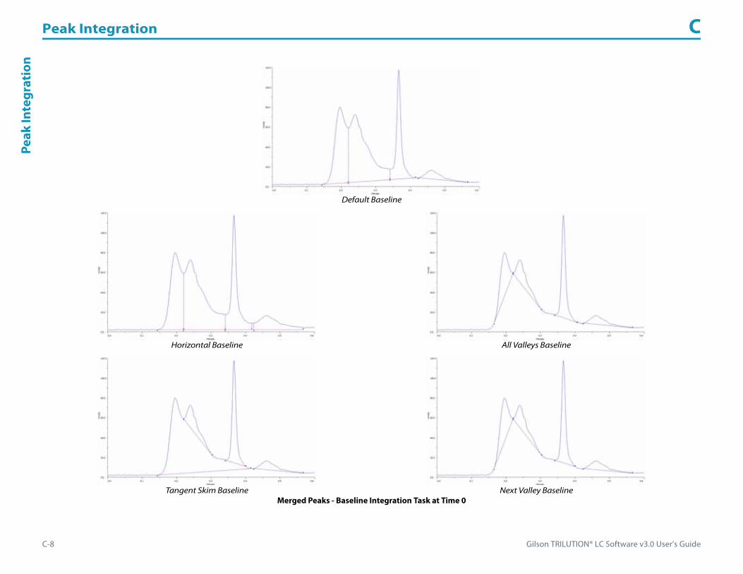
Peak Integration C
C-8 Gilson TRILUTION® LC Software v3.0 User’s Guide
Peak
Inte
grat
ion
Default Baseline
Horizontal Baseline All Valleys Baseline
Tangent Skim Baseline Next Valley BaselineMerged Peaks - Baseline Integration Task at Time 0

Gilson TRILUTION® LC Software v3.0 User’s Guide D-1
Fraction Collection Techniques D
Fraction collection parameters are set in the Fraction Collection Settings task. Four fraction collection modes are available for selection: Slope, Level, Time, or Volume.
Fraction collection is based on the primary channel.
This appendix provides information about the following:
• How to Collect Fractions by Slope
• How to Collect Fractions by Level
• How to Collect Fractions by Time
• How to Collect Fractions by Volume
The following examples of how the collection region selection affects collection by slope are provided:
• Collect Heart of Peak
• Collect Front to APEX
• Collect APEX to Tail
• Collect APEX
Additionally, an example is provided for how to Coordinate Integration with Fraction Collection.
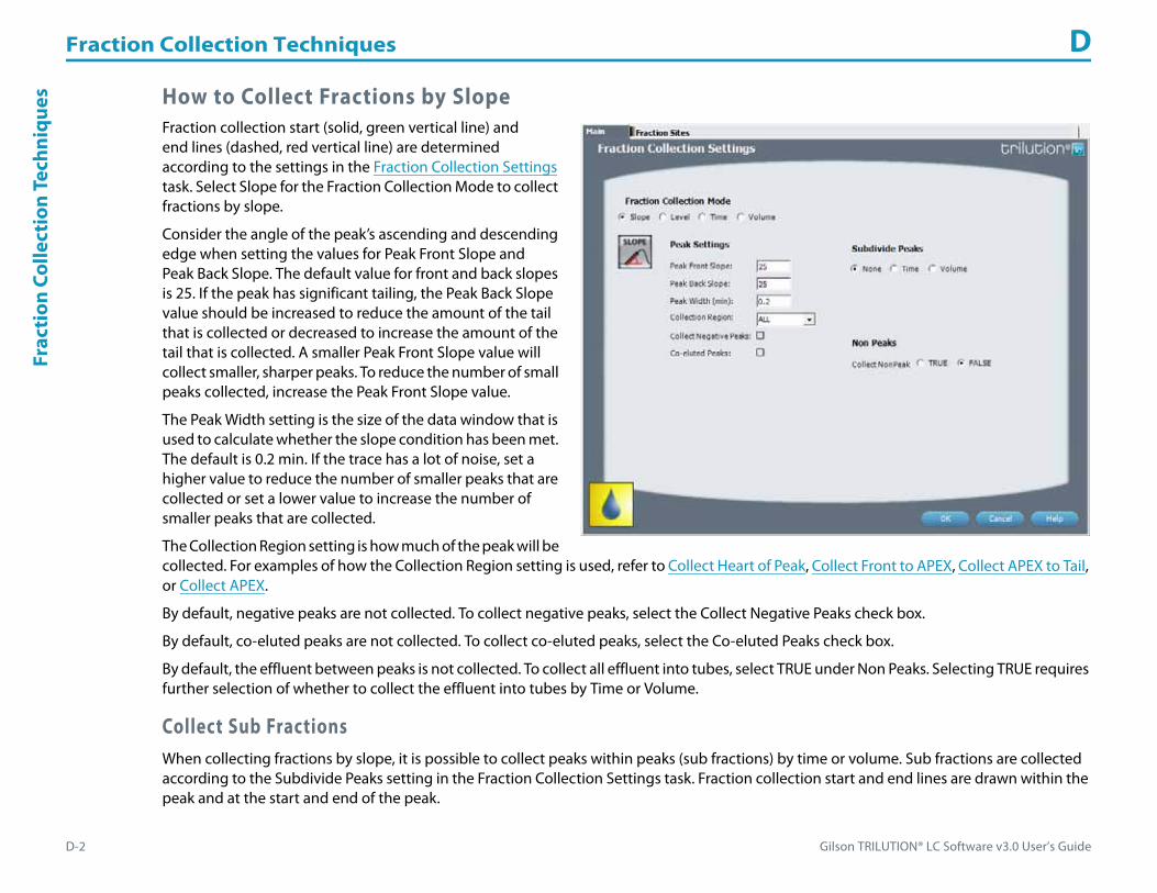
Fraction Collection Techniques D
D-2 Gilson TRILUTION® LC Software v3.0 User’s Guide
Frac
tion
Col
lect
ion
Tech
niqu
es How to Collect Fractions by SlopeFraction collection start (solid, green vertical line) and end lines (dashed, red vertical line) are determined according to the settings in the Fraction Collection Settings task. Select Slope for the Fraction Collection Mode to collect fractions by slope.
Consider the angle of the peak’s ascending and descending edge when setting the values for Peak Front Slope and Peak Back Slope. The default value for front and back slopes is 25. If the peak has significant tailing, the Peak Back Slope value should be increased to reduce the amount of the tail that is collected or decreased to increase the amount of the tail that is collected. A smaller Peak Front Slope value will collect smaller, sharper peaks. To reduce the number of small peaks collected, increase the Peak Front Slope value.
The Peak Width setting is the size of the data window that is used to calculate whether the slope condition has been met. The default is 0.2 min. If the trace has a lot of noise, set a higher value to reduce the number of smaller peaks that are collected or set a lower value to increase the number of smaller peaks that are collected.
The Collection Region setting is how much of the peak will be collected. For examples of how the Collection Region setting is used, refer to Collect Heart of Peak, Collect Front to APEX, Collect APEX to Tail, or Collect APEX.
By default, negative peaks are not collected. To collect negative peaks, select the Collect Negative Peaks check box.
By default, co-eluted peaks are not collected. To collect co-eluted peaks, select the Co-eluted Peaks check box.
By default, the effluent between peaks is not collected. To collect all effluent into tubes, select TRUE under Non Peaks. Selecting TRUE requires further selection of whether to collect the effluent into tubes by Time or Volume.
Collect Sub FractionsWhen collecting fractions by slope, it is possible to collect peaks within peaks (sub fractions) by time or volume. Sub fractions are collected according to the Subdivide Peaks setting in the Fraction Collection Settings task. Fraction collection start and end lines are drawn within the peak and at the start and end of the peak.
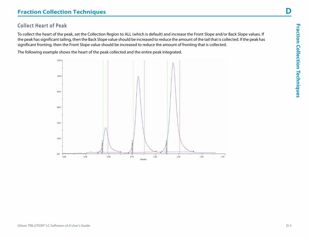
Gilson TRILUTION® LC Software v3.0 User’s Guide D-3
Fraction Collection Techniques DFraction Collection Techniques
Collect Heart of PeakTo collect the heart of the peak, set the Collection Region to ALL (which is default) and increase the Front Slope and/or Back Slope values. If the peak has significant tailing, then the Back Slope value should be increased to reduce the amount of the tail that is collected. If the peak has significant fronting, then the Front Slope value should be increased to reduce the amount of fronting that is collected.
The following example shows the heart of the peak collected and the entire peak integrated.

Fraction Collection Techniques D
D-4 Gilson TRILUTION® LC Software v3.0 User’s Guide
Frac
tion
Col
lect
ion
Tech
niqu
es Collect Front to APEXTo collect from the Front Slope value to the highest point of the peak, set the Collection Region to Front APEX.
The following example shows the front of the peak to the APEX collected by setting the Collection Region to Front APEX.
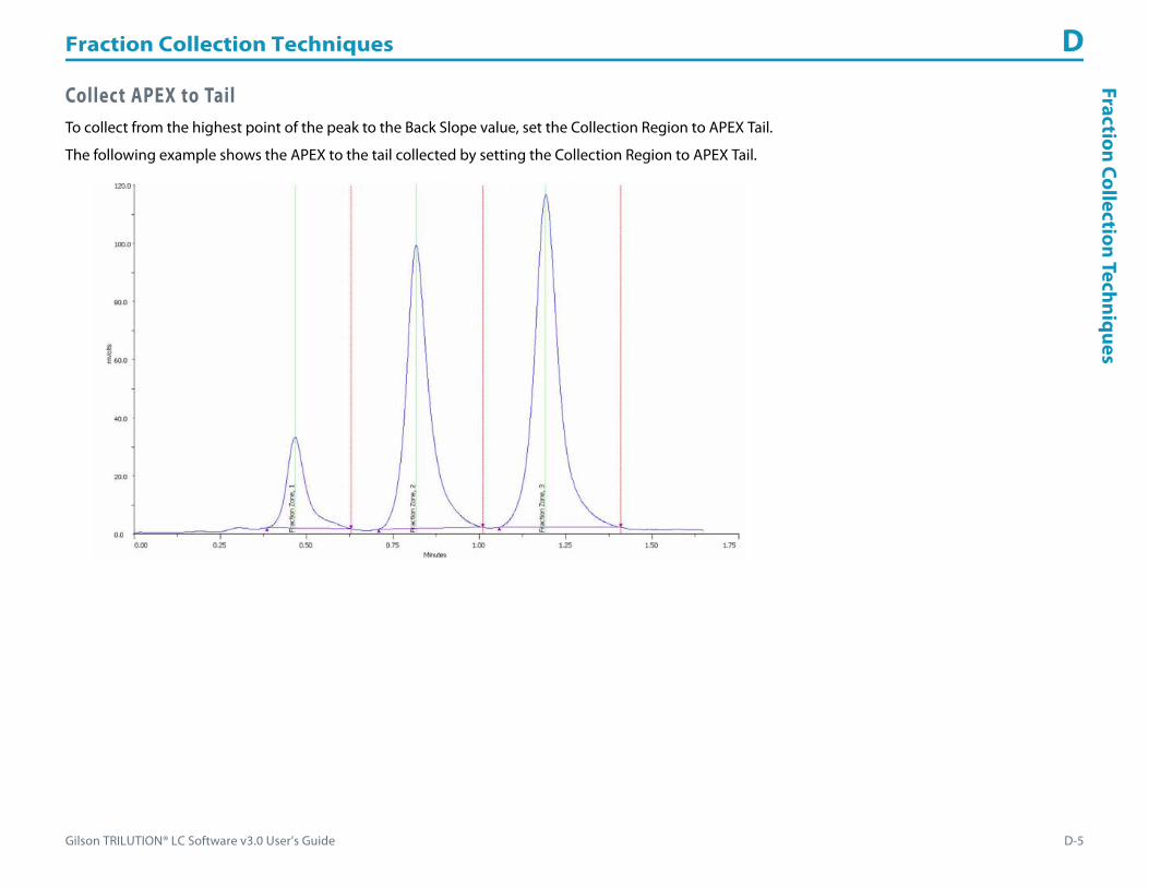
Gilson TRILUTION® LC Software v3.0 User’s Guide D-5
Fraction Collection Techniques DFraction Collection Techniques
Collect APEX to TailTo collect from the highest point of the peak to the Back Slope value, set the Collection Region to APEX Tail.
The following example shows the APEX to the tail collected by setting the Collection Region to APEX Tail.

Fraction Collection Techniques D
D-6 Gilson TRILUTION® LC Software v3.0 User’s Guide
Frac
tion
Col
lect
ion
Tech
niqu
es Collect APEXTo collect the entire peak, but advance to the next tube at the APEX, set the Collection Region to APEX.
The following example shows the peak being collected into two tubes with the valve switching and the collector advancing to the next tube at the APEX by setting the Collection Region to APEX.

Gilson TRILUTION® LC Software v3.0 User’s Guide D-7
Fraction Collection Techniques DFraction Collection Techniques
How to Collect Fractions by LevelFraction collection start (solid, green vertical line) and end lines (dashed, red vertical line) are determined according to the settings in the Fraction Collection Settings task. Select Level for the Fraction Collection Mode to collect fractions by level.
When collecting by level, indicate in the Peak Level field the value above which all peaks will be collected.
By default, negative peaks are not collected. To collect negative peaks, select the Collect Negative Peaks check box.
By default, the effluent between peaks is not collected. To collect all effluent into tubes, select TRUE under Non Peaks. Selecting TRUE requires further selection of whether to collect the effluent into tubes by time or volume.
Collect Sub FractionsWhen collecting fractions by level, it is possible to collect peaks within peaks (sub fractions) by time or volume. Sub fractions are collected according to the Subdivide Peaks setting in the Fraction Collection Settings task. Fraction collection start and end lines are drawn within the peak and at the start and end of the peak.

Fraction Collection Techniques D
D-8 Gilson TRILUTION® LC Software v3.0 User’s Guide
Frac
tion
Col
lect
ion
Tech
niqu
es How to Collect Fractions by TimeFraction collection start (solid, green vertical line) and end lines (dashed, red vertical line) are determined according to the settings in the Fraction Collection Settings task. Select Time for the Fraction Collection Mode to collect fractions by time. Selecting Time requires an entry in the Time per Tube field indicating how long to dispense at each tube.
Fraction Collection Settings Task Properties - Time Selected
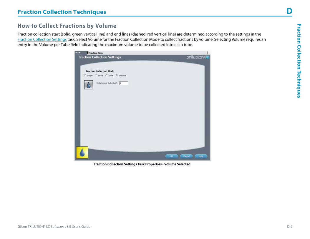
Gilson TRILUTION® LC Software v3.0 User’s Guide D-9
Fraction Collection Techniques DFraction Collection Techniques
How to Collect Fractions by VolumeFraction collection start (solid, green vertical line) and end lines (dashed, red vertical line) are determined according to the settings in the Fraction Collection Settings task. Select Volume for the Fraction Collection Mode to collect fractions by volume. Selecting Volume requires an entry in the Volume per Tube field indicating the maximum volume to be collected into each tube.
Fraction Collection Settings Task Properties - Volume Selected

Fraction Collection Techniques D
D-10 Gilson TRILUTION® LC Software v3.0 User’s Guide
Frac
tion
Col
lect
ion
Tech
niqu
es Coordinate Integration with Fraction CollectionFor integration and fraction collection to occur at the same time, use the same Front Slope values in the Fraction Collection Settings task as in the Analysis Settings task and also the same Back Slope values in the Fraction Collection Settings task as in the Analysis Settings task.
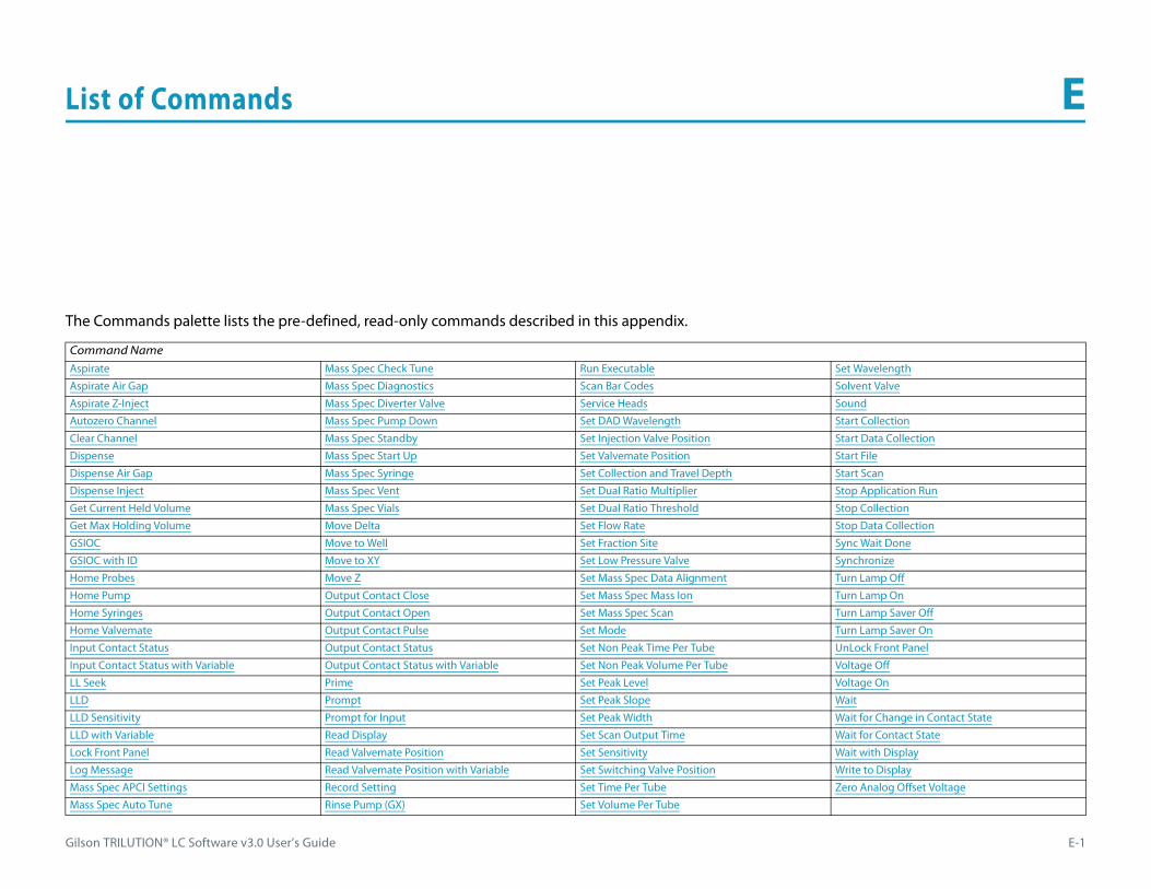
Gilson TRILUTION® LC Software v3.0 User’s Guide E-1
List of Commands E
The Commands palette lists the pre-defined, read-only commands described in this appendix.
Command NameAspirate Mass Spec Check Tune Run Executable Set Wavelength
Aspirate Air Gap Mass Spec Diagnostics Scan Bar Codes Solvent Valve
Aspirate Z-Inject Mass Spec Diverter Valve Service Heads Sound
Autozero Channel Mass Spec Pump Down Set DAD Wavelength Start Collection
Clear Channel Mass Spec Standby Set Injection Valve Position Start Data Collection
Dispense Mass Spec Start Up Set Valvemate Position Start File
Dispense Air Gap Mass Spec Syringe Set Collection and Travel Depth Start Scan
Dispense Inject Mass Spec Vent Set Dual Ratio Multiplier Stop Application Run
Get Current Held Volume Mass Spec Vials Set Dual Ratio Threshold Stop Collection
Get Max Holding Volume Move Delta Set Flow Rate Stop Data Collection
GSIOC Move to Well Set Fraction Site Sync Wait Done
GSIOC with ID Move to XY Set Low Pressure Valve Synchronize
Home Probes Move Z Set Mass Spec Data Alignment Turn Lamp Off
Home Pump Output Contact Close Set Mass Spec Mass Ion Turn Lamp On
Home Syringes Output Contact Open Set Mass Spec Scan Turn Lamp Saver Off
Home Valvemate Output Contact Pulse Set Mode Turn Lamp Saver On
Input Contact Status Output Contact Status Set Non Peak Time Per Tube UnLock Front Panel
Input Contact Status with Variable Output Contact Status with Variable Set Non Peak Volume Per Tube Voltage Off
LL Seek Prime Set Peak Level Voltage On
LLD Prompt Set Peak Slope Wait
LLD Sensitivity Prompt for Input Set Peak Width Wait for Change in Contact State
LLD with Variable Read Display Set Scan Output Time Wait for Contact State
Lock Front Panel Read Valvemate Position Set Sensitivity Wait with Display
Log Message Read Valvemate Position with Variable Set Switching Valve Position Write to Display
Mass Spec APCI Settings Record Setting Set Time Per Tube Zero Analog Offset Voltage
Mass Spec Auto Tune Rinse Pump (GX) Set Volume Per Tube

List of Commands E
E-2 Gilson TRILUTION® LC Software v3.0 User’s Guide
Asp
irat
e AspirateThis command draws liquid.
Aspirate Air GapThis command aspirates the specified volume of air at the specified rate using the specified syringe. This command is used only on pumps to aspirate the specified air volume.
Aspirate Properties
Property Name Brief Description Default Value
Instrument Name The instrument that the command will affect. #Pump
Synchronize Select ON and commands will be executed only after the previous command issued completes. Select OFF and commands will be executed at the same time.
ON
LH Instrument The liquid handler that the command will affect. #Liquid Handler
Syringe ID Not used. ALL
Valve Position The desired position of the dilutor valve. Select Gas, Probe, or Reservoir. PROBE
Sample Volume The amount of sample to aspirate. The total of all volumes cannot exceed the syringe or transfer tubing capacity. 100 μL
Extra Volume An additional volume to the Sample volume aspirated. It ensures that the actual volume of liquid to be transferred is not contaminated, and acts as an extra buffer between the air gap/reservoir solvent and the Sample Volume. 0 μL
Flow Rate The speed at which the volume moves into the probe. 1.5 mL/min
Use LLFUsed only when Valve Position = PROBE is selected; select TRUE and the probe will follow the liquid down as it is aspirated. The Z Option must be set to AUTO CALCULATE and initial volumes must be set in the Sample List to use this option.
Select FALSE and the probe will not follow the liquid down as it is aspirated.FALSE
Aspirate Properties
Aspirate Air Gap Properties
Property Name Brief Description Default Value
Instrument Name The instrument that the command will affect. #Pump
Synchronize Select ON and commands will be executed only after the previous command issued completes. Select OFF and commands will be executed at the same time. ON
Syringe ID Not used. ALL
Air Gap Volume The quantity of an air gap. The total of all volumes cannot exceed the syringe or transfer tubing capacity. 100 μL
Air Gap Flow Rate The speed at which the Air Gap Volume moves into the probe. 0.3 mL/min
Aspirate Air Gap Properties
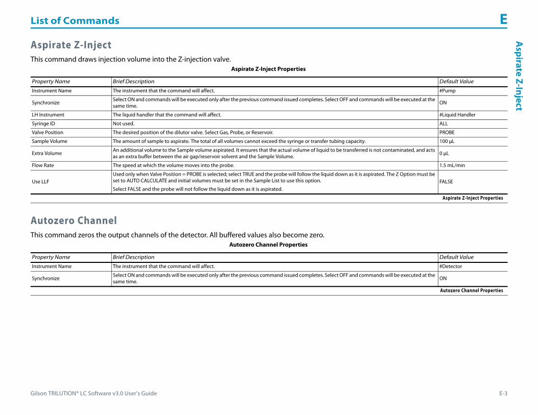
Gilson TRILUTION® LC Software v3.0 User’s Guide E-3
List of Commands EA
spirate Z-Inject
Aspirate Z-InjectThis command draws injection volume into the Z-injection valve.
Autozero ChannelThis command zeros the output channels of the detector. All buffered values also become zero.
Aspirate Z-Inject Properties
Property Name Brief Description Default Value
Instrument Name The instrument that the command will affect. #Pump
Synchronize Select ON and commands will be executed only after the previous command issued completes. Select OFF and commands will be executed at the same time.
ON
LH Instrument The liquid handler that the command will affect. #Liquid Handler
Syringe ID Not used. ALL
Valve Position The desired position of the dilutor valve. Select Gas, Probe, or Reservoir. PROBE
Sample Volume The amount of sample to aspirate. The total of all volumes cannot exceed the syringe or transfer tubing capacity. 100 μL
Extra Volume An additional volume to the Sample volume aspirated. It ensures that the actual volume of liquid to be transferred is not contaminated, and acts as an extra buffer between the air gap/reservoir solvent and the Sample Volume. 0 μL
Flow Rate The speed at which the volume moves into the probe. 1.5 mL/min
Use LLFUsed only when Valve Position = PROBE is selected; select TRUE and the probe will follow the liquid down as it is aspirated. The Z Option must be set to AUTO CALCULATE and initial volumes must be set in the Sample List to use this option.
Select FALSE and the probe will not follow the liquid down as it is aspirated.FALSE
Aspirate Z-Inject Properties
Autozero Channel Properties
Property Name Brief Description Default Value
Instrument Name The instrument that the command will affect. #Detector
Synchronize Select ON and commands will be executed only after the previous command issued completes. Select OFF and commands will be executed at the same time. ON
Autozero Channel Properties

List of Commands E
E-4 Gilson TRILUTION® LC Software v3.0 User’s Guide
Clea
r Cha
nnel Clear Channel
This command clears the FIFO for the selected analog input channel on the 506C System Interface.
DispenseThis command dispenses the specified amount sample volume and extra volume.
Clear Channel Properties
Property Name Brief Description Default Value
Instrument Name The instrument that the command will affect. #Contacts
Synchronize Select ON and commands will be executed only after the previous command issued completes. Select OFF and commands will be executed at the same time.
ON
Channel The analog input channel to clear. Valid range is A–D (up to four at once). A
Clear Channel Properties
Dispense Properties
Property Name Brief Description Default Value
Instrument Name The instrument that the command will affect. #Pump
Synchronize Select ON and commands will be executed only after the previous command issued completes.
Select OFF and commands will be executed at the same time.ON
LH Instrument The liquid handler that the command will affect. #Liquid Handler
Syringe ID Not used. ALL
Sample Volume The amount of sample to dispense. The total of all volumes cannot exceed the syringe or transfer tubing capacity. 100 μL
Extra Volume An additional volume to the first volume dispensed. It ensures that the actual volume of liquid to be transferred is not contaminated, and acts as an extra buffer between the air gap/reservoir solvent and the Volume. 0 μL
Flow Rate The speed at which the volume moves out of the probe. 1.5 mL/min
Use LLFUsed only when Valve Position = PROBE is selected; select TRUE and the probe will follow the liquid up as it is dispensed. The Z Option must be set to AUTO CALCULATE and initial volumes must be set in the sample list to use this option.
Select FALSE and the probe will not follow the liquid up as it is dispensed.FALSE
Solvent Valve PositionDesired position of the solvent selection valve on the Solvent System. Valid range is 1–6.
The position designated for waste cannot be used for a solvent.2
Dispense Properties

Gilson TRILUTION® LC Software v3.0 User’s Guide E-5
List of Commands ED
ispense Air G
ap
Dispense Air GapThis command delivers an air gap.
Dispense InjectThis command delivers injection volume into the injection port.
Dispense Air Gap Properties
Property Name Brief Description Default Value
Instrument Name The instrument that the command will affect. #Pump
Synchronize Select ON and commands will be executed only after the previous command issued completes. Select OFF and commands will be executed at the same time.
ON
Syringe ID Not used. ALL
Air Gap Volume The quantity of an air gap. The total of all volumes cannot exceed the syringe or transfer tubing capacity. 100 μL
Air Gap Flow Rate The speed at which the Air Gap Volume moves out of the probe. 1.5 mL/min
Solvent Valve PositionDesired position of the solvent selection valve on the Solvent System. Valid range is 1–6.
The position designated for waste cannot be used for a solvent.2
Dispense Air Gap Properties
Dispense Inject Properties
Property Name Brief Description Default Value
Instrument Name The instrument that the command will affect. #Pump
Synchronize Select ON and commands will be executed only after the previous command issued completes. Select OFF and commands will be executed at the same time. ON
LH Instrument The liquid handler that the command will affect. #Liquid Handler
Syringe ID Not used. ALL
Sample Volume The amount of sample to dispense. The total of all volumes cannot exceed the syringe or transfer tubing capacity. 100 μL
Extra Volume An additional volume to the first volume dispensed. It ensures that the actual volume of liquid to be transferred is not contaminated, and acts as an extra buffer between the air gap/reservoir solvent and the Volume. 0 μL
Flow Rate The speed at which the volume moves out of the probe. 1.5 mL/min
Use LLFUsed only when Valve Position = PROBE is selected; select TRUE and the probe will follow the liquid up as it is dispensed. The Z Option must be set to AUTO CALCULATE and initial volumes must be set in the Sample List to use this option.
Select FALSE and the probe will not follow the liquid up as it is dispensed.FALSE
Solvent Valve PositionDesired position of the solvent selection valve on the Solvent System. Valid range is 1–6.
The position designated for waste cannot be used for a solvent.2
Dispense Inject Properties

List of Commands E
E-6 Gilson TRILUTION® LC Software v3.0 User’s Guide
Get
Cur
rent
Hel
d Vo
lum
e Get Current Held VolumeThis command queries the software for the volume held in the syringe (if dilutor is present) or transfer tubing.
Get Max Holding Volume This command queries the software for the syringe capacity (if dilutor is present) or transfer tubing volume.
GSIOCThis command sends a GSIOC command to the specified instrument.
Get Current Held Volume Properties
Property Name Brief Description Default Value
Instrument Name The instrument that the command will affect. #Pump
Synchronize Select ON and commands will be executed only after the previous command issued completes. Select OFF and commands will be executed at the same time.
ON
Read in Variable Used as a variable for a response coming from the instrument. 0 μL
Get Current Held Volume Properties
Get Max Holding Volume Properties
Property Name Brief Description Default Value
Instrument Name The instrument that the command will affect. #Pump
Synchronize Select ON and commands will be executed only after the previous command issued completes. Select OFF and commands will be executed at the same time. ON
Read in Variable Used as a variable for a response coming from the instrument. 0 μL
Get Max Holding Volume Properties
GSIOC Properties
Property Name Brief Description Default Value
Instrument The instrument that the command will affect.
Synchronize Select ON and commands will be executed only after the previous command issued completes. Select OFF and commands will be executed at the same time. ON
Command The string that sends an instruction to the Instrument.
Type The command type: BUFFERED or IMMEDIATE. IMMEDIATE
Read in Variable Used as a variable for a response coming from the instrument.
GSIOC Properties

Gilson TRILUTION® LC Software v3.0 User’s Guide E-7
List of Commands EG
SIOC w
ith ID
GSIOC with IDThis command sends a GSIOC command to an instrument at the specified unit ID.
Home ProbesThe command homes the X/Y/Z on the specified liquid handler.
Home PumpThis command homes the pump on the GX solvent system.
GSIOC with ID Properties
Property Name Brief Description Default Value
Unit ID The unit ID of the instrument that the command will affect.
SynchronizeSelect ON and commands will be executed only after the previous command issued completes.
Select OFF and commands will be executed at the same time.ON
Command The string that sends an instruction to the Unit ID.
Type The command type: BUFFERED or IMMEDIATE. IMMEDIATE
Read in Variable Used as a variable for a response coming from the instrument.
GSIOC with ID Properties
Home Probes Properties
Property Name Brief Description Default Value
Instrument Name The instrument that the command will affect. #Liquid Handler
Synchronize Select ON and commands will be executed only after the previous command issued completes. Select OFF and commands will be executed at the same time. ON
Home Probes Properties
Home Pump Properties
Property Name Brief Description Default Value
Instrument Name The instrument that the command will affect. #Pump
Synchronize Select ON and commands will be executed only after the previous command issued completes. Select OFF and commands will be executed at the same time. ON
Home Pump Properties

List of Commands E
E-8 Gilson TRILUTION® LC Software v3.0 User’s Guide
Hom
e Sy
ring
es Home SyringesThis command homes the external dilutor or the dilutor on a liquid handler.
Home ValvemateThis command homes the valve position on a VALVEMATE or VALVEMATE II.
Input Contact StatusThis command queries the status of the specified contact input for the specified instrument.
Home Syringes Properties
Property Name Brief Description Default Value
Instrument Name The instrument that the command will affect. #Pump
Synchronize Select ON and commands will be executed only after the previous command issued completes. Select OFF and commands will be executed at the same time.
ON
Home Syringes Properties
Home Valvemate Properties
Property Name Brief Description Default Value
Instrument Name The instrument that the command will affect. #Valvemate
Synchronize Select ON and commands will be executed only after the previous command issued completes. Select OFF and commands will be executed at the same time. ON
Home Valvemate Properties
Input Contact Status Properties
Property Name Brief Description Default Value
Instrument Name The instrument that the command will affect. #Liquid Handler
Synchronize Select ON and commands will be executed only after the previous command issued completes. Select OFF and commands will be executed at the same time. ON
Contact ID The input contact being queried. Valid range A–E. A
Input Contact Status Properties
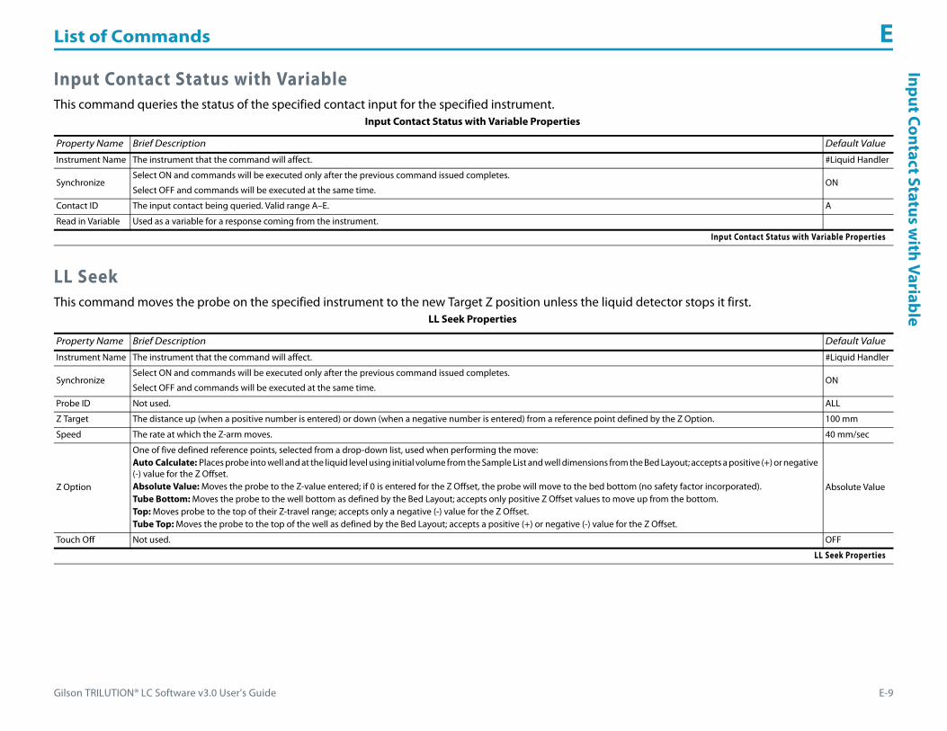
Gilson TRILUTION® LC Software v3.0 User’s Guide E-9
List of Commands EInput Contact Status w
ith Variable
Input Contact Status with VariableThis command queries the status of the specified contact input for the specified instrument.
LL SeekThis command moves the probe on the specified instrument to the new Target Z position unless the liquid detector stops it first.
Input Contact Status with Variable Properties
Property Name Brief Description Default Value
Instrument Name The instrument that the command will affect. #Liquid Handler
SynchronizeSelect ON and commands will be executed only after the previous command issued completes.
Select OFF and commands will be executed at the same time.ON
Contact ID The input contact being queried. Valid range A–E. A
Read in Variable Used as a variable for a response coming from the instrument.
Input Contact Status with Variable Properties
LL Seek Properties
Property Name Brief Description Default Value
Instrument Name The instrument that the command will affect. #Liquid Handler
Synchronize Select ON and commands will be executed only after the previous command issued completes.
Select OFF and commands will be executed at the same time.ON
Probe ID Not used. ALL
Z Target The distance up (when a positive number is entered) or down (when a negative number is entered) from a reference point defined by the Z Option. 100 mm
Speed The rate at which the Z-arm moves. 40 mm/sec
Z Option
One of five defined reference points, selected from a drop-down list, used when performing the move:Auto Calculate: Places probe into well and at the liquid level using initial volume from the Sample List and well dimensions from the Bed Layout; accepts a positive (+) or negative (-) value for the Z Offset.Absolute Value: Moves the probe to the Z-value entered; if 0 is entered for the Z Offset, the probe will move to the bed bottom (no safety factor incorporated).Tube Bottom: Moves the probe to the well bottom as defined by the Bed Layout; accepts only positive Z Offset values to move up from the bottom.Top: Moves probe to the top of their Z-travel range; accepts only a negative (-) value for the Z Offset.Tube Top: Moves the probe to the top of the well as defined by the Bed Layout; accepts a positive (+) or negative (-) value for the Z Offset.
Absolute Value
Touch Off Not used. OFF
LL Seek Properties

List of Commands E
E-10 Gilson TRILUTION® LC Software v3.0 User’s Guide
LLD LLD
This command detects the liquid level for the specified instrument and is used for the following circumstances:• To move the probe in the Z direction depending on the height of the liquid in the well.• To move the probe just to the top of the sample. This can be achieved through LLF command also.• To aspirate only on confirming the presence of the sample in the well.
LLD SensitivityThis command detects liquid when the Liquid Level Detection is used. A low setting is the most sensitive and higher settings are less sensitive.
LLD Properties
Property Name Brief Description Default Value
Instrument Name The instrument that the command will affect. #Liquid Handler
Synchronize Select ON and commands will be executed only after the previous command issued completes. Select OFF and commands will be executed at the same time. ON
Probe ID Not used. ALL
LLD Properties
LLD Sensitivity Properties
Property Name Brief Description Default Value
Instrument Name The instrument that the command will affect. #Liquid Handler
Synchronize Select ON and commands will be executed only after the previous command issued completes. Select OFF and commands will be executed at the same time. ON
Probe ID Not used. ALL
Sensitivity Sensitivity is a percent (0–100%) used to detect liquid when Liquid Level Detection is used. A low setting is the most sensitive and higher settings are less sensitive. 0
LLD Sensitivity Properties
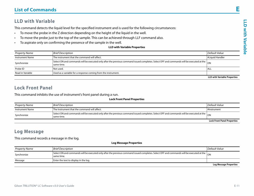
Gilson TRILUTION® LC Software v3.0 User’s Guide E-11
List of Commands ELLD
with Variable
LLD with VariableThis command detects the liquid level for the specified instrument and is used for the following circumstances:• To move the probe in the Z direction depending on the height of the liquid in the well.• To move the probe just to the top of the sample. This can be achieved through LLF command also.• To aspirate only on confirming the presence of the sample in the well.
Lock Front PanelThis command inhibits the use of instrument’s front panel during a run.
Log MessageThis command records a message in the log.
LLD with Variable Properties
Property Name Brief Description Default Value
Instrument Name The instrument that the command will affect. #Liquid Handler
Synchronize Select ON and commands will be executed only after the previous command issued completes. Select OFF and commands will be executed at the same time. ON
Probe ID Not used. ALL
Read in Variable Used as a variable for a response coming from the instrument.
LLD with Variable Properties
Lock Front Panel Properties
Property Name Brief Description Default Value
Instrument Name The Instrument that the command will affect. #Instrument
Synchronize Select ON and commands will be executed only after the previous command issued completes. Select OFF and commands will be executed at the same time. ON
Lock Front Panel Properties
Log Message Properties
Property Name Brief Description Default Value
Synchronize Select ON and commands will be executed only after the previous command issued completes. Select OFF and commands will be executed at the same time. ON
Message Enter the text to display in the log.
Log Message Properties
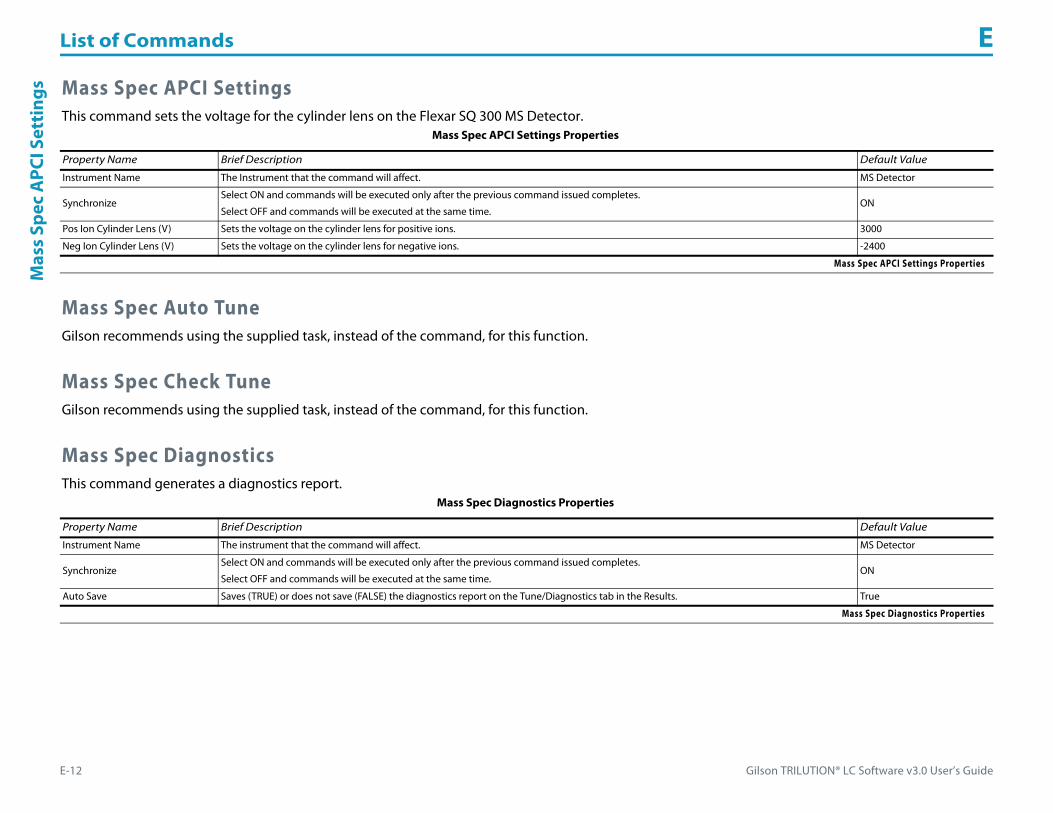
List of Commands E
E-12 Gilson TRILUTION® LC Software v3.0 User’s Guide
Mas
s Sp
ec A
PCI S
etti
ngs Mass Spec APCI Settings
This command sets the voltage for the cylinder lens on the Flexar SQ 300 MS Detector.
Mass Spec Auto TuneGilson recommends using the supplied task, instead of the command, for this function.
Mass Spec Check TuneGilson recommends using the supplied task, instead of the command, for this function.
Mass Spec DiagnosticsThis command generates a diagnostics report.
Mass Spec APCI Settings Properties
Property Name Brief Description Default Value
Instrument Name The Instrument that the command will affect. MS Detector
SynchronizeSelect ON and commands will be executed only after the previous command issued completes.
Select OFF and commands will be executed at the same time.ON
Pos Ion Cylinder Lens (V) Sets the voltage on the cylinder lens for positive ions. 3000
Neg Ion Cylinder Lens (V) Sets the voltage on the cylinder lens for negative ions. -2400
Mass Spec APCI Settings Properties
Mass Spec Diagnostics Properties
Property Name Brief Description Default Value
Instrument Name The instrument that the command will affect. MS Detector
SynchronizeSelect ON and commands will be executed only after the previous command issued completes.
Select OFF and commands will be executed at the same time.ON
Auto Save Saves (TRUE) or does not save (FALSE) the diagnostics report on the Tune/Diagnostics tab in the Results. True
Mass Spec Diagnostics Properties

Gilson TRILUTION® LC Software v3.0 User’s Guide E-13
List of Commands EM
ass Spec Diverter Valve
Mass Spec Diverter ValveThis command switches the diverter valve on the Flexar SQ 300 MS Detector.
Mass Spec Pump DownThis command pumps down the Flexar SQ 300 MS Detector.
Mass Spec StandbyGilson recommends using the supplied task, instead of the command, for this function.
Mass Spec Start UpGilson recommends using the supplied task, instead of the command, for this function.
Mass Spec Diverter Valve Properties
Property Name Brief Description Default Value
Instrument Name The instrument that the command will affect. MS Detector
SynchronizeSelect ON and commands will be executed only after the previous command issued completes.
Select OFF and commands will be executed at the same time.ON
Diverter Valve PositionSelect position 1 or position 2.
Using the suggested plumbing connections, position 1 would be Sample and position 2 would be Tune Mix.1
Mass Spec Diverter Valve Properties
Mass Spec Pump Down Properties
Property Name Brief Description Default Value
Instrument Name The instrument that the command will affect. MS Detector
SynchronizeSelect ON and commands will be executed only after the previous command issued completes.
Select OFF and commands will be executed at the same time.ON
Mass Spec Pump Down Properties
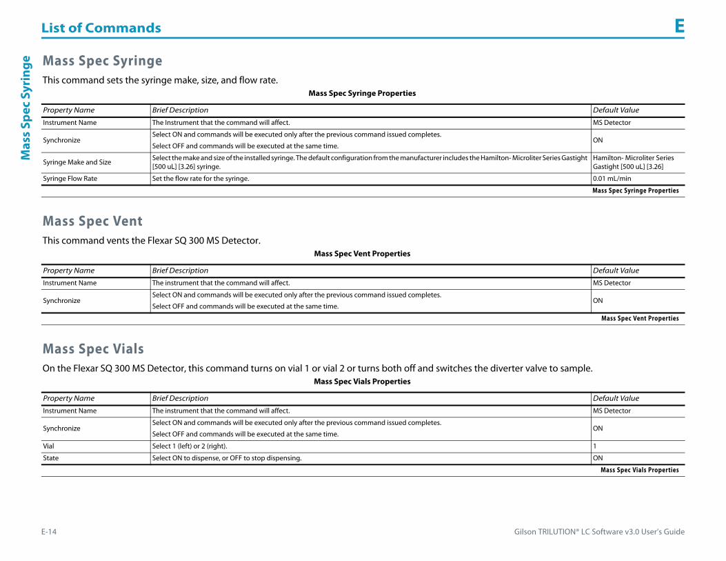
List of Commands E
E-14 Gilson TRILUTION® LC Software v3.0 User’s Guide
Mas
s Sp
ec S
yrin
ge Mass Spec SyringeThis command sets the syringe make, size, and flow rate.
Mass Spec VentThis command vents the Flexar SQ 300 MS Detector.
Mass Spec VialsOn the Flexar SQ 300 MS Detector, this command turns on vial 1 or vial 2 or turns both off and switches the diverter valve to sample.
Mass Spec Syringe Properties
Property Name Brief Description Default Value
Instrument Name The Instrument that the command will affect. MS Detector
SynchronizeSelect ON and commands will be executed only after the previous command issued completes.
Select OFF and commands will be executed at the same time.ON
Syringe Make and Size Select the make and size of the installed syringe. The default configuration from the manufacturer includes the Hamilton- Microliter Series Gastight [500 uL] [3.26] syringe.
Hamilton- Microliter Series Gastight [500 uL] [3.26]
Syringe Flow Rate Set the flow rate for the syringe. 0.01 mL/min
Mass Spec Syringe Properties
Mass Spec Vent Properties
Property Name Brief Description Default Value
Instrument Name The instrument that the command will affect. MS Detector
SynchronizeSelect ON and commands will be executed only after the previous command issued completes.
Select OFF and commands will be executed at the same time.ON
Mass Spec Vent Properties
Mass Spec Vials Properties
Property Name Brief Description Default Value
Instrument Name The instrument that the command will affect. MS Detector
SynchronizeSelect ON and commands will be executed only after the previous command issued completes.
Select OFF and commands will be executed at the same time.ON
Vial Select 1 (left) or 2 (right). 1
State Select ON to dispense, or OFF to stop dispensing. ON
Mass Spec Vials Properties

Gilson TRILUTION® LC Software v3.0 User’s Guide E-15
List of Commands EM
ove Delta
Move DeltaThis command moves the arm in the X- and Y-direction as specified. This is used if the probe has to be moved to a position other than the center of the well. This command is used in the following circumstances:• Used in relatively large diameter wells to move from one position to another position within the well.• To move to different positions between the wells.
Move to WellThis command moves the Z-arm so that the probe will move to the specified well in the specified zone.
Move Delta Properties
Property Name Brief Description Default Value
Instrument Name The instrument that the command will affect. #Liquid Handler
Synchronize Select ON and commands will be executed only after the previous command issued completes. Select OFF and commands will be executed at the same time. ON
X DeltaSpecify the required displacement of the arm in the X-direction from the current position of the arm.
Positive number moves the arm to the right, from the current position. Negative number moves the arm to the left, from the current position.100 mm
Y DeltaSpecify the required displacement of the arm in the Y-direction from the current position of the arm.
Positive number moves the arm towards the front, from the current position. Negative number moves the arm backwards, from the current position.
100 mm
Reference Probe Not used. ALL
Move Delta Properties
Move to Well Properties
Property Name Brief Description Default Value
Instrument Name The instrument that the command will affect. #Liquid Handler
Synchronize Select ON and commands will be executed only after the previous command issued completes. Select OFF and commands will be executed at the same time. ON
Probe ID Not used. ALL
Zone Name The name of the zone to move to. Source Zone
Well Number This is the number of the well in the zone. 1
Move Option Not used. Center
Move to Well Properties

List of Commands E
E-16 Gilson TRILUTION® LC Software v3.0 User’s Guide
Mov
e to
XY Move to XY
This command moves the arm to an absolute X value and an absolute Y value.
Move ZThis command moves the probe on the specified instrument in the Z direction.
Move to XY Properties
Property Name Brief Description Default Value
Instrument Name The instrument that the command will affect. #Liquid Handler
Synchronize Select ON and commands will be executed only after the previous command issued completes. Select OFF and commands will be executed at the same time.
ON
X Target Specify the absolute X value that you want the arm to move to. 100 mm
Y Target Specify the absolute Y value that you want the arm to move to. 100 mm
Reference Probe Not used. ALL
Move to XY Properties
Move Z Properties
Property Name Brief Description Default Value
Instrument Name The instrument that the command will affect. #Liquid Handler
Synchronize Select ON and commands will be executed only after the previous command issued completes. Select OFF and commands will be executed at the same time. ON
Probe ID Not used. ALL
Z Target The distance up (when a positive number is entered) or down (when a negative number is entered) from a reference point defined by the Z Option. 100 mm
Speed The rate at which the Z-arm moves. 123 mm/sec
Z Option
One of five defined reference points, selected from a drop-down list, used when performing the move:Auto Calculate: Places probe into well and at the liquid level using initial volume from the sample list and well dimensions from the bed layout; accepts a positive (+) or negative (-) value for the Z Offset.Absolute Value: Moves the probe to the Z-value entered; if 0 is entered for the Z Offset, the probe will move to the bed bottom (no safety factor incorporated).Tube Bottom: Moves the probe to the well bottom as defined by the bed layout; accepts only positive Z Offset values to move up from the bottom.Top: Moves probe to the top of their Z-travel range; accepts only a negative (-) value for the Z Offset.Tube Top: Moves the probe to the top of the well as defined by the bed layout; accepts a positive (+) or negative (-) value for the Z Offset.
Absolute Value
Touch Off Not used. OFF
Move Z Properties
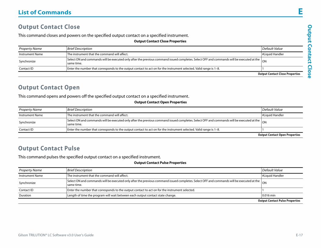
Gilson TRILUTION® LC Software v3.0 User’s Guide E-17
List of Commands EO
utput Contact Close
Output Contact CloseThis command closes and powers on the specified output contact on a specified instrument.
Output Contact OpenThis command opens and powers off the specified output contact on a specified instrument.
Output Contact PulseThis command pulses the specified output contact on a specified instrument.
Output Contact Close Properties
Property Name Brief Description Default Value
Instrument Name The instrument that the command will affect. #Liquid Handler
Synchronize Select ON and commands will be executed only after the previous command issued completes. Select OFF and commands will be executed at the same time.
ON
Contact ID Enter the number that corresponds to the output contact to act on for the instrument selected. Valid range is 1–8. 1
Output Contact Close Properties
Output Contact Open Properties
Property Name Brief Description Default Value
Instrument Name The instrument that the command will affect. #Liquid Handler
Synchronize Select ON and commands will be executed only after the previous command issued completes. Select OFF and commands will be executed at the same time. ON
Contact ID Enter the number that corresponds to the output contact to act on for the instrument selected. Valid range is 1–8. 1
Output Contact Open Properties
Output Contact Pulse Properties
Property Name Brief Description Default Value
Instrument Name The instrument that the command will affect. #Liquid Handler
Synchronize Select ON and commands will be executed only after the previous command issued completes. Select OFF and commands will be executed at the same time. ON
Contact ID Enter the number that corresponds to the output contact to act on for the instrument selected. 1
Duration Length of time the program will wait between each output contact state change. 0.016 min
Output Contact Pulse Properties

List of Commands E
E-18 Gilson TRILUTION® LC Software v3.0 User’s Guide
Out
put C
onta
ct S
tatu
s Output Contact StatusThis command queries the status of the specified contact output for the specified instrument.
Output Contact Status with VariableThis command queries the status of the specified contact output for the specified instrument.
PrimeThis command primes the syringe pump or transfer tubing with reservoir solvent.
Output Contact Status Properties
Property Name Brief Description Default Value
Instrument Name The instrument that the command will affect. #Liquid Handler
Synchronize Select ON and commands will be executed only after the previous command issued completes. Select OFF and commands will be executed at the same time.
ON
Contact ID The output contact being queried. Valid range is 1–8. 1
Output Contact Status Properties
Output Contact Status with Variable Properties
Property Name Brief Description Default Value
Instrument Name The instrument that the command will affect. #Liquid Handler
Synchronize Select ON and commands will be executed only after the previous command issued completes. Select OFF and commands will be executed at the same time. ON
Contact ID The output contact being queried. Valid range is 1–8. 1
Read in Variable Used as a variable for a response coming from the instrument.
Output Contact Status with Variable Properties
Prime Properties
Property Name Brief Description Default Value
Instrument Name The instrument that the command will affect. #Pump
Synchronize Select ON and commands will be executed only after the previous command issued completes. Select OFF and commands will be executed at the same time. ON
Flow Rate The speed at which the volume moves into the probe. 1.5 mL/min
Number of Cycles The number of times to repeat aspirating and dispensing. 1
Solvent Valve PositionDesired position of the solvent selection valve on the Solvent System. Valid range is 1–6.
The position designated for waste cannot be used for a solvent.2
Prime Properties
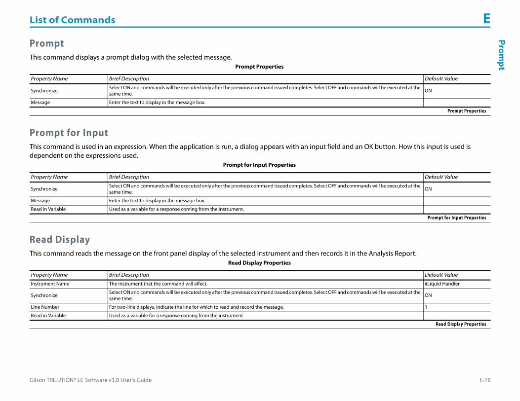
Gilson TRILUTION® LC Software v3.0 User’s Guide E-19
List of Commands EProm
pt
PromptThis command displays a prompt dialog with the selected message.
Prompt for InputThis command is used in an expression. When the application is run, a dialog appears with an input field and an OK button. How this input is used is dependent on the expressions used.
Read DisplayThis command reads the message on the front panel display of the selected instrument and then records it in the Analysis Report.
Prompt Properties
Property Name Brief Description Default Value
Synchronize Select ON and commands will be executed only after the previous command issued completes. Select OFF and commands will be executed at the same time. ON
Message Enter the text to display in the message box.
Prompt Properties
Prompt for Input Properties
Property Name Brief Description Default Value
Synchronize Select ON and commands will be executed only after the previous command issued completes. Select OFF and commands will be executed at the same time. ON
Message Enter the text to display in the message box.
Read in Variable Used as a variable for a response coming from the instrument.
Prompt for Input Properties
Read Display Properties
Property Name Brief Description Default Value
Instrument Name The instrument that the command will affect. #Liquid Handler
Synchronize Select ON and commands will be executed only after the previous command issued completes. Select OFF and commands will be executed at the same time. ON
Line Number For two-line displays, indicate the line for which to read and record the message. 1
Read in Variable Used as a variable for a response coming from the instrument.
Read Display Properties

List of Commands E
E-20 Gilson TRILUTION® LC Software v3.0 User’s Guide
Read
Val
vem
ate
Posi
tion Read Valvemate Position
This command reads the position of the switching valve and then records it in the log file.
Read Valvemate Position with VariableThis command reads the position of the switching valve and then records it in the log file.
Record SettingThis command queries the value of the selected setting and then records it in the analysis report.
Read Valvemate Position Properties
Property Name Brief Description Default Value
Instrument Name The instrument that the command will affect. #Valvemate
Synchronize Select ON and commands will be executed only after the previous command issued completes. Select OFF and commands will be executed at the same time.
ON
Read Valvemate Position Properties
Read Valvemate Position with Variable Properties
Property Name Brief Description Default Value
Instrument Name The instrument that the command will affect. #Valvemate
Synchronize Select ON and commands will be executed only after the previous command issued completes. Select OFF and commands will be executed at the same time. ON
Read in Variable Used as a variable for a response coming from the instrument.
Read Valvemate Position with Variable Properties
Record Setting Properties
Property Name Description Default Value
Instrument Name The detector that the command will affect. #Detector
Synchronize Select ON and commands will be executed only after the previous command issued completes. Select OFF and commands will be executed at the same time. ON
Setting
The options for settings which will be queried for a value are: Single WL, Single Sens. 1, Single Sens. 2, Single Peak Width, Dual WL 1, Dual WL 2, Dual Sens. 1, Dual Sens. 2, Dual Peak Width, Dual Ratio Multi., Dual Ratio Thres., Scan WL, Scan WL 1, Scan WL 2, Scan Sens. 1, Scan Sens. 2, Scan Sens. 3, ScanPeakWidth, ScanOut Time, Conc.Factor, Event Channel(s), AutoRange Channel(s), AutoRange Mult., GSIOC UnitID, Operation Mode, Lamp Saver, UV Lamp Alarm, Visible Lamp Alarm, Channel 1 Scale, Channel 1 OffSet, Channel 2 Scale, Channel 2 OffSet, Channel 3 Scale, and Channel 3 OffSet.
Single WL
Record Setting Properties
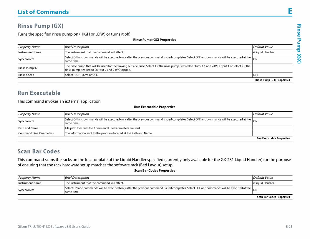
Gilson TRILUTION® LC Software v3.0 User’s Guide E-21
List of Commands ERinse Pum
p (GX)
Rinse Pump (GX)Turns the specified rinse pump on (HIGH or LOW) or turns it off.
Run ExecutableThis command invokes an external application.
Scan Bar CodesThis command scans the racks on the locator plate of the Liquid Handler specified (currently only available for the GX-281 Liquid Handler) for the purpose of ensuring that the rack hardware setup matches the software rack (Bed Layout) setup.
Rinse Pump (GX) Properties
Property Name Brief Description Default Value
Instrument Name The instrument that the command will affect. #Liquid Handler
Synchronize Select ON and commands will be executed only after the previous command issued completes. Select OFF and commands will be executed at the same time.
ON
Rinse Pump ID The rinse pump that will be used for the flowing outside rinse. Select 1 if the rinse pump is wired to Output 1 and 24V Output 1 or select 2 if the rinse pump is wired to Output 2 and 24V Output 2.
1
Rinse Speed Select HIGH, LOW, or OFF. OFF
Rinse Pump (GX) Properties
Run Executable Properties
Property Name Brief Description Default Value
Synchronize Select ON and commands will be executed only after the previous command issued completes. Select OFF and commands will be executed at the same time. ON
Path and Name File path to which the Command Line Parameters are sent.
Command Line Parameters The information sent to the program located at the Path and Name.
Run Executable Properties
Scan Bar Codes Properties
Property Name Brief Description Default Value
Instrument Name The instrument that the command will affect. #Liquid Handler
Synchronize Select ON and commands will be executed only after the previous command issued completes. Select OFF and commands will be executed at the same time. ON
Scan Bar Codes Properties

List of Commands E
E-22 Gilson TRILUTION® LC Software v3.0 User’s Guide
Serv
ice
Hea
ds Service HeadsThis command is used when replacing or servicing the pump heads.
Set DAD WavelengthThis command sets the DAD wavelengths to be monitored based on the Channel selected for the selected Detector.
Service Heads Properties
Property Name Description Default Value
Instrument Name The instrument that the command will affect. #Pump
Synchronize Select ON and commands will be executed only after the previous command issued completes. Select OFF and commands will be executed at the same time.
ON
Mount HeadsSelect TRUE to mount the heads.
Select FALSE move the pump head pistons to the dismount position.FALSE
Service Heads Properties
Set DAD Wavelength Properties
Property Name Brief Description Default Value
Instrument Name The instrument that the command will affect. #Detector
Synchronize Select ON and commands will be executed only after the previous command issued completes. Select OFF and commands will be executed at the same time. ON
Channel The channel for which wavelength and bandwidth properties will be set. 0
Wavelength
The wavelength at which chromatogram data will be extracted and displayed on-screen during the run.
Range for 171 Diode Array Detector:
[Wavelength (0.5 x WavelengthBW)] > 186 and [Wavelength + (0.5 x WavelengthBW)] < 723
Range for the 172 Diode Array Detector:
[Wavelength (0.5 x WavelengthBW)] > 186 and [Wavelength + (0.5 x WavelengthBW)] < 612
0 nm
WavelengthBW The number of wavelengths that TRILUTION will use in the chromatogram calculation for the wavelength. Optimizing the bandwidth improves the signal-to-noise ratio to obtain the optimum signal for peak detection. (Range 1–15 nm, range dependent on setting for Wavelength) 0 nm
Set DAD Wavelength Properties (Page 1 of 2)

Gilson TRILUTION® LC Software v3.0 User’s Guide E-23
List of Commands ESet Injection Valve Position
Set Injection Valve PositionThis command sets the injection valve position on the Injector to either LOAD or INJECT.
Set Valvemate PositionThis command sets the position of the switching valve.
Reference
The reference is used to correct for background noise and instabilities in the detector. Choose a reference that is close to the wavelength and in a region of non-absorbance.
Range for the 171 Diode Array Detector:
[Reference (0.5 x ReferenceBW)] > 186 and [Reference + (0.5 x ReferenceBW)] < 723
Range for the 172 Diode Array Detector:
[Reference (0.5 x ReferenceBW)] > 186 and [Reference + (0.5 x Reference BW)] < 612
0 nm
ReferenceBWThe ReferenceBW sets the number of wavelengths that TRILUTION will use in the chromatogram calculation for the reference. Optimizing the bandwidth improves the signal-to-noise ratio to obtain the optimum signal for peak detection. (Range 1–50 nm, range dependent on setting for Reference)
0 nm
Set DAD Wavelength Properties (Continued)
Property Name Brief Description Default Value
Set DAD Wavelength Properties (Page 2 of 2)
Set Injection Valve Position Properties
Property Name Brief Description Default Value
Instrument Name The instrument that the command will affect. #Injector
Synchronize Select ON and commands will be executed only after the previous command issued completes. Select OFF and commands will be executed at the same time. ON
Injection Valve Position Select from LOAD or INJECT. LOAD
Valve ID Valid range 1-8. 1
Set Injection Valve Position Properties
Set Valvemate Position Properties
Property Name Brief Description Default Value
Instrument Name The name used to identify the instrument that the command will affect. It must be typed exactly as it is in the Configuration. #Valvemate
PositionDesired position of the valve on the VALVEMATE.
Note: When using a 2-position valve on a VALVEMATE, choose 1 for position 0 or 2 for position 1.1
Synchronize Select ON and commands will be executed only after the previous command issued completes. Select OFF and commands will be executed at the same time.
ON
Set Valvemate Position Properties
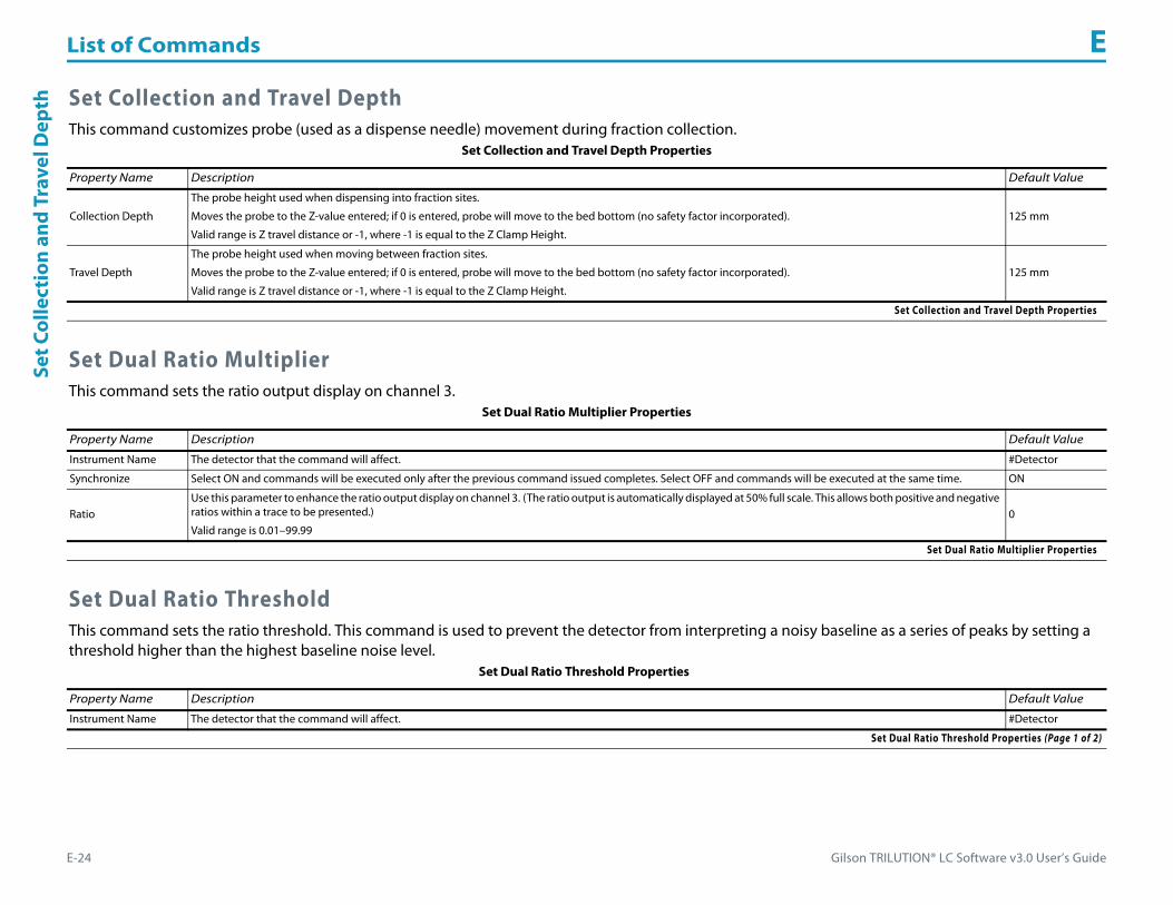
List of Commands E
E-24 Gilson TRILUTION® LC Software v3.0 User’s Guide
Set C
olle
ctio
n an
d Tr
avel
Dep
th Set Collection and Travel DepthThis command customizes probe (used as a dispense needle) movement during fraction collection.
Set Dual Ratio MultiplierThis command sets the ratio output display on channel 3.
Set Dual Ratio ThresholdThis command sets the ratio threshold. This command is used to prevent the detector from interpreting a noisy baseline as a series of peaks by setting a threshold higher than the highest baseline noise level.
Set Collection and Travel Depth Properties
Property Name Description Default Value
Collection Depth
The probe height used when dispensing into fraction sites.
Moves the probe to the Z-value entered; if 0 is entered, probe will move to the bed bottom (no safety factor incorporated).
Valid range is Z travel distance or -1, where -1 is equal to the Z Clamp Height.
125 mm
Travel Depth
The probe height used when moving between fraction sites.
Moves the probe to the Z-value entered; if 0 is entered, probe will move to the bed bottom (no safety factor incorporated).
Valid range is Z travel distance or -1, where -1 is equal to the Z Clamp Height.
125 mm
Set Collection and Travel Depth Properties
Set Dual Ratio Multiplier Properties
Property Name Description Default Value
Instrument Name The detector that the command will affect. #Detector
Synchronize Select ON and commands will be executed only after the previous command issued completes. Select OFF and commands will be executed at the same time. ON
RatioUse this parameter to enhance the ratio output display on channel 3. (The ratio output is automatically displayed at 50% full scale. This allows both positive and negative ratios within a trace to be presented.)
Valid range is 0.01–99.990
Set Dual Ratio Multiplier Properties
Set Dual Ratio Threshold Properties
Property Name Description Default Value
Instrument Name The detector that the command will affect. #Detector
Set Dual Ratio Threshold Properties (Page 1 of 2)

Gilson TRILUTION® LC Software v3.0 User’s Guide E-25
List of Commands ESet Flow
Rate
Set Flow RateThis command starts the specified pump pumping at the specified flow rate.
Set Fraction SiteThis command identifies where fraction collection will begin for an injected sample.
Synchronize Select ON and commands will be executed only after the previous command issued completes. Select OFF and commands will be executed at the same time. ON
Ratio
In dual wavelength mode, output channel 3 shows a ratio of the absorbance at wavelength 1 to the absorbance at wavelength 2. The ratio can help determine peak purity.
The absorbance ratio is displayed only when the absorbance at both wavelengths exceeds a specified threshold.
Positive ratios indicate that the peak at wavelength 1 is larger than the peak at wavelength 2. Negative ratios indicate that the peak at wavelength 2 is larger than the peak at wavelength 1.
Set the ratio threshold (in AU) higher than the highest baseline noise level. This prevents the detector from interpreting a noisy baseline as a series of peaks.
In general, the higher the baseline noise, the larger the ratio threshold setting.
Valid range is 0.00001–2.00000.
0
Set Dual Ratio Threshold Properties (Continued)
Property Name Description Default Value
Set Dual Ratio Threshold Properties (Page 2 of 2)
Set Flow Rate Properties
Property Name Description Default Value
Instrument Name The instrument that the command will affect. #Pump
Synchronize Select ON and commands will be executed only after the previous command issued completes. Select OFF and commands will be executed at the same time. ON
Flow Rate The total flow rate from the specified pump. 0 mL/min
Set Flow Rate Properties
Set Fraction Site Properties
Property Name Description Default Value
Fraction Instrument The fraction collector that the command will affect. 215SingleProbe1
Zone The zone in which fractions are collected. Zone
Well Enter the well number in the Zone in which collection will begin. Enter 0 for continuous collection (fractions will always be collected in the next available tube). 1
Set Fraction Site Properties

List of Commands E
E-26 Gilson TRILUTION® LC Software v3.0 User’s Guide
Set L
ow P
ress
ure
Valv
e Set Low Pressure ValveThis command switches the low pressure valve to COLLECT for the duration specified.
Set Mass Spec Data AlignmentFor use in Gilson-supplied tasks only.
Set Mass Spec Mass IonFor use in Gilson-supplied tasks only.
Set Mass Spec ScanFor use in Gilson-supplied tasks only.
Set ModeThis command sets the mode to Single, Dual, or Scan modes.
Set Low Pressure Valve Properties
Property Name Description Default Value
Duration Length of time the low pressure valve will remain in the COLLECT position. 0.03 min
Set Low Pressure Valve Properties
Set Mode Properties
Property Name Description Default Value
Instrument Name The detector that the command will affect. #Detector
Synchronize Select ON and commands will be executed only after the previous command issued completes. Select OFF and commands will be executed at the same time. ON
Mode Select from DUAL, SCAN, or SINGLE. SINGLE
Set Mode Properties

Gilson TRILUTION® LC Software v3.0 User’s Guide E-27
List of Commands ESet N
on Peak Time Per Tube
Set Non Peak Time Per TubeThis command sets parameters for collecting non-peaks by time.
Set Non Peak Volume Per TubeThis command sets parameters for collecting non-peaks by volume.
Set Peak LevelThis command sets the parameters for fraction collection by level.
Set Non Peak Time Per Tube Properties
Property Name Description Default Value
Time Enter the time to dispense at each tube. 0.16 min
Set Non Peak Time Per Tube Properties
Set Non Peak Volume Per Tube Properties
Property Name Description Default Value
Volume Enter the maximum volume to be collected into each tube. 100 μL
Set Non Peak Volume Per Tube Properties
Set Peak Level Properties
Property Name Description Default Value
Level The mV level above which all peaks are collected. This value is especially useful if the detector signal should go off-scale during collection. 0 mV
Collect Positive Peaks Turns on (TRUE) or off (FALSE) collection of positive peaks TRUE
Collect Negative Peaks Turns on (TRUE) or off (FALSE) collection of negative peaks FALSE
Collect Non Peaks Indicates if all non peaks should be collected into tubes (TRUE) or not (FALSE) FALSE
Set Peak Level Properties

List of Commands E
E-28 Gilson TRILUTION® LC Software v3.0 User’s Guide
Set P
eak
Slop
e Set Peak SlopeThis command sets the parameters for peak slope for fraction collection.
Set Peak WidthThis command sets the Peak Width and Mode on the selected Detector.
Set Peak Slope Properties
Property Name Description Default Value
Front SlopeConsider the angle of the ascending edge of the peak when setting the value for Front Slope.
A smaller Front Slope value will collect smaller, sharper peaks. To reduce the number of small peaks collected, increase the Front Slope value.
15
Back SlopeConsider the angle of the descending edge of the peak when setting the value for Back Slope.
If the peak has significant tailing, the Back Slope value should be increased to reduce the amount of the tail that is collected or decreased to increase the amount of the tail that is collected.
15
Peak WidthThe size of the data window that is used to calculate whether the slope condition has been met. If the trace has a lot of noise, set a higher value to reduce the number of smaller peaks that are collected or set a lower value to increase the number of smaller peaks that are collected.
0.003
Collect Positive Peaks Turns on (TRUE) or off (FALSE) collection of positive peaks TRUE
Collect Negative Peaks Turns on (TRUE) or off (FALSE) collection of negative peaks FALSE
Collect Non Peaks Indicates if all non peaks should be collected into tubes (TRUE) or not (FALSE) FALSE
Co-eluted Peaks Turns on (TRUE) or off (FALSE) collection of co-eluted peaks FALSE
Collection Region Indicate whether the front of the slope to the apex (Front APEX), the apex to the tail (APEX Tail) or the entire peak (ALL) should be collected. To collect the entire peak, but advance to the next well at the apex, select APEX. ALL
Set Peak Slope Properties
Set Peak Width Properties
Property Name Description Default Value
Instrument Name The detector that the command will affect. #Detector
Synchronize Select ON and commands will be executed only after the previous command issued completes. Select OFF and commands will be executed at the same time. ON
Mode Select from DUAL, SCAN, or SINGLE. SINGLE
Peak Width
The detector must know the width of the narrowest peak in your run. The detector uses this information to optimize the presentation of peaks and to minimize baseline noise.
To set the peak width accurately, run a chromatogram using the minimum peak width setting. Measure the width at half height of the narrowest peak.
Valid range is 0 and 4–99 seconds for SINGLE or SCAN mode or 4–99 for DUAL mode.
0
Set Peak Width Properties

Gilson TRILUTION® LC Software v3.0 User’s Guide E-29
List of Commands ESet Scan O
utput Time
Set Scan Output TimeThis command sets the time it takes chart recorder to trace a wavelength scan on strip chart paper.
Set SensitivityThis command sets the sensitivities for monitoring a sample on a separate output channels on the selected Detector.
Set Switching Valve PositionThis command sets the switching valve position on the 233 XL Sample Injector to either LOAD or INJECT.
Set Scan Output Time Properties
Property Name Description Default Value
Instrument Name The detector that the command will affect. #Detector
Synchronize Select ON and commands will be executed only after the previous command issued completes. Select OFF and commands will be executed at the same time. ON
Scan Out Time Time it takes chart recorder to trace a wavelength scan on strip chart paper (does not affect time to scan a peak). Valid range is 0.1–20 min. 0 min
Set Scan Output Time Properties
Set Sensitivity Properties
Property Name Description Default Value
Instrument Name The detector that the command will affect. #Detector
Synchronize Select ON and commands will be executed only after the previous command issued completes. Select OFF and commands will be executed at the same time. ON
Mode Select from DUAL, SCAN, or SINGLE. SINGLE
Sensitivity 1 One of two sensitivities for monitoring a sample on a separate output channels. Valid range is 0.001 to 2.0 AUFS. 0
Sensitivity 2 One of two sensitivities for monitoring a sample on a separate output channels. Valid range is 0.001 to 2.0 AUFS. 0
Sensitivity 3 Only used when SCAN mode is selected; the sensitivity for monitoring output channel 3. Valid range is 0.001–2.000 AUFS 0
Set Sensitivity Properties
Set Switching Valve Position Properties
Property Name Description Default Value
Instrument Name The name of the 233 XL Sample Injector that the command will affect. #Injector
Synchronize Select ON and commands will be executed only after the previous command issued completes. Select OFF and commands will be executed at the same time. ON
Valve Select from LOAD or INJECT. LOAD
Set Switching Valve Position Properties

List of Commands E
E-30 Gilson TRILUTION® LC Software v3.0 User’s Guide
Set T
ime
Per T
ube Set Time Per Tube
This command sets parameters for collecting peaks by time.
Set Volume Per TubeThis command sets parameters for collecting peaks by volume.
Set WavelengthThis command sets the wavelengths to be monitored based on the Mode selected for the selected Detector.
Set Time Per Tube Properties
Property Name Description Default Value
Time Enter the time to dispense at each tube. 0.16 min
Set Time Per Tube Properties
Set Volume Per Tube Properties
Property Name Description Default Value
Volume Enter the maximum volume to be collected into each tube. 100 μL
Set Volume Per Tube Properties
Set Wavelength Properties
Property Name Description Default Value
Instrument Name The detector that the command will affect. #Detector
Synchronize Select ON and commands will be executed only after the previous command issued completes. Select OFF and commands will be executed at the same time. ON
Mode Select from DUAL, SCAN, or SINGLE. SINGLE
Wavelength 1 The monitor wavelength when DUAL or SINGLE mode is selected. Valid range is 190–700 nm. 0 nm
Wavelength 2 The monitor wavelength for output channel 2 when DUAL mode is selected. Valid range is 190–700 nm. 0 nm
Wavelength 3 Only used when SCAN mode is selected; the sensitivity for monitoring output channel 3. Valid range is 0.001–2.000 AUFS 0 nm
Set Wavelength Properties

Gilson TRILUTION® LC Software v3.0 User’s Guide E-31
List of Commands ESolvent Valve
Solvent ValveThis command changes the position of the solvent selection valve on a pump (if installed) or on the GX Prep Solvent System.
SoundThis command causes the selected instrument to beep the duration.
Start CollectionThis command tells the software to begin collecting fractions. This command has no properties to set.
Start Data CollectionThis command tells the software to begin collecting data. This command has no properties to set.
Solvent Valve Properties
Property Name Description Default Value
Instrument Name The instrument that the command will affect. #Pump
Synchronize Select ON and commands will be executed only after the previous command issued completes. Select OFF and commands will be executed at the same time.
ON
Solvent Valve PositionDesired position of the solvent selection valve on the pump or GX Prep Solvent System. Valid range is 1–6.
The position designated for waste on the GX Prep Solvent System cannot be used for a solvent.1
Solvent Valve Properties
Sound Properties
Property Name Brief Description Default Value
Instrument Name The instrument that the command will affect. #Instrument
Synchronize Select ON and commands will be executed only after the previous command issued completes. Select OFF and commands will be executed at the same time. ON
Duration Length of time the beep will sound. 0.016 min
Sound Properties

List of Commands E
E-32 Gilson TRILUTION® LC Software v3.0 User’s Guide
Star
t File Start File
This command runs a file that was created in the detector’s software.
Start ScanThis command initiates the scan between Wavelength 1 and Wavelength 2.
Stop Application RunThis command forces the Application Run to stop.
Stop CollectionThis command tells the software to stop collecting fractions. This command has no properties to set
Stop Data CollectionThis command tells the software to stop collecting data. This command has no properties to set.
Start File Properties
Property Name Description Default Value
Instrument Name The detector that the command will affect. Detector
Synchronize Select ON and commands will be executed only after the previous command issued completes. Select OFF and commands will be executed at the same time. ON
File Number The number that corresponds to the detector file to run. Valid range is 0–9. 1
Start File Properties
Start Scan Properties
Property Name Description Default Value
Instrument Name The detector that the command will affect. Detector
Synchronize Select ON and commands will be executed only after the previous command issued completes. Select OFF and commands will be executed at the same time. ON
Start Scan Properties
Stop Application Run Properties
Property Name Brief Description Default Value
SynchronizeSelect ON and commands will be executed only after the previous command issued completes.
Select OFF and commands will be executed at the same time.ON
Message Enter the text to display in the message box.
Stop Application Run Properties

Gilson TRILUTION® LC Software v3.0 User’s Guide E-33
List of Commands ESync W
ait Done
Sync Wait DoneThis command is used to coordinate a step in a task with a time in a method.
SynchronizeThis command is used to coordinate tasks in a method.
Turn Lamp OffThis command turns off power to the lamps while maintaining power to the Detector.
Turn Lamp OnThis command turns the UV and visible lamps on for the specified Detector.
Synchronize Properties
Property Name Brief Description Default Value
Instrument Name The instrument that the command will affect. #Instrument
Type The command type.
Synchronize Properties
Turn Lamp Off Properties
Property Name Description Default Value
Instrument Name The detector that the command will affect. Detector
Synchronize Select ON and commands will be executed only after the previous command issued completes. Select OFF and commands will be executed at the same time. ON
Turn Lamp Off Properties
Turn Lamp On Properties
Property Name Description Default Value
Instrument Name The detector that the command will affect. Detector
Synchronize Select ON and commands will be executed only after the previous command issued completes. Select OFF and commands will be executed at the same time. ON
Turn Lamp On Properties
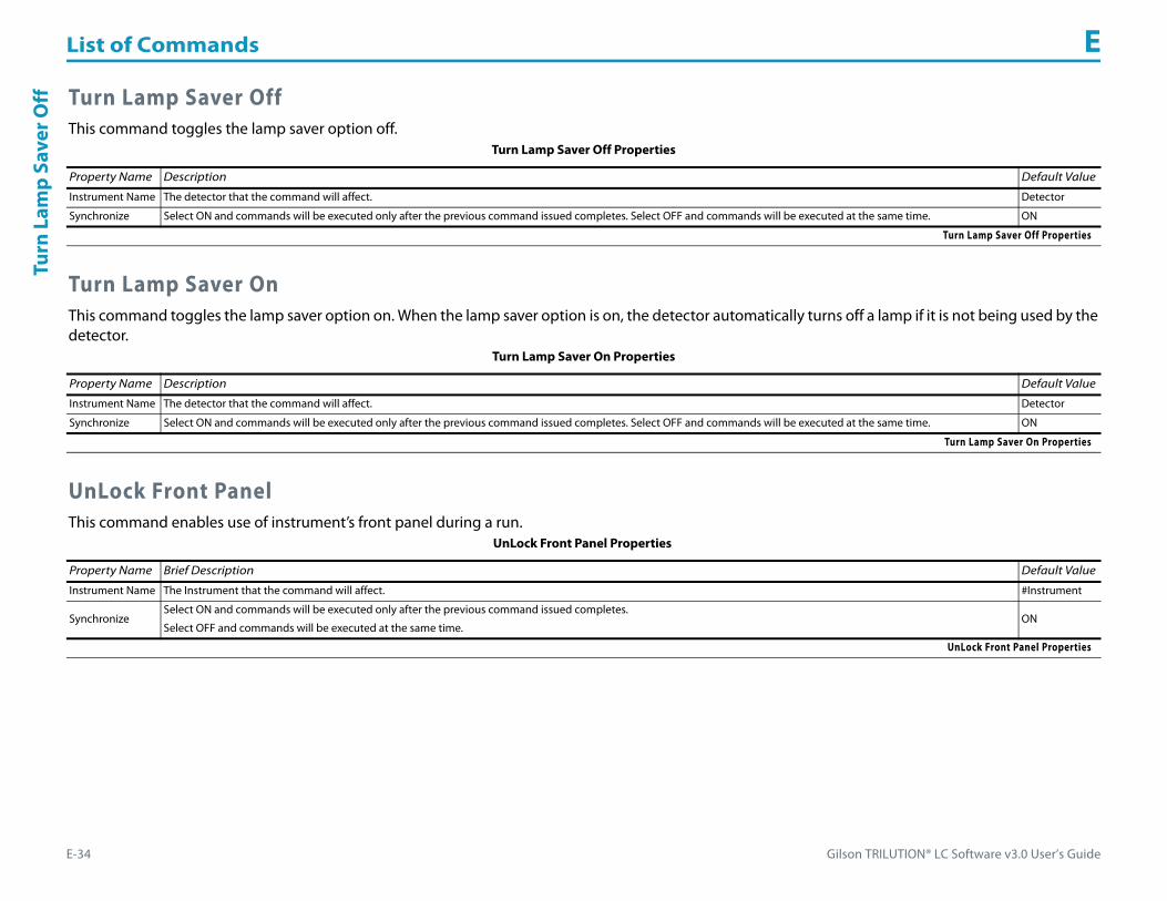
List of Commands E
E-34 Gilson TRILUTION® LC Software v3.0 User’s Guide
Turn
Lam
p Sa
ver O
ff Turn Lamp Saver OffThis command toggles the lamp saver option off.
Turn Lamp Saver OnThis command toggles the lamp saver option on. When the lamp saver option is on, the detector automatically turns off a lamp if it is not being used by the detector.
UnLock Front PanelThis command enables use of instrument’s front panel during a run.
Turn Lamp Saver Off Properties
Property Name Description Default Value
Instrument Name The detector that the command will affect. Detector
Synchronize Select ON and commands will be executed only after the previous command issued completes. Select OFF and commands will be executed at the same time. ON
Turn Lamp Saver Off Properties
Turn Lamp Saver On Properties
Property Name Description Default Value
Instrument Name The detector that the command will affect. Detector
Synchronize Select ON and commands will be executed only after the previous command issued completes. Select OFF and commands will be executed at the same time. ON
Turn Lamp Saver On Properties
UnLock Front Panel Properties
Property Name Brief Description Default Value
Instrument Name The Instrument that the command will affect. #Instrument
SynchronizeSelect ON and commands will be executed only after the previous command issued completes.
Select OFF and commands will be executed at the same time.ON
UnLock Front Panel Properties
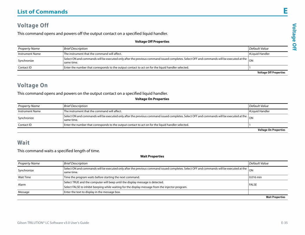
Gilson TRILUTION® LC Software v3.0 User’s Guide E-35
List of Commands EVoltage O
ff
Voltage OffThis command opens and powers off the output contact on a specified liquid handler.
Voltage OnThis command opens and powers on the output contact on a specified liquid handler.
WaitThis command waits a specified length of time.
Voltage Off Properties
Property Name Brief Description Default Value
Instrument Name The instrument that the command will affect. #Liquid Handler
Synchronize Select ON and commands will be executed only after the previous command issued completes. Select OFF and commands will be executed at the same time. ON
Contact ID Enter the number that corresponds to the output contact to act on for the liquid handler selected. 1
Voltage Off Properties
Voltage On Properties
Property Name Brief Description Default Value
Instrument Name The instrument that the command will affect. #Liquid Handler
Synchronize Select ON and commands will be executed only after the previous command issued completes. Select OFF and commands will be executed at the same time. ON
Contact ID Enter the number that corresponds to the output contact to act on for the liquid handler selected. 1
Voltage On Properties
Wait Properties
Property Name Brief Description Default Value
Synchronize Select ON and commands will be executed only after the previous command issued completes. Select OFF and commands will be executed at the same time. ON
Wait Time Time the program waits before starting the next command. 0.016 min
AlarmSelect TRUE and the computer will beep until the display message is detected.
Select FALSE to inhibit beeping while waiting for the display message from the injector program.FALSE
Message Enter the text to display in the message box.
Wait Properties

List of Commands E
E-36 Gilson TRILUTION® LC Software v3.0 User’s Guide
Wai
t for
Cha
nge
in C
onta
ct S
tate Wait for Change in Contact State
This command initiates a wait in the method until a contact state change is detected of the specified input contact on the specified instrument.
Wait for Contact StateThis command initiates a wait in the Method until a specified contact state change is detected of the specified input contact on the specified instrument.
Wait for Change in Contact State Properties
Property Name Brief Description Default Value
Instrument Name The instrument that the command will affect. #Liquid Handler
Synchronize Select ON and commands will be executed only after the previous command issued completes. Select OFF and commands will be executed at the same time.
ON
Contact ID The input contact being queried. Valid range A–E. A
AlarmSelect TRUE and the computer will beep until the display message is detected.
Select FALSE to inhibit beeping while waiting for the display message from the injector program.FALSE
Message Enter the text to display in the message box.
Wait for Change in Contact State Properties
Wait for Change in Contact State Properties
Property Name Brief Description Default Value
Instrument Name The instrument that the command will affect. #Liquid Handler
Synchronize Select ON and commands will be executed only after the previous command issued completes. Select OFF and commands will be executed at the same time. ON
Contact ID The input contact being queried. Valid range A–E. A
AlarmSelect TRUE and the computer will beep until the display message is detected.
Select FALSE to inhibit beeping while waiting for the display message from the injector program.FALSE
Message Enter the text to display in the message box.
State Select ON and the system will wait for the contact to be in a closed state. Select OFF and the system will wait for the contact to be in an open state.
Wait for Change in Contact State Properties

Gilson TRILUTION® LC Software v3.0 User’s Guide E-37
List of Commands EW
ait with D
isplay
Wait with DisplayFor synchronization between injector program and TRILUTION. During the run, TRILUTION enters a wait state until the indicated message appears. When the message appears, TRILUTION continues the run.
Write to DisplayThis command displays a message in the front panel display of the selected instrument.
Zero Analog Offset VoltageThis command sets the selected 506C System Interface channel’s trace to 0 mV.
Wait with Display Properties
Property Name Brief Description Default Value
Instrument Name The Instrument that the command will affect. #Instrument
SynchronizeSelect ON and commands will be executed only after the previous command issued completes.
Select OFF and commands will be executed at the same time.ON
Message Enter the text to wait for.
Line Number For two-line displays, indicates where the message will be displayed. 1
AlarmSelect TRUE and the computer will beep until the display message is detected.
Select FALSE to inhibit beeping while waiting for the display message from the injector program.FALSE
Wait with Display Properties
Write to Display Properties
Property Name Brief Description Default Value
Instrument Name The instrument that the command will affect. #Liquid Handler
SynchronizeSelect ON and commands will be executed only after the previous command issued completes.
Select OFF and commands will be executed at the same time.ON
Message Enter the text to display. Message
Line Number For two-line displays, indicate the line on which to display the message. 1
Write to Display Properties
Zero Analog Offset Voltage Properties
Property Name Description Default Value
Instrument Name The 506C System Interface that the command will affect. Contacts
Zero Analog Offset Voltage Properties (Page 1 of 2)
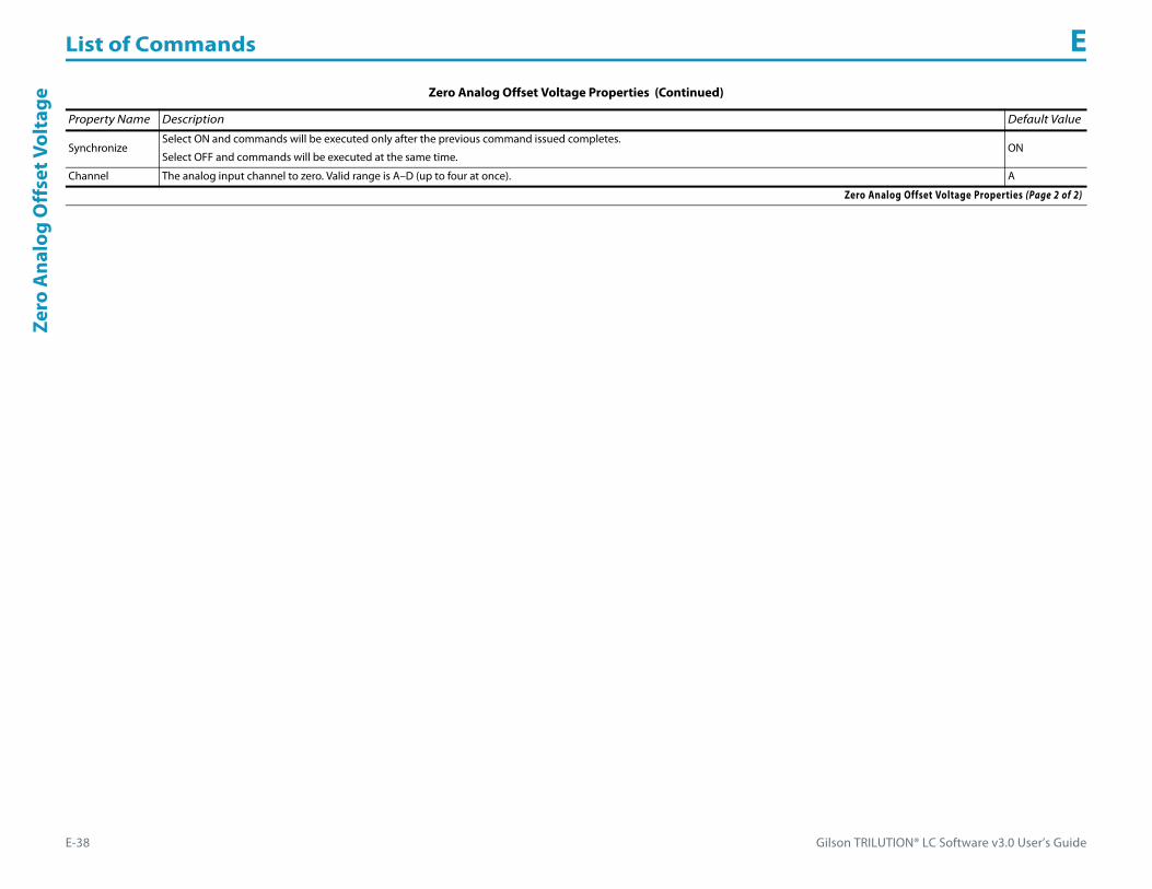
List of Commands E
E-38 Gilson TRILUTION® LC Software v3.0 User’s Guide
Zero
Ana
log
Off
set V
olta
ge
SynchronizeSelect ON and commands will be executed only after the previous command issued completes.
Select OFF and commands will be executed at the same time.ON
Channel The analog input channel to zero. Valid range is A–D (up to four at once). A
Zero Analog Offset Voltage Properties (Continued)
Property Name Description Default Value
Zero Analog Offset Voltage Properties (Page 2 of 2)
Gilson TRILUTION® LC Software v3.0 User’s Guide F-1
Task Builder F
A task is a grouping of simple actions to be performed on instruments in a system. A task is a combination of commands and operators, and it serves as a building block for a method.
Create, modify, delete, export, or import tasks in the Task Builder.
The drag-and-drop feature provides the ability to create tasks easily by dragging the commands, tasks, variables, and operators from the side palette and dropping them into the workspace.
Multiple tasks can be opened at a time.
Access the Task Builder by:
• clicking Task from the Liquid Chromatography menu.
• right-clicking on a control task in a method, and then selecting Open.
This appendix provides information about the following:
• How to Create a Task
• How to Export Tasks
• How to Import Tasks

Task Builder F
F-2 Gilson TRILUTION® LC Software v3.0 User’s Guide
Task
Bui
lder Task Builder Window
The Task Builder is a graphical user interface used to build a task.
The Task Builder window includes:• Tasks Palette• Operators Palette• Commands Palette• Action Buttons• Workspace• Info Window
Use the Task Builder to:• Create new tasks; refer to How to Create a Task.• Modify existing tasks; refer to Modify a Task.• Permanently delete tasks; refer to Delete a Task.• Export tasks; refer to How to Export Tasks.• Import tasks; refer to How to Import Tasks.
Tasks PaletteThe Tasks palette lists the saved (custom) tasks and pre-defined, Gilson-supplied tasks.
For descriptions of Gilson-supplied tasks, refer to Appendix A, List of Tasks.
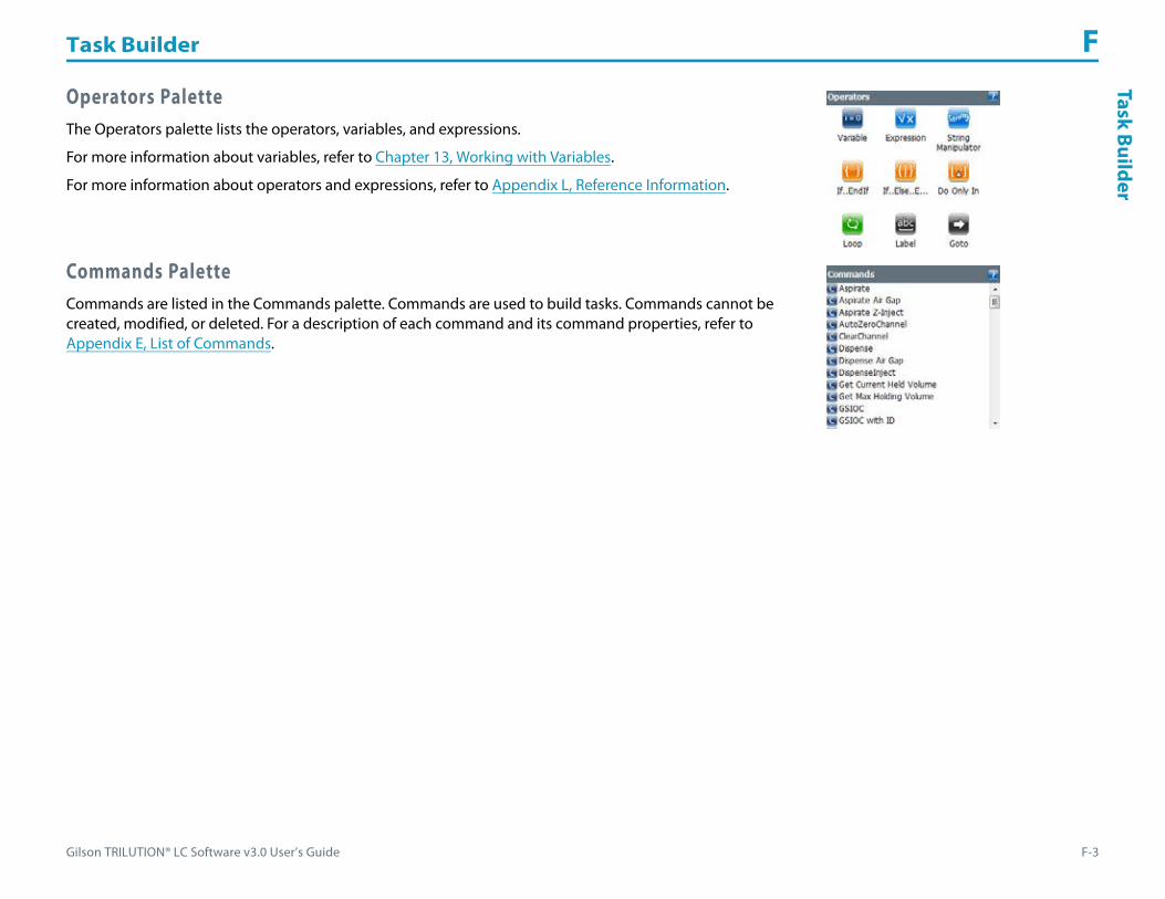
Gilson TRILUTION® LC Software v3.0 User’s Guide F-3
Task Builder FTask Builder
Operators PaletteThe Operators palette lists the operators, variables, and expressions.
For more information about variables, refer to Chapter 13, Working with Variables.
For more information about operators and expressions, refer to Appendix L, Reference Information.
Commands PaletteCommands are listed in the Commands palette. Commands are used to build tasks. Commands cannot be created, modified, or deleted. For a description of each command and its command properties, refer to Appendix E, List of Commands.

Task Builder F
F-4 Gilson TRILUTION® LC Software v3.0 User’s Guide
Task
Bui
lder Action Buttons
The following action buttons are located in the lower left corner of the Task Builder.
WorkspaceThe workspace is used to build new or modify existing tasks.
The left panel provides the sequence. The right panel shows the operator container for the selected operator that can contain commands, tasks, or other operators.
Commands are represented by the following icon: .
Action Button Description
NewCreates a new task.
For more information, refer to How to Create a Task.
OpenOpens an existing task.
For more information, refer to View a Task.
SaveSaves an existing task to the same name.
For more information, refer to Save a Task.
Save As Saves a new task or saves an existing task to a new name. Specify the task type. Optionally, type a short and/or long description for the task.
Modify Allows for modifying the short and/or long description and/or task type for the task or selecting a custom icon.
DeleteDeletes the open task or all versions of the task.
For more information, refer to Delete a Task.
ExportExports the task to a specified location as a .LCTE file.
For more information, refer to How to Export Tasks.
Refresh Reloads the Tasks palette with any new tasks created.
ImportImports a .LCTE file, lists the task in the Tasks palette, and replaces it in the method.
For more information, refer to How to Import Tasks.
Close Closes the open task while leaving the Task Builder open.
Close All Closes all open tasks while leaving the Task Builder open.

Gilson TRILUTION® LC Software v3.0 User’s Guide F-5
Task Builder FTask Builder
ToolbarClick an icon to perform the action described below.
Right-click Menu
Command
Right-click on a command icon in the workspace to display the following menu options:
Icon Label Description
Undo Reverses the last action when the last action was to add or delete a task, command, or operator.
Redo Repeats the last action prior to an undo.
Variable List Lists the available variables for the task. Click to view the list of variables used in the task. For more information about variables, refer to Chapter 13, Working with Variables .
Back Provides the ability to step through nested commands, tasks, and operators in Normal view.
Help Displays the on-line help information.
Menu Description
Cut Cuts the command for deleting or pasting in a new location in the workspace, in an operator or expression, or in another task.
Copy Copies the command to duplicate in a new location in the workspace, in an operator or expression, or in another task.
Paste Places a cut or copied command in the workspace, in an operator or expression, or in another task.
Delete Removes the command from the workspace.
Line Break A toggle for moving the selected element after the selected element to the next line below the selected element.
Properties Opens the command property page for the selected command.

Task Builder F
F-6 Gilson TRILUTION® LC Software v3.0 User’s Guide
Task
Bui
lder Task
Right-click on a task icon to display the following menu options:
Workspace
Right-click in the workspace to display the following menu options:
Info WindowThe info window lists information about the open task (if applicable) and the name of the current user.
Menu Description
Cut Cuts the task for deleting or pasting in a new location in the workspace, in an operator or expression, or in another task..
Copy Copies the task to duplicate in a new location in the workspace, in an operator or expression, or in another task.
Paste Places a cut or copied task in the workspace, in an operator or expression, or in another task.
Delete Removes the task from the workspace.
Line Break A toggle for moving task after the selected task to the next line below the selected task.
Properties Opens the task property page for the selected task.
Open Task Opens the task to show the commands and expressions that constitute the task.
Menu Description
Paste Places a cut or copied command or task in the workspace, in an operator or expression, or in another task.
View Extended Hides the right panel and expands the operator containers within the sequence in the workspace to show the tasks, commands, or operators contained within.
View Normal Collapses the operator container in the right panel for the tasks, commands, and operators contained within the selected operator.
Gilson TRILUTION® LC Software v3.0 User’s Guide F-7
Task Builder FTask Builder
How to Create a TaskDo one or all of the following one or many times:• From the Commands palette, drag a command and then drop it in the workspace. The command property page for that command
appears.Review the values for each command property and modify, if necessary.For descriptions of the commands, refer to Appendix E, List of Commands.
• From the Tasks palette, drag a task and then drop it in the workspace. The task property page for that task appears.Review the values for each task property and modify, if necessary.For descriptions of the tasks, refer to Appendix A, List of Tasks.
• From the Operators palette, drag an expression, variable, or operator and then drop it in the workspace.For more information about variables, refer to Chapter 13, Working with Variables.
Optionally, obtain and use the Property Page Creator to create a task property page for the custom task.

Task Builder F
F-8 Gilson TRILUTION® LC Software v3.0 User’s Guide
Task
Bui
lder View a Task
In the Task Builder, do one of the following:• On the Tasks palette, do one of the following:
• Double-click a task.• Right-click on a task and then on the submenu displayed, click Open.
• Click Open to display the Open Task window.a) Optionally, clear the Show Latest Version check box to see all versions of all tasks that
have been created on the computer and have not been deleted.b) Select the task to open.c) Click OK to display the task in the workspace.
Modify a TaskModify a Task by doing any of the following:• Adding tasks, commands, or operators to the workspace.• Deleting tasks, commands, or operators from the workspace.
Tasks, commands, and operators can be deleted from the workspace by pressing the DELETE key.• Modifying the properties of the tasks, commands, or operators in the workspace.• Changing the description or custom icon after clicking Modify.
Multiple tasks can be open in the same builder. Individual tabs appear at the top of the window for each open task. Click on the tab to view the task in the workspace.

Gilson TRILUTION® LC Software v3.0 User’s Guide F-9
Task Builder FTask Builder
Save a Task1 Click Save to display the Save Task window.2 On the Save Task window:
a) In the Name field, type a task name.b) In the Description field (optional), type a description for the task.c) Next to the Custom Icon field, click the browse button and then select an icon for the
task (optional). The icon can be of file type Icon (.ICO), Bitmap (.BMP), or JPEG (.JPG), GIF (.GIF), or Portable Network Group (.PNG).
d) In the Task Type field, check the appropriate box or boxes to indicate the filtering for this task.
e) Click OK.
The task is saved and listed in the Tasks palette.

Task Builder F
F-10 Gilson TRILUTION® LC Software v3.0 User’s Guide
Task
Bui
lder How to Export Tasks
1 In the Task Builder, click Export to display the Export window.2 In the Export window:
a) In the Select the items to be exported field, select the tasks.b) In the Select a path field, do either of the following:
• Accept the default path of C:\Documents and Settings\OS User Name\My Documents\TRILUTION LC x.x\Export.1) Click to display the Browse For folder window. On the Browse For folder window, select a folder and then click OK.
3 Click OK. On completion of the export operation, the task is saved in the specified folder with a .LCTE extension.
4 When the export success/fail dialog appears:• Click Details to view the log information of the export operation.• Click OK.
If a task with the same name is found in the export path, an option is provided to rename or overwrite the task or to skip the export operation for that task.

Gilson TRILUTION® LC Software v3.0 User’s Guide F-11
Task Builder FTask Builder
How to Import Tasks1 In the Task Builder, click Import. The Select Task Exported Files window appears.2 in the Select Task Exported Files window:
a) Browse for and select the Task Exported files (.LCTE).b) Click Open.If a custom task with the same name already exists on the system, a dialog appears with options to import the custom task or all custom tasks as a new version (overwrite) rename the custom task, or skip the import operation for that custom task or all custom tasks.
3 When the import success/fail dialog appears:• Click Details to view the log information of the import operation.• Click OK.
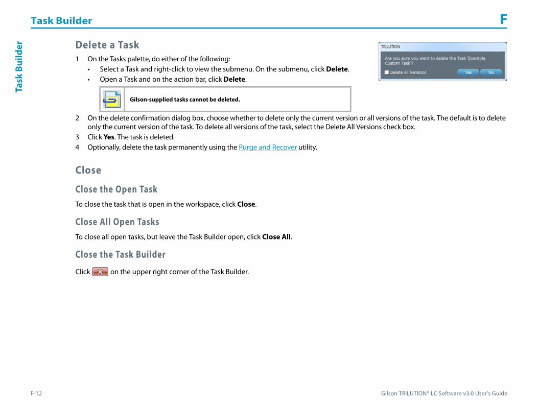
Task Builder F
F-12 Gilson TRILUTION® LC Software v3.0 User’s Guide
Task
Bui
lder Delete a Task
1 On the Tasks palette, do either of the following:• Select a Task and right-click to view the submenu. On the submenu, click Delete.• Open a Task and on the action bar, click Delete.
2 On the delete confirmation dialog box, choose whether to delete only the current version or all versions of the task. The default is to delete only the current version of the task. To delete all versions of the task, select the Delete All Versions check box.
3 Click Yes. The task is deleted. 4 Optionally, delete the task permanently using the Purge and Recover utility.
Close
Close the Open TaskTo close the task that is open in the workspace, click Close.
Close All Open TasksTo close all open tasks, but leave the Task Builder open, click Close All.
Close the Task Builder
Click on the upper right corner of the Task Builder.
Gilson-supplied tasks cannot be deleted.
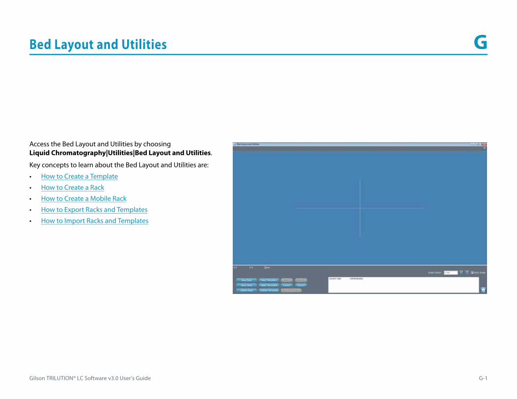
Gilson TRILUTION® LC Software v3.0 User’s Guide G-1
Bed Layout and Utilities G
Access the Bed Layout and Utilities by choosing Liquid Chromatography|Utilities|Bed Layout and Utilities.
Key concepts to learn about the Bed Layout and Utilities are:
• How to Create a Template
• How to Create a Rack
• How to Create a Mobile Rack
• How to Export Racks and Templates
• How to Import Racks and Templates

Bed Layout and Utilities G
G-2 Gilson TRILUTION® LC Software v3.0 User’s Guide
Bed
Layo
ut a
nd U
tilit
ies Custom Templates
TRILUTION allows for using pre-defined templates or creating a custom template with footprints. When creating a custom template, the software requires information about the physical dimensions of the template and the location of the origin (where 0,0,0 is).
Keywords:• Template: The bottom, required layer of a bed layout. Only footprints can be added to templates. For more information, refer to How to
Create a Template.• Origin: Defined by the user, the location of the coordinates X=0, Y=0, Z=0. For more information, refer to Origin on page L-9.• Footprint: A placeholder or area that accepts racks. For more information, refer to Add Existing Rack Footprints to Template or Create a
Rack Footprint.• Rack: A rack requires a footprint before it can be added to a template. Examples of racks are racks, rinse stations, injection port bars, tip
boxes, and microplates. For more information, refer to How to Create a Rack or How to Create a Mobile Rack.
How to Create a Template1 Click New Template. The New Template window appears.2 In the New Template window, enter the template dimensions and
location (Origin).3 Select one or more compatible instruments by checking the box or
boxes.4 Click OK.5 Add, or create and then add, rack footprints to the template. For
more information, refer to Add Existing Rack Footprints to Template or Create a Rack Footprint.
6 Click Save As. The Save As Template window appears.7 Enter the template name, short description, and long description in
the Save As Template window.8 Click OK.

Gilson TRILUTION® LC Software v3.0 User’s Guide G-3
Bed Layout and Utilities GBed Layout and U
tilities
Add Existing Rack Footprints to TemplateA rack footprint is an area that accepts racks. Use Gilson-supplied rack footprints or create custom rack footprints.
Add a Single Rack FootprintTo add a single rack footprint to a template:
1 Click on the template. It highlights in red.2 Do either of the following:
• Click Add Elements.• Right-click and then select Add Elements....The Template Elements dialog appears.
3 Select a Rack Footprint.4 Enter the X, Y, and Z Relative positions.
The position is calculated with respect to the origin. For more information, refer to Origin on page L-9.When X = 0 and Y= 0, the center of the footprint is positioned over the origin.When Z = 0, the bottom of the footprint is placed at the same level as the top of the template.
5 Optionally, select a value from the Rotation drop-down. The default is 0°. (Rotation values: 90°, 180°, and 270°)6 Click Update Preview. Make modifications, if necessary. Click Reset to clear the footprint from the preview, if necessary.7 Click Add.8 Click Close to return to the template.

Bed Layout and Utilities G
G-4 Gilson TRILUTION® LC Software v3.0 User’s Guide
Bed
Layo
ut a
nd U
tilit
ies Add Multiple Rack Footprints
To add an array of identical rack footprints to a template:
1 Click on the template. It highlights in red.2 Do either of the following:
• Click Add Elements.• Right-click, and then select Add Elements....The Template Elements dialog appears.
3 Select the Rack Footprint to add as an array.4 Select the Multiple check box to enable the necessary fields.5 Enter the X, Y, and Z Relative positions for the center of the element in column 1, row 1.
The position is calculated with respect to the origin. For more information, refer to Origin on page L-9.When X = 0 and Y= 0, the footprint in column 1, row 1 is centered over the center of the origin.
6 Specify the number of columns and the number of rows.7 Specify the distance between footprints within a column (X Offset) and the distance between wells within a row (Y Offset).8 Optionally, select a value from the Rotation drop-down. The default is 0°. (Rotation values: 90°, 180°, and 270°)9 Click Update Preview. Make modifications, if necessary. Click Reset to clear the footprints from the preview, if necessary.10 Click Add.11 Click Close to return to the template.
Create a Rack Footprint1 Click on the rack or template. It highlights in red.2 Do either of the following:
• Click Add Elements.• Right-click, and then select Add Elements....
3 Click Rack Footprint, and then click New.4 Enter a Footprint Name for the rack footprint.5 Select the Shape: Rectangle or Circle.
a) For a rectangle, enter the Length and Width.b) For a circle, enter the Diameter.
6 Click OK.
To add the new rack footprint to a template, refer to Add Existing Rack Footprints to Template, or to add it to a rack, refer to Add Existing Rack Elements to Rack.
Gilson TRILUTION® LC Software v3.0 User’s Guide G-5
Bed Layout and Utilities GBed Layout and U
tilities
Modify a Rack or TemplateTo make changes to the properties of a rack or template:
1 Select the rack or template.2 Right-click, and then select Properties.3 Make desired changes to the properties, and then click OK.4 Save the rack or template.
Delete a Rack or TemplateGilson-supplied racks and templates cannot be deleted.
To delete user-created custom racks or templates:
1 Click Delete Template to delete a template or Delete Rack to delete a rack. The Delete Rack or Delete Template window appears.2 Select the rack or template to be deleted and then click Delete. All versions of the rack or template are deleted.
To delete a specific version, select Show Versions, select the version to delete, and then click Delete.3 Optionally, delete the rack or template permanently using the Purge and Recover utility.

Bed Layout and Utilities G
G-6 Gilson TRILUTION® LC Software v3.0 User’s Guide
Bed
Layo
ut a
nd U
tilit
ies Custom Racks
Create a rack by specifying the dimensions for the rack and the wells or elements to be used on the rack. Either create custom wells or elements or use the pre-defined wells and elements provided by Gilson. Wells and elements can be added individually or as an array.
Information stored concerning the rack includes its physical dimensions, the type of wells that it holds and their location, and the templates on which the rack can be placed.
To view the properties of an element, select it, right-click, and then select Properties....
Keywords:• Rack: A rack requires a footprint before it can be added to a template. Examples of racks are racks, rinse stations, injection port bars,
tip boxes, and microplates. For more information, refer to How to Create a Rack or How to Create a Mobile Rack.• Rack Element: Rack elements include rack footprints, wells, tips, handles, or mobile well footprints. For more information, refer to Add
Existing Rack Elements to Rack or Create a Rack Element.• Rack Footprint: Area that accepts racks. For more information, refer to Create a Rack Footprint.• Well: Wells can only go in racks. For more information, refer to Create a Well.• Target: A position defined within a well. Zones can be assigned to a target. For more information, refer to Create a Target in a Well.• Template: The template is the bottom, required layer of a bed layout. Only footprints can be added to templates. For more information,
refer to How to Create a Template.• Handle: A position designated in a rack, which makes the rack mobile. A handle cannot be created, but existing handles can be added to
a rack. For more information, refer to Add Existing Rack Elements to Rack.• Collect Handle: Target to which the probe is sent to move the DEC rack to the Collect position. For more information about how to add
a Collect Handle to a rack, refer to Add Existing Rack Elements to Rack.• Drain Handle: Target to which the probe is sent to move the DEC rack to the Drain position. For more information about how to add a
Drain Handle to a rack, refer to Add Existing Rack Elements to Rack.• Initial Handle: Target to which the probe is sent during rack initialization. The Initial Handle position should be as close as possible to the
Collect or Drain Handle positions (recommend 1.5 mm). Too large of a distance between the Initial Handle and the Drain or Collect Handle may result in the probe missing Drain or Collect Target after initialization of the rack. For more information about how to add an Initial Handle to a rack, refer to Add Existing Rack Elements to Rack
• Mobile Well Footprint: Area that accepts mobile wells. For more information on how to use this feature, contact [email protected].

Gilson TRILUTION® LC Software v3.0 User’s Guide G-7
Bed Layout and Utilities GBed Layout and U
tilities
How to Create a Rack1 Click New Rack. The New Rack dialog appears.2 In the New Rack window, set the rack shape: Rectangle or Circle.3 Enter the dimensions.
a) For a rectangular rack, define Length (X), Width (Y), and the height.b) For a circular rack, define the diameter and the height. The rack height is measured with respect to the point of contact between the rack and its holder.For a rack placed on a template, ‘Height’ is measured with respect to the rack bottom.For a rack placed on antlers, ‘Height’ is measured with respect to the underside of the rack tabs. A height of “0” means that the top of the rack is level with the plane of the support.This reference is important, when a footprint or well is added to a custom rack, the height Z is calculated with respect to this plane. In addition, the probe height in a custom rack is calculated with respect to this plane.Be very careful when designing a custom rack that can be placed on antlers and on a tray, as the probe height in tasks will be calculated with respect to this coordinate.
4 Enter the coordinates for the rack Origin. The default is 0,0,0, which is the center of the rack.5 Select one or more footprints where the rack can be placed.6 Click OK.7 Add, or create and then add, rack elements to the rack. For more information, refer to Add Existing Rack Elements to Rack or Create a Rack
Element.8 Click Save As. The Save As Rack window appears.9 Enter the rack name, short description, and long description in the Save As Rack window.10 Click OK.
Bed Layout and Utilities G
G-8 Gilson TRILUTION® LC Software v3.0 User’s Guide
Bed
Layo
ut a
nd U
tilit
ies How to Create a Mobile Rack
A Mobile Rack is made up of three separate racks: a Holder rack, the DEC rack (“slider” rack), and the Collect rack.
The Holder Rack has three parts: • Collect Footprint• DEC Footprint• Sink (Drain well)
The DEC (“Slider”) Rack has four parts: • Initial Handle – Probe position when initializing the mobile rack.• Drain Handle – Probe position when moving the mobile rack to Drain.• Collect Handle – Probe position when moving the mobile rack to Collect.• DEC wells (DEC Cartridges)
The Collect Rack has one part:• Collect wells (tubes)
Holder Rack1 Create the rack. For more information, refer to How to Create a Rack.2 Create and Add Collect Footprint and DEC Footprint
a) Follow the instructions for Create a Rack Footprint twice: once for the Collect Footprint and once for the DEC Footprint.3 Create and Add Sink (Drain Well).
a) Follow the instructions for Create a Well. Be sure to select Drain for the Well Type.4 Save the rack.

Gilson TRILUTION® LC Software v3.0 User’s Guide G-9
Bed Layout and Utilities GBed Layout and U
tilities
DEC (“Slider”) Rack1 Create the rack. For more information, refer to How to Create a Rack.2 Add Handles
a) Follow the instructions for Add Existing Rack Elements to Rack three times: once to add the Initial Handle, once to add the Drain Handle, and once to add the Collect Handle.
3 Add DEC Wells (DEC Cartridges).a) Follow the instructions for Add Existing Rack Elements to Rack. Gilson supplies three DEC options, which are filtered under the rack
element type Well: DEC 1mL, DEC 3 mL, and DEC 6 mL.4 Set Mobile Rack Settings.
a) Click Mobile Rack Settings. The Mobile Rack Settings dialog appears.b) Click New.c) Select the DEC Footprint that was created for the Holder Rack.d) Indicate the Drain Y and Collect Y positions.
Drain = 0 minus ½ the width of the DEC Footprint plus ½ the width of the DEC RackCollect = ½ the width of the DEC Footprint minus ½ the width of the DEC RackThe preview will show the mobile rack positions overlaid. The Collect position is green. The Drain position is red.
5 Save the rack.
Collect Rack1 Create the rack. For more information, refer to How to Create a Rack.2 Add Wells.
a) Follow the instructions for Add Existing Rack Elements to Rack to add the collection vessels to the rack, which are filtered under the rack element type Well.
3 Save the rack.

Bed Layout and Utilities G
G-10 Gilson TRILUTION® LC Software v3.0 User’s Guide
Bed
Layo
ut a
nd U
tilit
ies Add Existing Rack Elements to Rack
Rack elements include rack footprints, wells, tips, handles, or mobile well footprints.
Using the Rack Elements dialog, add a single rack element or an array of rack elements to the rack.
Add a Single Rack ElementTo add a single rack element to a rack:
1 Click on the rack. It highlights in red.2 Do either of the following:
• Click Add Elements.• Right-click, and then select Add Elements....
3 Select an element: Rack Footprint, Well*, Tip*, Handle, or Mobile Well Footprint.4 Enter the X, Y, and Z Relative positions.
The position is calculated with respect to the origin.When X = 0 and Y = 0, the center of the element is positioned over the origin.When Z = 0, the bottom of the element is placed at the same level as the top of the rack: level with the point of contact between the rack and its holder (tray or antler).*When adding a well or tip, additional Z options are available. Choose to Measure Z to well/Tip Bottom or Measure Z to Well/Tip Top.
5 Optionally, select a value from the Rotation drop-down. Default is 0°. (Rotation values: 90°, 180°, and 270°)6 Click Update Preview. Make modifications, if necessary. Click Reset to clear the element from the preview, if necessary.7 Click Add.8 Click Close to return to the rack.
Gilson TRILUTION® LC Software v3.0 User’s Guide G-11
Bed Layout and Utilities GBed Layout and U
tilities
Add Multiple Rack ElementsTo add an array of identical rack elements to a template:
1 Click on the rack. It highlights in red.2 Do either of the following:
• Click Add Elements.• Right-click, and then select Add Elements....
3 Select the element that you want to add as an array: Rack Footprint, Well*, Tip*, Handle, or Mobile Well Footprint.4 Select the Multiple check box to enable the necessary fields.5 Enter the X, Y, and Z Relative positions for the center of the element in column 1, row 1.
The position is calculated with respect to the rack center.When X = 0 and Y= 0, the element in column 1, row 1 is centered over the origin.When Z = 0, the bottom of the element is placed at the same level as the top of the rack: level with the point of contact between the rack and its holder (tray or antler).*When adding a well or tip, additional Z options are available. Choose to Measure Z to Well/Tip Bottom or Measure Z to Well/Tip Top.
6 Specify the number of columns and the number of rows.7 Specify the distance between wells within a column (X Offset) and the distance between wells within a row (Y Offset).8 Optionally, select a value from the Rotation drop-down. Default is 0°. (Rotation values: 90°, 180°, and 270°)9 Click Update Preview. Make modifications, if necessary. Click Reset to clear the elements from the preview, if necessary.10 Click Add.11 Click Close to return to the rack.

Bed Layout and Utilities G
G-12 Gilson TRILUTION® LC Software v3.0 User’s Guide
Bed
Layo
ut a
nd U
tilit
ies Create a Rack Element
Rack elements include rack footprints, wells, tips, handles, or mobile well footprints. TRILUTION allows for using the pre-defined elements provided by Gilson or for creating custom elements for use with non-standard equipment.
For more information about creating a rack element, refer to:• Create a Rack Footprint• Create a Well• Create a Tip• Create a Mobile Well Footprint
Modify a Rack or TemplateTo make changes to the properties of a rack or template:
1 Select the rack or template.2 Right-click, and then select Properties.3 Make desired changes to the properties, and then click OK.4 Save the rack or template.
Delete a Rack or TemplateGilson-supplied racks and templates cannot be deleted.
To delete user-created custom racks or templates:
1 Click Delete Template to delete a template or Delete Rack to delete a rack. The Delete Rack or Delete Template window appears.2 Select the rack or template to be deleted and then click Delete. All versions of the rack or template are deleted.
To delete a specific version, select Show Versions, select the version to delete, and then click Delete.3 Optionally, delete the rack or template permanently using the Purge and Recover utility.

Gilson TRILUTION® LC Software v3.0 User’s Guide G-13
Bed Layout and Utilities GBed Layout and U
tilities
Create a Rack ElementRack elements include rack footprints, wells, tips, handles, or mobile well footprints. TRILUTION allows for using the pre-defined elements provided by Gilson or for creating custom elements for use with non-standard equipment.
For more information about creating a rack element, refer to:• Create a Rack Footprint• Create a Well• Create a Tip• Create a Mobile Well Footprint
Create a Well1 Click on the rack. It highlights in red.2 Do either of the following:
• Click Add Elements.• Right-click, and then select Add Elements....
3 Click Well and then click New.4 Enter a Well Name for the well.5 Select a Well Type from the drop-down list.6 Select the Shape: Rectangle or Circle.
a) For a circular well, enter the Diameter, Height, and Maximum Volume for the well.b) For a rectangular well, enter the Length, Width, Height, and Maximum Volume for the
well.7 If the well is to be a mobile well, select the mobile well footprints with which the well should be associated. For more information about
creating mobile well footprints, refer to Create a Mobile Well Footprint.8 Click OK.
For information about adding a target within a well, refer to Create a Target in a Well.

Bed Layout and Utilities G
G-14 Gilson TRILUTION® LC Software v3.0 User’s Guide
Bed
Layo
ut a
nd U
tilit
ies Create a Target in a Well
1 Right-click on a rack and then select Add Elements....2 Click Well, select the well to which the target(s) will be added, and then click Edit.3 Click New.4 Enter a Target Name for the target.5 Select a Target Type.6 Enter the X, Y, and Z Relative positions for the target. The position is calculated with respect to the
center of the well.7 Repeat steps 3–6 for each additional target to be added.8 Click OK to exit the Edit Well dialog.
Create a Tip1 Click on the rack, it highlights in red.2 Do either of the following:
• Click Add Elements.• Right-click, and then select Add Elements....
3 Click Tip and then click New.4 Enter a Tip Name for the Tip.5 For the Shape, select Circle.6 For the Diameter, enter the maximum inside diameter of the tip.7 For the Height, enter the total length of the tip (Top– Bottom = Height).8 For the Effective Height, enter the length from the bottom of the tip holder to the bottom of the tip when the
tip is installed. 9 For the Maximum Volume, enter the maximum amount of liquid that can be aspirated into the tip. 10 Select the Tip Crush Z target, right-click, and then select Edit.
Tip Crush Z is used to install the tips by moving the tip holder down in "spongy" mode. The Tip Crush Z is generally greater than the actual distance need to install the tip. The greater the distance traveled, the greater the force used to install the tip.
11 For Z Relative, enter the distance from the tip top (less Target Z Delta) while the tip holder is "spongy" to crush the tip onto the tip holder, and then click OK to return to the New Tip dialog.

Gilson TRILUTION® LC Software v3.0 User’s Guide G-15
Bed Layout and Utilities GBed Layout and U
tilities
12 Select the Tip Flight Z target, right-click, and then select Edit.Tip Flight Z is used to set a height that will allow the bottom of the tip to clear all of the racks, while preventing the tip from being removed when the Move Z Top command is used. While the tip is installed, the Move Z Top command will move to the Z Safe Height – Tip Flight Z. Ejecting the tip will reset the height to the Z Safe Height.
13 For Z Relative, enter the height from the top (less Z Safe Height) at which the bottom of the tip travels after the tips are installed, and then click OK to return to the New Tip dialog.
14 Select the Tip Target Z Delta target, right-click, and then select Edit.Tip Target Z Delta is used to seat the tip holder into the tip before doing the Crush Z and is also the height to move to after doing the Crush Z and before moving to the top.
15 For Z Relative, enter the distance traveled from the tip top, and then click OK to return to the New Tip dialog.16 Click OK in the New Tip dialog.
Create a Mobile Well Footprint1 Click on the rack, it highlights in red.2 Do either of the following:
• Click Add Elements.• Right-click, and then select Add Elements....
3 Click Mobile Well Footprint and then click New.4 Enter a Footprint Name for the mobile well footprint.5 Select the Shape: Rectangle or Circle.
a) For a rectangle, enter the Length and Width.b) For a circle, enter the Diameter.
6 Click OK.
For more information on how to use this feature, contact [email protected].
Multiple tip types can be created for the same rack tip box, as long as the tip height and diameter are the same. Modify the Tip Target Z Delta, Tip Crush Z, and Tip Flight Z to install the tips differently without creating a new rack.

Bed Layout and Utilities G
G-16 Gilson TRILUTION® LC Software v3.0 User’s Guide
Bed
Layo
ut a
nd U
tilit
ies Modify a Rack Element
A Gilson-supplied rack element can be modified, but must be given a new name. Modifying a Gilson-supplied rack element can be a simple way to create a new rack element.
To modify a rack element:
1 Do either of the following:• Click Add Elements.• Right-click, and then select Add Elements....
2 Click on the type of element to modify: Rack Footprint, Well, Tip, or Mobile Well Footprint.
3 Select the element to modify. The Edit button becomes active.4 Click Edit.5 Make desired changes to the properties and then click OK.
The properties are updated for future use of the rack element. Racks that use that rack element are NOT updated to use the new rack element properties.
Modify a Target1 Do either of the following:
• Click Add Elements.• Right-click, and then select Add Elements....
2 Click Well, select the well that contains the target, and then click Edit. The Edit Well dialog is displayed.
3 Select the target and then click Edit.4 Modify the Target Name for the target, if desired.5 Modify the relative X, Y, and Z positions for the target, if desired. The position is calculated
with respect to the center of the well.6 Click OK to exit the Target Properties dialog.

Gilson TRILUTION® LC Software v3.0 User’s Guide G-17
Bed Layout and Utilities GBed Layout and U
tilities
Delete a Rack ElementGilson-supplied rack elements cannot be deleted.
To delete a user-created custom rack element:
1 Do either of the following:• Click Add Elements.• Right-click, and then select Add Elements....
2 Click on the type of element to delete: a custom Rack Footprint, Well, Tip, or Mobile Well Footprint.3 Select the element to delete.4 Click Delete.
Delete Element from Rack or Rack Footprint from TemplateTo delete a rack element from a rack or a rack footprint from a template, select the element or rack footprint, and then do either of the following:• Right-click and then select Delete.• Press the DELETE key.
Delete a Target1 Do either of the following:
• Click Add Elements.• Right-click, and then select Add Elements....
2 Click Well, select the Well that contains the target, and then click Edit. The Edit Well dialog is displayed.3 Select the target and then click Delete.4 Click OK to exit the Edit Well dialog.

Bed Layout and Utilities G
G-18 Gilson TRILUTION® LC Software v3.0 User’s Guide
Bed
Layo
ut a
nd U
tilit
ies How to Export Racks and Templates
1 Click Export.2 Select the Rack List or Template List option button.3 Select a rack or template.4 Click the browse icon. The Browse For Folder window is displayed.5 On the Browse For Folder window, select a folder to which the rack or template will be exported, and then click OK.6 Click OK. On completion of the export operation, the rack or template is saved in the specified folder with a .LHR (Rack) or .LHT (Template)
extension.7 When the export success/fail dialog appears:
• Click Details to view the log information of the export operation.• Click OK.
How to Import Racks and Templates1 Click Import. The Import window appears.2 From the Import window:
a) Browse for and select the Rack or Template Exported Files.b) Click Open.
3 When the import success/fail dialog appears:• Click Details to view the log information of the import operation.• Click OK.

Gilson TRILUTION® LC Software v3.0 User’s Guide G-19
Bed Layout and Utilities GBed Layout and U
tilities
Close Bed Layout and UtilitiesDo either of the following:
• Click in the lower right corner to return to the main menu.
• Click in the upper right corner to close the utility.
Gilson TRILUTION® LC Software v3.0 User’s Guide H-1
Open Access H
Users log on to the TRILUTION LC Open Access, choose the application to run from a pick-list, and then use a simple “wizard”, which directs them through the experiment. The intuitive nature of the “wizard” ensures Users will have a quick learning curve. For more information, refer to Open Access Wizard.
TRILUTION LC’s multi-tiered approach allows users of all levels, from novice to expert, access to one of the leading chromatographic software packages in the industry. Several laboratories can benefit from a single Administrator’s expertise.
This appendix provides information about:
• How to Enable Open Access for Applications
• How to Start Open Access
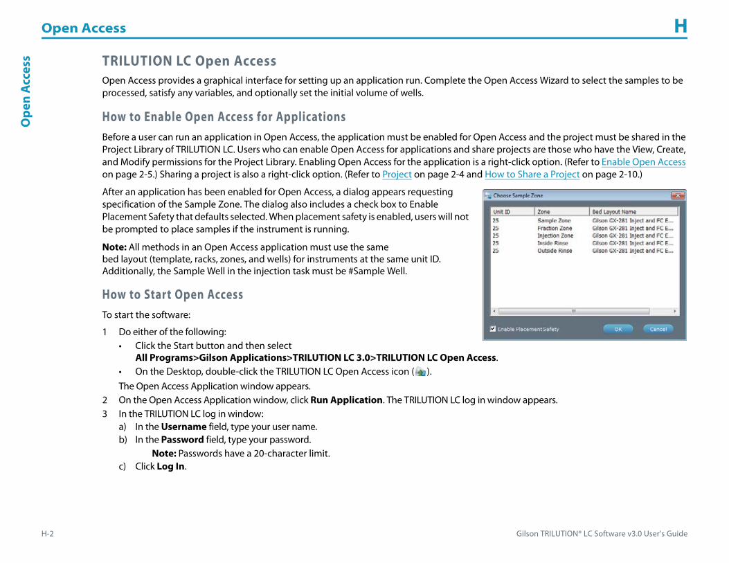
Open Access H
H-2 Gilson TRILUTION® LC Software v3.0 User’s Guide
Ope
nA
cces
s TRILUTION LC Open AccessOpen Access provides a graphical interface for setting up an application run. Complete the Open Access Wizard to select the samples to be processed, satisfy any variables, and optionally set the initial volume of wells.
How to Enable Open Access for ApplicationsBefore a user can run an application in Open Access, the application must be enabled for Open Access and the project must be shared in the Project Library of TRILUTION LC. Users who can enable Open Access for applications and share projects are those who have the View, Create, and Modify permissions for the Project Library. Enabling Open Access for the application is a right-click option. (Refer to Enable Open Access on page 2-5.) Sharing a project is also a right-click option. (Refer to Project on page 2-4 and How to Share a Project on page 2-10.)
After an application has been enabled for Open Access, a dialog appears requesting specification of the Sample Zone. The dialog also includes a check box to Enable Placement Safety that defaults selected. When placement safety is enabled, users will not be prompted to place samples if the instrument is running.
Note: All methods in an Open Access application must use the same bed layout (template, racks, zones, and wells) for instruments at the same unit ID. Additionally, the Sample Well in the injection task must be #Sample Well.
How to Start Open AccessTo start the software:
1 Do either of the following:• Click the Start button and then select
All Programs>Gilson Applications>TRILUTION LC 3.0>TRILUTION LC Open Access.• On the Desktop, double-click the TRILUTION LC Open Access icon ( ). The Open Access Application window appears.
2 On the Open Access Application window, click Run Application. The TRILUTION LC log in window appears.3 In the TRILUTION LC log in window:
a) In the Username field, type your user name.b) In the Password field, type your password.
Note: Passwords have a 20-character limit.c) Click Log In.
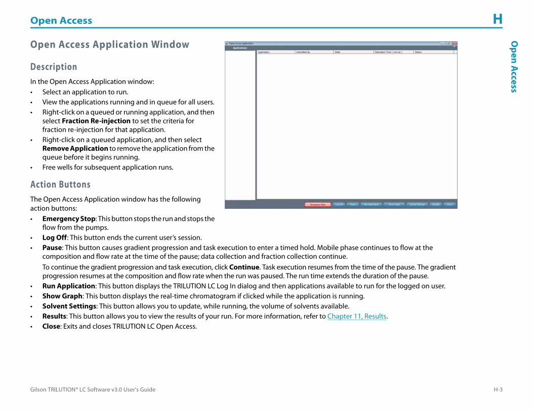
Gilson TRILUTION® LC Software v3.0 User’s Guide H-3
Open Access HO
penA
ccess
Open Access Application Window
DescriptionIn the Open Access Application window:• Select an application to run.• View the applications running and in queue for all users.• Right-click on a queued or running application, and then
select Fraction Re-injection to set the criteria for fraction re-injection for that application.
• Right-click on a queued application, and then select Remove Application to remove the application from the queue before it begins running.
• Free wells for subsequent application runs.
Action ButtonsThe Open Access Application window has the following action buttons:• Emergency Stop: This button stops the run and stops the
flow from the pumps.• Log Off: This button ends the current user’s session.• Pause: This button causes gradient progression and task execution to enter a timed hold. Mobile phase continues to flow at the
composition and flow rate at the time of the pause; data collection and fraction collection continue.To continue the gradient progression and task execution, click Continue. Task execution resumes from the time of the pause. The gradient progression resumes at the composition and flow rate when the run was paused. The run time extends the duration of the pause.
• Run Application: This button displays the TRILUTION LC Log In dialog and then applications available to run for the logged on user.• Show Graph: This button displays the real-time chromatogram if clicked while the application is running.• Solvent Settings: This button allows you to update, while running, the volume of solvents available.• Results: This button allows you to view the results of your run. For more information, refer to Chapter 11, Results.• Close: Exits and closes TRILUTION LC Open Access.
Open Access H
H-4 Gilson TRILUTION® LC Software v3.0 User’s Guide
Ope
nA
cces
s Open Access WizardTo begin using the Open Access Wizard:
1 Click Run Application. The TRILUTION LC Log In window appears.2 In the TRILUTION LC Log In window:
• In the Username field, type your user name.• In the Password field, type your password.• Click Log In. The applications are listed in the Applications palette.
3 Double-click the name of the application that will be run. The Open Access Wizard begins.

Gilson TRILUTION® LC Software v3.0 User’s Guide H-5
Open Access HO
penA
ccess
Open Access WizardThe Open Access Wizard comprises six main screens, appearing in the following order:
1 Application Information2 Sample Submit3 Sample Placement4 Summary5 Submission of Sample(s)6 Free Wells
Application Information
DescriptionIn the Application Information window, name the run.
The Application Information screen displays the following information:• Application Name: The name of the current
application.• Short Description: The short description
entered, if any, for the current application.• Long Description: The long description entered,
if any, for the current application.
Action ButtonsThe Application Information screen has the following action buttons:• Continue: This button advances to the Sample Submit screen.• Cancel: Exits the Open Access Wizard and returns to the Open Access main menu.• Help: Provides information about the screen.

Open Access H
H-6 Gilson TRILUTION® LC Software v3.0 User’s Guide
Ope
nA
cces
s Sample Submit
DescriptionIn the Open Access Wizard - Sample Submit screen:• Set the number of samples to run.
Number of Samples: The field for indicating the number of samples that will be run. After typing the number, press ENTER.
• Provide information about each sample to run.• Set initial volumes (optional).• Set fraction re-injection criteria (optional).
The Sample Submit screen contains an editable grid that specifies how many samples will be run, information about those samples, and qualifies any variables in the associated methods.
For more information about using the editable grid, refer to How to Create a Sample List on page 8-13.
Action ButtonsThe Sample Submit screen has the following action buttons:• Advanced: This button allows you to specify that a sample well can be used more than once by displaying the sample well column and
enabling it to be edited.• Back: This button returns to the Application Information screen.• Next: This button advances to the Sample Placement screen.• Cancel: Exits the Open Access Wizard and returns to the Open Access main menu.• Help: Provides information about the screen.
• : Allows you to set initial volumes for any or all wells in each bed layout in the application. For more information, refer to Set Initial Volumes on page 8-16.
• : Allows you to set the criteria for fraction re-injection and to select the method to run when re-injecting fractions. For more information, refer to How to Create a Sample List to Re-inject Collected Fractions on page 8-15.
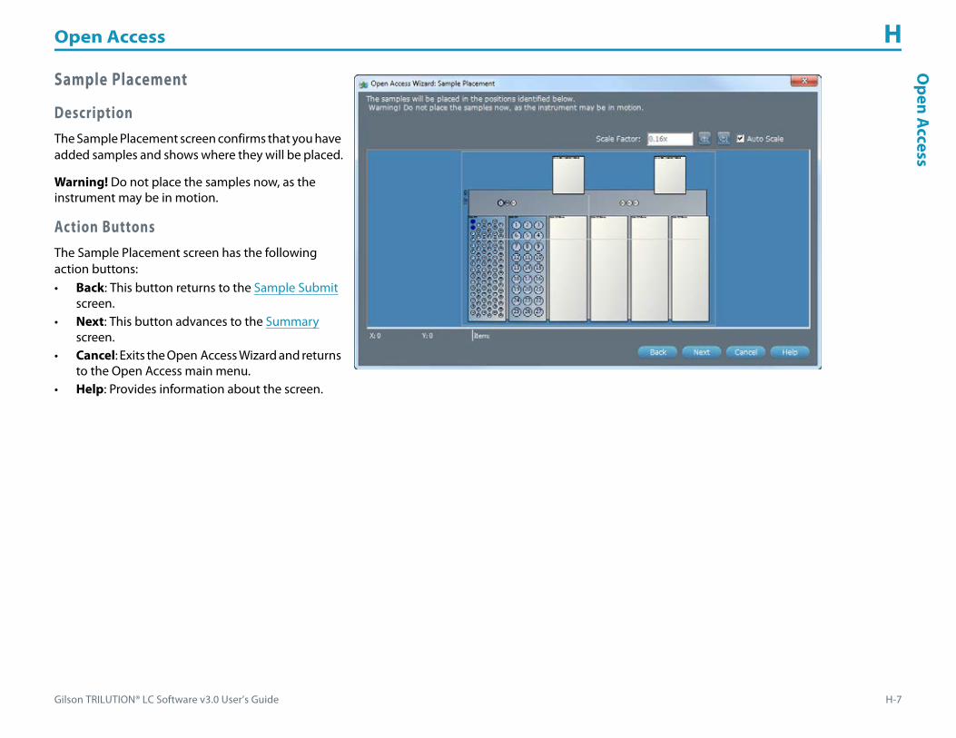
Gilson TRILUTION® LC Software v3.0 User’s Guide H-7
Open Access HO
penA
ccess
Sample Placement
DescriptionThe Sample Placement screen confirms that you have added samples and shows where they will be placed.
Warning! Do not place the samples now, as the instrument may be in motion.
Action ButtonsThe Sample Placement screen has the following action buttons:• Back: This button returns to the Sample Submit
screen.• Next: This button advances to the Summary
screen.• Cancel: Exits the Open Access Wizard and returns
to the Open Access main menu.• Help: Provides information about the screen.

Open Access H
H-8 Gilson TRILUTION® LC Software v3.0 User’s Guide
Ope
nA
cces
s Summary
DescriptionThe Summary screen has the following sections:• Current User: The current user logged in to
TRILUTION LC Open Access.• Number of Samples: The number of samples
that will be run.• Time of Submission: The length of time that
must elapse before samples can be placed for the application run being set up.
• Mobile Phase Status: Lists the volume of mobile phase required based on the number of samples and the flow rate and mobile phase composition set in the method. Also lists the available volume, which is set by clicking Solvent Settings.
• Number of Applications in Queue: The number of applications that must finish running before the current application will begin running.
• Estimated Time to Start: The approximate length of time that will elapse before the current application will begin running.• Estimated Time to Complete: This is a length of time equal to the Estimated Time to Start + (Run Time * Number of Samples).
Action ButtonsThe Summary screen has the following action buttons:• Solvent Settings: Allows you to indicate the volume of reservoir solvent; uses your unit settings for volume for the unit of measure. • Back: Returns to the Sample Placement screen.• Finish: Exits the Open Access Wizard and displays the Submission of Sample(s) screen, if the instrument is ready to accept the samples.• Cancel: Exits the Open Access Wizard and returns to the Open Access main menu.• Help: Provides information about the screen.

Gilson TRILUTION® LC Software v3.0 User’s Guide H-9
Open Access HO
penA
ccess
Submission of Sample(s)
DescriptionThe Submission of Sample(s) screen shows where samples should be placed.
Action ButtonsThe Submission of Sample(s) screen has the following action button:• OK: This button starts the application running
and advances to the queue listing in the Open Access Application window.
Queue Listing in the Open Access Application Window

Open Access H
H-10 Gilson TRILUTION® LC Software v3.0 User’s Guide
Ope
nA
cces
s Free Wells
Description
The Free Wells dialog is accessed by double-clicking a completed application in the Open Access Application window. It shows you where your samples were and where your fractions are. Use this screen to free those wells for use by other applications. You will not be able to free wells that are used in a running application.
Action Buttons
The Free Wells dialog has the following action buttons:• Free Wells: Clicking this button lets the software know that the wells
previously used by the selected application are now available for use by other applications and it closes the dialog.
• Cancel: Exits the Free Wells dialog without freeing the wells.
The queue will indicate if there are free wells pending.

Gilson TRILUTION® LC Software v3.0 User’s Guide H-11
Open Access HO
penA
ccess
When the Application Run finishes, you will be prompted to remove the vessels.

Gilson TRILUTION® LC Software v3.0 User’s Guide I-1
Electronic Record Management (ERM) Features I
The implementation of an electronic record management system can be complex. TRILUTION LC can assist chromatographers in attaining 21 CFR Part 11 compliance through the implementation of Electronic Record Management (ERM). The ERM features allow electronic records security and tracking (audit trails) and electronic signatures, as well as permitting customized user access levels within the software.
This appendix provides information about the following:• ERM Administration• Users and Groups• Share
For information about activating the ERM features, refer to ERM on page 1-12.

Electronic Record Management (ERM) Features I
I-2 Gilson TRILUTION® LC Software v3.0 User’s Guide
Elec
tron
ic R
ecor
d M
anag
emen
t(ER
M) F
eatu
res ERM Administration
ERM Features are accessed from the Liquid Chromatography|Utilities|ERM|ERM Features menu by a user assigned to the default Admin group. In this dialog, choose whether to enable electronic record management (ERM) features. Check boxes default cleared, thus ERM defaults disabled. When Enable ERM Features is selected, the Audit log is enabled. When Enable Signature Points is selected, a signature will be required by every user for every save. These signatures will be tracked in the E-Signature log.
For information on how to set up users and groups, refer to Users and Groups on page 1-16
Users and GroupsDuring the software installation, by default, two groups are created: Admin and Analyst. “Administrator” is the default user in the Admin group. The Admin group is assigned all the rights. “Analyst” is the default user in the Analyst group. The Analyst group can view, create, and modify in the software.
ShareTo enable other users to view or modify a project, it must be shared. Once shared, the logged in user can act on the project per the permissions assigned to that user’s group. For example, a user with the Modify Project Library permission can make changes to a project that has been shared with him.
To share a project, the user must have the View and Modify permissions for the Project Library. He can then share any projects he has access to (he created them or they have been shared with him).
Note: Shared projects can only be deleted by the user who created the project regardless of whether another user has Delete permissions in the Project Library.
Group Default Permissions
Admin
• Create
• Modify
• Delete
• View
• Import
• Export
• Run
Analyst
• Create
• Modify
• View
• Run

Gilson TRILUTION® LC Software v3.0 User’s Guide J-1
Gilson Server Settings J
The COM port and baud rate for GSIOC communication can be set through GSIOC Server Settings.
To change the COM port or baud rate:
1 Right-click on the Server icon ( ) in the task bar and then select Settings from the menu. Note: Settings cannot be changed if the server is being used by a Gilson program (for example, the GSIOC Utility).
2 In the Port box, select the computer’s serial communications (COM) port to which the Gilson interface instrument is connected.
3 In the Baud box, select 19200 or 9600 to set the baud. The baud is the rate of data transmission between the computer and the Gilson instrument.
4 Click OK to save the changes.
Gilson TRILUTION® LC Software v3.0 User’s Guide K-1
GSIOC Utility K
The GSIOC Utility allows you to issue commands to Gilson GSIOC instruments. Your local Gilson representative may ask you to use this utility to verify that an instrument is connected correctly to the computer. For communication to occur, the Gilson instrument must be connected via an RS-232 connection to the computer or connected via a GSIOC connection to a Gilson interface instrument that is connected to the computer.

GSIOC Utility K
K-2 Gilson TRILUTION® LC Software v3.0 User’s Guide
GSI
OC
Uti
lity Start the GSIOC Utility
To start the GSIOC Utility:
1 Locate the GSIOC Utility (GSUTIL32.EXE) using Windows Explorer or the shortcut at Start > All Programs > Gilson Applications > Utilities > GSIOC Utility. The default installation path on a Windows® 7 (32--bit) system is C:\Program Files\Gilson\Utilities. The default installation path on a Windows® 7 (64-bit) system is C:\Program Files (x 86)\Gilson\Utilities.
2 Start the utility. The Gilson GSIOC Utility window appears.
Review the Port and Baud InformationIn the Gilson GSIOC Utility window, review the COM port and baud information. If any information is incorrect or missing, close the GSIOC Utility and use the GSIOC Server Settings to update the information.
List GSIOC InstrumentsUsing the GSIOC Utility, you can determine the instruments currently connected to the computer.
In the Mode menu, select Scan!
The Unit ID list box displays the unit IDs and the version of the connected instruments. If any connected instruments are missing from the list, ensure that the proper RS-232 or GSIOC connection exists between the computer and the instruments, and that the instruments do not have duplicate unit ID numbers.

Gilson TRILUTION® LC Software v3.0 User’s Guide K-3
GSIOC Utility KG
SIOC U
tility
Basic ModeIn the Basic mode, immediate and buffered GSIOC commands can be sent to specific Gilson instruments.
Review the Port, IRQ, and Baud information in this window. If any information is incorrect or missing, close the GSIOC Utility and use the GSIOC Server Settings to update the information.
There are two drop-down menus in the Basic mode of the Gilson GSIOC Utility: Mode Menu and Help Menu.
Basic Mode Buttons and Features
Immediate ButtonSends an immediate command to the Unit ID selected.
Immediate commands request status information from an instrument. These commands are executed immediately, temporarily interrupting any command in progress. Each command is a string of no more than 40 characters.
A list of valid immediate commands for each instrument is available in its commands list or user’s guide.
Buffered ButtonSends a buffered command to the Unit ID selected.
Buffered commands send instructions to an instrument. These commands are executed one at a time. Each command is a string of no more than 40 characters.
A list of valid buffered commands for each instrument is available in its commands list or user’s guide.
Command FieldThe Command field is where the command to be sent is specified. For more information on sending commands, refer to Send an Immediate Command or Send a Buffered Command.
Response FieldThe Response field is where the response to an immediate or buffered command is displayed.
The response to a successfully completed buffered command is “ok”.
The response to an unsuccessfully completed immediate or buffered command is “#error”.
A list of valid responses to commands for each instrument is available in its commands list or user’s guide.

GSIOC Utility K
K-4 Gilson TRILUTION® LC Software v3.0 User’s Guide
GSI
OC
Uti
lity Basic Mode Menus
Mode MenuThere are three options in the Mode menu: Scan!, Advanced, and Ghost.
Scan!
The Scan! option on the Mode menu allows you to scan for GSIOC instruments. After a scan, the Unit ID list box displays the unit IDs and the version of the connected instruments. If any connected instruments are missing from the list, ensure that the proper RS-232 or GSIOC connection exists between the computer and the instruments, and that the instruments do not have duplicate Unit ID numbers.
Advanced
The Advanced option in the Mode menu allows you to switch between the Basic and Advanced modes. A check mark means that the GSIOC Utility is in Advanced mode.
Ghost
The Ghost option in the Mode menu makes the GSIOC Utility window transparent (and always on top). This allows you to view another window behind the utility. The utility will remain fully functional in the Ghost mode.
Help Menu
About...
When selected, the About window appears.
This window displays the version of the Gilson GSIOC Utility, the GSIOC32.DLL, and the GSIOC Server. It also displays the Port, IRQ, and Baud set by the GSIOC Server Settings.

Gilson TRILUTION® LC Software v3.0 User’s Guide K-5
GSIOC Utility KG
SIOC U
tility
Advanced ModeIn the Advanced mode, immediate and buffered GSIOC commands can be sent to specific Gilson instruments. In this mode, immediate and buffered commands with comments can be saved to a command list to be used as needed. The command lines can be repeated automatically to monitor the status of the instrument.
Review the Port, IRQ, and Baud information by selecting About... from the Help menu. If any information is incorrect or missing, close the GSIOC Utility and use the GSIOC Server Settings to update the information.
There are four drop-down menus in the Advanced mode of the Gilson GSIOC Utility: File Menu, Edit Menu, Mode Menu, and Help Menu.
Advanced Mode Buttons and Features
+ Button
The next to is used to insert an immediate command in the command list. For more information, refer to Insert an Immediate Command.
The next to is used to insert a buffered command in the command list. For more information, refer to Insert a Buffered Command.
Arrow Up or Arrow Down Button
These buttons ( or ) are used to change the position of a command in the command list.
How to Move a Command
Highlight the command in the command list and use to move the command up in the list or to move the command down in the list.
Immediate ButtonSends an immediate command to the Unit ID selected. The Comment field is not used.
Selecting the Immediate button will not add the command to the command list.
For more information, refer to Send an Immediate Command.

GSIOC Utility K
K-6 Gilson TRILUTION® LC Software v3.0 User’s Guide
GSI
OC
Uti
lity Buffered Button
Sends a buffered command to the Unit ID selected. The Comment field is not used.
Selecting the Buffered button will not add the command to the command list.
For more information, refer to Send a Buffered Command.
Response FieldThe Response field is where the response to an immediate or buffered command is displayed.
The response will become gray after 15 seconds if no response is registered.
The response to a successfully completed buffered command is “ok”.
The response to an unsuccessfully completed immediate or buffered command is “#error”.
A list of valid responses to commands for each instrument is available in its commands list or user’s guide.
How to Send a Command Line
Double-click on the Unit, Type, Command, Response, or Comment field to send the immediate or buffered command for that specific command line.
Command Line Column Headings
Repeat
A green check mark ( ) in the Repeat column means that an immediate command will automatically repeat when the Auto Repeat option is checked. Double-click on the Repeat field to select or deselect the Auto Repeat for that command line.
A yellow check mark ( ) in the Repeat column means that a buffered command will automatically repeat when the Auto Repeat option is checked. Double-click on the Repeat field to select or deselect the Auto Repeat option for that command line.
Unit
This is the Unit ID for the instrument in the command line.
Type
I - Immediate Command, B - Buffered Command
Command
This is the GSIOC command for the command line.
Gilson TRILUTION® LC Software v3.0 User’s Guide K-7
GSIOC Utility KG
SIOC U
tility
Response
This is the GSIOC response when the command line is initiated with a double-click on the Unit, Type, Command, Response, or Comment field. The response will become gray after 15 seconds if no response is registered.
Comment
This is an optional comment that can be added to the command line.
Advanced Mode MenusThere are four drop-down menus in the Advanced mode of the Gilson GSIOC Utility: File Menu, Edit Menu, Mode Menu, and Help Menu.
File MenuThere are four options in the File menu: Open, Save, Save As..., and Exit.
Open
The Open option in the File menu allows you to open previously created command lists (GSUTIL32 files). The extension for a GSUTIL32 file is .GSU.
Save
The save option in the File menu allows you to save the Advanced commands to GSUTIL32.GSU. The GSUTIL32.GSU file is automatically created in the location where GSUTIL32.EXE is stored.
The Advanced commands will automatically be saved to GSUTIL32.GSU if the Gilson GSIOC Utility is exited without saving.
The GSUTIL32. GSU is automatically opened when the Advanced mode is selected from the Mode menu.
Save As...
The Save As... option on the File menu allows you to save the Gilson GSIOC Utility commands that are currently defined. The name and path of the file must be specified.
Exit
The Exit option closes the Gilson GSIOC Utility software.

GSIOC Utility K
K-8 Gilson TRILUTION® LC Software v3.0 User’s Guide
GSI
OC
Uti
lity Edit Menu
There are four options in the Edit Menu: Insert Immediate, Insert Buffered, Selection, and Font....
Insert Immediate
The Insert Immediate option in the Edit menu allows you to insert an immediate command in the command list. The new command will be added to the last line in the command list.
The GSIOC Command will not be inserted if there is already a command line in the list with the same Unit ID and Command.
For more information, refer to Insert an Immediate Command.
Insert Buffered
The Insert Buffered option in the Edit menu allows you to insert a buffered command in the command list. The new command will be added to the last line in the command list.
The GSIOC Command will not be inserted if there is already a command line in the list with the same Unit ID and Command.
For more information, refer to Insert a Buffered Command.
Selection
Delete (Ctrl + D)
Deletes the highlighted command from the command list.
Up (Ctrl + U)
Moves the highlighted command up in the command list.
Down (Ctrl + D)
Moves the highlighted command down in the command list.
Execute (Ctrl + E)
Executes the highlighted command.
Repeat (Ctrl + R)
Adds or removes the repeat option for the highlighted command.
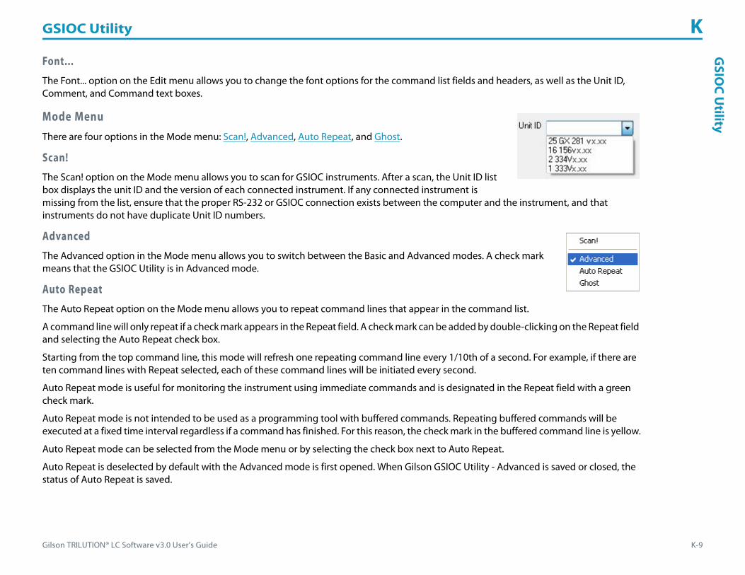
Gilson TRILUTION® LC Software v3.0 User’s Guide K-9
GSIOC Utility KG
SIOC U
tility
Font...
The Font... option on the Edit menu allows you to change the font options for the command list fields and headers, as well as the Unit ID, Comment, and Command text boxes.
Mode MenuThere are four options in the Mode menu: Scan!, Advanced, Auto Repeat, and Ghost.
Scan!
The Scan! option on the Mode menu allows you to scan for GSIOC instruments. After a scan, the Unit ID list box displays the unit ID and the version of each connected instrument. If any connected instrument is missing from the list, ensure that the proper RS-232 or GSIOC connection exists between the computer and the instrument, and that instruments do not have duplicate Unit ID numbers.
Advanced
The Advanced option in the Mode menu allows you to switch between the Basic and Advanced modes. A check mark means that the GSIOC Utility is in Advanced mode.
Auto Repeat
The Auto Repeat option on the Mode menu allows you to repeat command lines that appear in the command list.
A command line will only repeat if a check mark appears in the Repeat field. A check mark can be added by double-clicking on the Repeat field and selecting the Auto Repeat check box.
Starting from the top command line, this mode will refresh one repeating command line every 1/10th of a second. For example, if there are ten command lines with Repeat selected, each of these command lines will be initiated every second.
Auto Repeat mode is useful for monitoring the instrument using immediate commands and is designated in the Repeat field with a green check mark.
Auto Repeat mode is not intended to be used as a programming tool with buffered commands. Repeating buffered commands will be executed at a fixed time interval regardless if a command has finished. For this reason, the check mark in the buffered command line is yellow.
Auto Repeat mode can be selected from the Mode menu or by selecting the check box next to Auto Repeat.
Auto Repeat is deselected by default with the Advanced mode is first opened. When Gilson GSIOC Utility - Advanced is saved or closed, the status of Auto Repeat is saved.

GSIOC Utility K
K-10 Gilson TRILUTION® LC Software v3.0 User’s Guide
GSI
OC
Uti
lity Ghost
The Ghost option in the Mode menu makes the GSIOC Utility window transparent (and always on top). This allows you to view another window behind the utility. The utility will remain fully functional in the Ghost mode.
Help Menu
About...
When selected, the About window appears.
This window displays the version of the Gilson GSIOC Utility, the GSIOC32.DLL, and the GSIOC Server. It also displays the Port, IRQ, and Baud set by the GSIOC Server Settings.

Gilson TRILUTION® LC Software v3.0 User’s Guide K-11
GSIOC Utility KG
SIOC U
tility
Commands
Immediate CommandImmediate commands request status information from an instrument. These commands are executed immediately, temporarily interrupting any command in progress. Each command is a string of no more than 40 characters.
A list of valid immediate commands for each instrument is available in its commands list or user’s guide.
Buffered CommandBuffered commands send instructions to an instrument. These commands are executed one at a time. Each command is a string of no more than 40 characters.
A list of valid buffered commands for each instrument is available in its commands list or user’s guide.
Insert an Immediate CommandThere are two ways to insert an immediate command in Advanced mode.
Using the Edit Menu1 From the Unit ID drop-down box, select the unit ID of the instrument to which the command will be sent.2 Type a Command and Comment. (The comment is optional.)3 Select Insert Immediate from the Edit menu. The new command will be inserted at the bottom of the command list.
Note: The command will not be inserted if there is already a command line in the list with the same Unit ID and command.
Using the + Button1 From the Unit ID drop-down box, select the unit ID of the instrument to which the command will be sent.2 Type a Command and Comment. (The comment is optional.)
3 Click the button next to the Immediate button. The new command will be inserted at the bottom of the command list.
Note: The command will not be inserted if there is already a command line in the list with the same Unit ID and command.

GSIOC Utility K
K-12 Gilson TRILUTION® LC Software v3.0 User’s Guide
GSI
OC
Uti
lity Insert a Buffered Command
There are two ways to insert a buffered command in Advanced mode.
Using the Edit Menu1 From the Unit ID drop-down box, select the unit ID of the instrument to which the command will be sent.2 Type a Command and Comment. (The comment is optional.)3 Select Insert Buffered from the Edit menu. The new command will be inserted at the bottom of the command list.
Note: The command will not be inserted if there is already a command line in the list with the same Unit ID and command.
Using the + Button1 From the Unit ID drop-down box, select the unit ID of the instrument to which the command will be sent.2 Type a Command and Comment. (The comment is optional.)
3 Click the button next to the Buffered button. The new command will be inserted at the bottom of the command list.
Note: The command will not be inserted if there is already a command line in the list with the same Unit ID and command.
Send an Immediate Command
Basic Mode1 From the Unit ID drop-down box, select the unit ID of the instrument to which the command will be sent.2 Type (or select) a Command.3 Click .
Advanced Mode
Using the Button1 From the Unit ID drop-down box, select the unit ID of the instrument to which the command will be sent.2 Type a Command and Comment. (The comment is optional.)3 Click .
Using Execute from the Edit Menu1 Highlight the command to be sent in the command list.2 Choose Selection from the Edit menu and select Execute. (Alternatively, type Ctrl + E.)

Gilson TRILUTION® LC Software v3.0 User’s Guide K-13
GSIOC Utility KG
SIOC U
tility
Using the Command List
Double-click on the command line of the command to send.
Send a Buffered Command
Basic Mode1 From the Unit ID drop-down box, select the unit ID of the instrument to which the command will be sent.2 Type (or select) a Command.3 Click .
Advanced Mode
Using the Button1 From the Unit ID drop-down box, select the unit ID of the instrument to which the command will be sent.2 Type a Command and Comment. (The comment is optional.)3 Click .
Using Execute from the Edit Menu1 Highlight the command to be sent in the command list.2 Choose Selection from the Edit menu and select Execute. (Alternatively, type Ctrl + E.)
Using the Command List
Double-click on the command line of the command to send.

Gilson TRILUTION® LC Software v3.0 User’s Guide L-1
Reference Information L
This appendix contains miscellaneous reference information for TRILUTION LC users.

Reference Information L
L-2 Gilson TRILUTION® LC Software v3.0 User’s Guide
Refe
renc
e In
form
atio
n 402 Pump Dual with Tee OperationThe 402 Dual with Tee is a uniquely designed syringe pump that allows for two different syringe sizes to function as one syringe pump.
For the syringe pump to function properly, the following will be true:• The left syringe capacity is greater than the right syringe capacity.
The following describes how the syringes work together:
Aspirate (Tray)• The valve must be in the probe position.• The right syringe will be used if the requested volume is less than 95% of the right syringe capacity. Held volume is considered.• The left syringe will be used if the requested volume is 95% or greater than the right syringe capacity.
Aspirate (Reservoir)• The valve must be in the reservoir position• The left syringe will be used.
Dispense• The right syringe will be used if the requested volume is less than 95% of the right syringe capacity. Held volume is considered.• The left syringe will be used if the requested volume is 95% or greater than the right syringe capacity.
For a list of supplied tasks for the 402 Pump Dual with Tee, refer to 402 Pump Single, 402 Pump Dual, and 402 Pump Dual with Tee Tasks on page A-66.

Gilson TRILUTION® LC Software v3.0 User’s Guide L-3
Reference Information LReference Inform
ation
CompressibilityThe following table provides the compressibility values for some common mobile phase solvents.
Compressibility
Instrument
30X-Series Pumps 32X- and 33X-Series Pumps
Solvent Temperature (ºC) Compressibility (Mbar-1) Temperature (ºC) Compressibility (Mbar-1)
Water
20253040
46464545
20–23ºC 34
Methanol
20253040
121–123125–127129–130
138
20–23ºC 162
Benzene
20253040
94–9596–97
101–103110
20–23ºC
Chloroform
20253040
97–10197
108–110118–119
20–23ºC 204
Methylene Chloride 25 97 20–23ºC
Carbon Tetrachloride
20253040
103–105106–108112–113120–122
20–23ºC
Ethanol
20253040
110–112114–116118–119126–127
20–23ºC 148
Acetone
20253040
126–127124133
144–156
20–23ºC
n-Heptane
20253040
140–145142–149150–155
160
20–23ºC 270
Compressibility (Page 1 of 2)
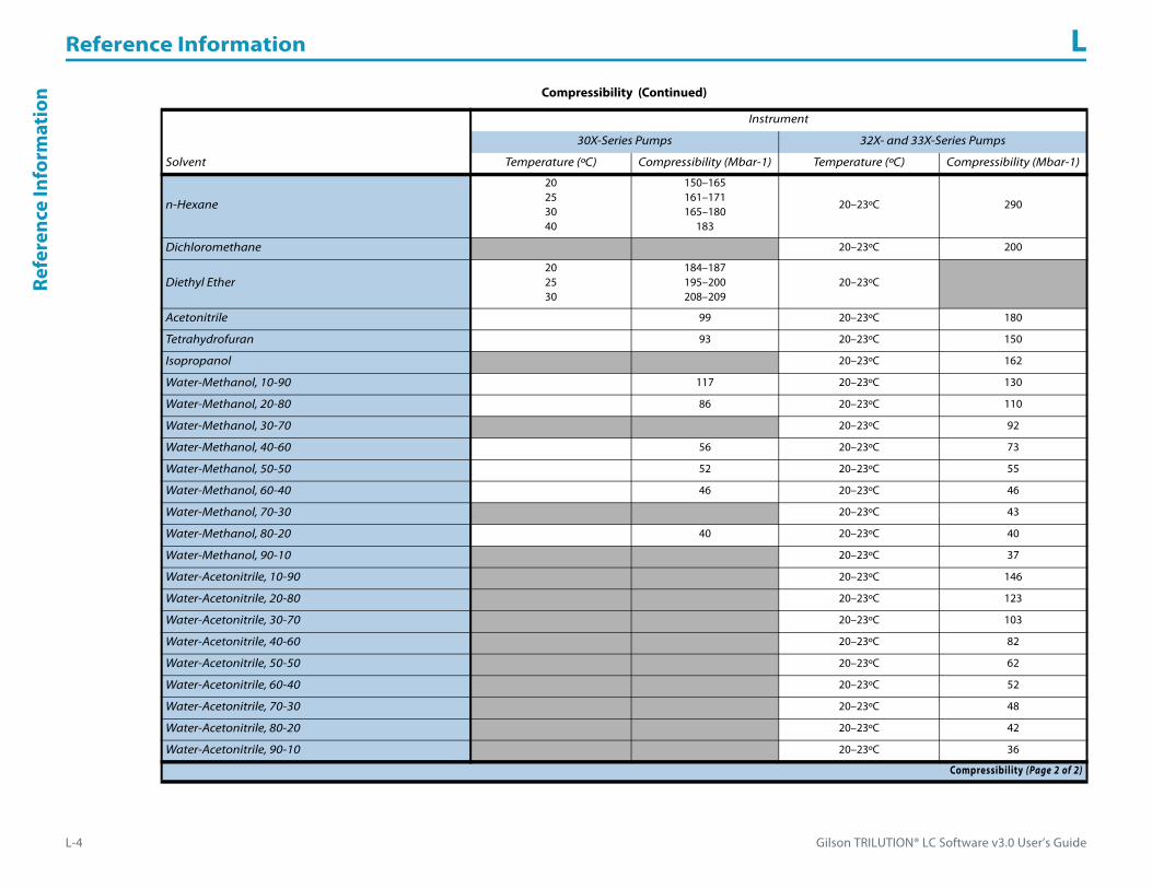
Reference Information L
L-4 Gilson TRILUTION® LC Software v3.0 User’s Guide
Refe
renc
e In
form
atio
n
n-Hexane
20253040
150–165161–171165–180
183
20–23ºC 290
Dichloromethane 20–23ºC 200
Diethyl Ether202530
184–187195–200208–209
20–23ºC
Acetonitrile 99 20–23ºC 180
Tetrahydrofuran 93 20–23ºC 150
Isopropanol 20–23ºC 162
Water-Methanol, 10-90 117 20–23ºC 130
Water-Methanol, 20-80 86 20–23ºC 110
Water-Methanol, 30-70 20–23ºC 92
Water-Methanol, 40-60 56 20–23ºC 73
Water-Methanol, 50-50 52 20–23ºC 55
Water-Methanol, 60-40 46 20–23ºC 46
Water-Methanol, 70-30 20–23ºC 43
Water-Methanol, 80-20 40 20–23ºC 40
Water-Methanol, 90-10 20–23ºC 37
Water-Acetonitrile, 10-90 20–23ºC 146
Water-Acetonitrile, 20-80 20–23ºC 123
Water-Acetonitrile, 30-70 20–23ºC 103
Water-Acetonitrile, 40-60 20–23ºC 82
Water-Acetonitrile, 50-50 20–23ºC 62
Water-Acetonitrile, 60-40 20–23ºC 52
Water-Acetonitrile, 70-30 20–23ºC 48
Water-Acetonitrile, 80-20 20–23ºC 42
Water-Acetonitrile, 90-10 20–23ºC 36
Compressibility (Continued)
Instrument
30X-Series Pumps 32X- and 33X-Series Pumps
Solvent Temperature (ºC) Compressibility (Mbar-1) Temperature (ºC) Compressibility (Mbar-1)
Compressibility (Page 2 of 2)

Gilson TRILUTION® LC Software v3.0 User’s Guide L-5
Reference Information LReference Inform
ation
How to Calculate Fraction Collection Delay VolumeDelay Volume is the volume in the flow path between the detector flow cell outlet and the inlet of the fraction collection valve.
Contact your local Gilson representative for help determining the value to enter for the system configuration.
Gilson LC/MS Purification System Fraction Collection Delay VolumeFor a configuration in which a channel on the Flexar SQ 300 MS Detector is the primary channel (for fraction collection), the fraction collection delay volume must be calculated using the following equation:
Fraction Collection Delay Volume = Fraction Collection Delay Volume (determined by your local Gilson representative)+ [Time needed to align MS peaks with UV peaks * Mobile Phase Flow Rate]

Reference Information L
L-6 Gilson TRILUTION® LC Software v3.0 User’s Guide
Refe
renc
e In
form
atio
n Recommended Maximum Scan Range(High m/z – Low m/z)Refer to the following table when setting the scan range for the Flexar SQ 300 MS Detector. Gilson recommends that the difference between the high end of the scan range and the low end of the scan range not exceed the values below:
Recommended Maximum Scan Range (High m/z – Low m/z)
Data Rate(Data points per second)
Scan without SIM Channels Scan with SIM Channels
10 357 m/z 242 m/z
5 (Default) 714 m/z 515 m/z
2 1785 m/z 1321 m/z
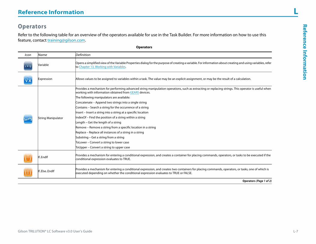
Gilson TRILUTION® LC Software v3.0 User’s Guide L-7
Reference Information LReference Inform
ation
OperatorsRefer to the following table for an overview of the operators available for use in the Task Builder. For more information on how to use this feature, contact [email protected].
Operators
Icon Name Definition
Variable Opens a simplified view of the Variable Properties dialog for the purpose of creating a variable. For information about creating and using variables, refer to Chapter 13, Working with Variables.
Expression Allows values to be assigned to variables within a task. The value may be an explicit assignment, or may be the result of a calculation.
String Manipulator
Provides a mechanism for performing advanced string manipulation operations, such as extracting or replacing strings. This operator is useful when working with information obtained from GEARS devices.
The following manipulators are available:
Concatenate – Append two strings into a single string
Contains – Search a string for the occurrence of a string
Insert – Insert a string into a string at a specific location
IndexOf – Find the position of a string within a string
Length – Get the length of a string
Remove – Remove a string from a specific location in a string
Replace – Replace all instances of a string in a string
Substring – Get a string from a string
ToLower – Convert a string to lower case
ToUpper – Convert a string to upper case
If..EndIf Provides a mechanism for entering a conditional expression, and creates a container for placing commands, operators, or tasks to be executed if the conditional expression evaluates to TRUE.
If..Else..EndIf Provides a mechanism for entering a conditional expression, and creates two containers for placing commands, operators, or tasks, one of which is executed depending on whether the conditional expression evaluates to TRUE or FALSE.
Operators (Page 1 of 2)

Reference Information L
L-8 Gilson TRILUTION® LC Software v3.0 User’s Guide
Refe
renc
e In
form
atio
n
Do Only In
Creates a container for placing commands, operators, or tasks, which will be executed only in the circumstance specified within the operator (for example, executing a Prime Task in the First Method Iteration only).
Tasks, commands, and operators within the Do Only In container will be executed per the option selected.
The following options are available:
First Method Iteration
Last Method Iteration
Volume To Aspirate
First Intelligent Itn
Last Intelligent Itn
Loop Creates a container for placing commands, operators, or tasks , which will be executed in succession for the specified number of loop iterations (Loop Count).
Label Creates a location within a task or method that can be referenced by a Goto Operator within the same task or method.
Goto Instructs the task or method to continue operation at the location of the specified Label within the same task or method.
Operators (Continued)
Icon Name Definition
Operators (Page 2 of 2)

Gilson TRILUTION® LC Software v3.0 User’s Guide L-9
Reference Information LReference Inform
ation
OriginThe origin is a reference used when creating custom templates using the Bed Layout and Utilities. For more information, refer to How to Create a Template on page G-2.
Origin (X Origin=0, Y Origin=0, Z Origin=0)

Reference Information L
L-10 Gilson TRILUTION® LC Software v3.0 User’s Guide
Refe
renc
e In
form
atio
n
Move X-285 and Y-165
Origin (Default Settings Applied)

Gilson TRILUTION® LC Software v3.0 User’s Guide L-11
Reference Information LReference Inform
ation
IconsThe following are icons that appear several places in the software. Refer to the table below for a description of the function of each.
Icon Description
Select all
Clear all
Invert selection

Reference Information L
L-12 Gilson TRILUTION® LC Software v3.0 User’s Guide
Refe
renc
e In
form
atio
n Zoom• To zoom, toggle the Auto Scale selection off.
• To zoom in, click once or repeatedly. The software will zoom in to the center of the cross hairs. Move the cross hairs by scrolling the window.
• To zoom out, click once or repeatedly.• To zoom to a specific scale factor, enter the number in the Scale Factor field.