versitron - hardness testers · versitron rockwell hardness testing system newage hardness testing...
TRANSCRIPT

VERSITRON®Rockwell Hardness Testing System
OPERATION MANUALModels AT130-RDS and AT130-SRDS
Version 4.3 Rev. 11/11

®Versitron is a registered trademark of Newage Testing Instruments.
.

Contents1. BEFORE YOU BEGIN ..................................................................................................................................... 5
2. TEST METHOD ............................................................................................................................................... 62.1 ASTM E-18: Rockwell Hardness Testing ...................................................................................................... 62.2 Top-loading and Test Surface Referencing .................................................................................................. 62.3 Unique Benefits to Keep In Mind ................................................................................................................. 7
3. INSTALLATION AND SETUP .......................................................................................................................... 83.1 Test Stand Installation .................................................................................................................................. 83.1.1 Positioning Stands, Models AT130-N & AT130-T ..................................................................................... 83.1.2 Bolting the Bench Stands ......................................................................................................................... 83.2 Install Operating Lever on Non-Automatic Tester ........................................................................................ 93.3 Install the Test Heads .................................................................................................................................. 93.3.2 Automatic Systems, Testers with AT130-MT1, AT130-MT2, or AT130-MT3 Option ............................... 103.3.3 Dual Head Systems - Model AT130-2DS ................................................................................................ 10
4 TESTER OPERATION .................................................................................................................................... 114.1 General Procedures .................................................................................................................................... 114.1.1 Basic Operation ....................................................................................................................................... 114.1.1.1 All Manual or Automatic Bench Stands................................................................................................ 114.1.2 Changing Scales ..................................................................................................................................... 134.1.2.1 Changing Scale Displays ...................................................................................................................... 134.1.2.2 Changing Indenters .............................................................................................................................. 144.1.2.3 Changing Load Selections ................................................................................................................... 154.1.2.4 Calibration ............................................................................................................................................ 154.1.2.5 Load Lock ............................................................................................................................................. 164.1.3 Clamping Shield Operation: Large Parts ................................................................................................. 174.2 Other Procedures ....................................................................................................................................... 174.2.1 Checking Vee Anvil Alignment (for Testing Rounds) ................................................................................ 174.2.1.1 AT130-T Stand; Vee Anvil Adjustment .................................................................................................. 184.2.1.2 AT130-N Stands; Vee Anvil Adjustment ............................................................................................... 194.2.2 Indenter Shroud, Clamping Shield Options ............................................................................................. 194.2.3 Gooseneck for Inside Diameter Testing .................................................................................................. 194.2.4 Testing Tapered Parts - Ball Swivel Anvil (Option) ................................................................................... 194.2.5 Testing Without Anvil Stage, AT130-T Stands ........................................................................................... 24.3 Conditions Necessary for Reliable Test Results ......................................................................................... 214.4 Advanced Digital Keypad, Procedures - Models AT130-RDS, AT130-SRDS ............................................ 214.4.1 List of Individual Key Functions .............................................................................................................. 224.4.2 Security Code Procedure ........................................................................................................................ 234.4.3 Tolerance (TOL) Key Function ................................................................................................................. 244.4.4 Statistic (STAT) Key Functions ................................................................................................................. 254.4.5 Convert (CONV) Key Functions ............................................................................................................... 274.4.6 Print Key Functions ................................................................................................................................. 284.4.7 Sample Printouts ..................................................................................................................................... 31

.
4.4.8 Mode Key Functions ............................................................................................................................... 324.4.9 Calculation (CAL) Key Functions ............................................................................................................. 354.4.10 Zero Set (O SET) Key Function (Optional) ............................................................................................. 374.4.11 Scale Select ........................................................................................................................................... 374.4.12 Digital Readout Codes .......................................................................................................................... 384.4.12.1 Normal Operation Display Codes ....................................................................................................... 384.4.12.2 Operation Error Codes ....................................................................................................................... 384.4.12.3 Error Messages .................................................................................................................................. 39
5. SPECIFICATIONS ......................................................................................................................................... 405.1 Test Stand Specifications ........................................................................................................................... 405.1.1 AT130-T Stands ....................................................................................................................................... 405.1.2 AT130-N Stand ........................................................................................................................................ 405.2 Test Head Specifications ............................................................................................................................ 425.2.1 AT130-RDS, AT130-SRDS Test Heads .................................................................................................... 425.2.2 Electronic Output Specifications ............................................................................................................. 425.3 Standard Accessories ................................................................................................................................ 435.4 Options and Accessories .......................................................................................................................... 43
6 TROUBLESHOOTING & MAINTENANCE ..................................................................................................... 466.1 Maintenance Procedures ........................................................................................................................... 466.2 Troubleshooting .......................................................................................................................................... 466.2.1 What Not To Do ....................................................................................................................................... 466.2.2 What to do Before You Call Newage ....................................................................................................... 466.2.3 Pre-Troubleshooting checklist ............................................................................................................... 466.2.4 Troubleshooting Checklist ....................................................................................................................... 47
7. VERSITRON FACTORY SERVICE & SHIPPING INSTRUCTIONS ................................................................ 508. REFERENCE TABLES, ASTM E-18 .............................................................................................................. 518.1 Rockwell Scale Reference Table ................................................................................................................ 518.2 Minimum Thickness ................................................................................................................................... 518.3 Round Correction ....................................................................................................................................... 528.4 Hardness Converson Chart, High Range ................................................................................................... 538.5 Hardness Converson Chart, Low Range .................................................................................................... 54
APPENDIX A: Gooseneck Fixture: Installation and Operation ......................................................................... 55APPENDIX B: Motor Drive Options .................................................................................................................. 56APPENDIX C: Automatic Head-Height Adjustment Option ............................................................................. 58APPENDIX D: Optional Software Features ....................................................................................................... 59APPENDIX E: Calibration & Service Support ................................................................................................... 70T-stand foot print .............................................................................................................................................. 71N-stand foot print ............................................................................................................................................. 72ONE YEAR LIMITED WARRANTY .................................................................................................................... 73

1. BEFORE YOU BEGIN
The Versitron family of testers uses the most advanced mechanical and digital components on the market to make your testing as simple as possible.
Due to their unique design, these testers are significantly different to install and operate than any other testers. PLEASE READ THROUGH THIS MANUAL CAREFULLY. When beginning to set up and operate your tester follow through sections for the general instructions and then for those sections dealing with your specific model. You need not read through the entire manual.
Section Two is important to read because it clarifies exactly what method these testers use, how they operate, and how it can benefit you.
Section Three is for installation,
Section Four covers operation for all test modes and stands. Also included is a checklist for correct operation.
Section Five identifies all the parts and components described later in the manual as well as the specifications.
Section Six covers all maintenance procedures and a troubleshooting guide if you run into problems.
Section Seven lists service help and shipping procedures if factory service is required.
Section Eight may be helpful as a reference for various aspects of testing. It includes tables from the ASTM standard E-18 for Rockwell testing.
Appendices include descriptions of optional components or software that may have been purchased with this system.

6 - Newage Hardness Testing Versitron Rockwell Hardness Testing System
2. TEST METHOD
2.1 ASTM E-18: Rockwell Hardness Testing
This tester operates according to ASTM E-18 standard in all particulars. It is used by virtually every large automotive, aerospace and defense manufacturer in the nation.
2.2 Top-loading and Test Surface Referencing
The Versitron has two unique features, top-loading and test surface referencing. At the start of the test the entire indenter descends approximately 3/32” to contact the test specimen surface. As the preload and full loads are applied, the indenter shroud contacts the specimen surface.
This shroud establishes a reference point against which the depth of penetration is compared.
This feature reduces or eliminates the effects of deflection of the test stand and specimen under load. With standard testers, deflection in the specimen, elevating screw, or the frame components invalidates the test.
Furthermore, a clamping shield can be used to firmly fix a specimen into position without special fixturing. Since the clamping shield is fixed to the test stand independently of the test head which holds all the measuring and loading components, there is no effect on the test results.

Newage Hardness Testing - 7Versitron Rockwell Hardness Testing System
2.3 Unique Benefits to Keep In Mind
These features of top loading and test-surface referencing provide a number of unique benefits:
Transportability - The tester does not need to be leveled before testing, nor does it need a firm foundation. This means the tester can be placed on a wheeled cart and carried to different test locations such as different furnaces in a heat treating facility.
Operation in bad environments - Dirt, corrosion and oil on the underside of the specimen, anvil, or elevating screw don’t produce bad test results (within certain limits). Even heavy vibration doesn’t upset the test results. This means your maintenance is reduced, reliability is improved, and your tester operations are more flexible.
Reducing operator influence - Since the operator basically puts the part into position and pulls a lever or pushes a button, there is far less possibility of bad test technique affecting the test results. Virtually any operator can get good results right from the start.
Highest possible speed - Single-stroke testing in a couple of seconds, even on manually operated units makes for the fastest possible testing. There’s no impact from the load cell and there’s virtually no set-up time on large parts.
Lower service costs - Since the clamping shield protects the diamond from damage, there’s less breakage expense. The tester can be calibrated in-house and factory service of the interchangeable test heads also reduces costs. Of course, field service is also available through the Newage service network.

8 - Newage Hardness Testing Versitron Rockwell Hardness Testing System
3. INSTALLATION AND SETUP
3.1 Test Stand Installation
The tester is shipped in two crates, one containing the stand with an accessory kit and one containing the test head.
In the Accessory kit should be:
- Set of Allen wrenches - 2” vee anvil
Also included are:- Operating lever (on non-automatic testers only), in crate with stand.- 3” flat anvil and clamping shield, installed on stand- Diamond indenter installed on head
Other optional components may also be included. Please check that these items and others listed on the packing slip are present in the kit.
Unpack all the materials. AT130-T stands are bolted to the base of the crate. (Save the packing materials for possible future return shipping for factory service.)
3.1.1 Positioning Stands, Models AT130-N & AT130-T
Position the test stand in the desired location. Screw in the height adjustment knob on AT130-T stands. For bench models the base under the tester should provide a 3” wide hole directly underneath the acme-thread elevating screw to permit the elevating screw to descend to its lowest position. (For dimensions refer to the specification section.) To position the tester over the hole, lower the elevating screw by turning the height adjusting wheel counter-clockwise. If the elevating screw is not properly centered over the hole, the elevating screw will only descend a few inches before the height adjusting wheel starts to ride up the elevating screw. Reposition the stand. The elevating screw will drop down when positioned properly.
3.1.2 Bolting the Bench Stands
For testing on small parts the stand does not normally need to be bolted down. However, if the tester is to be used on a mobile cart, with large test specimens or in a location where it might otherwise be knocked over, it must be bolted down. N-stands have three threaded holes that must be accessed from underneath.
- Spot anvil - Test blocks- Wrench to remove elevating unit- Pin wrench
Positioning Bench Stands l-Elevating screw 2-Elevating screw height adjuster 3-Stand base 4-Head carriage height adjustment knob
- Small vee anvil - 1/16” ball indenter - Anvil base collet- Calibration block- Vinyl protective cover

Newage Hardness Testing - 9Versitron Rockwell Hardness Testing System
3.2 Install Operating Lever on Non-Automatic Tester
The operating lever should be slipped into the split lever casing. Tighten the thumbscrews on the casing finger-tight.
Slip the operating lever assembly onto the lever spine so the lever is leaning back about 10 degrees at the resting position. Install the lever screw and washer to tighten the lever assembly to the stand. The normal rest position of the lever is shown In the photo. (Note the top position setting.) If the lever is pressed against the stop (see arrow), it should slip with 10 pounds force on the end of the lever. The split casing acts as a clutch to prevent excessive force. It is normally set correctly at the factory but if it is too loose, tighten the Allen screw that tightens the split casing.
If the Allen set screw is set too tightly, a second stress reliever in the lever stop will slip. To realign it, slightly loosen the 3 holding screws and line up the red screw with the red dot on the collar. Resecure the 3 screws firmly.
3.3 Install the Test Heads
All test heads are installed into the test stands in the same manner. They are designed for quick installation and removal. This feature facilitates scale changeover from regular to superficial Rockwell and facilitates service.
Make sure the area where the test head sits is clean. Lower the elevating screw. Remove the clamping shield. Loosen the head lock Allen screw.
Rotate the pressure knobs so that one is in line with the load plate. On digital units there is a preload switch case next to one pressure knob. In this case, keep the case toward the front.
With the load plate facing the same direction as the stand, carefully set the test head into the stand with the indenter assembly over the indenter hole. Set the indenter assembly into the indenter hole area and lean the test head upright while settling the head into position. Be sure not to damage the indenter by making contact with the stand.
Lift the pressure yoke and rotate the pressure knobs so the pressure yoke rests on each knob. (If a motor drive is installed, it may be necessary to push down on the top of the test head while rotating the pressure knobs in order to get enough clearance to be able to rotate the knobs.) Orient the load plate to face frontward while holding the knobs into position. On manually operated units, pull the operating lever down to the stop position and tighten the head lock Allen screw while holding the lever down. On automatic units, press the top of the test head down by hand until it bottoms out, then tighten the head lock Allen screw. (To remove the test head the procedure is reversed.) The entire procedure should take a few seconds, once it has been repeated a few times.Attach all the connections at the back of the test head. They
Set Test Head into Position1-Load plate2-Pressure knob3-Pressure yoke4-Preload switch5-Front of stand6-Elevating screw7-Head lock allen screw

10 - Newage Hardness Testing Versitron Rockwell Hardness Testing System
are all in labeled positions. Each connection is keyed so that only the proper male and female ends will fit. Attach the power cable and plug it into the power source. Attach the preload switch cable running from the bottom of the test head. Attach a printer cable (optional) to a printer or other RS-232 compatible device.
3.3.2 Automatic Systems, Testers with AT130-MT1, AT130-MT2, or AT130-MT3 Option
Automatic systems are shipped already assembled. Be sure to plug in power cables running from the motor into the test head. One cable is for motor control and one for motor drive. On air drive models connect air to regulator on back of stand (See Appendices).
3.3.3 Dual Head Systems - Model AT130-2DS
Dual digital head systems use a single electronic head with dual load cells.
Fasten the bracket to the side of the tester using the [2] allen screws provided. Attach the bracket flange on the underside of the electronic package using allen screws. Mount the bracket arm to the block and flange. Then follow the procedure for test head setup as described in the previous section. Also, plug in connectors from the load cell to the electronic unit and to the power and optionally to the motor drive.
4 TESTER OPERATION
Hook Up Connectors1-Fuse*2-Remote pedal start 3-Power switch*4-Motor limit switch*5-Motor or solenoids 6-Printer 7-Preload switch 8-Power cord 9-Model & Serial #*Automatic unit only
Dual Head Set Up1-Load cell2-Electronic package3-Holding arm4-Flange5-Bracket
12
3
4
5

Newage Hardness Testing - 11Versitron Rockwell Hardness Testing System
4.1 General Procedures
This is a top-loaded Rockwell Hardness Testing system. Therefore, with one downward lever motion the preload, zero set, and full load are applied automatically. Raising the lever to the reading position removes the full load and provides a hardness test result. Your anvil is only a means of support for the test piece, not a preload set. Therefore, the anvil is not sensitive to dirt or grease and less surface preparation is necessary on the opposite side of test surface than with other testers. In addition, test cycle time is reduced greatly, especially with parts of similar size, because the anvil height need not be adjusted from one test to the next.
Please note: It is important that the tester only be used with the indenter shroud attached.
4.1.1 Basic Operation
4.1.1.1 All Manual or Automatic Bench Stands
Your tester should be installed before proceeding and the test head set up for operation with a diamond indenter in place (See Section 3.)
1 Check to make sure a diamond indenter is installed in the test head. If not, refer to the next section for installing indenters. BE SURE THE INDENTER SHROUD IS INSTALLED.
2 Put the two inch flat anvil in the elevating screw and place a Rockwell C test block on the anvil (Or Rockwell N block if using a superficial head.)
3. Raise the elevating screw by turning the height adjuster until the test specimen touches the clamping shield (if the clamping shield is being used) or until it is within 1/16” of the indenter. (The test piece should not touch the indenter.) If the elevating screw will not raise high enough when using an AT130-T stand, loosen the lock knob at the right rear of the stand and turn the height adjustment knob at the top-back of the stand to lower the test head position.
4. Turn the power switch on at the back of the test head. The display will read:
SELF TEST
5. Wait a few seconds until the display changes to show the scale and status. For example:
HRC READY
Basic Operation1-Elevating screw2-Elevating screw height adjuster3-Lock knob4-Head carriage height adjustment knob5-Anvil6-Indenter shroud
Load Lever Operation

12 - Newage Hardness Testing Versitron Rockwell Hardness Testing System
6. For manually operated testers, pull the load lever forward until it stops. Hold the lever down until time reaches zero, then release to remove the load. For automatic units simply press the start “O” button or the optional remote start switch. The display will show the Rockwell test value for example:
HRC 60.3
(There may also be an OK, HI or LO after the result. This indicates that there are tolerance limits set. To reset tolerances refer to the Tolerances Section under keypad operation - Section 4.4.3.
This is the complete test cycle. The operator is now ready to make another test. Proceed to the sections describing load settings, calibration, changing indenters, and advanced digital keypad operation.
Please note: This tester uses a battery which lasts seven years to store readings in memory. If the tester is turned off, the tests in memory and all tolerance and other test parameters will remain in memory.
I-Optional Remote Start Switch2-Motor Drive

Newage Hardness Testing - 13Versitron Rockwell Hardness Testing System
4.1.2 Changing Scales
When changing scales the indenter, load selection, and display must all be changed.
The Versitron does not use dead weights for loading. Its loading mechanism is totally contained within the testing head. Inside is a precision elastic member which has been fatigued many times prior to assembly. The fatiguing gives its “set” position so there is no major deviation during its life. The slight movement required to apply the full load assures consistent and accurate Rockwell measurements. Minor calibration adjustments inherent with all Rockwell testers can be achieved very easily with this system. The preload is preset inside the test head: 3 kg for Rockwell superficial heads, 10 kg for regular Rockwell heads.
4.1.2.1 Changing Scale Displays
Press the SCALE SELECT key. A display will appear such as:
HRC1 YES?
This display allows the operator to select the Rockwell C scale. The 1 indicates the scale sequence number. If the operator holds the SCALE SELECT key down, or presses it again, the display will sequence through all the Rockwell scales in this order.
(Note: If nothing happens when the operator presses the Scale Select key refer to the Security Code Procedure in the Advanced Keypad Operation Section.)
Regular Rockwell Superficial Rockwell 2DS Systems Heads Heads
HRC HR15N HRC, HR15N HRB HR30N HRB, HR30N HRA HR45N HRA, HR45N HRE HR15T HRE, HR15T HRF HR30T HRF, HR30T HR45T HR45T
The operator should press YES when the proper scale is shown. The display will change to read
CLEAR HISTORY?
This is a reminder to the operator that the Memory will be deleted if the scale is changed. Press YES to continue. If the first selection, HRC were chosen the display would change to read.
TYPE=DIAMOND

14 - Newage Hardness Testing Versitron Rockwell Hardness Testing System
The operator must check to make certain diamond indenter is installed. (If not, see next section.) After the correct indenter is installed the operator must press the YES key. After pressing the YES key, the display will change to read:
FORCE=I50 kg
The operator must change the load to 150 kg. (See next section) Then press the YES key again. The display will read:
HRC READY
If the operator presses the NO key at any point during the scale selection sequence, the display will revert to the last scale used.
Please Note: Changing the scales will cause the test results in memory to be erased unless an optional program, called Split Memory, is used. (This optional program is described in the appendices.) This feature ensures that operators will not enter new data into an old data base.
4.1.2.2 Changing Indenters
Note: THE INDENTER SHROUD MUST BE SECURELY IN PLACE WHEN TESTING. The indenter area on your Versitron is different than most testers. An indenter shroud surrounds the indenter to act as a holding device for parts under load and to reference the surface position of the test specimen. It also acts to protect the diamond to an extent. Clamping shields may also be used to hold parts that hang off the edge of the anvil. The clamping shield surrounds the indenter shroud. The following procedure is to be used to change the indenter.
1. Remove the clamping shield, if it is installed. (See Section 4.1.3)
2. Unscrew the indenter shroud. This is done by turning the knurled nut clockwise until it comes loose.
3. Remove the indenter using the pin wrench provided in the accessory case. Insert the pin wrench into the hole or the side of the indenter and unthread to loosen and remove. Take care not to remove or damage the indenter probe that drops down when the indenter is removed. Do not use pliers and avoid damaging the indenter holder area.
4. Choose the correct indenter from Rockwell Scale Table II, Reference Section 8.l. Testers are provided with 1/16” ball indenter and diamond indenter.
5. Make sure the thread, the concave end, and the shoulder of the indenter are clean.
6. Screw in the indenter and make snug with pin wrench.
7. Check to verify that the wavy washer is inside the indenter shroud. Screw on the indenter shroud with cut-away portion facing front (if a cutaway indenter shroud is used). Be sure to screw in until finger tight. Check that the indenter shroud contact points are smooth and clean.
Changing Indenters1 -Indenter2 -Shroud3 -Pin Wrench
I-Knurled nut2-Wavy masher3-Indenter shroud

Newage Hardness Testing - 15Versitron Rockwell Hardness Testing System
8. The shroud and indenter area should be kept free of dirt and grease which could hamper operation.
SPECIAL NOTE ON BALL INDENTERS
Calibration on ball indenter scales is directly related to length of the indenter. When replacement ball indenters are required the purchase order should reference the serial number of the test head (located on chrome capstan wheel). Also note: Balls in the ball indenters can be deformed on harder surfaces. They are easily replaced by unscrewing the indenter cap and replacing the ball. The first test after changing balls must be discounted since it seats the ball in the indenter.
4.1.2.3 Changing Load Selections
The major load is changed by turning the chrome capstan wheel on the test head. As the wheel is turned, the red line on the load plate moves from one load position to another - for example from 150 kg to 100 kg on a regular Rockwell scale head or from 45 kg to 30 kg on a superficial Rockwell scale head. The red line should be approximately centered at the proper load setting hole on the load plate. Then the operator should check the calibration. (See next section.)
To determine the proper load for a given scale, refer to the chart at the back of the Manual (Section 8.1).
4.1.2.4 Calibration
Once the tester is set up with the proper indenter and approximate load setting for a given scale, select a test block calibrated for that scale.
Take a test on the test block and compare the test result with the rated value on the block. If the result on the tester is too high, adjust the load higher as indicated by lower position of the red line in the load plate (and vice versa for low results). If necessary, repeat the test until the result falls within the tolerance of the block.
Now make another test with a block having a much higher or lower value in the same scale to check the linearity of the tester. This result should fall within the range specified on that block.
At no time should it be necessary to adjust the load so that the red line moves outside the proper circle in the load plate in order to achieve an accurate result. If this occurs, refer to the trouble-shooting section of the manual. TESTS TAKEN WITH THE LINE OUTSIDE THE CIRCLE ARE NOT VALID PER ASTM E-18.
If an operator needs to change loads frequently, he may make a mark on the chrome capstan ring lined up with a mark on the painted body of the test head above it. Then it will be easy to switch back to that exact calibrated load setting without rechecking on a test block.
It is advisable to make a test on a test block at regular intervals.
Marking the Load Setting
Changing Loads 1-Capstan Wheel 2-Red Line 3-Load Plate

16 - Newage Hardness Testing Versitron Rockwell Hardness Testing System
4.1.2.5 Load Lock The load lock feature prevents the operator from using the machine with a load outside the predetermined specification. Should a test be taken with the load outside the specification, an error message will appear on the display, “E-18 NOT ALLOWED.”
1. When changing scales, after the prompt for the indenter type is displayed and acknowledged with the YES key, the Message “SET FORCE XXX_ _ _” appears.
2. The load changing wheel must be turned so that the red line comes inside the circle for the load selected. Once the line is inside the circle, a number with a + or - sign will appear on the right hand side of the display.
3. Keep turning the wheel until the number is O or 1, then press the ENTER or YES key. The tester is now ready for operation.
Results will be obtained as long as the load line is in the middle part of the circle; if the load is moved toward the edge of the circle, the test will be invalidated. For extreme circumstances, under the MODE key there is a function which allows the tester to operate even if outside of load spec. A security code is necessary to turn load check off. Answer YES to “LOAD CHECK OFF?” and the check is disabled. It can be reinstated by answering YES to “LOAD CHECK ON?”.
The amount of load wheel movement allowed can be controlled through the spec count value under the MODE key. The minimum value should be 6, and the maximum 100. Values below 6 may result in intermittent good and invalid tests, and above 100 will allow the line to go outside the circle which indicates something wrong with the tester. A good number to keep the line in the middle part of the circle and allow some calibration is 75. If a number less than 25 is used, the tester should have a warmup of 5 minutes before operation to allow for stabilization.
NOTE: With the load lock in effect, the tester should be calibrated with the CAL HARD mode. (There is a limit of +/-1 point.)
Locking the Load Setting 1-Calibration lock 2-Upper shell notch

Newage Hardness Testing - 17Versitron Rockwell Hardness Testing System
Clamping shield Operation 1-Clamping shield 2-Indenter Shroud 3-Indenter 4-Test Specimen 5-Anvil 6-Tension adjusting screw
Checking Vee Anvil Alignment 1-Vee anvil 2-Indenter and shroud 3-Small diameter round specimen
4.1.3 Clamping Shield Operation: Large Parts
The use of the clamping shield is optional. When performing calibration and testing on small parts, it is advisable to remove the clamping shield.
The clamping shield is useful to eliminate fixturing of large parts that overhang the anvil. Unlike other Rockwell scale systems, external supports and leveling fixtures are not needed.
A second important use is to protect the indenter from impact and costly damage from test specimens when the specimens are placed on the anvil. Also, clamped parts will not shift under load which can break diamond indenters.
1. Snap or press in the clamping shield onto the stand around the indenter and indenter shroud be sure the cut out portion of the bottom of the clamping shield faces front (if there is a cutout section) The proper fit of the clamping shield into the stand can be adjusted with the tension adjusting screw to maintain proper tension for the clamping shield so it will stay in place while not being too tight to remove. Adjust according to need.
2. Clamp the part firmly between the shield and anvil by raising the elevating screw until the part is tightly fixed.
3. The part can now be tested like any other part.
4. Remove the part by dropping the elevating screw.
4.2 Other Procedures
4.2.1 Checking Vee Anvil Alignment (for Testing Rounds)
When round parts have to be tested, the alignment of the indenter tip with the specimen has to be nearly perfect.
1. Securely tighten the height locking knob on the head carriage.
2. Tighten (only by hand) the anvil plate knob.
3. Insert small Vee anvil.
4. Place a small cylindrical specimen (about 1/8” diameter) on the anvil.
5. Bring the specimen close to the diamond indenter without making contact.
6. Check the alignment in two positions, rotating the anvil 90 degrees each time. The tip of the diamond must line up precisely with center of the specimen.

18 - Newage Hardness Testing Versitron Rockwell Hardness Testing System
4.2.1.1 AT130-T Stand; Vee Anvil Adjustment
If the vee anvil alignment is not correct:
1. To correct the left-right alignment, find the locking nuts on the sides that hold the back column.
2. Loosen the locking nuts, slightly turn the set screws to adjust the centering, then tighten the locking nuts. Note that the set screws should barely touch the column and should not apply pressure on then. After locking the nuts, check for free up-and-down travel of the head carriage by turning the height adjustment knob; you may need to use the lock knob. Do not touch the two screws on back of the columns.
Front-to-back centering is adjusted by the set screw and nut underneath the anvil stage.
1. Loosen anvil plate knob.
2. Slide the stand forward on bench until the elevating screw is slightly over the edge to work on screw and nut located on the under side of anvil plate. (Be careful not to allow tester to tip over.)
3. Loosen the locking nut.
4. Turn screw up (clockwise) to move the anvil forward, down to move the anvil back.
5. Check alignment again after tightening the locking nut and anvil plate knob. Do not use excessive force.
An alternate alignment method is to tighten or loosen anvil plate knob using the special wrench provided. This permits minor small vee anvil adjustments to be made quickly.
T-Stand Vee Anvil Alignment: Side to side 1-Anvil plate knob 2-Locking nuts (left side of tester) 3-Red dot on column 4-Head carriage height-adjustment knob 5-Lock knob
T-Stand Vee anvil Adjustment: Front to Back 1-Underside of test stand 2-Edge of bench 3-Adjustment screw and lock nut 4-Bottom of elevating screw
Underside view of AT130-T Stand
N-Stand Vee Anvil Alignment 1-Edge of table 2-Set of screws 3-Adjusting ring 4-Elevating Screw 5-Underside of stand

Newage Hardness Testing - 19Versitron Rockwell Hardness Testing System
4.2.1.2 AT130-N Stands; Vee Anvil Adjustment
1. Slide front of stand over the edge of the work table. Be careful not to allow the tester to tip over.
2. If alignment is out, adjustment is performed by loosening three [3] set screws under the elevating screw on the underside of the stand. A large ring holds the adjustment position when secured by three screws.
3. Loosen three screws slightly to allow movement for centering.
4. Adjust elevating screw to proper vee anvil alignment at each 90 degree rotation of the anvil.
5. Then tighten set screws.
6. Recheck after fully secured.
4.2.2 Indenter Shroud, Clamping Shield Options
Additional components can be used for testing in narrow confined areas or tight locations. (See “Options & Accessories”). Optional indenter extensions and longer indenter shrouds with or without longer clamping shields are often used. The indenter is threaded on an the extension and the extension is tightened into place followed by the extended shroud. (Refer to section 4.1.2.2 for changing indenters).
4.2.3 Gooseneck for Inside Diameter Testing
An optional gooseneck extension is also available for testing inside diameters and lateral recesses. It is very similar to the extended indenters except it is a single component and the standard indenter and shroud is attached to the end of the gooseneck. (Refer to Options & Accessories).
4.2.4 Testing Tapered Parts - Ball Swivel Anvil (Option)
Insert the ball swivel anvil into the elevating screw. Install the clamping shield. Loosen the locking ring that holds the ball in place. Place tapered part on the flat spot on the ball swivel and roughly orient it so that the top surface of the tapered part is roughly level. Raise the elevating screw until the top tapered surface is clamped level. The ball swivel locking ring may be tightened, if desired, for a series of tests on similar parts. Perform the test as any other part is tested. Lower elevating screw. The ball swivel is properly positioned for testing another part with identical orientation. (Refer to “Options & Accessories).
Underside View of AT130-T Stand
N-stand vee anvil adjustment 1-Edge of table 2-Set screws 3-Adjustment ring 4-Elevating screw 5-Underside of stand
Gooseneck Fixture 1-Gooseneck 2-Standard indenter and shroud
Ball Swivel Anvil 1-Ball swivel 2-Locking ring

20 - Newage Hardness Testing Versitron Rockwell Hardness Testing System
4.2.5 Testing Without Anvil Stage, AT130-T Stands
The anvil stage with elevating screw may be removed to increase the test stand capacity to its maximum.
1. Snap in clamping shield to protect indenter.
2. Lower anvil about 2” (5 cm) from indenter.
3. Loosen anvil plate screw. If necessary, use a spanner wrench in kit
4. Grip the anvil stage with both hands and lift up and out diagonally.
5. The tester base can be used directly as an anvil to support large test pieces, or use the anvil base adapter provided in accessory kit, which reduces the hole size in the base to accommodate standard anvils. This test base can also be used to support special fixtures for testing irregularly shaped parts.
6. On large work pieces, use the clamping shield to secure parts. Otherwise, maintain a distance between indenter and work piece at approximately 1/16”. Maximum vertical capacity without anvil stage is 16-1/2” (420 mm) (standard unit). Maximum horizontal reach is 8-1/2” (215 mm). Other T-stand vertical capacities are available up to 36”. Use the clamping shield on larger openings to reduce excessive deflection.
7. When replacing anvil stage, be sure the test plate and bottom supports of the stage are clean. Then reverse procedures and hand-tighten anvil plate screw. Do not use the wrench for tightening.
Anvil Stage Removal 1-Anvil plate screw 2-Spanner (for loosening only)
Tester with Anvil Stage 1-Anvil base adapter 2-Anvill plate
Spindle Lock Setup 1-Elevating screw height adjuster 2-Elevating screw 3-Spindle lock 4-Set screw

Newage Hardness Testing - 21Versitron Rockwell Hardness Testing System
4.3 Conditions Necessary for Reliable Test Results
1. Test load must be properly set.
2. Indenter and its shroud must be properly screwed in. The indenter must correspond with test load for appropriate Rockwell scale (see Section 8.1).
3. Clamping Shield should be snapped in place when testing large parts or removed for testing small parts.
4. Distance between indenter and test piece should be set at 1/32” to 1/16” clearance without clamping shield in place; or with clamping shield in place, part should be clamped tight.
5. Operating lever (on non-automatic models) should rest in vertical position at beginning of test cycle.
6. Readout set to proper scale corresponding to load and indenter.
4.4 Advanced Digital Keypad, Procedures - Models AT130-RDS, AT130-SRDS
Before proceeding the operator should be familiar with the basic test operation and scale changing. See previous sections for directions for these functions.

22 - Newage Hardness Testing Versitron Rockwell Hardness Testing System
4.4.1 List of Individual Key Functions
Each key on the keypad has a number of functions. A brief rundown of these functions is as follows.
TOL: - For viewing or modifying tolerances and (optionally) control limits
SCALESELECT: - For changing hardness scale displays
YES: - Acknowledges questions on display - Prints out results when Print/On Demand function is selected - Converts minimum thickness readings between inches and millimeters
NO: - Negates selection on display and restores “READY” - Advances individual key function selection to next selection
STAT: - Clear Last Result function - Clear All Results function - Show or Change Sequence Number function - Show or Change Lot Number function - View Statistics on display - Split Memory (Optional - See Appendices)
ENTER: - Enters numeric values in memory
CONV: - Converts hardness result from one scale to another - Initiates “SELF TEST” function for Security Code entry
PRINT: - Totals (Statistics) - Graph (Histogram) - History (Results in memory) - X-Bar & R Chart (Optional - See Appendices) - Verify Chart (Optional - See Appendices) - Results/Values Only (of each test as it is performed) - On Demand (individual results when operator prompts the tester) - Print Off - Trace (of all messages and results appearing on the display) - Set Baud - Set Codes (Optional - See Appendices)
MODE: - Timed Load (Setting or Viewing) - Minimum Thickness Calculation) - Transducer Check - Automatic Averaging (2-10 tests) - Disable History
CAL - Run Verify (Optional - See Appendices, Test Block Verification) - Setup Verify (Optional - See Appendices, Test Block Verification) - Timed Verify On (Optional - See Appendices, Test Block Verification) - Calculate Hardness - Calculate Displacement - Clear Hardness - Clear Displacement - A to D Factor - Factory Set
ZERO SET - Round Correction (See appendices if purchased)

Newage Hardness Testing - 23Versitron Rockwell Hardness Testing System
4.4.2 Security Code Procedure
Many of the keypad functions remain inoperable unless a code number is entered and certain function keys are pressed. This procedure provides access to these keys and their functions. This security feature is designed to prevent unauthorized personnel from changing the test inputs and outputs. Your security code number is listed on the calibration certificate.
The following keys are affected by the security code as follows:ZERO SET -------- May be viewed but rot changed without codeCHL ---------------- Not accessible without codeTOL ---------------- May be viewed but not changed without codeSTAT --------------- Partial access for viewing without codePRINT ------------- Partial access for operation without codeMODE ------------- Not accessible without codeCONV -------------- Accessible without security codeSCALE SELECT - Cannot be changed without code
The following routine will enable any of the function keys desired
1. Turning the unit on, or pressing the CONVERT (CONV) key when the tester displays “READY” displays the following message:
SELF TEST VX.X
2. Within 5 seconds after this display appears the operator must begin to input the security code number. If the operator fails to begin to enter the security code procedure within the time allotted, the system will revert back to the test mode. (Once the first key is pressed the operator has 60 seconds to complete the procedure.)
3. Firmly press the function keys that are to be enabled. Any combi-nation of function keys may be enabled so that the operator may have partial or complete access to the machine functions. Do not press YES, NO, or CONV or the system will revert to ready status.
4. Press the ENTER key. This completes the security procedure and the system returns to the test mode. To lock out all security-controlled key functions, key-in the security code and press ENTER without pressing any function keys.
PLEASE NOTE: The accessed key functions will stay accessible after the system has been switched off and on until they are deliberately locked out. The security code does not need to be used every time the system is turned on.
PLEASE NOTE: If other keys are pressed during the security code input such as the YES key then the system may abort the procedure before the operator can input all the desired keys. Avoid hitting the non-function keys
PLEASE NOTE: Make sure to keep each key depressed firmly for at least 0.2 seconds to ensure acknowledgment of selection.

24 - Newage Hardness Testing Versitron Rockwell Hardness Testing System
4.4.3 Tolerance (TOL) Key Function
For viewing or changing tolerance settings.
OPERATION WITH SECURITY CODE ACCESS
When the TOL key is pressed the display will show the current low tolerance setting such as:
HRC Low=.0or HRC LOW=50.1
To change the tolerance setting enter a new number, then press the ENTER key. If the ENTER key is pressed without entering a new number, the low tolerance setting will remain the same.
After the low tolerance numbers and ENTER keys have been pressed the display will immediately show the high tolerance setting such as:
HRC HI=65.0
To change the high tolerance setting enter a new number and press the ENTER key. To leave the current setting press the ENTER key without entering a new number.
When using tolerances, all test results appear with “HI” “LO”, or “OK” displays. To eliminate these displays enter “00.0” low tolerance and “100” high tolerance settings.
The “Totals” and “Graph” Print functions will contain the proper calculations when tolerances are entered. Tolerances may be entered or changed after testing is complete.
If the optional Control Limits function is installed, additional functions appear on the display. The “X-BAR LCL” and the “X-BAR LCL” functions allow the operator to establish lower and upper control limits on the X-Bar & R Chart. The “Range UCL” allows the operator to also establish a limit for the range. These values appear on TOTALS and HISTOGRAM printouts.
OPERATION WITHOUT SECURITY CODE ACCESS.
Pressing the TOL key when there is no security code access will cause the display to show both the low and high tolerance settings simultaneously such as:
HRC 30.4, 35.0
These values cannot be changed without the TOL key security code access.
Press the NO key to return to the test mode.
TOL

Newage Hardness Testing - 25Versitron Rockwell Hardness Testing System
4.4.4 Statistic (STAT) Key Functions
The STAT functions control the test information stored in the system memory. There are five standard STAT functions.
- Clear Last- Clear All- Sequence Number- Lot Number- Statistics
To enter these functions press the STAT key and the first will appear. Press the NO key and each remaining function will appear in sequence (unless the key does not have security code access.)
OPERATION WITH SECURITY CODE ACCESS
• CLEAR LAST
Pressing YES will remove the last hardness reading from the history data and the system will return to the test mode. This procedure can be repeated to remove additional readings.
• HRC CLEAR ALL
Pressing YES will clear all the hardness results from the memory and return the system to the test mode. Note: The sequence number and any lot number will automatically be cleared with the Clear All function.
CAUTION: Once the memory is cleared test results cannot be recovered.
PLEASE NOTE: The Clear All function is automatically performed each time the calibrate function is performed. or the scale is changed. (Unless the system has the Optional Split Memory function.)
• SEQUENCE NUMBER
Pressing YES will select the SEQUENCE NUMBER function. The sequence numbers are used to identify individual tests. Each time a test is performed the sequence number is increased by a value of one to a maximum of 65335. The sequence number will appear on the test results printout. When the Sequence Number function Is selected by pressing YES the display might read:
HRC SEQ # = 1332
(The “#” symbol as it actually appears on the display is three paral-lel lines.) This display shows the current scale is HRC and the last sequence number is 1332. To change the sequence number the Clear All function must be performed first. To start a sequence at a given numbers enter the desired sequence number. For example, to start the sequence at “1” the operator Must press “0” then the [ENTER] key.
STAT

26 - Newage Hardness Testing Versitron Rockwell Hardness Testing System
• LOT NUMBER
Pressing YES at the Lot Number? prompt will select the LOT NUMBER function. The lot number function is used to identify tests performed on particular groups of materials and will appear on the printout. The lot number function allows the operator to observe and change the lot number. When this function is selected the display might read:
HRC LOT # = 5858
This display would indicate the system is in the HRC scale and that the lot number is 5858. The operator may now select and enter a new number by keying in a new number and pressing the ENTER key.
PLEASE NOTE: The display will go blank when this function Is selected to allow the entry of up to a 16 digit lot number.
• STATISTICS
Pressing YES will enable the operator to view the statistics. This function displays the mean and standard deviation of the readings in memory. All the readings since the last Scale Select, Clear All, or Calibration function were performed will be included in these calculations. The statistics display might read:
HRC 60.2, 1.443
The first number would indicate an average value of 60.2 and the second number would indicate a standard deviation of 1.443 (based on [n-1] formula).
OPERATION WITHOUT SECURITY CODE ACCESS.
The “CLEAR LAST” and “CLEAR ALL’ functions will appear in sequence only if access is provided with the security code. If not the “Sequence Number”, “Lot Number” and “Statistics” functions can be viewed, but not changed.

Newage Hardness Testing - 27Versitron Rockwell Hardness Testing System
4.4.5 Convert (CONV) Key Functions
There are 2 CONVERT key functions:
- SECURITY CODE ACCESS- TEST RESULT CONVERSION TO A NEW SCALE
OPERATION WITH SECURITY CODE ACCESS
When the tester display reads “READY”, pressing the CONV key causes the tester to change to the SELF TEST status. At this point the operator can perform the security code procedure (See previous section}.
• SCALE CONVERSION
This function allows conversion of a test value from the scale in use to another scale, such as HRC to HR15N.
When the tester display shows a test value, pressing the CONV key will cause the tester to ask for which scale starting with the last scale used. If the operator presses the CONV key repeatedly each possible scale will appear in sequence. When the proper scale is reached the operator must press the YES key and the test result from the current test will be converted to the equivalent value in the converted scale (according to ASTM conversion, E-140). In the case of the HRA scale the display may ask “High Range?”. Press YES for high, NO for low. All converted values appear with an ‘X’ (such as XRC instead of HRC) to indicate it is a converted value.
To continue testing the operator must press the NO key.
OPERATION WITHOUT SECURITY CODE ACCESS.
The CONV key is not affected by the security code access function.
CONV

28 - Newage Hardness Testing Versitron Rockwell Hardness Testing System
4.4.6 Print Key Functions
There are six standard PRINT functions:
- TOTALS- GRAPH- HISTORY- RESULTS/VALUES ONLY
There are also three custom PRINT functions which may appear. If these functions are present, refer to the Appendices for information.
- X-BAR & R CHART - VERIFY CHART - SET CODES
These standard functions appear in sequence (with the possible exception of the Trace function) when the operator presses the NO key repeatedly. Samples of the printouts are included at the end of the section.
At power up the tester defaults automatically to Results mode which prints out test values as performed. Result only mode slows down the tester operation slightly because the data is being transmitted to printer. To speed up operation without a printer, remove the Results function.
OPERATION WITH SECURITY CODE ACCESS
All Print functions are accessible with or without security code access
Note concerning Total & Graph Functions - These functions need tolerances to function properly. The operator may add or change tolerances at any time before they are cleared and reprint the Totals and Graph reports.
• TOTALS (see sample printout at the end of this section)
Pressing YES causes the printer to print out the SPC values for the hardness results in memory. These values include number of tests, minimum, maximum, average, standard deviation, etc.
• GRAPH (see sample printout at the end of this section)
If the YES button is pressed at the “Graphics?” prompt, the Graphics printout feature generates a frequency distribution diagram (Histogram) showing the readings obtained in a certain lot grouped in ranges, with the indication of the number of results in each range.
These ranges are automatically scaled to the data and include spec limits, control limits, and mean value. Printing of the results does not affect the stored values, as these can only be cleared by specific command (or scale and calibration changes).
- ON DEMAND- PRINT OFF- TRACE- SET BAUD

Newage Hardness Testing - 29Versitron Rockwell Hardness Testing System
• HISTORY (see sample printout at the end of this section)
If the YES button is pressed the display asks:
HRC HOW MANY?
The operator can select the number of tests he wants to be printed. If all the tests in memory are needed, enter ‘9999’ followed by the ENTER key. The format of the printout will display the sequence number, the hardness scale, the test result, and the tolerance result for high, low, or OK.
• RESULTS/VALUES ONLY
These two functions toggle depending on which is selected. If “PRINT RESULTS?” appears on the display, selecting Yes will cause the Results print function to be activated. The next time the operator selects the PRINT Key the display will show VALUES ONLY.
When the RESULTS function is confirmed by pressing YES when “PRINT RESULTS” appears on the display, the results of each test will be printed after the tester performs the test along with values for lot number, sequence number, zero displacement, calibration status (with an asterisk), and tolerance settings. For a description of this data string see the Test Head Specifications section.
When the “VALUES ONLY” function is confirmed by pressing YES when the “VALUES ONLY” prompt appears on the display, the test value alone is printed without any tolerances or other descriptive information. This can be useful when the data is being exported to a computer.
• ON DEMAND
This function allows the operator to print the results of the last test by pressing the YES button. The printout will appear in the History Data printout form. If two tests are performed before the YES button is pressed the prior test will not be printed.
The On Demand function is deactivated by entering any other “Print” function or answering NO to all Print modes.
• PRINT OFF
Turns off printing from the PRINT Results or Values only Modes. Only appears in sequence if Results or Values Only Modes are turned on.
• TRACE
If YES is entered at this point the Trace print function is activated (if the PRINT key function has been enabled). This function will automatically cause results to be printed after each test. It will also cause every message which appears on the display to be printed. Whenever the Trace function is activated, the message which was on the display before the PRINT key was pressed will also be printed out.

30 - Newage Hardness Testing Versitron Rockwell Hardness Testing System
PLEASE NOTE: If the Trace function is activated, it will remain activated even if the security code procedure is later repeated without enabling the PRINT key again. If the PRINT key is not enabled, the Trace function will not appear as the operator views the Print function sequence so it cannot be deactivated. If this occurs, and the operator wants to stop the Trace function, the security code procedure must be performed again and the Print function, enabled. Then, after pressing the PRINT key and returning to the Trace function, which will now be displayed, the operator must simply answer NO to the Trace function.
• SET BAUD
If the YES button is pressed, the display shows the current baud rate setting for the printer output. The operator may then select 300, 1000, or 9600 baud and press the ENTER key. If any other value is entered, “Incorrect Value” will be displayed. Note: “Set Baud” will not appear if the PRINT key has not been enabled.
PLEASE NOTE: If tolerance values are changed in the middle of a lot number, the printout will use the last tolerance values that were entered in its calculations for the entire lot. When scale or calibration are changed, all previous results and statistics are cleared out of the memory.
OPERATION WITHOUT SECURITY CODE ACCESS
All the print functions can be performed without the security code access except the Trace and Baud Rate functions.

Newage Hardness Testing - 31Versitron Rockwell Hardness Testing System
4.4.7 Sample Printouts
Totals
Note to TOTALS Function
- Standard deviation (sigma) formula)
-Z table scores are derived from a mathematical formula that approximates the actual Z-table values
-CPk uses the standard formula
-Variance equals sigma^2
Histogram
Note: Values on X axis are Rockwell values; decimal places are omitted to make room for more cells.

32 - Newage Hardness Testing Versitron Rockwell Hardness Testing System
4.4.8 Mode Key Functions
There are four mode key functions:
- Timed load- Minimum thickness- Transducer Check- Automatic Average- Disable History
After selecting the Mode function these function selections appear in sequence when the operator presses the NO key.
OPERATION WITH SECURITY CODE ACCESS
• TIME AT LOAD
Pressing the YES key will cause the display to show the current time-at-load selection, 10-30 seconds. To change the time-at-load, key in a new number between 0 and 30 and press the ENTER key. To leave the same time simply press the ENTER key without changing the number. Only integer values can be used.
The display will show the time-at-load during the test in half-second intervals. Automatic systems will automatically adjust to the new time setting. On manual systems the operator should release the lever after the time-at-load indicator reaches zero.
The quit this function, enter “0” time-at-load.
• MINIMUM THICKNESS FUNCTION
Pressing YES will cause the minimum thickness value for the last test result to be displayed. This value is calculated as ten times the depth of penetration. An example of this display might look like:
HRC MIN = .015IN
This display would indicate the scale was HRC and the minimum thickness for the hardness value displayed was .015 inches. This display can give the minimum thickness value in inches, “IN”, or millimeters, “MM”. To switch between millimeters and inches press the YES key.
This value will remain on the display until the NO key or another function key is selected.
• TRANSDUCER CHECK (Also called CONTINUOUS ON)
Pressing YES will cause the Continuous display mode function to be activated. This function will cause the transducer input value to be displayed. A sample display might appear as:
HRC V=4100
HRC indicates the scale, 4100 is the LVDT input value . The LVDT is verified to be operating correctly if the readings are at approximately
MODE

Newage Hardness Testing - 33Versitron Rockwell Hardness Testing System
6000 – 8000 with the tester at rest and 3000 to 4000 with the indenter shroud in contact with the test specimen (preload position). The display should not fluctuate by more than a value of +/- 2 points while the load lever remains steady in this position.
Press the NO key to return to a ready status.
• AUTOMATIC AVERAGE
This function will cause the printer to print out the results from a specified number of tests along with the range and average. It will also display the average on the readout. These average results will be stored in memory under a single sequence number, and the individual tests will not be stored. When the function is initiated the display will read:
AVG OF 0
Enter any number from 2 to 10. Then press the ENTER key. The display will change to:
HRC 1 READY
The operator performs the first series of tests. If the average of three tests was selected, then the printout would occur after the three tests and would appear as follows:
1 61.2 61.4 61.4 RANGE = .2 AVG =61.3 *H
At this time an indication of *H or *L appears if the average result is the highest or lowest so far in the sequence in a given series of averaged tests. Over a series of averaged tests the last ones indicated by a *H or *L indicate the highest or lowest in the entire series. HI, LO, or OK tolerance indications are also printed if the tolerances function is enabled and tolerance values have been entered.
To turn off the AVERAGE function, press the MODE key, press the YES key to the AVG? query, and select “1” to the query for ‘HOW MANY”.
PLEASE NOTE: The average value is calculated to the first decimal. There is no round off from the 2nd decimal place value.
ALL TOTAL, GRAPH, and STAT functions use the average value in their calculations and printouts. None of the individual results are stored so only the averages are printed. (Optional programming is available to store individual results.)
If the operator uses the CLEAR LAST function, during or after the sequence of three tests, the last test result (not the last average) is deleted. If the last test in a series is to be deleted the printer will repeat the printout using the same sequence number.

34 - Newage Hardness Testing Versitron Rockwell Hardness Testing System
• DISABLE HISTORY
Pressing the Yes key when the display shows “DISABLE HISTORY” or “ENABLE HISTORY” will cause the function to switch from saving test results in memory to not saving any test results or vice-versa.
When the history is disabled the test results are not stored in memory. Print and Stat functions will show only header information or “0” values (after a CLEAR ALL function from the STAT key). Disable History will prevent the occurrence of a “MEMORY FULL” message.
Press the NO Button to keep the settings the same and return to the READY mode.
OPERATION WITHOUT SECURITY CODE ACCESS.
No functions can be used or viewed without security code access.

Newage Hardness Testing - 35Versitron Rockwell Hardness Testing System
CAL
4.4.9 Calculation (CAL) Key Functions
IMPORTANT: The tester should normally by calibrated by adjusting the load wheel (See Changing Loads Section). However, for some circumstances, the operator may choose to “calibrate” the machine through the electronics. An example would be to further offset test values for round correction outside the range of ASTM specs. Since this calibration function simply offsets the results by whatever value the operator desires, actual mechanical calibration should still be checked regularly using a standard test block with the electronic calibration setting at its normal value.
There are six standard calibration functions controlled by the CAL key:
- Calculate Hardness- Calculate Displacement- Clear Hardness- Clear Displacement- A/D Factor- Factory Set
There are also three custom functions that may appear under the CAL key: “Run Verify”, “Setup Verify”, and “Timed Verify On”. If these functions appear on the display, refer to the Appendices for a complete description
OPERATION WITHOUT SECURITY CODE ACCESS
• CALCULATE HARDNESS
The Calculate hardness function is used to adjust the readout in the same way as a mechanical dial is adjusted, per ASTM E-18. The limit of the adjustment range is +/- 0.5 pt. (according to ASTM readout device tolerances)
1. Press the CAL key. The display will reed:
HRC CALC HARD?
2. Pressing the YES key will cause the display to read:
ENTER CODE
3. Key in the security code (listed on calibration certificate). Press ENTER. The display will change to read:
HRC VALUE = 0
4. Press the numeric keys to key in the correct value from the test block.
5. Press the ENTER key. The tester will automatically make the proper adjustment and return to the test mode. The display might then read:
HRC READY *

36 - Newage Hardness Testing Versitron Rockwell Hardness Testing System
Note: If a number is entered which differs from the previous value by more than 0.5 Rockwell points, the message ‘Not Allowed’ will appear. Press the NO key to return to test mode.
This display would indicate that the tester was ‘READY’ to test and the ‘*’ would indicate that the tester had been corrected in the HRC scale. Other scales will be unaffected.
PLEASE NOTE: Once this calculation has been made, the change will be in effect until cleared.
• CALCULATE DISPLACEMENT
Not accessible. (Factory controlled function.)
• CLEAR HARDNESS
Pressing the YES key while “CLEAR HARD” is on the display will clear the calibration offset after the security code has been entered and will return the tester to its original factory-set calibration value for that scale. The “*” will no longer appears on the display.
• CLEAR DISPLACEMENT
Not accessible. (Factory controlled function.)
• A/D FACTOR
Not accessible. (Factory controlled function.)
• FACTORY SET
Not accessible. (Factory controlled function.)
OPERATION WITHOUT SECURITY CODE ACCESS
No functions can be used without the security code.

Newage Hardness Testing - 37Versitron Rockwell Hardness Testing System
4.4.10 Zero Set (O SET) Key Function (Optional)
This optional function provides a round correction factor according to ASTM specification E-18 for testing small rounds.
If this option has been purchased, refer to the Appendices at the end of the manual for instructions.
4.4.11 Scale Select
Please refer to Section 4.1.2. for a description of the scale selection process.
0 SET
SCALE SELECT

38 - Newage Hardness Testing Versitron Rockwell Hardness Testing System
4.4.12 Digital Readout Codes
These codes may appear on the screen. Here is a summary of their meaning:
4.4.12.1 Normal Operation Display Codes
* Appears when the hardness scale in operation has been changed through an electronic calculation or zero displacement function.
“HI” “LO” “OK” Indicates whether a hardness result fell within tolerance limits. Appears when the tolerance function is activated.
SELF TEST Appears whenever the system is turned on or whenever the clear key is pressed while the system is in the test ready mode.
= Stands for the number sign, “#”.
HISTORY FULL Indicates that the maximum capacity of this tester memory has been reached. The operator must perform a Clear All function to restore the memory. The operator may want to run a printout of results, a histogram or totals before clearing Memory.
4.4.12.2 Operation Error Codes
Wherever an error occurs during calculations or function selection, the error will be displayed and all the functions will halt until the error is cleared by pressing the NO key which will return the system to the test mode. These codes are:
Appears at right on the display. Indicates that the factory set Displacement Calibration has been changed. If this display appears the operator should call the factory.
CLEAR MEMORY Appears when the display first comes on, instead of the display “SELF TEST”. This code indicates there is an error in the memory which must be cleared by pressing the YES key before testing can proceed. PLEASE NOTE: If this display appears, it indicates that there was an error in the system and all the results, statistics, and test parameters have been cleared out of the memory.

Newage Hardness Testing - 39Versitron Rockwell Hardness Testing System
4.4.12.3 Error Messages
E1 System Failure Analog Board UnpluggedE2 Out of Range Bad A/DE3 Not Stable A/D Not StableE4 Off scale: Reading too lowE5 Invalid test: Negative resultE6 Bad test: Operator tries calibration, or conversion and previous test was not valid.E7 Invalid test: Test too fastE8 No history: No test storedE9 Motor timeout: Motor not working on motorized units.E10 Not allowed: Load not calibrated for that scale.E11-E16 Calculation error: Mathematical error by microprocessor.E17 History full: No more memory available, clear all.E18 Not allowed: Calibration attempted greater than spec.E18 Invalid load: Load out of specification.El9 Receive timeout: Connection to X/Y table not working.E20 Transmit timeout: Internal VART failure.E21 Table timeout: Mechanical failure of table or limit switches over-travel.E22 Table error: Connection to X/Y table not working.WARN: If the 4 letters of the scale name change to WARN, it means that the memory is 90% full.

40 - Newage Hardness Testing Versitron Rockwell Hardness Testing System
5. SPECIFICATIONS
5.1 Test Stand Specifications
5.1.1 AT130-T Stands
This base is the most versatile and utilizes the top-loading feature to its maximum. There are two vertical adjustments - one for elevating screw testing and one which moves the entire head holder along two columns for use when the anvil stage is removed. Dimensions: vertical capacity 16” without anvil stage, 9.7” with anvil stage; horizontal capacity 8.8”; weight 266 pounds.
5.1.2 AT130-N Stand
The N-stand is a basic cast stand. Dimensions: vertical capacity 8.2”:horizontal capacity 7.8”; Weight 140 pounds.
Ref. page 71 for Full Drawing
Ref. page 72 for Full Drawing

Newage Hardness Testing - 41Versitron Rockwell Hardness Testing System

42 - Newage Hardness Testing Versitron Rockwell Hardness Testing System
5.2 Test Head Specifications
5.2.1 AT130-RDS, AT130-SRDS Test Heads
AT130-RDS tests in Regular Rockwell scales with full loads of 60, 100 and 150 Kg with a preload of 10 Kg. Conforms to ASTM E-18. Weight 18 pounds.
AT130-SRDS tests in Superficial Rockwell scales with full loads of 15, 30 and 45 Kg with a preload of 3 Kg, Conforms to ASTM E-18. Weight 18 pounds.
5.2.2 Electronic Output Specifications
- Serial RS-232 output
- The following is the format of the “Print Results” output of test values to the Printer.
######:bbbSSSSSHHHHHbTT where:
### = The sequence number b = blank space SSSSS = The scale ID HHHHH = The hardness result TT = The tolerance indicator (Hi, Lo, Ok)
The total length is 22 characters. All 22 characters are printed regardless of whether or not tolerance values are set. If tolerance values are not specified, the last 3 characters are blanks.
- The format of the individual bytes is as follows: 1 start bit 1 stop bit 8 data bits No parity 300 Baud (The baud is adjustable - see Print Functions)
- Carriage Ret. and Line Feed Messages are sent after the 22 character string.
-Connector: Amphenol Type 703-91T3300-1
-Pin Assignment: 1 Serial out 2 Ground 3 Busy 4 N.C.

Newage Hardness Testing - 43Versitron Rockwell Hardness Testing System
5.3 Standard Accessories
These accessories and parts are included in the accessory kit provided with each test head.
(1) Diamond indenter for Regular or Superficial scale (normally installed in test head, not in kit) (1) 1/16” ball indenter (2) Test blocks(1) Calibration lock(2) Pin wrenches
These accessories and parts are included with each stand
AT130-N (1) Clamping shield; (1) set of Allen wrenches, (1 each) 2” flat, spot, shallow and wide Vee anvil; (1) accessory case; (1) vinyl protective cover
AT130-T, (1) Removable anvil stage; (1) anvil stage wrench; (1) clamping shield; (1) spindle lock; (1) set of Allen wrenches (1 each) 2” flat, spot, shallow and wide vee anvils; (1) anvil base adapter; (1) accessory case; (1) vinyl protective cover
AT130-MT1, AT130-MT2 Automatic assemblies include the same accessories as the Standard Versitron
5.4 Options and Accessories (See following pages for drawings of indenter shrouds and clamp-ing shields)
These accessories may be purchased for special applications. See following pages for illustrations
Newage Part DescriptionNumber
AT/5116W 1/16” carbide ballAT/5117W 1/8” carbide ballAT/5118 Cap only for 1/16’ ball indenterAT/5119 Cap only for 1/8” ball indenterAT/5309 Diamond spot anvilAT/5310 Two inch spot anvilAT/5311 Spot anvilAT/5312 Shallow Vee anvilAT/5313 Wide Vee anvilAT/5316 Large taper testing anvilAT/5318 Small anvils with reducerAT/5319 Flattened ball anvil, for tapered facesAT/5320 Clamping shield, fits all standsAT/5321 Shortened clamping shield (for Motorized)AT/5322 Anvil adapter to fit 3/4” diameter anvil postsAT/5401 Normal indenter shroudAT/5402 Enclosed indenter shroudAT/5404 Fully enclosed pointed nose indenter shroud for tapered diamond #5106-#5107AT/5405 1.7” enclosed pointed nose indenter shroud

44 - Newage Hardness Testing Versitron Rockwell Hardness Testing System
AT/5411 4” indenter shroud & clamping shield extensionAT/5412 1.7” penetrater, indenter shroud & clamping shield extensionAT/5413 1” indenter, indentor shroud & clamping shield extensionAT/5414 1.7” double tapered indenter, indenter shroud extensionAT/5415 1” double tapered indenter, indenter shroud extensionAT/5416 Fully enclosed clamping shieldAT/5420 Gooseneck adapter. Call for details.AT/5510 Flexible arm electric light, on-off switch, holding fixture, 11O V transformer and power cord.AT/5535 Acoustic alarm for use on AT130-RDS and -SRDS digital test heads. (Must be ordered when test head is purchased.)AT/5620 Vinyl protective cover for T and N stands
Replacement PartsAT-82T Locking knob on T StandsAT-13TR Rubber elevating screw coverAT-102T Anvil base adapterAT-14T YokeAT-68T Yoke bearingAT-48T LeverAT-76T Head carriage height adjustment knobAT-97T Top handle only (part of 76T)AT130B Floor Cabinet. Holes are cut for elevating screw. Has one drawer. Measures 24½”W x 28”D x 34”H.
Diamond and Ball Indenters
Part # Regular Superficial Indenter/Ball Size
5106* - All N scales diamond 5107* C, A diamond 5110 C, D5111** B, F, G All T scales 1/16” 5112** E, H, K All T scales 1/8” 5113** L, M, P All T scales 1/4”
* Tapered diamond for Use with indenter shroud #5404.
** When ordering ball indenter please supply test head serial number to ensure proper fit. The serial number is located on the silver capstan load wheel and on the label on the back of the head.

Newage Hardness Testing - 45Versitron Rockwell Hardness Testing System
Indenter Shroud Dimensions
Clamping Shield Dimensions

46 - Newage Hardness Testing Versitron Rockwell Hardness Testing System
6 TROUBLESHOOTING & MAINTENANCE
6.1 Maintenance Procedures
The Versitron needs no regularly scheduled maintenance other than calibration. For highest accuracy, anvils, indenters, and indenter shrouds should be checked for damage and dirt on an occasional basis or when changed. The vee anvil alignment should also be checked regularly especially before testing small diameter rounds.
6.2 Troubleshooting
6.2.1 What Not To Do
Please do not open the test head except at the direction of the Newage Customer Service manager. Unauthorized opening of the test head voids the warranty.
If you think you may need service, please review the trouble-shooting guide before you call in so that Newage will be in a position to provide assistance. Newage is eager to provide service and assistance, but our ability to help will be hampered by inadequate information.
6.2.2 What to do Before You Call Newage
- Get the model and serial number of the tester - indicated on the label on the back of head.
- Get an exact description of the problem - be as specific as possible
- Review the Pre-Troubleshooting Checklist and verify the tester is being used correctly.
- Review Section Troubleshooting Guide to see if the problem is easily corrected at your facility
6.2.3 Pre-Troubleshooting checklist (Review appropriate section in manual for corrective action.)
- Are the correct loads and indenter being used for the desired scale?
- Is the Indenter shroud properly installed? Is the contact area worn or deformed? (If questionable, substitute another shroud if available).
- Is the indenter chipped or flattered? If questionable, substitute a different indenter and check calibration.
- If checking round specimens, is the vee anvil alignment O.K.? - Is the test head installed properly? - Is the stand set up correctly? - On digital testers are all the connectors tight and the power
on?
If these items have been checked, please continue to the next section.

Newage Hardness Testing - 47Versitron Rockwell Hardness Testing System
6.2.4 Troubleshooting Checklist
Symptom
Low readings on test block.
.
.
.
High reading on part.
Problem
Bad test block.
Bad indenter.
Loose indenter or shroud.
Inaccurate test load
Test positions too close to edge or each other
Specimen dirty ordeformation on indenter seator indenter shroud seat.
Bad transducer settings(digital test head AT130-RDS/SRDS)
Electronic error in penetrationdepth to Rockwell value calculation.
Bad test block.
Test indentations too closetogether.
Bad indenter.
Time-at-load not long enough(especially on softer materials).
Inaccurate test load
Check/Remedy
Try different test block.
Substitute new indenter or switchfrom diamond indenter to ball orvice versa and check calibration onappropriate test block.
Check for finger tightness(see Section 3.4)
Check for proper loadselection.
Make test more than 3 impression diameters apart or from edge.
Remove indenter and shroud and clean contact areas at both ends orsubstitute a new componentand clean.
Check for LVDT # on MODE key“Continuous On” function(see Section 4.4.8) (if bad, callfactory).
Check for “arrowhead” appearingat right side of display ( if so, callfactory).
Try different test block.
Keep test indentations 2 ½diameters apart.
Substitute indenters or switchfrom ball to diamond and retest on test block.
Set time-at-load for 10 secondson digital test heads. Hold load lever down longer on analog testheads.
Check for proper load and selection if the test result is off by more than 2 pts.
Check for proper load adjustment if the test results is within 2 pts. (See section 4.1.2.1)

48 - Newage Hardness Testing Versitron Rockwell Hardness Testing System
Symptom
High reading on part.
Erratic readings.
Problem
No round correction factor.
Vee anvil misalignment.
Metal too soft to support indenter shroud (especially when testing inside diameters).
Test specimen does not meetminimum thickness requirements.
Bad transducer setting (digital test heads AT130-RDS/SRDS.
Electronic error in indenter depth to Rockwell value calculation
Missing or sticking lower probe.
Test sepcimen positioned too far from the indenter.
Indeter protrudiung more than .030” from the bottom of the indenter shroud.
Indenter shroud contacting raised edges of nearby impression.
Lever system out of stroke.
Damaged indenter.
Dirt or deformation of indenter seat or indenter shroud seat.
Test specimen surface too rough.
Wavy washer missing from inside of indenter shroud.
Head height adjustment not locked. (T-stand)
Part not clamped tight enough (if us-ing clamping shield with large parts).
Inconsistent power supply voltage.
Check/Remedy
If testing on round specimensunder 1 ½”, (see Section 8.3).
See Section 4.2.1.
Look at test impression to see if the shroud makes a footprint.
Test on test block (see Section8.2).
Check for LVDT# on Mode key “Continuous-On” function. Call Newage if not in spec (Section 4.4.8)
Check for arrowhead symbol on right side of the display - Call Newage
Remove indenter and check to see if probe drops down (Section 4.1.2.4)
Raise specimen to within 1/16” of indenter
Substitute indenter and/or shroud and retest
Test in area free of other impresisons.
Realign red dots. (Section 3.2.1)
Replace indenter or substituteball for diamond (or vice-versa)and retest on appropriate test block.
Remove indenter & shroud and clean or replace components and retest.
Test on test block.
Remove shroud and check inside the top of the shroud for a wavy washer.
Check head height adjustmentlocking knob for tightness.
Check for movement or loosenessof specimen and check for ad-equate tightening of elevating.
Check for stability of transducer output - Continuous-On function

Newage Hardness Testing - 49Versitron Rockwell Hardness Testing System
(Section 4.4.8)Symptom
No display (digital testers)
Flickering display (disgital testers)
No change of displayduring test (AT130-RDS/SRDS).
Keypad functions won’t work(digital heads AT130-RDS)
Breaking diamonds.
Display reads “Clear Memory”when turned on.
Display shows *
E5, E6, E7, E8Invalid test appears on display.
Problem
No power to test head
Fuse blown
Erratic power connection
Tester not “ready”.
Transducer slipped.
Preload switch not plugged in.
Broken load yoke or bearings.
Specimen positioned too far from indenter
Lower probe missing
Bad contact.
Security code not activatedfor that key.
Specimen not stable under load.
Bad vee alignment.
Base plate not tightened properly.(T stands)
Head height locking knob not settight. (T stand)
Testing too close to edge of specimen.
Electric noise had failed memoryor low battery.
Tester has a calibration offset
Too much part deflection under load.
Error during test cycle.Check/Remedy
Check cord and power supply orCheck fuse
Check power cord, cable and power supply source.
Test head must show “Ready”or previous test result(Press NO key.)
Check transducer position in MODE key “Continuous-On” function (see Section 4.4.8) AT130-RDS/SRDS heads.
Check all electrical connections
Make test and see if the test headis pushed down during the test cycle.
Position indenter 1/16” or less from specimen.
Remove indenter to see if lower probe drops down.
Press keys firmly in the middle of the key.
Follow security code procedure(Section 4.4.1).
Clamp on fixture specimen.
Align vee anvil.
Tighten knob.
Tighten knob.
Test further from edge.
Press YES to “Clear Memory”message, then turn unit off thenback on again. If message reap-pears, change memory battery.
See calibration Section 4.4.9.
Test on test block. If message persists, see Troubleshooting: low readings.

50 - Newage Hardness Testing Versitron Rockwell Hardness Testing System
7. VERSITRON FACTORY SERVICE & SHIPPING INSTRUCTIONS
MAKE CERTAIN YOUR INSTRUMENT NEEDS TO BE SERVICED:
Test Stands: Usually, broken parts on the test stand portion of your Versitron can be installed at your plant by your maintenance personnel or Newage representative. Call Newage Customer Service Department if you need assistance.
Test Heads: If the test head will not operate correctly after following the troubleshooting procedures and/or calling Newage support personnel, see below for shipping instructions:
IF YOUR TESTER DOES NEED SERVICE:
1. The indenter and its shroud should be screwed into the head. Any additional indenters should also be in-cluded in shipment.
2. Write the name and phone number of a person who can authorize the repair expense. (Newage will call with an estimate after looking at the tester. Note: There is a bench fee if the repair is declined) Also, include a brief description of the tester problem or requirement, e.g. Needs calibration or Reads high.
3. Place head, and related accessories in a sturdy box (double-wall cardboard or double boxed, leaving room for at least three (3) inches of fire packing material).
4. Pack the box so the head will not shift in shipment and be certain the indenter and dial indicator or electronics will not be damaged by movement of the head. Mark package with labels indicating “Sensitive Instrument. Handle with care”.
5. Ship via UPS and insure for the value of the test head.
6. Ship to: Newage Testing Instruments, Inc. 820 Pennsylvania Blvd, Feasterville, PA 19053 USATel: 215-355-6900, Fax: 215-354-1803
NOTE: Emergency Service: Immediate service is available on emergency cases where the test head is to be shipped in via overnight shipment. Call 215-355-6900 and request fast turnaround and return shipment by air freight. We must know your test head is coming and be able to verify that personnel will be available to do the work.
NOTE: When packaging delicate instruments for shipment maximum care must be taken. Please instruct your shipping department to take as many precautions as they can.
NOTE: Newage policy for warranty repairs is for customer to pay shipping to Newage. Newage will pay charges for shipment back to customer.
Shipping Test Stands
Test stands must be crated or bolted to a skid (there are bolt holes on the underside of the stand) and protected with cardboard or similar. Follow same procedures regarding insurance and instructions.
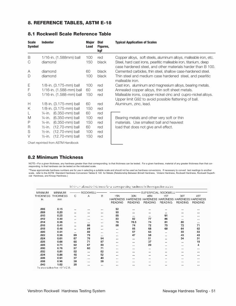
Newage Hardness Testing - 51Versitron Rockwell Hardness Testing System
8. REFERENCE TABLES, ASTM E-18
8.1 Rockwell Scale Reference Table
8.2 Minimum Thickness
Scale Indenter Major Dial Typical Application of ScalesSymbol Load Figures, kgf B 1/16-in. (1.588mm) ball 100 red Copper alloys, soft steels, aluminum alloys, malleable iron, etc. C diamond 150 black Steel, hard cast irons, pearlitic malleable iron, titanium, deep case hardened steel, and other materials harder than B 100.A diamond 60 black Cemented carbides, thin steel, shallow case-hardened steel. D diamond 100 black Thin steel and medium case hardened steel, and pearlitic malleable iron. E 1/8-in. (3.175-mm) ball 100 red Cast iron, aluminum and magnesium alloys, bearing metals. F 1/16-in. (1.588-mm) ball 60 red Annealed copper alloys, thin soft sheet metals. G 1/16-in. (1.588-mm) ball 150 red Malleable irons, copper-nickel-zinc and cupro-nickel alloys. Upper limit G92 to avoid possible flattening of ball. H 1/8-in. (3.175-mm) ball 60 red Aluminum, zinc, lead. K 1/8-in. (3.175-mm) ball 150 red L ¼-in. (6.350-mm) ball 60 red M ¼-in. (6.350-mm) ball 100 red Bearing metals and other very soft or thin P ¼-in. (6.350-mm) ball 150 red materials. Use smallest ball and heaviest R ½-in. (12.70-mm) ball 60 red load that does not give anvil effect. S ½-in. (12.70-mm) ball 100 red V ½-in. (12.70-mm) ball 150 red
Chart reprinted from ASTM Handbook
NOTE—For a given thickness, any hardness greater than that corresponding to that thickness can be tested. For a given hardness, material of any greater thickness than that cor-responding to that hardness can be tested on the indicated scale.
*These approximate hardness numbers are for use in selecting a suitable scale and should not be used as hardness conversions. If necessary to convert test readings to another scale, refer to the ASTM Standard Hardness Conversion Tables E 140 for Metals (Relationship Between Brinell Hardness, Vickers Hardness, Rockwell Hardness, Rockwell Superfi-cial Hardness, and Knoop Hardness.)

52 - Newage Hardness Testing Versitron Rockwell Hardness Testing System
8.3 Round CorrectionCharts reprinted from ASTM Handbook
8.5 Hardness Converson Chart, Low Range

Newage Hardness Testing - 53Versitron Rockwell Hardness Testing System
8.4 Hardness Converson Chart, High Range
The Brinell hardness numbers in boldface type are outside the range recommended for Brinell hardness testing in 3.2.2 of ASTM Method E 10 Test for Brinell Hardness of Metallic Materials. These Scleroscope hardness conversions are based on Vickers-Scleroscope hardness relationships developed from Vickers hardness data provided by the National Bureau of Standards for 13 steel reference blocks. Scleroscope hardness values obtained on these blocks by the Shore Instrument and Mfg. Co. Inc., the Roll Manufacturers Institute, and members of this institute, and also on hardness conversions previously published by the American Society for Metals and the Roll Manufacturers Institute.

54 - Newage Hardness Testing Versitron Rockwell Hardness Testing System

Newage Hardness Testing - 55Versitron Rockwell Hardness Testing System
APPENDIX A: Gooseneck Fixture: Installation and Operation
Remove diamond and indenter shroud from test head.
Remove gooseneck fixture from packing and remove black Allen screw noted as (A).
Pull out the small shaft noted as (B.).
Thread this small shaft into test head with pin wrench. Tighten hand tight.
Position gooseneck fixture over shaft and thread it onto test head surrounding the shaft. Hand tighten the top knurled section (D). DO NOT REPLACE SCREW (A) YET.
Set gooseneck into position of test by loosening lower knurled section (E) and turning gooseneck into desired position.
Tighten knurled section (E).
Thread in diamond indenter to lower portion of gooseneck. Hand tighten with pin wrench.
Position indenter shroud surrounding diamond and hand tighten.
Replace screw (A) but be careful not to move inner section (C) as this might loosen the small shaft (B).Appendix B: Automatic Drive Options: AT130-MT2, AT130-MT3

56 - Newage Hardness Testing Versitron Rockwell Hardness Testing System
Appendix B: Motor Drive Options
AT130-MT2 Electric Motor Drive
This tester uses an electric motor assembly, mounted to the top of the stand, to apply test loads.
After installing the test head, connect the cables from the motor assembly to the back of the tester readout unit. Each connector end is keyed so that only the proper male and female ends will fit.
The test cycle is activated by pressing the “Start” key, “0” on the number section of the keypad or by using the optional foot switch.
If the tester does not cycle properly or does not apply full load, check the positioning of the actuating arm assembly as indicated in the drawings.
CAUTION: DISCONNECT THE TESTER FROM THE POWER SUPPLY BEFORE REMOVING MOTOR COVER.
1-Regulator2-Solenoid3-Air Cylinder4-Exhaust5-Factory Air6-Back Flow Valve7-Top Flow Valve

Newage Hardness Testing - 57Versitron Rockwell Hardness Testing System
AT130- MT3 Pneumatic Drive
This tester uses a pneumatic cylinder to operate the test head. To hookup perform the following steps:
1. Connect shop air to regulator/filter on back of stand.2. Adjust air pressure to 80 p.s.i.3. Air cylinder speed has been pre-set at factory but can be
adjusted to suit particular needs. To change speed of load application, adjust valve screw located through hole on top of cover. To change load release, adjust valve screw located on the back of air cylinder. Turn valve screws clockwise to decrease speed; counterclockwise to increase speed.
If the tester does not perform properly or does not apply full load, perform the following adjustment procedures: CAUTION: WATCH YOUR FINGERS.
1. Remove the cover from the pneumatic drive.2. With a test block clamped between the clamping shield and
the anvil, thread the lever into the top of the lever arm (remove black plastic knob from lever to expose threads) and manually apply full load to the tester.
3. Push lever and feel when the full load starts to be applied (the point after the indenter shroud makes contact with the specimen where there is more resistance to pushing the lever) and when it reaches full load. Release the lever and find the mid point between position 2 and 3. (See drawing on this page.)
4. The bottom of the bearing should be on the same line as the top of the actuator +/- 1/32”.
5. If adjustment is needed to the bearing arm height, remove the bearing to gain access to the bottom adjusting set screw, then remove the first bottom set screw completely.
6. Loosen the two front set screws slightly. The arm is now adjustable up and down by turning the bottom set screw to raise or lower the arm.
7. Tighten front set screws, insert bottom locking set screw, and reinstall the bearing. Recheck the operation and then remove the lever and insert the top set screw.
8. Install the locking cap onto the end of the spline.9. Make a test10. Adjust the speed of the stroke extension to a moderate
setting by adjusting the screw on top of the front flow control valve. Adjust retraction stroke speed by turning the rear flow control valve. The retraction can be set faster than the extension speed.
11. Install the cover over the pneumatic assembly.
1. Bracket2. Air Cylinder Set Screws3. Air Flow Control Fitting4. Regulator6. Solenoid7. Cylinder Shafte. Delrin Deadening Ring9. Actuator Head10. Electronic Board11. Delrin Positioning Bearings12. Motor Lever Arm13. Spline Shaft14. Side Set Screws15. Top Set Screw16. Bottom Set Screw17. Lever Arm Bearing18. Locking Cap
Relative positions of sheath for setting stroke.
1. At rest sheath-to-stand gap2. Start of load sheath-to-stand gap3. Full load sheath-to-stand gap

58 - Newage Hardness Testing Versitron Rockwell Hardness Testing System
APPENDIX C: Automatic Head-Height Adjustment Option
Testers supplied with a motorized head height adjustment option can move the top of the tester and test head up or down automatically to accommodate testing on parts that vary greatly in size.
The control box has 4 controls
1. To turn on, turn arrow knob to brake position, plug in the power cord and flip the ON/OFF toggle switch to ON. The power light will come on.
2. Turn the knob to “Lower” for downward travel, “Raise” for upward travel. Release knob to stop motion.
3. Place specimen on anvil or anvil stage, and practice clamping the specimen and unclamping it. Adjust torque and speed settings to desired levels.
4. Avoid running the height all the way up. If it gets stuck at this position, turn torque to “OFF” and arrow knob to “Forward” to unstick.
CAUTION: The operator must take care not to pinch his hand between test head and specimen or anvil. Serious operator injury may result.

Newage Hardness Testing - 59Versitron Rockwell Hardness Testing System
APPENDIX D: Optional Software Features
Following is a description of the operation for these options:
1. Print Options
In addition to the standard print functions, there may be optional functions installed: X-Bar/R Chart, Verify Chart, or Set Codes.
A. The X-Bar & R Chart prints these two statistical charts (at right) for all the results stored in memory. The X-Bar (average) chart is always printed, while the R (range) chart is printed only if the average mode is in effect. If the results in memory are mixed single readings and averaged readings, the charts will show zero range for the single readings.
B. The Verify Chart prints the history of the verification results of the calibrations run on the tester. The tester stores a maximum of 30 runs, and after the 30th, the oldest one is dropped to make room for the latest one. The “P” or “F” code after the time and the result stands for pass or fail according to ASTM E-18 standards.
C. The Set Codes option allows the operator to enter codes specific to the printer that he is using to print in compressed mode (132 columns on an column printer) and cancel compressed mode. Please refer to the manual of your printer for these codes. (Note: These are used only for chart printing.)
2. Tolerance Options
Under the Tolerance Function, in association with the X-Bar & R chart, there may be selections for XLCL, XUCL and Range UCL. These three values represent the X-Bar Chart Lower Control Limit, the X-Bar Chart Upper Control Limit and the Range Chart Upper Control Limit, respectively. These selections allow the operator to enter predetermined values. The defaults for these values are 0 and 9999 for X-Bar and 0 for Range. If the default values are not entered the software automatically calculates the XLCL and XUCL for the X-Bar chart; if values are entered, those values are used and the calculated ones are ignored.
3. Round Corrections Option
The round correction function is implemented through the 0-Set Key, which is protected by the security code. This function provides automatic compensation for hardness tests taken on small diameter parts, according to the ASTM chart. For each scale there are certain diameters which need round correction. Only these diameter values can be entered; entering a different one produces an error message.
When testing these diameters proceed as follows: Press the 0-Set key, the readout will display:
Diameter?

60 - Newage Hardness Testing Versitron Rockwell Hardness Testing System
This is the prompt to enter the diameter value. The first digit is for inch integers, the other two are for fractions. If the diameter is less than one inch, “0” must be entered for the first digit.
Examples are:1 1/2 for 1½”0 3/4 for ¾”1 0/0 for 1”
After completing the three digits, press the enter key, and the last character on the display will flash off and on to indicate that the round correction is in effect. At this point the tester is ready to test small round parts.
To eliminate the round correction factor, reenter the function and use “0 0/0” for the diameter and press enter. The flashing character will disappear, returning the tester to normal operation.
NOTE: If a printer is being used when the round correction is in effect, the message “Corrected for xxx diameter” will be printed after the value in print result mode and on the header in print totals mode. No message will be printed in print history mode.
4. Scale Selct Option
For version 5.0 and higher (see self test message to determine release number) the scale can also be selected by pressing the Scale Select key followed by the number associated with the desired scale and the Enter key. For example, instead of going through the scales sequentially to display HRC 1, HRB 2, HRA 3, etc.; HRA can be selected by pressing Scale Select, 3, and Enter.
5. Clock Option
This function is accessed through the Mode key. Press “MODE’ and then the “NO” key until the display reads “SET CLOCK?” Press the “YES” key to display the date and time. The blinking digit can be changed at this point. Press the ENTER key to proceed to next digit until all digits have been entered.
Note: The date appears in 24 hour mode, i.e., 5:00 PM = 17:00
6. Split Memory Option
This feature allows the available memory to be divided into 20 separate files (10 for diamond scales, 10 for ball scales) to allow independent data analysis of each file. For instance, multiple HRC scales (files) could be used and named HRC1, HRC2, etc. Each file will have its own tolerances, history, etc. The file name is user defined with up to 5 characters. The percentage of memory per file can also be set.
Press the ‘STAT” key and then the ‘NO” key until the display shows ‘SPLIT MEMORY?” Pressing the “YES’ key will cause the display to read “ENTER CODE”. At this point enter the code for Split Memory. This will clear the history files to allow for reassignment of memory.-The display will now read “HRC1” If you wish to change the heading,

Newage Hardness Testing - 61Versitron Rockwell Hardness Testing System
press the Scale Select button to begin character selection sequence (see section on alpha/numeric characters in these appendices for details). If you wish to use the current heading, press ENTER to proceed.
-The display will read “HRC MEM PCT XX”. The XX is the percentage assigned to this scale by default. The desired percentage can now be entered followed by pressing the ENTER key. The display will go to the next scale until all available scales have been displayed.
NOTE: Care must be taken when assigning percentages not to go over 100% or data will be lost.
The History Function can be turned off so that test results are not stored in memory.
-Press the MODE key, then the NO key, until the display reads DISABLE HISTORY?
-Press the YES key.
-To turn Split Memory back on, repeat the procedure above. The display will read ENABLE HISTORY?, then press YES.

62 - Newage Hardness Testing Versitron Rockwell Hardness Testing System
7. Effective Case Depth Option
Traverses are performed in the Rockwell C scale unless another optional scale has been added. The examples used in this section are for micro hardness loads. Actual spacing of test positions is dependent on test load used.
A. Traverse setup (normal)
1. To move to Traverse Mode, press the MODE key and select X-Y TABLE Function (when the tester is in the standard mode), or whenever the tester is turned on the display will show:
START TRVS?
2. Press the NO key. The display will show:
TRVS SETUP?
3. Press the YES key. The system can store 4 traverse configurations at one time. After the operator presses the YES key the first one appears (if a printer is used it will start to print all test setup inputs at this time).
CONFIG 1?
If the operator presses The YES key to the STANDARD setup, then he will be storing the setup commands in that file. If the operator presses the NO key when the STANDARD setup appears, the remaining setup files will appear in sequence as he presses the NO key.
CONFIG 2? CONFIG 3? CONFIG 4?
If the operator presses the YES key when any of these setup files are on display, the setup commands will be stored in that file. There is no built-in difference between the four setup files except the name. However the operator can make each one perform a different series of traverse tests.
4. For this example, press the YES key to the STANDARD setup. The display will change to read:
CLEAR CONFIG?
This is a precaution so the operator can verify whether he wants to override any setup that may be in the STANDARD file. Also, if the operator wants to view the values of the setup he may press NO, then press the ENTER key to all values and NO to prompts where values are not entered.
5. Press the YES key for this example if the operator is sure that there is no important setup already in the file. The display will change to read:
EDGE OFFSET?
6. In this example we will instruct the operator to setup a straight

Newage Hardness Testing - 63Versitron Rockwell Hardness Testing System
traverse with one row of test positions, each .010” apart. (See at right.)
This prompt for edge offset asks how far from the edge of the specimen the first test should be taken in increments of one thousandth. Enter the number 10 (for .010”) and press the ENTER key. The display will charge to read:
X-SPACING?
7. Key in “10” followed by the ENTER key to position each test .010” apart. (It is important to keep the test impressions at least .005” apart. If closer spacing is desired, see section for TRAVERSE SETUP Shallow Case. The display will change to read:
HOW MANY?
8. Enter 9 followed by the ENTER key to select 9 tests after the first one for a total of 10 tests. (It’s easy to calculate the total traverse distance would be .100’) The display will then change to read:
X-SPACING?
9. This prompt allows the operator to change the distance between test points, if, for instance, he wanted to run a traverse into the core region. For this example press the NO key. The display will change to read:
Y-SPACING?
11. This prompt would allow the operator to run a parallel row of impressions to the first. This is useful for running a shallow case traverse. For this example press the NO key. The display will change to read:
HRC READY?
At this point the tester is ready to operate in standard, non-traverse mode. To operate the traverse that was just setup, see next section.
B. Traverse Operation (Normal)
1. To run a traverse that has previously been setup in the SETUP procedure, press the MODE key. If a printer is used it will start to print screen displays. The display will show:
HRC START TRVS?
2. Press the YES key. The display will change to read:
HRD CONFIG 1?
3. There are 4 setup files: CONFIG 1 through 4. If the operator presses NO to “CONFIG 1” the other setups will appear in sequence as he repeatedly presses the NO key. If the operator is running the setup that was presented as an example in the

64 - Newage Hardness Testing Versitron Rockwell Hardness Testing System
previous section, press the YES key when the display prompts for “CONFIG 1”. The display will change to read:
DELETE GRAPH?
4. This prompt reminds the operator that he may want a printout of the last traverse results that were run, if he has not already printed them. If the operator presses the YES key, all the results will be erased from memory and the tester will be able to run another traverse. (Otherwise, press the NO key and then the PRINT key to obtain a printout.) For this example press the YES key. The display will change to read:
EDGE = 10
5. Pull the slide table back to the scope position and mount the specimen in the self-leveling anvil stage. Using the micrometers, position the edge of the specimen so that the edge runs from side to side with the specimen surface at the bottom half of the monitor. Make sure the crosshairs fall at the very edge of the specimen. (This orientation of the specimen is used for sake of the example. The specimen may be positioned with the test surface at any right angle.
6. Press the zero buttons on the micrometers to zero the displays.
7. Turn the “X” micrometer (on the side of the positioning table- not the front) clockwise until the display reads “-.0100”. Make certain the specimen in the scope is moved so the crosshair is at the first position to be tested.
8. Push the slide table so the specimen is located under the indenters.
9. Press the start pedal. Hold the pedal down until the test result appears on the display, such as:
A1: HRC 60.5
If tolerances are used there will also be a tolerance indication or, the display.
10. After the display shows the test result for a second, it will change to show the next test position such as:
A2 X = 20
11. Turn the ‘X’ (side) micrometer till it reads .0200. Then press the start button or pedal.
12. Repeat this procedure for taking tests until the display reads:
TEST COMPLETE
This display remains on view for a few seconds then changes to read:PRINT GRAPH?

Newage Hardness Testing - 65Versitron Rockwell Hardness Testing System
NOTE: If the specimen does not go above HRC 50 or fall below HRC 50 the display will read ‘DEPTH INVALID”. If the operator still desires a graph, press YES two times.
13. Press the YES key to get a case depth graph. The effective case depth is printed at the bottom. Press the NO key to view the case depth and return to the ready status. If the case depth is “invalid’, press the YES key to print the graph.
14. After the graph is printed the operator has the opportunity to print the data out again in sequential order along with the distance from the edge of the specimen. The prompt for this function is “PRINT TESTS?”. This function is primarily available for shallow case traverses. See next section.
NOTE: At any time the traverse can be ended by pressing the NO key.
C) Traverse Setup (Shallow Case)
If test impressions need to be spaced more closely than the minimum distance between indents (three times the diameter of the indentation - in this example 0.010” apart) the operator should stagger the test positions laterally so that they are far enough apart but still progress from the surface at a closer spacing. The following sample shows a shallow case traverse starting at .008” from the specimen edge (operator must allow a minimum distance from the edge to be 2.5 times the diameter of the indentation) while testing at .001” increments relative to the edge of the specimen and a total of .021” from the edge, then progressing for 3 tests at .010” spacing to check the core hardness. The beginning 7 tests are numbered. If the operator plans to setup his own procedure, it might be helpful to draw it out as in the example shown.
START SETUP
1. Press the MODE key then the NO key twice. The display will read:
HRC CONFIG 2?
2. Press the YES key twice to select the CONFIG 2 setup and clear the old setup. The display will read:
EDGE OFFSET?
3. The program is designed to enter one row of tests at a time. Enter 4 then press ENTER key to designate the position of the first test. The display will change to read:
X-SPACING
4. Enter 10 (for .010” offset between tests), then press the ENTER key. The display will charge to read: X Axis
1
2
3
4
5
6
7

66 - Newage Hardness Testing Versitron Rockwell Hardness Testing System
HOW MANY?
5. Press 3 followed by the ENTER key to indicate 3 tests will be performed after the first one. The display will change to read:
X-SPACING
START ROW 2
6. Press NO key to indicate that is all the tests to be setup in that row. The display will read:
Y-SPACING?
7. Select “10” then the ENTER key to start the second row of tests .010” over from the first row. The display will change to:
EDGE OFFSET?
8. Press “9” then the ENTER key. Each test in this row of tests will be 0.009 from the edge and .001” further from the edge than the first row.
9. As you can see, all the displays and operator inputs are being printed as they appear and are entered. To finish the example shallow case traverse, here is a printout showing the displays and answers to create the desired setup. Follow it through to create the desired sample traverse procedure. Your printout should match the sample below!
Also Note: The 3rd row requires a charge of X-SPACING for 3 tests after the first set of tests are taken. (This could also be done by simply entering “8” to the question HOW MANY since the spacing did not actually change.)
D. Traverse Operation (Shallow Case)
1. If the operator has followed the previous example for traverse setup on a shallow case, he should select the same file from the “START TRVS” prompt. (If the operator has not first read the manual for Traverse Operation, Normal, he should do so first.) Otherwise select the file that contains the shallow case traverse program.
2. Just as in the normal traverse operation, the operator will perform one row of tests at a time. (Note: The operator does not test in a staggered fashion for each test that is .001” farther off the surface than the previous position. Since each row is performed sequentially, the operator has to only adjust one micrometer at a time. This allows less possibility of operator error and increases his speed.)
3. Perform the first row of tests. After the last test in the row is complete, the display will read:
RETURN TO X = 0

Newage Hardness Testing - 67Versitron Rockwell Hardness Testing System
The operator must press the YES key to verify he has moved back to the edge of the specimen. The display will read:
X = 10, Y = 10
4. The operator must adjust both micrometers to read .0100”’ then make a test. (Note: the printout identifies the second column of test results with a “B”.) Each succeeding test is done in the normal fashion until the third row is reached where the same procedure is repeated.
5. After all testing is complete and the operator chooses to print the graph, the tests will be plotted in correct sequence according to their distance from the specimen edge.

68 - Newage Hardness Testing Versitron Rockwell Hardness Testing System

Newage Hardness Testing - 69Versitron Rockwell Hardness Testing System
8. Alpha-Numeric Characters for Lot Number/Split Memory Option
The alphanumeric characters allow the selection of letters and/or numbers as well as the hyphen, “-”, period “.”, slash “/” or blank spaces in printouts of lot numbers and user assignable headings in split memory.
To select a numeric character, press the desired number on the keypad. It will be automatically locked in so the operator can pro-ceed to the next character.
To select an alpha or miscellaneous character, press the “Select” key to scroll through the alphabet including the special charac-ters. Press the NO key to scroll through the characters in reverse. Note: a blank space appears before the letter “A”.
Press the YES key to lock-in your selection and proceed to the next character. Press the CONV key to delete the last selection. Press the ENTER key to end the sequence and return to the test mode.

70 - Newage Hardness Testing Versitron Rockwell Hardness Testing System
APPENDIX E: Calibration & Service Support
Newage Testing Instrument’s sales and service staff and our associates have the capability to support hardness testing needs anywhere in the world. Additionally, Newage Versitron® test heads can be shipped to our Pennsylvania location for factory service.
We provide a loaner/rental program for some models (subject to availability) to keep our customers in operation while their test heads are serviced.
For details call 800-806-3924 (or 215-355-6900 in Pennsylvania and outside the US).
Here is what you can expect from the Newage
ServiceNetwork:
• For emergency service, you’ll receive a fast, on-site response by a qualified technician.
• Standardized procedures with detailed documentation that will pass your internal and external audits.
• Verification, calibration, preventive maintenance, and repairs on many different types of hardness testing systems,
regardless of make and model. Newage stocks commonly used spare parts for testers from other manufacturers.
• All vehicles and service personnel are fully insured for liability for on-site service at your facility.
• Call 800-317-1976 to schedule on-site service of your hardness tester.
• Call 800-806-3924 to get answers to questions in any area of hardness testing, or receive engineering assistance on any hard-ness testing application. (Call 215-355-6900 in Pennsylvania or outside the US)
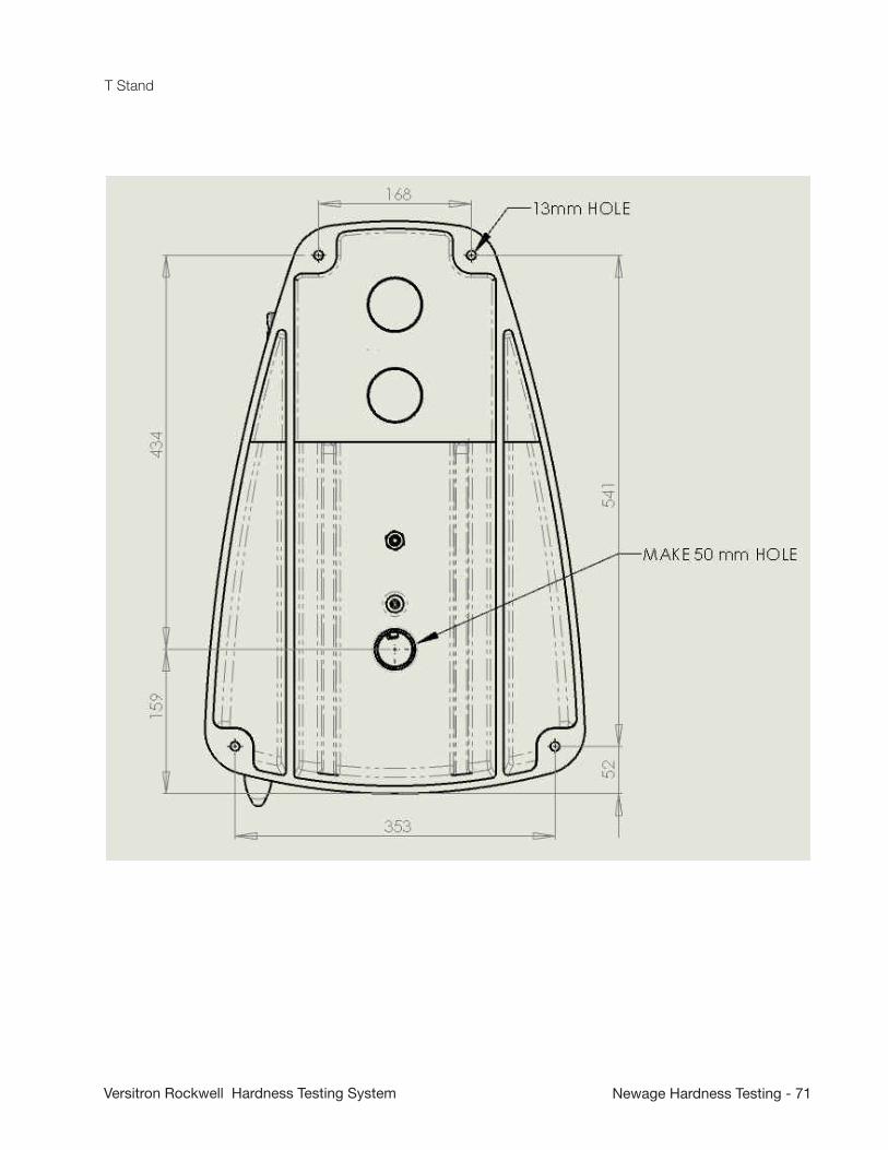
Newage Hardness Testing - 71Versitron Rockwell Hardness Testing System
T Stand

72 - Newage Hardness Testing Versitron Rockwell Hardness Testing System
N Stand

Newage Hardness Testing - 73Versitron Rockwell Hardness Testing System
ONE YEAR LIMITED WARRANTY
Should Newage Testing Instruments, Inc. equipment require service, we will repair or replace, at our option, any part or product which upon examination by a NewAge service
technician, shows to be defective in material or workmanship. Excluded from this warranty are any parts that are to be replaced as part of normal prod-
uct operation, such as indenters, test blocks, and indenter shrouds.
This warranty is extended to the original purchaser only, for a period of one year (12 months) from owners date of purchase.
This warranty IS NOT VALID IF THE INSTRUMENT HAS BEEN MODIFIED, MISUSED OR DAMAGED in any way. This includes damage caused by dis-assembly by any person other than an authorized Newage Testing Instruments’ service
technician.
Please read all operating instructions according to the manual supplied with the instrument prior to operation. This warranty applies only to instruments sold by
Newage Testing Instruments, Inc. and its authorized distributors.
Newage Testing Instruments, Inc.. is not responsible in any way for losses, damage, or other form of consequential damage resulting from equipment failure
or improper use.
IMPORTANT: Register your instrument with Newage Testing Instruments, Inc. service department by filling out and returning the enclosed warranty registration card

www.hardnesstesters.com
Information in this document is subject to change without notice. ©2011 by AMETEK, Inc., www.ametek.com. All rights reserved.
Newage Testing Instruments, Inc.
820 Pennsylvania Blvd • Feasterville • PA 19053 • USA
Tel: 215-355-6900 • Fax: 215-354-1803
AMETEK Denmark (Scandinavia)Tel +45 4816 8000 • [email protected]
Lloyd Instruments Ltd. (UK)Tel +44 (0) 1243 833 370 • [email protected]
AMETEK SAS (France)Tel +33 (0) 1 30 68 89 40 • [email protected]
AMETEK Europe GmbH (Germany)Tel +49 0 2159 9136 70 • [email protected]
AMETEK Singapore Pvt. Ltd. (Singapore)Tel +65 484 2388 • [email protected]