vertical floor consoles by first co. - buyac.com series vertical console fan coils 300-1200 cfm...
TRANSCRIPT

ProductSpecifications
FIRST OPERATIONS, LP - P.O. Box 270969 - Dallas, Texas 75227 - Ph. (214) 388-5751 - Fax (214) 388-2255 - www.firstco.com
VFB SeriesVSB SeriesVCB Series
Vertical ConsoleFan Coils
300-1200 CFM
Vertical Floor ConsolesBy First Co.
VFB Series (flat top) VSB Series (slope top) VCB Series (concealed)
• Heavy, 18 Gauge Embossed Cabinets
• Stamped Louver Discharge Grills
• Service Switch
• Dependable Lead Times
• Competitively Priced
• Easily Serviced
• Quiet Operation
• Attractive Appearance
• Compact Design
• Durable Construction
VSB Serieswith valve package
(front panel removed)
VSB Series(slope top)
NOW W
ITH 18
GAUGE C
ABINET
AND FACTO
RY
INSTA
LLED SERVIC
E SW
ITCH
®

CFM (100'S)3,4,6,8,10,12
Unit StyleVCB - ConcealedVSB - Cabinet slope topVFB - Cabinet flat top
Vintage
Unit Voltage126 - 120V-1PH-60Hz246 - 208/240V-1PH-60Hz225 - 220V-1PH-50Hz276 - 277V-1PH-60Hz
Coil Type3 - 3 row4 - 4 row31 - 3 row cool, 1 row heat41 - 4 row cool, 1 row heat (available on 300-800 CFM only)
Coil ConnectionR - Right Hand (Facing Unit Front)L - Left Hand
Valve Package(Contact factory for options)
Model Number Nomenclature
- 2 -
12 VC B 0 - 126 - 31 R - 2B - N1
Table of Contents
Model Number Nomenclature ...................................2
Features / Benefits ...................................................3
Control Options .........................................................4
Unit Selection ...........................................................5
Air Volume Capacity .................................................6
Motor Data ................................................................6
ARI Standard Ratings ...............................................7
Thermostat Options(see Page 4)
NC = No Controls
Water Heating Ratings .............................................7
Dimensional Data VCB Series ........................................................9 VSB Series .......................................................10 VFB Series .......................................................11
Guide Specifications ...............................................12

Cabinets All cabinets are constructed of heavy 18 gauge embossed galvanized steel to resist corrosion. Series VSB and Series VFB models are finished with an elec-trostatically applied, baked-on powder coating. The finish is an attractive light gray color. Wrap-around cabinet can be quickly and easily removed for service without the use of tools. Heavy duty "Stamped" Louver Grilles are standard.
Coils Coils are available in standard and high capacity configuration and all include manual air vents. Coils are constructed of seamless copper tubing expanded to high efficiency aluminum fins to assure maximum heat transfer. Each coil is factory tested to 350 psig.
Drain Pans The primary drain pan is constructed of galvanized steel and coated to resist corrosion. This pan extends under the entire coil and coil headers. An injection molded secondary drain pan provides complete con-densate drainage from the primary pan and is located under the valve package (if provided). Secondary drain pan can be rotated 180 degrees to allow field piping to enter the unit from different locations.
Motors Standard motors are 120V, three speed (1), PSC type with internal thermal overload protection. Motors have permanently lubricated sleeve bearings for long life. All motors are resiliently mounted with rubber bushings to assure quiet, vibration-free operation and are easily removed.(1) The size 3 motor (model 3VFB/VSB/VCB) may not start on low speed due to low starting torque. These units must be wired to start on either Medium or High speed.
Features / Benefits
- 3 -
Vertical Floor Consoles . . . By First Co.Quiet, Attractive, Versatile
First Co.'s "V" series vertical floor consoles are slim and extremely attractive. Their pleasing appearance allows them to blend with any decor. These products are engineered to be quiet and designed to be easy to install and service. These units are ideal for perimeter heating and cooling in hotels, apartments, hospitals, public office buildings, offices, corridors, and other multi-room build-ings.
Three models are available to meet any application: recessed, flat top console, and slope top console. They are available in 6 sizes with airflow from 300 through 1200 CFM to supply just the right amount of air. Available coils include 3 and 4 rows for 2-pipe systems, and 31, 41 (300-800 CFM only) split coils for 4-pipe systems.
Blower Assemblies All blower wheels are centrifugal, forward curved, and dynamically balanced for smooth, quiet opera-tion. Blower assemblies can be easily removed for service.
Discharge Grille The Series VFB and Series VSB models are fur-nished standard with a heavy-duty, 18 gauge stamped louver grille.
Filters A 1/2 inch permanent filter is provided as standard on all units. The filter is easily removed from the front of the unit without tools.
Electrical All electrical components are factory routed to a single electrical compartment on each unit. All field wiring connections are made at this electrical compartment. Electrical Service Switch is standard on ALL models.
Options A wide variety of two and four-pipe control systems are available with unit mounted or remote thermostats. Standard options include valve cycle control systems. Other options include three speed switches, vari-ous motor voltages, and manual or motorized fresh air damper. See "Model Number Nomenclature" on Page 2 for unit options and Page 4 for control options.Fresh air wall box is fabricated of aluminum with drain holes and a double set of louvers in series to prevent moisture draw through.
- 4 -
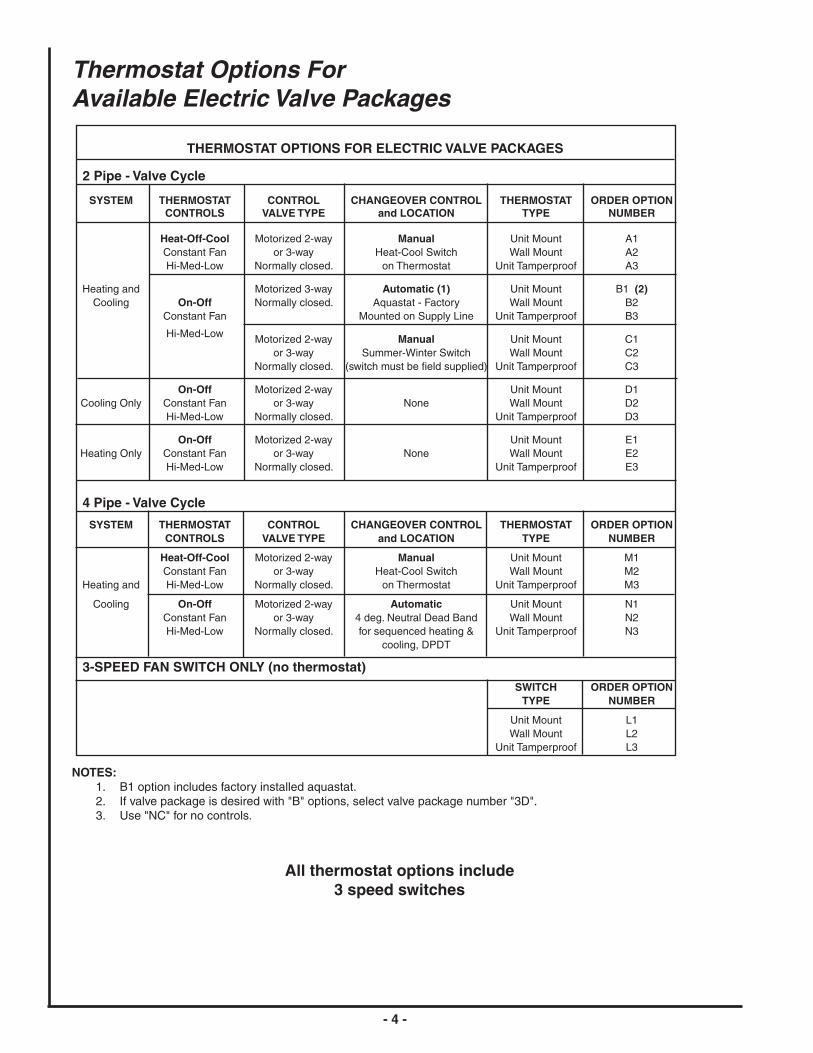
Thermostat Options ForAvailable Electric Valve Packages
NOTES: 1. B1 option includes factory installed aquastat. 2. If valve package is desired with "B" options, select valve package number "3D". 3. Use "NC" for no controls.
All thermostat options include3 speed switches
THERMOSTAT OPTIONS FOR ELECTRIC VALVE PACKAGES
2 Pipe - Valve Cycle
SYSTEM THERMOSTAT CONTROL CHANGEOVER CONTROL THERMOSTAT ORDER OPTION CONTROLS VALVE TYPE and LOCATION TYPE NUMBER
Heat-Off-Cool Motorized 2-way Manual Unit Mount A1 Constant Fan or 3-way Heat-Cool Switch Wall Mount A2 Hi-Med-Low Normally closed. on Thermostat Unit Tamperproof A3
Heating and Motorized 3-way Automatic (1) Unit Mount B1 (2) Cooling On-Off Normally closed. Aquastat - Factory Wall Mount B2 Constant Fan Mounted on Supply Line Unit Tamperproof B3
Hi-Med-Low Motorized 2-way Manual Unit Mount C1 or 3-way Summer-Winter Switch Wall Mount C2 Normally closed. (switch must be field supplied) Unit Tamperproof C3
On-Off Motorized 2-way Unit Mount D1 Cooling Only Constant Fan or 3-way None Wall Mount D2 Hi-Med-Low Normally closed. Unit Tamperproof D3
On-Off Motorized 2-way Unit Mount E1 Heating Only Constant Fan or 3-way None Wall Mount E2 Hi-Med-Low Normally closed. Unit Tamperproof E3
4 Pipe - Valve Cycle
SYSTEM THERMOSTAT CONTROL CHANGEOVER CONTROL THERMOSTAT ORDER OPTION CONTROLS VALVE TYPE and LOCATION TYPE NUMBER
Heat-Off-Cool Motorized 2-way Manual Unit Mount M1 Constant Fan or 3-way Heat-Cool Switch Wall Mount M2 Heating and Hi-Med-Low Normally closed. on Thermostat Unit Tamperproof M3
Cooling On-Off Motorized 2-way Automatic Unit Mount N1 Constant Fan or 3-way 4 deg. Neutral Dead Band Wall Mount N2 Hi-Med-Low Normally closed. for sequenced heating & Unit Tamperproof N3 cooling, DPDT
3-SPEED FAN SWITCH ONLY (no thermostat) SWITCH ORDER OPTION TYPE NUMBER
Unit Mount L1 Wall Mount L2 Unit Tamperproof L3

- 5 -
Selection of Unit Type
General The achievement of an efficient fan-coil system is dependent upon accurate system design and proper equipment selection. Variations, limitations and control of fan-coil systems, design conditions and design load calculations are not described in detail in this catalog. More detailed information may be found in the ASHRAE Guide. The mechanical system designer must select the unit types best suited to the overall system before the actual unit sizes can be determined. The factors that generally influence this decision are intended build-ing usage, building layout, architectural and aesthetic values, economics, geographical location, and type of maintenance service available. The general results may be a mixture of various unit types within a given system. First Co. manufactures a fan-coil unit to meet your every need.
Basic Design Data Prior to selecting the individual unit sizes, the design engineer must fix or determine the following factors: 1. Inside and outside wet and dry bulb design temperatures. 2. Method of introducing the ventilation air. 3. Wet and dry bulb temperatures of the air mix-ture entering the unit coil. 4. Total and sensible heat gains and losses of the area to be served. 5. Properties of the heating and cooling medium. 6. Available electric power service. 7. Any special design requirements of the build-ing or system.
Selection of Unit Size The capacity ratings presented in this catalog are provided for initial unit selection only. Unit size selec-tion should be determined by using First Co.'s fan-coil selection computer program. Water cooling and heat-ing capacities, unit air flow, and static pressure are all incorporated into the program to provide the best pos-sible selection. Consult your First Co. representative for a selection tailored to your application. Unit sizes for the ideal system should be selected by calculating the peak load requirements due to unusu-ally high occupancy or severe climatic conditions and with fan operating at high speed. Ordinary day to day cooling and heating requirements are then achieved at
Unit Selection
low and medium speeds. Ventilation requirements should be considered along with heating and cooling capacity to determine the proper unit size. Outside fresh air must be tempered before entering the unit if freezing conditions are expected.
Cooling Coil Requirements Having checked the minimum unit size to meet the ventilation requirement, the unit size is generally selected on the basis of matching the sensible cooling capacity of the unit with the calculated requirements when operating at high speed.
Coil Types Standard and high capacity coil types are available for all models. • Standard coils are designed to meet both the cooling and heating requirements in a typical system. • High capacity coils are designed to meet cool-ing and heating loads that exceed typical system requirements for ceiling units.
Heating Requirements Heating requirements for two-pipe systems are generally met by employing the same water flow rate as cooling and adjusting the entering hot water temperature to obtain a matching unit heat output at low fan speed. Four-pipe systems are generally designed by specify-ing the flow rate through the separate heating coil to meet the required heat load with the fan operating at low speed.
In keeping with its policy of continuous progress and product improvement, First Operations reserves the right to make
changes without notice. Maintenance for all First Co. products is available under "Product Maintenance" at www.firstco.com.

Notes: 1. Values are standard CFM at sea level, 70 degree EAT. with dry coil. 2. E.S.P. - inches water. 3. Values include filter and / or grille where applicable.
- 6 -
Motor / Blower Performance
Notes: * Total unit motor amps and watts shown for 2 motors. (Unit size 10 and 12)
BSV,BFV,BCV/yticapaCemuloVriA
TINU.P.S.E0.0@MFCDEEPSNAFROF
DETACIDNI
DEEPSHGIH.P.S.E@MFC
DETACIDNI
LEDOM EZIS HGIH DEM WOL 50.0 01.0 51.0 02.0
BCV
BFV
BSV
3 082 542 012 552 032 502 571
4 004 023 022 073 033 092 042
6 006 034 023 075 045 015 084
8 008 086 085 067 037 007 066
01 0001 088 076 079 029 088 038
21 0221 0301 087 0711 0211 0701 0201
/ataDrotoM BSV,BFV,BCV
ROTOMDEEPS
EZISTINU
3 4 6 8 *01 *21
PHLANIMON02/1
PHLANIMON21/1
PHLANIMON8/1
PHLANIMON6/1
PHLANIMON)2(8/1
PHLANIMON)2(6/1
spmA sttaW spmA sttaW spmA sttaW spmA sttaW spmA sttaW spmA sttaW
ROTOMCSPzH06-HP1-TLOV021
HGIH 08. 59. 0.1 50.1 8.1 002 2.2 052 0.3 053 6.4 025
MUIDEM 54. 06 06. 07 1.1 041 0.2 012 4.2 572 0.3 033
WOL 04. 05 54. 55 08. 09 6.1 071 8.1 012 1.2 032
ROTOMCSPzH05-HP1-TLOV022
HGIH
MUIDEM EMITSIHTTAELBALIAVAATADON
WOL
ROTOMCSPzH06-HP1-TLOV772
HGIH
MUIDEM EMITSIHTTAELBALIAVAATADON
WOL

- 7 -
Standard Coil - Water Heating CapacityRatings - VCB, VFB, VSB (3 row)
High Capacity Coil - Water Heating CapacityRatings - VCB, VFB, VSB (4 row)
Heating Coil Ratings
Notes:1. Rated in accordance with ARI Standard 440. Cooling capacities based on 80 deg. DB / 67 deg. WB entering air, 45
deg. entering water, 10 deg. water temperature rise and high fan speed with standard 120V/1PH/60Hz motor.2. For cooling coil capacities at conditions other than listed, refer to application guide . . . . . . or consult your First Co.
Representative.
Standard Coil - Water Cooling CapacityRatings - VCB, VFB, VSB (3 row)
High Capacity Coil - Water Cooling CapacityRatings - VCB, VFB, VSB (4 row)
Cooling Coil Ratings
TINUEZIS
YTICAPACGNILOOCMPG
RETAW.D.P).rtW.tF(
TINUEZIS
YTICAPACGNILOOCMPG
RETAW.D.P).rtW.tF(
LATOTHUTB
ELBISNESHUTB
LATOTHUTB
ELBISNESHUTB
3 000,8 001,6 6.1 5.4 3 002,9 007,6 8.1 4.5
4 000,21 000,9 4.2 3.9 4 009,31 ,009,9 8.2 9.41
6 000,71 009,21 4.3 3.8 6 000,91 000,41 8.3 8.11
8 ,009,12 008,61 4.4 6.8 8 004,52 007,81 1.5 8.31
01 006,72 005,22 5.5 3.9 01 004,03 007,32 1.6 5.9
21 005,43 005,72 9.6 1.51 21 002,83 001,92 6.7 1.41
TINUEZIS
GNITAEHYTICAPAC
HUTBMPG
RETAW.D.P).rtW.tF(
TINUEZIS
GNITAEHYTICAPAC
HUTBMPG
RETAW.D.P).rtW.tF(
3 005,32 6.1 5.4 3 002,52 7.1 8.4
4 002,43 3.2 6.8 4 006,63 4.2 3.11
6 004,94 3.3 8.7 6 005,25 5.3 2.01
8 005,46 3.4 2.8 8 005,96 6.4 5.11
01 000,78 8.5 4.01 01 002,29 1.6 5.9
21 003,601 1.7 9.51 21 000,311 5.7 7.31
TINUEZIS
GNITAEHYTICAPAC
HUTBMPG
RETAW.D.P).rtW.tF(
3 004,21 8.0 4.2
4 002,81 2.1 1.6
6 000,62 7.1 7.21
8 007,33 2.2 7.22
01 006,33 2.2 9.5
21 002,14 7.2 8.8
1-Row Coil - Water Heating CapacityRatings - VCB, VFB, VSB
Notes: 1. Heating coils rated at 70 deg. DB entering air, 180 deg. entering water, 30 deg. water temperature drop and high fan speed with standard 120V/1PH/60Hz motor. 2. For heating capacities at conditions other than listed, consult your First Co. Representative or the factory.

- 8 -
Fresh Air Wall Box
NOTE: Outside fresh air must be tempered before entering the unit if freezing conditions are expected.
UNIT SIZES 10 & 12Require two fresh air wall boxes.
Motorized Air Damper
# 919-9For sizes 3 through 8
# 919-10For sizes 10 and 12
Shipping Weights
Note:1. Approximate shipping weights do not include valve packages, hot water coils, electric heaters, or other options.
Approximate shipping weights (lbs.)
TINUEPYT
EZISTINU
3 4 6 8 01 21
BCV 55 07 08 59 511 031
BSV/BFV 58 79 011 521 541 561

PR
OD
UC
T D
RA
WIN
GFA
N C
OIL
UN
ITS
MO
DE
L V
CB
N
OT
FO
R C
ON
ST
RU
CT
ION
- 9 -
NO
TE
S:
1) A
LL D
IME
NS
ION
S IN
INC
HE
S.
2) C
OIL
CO
NN
EC
TIO
N T
OLE
RA
NC
E ±
1/4
”3)
HA
ND
OF
UN
IT D
ET
ER
MIN
ED
BY
CO
OLI
NG
C
OIL
CO
NN
EC
TIO
N W
HE
N F
AC
ING
TH
E
FR
ON
T O
F U
NIT
.
10-12V 3-8V
Quo
te D
ate:
Rev
. Dat
e:F
orm
No.
:D
wg.
Lev
.:D
wg.
Sca
le:
NT
S
Sol
d To
:C
ust P
urch
Ord
er #
:C
ontr
act #
:
Pro
ject
Nam
e:Lo
catio
n:E
ngin
eer:
Con
trac
tor:
For
: R
EF
ER
EN
CE
SN
OIS
NE
MID
LA
RE
NE
G
LE
DO
MA
BC
DE
EZI
SN
NO
CLI
OC
GNI
LO
OC
GNI
TA
EH
BC
V3
2/1-7281
2/1-522/1-62
4/3-32
.D.
O8/5
TAE
WS
.D.
O8/5
TAE
WS
BC
V4
2/1-5362
2/1-332/1-43
4/3-13
BC
V6
2/1-3443
2/1-142/1-24
4/3-93
BC
V8
2/1-1524
2/1-942/1-05
4/3-74
BC
V01
2/1-9505
2/1-752/1-85
4/3-55
BC
V21
2/1-7685
2/1-562/1-66
4/3-36
SN
OIT
AC
OL
RE
DA
EH
BC
VS
NOI
TA
CO
LR
ED
AE
HB
CV
DN
AH
TF
EL
1X
1Y
2X
2Y
3X
3Y
4X
4Y
DN
AH
TH
GIR
1X
1Y
2X
2Y
3X
3Y
4X
4Y
WO
R3
57.431.81
00.305.71
--
--
--
--
--
--
WO
R3
57.431.81
00.305.71
--
--
--
--
--
--
WO
R4
05.505.81
00.305.71
--
--
--
--
--
--
WO
R4
5.505.81
00.305.71
--
--
--
--
--
--
WO
R1/3
36.431.81
31.305.71
00.731.51
31.405.12
WO
R1/3
36.431.81
31.305.71
88.605.51
88.305.12
WO
R2/3
36.431.81
31.305.71
00.731.51
88.488.12
WO
R2/3
36.431.81
31.305.71
36.788.51
88.388.12
WO
R1/4
05.505.81
31.305.71
36.700.61
36.452.22
WO
R1/4
05.505.81
31.305.71
57.705.51
88.488.12
WO
R3
52.531.81
52.352.71
--
--
--
--
--
--
WO
R3
52.531.81
52.352.71
--
--
--
--
--
--
WO
R4
52.605.81
52.352.71
--
--
--
--
--
--
WO
R4
52.605.81
52.352.71
--
--
--
--
--
--
WO
R1/3
83.531.81
52.352.71
36.705.51
00.531.12
WO
R1/3
83.531.81
52.352.71
83.700.61
57.457.12
10-12V 3-8V
(LE
FT
HA
ND
UN
IT S
HO
WN
)
®
(RIG
HT
HA
ND
UN
IT S
HO
WN
)

PR
OD
UC
T D
RA
WIN
GFA
N C
OIL U
NIT
SM
OD
EL V
SB
N
OT
FO
R C
ON
ST
RU
CT
ION
- 10 -
NO
TE
S:
1) ALL D
IME
NS
ION
S IN
INC
HE
S.
2) ALL D
IME
NS
ION
S ±
1/4”.3) C
AB
INE
T TO
LER
AN
CE
± 1/16”.
4) 24” CLE
AR
AN
CE
IN F
RO
NT
OF
TH
E U
NIT
IS
RE
QU
IRE
D F
OR
SE
RV
ICE
.3) H
AN
D O
F U
NIT
DE
TE
RM
INE
D B
Y C
OO
L-IN
G C
OIL C
ON
NE
CT
ION
WH
EN
FAC
ING
T
HE
FR
ON
T O
F U
NIT.
6) CO
IL CO
NN
EC
TIO
N TO
LER
AN
CE
± 1/4”.
FR
ES
H A
IR IN
TAK
E
S
IZE
C
OIL
CO
NN
EC
TIO
N
M
OD
EL
A
C
OO
LIN
G
HE
AT
ING
3 V
SB
43
4 V
SB
9 51
6 V
SB
59
5/8" O.D
. 5/8" O
.D.
8 V
SB
67
SW
EAT
S
WE
AT
10 V
SB
75
12 V
SB
83
GE
NE
RA
L D
IME
NS
ION
SN
OT
E: O
utside fresh air must be tem
pered before entering the unit if freezing conditions are expected.
VS
B H
EA
DE
R L
OC
AT
ION
S R
IGH
T H
AN
D
X1
Y1
X2
Y2
X3
Y3
X4
Y4
3 R
OW
4.75
18.13 3.00
17.50 N
/A
N/A
N
/A
N/A
4 R
OW
5.50
18.50 3.00
17.50 N
/A
N/A
N
/A
N/A
3/1 R
OW
4.63
18.13 3.13
17.50 6.88
15.50 3.88
21.50
3/2 RO
W
4.75 18.13
3.13 17.50
7.63 15.88
3.88 21.88
4/1 R
OW
5.50
18.50 3.13
17.50 7.75
15.50 4.88
21.88
3 R
OW
5.25
18.13 3.25
17.25 N
/A
N/A
N
/A
N/A
4 R
OW
6.25
18.50 3.25
17.25 N
/A
N/A
N
/A
N/A
3/1 R
OW
5.25
18.13 3.25
17.25 7.38
16.00 4.75
21.75
VS
B H
EA
DE
R L
OC
AT
ION
S
LE
FT
HA
ND
X
1 Y
1 X
2 Y
2 X
3 Y
3 X
4 Y
4
3 R
OW
4.75
18.13 3.00
17.50 N
/A
N/A
N
/A
N/A
4 R
OW
5.50
18.50 3.00
17.50 N
/A
N/A
N
/A
N/A
3/1 R
OW
4.63
18.13 3.13
17.50 7.00
15.13 4.13
21.50
3/2 RO
W
4.63 18.13
3.13 17.50
7.00 15.13
4.88 21.88
4/1 R
OW
5.50
18.50 3.13
17.50 7.63
16.00 4.63
22.25
3 R
OW
5.25
18.13 3.25
17.25 N
/A
N/A
N
/A
N/A
4 R
OW
6.25
18.50 3.25
17.25 N
/A
N/A
N
/A
N/A
3/1 R
OW
5.38
18.13 3.25
17.25 7.63
15.50 5.00
21.13
10-12V 3-8V
10-12V 3-8V
Quote D
ate:R
ev. Date:
Form
No.:
Dw
g. Lev.:D
wg. S
cale: NT
S
Sold To:
Cust P
urch Order #:
Contract #:
Project N
ame:
Location:E
ngineer:C
ontractor:F
or: RE
FE
RE
NC
E
®
(LEF
T H
AN
D U
NIT
SH
OW
N)

PR
OD
UC
T D
RA
WIN
GFA
N C
OIL
UN
ITS
MO
DE
L V
FB
NO
T F
OR
CO
NS
TR
UC
TIO
N
- 11 -
S
IZE
C
OIL
CO
NN
EC
TIO
N
M
OD
EL
A
C
OO
LIN
G
HE
AT
ING
3
VF
B
43
4
VF
B
51
6
VF
B
59
5/8"
O.D
. 5/
8" O
.D.
8
VF
B
67
SW
EAT
S
WE
AT
10
VF
B
75
12
VF
B
83
NO
TE
S:
1) A
LL D
IME
NS
ION
S IN
INC
HE
S.
2) A
LL D
IME
NS
ION
S ±
1/4
”.3)
CA
BIN
ET
TO
LER
AN
CE
± 1
/16”
.4)
24”
CLE
AR
AN
CE
IN F
RO
NT
OF
TH
E U
NIT
IS
RE
QU
IRE
D F
OR
SE
RV
ICE
.5)
HA
ND
OF
UN
IT D
ET
ER
MIN
ED
BY
CO
OL -
ING
CO
IL C
ON
NE
CT
ION
WH
EN
FA
CIN
G
TH
E F
RO
NT
OF
UN
IT.
6) C
OIL
CO
NN
EC
TIO
N T
OLE
RA
NC
E ±
1/4
”.
NO
TE
: O
utsi
de f
resh
air
mus
t be
tem
pere
d be
fore
ent
erin
g th
e un
it if
free
zing
con
ditio
ns
are
expe
cted
.
FR
ES
H A
IR IN
TAK
E
19
19 3
/8
GE
NE
RA
L D
IME
NS
ION
S 10-12V 3-8V
10-12V 3-8V
VF
B H
EA
DE
R L
OC
AT
ION
S R
IGH
T H
AN
D
X1
Y1
X2
Y2
X3
Y3
X4
Y4
3
RO
W
4.75
18
.13
3.00
17
.50
N/A
N
/A
N/A
N
/A
4 R
OW
5.
50
18.5
0 3.
00
17.5
0 N
/A
N/A
N
/A
N/A
3/
1 R
OW
4.
63
18.1
3 3.
13
17.5
0 6.
88
15.5
0 3.
88
21.5
0
3/2
RO
W
4.75
18
.13
3.13
17
.50
7.63
15
.88
3.88
21
.88
4/
1 R
OW
5.
50
18.5
0 3.
13
17.5
0 7.
75
15.5
0 4.
88
21.8
8
3
RO
W
5.25
18
.13
3.25
17
.25
N/A
N
/A
N/A
N
/A
4 R
OW
6.
25
18.5
0 3.
25
17.2
5 N
/A
N/A
N
/A
N/A
3/
1 R
OW
5.
25
18.1
3 3.
25
17.2
5 7.
38
16.0
0 4.
75
21.7
5
VF
B H
EA
DE
R L
OC
AT
ION
S
LE
FT
HA
ND
X
1 Y
1 X
2 Y
2 X
3 Y
3 X
4 Y
4
3
RO
W
4.75
18
.13
3.00
17
.50
N/A
N
/A
N/A
N
/A
4 R
OW
5.
50
18.5
0 3.
00
17.5
0 N
/A
N/A
N
/A
N/A
3/
1 R
OW
4.
63
18.1
3 3.
13
17.5
0 7.
00
15.1
3 4.
13
21.5
0
3/2
RO
W
4.63
18
.13
3.13
17
.50
7.00
15
.13
4.88
21
.88
4/
1 R
OW
5.
50
18.5
0 3.
13
17.5
0 7.
63
16.0
0 4.
63
22.2
5
3
RO
W
5.25
18
.13
3.25
17
.25
N/A
N
/A
N/A
N
/A
4 R
OW
6.
25
18.5
0 3.
25
17.2
5 N
/A
N/A
N
/A
N/A
3/
1 R
OW
5.
38
18.1
3 3.
25
17.2
5 7.
63
15.5
0 5.
00
21.1
3
Quo
te D
ate:
Rev
. Dat
e:F
orm
No.
:D
wg.
Lev
.:D
wg.
Sca
le:
NT
S
Sol
d To
:C
ust P
urch
Ord
er #
:C
ontr
act #
:
Pro
ject
Nam
e:Lo
catio
n:E
ngin
eer:
Con
trac
tor:
For
: R
EF
ER
EN
CE
®
(LE
FT
HA
ND
UN
IT S
HO
WN
)

- 12 -
Guide Specifications - Vertical Floor ConsolesFurnish and install First Co. vertical floor consoles as indicated on the plans and specifications. Types, sizes, and performance shall be as indicated in the schedule.
Casings and Cabinets Flat Top Floor Model (VFB) and Slope Top Floor Model (VSB) - Cabinet shall be a vertical console type enclosure fabricated of heavy 18 gauge galvanized steel and finished with an electrostatically applied, baked-on light gray paint. Cabinet shall include a discharge grille angled to provide optimal air discharge and full width electrical and piping compartments. The discharge grille shall be made of heavy-duty, 18 gauge stamped steel and painted to match unit color. Units provided with unit mounted controls shall have a single access door. Cabinet shall be easily removed without tools for service. Basic Unit (VCB) - Basic unit shall consist of base casing and removable front panel fabricated of heavy gauge galvanized steel with top duct discharge opening for installation in custom enclosure furnished by contractor.
Electrical Unit shall have an electrical box providing a single location for all field wiring connections and a factory in-stalled electrical Service Switch.
Coils Coils shall have high efficiency aluminum fins with mechanically expanded copper tubes. All water coils shall have a manual air vent. Coil performance shall be as indicated in the schedule.
Fan Assembly Fans shall be centrifugal, forward curved, and dynamically balanced for smooth, quiet operation. Fan hous-ing shall be fabricated of heavy gauge galvanized steel and be easily removed, thus allowing complete service access to the fans and motors.
Motors All units shall have (120/1/60) (208-240/1/60) (220/1/50) three speed motors (1) with permanently lubricated sleeve bearings, permanent split capacitor, inherent thermal overload protection with automatic reset, and resilient rubber motor mounts.(1) The size 3 motor (model 3VFB/VSB/VCB) may not start on low speed due to low starting torque. These units must be wired to start on either Medium or High speed.
Speed Control (optional) Units shall have a (unit) (wall) mounted three speed switch with integral on/off switch which shall providehigh / medium / low fan speed control.
Drain Pan Primary drain pan shall be constructed of galvanized steel and coated to resist corrosion. Secondary drain pan shall be constructed of injection molded plastic. Secondary drain pan shall be capable of rotating 180 de-grees to allow field piping to enter the unit from different locations.
Insulation Cabinet insulation shall be 1/2" multi-density glass fiber.
Filter Filter shall be permanent type and cleanable.
Options Valve Packages - Valve packages shall consist of various combinations of 2-way or 3-way motorized valves and/or combination balance/shut-off valves on the supply and return piping. Fresh Air Kit - A manual or motorized fresh air damper shall be provided by the manufacturer for field instal-lation. Tamperproof Access Door - Units shall be provided with tamperproof access door on the thermostat/fan control compartment.
Catalog No. VFB208 (Replaces VCB1007)