vf010h09 jk starter oem cell kit rev2m - toshiba€¦ · oem power cells - fixed and withdrawable...
TRANSCRIPT

Document: VF010H09 Rev. 2
INSTRUCTION MANUAL
INSTALLATION - OPERATION - MAINTENANCE
JK Series Medium Voltage Controllers OEM Power Cells - Fixed and Withdrawable Types 360A, 7.2kV Maximum Issued: 9/15

Purpose and Scope of Manual This manual provides information on how to safely install, operate, maintain, and dispose of your JK OEM Power Cell. The information provided in this manual is only applicable to the fixed and withdrawable type 400A JK OEM Power Cell. This manual provides information on the various features and functions of this powerful device, including: • Installation • Operation • Mechanical and electrical specifications Included is a section on general safety instructions that describe the warning labels and symbols that are used on the device and throughout the manual. Read the manual completely before installing, operating, performing maintenance, or disposing of this equipment. This manual and the accompanying drawings should be considered a permanent part of the equipment and should be readily available for reference and review. Dimensions shown in the manual are in imperial units and/or the metric equivalent. Connection drawings within this document convey the typical topology of the JK 400 controller. Because of our commitment to continuous improvement, Toshiba International Corporation reserves the right, without prior notice, to update information, make product changes, or to discontinue any product or service identified in this publication. Toshiba International Corporation (TIC) shall not be liable for direct, indirect, special, or consequential damages resulting from the use of the information contained within this manual. This manual is copyrighted. No part of this manual may be photocopied or reproduced in any form without the prior written consent of Toshiba International Corporation. © Copyright 2015 Toshiba International Corporation. TOSHIBA® is a registered trademark of Toshiba Corporation. All other product or trade references appearing in this manual are registered trademarks of their respective owners. All rights reserved. Printed in the U.S.A.

Contacting TIC’s Customer Support Center Toshiba International Corporation’s Customer Support Center can be contacted to obtain help in resolving any system problem that you may experience or to provide application information. The Support Center is open from 8 a.m. to 5 p.m. (CST), Monday through Friday. The Center’s toll free number is US (800) 231-1412/Fax (713) 937-9349 CAN (800) 872-2192 MEX 01 (800) 527-1204. For after-hours support follow the directions of the outgoing message when calling. You may also contact Toshiba International Corporation by writing to:
Toshiba International Corporation 13131 West Little York Road Houston, Texas 77041-9990
For further information on Toshiba International Corporation’s products and services, please visit our website at www.toshiba.com/tic.
TOSHIBA INTERNATIONAL CORPORATION
JK Series OEM Power Cell Complete the following information and retain for your records. Model Number: _____________________________________________________________________ Serial Number: _____________________________________________________________________ Project Number (if applicable):_________________________________________________________ Date of Installation: _________________________________________________________________ Inspected By: _____________________________________________________________________ Name of Application: ________________________________________________________________

SAFETY Page 1
General Safety Information DO NOT attempt to install, operate, maintain, or dispose of this equipment until you have read and understood all of the product safety information and directions that are contained in this manual.
Safety Alert Symbol The Safety Alert Symbol is comprised of an equilateral triangle enclosing an exclamation mark. This indicates that a potential personal injury hazard exists.
Signal Words Listed below are the signal words that are used throughout this manual followed by their descriptions and associated symbols. When the words DANGER, WARNING, and CAUTION are used in this manual, they will be followed by important safety information that must be carefully followed. The word DANGER preceded by the safety alert symbol indicates that an imminently hazardous situation exists that, if not avoided or if instructions are not followed precisely, will result in serious injury to personnel or loss of life.
The word WARNING preceded by the safety alert symbol indicates that a potentially hazardous situation exists that, if not avoided or if instructions are not followed precisely, could result in serious injury to personnel or loss of life.
The word CAUTION proceeded by the safety alert symbol indicates that a potentially hazardous situation exists that, if not avoided or if instructions are not followed precisely, may result in minor or moderate injury.
The word NOTE provides helpful information. NOTE
DANGER
WARNING
CAUTION
SAFETY Page 2
Equipment Warning Labels DO NOT attempt to install, operate, perform maintenance, or dispose of this equipment, until you have read and understood all of the product labels and user directions that are contained in this manual. Warning labels that are attached to the equipment will include the exclamation mark within a triangle. DO NOT remove or cover any of these labels. If the labels are damaged or if additional labels are required, contact the Toshiba Customer Support Center. Labels attached to the equipment are there to provide useful information or to indicate an imminently hazardous situation that may result in serious injury, severe property and equipment damage, or loss of life if safe procedures or methods are not followed as outlined in this manual.
Qualified Personnel Installation, operation, and maintenance shall be performed by Qualified Personnel ONLY. A Qualified Person is one that has the skills and knowledge relating to the construction, installation, operation, and maintenance of the electrical equipment and has received safety training on the hazards involved (Refer to the latest edition of NFPA 70E for additional safety requirements). Qualified Personnel shall: • Have carefully read the entire manual. • Become familiar with the construction and function of the starter, the equipment being driven, and the
hazards involved. • Be able to recognize and properly address hazards associated with the application of motor-driven
equipment. • Be trained and authorized to safely energize, de-energize, ground, lock-out/tag-out circuits and equipment, and clear faults in accordance with established safety practices. • Be trained in the proper care and use of protective equipment such as safety shoes, rubber gloves,
hard hats, safety glasses, face shields, flash clothing, etc., in accordance with established safety practices.
For further information on workplace safety, visit www.osha.gov.

STORAGE/DISPOSAL Page 3
Storage • Store in a well-ventilated location, preferably in the original packaging, if the equipment will not be
used upon receipt. • Store in a cool, clean, and dry location. Avoid storage locations with extreme temperatures, rapid
temperature changes, high humidity, moisture, dust, corrosive gases, or metal particles. • The storage temperature range of the contactor is 23° to 104° F (-5° to 40° C). If stored at a lower
temperature or where high humidity exists, a cubicle space heater is required, powered from an external 120Vac source.
• DO NOT store the unit in places that are exposed to outside weather conditions (e.g. wind, rain, snow). • Store in an upright position.
Disposal
Never dispose of electrical components via incineration. Contact your state environmental agency for details on disposal of electrical components and packaging in your area.

TABLE OF CONTENTS Page 4
SAFETY .................................................................................................................................................... 1 STORAGE/DISPOSAL ............................................................................................................................. 3 INTRODUCTION ...................................................................................................................................... 5 GENERAL DESCRIPTION ....................................................................................................................... 6 RECEIVING, INSPECTION AND HANDLING ........................................................................................ 13 INSTALLATION ...................................................................................................................................... 15 OPERATION ........................................................................................................................................... 19 MAINTENANCE ..................................................................................................................................... 20 SPECIFICATIONS .................................................................................................................................. 21 SCHEMATIC DIAGRAMS ...................................................................................................................... 22 KEY INTERLOCK OPTION .................................................................................................................... 24
INTRODUCTION Page 5
It is the intent of this manual to provide a guide for the installation of Toshiba medium voltage control components in NEMA Class E controllers manufactured by original equipment manufacturers (OEMs). This manual consists of a section of general safety instructions and is marked throughout with warning symbols. Read this manual thoroughly for instructions pertaining to installation of components furnished with the OEM kit and also read the JK Series Medium Voltage Controller manuals VF010H01 (withdrawable contactors) and VF010H02 (fixed-type contactors) for additional operation and maintenance instructions. This manual and all accompanying drawings should be considered a permanent part of the equipment. They should be readily available for review and reference at all times. This manual is not intended to cover all details, combinations, or variations of the equipment. Always refer to drawings accompanying the equipment for additional details. All safety warnings must be followed to ensure personal safety. General safety instructions are found on pages 1 and 2. Read and save these instructions for future reference. Follow all precautions to attain proper equipment performance and longevity. Dimensions shown in the manual are in metric and/or their English equivalent. This manual is divided into major sections of interest, as follows: GENERAL DESCRIPTION – Provides a description of the equipment, information on major components and how they function.
RECEIVING, INSPECTION AND HANDLING – Describes procedures for receiving, unpacking, inspecting, handling, lifting and moving the components. INSTALLATION – Provides information on installing the power cell in the enclosure and also installation of the withdrawable contactor carriage. PRE-ENERGIZATION CHECK – Provides a checklist for preparing the equipment for energization. DISPOSAL – Lists procedures for the safe disposal of the equipment when the service life has expired. STORAGE – Provides guidelines for storing new equipment for an extended period of time. SPECIFICATIONS – Covers ratings and other specifications of the contactor. WARRANTY AND LIMITATION OF LIABILITY – Details Toshiba International Corporation’s standard warranty terms.

GENERAL DESCRIPTION Page 6
JK Series OEM power cells are designed for installation into an enclosure provided by the original equipment manufacturer (OEM). The OEM is then responsible for adding power bus, control devices and other components such as current-limiting fuses, current transformers, control power transformers, etc. to complete the installation. Each JK Series OEM power cell is a modular unit containing a vacuum contactor, isolation switch, power fuse clips and other basic components necessary for the OEM to construct an AC general-purpose NEMA Class E medium voltage controller. These controllers are intended for application at utilization voltages ranging from 2.3 through 6.6 kV at full load currents up to 360A. For complete ratings, refer to the SPECIFICATIONS section of this manual. The power cells are available in two configurations, one having a fixed-type (bolted-in) vacuum contactor and the other offering a withdrawable vacuum contactor. In the fixed type design, all components including the contactor are bolted into the power cell. The withdrawable type is similar, except that the contactor and power fuses are mounted on a separate carriage which can be withdrawn from the power cell on a built-in slide-out service drawer. Power cells with fixed type contactors (Fig. 1) include the following components: - Isolation Switch - Operating Handle for Isolation Switch - Power Fuse Cartridges (3) - Vacuum Contactor (bolted-in) - Mechanical and Electrical Interlocks - Door Interlock Bracket (shipped loose) Power cells with withdrawable type contactors (Fig. 2) include the following components: - Isolation Switch - Operating Handle for Isolation Switch - Fused Vacuum Contactor (withdrawable) - Mechanical and Electrical Interlocks - Door Interlock Bracket (shipped loose)
Fig. 1 Power Cell With Fixed Type Contactor Fig. 2 Power Cell With Withdrawable Type Contactor
RELEASE LEVER

GENERAL DESCRIPTION Page 7
POWER CELLS WITH FIXED-TYPE CONTACTORS - MAJOR COMPONENTS A. Isolation Switch (Fig. 3) Power is switched on and off by a fixed-mounted, externally operated, three-pole isolation switch. When the switch is in the OFF position, incoming power is isolated from the power cell interior by an automatic shutter. For additional safety, the load terminals of the switch are automatically grounded when the switch is OFF. When the external handle is operated, the switch is closed and incoming power is applied to the line side of the power fuses. In this position, the motor or other load may be switched on and off by operating the vacuum contactor. The isolation switch has a maximum interrupting capacity of 0.4 amperes. Do not connect additional
load to the isolation switch. B. Power Fuse Clips (Fig. 4) Clips for three bolted-in power fuse cartridges provide a mounting means for the current-limiting fuses that provide primary short-circuit protection for the controller and load circuit. These fuse cartridge clips are connected between the isolation switch and the vacuum contactor. C. Vacuum Contactor (Fig. 5) The Type HCV-5HA vacuum contactor used in these power cells is a compact, fixed-mounted device. It is mounted to the floor of the cell compartment, beneath the isolation switch. Switching occurs entirely within vacuum bottles, which results in long life with virtually no maintenance. The contactor is mechanically interlocked with the isolation switch so that the switch may not be opened or closed unless the contacts of the vacuum contactor are opened.
Fig. 3 Isolation Switch
Fig. 4 Power Fuse Clip (Fuses not included)
Fig. 5 Vacuum Contactor (Fixed Mount)
WARNING
GENERAL DESCRIPTION Page 8
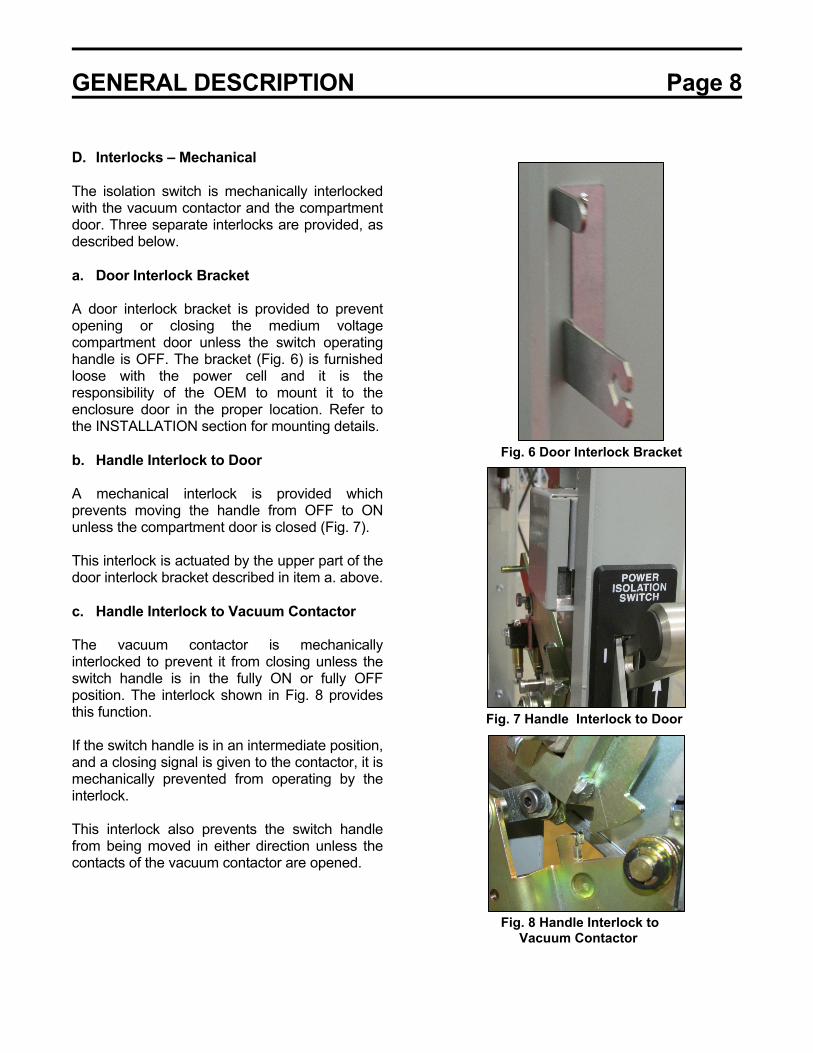
D. Interlocks – Mechanical The isolation switch is mechanically interlocked with the vacuum contactor and the compartment door. Three separate interlocks are provided, as described below. a. Door Interlock Bracket A door interlock bracket is provided to prevent opening or closing the medium voltage compartment door unless the switch operating handle is OFF. The bracket (Fig. 6) is furnished loose with the power cell and it is the responsibility of the OEM to mount it to the enclosure door in the proper location. Refer to the INSTALLATION section for mounting details. b. Handle Interlock to Door A mechanical interlock is provided which prevents moving the handle from OFF to ON unless the compartment door is closed (Fig. 7). This interlock is actuated by the upper part of the door interlock bracket described in item a. above. c. Handle Interlock to Vacuum Contactor The vacuum contactor is mechanically interlocked to prevent it from closing unless the switch handle is in the fully ON or fully OFF position. The interlock shown in Fig. 8 provides this function. If the switch handle is in an intermediate position, and a closing signal is given to the contactor, it is mechanically prevented from operating by the interlock. This interlock also prevents the switch handle from being moved in either direction unless the contacts of the vacuum contactor are opened.
Fig. 6 Door Interlock Bracket Fig. 7 Handle Interlock to Door
Fig. 8 Handle Interlock to Vacuum Contactor
GENERAL DESCRIPTION Page 9
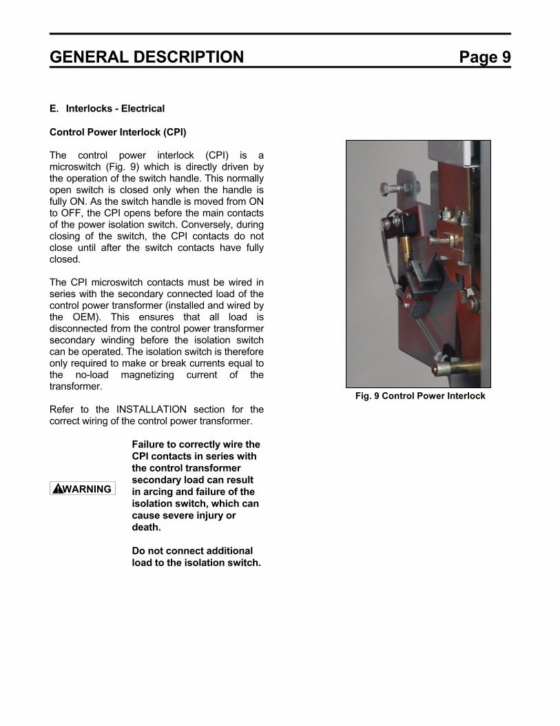
E. Interlocks - Electrical Control Power Interlock (CPI) The control power interlock (CPI) is a microswitch (Fig. 9) which is directly driven by the operation of the switch handle. This normally open switch is closed only when the handle is fully ON. As the switch handle is moved from ON to OFF, the CPI opens before the main contacts of the power isolation switch. Conversely, during closing of the switch, the CPI contacts do not close until after the switch contacts have fully closed. The CPI microswitch contacts must be wired in series with the secondary connected load of the control power transformer (installed and wired by the OEM). This ensures that all load is disconnected from the control power transformer secondary winding before the isolation switch can be operated. The isolation switch is therefore only required to make or break currents equal to the no-load magnetizing current of the transformer. Refer to the INSTALLATION section for the correct wiring of the control power transformer. Failure to correctly wire the
CPI contacts in series with the control transformer secondary load can result in arcing and failure of the isolation switch, which can cause severe injury or death.
Do not connect additional load to the isolation switch.
Fig. 9 Control Power Interlock
WARNING
GENERAL DESCRIPTION Page 10
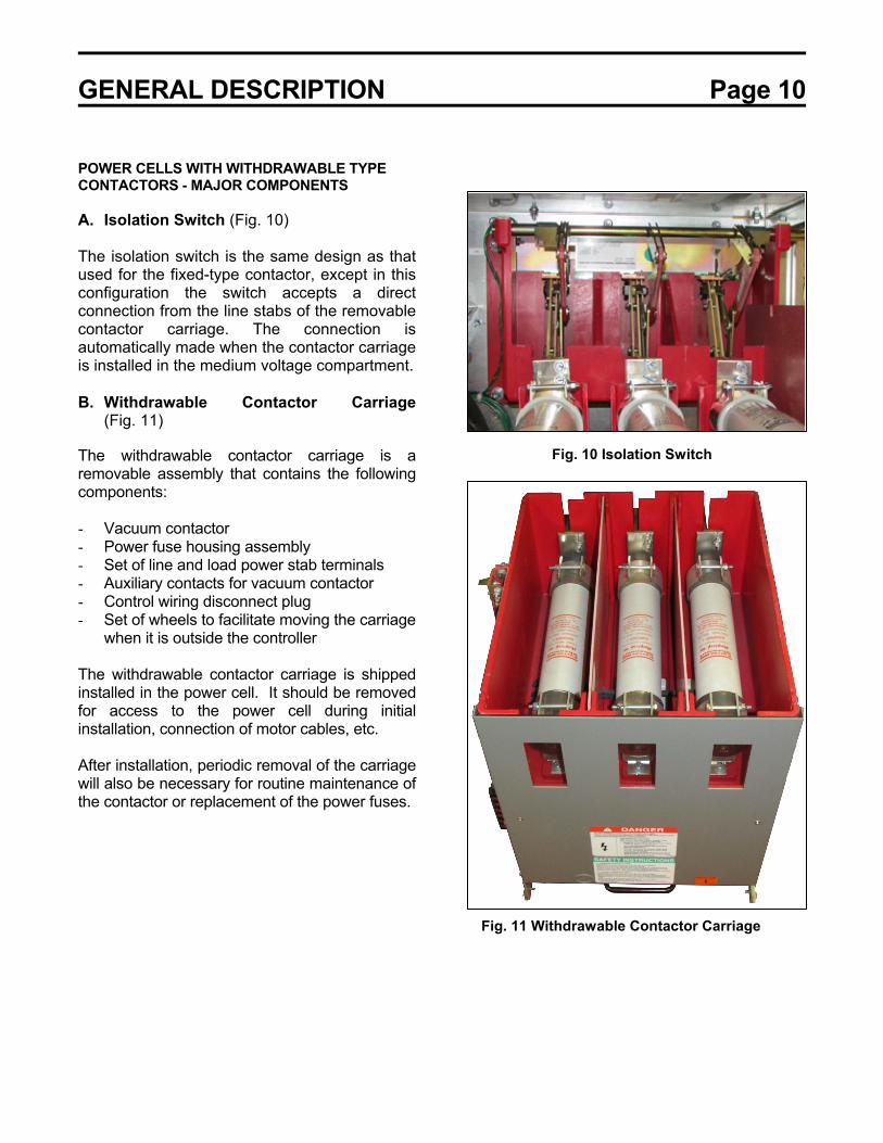
POWER CELLS WITH WITHDRAWABLE TYPE CONTACTORS - MAJOR COMPONENTS A. Isolation Switch (Fig. 10) The isolation switch is the same design as that used for the fixed-type contactor, except in this configuration the switch accepts a direct connection from the line stabs of the removable contactor carriage. The connection is automatically made when the contactor carriage is installed in the medium voltage compartment. B. Withdrawable Contactor Carriage
(Fig. 11) The withdrawable contactor carriage is a removable assembly that contains the following components: - Vacuum contactor - Power fuse housing assembly - Set of line and load power stab terminals - Auxiliary contacts for vacuum contactor - Control wiring disconnect plug - Set of wheels to facilitate moving the carriage
when it is outside the controller The withdrawable contactor carriage is shipped installed in the power cell. It should be removed for access to the power cell during initial installation, connection of motor cables, etc. After installation, periodic removal of the carriage will also be necessary for routine maintenance of the contactor or replacement of the power fuses.
Fig. 10 Isolation Switch
Fig. 11 Withdrawable Contactor Carriage

GENERAL DESCRIPTION Page 11
C. Service Drawer (Fig. 12) The withdrawable contactor carriage is moved in and out of the power cell on a built-in slide-out service drawer. The drawer has four locating pins on top of it. When the contactor carriage is placed on the drawer, these pins engage four holes in the bottom of the carriage, which serve to align it properly. The drawer moves in and out of the power cell on sliding ball-bearing type rails. There is a handle on the front of the drawer to provide a gripping point. When the carriage is installed in the power cell, the following connections are automatically made: 1) The line side stabs engage the fixed-
mounted isolation switch connecting the load side of the switch to the line side of the power fuses.
2) The load side stabs engage the fixed-
mounted load receptacle connecting the load side of the vacuum contactor to the outgoing cell terminals.
3) Medium voltage control power take-off stabs
engage stationary clips on the left side of the cell, providing a connection point for the OEM to derive primary power for the control power transformer. These take-off stabs are electrically connected to the load side of the main power fuses.
D. Load Receptacle (Fig. 13) The load receptacle is a fixed three-phase disconnecting block, which uses bolted pressure type stab contacts similar to those used in the isolation switch. The vacuum contactor load stabs on the withdrawable carriage engage the load receptacle when the carriage is installed. The operation of the bolted pressure contact mechanism is controlled by a release lever located at the front of the power cell below the service drawer. Outgoing load cables are to be connected by the OEM to the terminal pads that are furnished on the rear of the load receptacle.
Fig. 12 Service Drawer
Fig. 13 Load Receptacle

GENERAL DESCRIPTION Page 12
E. Interlocks - Mechanical When the withdrawable contactor carriage is inserted into the power cell, mechanical interlocking is established between the isolation switch, the vacuum contactor and the compartment door. a. Door Interlock Bracket A door interlock bracket is provided to prevent opening or closing the medium voltage compartment door unless the switch operating handle is OFF. This interlock is the same as that furnished on cells with fixed-type contactors (refer to Fig. 6). b. Handle Interlock to Door A mechanical interlock is provided which prevents moving the handle from OFF to ON unless the compartment door is closed. This interlock is the same as that furnished on cells with fixed-type contactors (refer to Fig. 7). c. Handle Interlock to Vacuum Contactor The vacuum contactor is mechanically interlocked to prevent it from closing unless the switch handle is in the fully ON or fully OFF position. The interlock shown in Fig. 14 provides this function. If the switch handle is in an intermediate position, and a closing signal is given to the contactor, it is mechanically prevented from operating by the interlock. This interlock also prevents the switch handle from being moved in either direction unless the contacts of the vacuum contactor are opened. F. Interlocks - Electrical Control Power Interlock (CPI) The control power interlock microswitch is the same as that furnished on cells with fixed-type contactors (refer to Fig. 9).
Fig. 14 Handle Interlock to Vacuum Contactor

RECEIVING, INSPECTION AND HANDLING Page 13
FRONT
A
A/2
45°
LIFTING POINT
RECEIVING AND UNPACKING The OEM components are subjected to factory production alignment and testing prior to being packed and shipped. ACCEPTANCE INSPECTION Confirm that the power cell and withdrawable contactor carriage (if furnished) are complete, correct as specified and undamaged from shipment and handling. Upon receipt of the equipment, do the following: 1) Make an immediate inspection for damage
which might have occurred during shipment. If damage is discovered, it should be noted with the carrier prior to accepting the shipment, if possible.
2) Carefully unpack the equipment sufficiently to
check for missing parts or concealed damage.
3) Keep the components upright.
Never lay the power cell or the contactor carriage on their sides or upside down. This may cause damage.
4) File a claim with the carrier for any damaged
or missing items and immediately notify the nearest Toshiba representative.
Do not install or energize equipment that has been damaged. Damaged equipment can fail during operation, resulting in fire and explosion.
HANDLING AND MOVING THE POWER CELL When handling and moving the power cell, the suspension technique shown in Fig. 15 should be used.
Fig. 15 Lifting Method for Power Cell (Fixed-Type and Withdrawable Contactor)
CAUTION
WARNING
RECEIVING, INSPECTION AND HANDLING Page 14
SHIPPINGBRACKET
ATTACH OVERHEAD
SIDE
SUPPORTARM
LIFT
BOLT
DRAWER BASE
(REMOVE BEFORE LIFTING FROM
DRAWER)
LIFTER HERE
LEFT FRONT
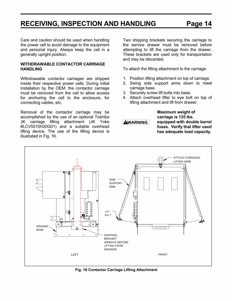
Care and caution should be used when handling the power cell to avoid damage to the equipment and personal injury. Always keep the cell in a generally upright position. WITHDRAWABLE CONTACTOR CARRIAGE HANDLING Withdrawable contactor carriages are shipped inside their respective power cells. During initial installation by the OEM, the contactor carriage must be removed from the cell to allow access for anchoring the cell to the enclosure, for connecting cables, etc. Removal of the contactor carriage may be accomplished by the use of an optional Toshiba JK carriage lifting attachment (JK Yoke #LCV5010H20G01) and a suitable overhead lifting device. The use of the lifting device is illustrated in Fig. 16.
Two shipping brackets securing the carriage to the service drawer must be removed before attempting to lift the carriage from the drawer. These brackets are used only for transportation and may be discarded. To attach the lifting attachment to the carriage: 1. Position lifting attachment on top of carriage. 2. Swing side support arms down to meet
carriage base. 3. Securely screw lift bolts into base. 4. Attach overhead lifter to eye bolt on top of
lifting attachment and lift from drawer. Maximum weight of
carriage is 135 lbs. equipped with double barrel fuses. Verify that lifter used has adequate load capacity.
Fig. 16 Contactor Carriage Lifting Attachment
WARNING

INSTALLATION Page 15
OEM ENCLOSURE DESIGN These power cells should be totally enclosed in sheet metal structures that comply with the applicable requirements of NEMA Standards Publications ICS 6 and 250 for enclosures for industrial systems. The minimum controller compartment size is 30 inches wide by 30 inches high by 36 inches deep. The power cell must be securely attached to the floor of the controller compartment. Four holes are provided in the cell base for anchoring using 5/16-18 bolts or studs. In addition, four threaded inserts are provided which will accept 5/16-18 bolts installed from the underside of the cell, for use if the compartment floor is located above floor level. Refer to Fig. 17 for location of mounting points.
The right front corner of the OEM structure should include a flange of approximately 4 inches in width with a cutout for the operating handle to extend through. The dimensions and location of the handle cutout are given in Fig. 20. The cell should be positioned in the enclosure as far to the right and as far to the front as possible. The compartment door should have flanged edges, which result in a dimension of 1.25 inches from the inside of the door to the front of the cell as shown in Fig. 20. The door interlock that is provided with the kit should be attached to the inside of enclosure door at the specified location (Fig. 20).
Fig. 17 Power Cell Mounting

INSTALLATION Page 16
Fig. 18 Line and Load Terminal Locations with Withdrawable Type Contactor
Fig. 19 Line and Load Terminal Locations with Fixed Type Contactor
5.00 5.00 8.84
1.00
5.36 4.53 4.53
9.60
4.37
(3) LINETERMINAL
(3) LINETERMINAL
4.25
20.03
9.75
(3) LOADTERMINAL

INSTALLATION Page 17
Fig. 20 Enclosure Specifications, Handle Location, and Door Interlock Location with Fixed and Withdrawable Type Contactors
3 6 .00 M IN IM U M
3 0 .0 0 M IN IM U M
O EM ENCLO SURE
F R O N T V IE W
O EM ENCLO SUR
JK S T A R T E R
T O P V IE W
3 0 .0 0 M IN IM U M
3 0 .0 0 M IN IM U M
JK S T A R T E R
4 .5 0
0 .7 5
1 6 .3 3
2 .5 5
CO NTRO L POW ER
CO NNECTO R LO CATIO N
(W ITHDRAW ABLE TYPE O NLY)
CL
1 .5 6
CL
O E M C E L L W A L L
C E L L M O D U L ER IG H T F R O N T P O S T
1 .4 3 1 .1 31 .1 6
0 .4 2
1 .2 9
D O O R IN T E R L O C K
1 .6 7
2 .2 5
1 .8 1
1 .7 0
D O O R IN T E R L O C K(O N IN S ID E O F D O O R )
C U T O U T F O R H A N D L E
1 4 .58
O E M C E L L D O O R
F IG U R E A
F IG U R E A
F IG U R E C
F IG U R E C
F IG U R E B – D O O R IN T E R L O C K
3 .4 4 0 .2 3 0 .2 30 .2 7
0 .5 0 4 - 0 .1 7 3
2 .8 1
O E M E N C L O S U R E D O O R

INSTALLATION Page 18
MAIN CIRCUIT CABLING Cables which connect to the power cell should be routed to avoid interference with sharp edges and moving parts. Minimum bending radius for the type of cable used should be observed. Power cables should be braced and/or laced to withstand short-circuit forces wherever such cables are unsupported. Power cables should be adequately sized to carry the maximum continuous current and should have an adequate voltage rating. The OEM should perform a temperature rise test on the completed controller to verify compliance with the temperature rise requirements of NEMA ICS3 Part 2. It is recommended that a cable size of at least 4/0 AWG be used throughout the power circuit for continuous ratings up to 360A. It should be noted, however, that the maximum obtainable continuous current rating of the controller might be less than 360A in some cases. This is due to a number of factors that have an influence on temperature rise, including: - Ventilation provided (enclosure type) - Number of controllers stacked vertically - Controller position within a stacking
arrangement

OPERATION Page 19
CONTACTOR INSTALLATION To install the contactor carriage in the controller: 1) Lift and pull the release lever out all the
way (see Fig. 21) and pull out the service drawer.
To avoid tipping over,
the controller enclosure must be securely bolted to the floor.
2) Lift and place the contactor carriage on
the service drawer (Fig. 12). The front of the carriage should line up with the front of the drawer, and the four locator pins on top of the drawer should engage the holes in the bottom of the carriage. Installation of the contactor carriages in the upper compartments of the one- and two-high stacking arrangements requires the use of a Toshiba JK lifting device.
Manually lifting heavy
equipment can cause serious injury. Use a Toshiba JK lifting device.
3) With the carriage properly in place on
the service drawer, push the drawer firmly all the way into the compartment. Then push the release lever in until it drops slightly and latches. This operation causes the load receptacle to apply bolted pressure to the load stabs of the carriage.
Fig. 21 Release Lever Pulled Out, Withdrawable Type Contactor
The release lever must be pushed in (Fig. 22) before the isolation switch is closed or the controller is operated under load. The medium voltage compartment door cannot be closed unless the release lever is pushed in. A mechanical interlock prevents the isolation switch from being closed unless the medium voltage door is closed. Release lever must be
pushed in and latched before operating the controller.
Fig. 22 Release Lever Pushed In and Closed, Withdrawable Type Contactor
WARNING
WARNING
WARNING

MAINTENANCE Page 20
SWITCH HANDLE MECHANISM The handle mechanism, which operates the isolation switch, is adjusted at the factory and under normal operation requires no further adjustment. Adjustment can be checked, however, as follows (Fig. 23): 1) Move the handle to full OFF position. 2) Observe that isolation switchblades are in
contact with the ground pads. 3) If adjustment is required, loosen lock nut
securing yoke on handle end of connecting rod. Remove pin that attaches yoke to handle drive lever. Turn yoke in required direction to achieve adjustment defined in step 2. Re-attach yoke and pin to drive lever and tighten yoke lock nut.
The moving joints should be occasionally lubricated with a light coat of Toshiba B9 grease.
INTERLOCKS - Circumvent the handle interlock by pushing a screwdriver through the slot and operate the handle several times.
- Check that the CPI electrical interlock (microswitch) operates each time the handle is moved. The CPI (control power interlock) should close approximately 10º before the handle reaches the full ON position. As the handle is moved from ON to OFF, the CPI switch should open by the time the handle has moved approximately 10º or one inch.
- Check that the handle interlock to the vacuum contactor operates freely. Lubricate with Toshiba B9 grease if necessary. Refer to the GENERAL DESCRIPTION section for the location of the handle mechanical interlocks and the CPI electrical interlock.
Fig. 23 Interlock Sequence Check

SPECIFICATIONS Page 21
CONTACTOR RATINGS
TABLE 1 CONTACTOR TYPE HCV-5HA/5HAM (Magnetically Held)
Maximum Voltage 7200 Volts
Rated Operational Current 400 Amps
Rated Thermal Current 450 Amps
Interrupting Capacity (NEMA Class E1) 7000 Amps RMS Sym. @ 5 kV Max 4500 Amps RMS Sym. @ 7.2 kV Max
Permissible Switching Frequency 1200/Hour
Mechanical Life 2,500,000 Operations
Electrical Life 250,000 Operations
Closing Time 75-100 ms
Opening Time 20-30 ms
Arcing Time 10 ms or less
Pick-Up Voltage AC or DC 85% (Hot) – 70% (Cold)
Drop-Out Voltage AC or DC 50% (Hot) – 40% (Cold)
Rated Control Voltage AC * 115/120 or 230/240V 50/60 Hz
Rated Control Voltage DC * 120/125 or 240/250V
Coil Circuit Inrush 5.4A Peak @ 120Vac (670VA AC (700W DC)
Coil Circuit Holding 0.12A Average @ 120Vac (85VA AC - 85W DC)
Auxiliary Contact Arrangement 3 N.O. – 3 N.C. (Max-STD)
Auxiliary Contact Rating 10 A, 48-600Vac Max. (NEMA Class A600)
* Coil drive board setting required (standard 120 Vac). Refer to contactor manual VF00W103. CONTACTOR TYPE HCV-5HAL/HAML (Latched Type)
Permissible Switching Frequency 300/Hour
Mechanical Life 250,000 Operations
Tripping Voltage 60% or less of Coil Rating DC (Cold)
Tripping Current 4.8A Peak @ 125Vdc
A latched contactor is the same as magnetically-held type, except number of auxiliary contacts is reduced to 2 N.O. – 2 N.C. Standard operating voltage is 120VAC Close/125VDC Trip.

SCHEMATIC DIAGRAMS Page 22
Fig. 24 Suggested Schematic for Medium Voltage FVNR Starter with Withdrawable Contactor
SCHEMATIC DIAGRAMS Page 23
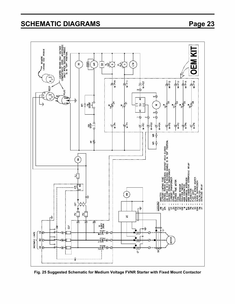
Fig. 25 Suggested Schematic for Medium Voltage FVNR Starter with Fixed Mount Contactor
KEY INTERLOCK OPTION Page 25
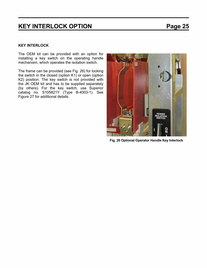
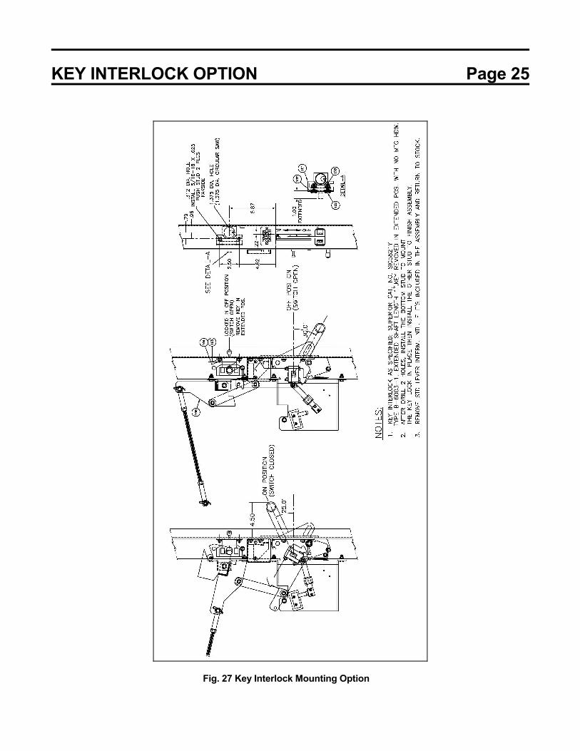
KEY INTERLOCK The OEM kit can be provided with an option for installing a key switch on the operating handle mechanism, which operates the isolation switch. The frame can be provided (see Fig. 26) for locking the switch in the closed (option K1) or open (option K2) position. The key switch is not provided with the JK OEM kit and has to be supplied separately (by others). For the key switch, use Superior catalog no. S105821Y (Type B-4003-1). See Figure 27 for additional details. Fig. 26 Optional Operator Handle Key Interlock
KEY INTERLOCK OPTION Page 25
Fig. 27 Key Interlock Mounting Option


Transmission & Distribution Division 13131 West Little York Road | Houston, TX 77041 Tel: 713-466-0277 | US: 800-231-1412 | CAN: 800-872-2192 www.toshiba.com/tic Printed in USA