vfd68 variable frequency drive (575 vac) installation...
TRANSCRIPT
Refer to the QuickLIT website for the most up-to-date version of this document.
VFD68 Variable Frequency Drive (575 VAC)Installation InstructionsVFD68Dxx Part No. 24-7664-3116, Rev. D
Issued October 2017
Introduction . . . . . . . . . . . . . . . . . . . . . . . . . . . . . . . . . . . . . . . . . . . . . . . . . . . . . . . . . . . . . . . .3
North American Emissions Compliance . . . . . . . . . . . . . . . . . . . . . . . . . . . . . . . . . . . . . . . . .3
United States . . . . . . . . . . . . . . . . . . . . . . . . . . . . . . . . . . . . . . . . . . . . . . . . . . . . . . . . . . . . . . . . . . 3
Canada . . . . . . . . . . . . . . . . . . . . . . . . . . . . . . . . . . . . . . . . . . . . . . . . . . . . . . . . . . . . . . . . . . . . . . . 3
Agency Standards Compliance . . . . . . . . . . . . . . . . . . . . . . . . . . . . . . . . . . . . . . . . . . . . . . . . . . . 4
Installation . . . . . . . . . . . . . . . . . . . . . . . . . . . . . . . . . . . . . . . . . . . . . . . . . . . . . . . . . . . . . . . . .4
Checking the Rating Plate. . . . . . . . . . . . . . . . . . . . . . . . . . . . . . . . . . . . . . . . . . . . . . . . . . . . . . . . 4
Selecting a Motor . . . . . . . . . . . . . . . . . . . . . . . . . . . . . . . . . . . . . . . . . . . . . . . . . . . . . . . . . . . . . . 5
Selecting a VFD68 Drive for Controlling Multiple Motors . . . . . . . . . . . . . . . . . . . . . . . . . . . . . . 5
Location Considerations . . . . . . . . . . . . . . . . . . . . . . . . . . . . . . . . . . . . . . . . . . . . . . . . . . . . . . . 5
Dimensions . . . . . . . . . . . . . . . . . . . . . . . . . . . . . . . . . . . . . . . . . . . . . . . . . . . . . . . . . . . . . . . . . . . 7
Mounting . . . . . . . . . . . . . . . . . . . . . . . . . . . . . . . . . . . . . . . . . . . . . . . . . . . . . . . . . . . . . . . . . .8
Wiring . . . . . . . . . . . . . . . . . . . . . . . . . . . . . . . . . . . . . . . . . . . . . . . . . . . . . . . . . . . . . . . . . . . .10
Precautions . . . . . . . . . . . . . . . . . . . . . . . . . . . . . . . . . . . . . . . . . . . . . . . . . . . . . . . . . . . . . . . . . . 11
Terminal Screw Torque Specifications . . . . . . . . . . . . . . . . . . . . . . . . . . . . . . . . . . . . . . . . . . . . 12
Branch Circuit Protection . . . . . . . . . . . . . . . . . . . . . . . . . . . . . . . . . . . . . . . . . . . . . . . . . . . . . . . 12
Short Circuit Ratings . . . . . . . . . . . . . . . . . . . . . . . . . . . . . . . . . . . . . . . . . . . . . . . . . . . . . . . . . . . . 12
High-Voltage Wire Size and Maximum Wire Length . . . . . . . . . . . . . . . . . . . . . . . . . . . . . . . . . . 13
Selecting the Correct VFD68 Drive for a Fan Motor . . . . . . . . . . . . . . . . . . . . . . . . . . . . . . . . . . . . 13
Calculating the Maximum Wire Length . . . . . . . . . . . . . . . . . . . . . . . . . . . . . . . . . . . . . . . . . . . . . . 14
Making High-Voltage Wiring Connections . . . . . . . . . . . . . . . . . . . . . . . . . . . . . . . . . . . . . . . . . 15
Making Low-Voltage Wiring Connections . . . . . . . . . . . . . . . . . . . . . . . . . . . . . . . . . . . . . . . . . . 17
Input Wiring Connections. . . . . . . . . . . . . . . . . . . . . . . . . . . . . . . . . . . . . . . . . . . . . . . . . . . . . . . . . 19
Setup and Adjustment . . . . . . . . . . . . . . . . . . . . . . . . . . . . . . . . . . . . . . . . . . . . . . . . . . . . . .20
Correspondences Between Digital and Actual Characters . . . . . . . . . . . . . . . . . . . . . . . . . . . . 20
VFD68 Variable Frequency Drive (575 VAC) Installation Instructions
1
Operation Modes . . . . . . . . . . . . . . . . . . . . . . . . . . . . . . . . . . . . . . . . . . . . . . . . . . . . . . . . . . . . . . 20
Mode of Operation Icons . . . . . . . . . . . . . . . . . . . . . . . . . . . . . . . . . . . . . . . . . . . . . . . . . . . . . . . . . 20
Display Code . . . . . . . . . . . . . . . . . . . . . . . . . . . . . . . . . . . . . . . . . . . . . . . . . . . . . . . . . . . . . . . . . . 20
VFD68Dxx Drive Parameters. . . . . . . . . . . . . . . . . . . . . . . . . . . . . . . . . . . . . . . . . . . . . . . . . . . . . 22
Frequency and Motor Speed. . . . . . . . . . . . . . . . . . . . . . . . . . . . . . . . . . . . . . . . . . . . . . . . . . . . . 24
Parameter Settings Calculations for Motor Speed vs. Pressure . . . . . . . . . . . . . . . . . . . . . . 25
PWM Frequency, Audible Motor Noise, and EMI . . . . . . . . . . . . . . . . . . . . . . . . . . . . . . . . . . . . 25
Adjusting the Default Parameters . . . . . . . . . . . . . . . . . . . . . . . . . . . . . . . . . . . . . . . . . . . . . . . . 26
Enter the Parameter Adjustment Mode . . . . . . . . . . . . . . . . . . . . . . . . . . . . . . . . . . . . . . . . . . . . . . 26
Select and Change Most Parameters . . . . . . . . . . . . . . . . . . . . . . . . . . . . . . . . . . . . . . . . . . . . . . . 26
Select and Change P.90x Parameters. . . . . . . . . . . . . . . . . . . . . . . . . . . . . . . . . . . . . . . . . . . . . . . 26
Exit the Parameter Adjustment Mode . . . . . . . . . . . . . . . . . . . . . . . . . . . . . . . . . . . . . . . . . . . . . . . 27
Manual Motor Speed Control in PU Mode . . . . . . . . . . . . . . . . . . . . . . . . . . . . . . . . . . . . . . . . . . 27
EXT Mode Using Analog Inputs . . . . . . . . . . . . . . . . . . . . . . . . . . . . . . . . . . . . . . . . . . . . . . . . . . 27
Troubleshooting . . . . . . . . . . . . . . . . . . . . . . . . . . . . . . . . . . . . . . . . . . . . . . . . . . . . . . . . . . .27
Resetting the VFD68 Drive . . . . . . . . . . . . . . . . . . . . . . . . . . . . . . . . . . . . . . . . . . . . . . . . . . . . . . 30
Reset Option 1 . . . . . . . . . . . . . . . . . . . . . . . . . . . . . . . . . . . . . . . . . . . . . . . . . . . . . . . . . . . . . . . . . 30
Reset Option 2 . . . . . . . . . . . . . . . . . . . . . . . . . . . . . . . . . . . . . . . . . . . . . . . . . . . . . . . . . . . . . . . . . 30
Manually Stopping the Motor . . . . . . . . . . . . . . . . . . . . . . . . . . . . . . . . . . . . . . . . . . . . . . . . . . . . 30
Restarting the Motor After It Has Stopped . . . . . . . . . . . . . . . . . . . . . . . . . . . . . . . . . . . . . . . . . 31
Technical Specifications . . . . . . . . . . . . . . . . . . . . . . . . . . . . . . . . . . . . . . . . . . . . . . . . . . . .32
VFD68Dxx Variable Frequency Drive (575 VAC) . . . . . . . . . . . . . . . . . . . . . . . . . . . . . . . . . . . . . 32
VFD68 Variable Frequency Drive (575 VAC) Installation Instructions
2

VFD68 Variable Frequency Drives (575 VAC)
IntroductionThe VFD68 Variable Frequency Drives are designed to provide three-phase motor speed control in a variety of HVACR applications. The VFD68 Drives are factory-configured for condenser fan speed control on HVACR condensing units. You can quickly and easily reconfigure the VFD68 Drives to control variable speed pumps in cooling and heating applications, or to drive variable speed supply fans in VAV applications.
This document provides information for VFD68Dxx (575 VAC) Drive models only. For information pertaining to VFD68Bxx (230 VAC) and VFD68Cxx (460 VAC) Drive models, refer to the VFD68 Variable Frequency Drive (230 or 460 VAC) Installation Instructions (Part No. 24-7664-3108).
Note: The VFD68 Drive cannot drive motors in conveyor systems or robotic applications.
Note: Do not attempt to install, operate, maintain, or inspect the VFD68 Drive until you have read through this document carefully and can use the equipment correctly. Do not use this product until you fully understand the equipment, safety information, and instructions.
To view the VFD68 Variable Frequency Drive Technical Bulletin (Part No. 24-7664-3051), which covers 230 VAC, 460 VAC, and 575 VAC models, visit the following web address: http://cgproducts.johnsoncontrols.com/MET_PDF/2476643051.pdf
North American Emissions Compliance
United States
Canada
IMPORTANT: Use this VFD68 Variable Frequency Drive only as an operating control. Where failure or malfunction of the VFD68 Drive could lead to personal injury or property damage to the controlled equipment or other property, additional precautions must be designed into the control system. Incorporate and maintain other devices, such as supervisory or alarm systems or safety or limit controls, intended to warn of or protect against failure or malfunction of the VFD68 Drive.
IMPORTANT: Utiliser ce VFD68 Variable Frequency Drive uniquement en tant que dispositif de régulation. Lorsqu'une défaillance ou un dysfonctionnement du VFD68 Drive risque de provoquer des blessures ou d'endommager l'équipement contrôlé ou un autre équipement, la conception du système de contrôle doit intégrer des dispositifs de protection supplémentaires. Veiller dans ce cas à intégrer de façon permanente d'autres dispositifs, tels que des systèmes de supervision ou d'alarme, ou des dispositifs de sécurité ou de limitation, ayant une fonction d'avertissement ou de protection en cas de défaillance ou de dysfonctionnement du VFD68 Drive.
This equipment has been tested and found to comply with the limits for a Class A digital device pursuant to Part 15 of the FCC Rules. These limits are designed to provide reasonable protection against harmful interference when this equipment is operated in a commercial environment. This equipment generates, uses, and can radiate radio frequency energy and, if not installed and used in accordance with the instruction manual, may cause harmful interference to radio communications. Operation of this equipment in a residential area may cause harmful interference, in which case users will be required to correct the interference at their own expense.
This Class (A) digital apparatus meets all the requirements of the Canadian Interference-Causing Equipment Regulations.
Cet appareil numérique de la Classe (A) respecte toutes les exigences du Règlement sur le matériel brouilleur du Canada.
VFD68 Variable Frequency Drives (575 VAC)
3
Agency Standards Compliance• North America: cULus Listed; UL 508C, USA File: NMMS.E244421; Canada File: NMMS7.E244421
Installation
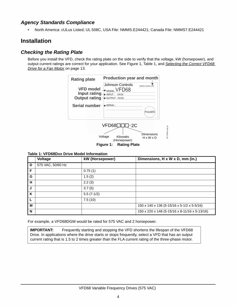
Checking the Rating PlateBefore you install the VFD, check the rating plate on the side to verify that the voltage, kW (horsepower), and output current ratings are correct for your application. See Figure 1, Table 1, and Selecting the Correct VFD68 Drive for a Fan Motor on page 13.
For example, a VFD68DGM would be rated for 575 VAC and 2 horsepower.
Table 1: VFD68Dxx Drive Model InformationVoltage kW (Horsepower) Dimensions, H x W x D, mm (in.)
D 575 VAC, 50/60 Hz
F 0.75 (1)
G 1.5 (2)
H 2.2 (3)
J 3.7 (5)
K 5.5 (7-1/2)
L 7.5 (10)
M 150 x 140 x 136 (5-15/16 x 5-1/2 x 5-5/16)
N 150 x 220 x 148 (5-15/16 x 8-11/16 x 5-13/16)
IMPORTANT: Frequently starting and stopping the VFD shortens the lifespan of the VFD68 Drive. In applications where the drive starts or stops frequently, select a VFD that has an output current rating that is 1.5 to 2 times greater than the FLA current rating of the three-phase motor.
Figure 1: Rating Plate
Rating plate
VFD modelInput rating
Output rating
Serial number
DATE:XXXX-XX
Production year and month
Johnson Controls
VFD68 -2C
Voltage Kilowatts(Horsepower)
Dimensions H x W x D FI
G:V
FD68
_rtn
g_pl
t
SERIAL :
OUTPUT : XXXX
INPUT : XXXX
MODEL
VFD68 Variable Frequency Drives (575 VAC)
4
Selecting a Motor
Motors used with the VFD68Dxx Drive must:
• be AC induction three-phase motors that are UL Recognized and CSA Certified, or equivalent
• be rated for 575 VAC at 60 Hz
• have an Inverter Rating
• have Insulation Class F or better
The VFD68 Drive is intended for use with variable speed motors that are rated for 40:1 operation.
Note: If three-phase power is not available as supply power for the VFD68 Drive, refer to the VFD68 Variable Frequency Drive Technical Bulletin (Part No. 24-7664-3051).
Selecting a VFD68 Drive for Controlling Multiple Motors
A VFD68 Drive can control multiple motors wired in parallel; however, the sum of the Full Load Amperes (FLA) ratings for the motors must not exceed the maximum output current rating of the VFD68 Drive, including any de-rating due to altitude. See Table 2 on page 6 for derating information.
Location Considerations
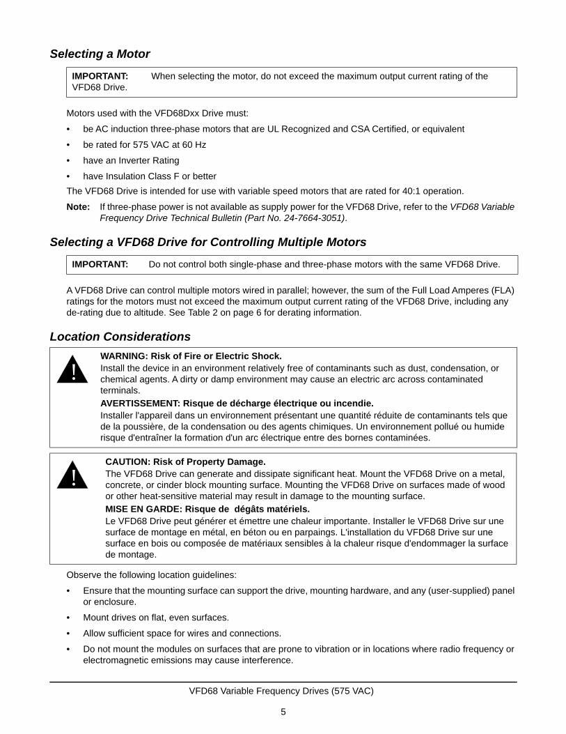
Observe the following location guidelines:
• Ensure that the mounting surface can support the drive, mounting hardware, and any (user-supplied) panel or enclosure.
• Mount drives on flat, even surfaces.
• Allow sufficient space for wires and connections.
• Do not mount the modules on surfaces that are prone to vibration or in locations where radio frequency or electromagnetic emissions may cause interference.
IMPORTANT: When selecting the motor, do not exceed the maximum output current rating of the VFD68 Drive.
IMPORTANT: Do not control both single-phase and three-phase motors with the same VFD68 Drive.
!WARNING: Risk of Fire or Electric Shock.Install the device in an environment relatively free of contaminants such as dust, condensation, or chemical agents. A dirty or damp environment may cause an electric arc across contaminated terminals.
AVERTISSEMENT: Risque de décharge électrique ou incendie.Installer l'appareil dans un environnement présentant une quantité réduite de contaminants tels que de la poussière, de la condensation ou des agents chimiques. Un environnement pollué ou humide risque d'entraîner la formation d'un arc électrique entre des bornes contaminées.
!CAUTION: Risk of Property Damage.The VFD68 Drive can generate and dissipate significant heat. Mount the VFD68 Drive on a metal, concrete, or cinder block mounting surface. Mounting the VFD68 Drive on surfaces made of wood or other heat-sensitive material may result in damage to the mounting surface.
MISE EN GARDE: Risque de dégâts matériels.Le VFD68 Drive peut générer et émettre une chaleur importante. Installer le VFD68 Drive sur une surface de montage en métal, en béton ou en parpaings. L'installation du VFD68 Drive sur une surface en bois ou composée de matériaux sensibles à la chaleur risque d'endommager la surface de montage.
VFD68 Variable Frequency Drives (575 VAC)
5
• Do not install the modules in airtight enclosures.
• Do not install heat-generating devices that may cause the temperature to exceed the ambient operating limit in the same enclosure as the modules.
The VFD68 Drive has been approved for use in an enclosure. Approval tests were conducted under the conditions in Table 2.
When mounting the VFD68 Drive in an enclosure, ensure that the specified space around the drive is
maintained, and that the ambient conditions are within the specified limits.
IMPORTANT: The drive is intended to be mounted in an enclosure that only allows access by trained and authorized personnel, and that prevents the ingress of contamination. It is designed for use in an environment classified as pollution degree 2 in accordance with IEC 60664-1. This means that only dry, non-conducting contamination is acceptable.
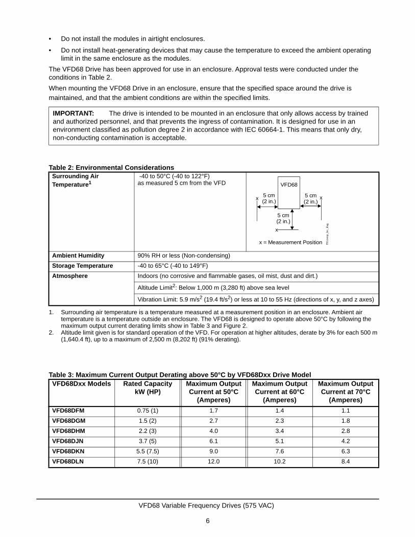
Table 2: Environmental ConsiderationsSurrounding Air Temperature1
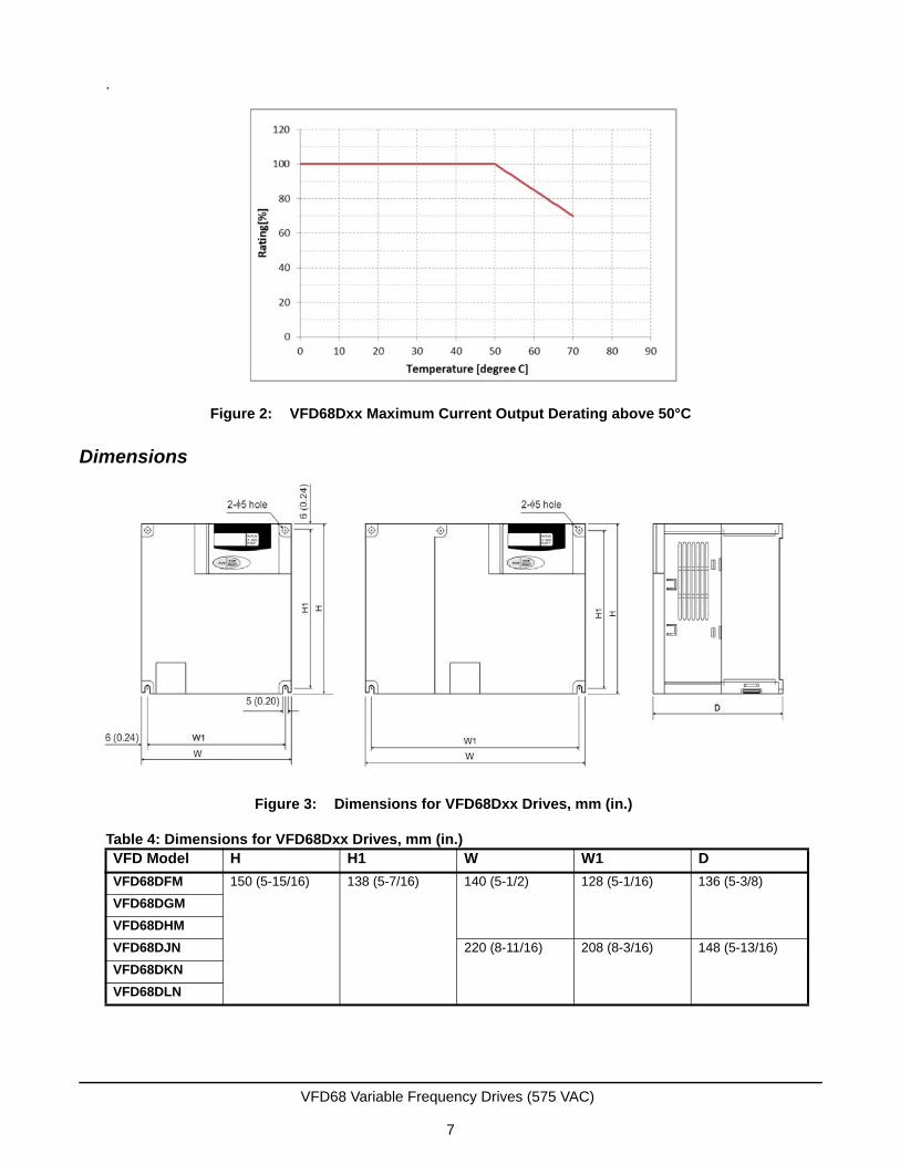
1. Surrounding air temperature is a temperature measured at a measurement position in an enclosure. Ambient air temperature is a temperature outside an enclosure. The VFD68 is designed to operate above 50°C by following the maximum output current derating limits show in Table 3 and Figure 2.
-40 to 50°C (-40 to 122°F)as measured 5 cm from the VFD
Ambient Humidity 90% RH or less (Non-condensing)
Storage Temperature -40 to 65°C (-40 to 149°F)
Atmosphere Indoors (no corrosive and flammable gases, oil mist, dust and dirt.)
Altitude Limit2: Below 1,000 m (3,280 ft) above sea level
2. Altitude limit given is for standard operation of the VFD. For operation at higher altitudes, derate by 3% for each 500 m (1,640.4 ft), up to a maximum of 2,500 m (8,202 ft) (91% derating).
Vibration Limit: 5.9 m/s2 (19.4 ft/s2) or less at 10 to 55 Hz (directions of x, y, and z axes)
Table 3: Maximum Current Output Derating above 50°C by VFD68Dxx Drive ModelVFD68Dxx Models Rated Capacity
kW (HP) Maximum Output Current at 50°C
(Amperes)
Maximum Output Current at 60°C
(Amperes)
Maximum Output Current at 70°C
(Amperes)
VFD68DFM 0.75 (1) 1.7 1.4 1.1
VFD68DGM 1.5 (2) 2.7 2.3 1.8
VFD68DHM 2.2 (3) 4.0 3.4 2.8
VFD68DJN 3.7 (5) 6.1 5.1 4.2
VFD68DKN 5.5 (7.5) 9.0 7.6 6.3
VFD68DLN 7.5 (10) 12.0 10.2 8.4
VFD68
x = Measurement Position
5 cm(2 in.)
5 cm(2 in.)
5 cm(2 in.)
x
x
x
FIG
:tem
p_lo
c_di
ag
VFD68 Variable Frequency Drives (575 VAC)
6
.
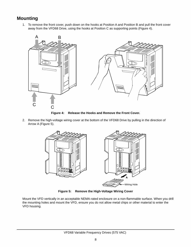
Dimensions
Table 4: Dimensions for VFD68Dxx Drives, mm (in.)VFD Model H H1 W W1 D
VFD68DFM 150 (5-15/16) 138 (5-7/16) 140 (5-1/2) 128 (5-1/16) 136 (5-3/8)
VFD68DGM
VFD68DHM
VFD68DJN 220 (8-11/16) 208 (8-3/16) 148 (5-13/16)
VFD68DKN
VFD68DLN
Figure 2: VFD68Dxx Maximum Current Output Derating above 50°C
Figure 3: Dimensions for VFD68Dxx Drives, mm (in.)
VFD68 Variable Frequency Drives (575 VAC)
7
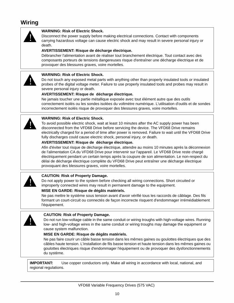
Mounting1. To remove the front cover, push down on the hooks at Position A and Position B and pull the front cover
away from the VFD68 Drive, using the hooks at Position C as supporting points (Figure 4).
2. Remove the high-voltage wiring cover at the bottom of the VFD68 Drive by pulling in the direction of Arrow A (Figure 5).
Mount the VFD vertically in an acceptable NEMA-rated enclosure on a non-flammable surface. When you drill the mounting holes and mount the VFD, ensure you do not allow metal chips or other material to enter the VFD housing.
Figure 4: Release the Hooks and Remove the Front Cover.
Figure 5: Remove the High-Voltage Wiring Cover
Wiring Hole
VFD68 Variable Frequency Drives (575 VAC)
8

See Figure 6 and Table 5 for mounting space requirements.
Table 5: Required ClearanceDimension 3.7 kW (5 HP) or Less 5.5 to 7.5 kW (7-1/2 to 10 HP)
A 100 mm (4 in.) or more 100 mm (4 in.) or more
B 10 mm (7/16 in.) or more 50 mm (2 in.) or more
C
Figure 6: Required Clearance for Mounting Inside an Enclosure
5.5 to 7.5 kW (7-1/2 to 10 HP)
FIG
:clr
nc_r
qrdSide
VFD
3.7 kW (5 HP) or Less
C
A
A
Front
VFD VFDB BB
A A
A A
SideFront
VFD VFD VFD
A A A
A A A
B B B C
VFD68 Variable Frequency Drives (575 VAC)
9
Wiring
!WARNING: Risk of Electric Shock.Disconnect the power supply before making electrical connections. Contact with components carrying hazardous voltage can cause electric shock and may result in severe personal injury or death.
AVERTISSEMENT: Risque de décharge électrique.Débrancher l'alimentation avant de réaliser tout branchement électrique. Tout contact avec des composants porteurs de tensions dangereuses risque d'entraîner une décharge électrique et de provoquer des blessures graves, voire mortelles.
!WARNING: Risk of Electric Shock.Do not touch any exposed metal parts with anything other than properly insulated tools or insulated probes of the digital voltage meter. Failure to use properly insulated tools and probes may result in severe personal injury or death.
AVERTISSEMENT: Risque de décharge électrique.Ne jamais toucher une partie métallique exposée avec tout élément autre que des outils correctement isolés ou les sondes isolées du voltmètre numérique. L'utilisation d'outils et de sondes incorrectement isolés risque de provoquer des blessures graves, voire mortelles.
!WARNING: Risk of Electric Shock.To avoid possible electric shock, wait at least 10 minutes after the AC supply power has been disconnected from the VFD68 Drive before servicing the device. The VFD68 Drive remains electrically charged for a period of time after power is removed. Failure to wait until the VFD68 Drive fully discharges could cause electric shock, personal injury, or death.
AVERTISSEMENT: Risque de décharge électrique.Afin d'éviter tout risque de décharge électrique, attendre au moins 10 minutes après la déconnexion de l'alimentation CA du VFD68 Drive pour intervenir sur l'appareil. Le VFD68 Drive reste chargé électriquement pendant un certain temps après la coupure de son alimentation. Le non-respect du délai de décharge électrique complète du VFD68 Drive peut entraîner une décharge électrique provoquant des blessures graves, voire mortelles.
!CAUTION: Risk of Property Damage.Do not apply power to the system before checking all wiring connections. Short circuited or improperly connected wires may result in permanent damage to the equipment.
MISE EN GARDE: Risque de dégâts matériels.Ne pas mettre le système sous tension avant d'avoir vérifié tous les raccords de câblage. Des fils formant un court-circuit ou connectés de façon incorrecte risquent d'endommager irrémédiablement l'équipement.
!CAUTION: Risk of Property Damage.Do not run low-voltage cable in the same conduit or wiring troughs with high-voltage wires. Running low- and high-voltage wires in the same conduit or wiring troughs may damage the equipment or cause system malfunction.
MISE EN GARDE: Risque de dégâts matériels.Ne pas faire courir un câble basse tension dans les mêmes gaines ou goulottes électriques que des câbles haute tension. L'installation de fils basse tension et haute tension dans les mêmes gaines ou goulottes électriques risque d'endommager l'équipement ou de provoquer des dysfonctionnements du système.
IMPORTANT: Use copper conductors only. Make all wiring in accordance with local, national, and regional regulations.
VFD68 Variable Frequency Drives (575 VAC)
10

PrecautionsBefore you apply power to the VFD68 Drive and controlled motor, always recheck the following items:
• Connect the VFD68 Drive only to three-phase induction motors. Connecting the VFD68 Drive to other electrical equipment may cause damage.
• Applying power to the output terminals (U, V, W) of the VFD damages the VFD. Never connect supply power to the drive output terminals.
• If you wire multiple motors to the VFD68 output, run separate wires to each motor. Do not use daisy-chain wiring.
• Do not install a power factor correction capacitor, surge suppressor, or capacitor type filter on the VFD output side. These devices can cause the VFD to trip, or they can damage the capacitor and surge suppressor.
• A high-voltage charge remains in the VFD electronic components for a short time after the power is switched off.
Wait at least 10 minutes after the power supply has been switched off to allow the electric charge and heat to dissipate. Using a voltmeter, make sure that the voltage across the main circuit terminals P/+ and N/- of the VFD is no more than 30 VDC.
• A short circuit or earth (ground) fault on the VFD output side can damage the VFD.
- Check the insulation resistance of the circuit before you operate the VFD; repeated short circuits may damage the VFD. These short circuits may be caused by peripheral circuit inadequacy, an earth (ground) fault due to wiring inadequacy, or reduced motor insulation resistance.
- Check the ground (to-earth) insulation and phase-to-phase insulation of the VFD output side before applying power.
Carefully check the motor insulation resistance, especially when the VFD is used with an old motor or a motor located in unfavorable conditions.
• Do not exceed the permissible voltage to the VFD I/O signal circuits.
Applying a voltage higher than the permissible voltage to the VFD I/O signal circuits, or applying voltage of opposite polarity, may damage the I/O devices.
• Do not short circuit the +VDC excitation voltage outputs (terminals 10 and PC) to common (terminals: 5 and SD). Shorting the excitation voltage outputs to common may damage the VFD68.
IMPORTANT: Do not exceed the VFD68 Drive's electrical ratings. Exceeding the drive electrical ratings can result in permanent damage to the drive and void any warranty.
IMPORTANT: Run all low-voltage wiring and cables separate from all high-voltage wiring. Shielded cable is strongly recommended for input (sensor) and analog output cables that are exposed to high electromagnetic or radio frequency noise.
IMPORTANT: Electrostatic discharge can damage VFD68 Drives. Use proper electrostatic discharge (ESD) precautions during installation and servicing to avoid damaging VFD68 Drives.
IMPORTANT: Do not connect supply power to the VFD68 Drive before finishing wiring and checking all wiring connections. Short circuits or improperly connected wires can result in damage to the drive and void any warranty.
VFD68 Variable Frequency Drives (575 VAC)
11
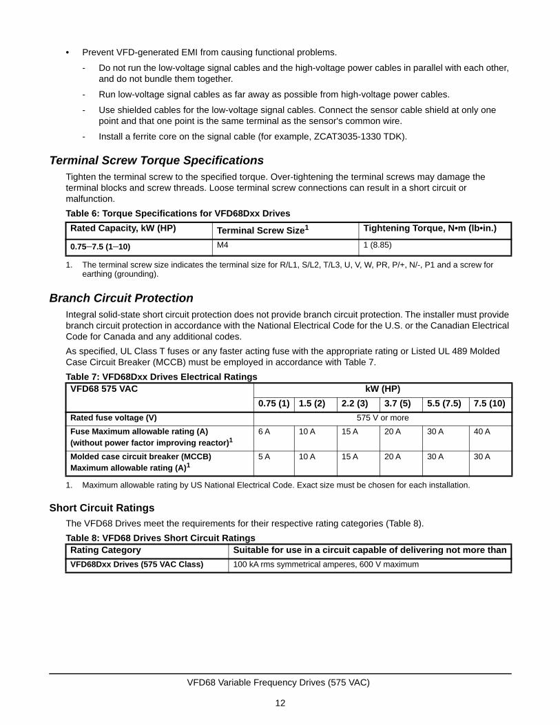
• Prevent VFD-generated EMI from causing functional problems.
- Do not run the low-voltage signal cables and the high-voltage power cables in parallel with each other, and do not bundle them together.
- Run low-voltage signal cables as far away as possible from high-voltage power cables.
- Use shielded cables for the low-voltage signal cables. Connect the sensor cable shield at only one point and that one point is the same terminal as the sensor's common wire.
- Install a ferrite core on the signal cable (for example, ZCAT3035-1330 TDK).
Terminal Screw Torque SpecificationsTighten the terminal screw to the specified torque. Over-tightening the terminal screws may damage the terminal blocks and screw threads. Loose terminal screw connections can result in a short circuit or malfunction.
Branch Circuit ProtectionIntegral solid-state short circuit protection does not provide branch circuit protection. The installer must provide branch circuit protection in accordance with the National Electrical Code for the U.S. or the Canadian Electrical Code for Canada and any additional codes.
As specified, UL Class T fuses or any faster acting fuse with the appropriate rating or Listed UL 489 Molded Case Circuit Breaker (MCCB) must be employed in accordance with Table 7.
Short Circuit Ratings
The VFD68 Drives meet the requirements for their respective rating categories (Table 8).
Table 6: Torque Specifications for VFD68Dxx Drives
Rated Capacity, kW (HP) Terminal Screw Size1
1. The terminal screw size indicates the terminal size for R/L1, S/L2, T/L3, U, V, W, PR, P/+, N/-, P1 and a screw for earthing (grounding).
Tightening Torque, N•m (lb•in.)
0.75–7.5 (1–10) M4 1 (8.85)
Table 7: VFD68Dxx Drives Electrical RatingsVFD68 575 VAC kW (HP)
0.75 (1) 1.5 (2) 2.2 (3) 3.7 (5) 5.5 (7.5) 7.5 (10)
Rated fuse voltage (V) 575 V or more
Fuse Maximum allowable rating (A) (without power factor improving reactor)1
1. Maximum allowable rating by US National Electrical Code. Exact size must be chosen for each installation.
6 A 10 A 15 A 20 A 30 A 40 A
Molded case circuit breaker (MCCB) Maximum allowable rating (A)1
5 A 10 A 15 A 20 A 30 A 30 A
Table 8: VFD68 Drives Short Circuit RatingsRating Category Suitable for use in a circuit capable of delivering not more than
VFD68Dxx Drives (575 VAC Class) 100 kA rms symmetrical amperes, 600 V maximum
VFD68 Variable Frequency Drives (575 VAC)
12
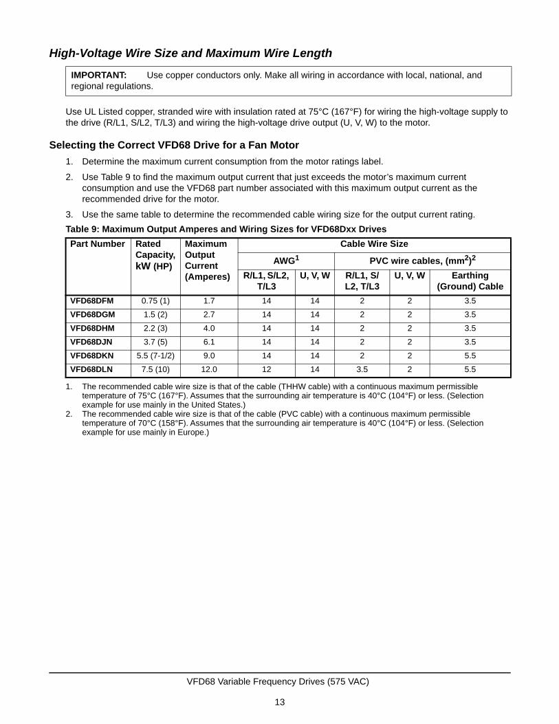
High-Voltage Wire Size and Maximum Wire Length
Use UL Listed copper, stranded wire with insulation rated at 75°C (167°F) for wiring the high-voltage supply to the drive (R/L1, S/L2, T/L3) and wiring the high-voltage drive output (U, V, W) to the motor.
Selecting the Correct VFD68 Drive for a Fan Motor
1. Determine the maximum current consumption from the motor ratings label.
2. Use Table 9 to find the maximum output current that just exceeds the motor’s maximum current consumption and use the VFD68 part number associated with this maximum output current as the recommended drive for the motor.
3. Use the same table to determine the recommended cable wiring size for the output current rating.
IMPORTANT: Use copper conductors only. Make all wiring in accordance with local, national, and regional regulations.
Table 9: Maximum Output Amperes and Wiring Sizes for VFD68Dxx Drives
Part Number Rated Capacity, kW (HP)
Maximum Output Current (Amperes)
Cable Wire Size
AWG1
1. The recommended cable wire size is that of the cable (THHW cable) with a continuous maximum permissible temperature of 75°C (167°F). Assumes that the surrounding air temperature is 40°C (104°F) or less. (Selection example for use mainly in the United States.)
PVC wire cables, (mm2)2
2. The recommended cable wire size is that of the cable (PVC cable) with a continuous maximum permissible temperature of 70°C (158°F). Assumes that the surrounding air temperature is 40°C (104°F) or less. (Selection example for use mainly in Europe.)
R/L1, S/L2, T/L3
U, V, W R/L1, S/L2, T/L3
U, V, W Earthing (Ground) Cable
VFD68DFM 0.75 (1) 1.7 14 14 2 2 3.5
VFD68DGM 1.5 (2) 2.7 14 14 2 2 3.5
VFD68DHM 2.2 (3) 4.0 14 14 2 2 3.5
VFD68DJN 3.7 (5) 6.1 14 14 2 2 3.5
VFD68DKN 5.5 (7-1/2) 9.0 14 14 2 2 5.5
VFD68DLN 7.5 (10) 12.0 12 14 3.5 2 5.5
VFD68 Variable Frequency Drives (575 VAC)
13
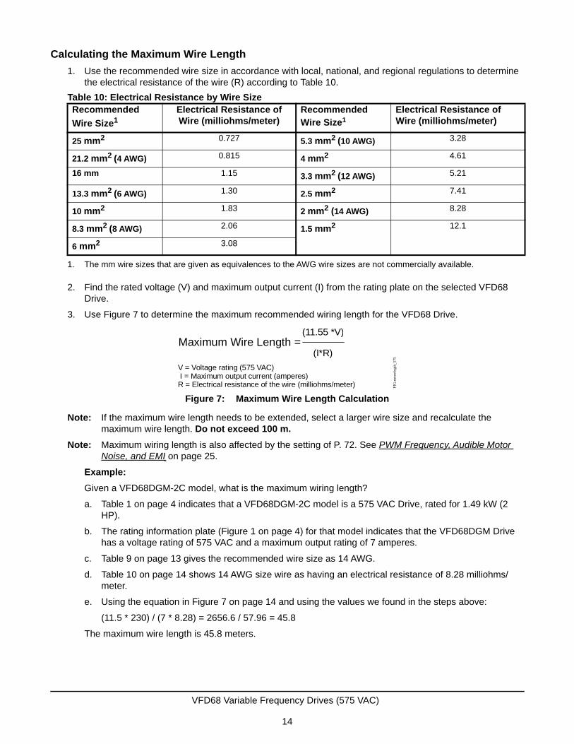
Calculating the Maximum Wire Length
1. Use the recommended wire size in accordance with local, national, and regional regulations to determine the electrical resistance of the wire (R) according to Table 10.
2. Find the rated voltage (V) and maximum output current (I) from the rating plate on the selected VFD68 Drive.
3. Use Figure 7 to determine the maximum recommended wiring length for the VFD68 Drive.
Note: If the maximum wire length needs to be extended, select a larger wire size and recalculate the maximum wire length. Do not exceed 100 m.
Note: Maximum wiring length is also affected by the setting of P. 72. See PWM Frequency, Audible Motor Noise, and EMI on page 25.
Example:
Given a VFD68DGM-2C model, what is the maximum wiring length?
a. Table 1 on page 4 indicates that a VFD68DGM-2C model is a 575 VAC Drive, rated for 1.49 kW (2 HP).
b. The rating information plate (Figure 1 on page 4) for that model indicates that the VFD68DGM Drive has a voltage rating of 575 VAC and a maximum output rating of 7 amperes.
c. Table 9 on page 13 gives the recommended wire size as 14 AWG.
d. Table 10 on page 14 shows 14 AWG size wire as having an electrical resistance of 8.28 milliohms/meter.
e. Using the equation in Figure 7 on page 14 and using the values we found in the steps above:
(11.5 * 230) / (7 * 8.28) = 2656.6 / 57.96 = 45.8
The maximum wire length is 45.8 meters.
Table 10: Electrical Resistance by Wire SizeRecommended
Wire Size1
1. The mm wire sizes that are given as equivalences to the AWG wire sizes are not commercially available.
Electrical Resistance of Wire (milliohms/meter)
Recommended Wire Size1
Electrical Resistance of Wire (milliohms/meter)
25 mm2 0.727 5.3 mm2 (10 AWG) 3.28
21.2 mm2 (4 AWG) 0.815 4 mm2 4.61
16 mm 1.15 3.3 mm2 (12 AWG) 5.21
13.3 mm2 (6 AWG) 1.30 2.5 mm2 7.41
10 mm2 1.83 2 mm2 (14 AWG) 8.28
8.3 mm2 (8 AWG) 2.06 1.5 mm2 12.1
6 mm2 3.08
Figure 7: Maximum Wire Length Calculation
Maximum Wire Length = (11.55 *V)
(I*R)
V = Voltage rating (575 VAC) I = Maximum output current (amperes)R = Electrical resistance of the wire (milliohms/meter) F
IG:m
xwrl
ngth
_575
VFD68 Variable Frequency Drives (575 VAC)
14
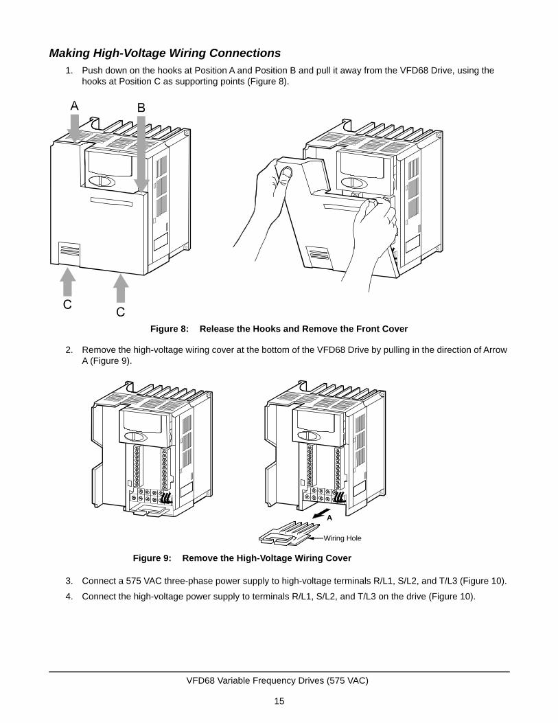
Making High-Voltage Wiring Connections1. Push down on the hooks at Position A and Position B and pull it away from the VFD68 Drive, using the
hooks at Position C as supporting points (Figure 8).
2. Remove the high-voltage wiring cover at the bottom of the VFD68 Drive by pulling in the direction of Arrow A (Figure 9).
3. Connect a 575 VAC three-phase power supply to high-voltage terminals R/L1, S/L2, and T/L3 (Figure 10).
4. Connect the high-voltage power supply to terminals R/L1, S/L2, and T/L3 on the drive (Figure 10).
Figure 8: Release the Hooks and Remove the Front Cover
Figure 9: Remove the High-Voltage Wiring Cover
Wiring Hole
VFD68 Variable Frequency Drives (575 VAC)
15

Note: Use UL-Listed, copper stranded wire with insulation rated at 75°C (167°F) for wiring the high-voltage supply to the drive (R/L1, S/L2, T/L3) and wiring the high-voltage drive output (U, V, W) to the motor.
5. Connect earth ground wiring to the earth ground terminals on the VFD68 Drive and on the motor.
6. Replace the high-voltage wiring cover.
Note: When replacing the high-voltage cover, carefully space and position the leads through the vents or wire slots.
Figure 10: High-Voltage Terminal Block Wiring
Jumper
IM
N/- P/+
R/L1 S/L2 W
VFD68 Variable Frequency Drives (575 VAC)
16
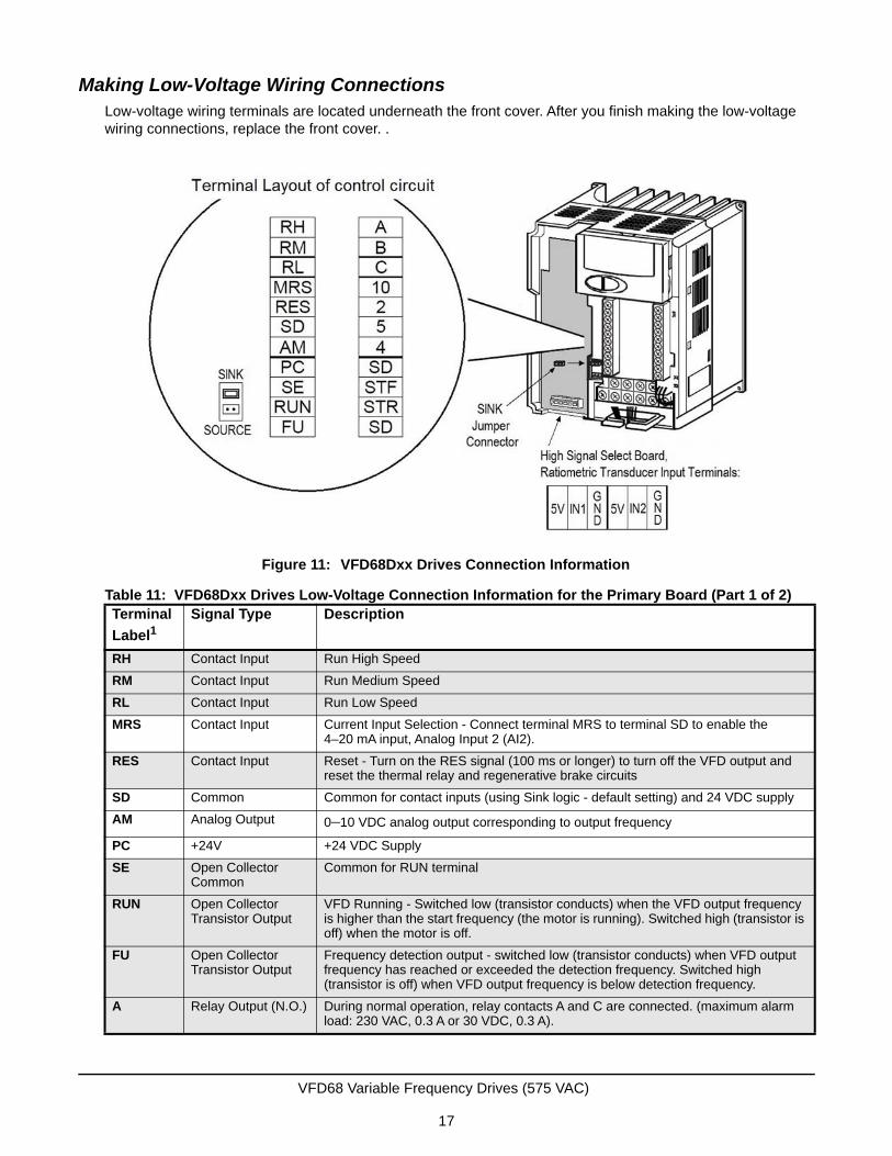
Making Low-Voltage Wiring ConnectionsLow-voltage wiring terminals are located underneath the front cover. After you finish making the low-voltage wiring connections, replace the front cover. .
Table 11: VFD68Dxx Drives Low-Voltage Connection Information for the Primary Board (Part 1 of 2)Terminal
Label1Signal Type Description
RH Contact Input Run High Speed
RM Contact Input Run Medium Speed
RL Contact Input Run Low Speed
MRS Contact Input Current Input Selection - Connect terminal MRS to terminal SD to enable the 4–20 mA input, Analog Input 2 (AI2).
RES Contact Input Reset - Turn on the RES signal (100 ms or longer) to turn off the VFD output and reset the thermal relay and regenerative brake circuits
SD Common Common for contact inputs (using Sink logic - default setting) and 24 VDC supply
AM Analog Output 0–10 VDC analog output corresponding to output frequency
PC +24V +24 VDC Supply
SE Open Collector Common
Common for RUN terminal
RUN Open Collector Transistor Output
VFD Running - Switched low (transistor conducts) when the VFD output frequency is higher than the start frequency (the motor is running). Switched high (transistor is off) when the motor is off.
FU Open Collector Transistor Output
Frequency detection output - switched low (transistor conducts) when VFD output frequency has reached or exceeded the detection frequency. Switched high (transistor is off) when VFD output frequency is below detection frequency.
A Relay Output (N.O.) During normal operation, relay contacts A and C are connected. (maximum alarm load: 230 VAC, 0.3 A or 30 VDC, 0.3 A).
Figure 11: VFD68Dxx Drives Connection Information
VFD68 Variable Frequency Drives (575 VAC)
17
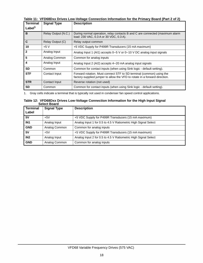
B Relay Output (N.C.) During normal operation, relay contacts B and C are connected (maximum alarm load: 230 VAC, 0.3 A or 30 VDC, 0.3 A).
C Relay Output (C) Relay output common
10 +5 V +5 VDC Supply for P499R Transducers (15 mA maximum)
2 Analog Input Analog Input 1 (AI1) accepts 0–5 V or 0–10 V DC analog input signals
5 Analog Common Common for analog inputs
4 Analog Input Analog Input 2 (AI2) accepts 4–20 mA analog input signals
SD Common Common for contact inputs (when using Sink logic - default setting).
STF Contact Input Forward rotation. Must connect STF to SD terminal (common) using the factory-supplied jumper to allow the VFD to rotate in a forward direction.
STR Contact Input Reverse rotation (not used)
SD Common Common for contact inputs (when using Sink logic - default setting).
1. Gray cells indicate a terminal that is typically not used in condenser fan speed control applications.
Table 12: VFD68Dxx Drives Low-Voltage Connection Information for the High Input Signal Select Board
Terminal Label
Signal Type Description
5V +5V +5 VDC Supply for P499R Transducers (15 mA maximum)
IN1 Analog Input Analog Input 1 for 0.5 to 4.5 V Ratiometric High Signal Select
GND Analog Common Common for analog inputs
5V +5V +5 VDC Supply for P499R Transducers (15 mA maximum)
IN2 Analog Input Analog Input 2 for 0.5 to 4.5 V Ratiometric High Signal Select
GND Analog Common Common for analog inputs
Table 11: VFD68Dxx Drives Low-Voltage Connection Information for the Primary Board (Part 2 of 2)Terminal
Label1Signal Type Description
VFD68 Variable Frequency Drives (575 VAC)
18
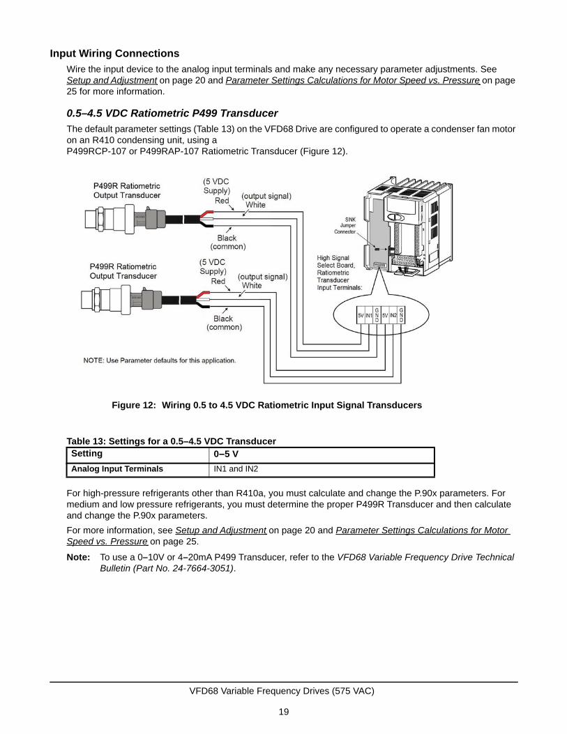
Input Wiring Connections
Wire the input device to the analog input terminals and make any necessary parameter adjustments. See Setup and Adjustment on page 20 and Parameter Settings Calculations for Motor Speed vs. Pressure on page 25 for more information.
0.5–4.5 VDC Ratiometric P499 Transducer
The default parameter settings (Table 13) on the VFD68 Drive are configured to operate a condenser fan motor on an R410 condensing unit, using a P499RCP-107 or P499RAP-107 Ratiometric Transducer (Figure 12).
For high-pressure refrigerants other than R410a, you must calculate and change the P.90x parameters. For medium and low pressure refrigerants, you must determine the proper P499R Transducer and then calculate and change the P.90x parameters.
For more information, see Setup and Adjustment on page 20 and Parameter Settings Calculations for Motor Speed vs. Pressure on page 25.
Note: To use a 0–10V or 4–20mA P499 Transducer, refer to the VFD68 Variable Frequency Drive Technical Bulletin (Part No. 24-7664-3051).
Table 13: Settings for a 0.5–4.5 VDC TransducerSetting 0–5 V
Analog Input Terminals IN1 and IN2
Figure 12: Wiring 0.5 to 4.5 VDC Ratiometric Input Signal Transducers
VFD68 Variable Frequency Drives (575 VAC)
19
Setup and Adjustment
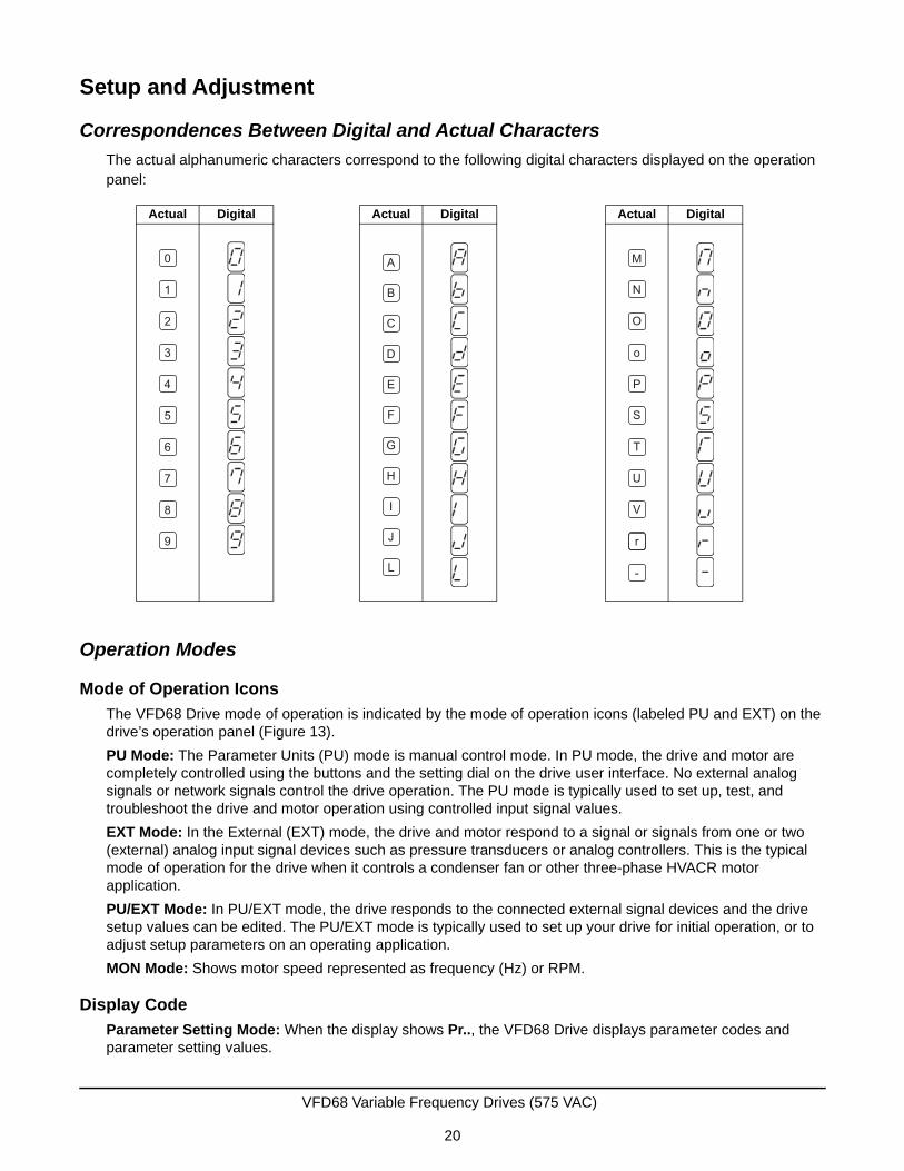
Correspondences Between Digital and Actual Characters
The actual alphanumeric characters correspond to the following digital characters displayed on the operation panel:
Operation Modes
Mode of Operation Icons
The VFD68 Drive mode of operation is indicated by the mode of operation icons (labeled PU and EXT) on the drive’s operation panel (Figure 13).
PU Mode: The Parameter Units (PU) mode is manual control mode. In PU mode, the drive and motor are completely controlled using the buttons and the setting dial on the drive user interface. No external analog signals or network signals control the drive operation. The PU mode is typically used to set up, test, and troubleshoot the drive and motor operation using controlled input signal values.
EXT Mode: In the External (EXT) mode, the drive and motor respond to a signal or signals from one or two (external) analog input signal devices such as pressure transducers or analog controllers. This is the typical mode of operation for the drive when it controls a condenser fan or other three-phase HVACR motor application.
PU/EXT Mode: In PU/EXT mode, the drive responds to the connected external signal devices and the drive setup values can be edited. The PU/EXT mode is typically used to set up your drive for initial operation, or to adjust setup parameters on an operating application.
MON Mode: Shows motor speed represented as frequency (Hz) or RPM.
Display Code
Parameter Setting Mode: When the display shows Pr.., the VFD68 Drive displays parameter codes and parameter setting values.
Actual Digital
0
1
2
3
4
5
6
7
8
9
Actual Digital
A
B
C
E
F
G
H
I
J
L
D
Actual Digital
M
N
O
o
P
T
U
V
r
-
S
VFD68 Variable Frequency Drives (575 VAC)
20
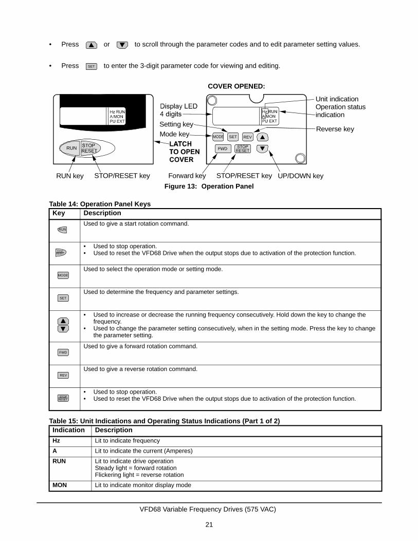
• Press or to scroll through the parameter codes and to edit parameter setting values.
• Press to enter the 3-digit parameter code for viewing and editing.
Table 14: Operation Panel KeysKey Description
Used to give a start rotation command.
• Used to stop operation.• Used to reset the VFD68 Drive when the output stops due to activation of the protection function.
Used to select the operation mode or setting mode.
Used to determine the frequency and parameter settings.
• Used to increase or decrease the running frequency consecutively. Hold down the key to change the frequency.
• Used to change the parameter setting consecutively, when in the setting mode. Press the key to change the parameter setting.
Used to give a forward rotation command.
Used to give a reverse rotation command.
• Used to stop operation.• Used to reset the VFD68 Drive when the output stops due to activation of the protection function.
Table 15: Unit Indications and Operating Status Indications (Part 1 of 2)Indication Description
Hz Lit to indicate frequency
A Lit to indicate the current (Amperes)
RUN Lit to indicate drive operationSteady light = forward rotationFlickering light = reverse rotation
MON Lit to indicate monitor display mode
SET
Figure 13: Operation Panel
Unit indicationOperation statusindication
Reverse keySetting key
Mode key
RUN key STOP/RESET key Forward key STOP/RESET key UP/DOWN key
COVER OPENED:
REVSET
RESETRUN
RUN
STOPRESET
MODE
SET
FWD
REV
STOPRESET
VFD68 Variable Frequency Drives (575 VAC)
21
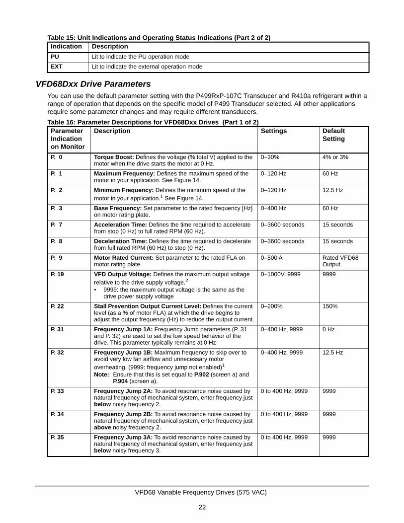
VFD68Dxx Drive ParametersYou can use the default parameter setting with the P499RxP-107C Transducer and R410a refrigerant within a range of operation that depends on the specific model of P499 Transducer selected. All other applications require some parameter changes and may require different transducers.
PU Lit to indicate the PU operation mode
EXT Lit to indicate the external operation mode
Table 16: Parameter Descriptions for VFD68Dxx Drives (Part 1 of 2)ParameterIndication on Monitor
Description Settings Default Setting
P. 0 Torque Boost: Defines the voltage (% total V) applied to the motor when the drive starts the motor at 0 Hz.
0–30% 4% or 3%
P. 1 Maximum Frequency: Defines the maximum speed of the motor in your application. See Figure 14.
0–120 Hz 60 Hz
P. 2 Minimum Frequency: Defines the minimum speed of the motor in your application.1 See Figure 14.
0–120 Hz 12.5 Hz
P. 3 Base Frequency: Set parameter to the rated frequency [Hz] on motor rating plate.
0–400 Hz 60 Hz
P. 7 Acceleration Time: Defines the time required to accelerate from stop (0 Hz) to full rated RPM (60 Hz).
0–3600 seconds 15 seconds
P. 8 Deceleration Time: Defines the time required to decelerate from full rated RPM (60 Hz) to stop (0 Hz).
0–3600 seconds 15 seconds
P. 9 Motor Rated Current: Set parameter to the rated FLA on motor rating plate.
0–500 A Rated VFD68 Output
P. 19 VFD Output Voltage: Defines the maximum output voltage relative to the drive supply voltage.2
• 9999: the maximum output voltage is the same as the drive power supply voltage
0–1000V, 9999 9999
P. 22 Stall Prevention Output Current Level: Defines the current level (as a % of motor FLA) at which the drive begins to adjust the output frequency (Hz) to reduce the output current.
0–200% 150%
P. 31 Frequency Jump 1A: Frequency Jump parameters (P. 31 and P. 32) are used to set the low speed behavior of the drive. This parameter typically remains at 0 Hz
0–400 Hz, 9999 0 Hz
P. 32 Frequency Jump 1B: Maximum frequency to skip over to avoid very low fan airflow and unnecessary motor overheating. (9999: frequency jump not enabled)1
Note: Ensure that this is set equal to P.902 (screen a) and P.904 (screen a).
0–400 Hz, 9999 12.5 Hz
P. 33 Frequency Jump 2A: To avoid resonance noise caused by natural frequency of mechanical system, enter frequency just below noisy frequency 2.
0 to 400 Hz, 9999 9999
P. 34 Frequency Jump 2B: To avoid resonance noise caused by natural frequency of mechanical system, enter frequency just above noisy frequency 2.
0 to 400 Hz, 9999 9999
P. 35 Frequency Jump 3A: To avoid resonance noise caused by natural frequency of mechanical system, enter frequency just below noisy frequency 3.
0 to 400 Hz, 9999 9999
Table 15: Unit Indications and Operating Status Indications (Part 2 of 2)Indication Description
VFD68 Variable Frequency Drives (575 VAC)
22
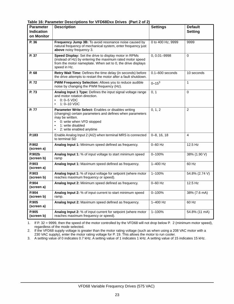
P. 36 Frequency Jump 3B: To avoid resonance noise caused by natural frequency of mechanical system, enter frequency just above noisy frequency 3.
0 to 400 Hz, 9999 9999
P. 37 Speed Display: Set the drive to display motor in RPMs (instead of Hz) by entering the maximum rated motor speed from the motor nameplate. When set to 0, the drive displays speed in Hz.
0, 0.01–9998 0
P. 68 Retry Wait Time: Defines the time delay (in seconds) before the drive attempts to restart the motor after a fault shutdown.
0.1–600 seconds 10 seconds
P. 72 PWM Frequency Selection: Allows you to reduce audible noise by changing the PWM frequency (Hz).
0–153 1
P. 73 Analog Input 1 Type: Defines the input signal voltage range and motor rotation direction. • 0: 0–5 VDC • 1: 0–10 VDC
0, 1 0
P. 77 Parameter Write Select: Enables or disables writing (changing) certain parameters and defines when parameters may be written. • 0: write when VFD stopped • 1: write disabled• 2: write enabled anytime
0, 1, 2 2
P.183 Enable Analog Input 2 (AI2) when terminal MRS is connected to terminal SD
0–8, 16, 18 4
P.902(screen a)
Analog Input 1: Minimum speed defined as frequency. 0–60 Hz 12.5 Hz
P.902b(screen b)
Analog Input 1: % of input voltage to start minimum speed ramp
0–100% 38% (1.90 V)
P.903(screen a)
Analog Input 1: Maximum speed defined as frequency. 1–400 Hz 60 Hz
P.903(screen b)
Analog Input 1: % of input voltage for setpoint (where motor reaches maximum frequency or speed).
1–100% 54.8% (2.74 V)
P.904(screen a)
Analog Input 2: Minimum speed defined as frequency. 0–60 Hz 12.5 Hz
P.904(screen b)
Analog Input 2: % of input current to start minimum speed ramp.
0–100% 38% (7.6 mA)
P.905 (screen a)
Analog Input 2: Maximum speed defined as frequency. 1–400 Hz 60 Hz
P.905(screen b)
Analog Input 2: % of input current for setpoint (where motor reaches maximum frequency or speed).
1–100% 54.8% (11 mA)
1. If P. 32 = 9999, then the speed of the motor controlled by the VFD68 will not drop below P. 2 (minimum motor speed), regardless of the mode selected.
2. If the VFD68 supply voltage is greater than the motor rating voltage (such as when using a 208 VAC motor with a 230 VAC supply), enter the motor rating voltage for P. 19. This allows the motor to run cooler.
3. A setting value of 0 indicates 0.7 kHz. A setting value of 1 indicates 1 kHz. A setting value of 15 indicates 15 kHz.
Table 16: Parameter Descriptions for VFD68Dxx Drives (Part 2 of 2)ParameterIndication on Monitor
Description Settings Default Setting
VFD68 Variable Frequency Drives (575 VAC)
23
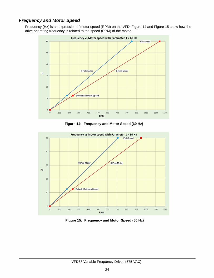
Frequency and Motor SpeedFrequency (Hz) is an expression of motor speed (RPM) on the VFD. Figure 14 and Figure 15 show how the drive operating frequency is related to the speed (RPM) of the motor.
Figure 14: Frequency and Motor Speed (60 Hz)
Figure 15: Frequency and Motor Speed (50 Hz)
VFD68 Variable Frequency Drives (575 VAC)
24
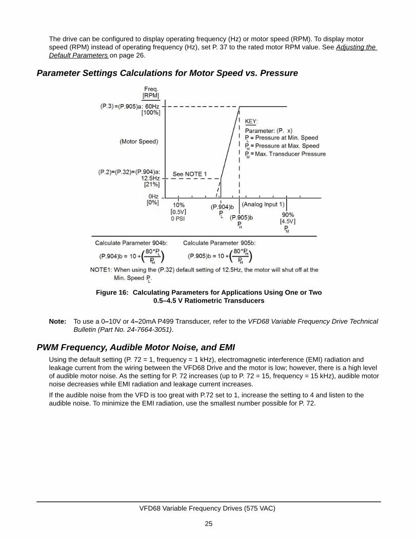
The drive can be configured to display operating frequency (Hz) or motor speed (RPM). To display motor speed (RPM) instead of operating frequency (Hz), set P. 37 to the rated motor RPM value. See Adjusting the Default Parameters on page 26.
Parameter Settings Calculations for Motor Speed vs. Pressure
Note: To use a 0–10V or 4–20mA P499 Transducer, refer to the VFD68 Variable Frequency Drive Technical Bulletin (Part No. 24-7664-3051).
PWM Frequency, Audible Motor Noise, and EMIUsing the default setting (P. 72 = 1, frequency = 1 kHz), electromagnetic interference (EMI) radiation and leakage current from the wiring between the VFD68 Drive and the motor is low; however, there is a high level of audible motor noise. As the setting for P. 72 increases (up to P. 72 = 15, frequency = 15 kHz), audible motor noise decreases while EMI radiation and leakage current increases.
If the audible noise from the VFD is too great with P.72 set to 1, increase the setting to 4 and listen to the audible noise. To minimize the EMI radiation, use the smallest number possible for P. 72.
Figure 16: Calculating Parameters for Applications Using One or Two 0.5–4.5 V Ratiometric Transducers
VFD68 Variable Frequency Drives (575 VAC)
25
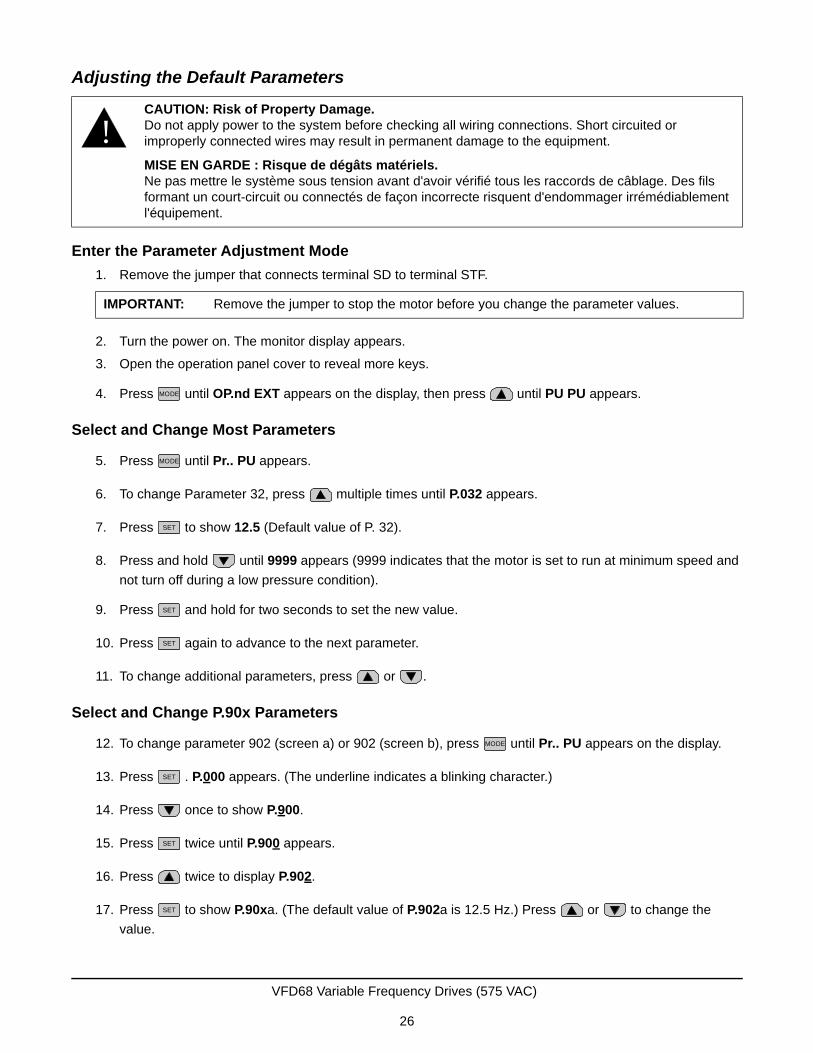
Adjusting the Default Parameters
Enter the Parameter Adjustment Mode
1. Remove the jumper that connects terminal SD to terminal STF.
2. Turn the power on. The monitor display appears.
3. Open the operation panel cover to reveal more keys.
4. Press until OP.nd EXT appears on the display, then press until PU PU appears.
Select and Change Most Parameters
5. Press until Pr.. PU appears.
6. To change Parameter 32, press multiple times until P.032 appears.
7. Press to show 12.5 (Default value of P. 32).
8. Press and hold until 9999 appears (9999 indicates that the motor is set to run at minimum speed and
not turn off during a low pressure condition).
9. Press and hold for two seconds to set the new value.
10. Press again to advance to the next parameter.
11. To change additional parameters, press or .
Select and Change P.90x Parameters
12. To change parameter 902 (screen a) or 902 (screen b), press until Pr.. PU appears on the display.
13. Press . P.000 appears. (The underline indicates a blinking character.)
14. Press once to show P.900.
15. Press twice until P.900 appears.
16. Press twice to display P.902.
17. Press to show P.90xa. (The default value of P.902a is 12.5 Hz.) Press or to change the
value.
!CAUTION: Risk of Property Damage.Do not apply power to the system before checking all wiring connections. Short circuited or improperly connected wires may result in permanent damage to the equipment.
MISE EN GARDE : Risque de dégâts matériels.Ne pas mettre le système sous tension avant d'avoir vérifié tous les raccords de câblage. Des fils formant un court-circuit ou connectés de façon incorrecte risquent d'endommager irrémédiablement l'équipement.
IMPORTANT: Remove the jumper to stop the motor before you change the parameter values.
MODE
MODE
SET
SET
SET
MODE
SET
SET
SET
VFD68 Variable Frequency Drives (575 VAC)
26
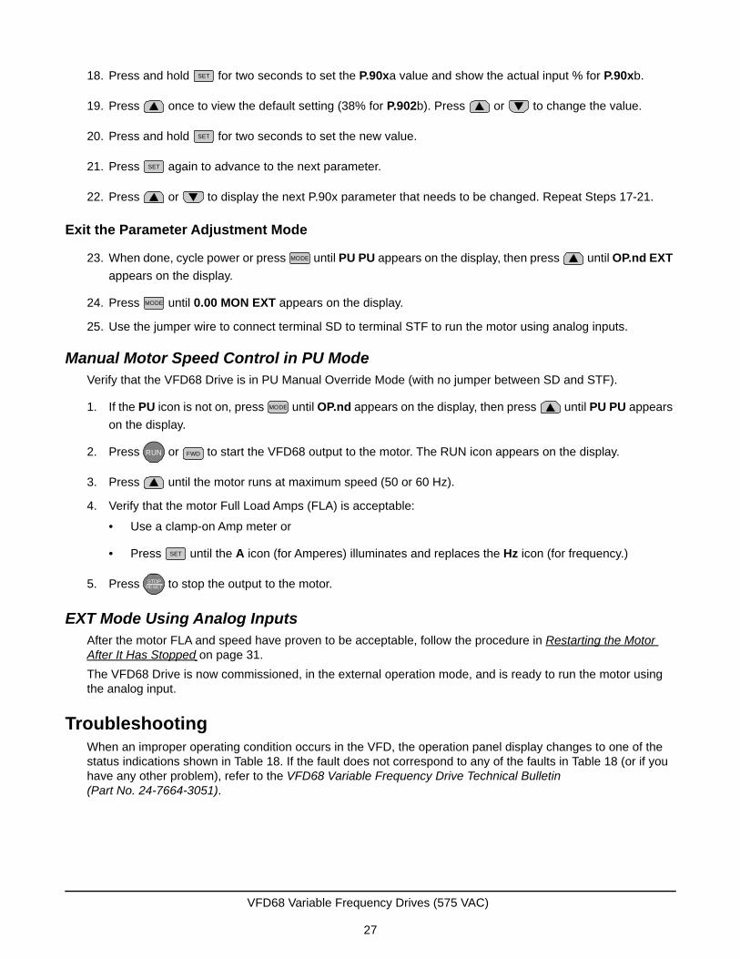
18. Press and hold for two seconds to set the P.90xa value and show the actual input % for P.90xb.
19. Press once to view the default setting (38% for P.902b). Press or to change the value.
20. Press and hold for two seconds to set the new value.
21. Press again to advance to the next parameter.
22. Press or to display the next P.90x parameter that needs to be changed. Repeat Steps 17-21.
Exit the Parameter Adjustment Mode
23. When done, cycle power or press until PU PU appears on the display, then press until OP.nd EXT
appears on the display.
24. Press until 0.00 MON EXT appears on the display.
25. Use the jumper wire to connect terminal SD to terminal STF to run the motor using analog inputs.
Manual Motor Speed Control in PU ModeVerify that the VFD68 Drive is in PU Manual Override Mode (with no jumper between SD and STF).
1. If the PU icon is not on, press until OP.nd appears on the display, then press until PU PU appears
on the display.
2. Press or to start the VFD68 output to the motor. The RUN icon appears on the display.
3. Press until the motor runs at maximum speed (50 or 60 Hz).
4. Verify that the motor Full Load Amps (FLA) is acceptable:
• Use a clamp-on Amp meter or
• Press until the A icon (for Amperes) illuminates and replaces the Hz icon (for frequency.)
5. Press to stop the output to the motor.
EXT Mode Using Analog InputsAfter the motor FLA and speed have proven to be acceptable, follow the procedure in Restarting the Motor After It Has Stopped on page 31.
The VFD68 Drive is now commissioned, in the external operation mode, and is ready to run the motor using the analog input.
TroubleshootingWhen an improper operating condition occurs in the VFD, the operation panel display changes to one of the status indications shown in Table 18. If the fault does not correspond to any of the faults in Table 18 (or if you have any other problem), refer to the VFD68 Variable Frequency Drive Technical Bulletin (Part No. 24-7664-3051).
SET
SET
SET
MODE
MODE
MODE
RUN FWD
SET
STOPRESETSTOP
RESET
VFD68 Variable Frequency Drives (575 VAC)
27
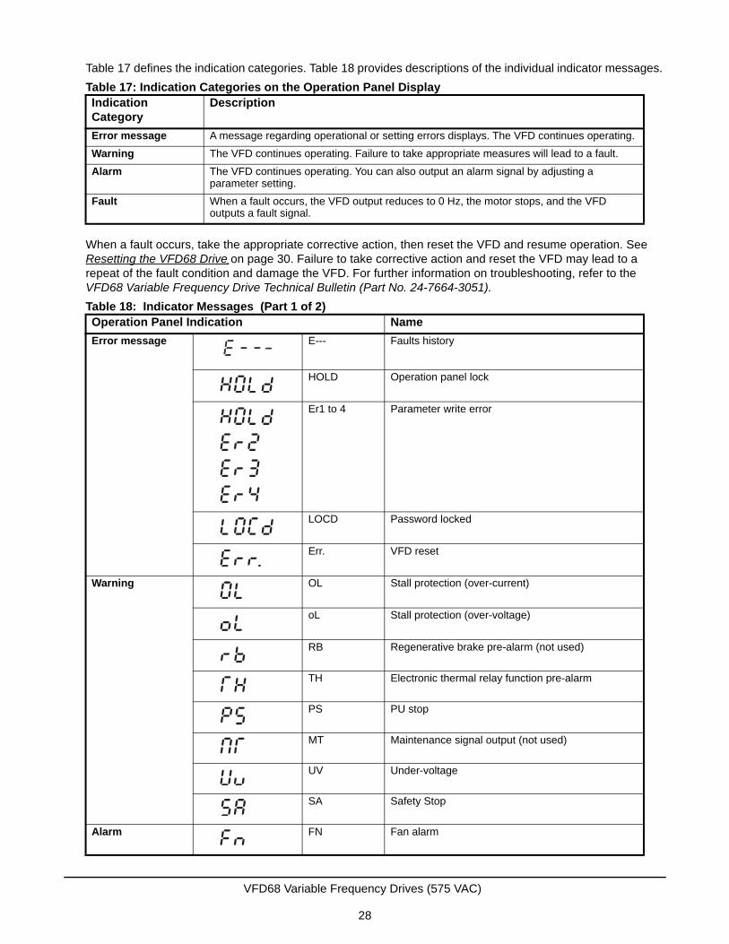
Table 17 defines the indication categories. Table 18 provides descriptions of the individual indicator messages.
When a fault occurs, take the appropriate corrective action, then reset the VFD and resume operation. See Resetting the VFD68 Drive on page 30. Failure to take corrective action and reset the VFD may lead to a repeat of the fault condition and damage the VFD. For further information on troubleshooting, refer to the VFD68 Variable Frequency Drive Technical Bulletin (Part No. 24-7664-3051).
Table 17: Indication Categories on the Operation Panel DisplayIndication Category
Description
Error message A message regarding operational or setting errors displays. The VFD continues operating.
Warning The VFD continues operating. Failure to take appropriate measures will lead to a fault.
Alarm The VFD continues operating. You can also output an alarm signal by adjusting a parameter setting.
Fault When a fault occurs, the VFD output reduces to 0 Hz, the motor stops, and the VFD outputs a fault signal.
Table 18: Indicator Messages (Part 1 of 2)Operation Panel Indication Name
Error message E--- Faults history
HOLD Operation panel lock
Er1 to 4 Parameter write error
LOCD Password locked
Err. VFD reset
Warning OL Stall protection (over-current)
oL Stall protection (over-voltage)
RB Regenerative brake pre-alarm (not used)
TH Electronic thermal relay function pre-alarm
PS PU stop
MT Maintenance signal output (not used)
UV Under-voltage
SA Safety Stop
Alarm FN Fan alarm
VFD68 Variable Frequency Drives (575 VAC)
28
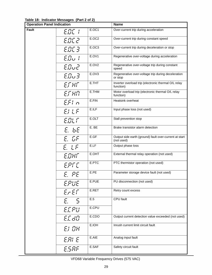
Fault E.OC1 Over-current trip during acceleration
E.OC2 Over-current trip during constant speed
E.OC3 Over-current trip during deceleration or stop
E.OV1 Regenerative over-voltage during acceleration
E.OV2 Regenerative over-voltage trip during constant speed
E.OV3 Regenerative over-voltage trip during deceleration or stop
E.THT Inverter overload trip (electronic thermal O/L relay function)
E.THM Motor overload trip (electronic thermal O/L relay function)
E.FIN Heatsink overheat
E.ILF Input phase loss (not used)
E.OLT Stall prevention stop
E. BE Brake transistor alarm detection
E.GF Output side earth (ground) fault over-current at start (not used)
E.LF Output phase loss
E.OHT External thermal relay operation (not used)
E.PTC PTC thermistor operation (not used)
E.PE Parameter storage device fault (not used)
E.PUE PU disconnection (not used)
E.RET Retry count excess
E.5 CPU fault
E.CPU
E.CDO Output current detection value exceeded (not used)
E.IOH Inrush current limit circuit fault
E.AIE Analog input fault
E.SAF Safety circuit fault
Table 18: Indicator Messages (Part 2 of 2)Operation Panel Indication Name
VFD68 Variable Frequency Drives (575 VAC)
29
Resetting the VFD68 Drive
If the motor stops due to a fault, you can reset the VFD by using either of the following two methods.
Reset Option 1
1. Remove the jumper that connects terminal SD to terminal STF before clearing the fault.
2. Using the operation panel, press to reset the VFD.
3. Go to Restarting the Motor After It Has Stopped.
Reset Option 2
1. Remove the jumper that connects terminal SD to terminal STF before clearing the fault.
2. Disconnect power from the drive. After the indicator of the operation panel turns OFF, reinstall the jumper that connects terminal SD to terminal STF.
3. Reconnect power to the drive.
Manually Stopping the Motor
You can stop the motor while the VFD68 Drive is in any mode (PU, EXT, or NET) by pressing . When you
press , the drive monitor displays PS (PU Stop Warning) and then performs a controlled shutdown of the
motor.
!WARNING: Risk of Personal Injury.Before you reset the VFD68 Drive, verify that all persons are clear of the controlled equipment. Resetting the VFD68 Drive may immediately start the controlled equipment, and failure to verify that all persons are clear of the controlled equipment before resetting the VFD68 Drive may result in severe personal injury or death.
AVERTISSEMENT: Risque de blessure.Avant de réinitialiser le VFD68 Drive, assurez-vous qu'aucune personne n'est à proximité de l'équipement. La réinitialisation du VFD68 Drive peut faire redémarrer l'équipement contrôlé immédiatement et le non-respect de cette précaution pourrait entraîner des blessures graves, voire mortelles.
IMPORTANT: To prevent the motor from starting immediately after a fault reset, remove the jumper that connects terminal SD to terminal STF before clearing the reset.
STOPRESETSTOP
RESET
STOPRESETSTOP
RESET
STOPRESETSTOP
RESET
VFD68 Variable Frequency Drives (575 VAC)
30
Restarting the Motor After It Has StoppedTo restart the motor after a controlled stop, disconnect the supply power from the drive for at least 30 seconds and then reconnect the supply power to the drive.
If it is not easy to disconnect the supply power from the drive, follow these steps:
1. Disconnect the jumper between the SD and STF terminals on the low-voltage terminal blocks.
2. Verify that the SINK/SOURCE jumper to the left of the low voltage terminal blocks (Figure 11) is set to SINK.
3. Press until PU PU appears on the display.
4. Press until OP.nd EXT appears on the display.
5. Press until 0.00 MON EXT appears on the display.
6. Reconnect the jumper between the SD and STF terminals.
The VFD68 is now commissioned, is in the external operation mode, and is ready to run the motor using the analog inputs.
7. Press to return to monitor mode. 0.00 MON PU appears on the screen.
MODE
MODE
MODE
VFD68 Variable Frequency Drives (575 VAC)
31
recommended
e appropriate wire
4421;
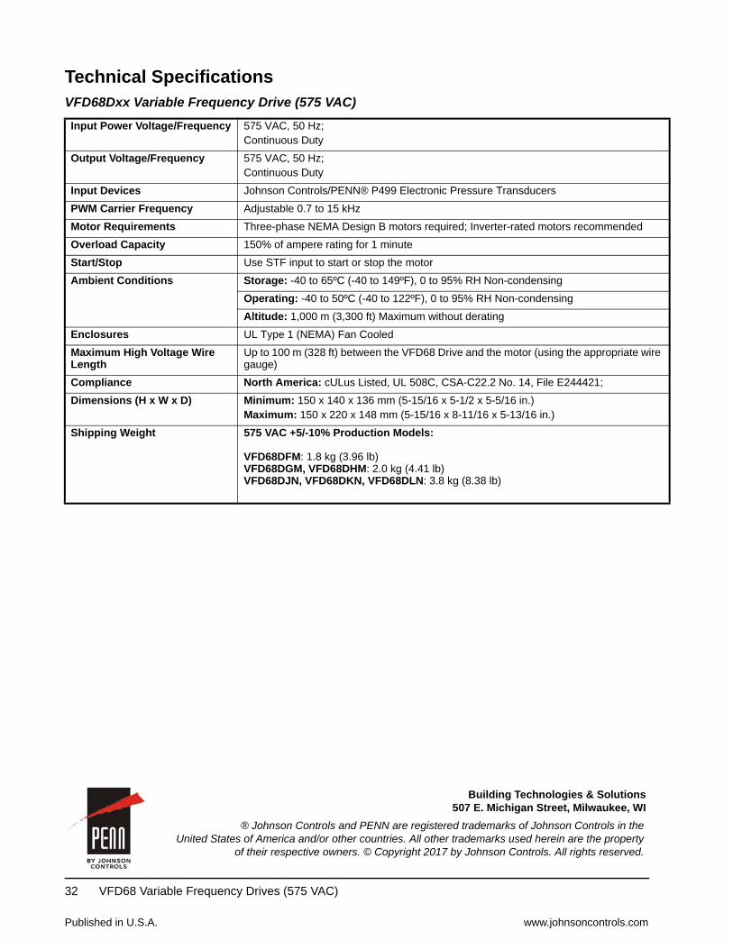
Technical SpecificationsVFD68Dxx Variable Frequency Drive (575 VAC)
Input Power Voltage/Frequency 575 VAC, 50 Hz;Continuous Duty
Output Voltage/Frequency 575 VAC, 50 Hz;Continuous Duty
Input Devices Johnson Controls/PENN® P499 Electronic Pressure Transducers
PWM Carrier Frequency Adjustable 0.7 to 15 kHz
Motor Requirements Three-phase NEMA Design B motors required; Inverter-rated motors
Overload Capacity 150% of ampere rating for 1 minute
Start/Stop Use STF input to start or stop the motor
Ambient Conditions Storage: -40 to 65ºC (-40 to 149ºF), 0 to 95% RH Non-condensing
Operating: -40 to 50ºC (-40 to 122ºF), 0 to 95% RH Non-condensing
Altitude: 1,000 m (3,300 ft) Maximum without derating
Enclosures UL Type 1 (NEMA) Fan Cooled
Maximum High Voltage Wire Length
Up to 100 m (328 ft) between the VFD68 Drive and the motor (using thgauge)
Compliance North America: cULus Listed, UL 508C, CSA-C22.2 No. 14, File E24
Dimensions (H x W x D) Minimum: 150 x 140 x 136 mm (5-15/16 x 5-1/2 x 5-5/16 in.)Maximum: 150 x 220 x 148 mm (5-15/16 x 8-11/16 x 5-13/16 in.)
Shipping Weight 575 VAC +5/-10% Production Models:
VFD68DFM: 1.8 kg (3.96 lb)VFD68DGM, VFD68DHM: 2.0 kg (4.41 lb)VFD68DJN, VFD68DKN, VFD68DLN: 3.8 kg (8.38 lb)
Published in U.S.A. www.johnsoncontrols.com
VFD68 Variable Frequency Drives (575 VAC) 32
Metasys® and Johnson Controls® are registered trademarks of Johnson Controls, Inc.All other marks herein are the marks of their respective owners. © 2011 Johnson Controls, Inc.
Building Efficiency507 E. Michigan Street, Milwaukee, WI 53202® Johnson Controls and PENN are registered trademarks of Johnson Controls in the
United States of America and/or other countries. All other trademarks used herein are the propertyof their respective owners. © Copyright 2017 by Johnson Controls. All rights reserved.
Building Technologies & Solutions507 E. Michigan Street, Milwaukee, WI