vgp351 – week 6 - freedesktop.orgidr/2009q2-vgp352...anyone who has seen a cartoon or a comic book...
TRANSCRIPT

© Copyright Ian D. Romanick 2009
13-May-2009
VGP351 – Week 6
⇨ Agenda: Fins-and-shells fur Nonphotorealistic Rendering
Cel shading Gooch technical illustration

© Copyright Ian D. Romanick 2009
13-May-2009
Volumetric Fur
⇨ Close-up, fur appears as a volumetric effect⇨ Kajika and Kay presented an algorithm at
SIGGRAPH '89 implementing fur via 3D textures Volumetric textures are very memory intensive Kajika and Kay's model involves several
computationally expensive steps
⇨ Not practical for real-time There has to be a different way!

© Copyright Ian D. Romanick 2009
13-May-2009
Shells and Fins
⇨ Instead of a 3D texture, fur can be implemented with a “stack” of 2D textures
Each layer in the stack represents the fur at a different depth
Draw each layer in a progressively larger “shell” around the original object geometry

© Copyright Ian D. Romanick 2009
13-May-2009
Shells and Fins
⇨ Drawing loop: Draw base object with inner-most (call it level 0) fur
texture Disable alpha blending Enable z-testing Enable z-writing
Draw base geometry moved out some small step along the normals
Enable alpha blending Enable z-testing Disable z-writing

© Copyright Ian D. Romanick 2009
13-May-2009
Shells and Fins
⇨ But this looks bad along the silhouette

© Copyright Ian D. Romanick 2009
13-May-2009
Shells and Fins
⇨ Add fin geometry to each polygon Create fin textures to look like side-on view of fur Draw fin after drawing all shells
Enable alpha blending Enable z-testing Disable z-writing

© Copyright Ian D. Romanick 2009
13-May-2009
Shells and Fins
⇨ Generate fin geometry in the vertex shader: Draw each vertex twice
Once with w = 0 Once with w = 1
Use the w value to determine whether or not to extrude the vertex in the normal direction
Draw the vertices as two triangles: One with vertices 0, 1, 1 The other with vertices 1, 0, 0

© Copyright Ian D. Romanick 2009
13-May-2009
Shells and Fins
⇨ But this looks bad in non-silhouette areas

© Copyright Ian D. Romanick 2009
13-May-2009
Shells and Fins
⇨ Gradually blend in fins as they approach the silhouette
⇨ We don't really have a fin normal...what to do?
fin=max 0,2∣cos V ,N fin∣−1

© Copyright Ian D. Romanick 2009
13-May-2009
Shells and Fins
⇨ Gradually blend in fins as they approach the silhouette
⇨ We don't really have a fin normal...what to do? The surface's normal is the fin's tangent
fin=max 0,2∣cos V ,N fin∣−1
fin=max 0,2∣sin V ,N surface∣−1

© Copyright Ian D. Romanick 2009
13-May-2009
Shells and Fins
⇨ Alpha blended fins

© Copyright Ian D. Romanick 2009
13-May-2009
Lighting Shells and Fins
⇨ Use the surface normal as the direction of the hair
Pd and P
s are diffuse and specular exponents
Similar to Goldman's fakefur lighting model
⇨ A little trig-identity love gets us:
K=K d sin N surface , LPdK s sin N surface , H
Ps
K = K d 1−cosN surface , LPd /2K s1−cos N surface , H
Ps/2
K = K d 1−N surface⋅LPd /2K s1−N surface⋅H
Ps/2
© Copyright Ian D. Romanick 2009
13-May-2009
Lighting Shells and Fins
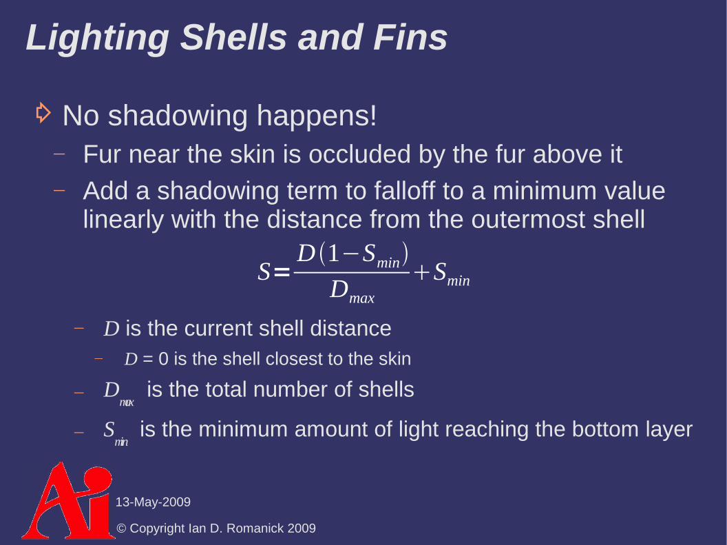
⇨ No shadowing happens! Fur near the skin is occluded by the fur above it Add a shadowing term to falloff to a minimum value
linearly with the distance from the outermost shell
D is the current shell distance D = 0 is the shell closest to the skin
Dmax
is the total number of shells
Smin
is the minimum amount of light reaching the bottom layer
S=D 1−Smin
DmaxSmin

© Copyright Ian D. Romanick 2009
13-May-2009
References
Sheppard, G. Real-Time Rendering of Fur. Honors Thesis, Univ. of Sheffield. 2004. http://www.gamasutra.com/education/theses/20051028/sheppard_01.shtml
Thorough overview of the various real-time fur methods.
Tariq, S. Fur (using Shells and Fins). Nvidia White Paper, Number WP-03021-001_v01. February 2007.http://developer.download.nvidia.com/whitepapers/2007/SDK10/FurShellsAndFins.pdf
This article focuses on optimizing shells-and-fins using Shader Model 4 features that are currently only supported in OpenGL 3.x.
Kajiya, J. T. and Kay, T. L. 1989. Rendering fur with three dimensional textures. SIGGRAPH Comput. Graph. 23, 3 (Jul. 1989), 271-280.http://www.icg.tu-graz.ac.at/courses/lv710.087/kajiyahair.pdf
Lake, A. and Kuah, K.. Real-Time Fur Rendering For Short Haired Creatures. 2006. http://softwarecommunity.intel.com/articles/eng/2597.htm
Morris, N. CS6610 Final Project. December 2005.http://www.cs.utah.edu/classes/cs5610/projects-2005/morris/

© Copyright Ian D. Romanick 2009
13-May-2009
Non-photorealistic Rendering (NPR)
⇨ From Wikipedia:Non-photorealistic rendering (NPR) is an area of computer graphics that focuses on enabling a wide variety of expressive styles for digital art.

© Copyright Ian D. Romanick 2009
13-May-2009
Non-photorealistic Rendering (NPR)
⇨ From Wikipedia:Non-photorealistic rendering (NPR) is an area of computer graphics that focuses on enabling a wide variety of expressive styles for digital art.
⇨ In other words, NPR attempts to exaggerate or use alternate representations of imagery to convey or highlight a particular mood or message
Cel shading (a.k.a. “toon” rendering) Painterly rendering Technical illustrations etc.

© Copyright Ian D. Romanick 2009
13-May-2009
Cel Shading
⇨ Several common cartoon image styles: Character regions filled with solid, single-tone colors Regions filled with two tones: light and dark Regions filled with three tones: light, dark, and
highlight

© Copyright Ian D. Romanick 2009
13-May-2009
Cel Shading
⇨ Several common cartoon image styles: Character regions filled with solid, single-tone colors Regions filled with two tones: light and dark Regions filled with three tones: light, dark, and
highlight Each is easy to produce on a computer

© Copyright Ian D. Romanick 2009
13-May-2009
Cel Shading
⇨ Single tone coloring

© Copyright Ian D. Romanick 2009
13-May-2009
Cel Shading
⇨ Single tone coloring Solid coloring (flat shading) without lighting

© Copyright Ian D. Romanick 2009
13-May-2009
Cel Shading
⇨ Single tone coloring Solid coloring (flat shading) without lighting
⇨ Two-tone coloring
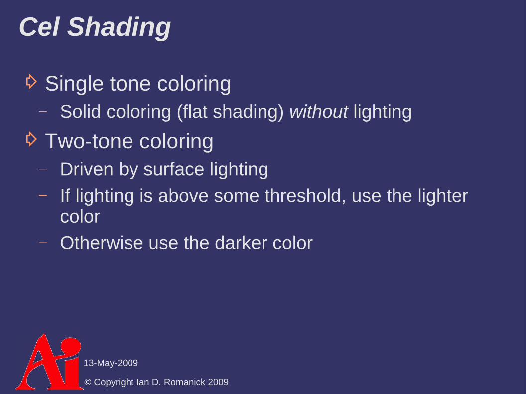
© Copyright Ian D. Romanick 2009
13-May-2009
Cel Shading
⇨ Single tone coloring Solid coloring (flat shading) without lighting
⇨ Two-tone coloring Driven by surface lighting If lighting is above some threshold, use the lighter
color Otherwise use the darker color

© Copyright Ian D. Romanick 2009
13-May-2009
Cel Shading
⇨ Single tone coloring Solid coloring (flat shading) without lighting
⇨ Two-tone coloring Driven by surface lighting If lighting is above some threshold, use the lighter
color Otherwise use the darker color Calculate N⋅L per vertex and interpolate across
surface, check value per fragment Classically done using texture look-ups, but is faster using
conditional assignments on shader hardware

© Copyright Ian D. Romanick 2009
13-May-2009
Cel Boundary Inking
⇨ Anyone who has seen a cartoon or a comic book knows that certain boundaries are “inked”

© Copyright Ian D. Romanick 2009
13-May-2009
Cel Boundary Inking
⇨ Anyone who has seen a cartoon or a comic book knows that certain boundaries are “inked”
⇨ Four main types of edges need inking:

© Copyright Ian D. Romanick 2009
13-May-2009
Cel Boundary Inking
⇨ Anyone who has seen a cartoon or a comic book knows that certain boundaries are “inked”
⇨ Four main types of edges need inking: Border edges – edges not shared by two polygons

© Copyright Ian D. Romanick 2009
13-May-2009
Cel Boundary Inking
⇨ Anyone who has seen a cartoon or a comic book knows that certain boundaries are “inked”
⇨ Four main types of edges need inking: Border edges – edges not shared by two polygons Crease edges – edges where the angle between the
two surfaces is too sharp This angle is called the dihedral angle
Material edge – boundary between two different colors or materials
Silhouette edges – edges where one border polygon faces towards the viewer and the other faces away

© Copyright Ian D. Romanick 2009
13-May-2009
Cel Boundary Inking
⇨ Most boundary types are calculated during authoring or as a pre-processing step
Border edges – edges are added by the artist, by the authoring tool, or are detected in a pre-processing step
Crease edges – dihedral angle is calculated during pre-processing. If N
surface1⋅N
surface2 < cos(60˚), the edge
is a crease Material edge – handled the same as border edges

© Copyright Ian D. Romanick 2009
13-May-2009
Silhouette Edge Rendering
⇨ Silhouette edges are view-dependent and must be calculated at run-time
Conceptually similar to drawing fins in shells-and-fins fur rendering
⇨ Several broad classes of implementations: Surface angle Added geometry Image processing Explicit edge detection

© Copyright Ian D. Romanick 2009
13-May-2009
Silhouette Edge Rendering
⇨ Surface angle test is similar to two-tone cel shading
Examine angle between V and N If angle is near 90˚, use silhouette color
⇨ Pros / cons: Really easy to implement Doesn't work on all models
Generally fails on models with large flat surfaces Only worked on about 25% of the models in the game Cel
Damage1
1 Real-Time Rendering, p. 295

© Copyright Ian D. Romanick 2009
13-May-2009
Silhouette Edge Rendering
⇨ Back-face biasing: Render back-facing geometry by moving it towards
the camera by some small delta
Amount to bias back-face depends on both slope of back-face and slope of front-face
View
Visible silhouette

© Copyright Ian D. Romanick 2009
13-May-2009
Silhouette Edge Rendering
⇨ Edge expansion: Move each face out by some distance along the
plane's normal Not the vertex normal! Adjust the distance according to the desired silhouette
thickness
Create new geometry to fill in the gaps Render back-facing geometry
Moved faces
Added faces
© Copyright Ian D. Romanick 2009
13-May-2009
Silhouette Edge Rendering
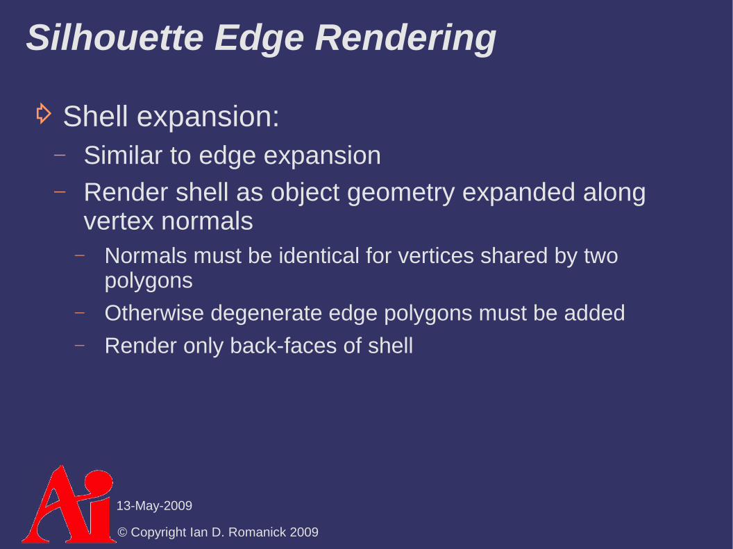
⇨ Shell expansion: Similar to edge expansion Render shell as object geometry expanded along
vertex normals Normals must be identical for vertices shared by two
polygons Otherwise degenerate edge polygons must be added Render only back-faces of shell

© Copyright Ian D. Romanick 2009
13-May-2009
Silhouette Edge Rendering
⇨ Image processing: Render surface normal and depth a texture
Store normal in RGB and most significant portion of depth in alpha
Process texture with separable edge detection filter Card and Mitchell recommend using the Sobel edge
detection filter Store each pass in a texture Composite both textures together over scene

© Copyright Ian D. Romanick 2009
13-May-2009
Silhouette Edge Rendering
⇨ Explicit edge detection: Draw each edge of the object as a line At each vertex, store the normals of the two adjoining
polygons If one normal points towards the viewer and the other
away, draw the line as a silhouette If the two normals point significantly away from each
other, draw the line as a crease

© Copyright Ian D. Romanick 2009
13-May-2009
Gooch-style Technical Illustration
⇨ Many similar ideas to cel shading Use alternate shading Highlight creases Highlight silhouettes
© Copyright Ian D. Romanick 2009
13-May-2009
Gooch-style Technical Illustration
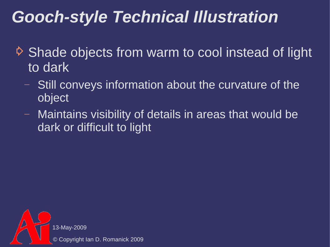
⇨ Shade objects from warm to cool instead of light to dark
Still conveys information about the curvature of the object
Maintains visibility of details in areas that would be dark or difficult to light

© Copyright Ian D. Romanick 2009
13-May-2009
Gooch-style Technical Illustration
⇨ Shade objects from warm to cool instead of light to dark
Still conveys information about the curvature of the object
Maintains visibility of details in areas that would be dark or difficult to light
⇨ Shade in similar manner to cel shading Calculate N⋅L per vertex Use interpolated value per fragment to look up in a 1D
blue-green to yellow-orange gradient texture

© Copyright Ian D. Romanick 2009
13-May-2009
Gooch-style Technical Illustration
⇨ Draw crease edges in white This helps provide information about the model's
orientation

© Copyright Ian D. Romanick 2009
13-May-2009
Gooch-style Technical Illustration
⇨ Draw crease edges in white This helps provide information about the model's
orientation
⇨ Draw silhouette edges in black If an edge is both a crease and a silhouette, it should
be drawn as a silhouette

© Copyright Ian D. Romanick 2009
13-May-2009
Gooch-style Technical Illustration
⇨ Draw crease edges in white This helps provide information about the model's
orientation
⇨ Draw silhouette edges in black If an edge is both a crease and a silhouette, it should
be drawn as a silhouette
⇨ Silhouette and crease edges are handled differently, so the image processing method of inking probably can't be used
Using the explicit edge detection method allows silhouettes and creases to be drawn in a single pass

© Copyright Ian D. Romanick 2009
13-May-2009
References
Gooch, B., Sloan, P. J., Gooch, A., Shirley, P., and Riesenfeld, R. 1999. Interactive technical illustration. In Proceedings of the 1999 Symposium on interactive 3D Graphics (Atlanta, Georgia, United States, April 26 - 29, 1999). I3D '99. ACM, New York, NY, 31-38. http://www.cs.utah.edu/~bgooch/ITI/

© Copyright Ian D. Romanick 2009
13-May-2009
Next week...
⇨ Post-processing effects General image filters Separable filters Depth-of-field

© Copyright Ian D. Romanick 2009
13-May-2009
Legal Statement
This work represents the view of the authors and does not necessarily represent the view of Intel or the Art Institute of Portland.
OpenGL is a trademark of Silicon Graphics, Inc. in the United States, other countries, or both.
Khronos and OpenGL ES are trademarks of the Khronos Group.
Other company, product, and service names may be trademarks or service marks of others.