viavi solutions data sheet viavi · viavi solutions data sheet viavi ... y cable and antenna...
TRANSCRIPT
VIAVI SolutionsData Sheet
VIAVICellAdvisor™JD746B RF Analyzer Specifications
Spectrum Analyzer: 100 kHz to 4 GHz
Cable and Antenna Analyzer: 5 MHz to 4 GHz
Power Meter: 10 MHz to 4 GHz
Specification Conditions
JD746B specifications apply under these conditions:
y The instrument has been turned on for at least 15 minutes
y The instrument is operating within a valid calibration period
y Data with no tolerance are considered typical values
y Cable and antenna measurements apply after calibration to the OSL standard
y Typical and nominal values are defined as:
– Typical: expected performance of the instrument operating at 20 to 30°C after being at this temperature for 15 minutes
– Nominal: a general, descriptive term or parameter
Spectrum Analyzer (standard)FrequencyFrequency accuracy ± (Readout frequency x Internal 10MHz
Frequency reference accuracy + RBW centering + 2 Hz + 0.5 x Horizontal resolution)
Frequency range 100 kHz to 4 GHzInternal 10 MHz Frequency ReferenceAccuracy ±0.05 ppm + aging (0 to 50°C)
±0.01 ppm, after 15 minutes of GPS Lock (0 to 50°C)
Aging ±0.5 ppm/yearFrequency SpanRange 0 Hz (zero span)
10 Hz to 4 GHzResolution 1 HzResolution Bandwidth (RBW)–3 dB bandwidth 1 Hz to 3 MHz 1-3-10 sequenceAccuracy ±10% (nominal)Video Bandwidth (VBW)–3 dB bandwidth 1 Hz to 3 MHz 1-3-10 sequenceAccuracy ±10% (nominal)Single Sideband (SSB) Phase NoiseFc 1 GHz, RBW 10 kHz, VBW 1 kHz, RMS detectorCarrier Offset30 kHz100 kHz1 MHz
<–90 dBc/Hz (typical)<–95 dBc/Hz (typical)<–102 dBc/Hz (typical)
Measurement RangeDANL to +20 dBmInput attenuator range 0 to 50 dB, 5 dB steps
Maximum Input LevelAverage continuous power
+20 dBm
DC voltage ±50 V DC
2 CellAdvisor JD746B RF Analyzer Specifications
Displayed Average Noise Level (DANL)1 Hz RBW, 1 Hz VBW, 50 Ω termination, 0 dB attenuation, RMS detectorPreamplifier Off10 MHz to 2.3 GHz>2.3 GHz to 3 GHz>3 GHz to 4 GHz
–140 dBm (–146 dBm, typical)–138 dBm (–144 dBm, typical)–135 dBm (–140 dBm, typical)
Preamplifier On10 MHz to 2.3 GHz>2.3 GHz to 3 GHz>3 GHz to 4 GHz
–155 dBm (–160 dBm, typical)–153 dBm (–158 dBm, typical)–150 dBm (–156 dBm, typical)
Display RangeLog scale and units (10 divisions displayed)
1 to 20 dB/division in 1 dB stepsdBm, dBV, dBmV, dBµV
Linear scale and units (10 divisions displayed)
V, mV, mW, W
Detectors Normal, positive peak, sample, negative peak, RMS
Number of traces 6Trace functions Clear/write, maximum hold, minimum hold,
capture, load view on/off, trace mathTotal Absolute Amplitude AccuracyPreamplifier off, power level >–50 dBm, auto-coupled (20 to 30°C)5 MHz to 4 GHz ±1.25 dB, ±0.5 dB
(typical)Attenuation <40 dB
±1.55 dB, ±1.0 dB (typical)
Attenuation ≥40 dB
Reference LevelSetting range –120 to +100 dBmSetting ResolutionLog scaleLinear scale
0.1 dB1% of reference level
MarkersMarker types Normal, delta, delta pair, noise,
frequency count markerNumber of markers 6Marker functions Peak, next peak, next peak left, next peak
right, minimum search marker to center/start/stop, always peak on/off
RF Input VSWR20 MHz to 4 GHz 1.5:1 (typical)Second Harmonic DistortionMixer level –25 dBm10 MHz to 1.3 GHz <–65 dBc (typical)>1.3 GHz to 4 GHz <–70 dBc (typical)Third-Order Inter-Modulation (third-order intercept: TOI)200 MHz to 2 GHz +10 dBm (typical)>2 GHz to 4 GHz +12 dBm (typical)
SpuriousInherent residual responseInput terminated, 0 dB attenuation, preamplifier off, RBW at 10 kHz, Sweep mode20 MHz to 3 GHz –90 dBm (nominal)>3 GHz to 4 GHz –85 dBm (nominal)Exceptions < –70 dBm at 85.6MHz/ 227.88/ 770.4/
1791.8/ 2647.8/ 2927.3/ 3195.2/ 3915.1/ 3640 MHz
Input-related spurious <–67 dBc (nominal)Dynamic Range2/3 (TOI-DANL) in 1 Hz RBW
>95 dB
Sweep TimeRange 80 ms to 1000 s
24 µs to 200 s Span = 0 Hz (zero span)
Accuracy ±2% Span = 0 Hz (zero span)Mode Continuous, singleGated SweepTrigger source External, video, and GPSGate length 1 µs to 100 msGate delay 0 to 100 msTriggerTrigger source Free run, video, externalTrigger DelayRange Resolution
0 to 200 s6 µs
Measurements*Channel powerOccupied bandwidthSpectrum emission maskAdjacent channel powerSpurious emissionsField strengthAM/FM audio demodulationRoute mapPIM detectionDual spectrum
* CW signal generator (Option 003) can be set up simultaneously.
3 CellAdvisor JD746B RF Analyzer Specifications
Cable and Antenna Analyzer (standard)Frequency
Range 5 MHz to 4 GHzResolution 10 kHzAccuracy ±25 ppm + aging (20 to 30°C)Aging ±5 ppmData Points
126, 251, 501, 1001Measurement Speed
1.65 ms/point (nominal)Measurement Accuracy
Corrected directivity 40 dBReflection uncertainty ±(0.3 + |20log (1+10-EP/20)|) (typical)
EP = directivity – measured return lossOutput Power
High 0 dBm (typical)Low −30 dBm (typical) Dynamic Range
Reflection 60 dBMaximum Input Level
Average continuous power
+25 dBm (nominal)
DC voltage ±50 V DCInterference ImmunityOn channel On frequency
+17 dBm at >1.4 MHz from carrier frequency (nominal) 0 dBm within ±10 kHz from the carrier frequency (nominal)
Measurements
Reflection (VSWR)VSWR range Return loss range Resolution
1 to 65 0 to 60 dB 0.01
Distance to Fault (DTF)Vertical VSWR range Vertical return loss range Vertical resolution Horizontal range
Horizontal resolution
1 to 65 1 to 60 dB 0.01 0 to (# of data points – 1) x horizontal resolutionMaximum = 1500 m (4921 ft)(1.5 x 10⁸) x (VP)/deltaVP = propagation velocityDelta = stop freq – start freq (Hz)
Cable Loss (1-port)Range Resolution
0 to 30 dB 0.01 dB
1-Port PhaseRange Resolution
–180 to +180° 0.01°
Smith ChartResolution
0.01
RF Power Meter (standard)General ParametersDisplay range 100 to +100 dBm Offset range 0 to 60 dB Resolution 0.01 dB or 0.1 x W (x = m, u, p)Internal RF Power SensorFrequency range 10 MHz to 4 GHz Span 100 kHz to 100 MHzDynamic range –120 to +20 dBmMaximum power +20 dBmAccuracy Same as spectrum analyzerExternal RF Power SensorsDirectional JD731B JD733AFrequency range 300 MHz to 3.8 GHz 150 MHz to 3.5 GHzDynamic range 0.15 to 150 W
(average)4 to 400 W (peak)
0.1 to 50 W (average)0.1 to 50 W (peak)
Connector type Type-N female on both endsMeasurement type Forward/reverse average power,
forward peak power, VSWRAccuracy ±(4% of reading + 0.05 W)1,2
Terminating JD732B JD734B JD736BFrequency range 20 MHz to 3.8 GHzDynamic range –30 to +20 dBmConnector type Type-N maleMeasurement type Average Peak Average and
peakAccuracy ±7%1
Optical Power Meter (standard)Optical Power MeterDisplay range –100 to +100 dBmOffset range 0 to 60 dBResolution 0.01 dB or 0.1 mWExternal Optical Power Sensors
MP-60A MP-80AWavelength range 780 to 1650 nmMax permitted input level
+10 dBm +23 dBm
Connector type Type-N female on both endsConnector input Universal 2.5 and 1.25 mmAccuracy ±5%
1. CW condition at 25°C ±10°C2. Forward power
4 CellAdvisor JD746B RF Analyzer Specifications
2-Port Transmission Measurements (Option 001)Frequency
Frequency range 5 MHz to 4 GHz
Frequency resolution 10 kHz
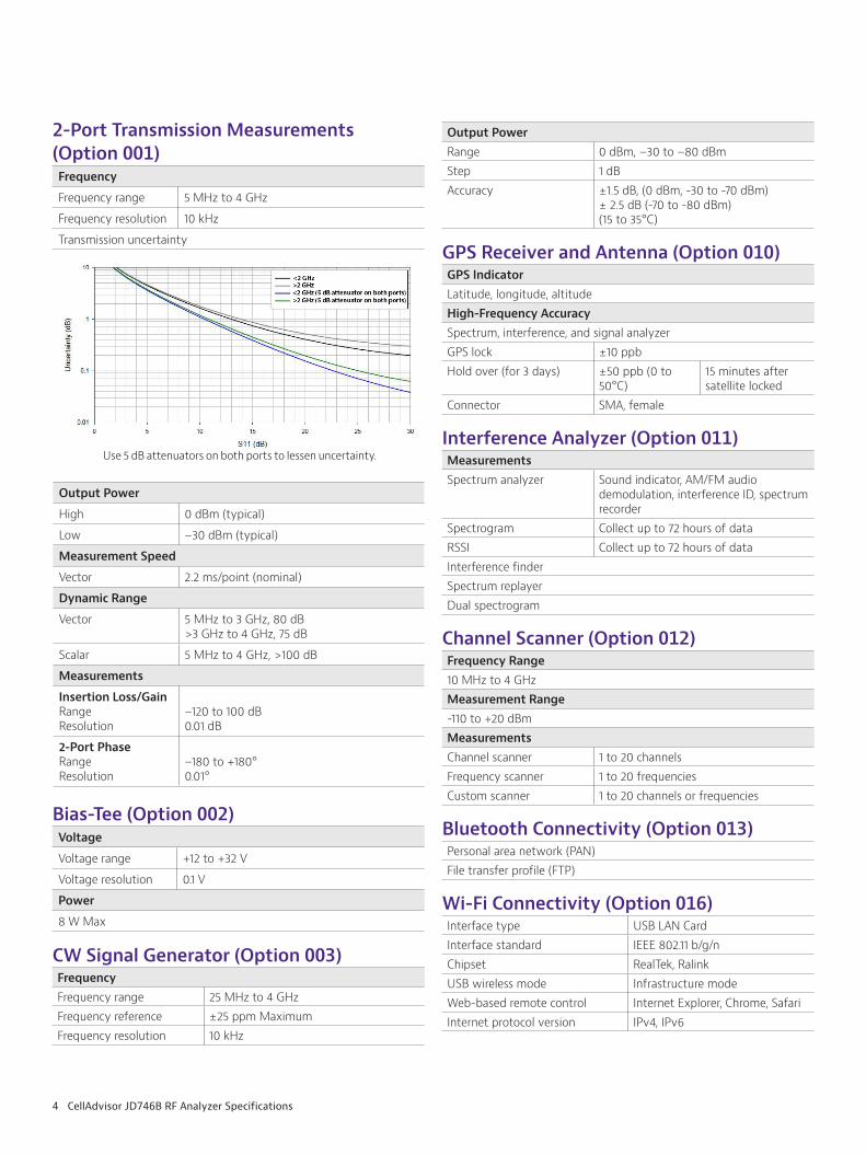
Transmission uncertainty
Use 5 dB attenuators on both ports to lessen uncertainty.
Output Power
High 0 dBm (typical)
Low –30 dBm (typical)
Measurement Speed
Vector 2.2 ms/point (nominal)
Dynamic Range
Vector 5 MHz to 3 GHz, 80 dB>3 GHz to 4 GHz, 75 dB
Scalar 5 MHz to 4 GHz, >100 dB
Measurements
Insertion Loss/Gain Range Resolution
–120 to 100 dB 0.01 dB
2-Port PhaseRange Resolution
–180 to +180° 0.01°
Bias-Tee (Option 002)Voltage
Voltage range +12 to +32 V
Voltage resolution 0.1 V
Power
8 W Max
CW Signal Generator (Option 003)FrequencyFrequency range 25 MHz to 4 GHzFrequency reference ±25 ppm MaximumFrequency resolution 10 kHz
Output PowerRange 0 dBm, –30 to –80 dBm Step 1 dBAccuracy ±1.5 dB, (0 dBm, -30 to -70 dBm)
± 2.5 dB (-70 to -80 dBm)(15 to 35°C)
GPS Receiver and Antenna (Option 010) GPS IndicatorLatitude, longitude, altitudeHigh-Frequency AccuracySpectrum, interference, and signal analyzerGPS lock ±10 ppbHold over (for 3 days) ±50 ppb (0 to
50°C)15 minutes after satellite locked
Connector SMA, female
Interference Analyzer (Option 011)MeasurementsSpectrum analyzer Sound indicator, AM/FM audio
demodulation, interference ID, spectrum recorder
Spectrogram Collect up to 72 hours of dataRSSI Collect up to 72 hours of dataInterference finderSpectrum replayerDual spectrogram
Channel Scanner (Option 012)Frequency Range10 MHz to 4 GHzMeasurement Range-110 to +20 dBmMeasurementsChannel scanner 1 to 20 channelsFrequency scanner 1 to 20 frequenciesCustom scanner 1 to 20 channels or frequencies
Bluetooth Connectivity (Option 013)Personal area network (PAN)File transfer profile (FTP)
Wi-Fi Connectivity (Option 016)Interface type USB LAN CardInterface standard IEEE 802.11 b/g/nChipset RealTek, RalinkUSB wireless mode Infrastructure modeWeb-based remote control Internet Explorer, Chrome, SafariInternet protocol version IPv4, IPv6
5 CellAdvisor JD746B RF Analyzer Specifications
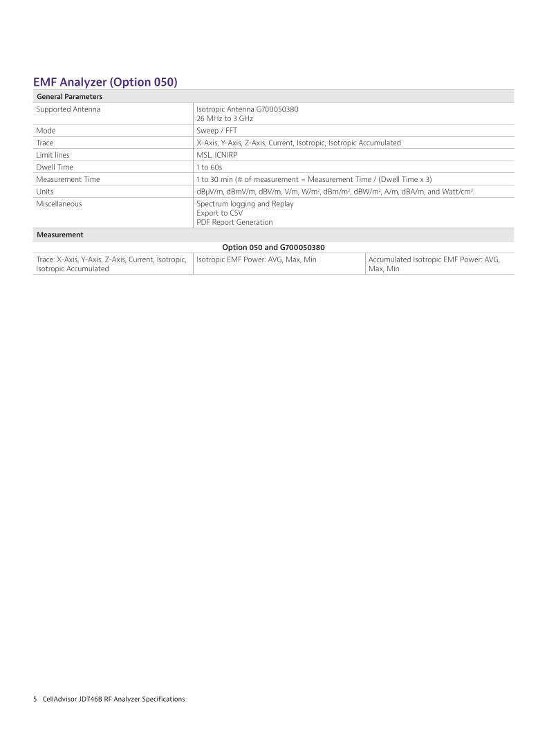
EMF Analyzer (Option 050)General Parameters
Supported Antenna Isotropic Antenna G70005038026 MHz to 3 GHz
Mode Sweep / FFTTrace X-Axis, Y-Axis, Z-Axis, Current, Isotropic, Isotropic AccumulatedLimit lines MSL, ICNIRPDwell Time 1 to 60sMeasurement Time 1 to 30 min (# of measurement = Measurement Time / (Dwell Time x 3)Units dBµV/m, dBmV/m, dBV/m, V/m, W/m2, dBm/m2, dBW/m2, A/m, dBA/m, and Watt/cm2.Miscellaneous Spectrum logging and Replay
Export to CSVPDF Report Generation
Measurement
Option 050 and G700050380Trace: X-Axis, Y-Axis, Z-Axis, Current, Isotropic, Isotropic Accumulated
Isotropic EMF Power: AVG, Max, Min Accumulated Isotropic EMF Power: AVG, Max, Min
6 CellAdvisor JD746B RF Analyzer Specifications
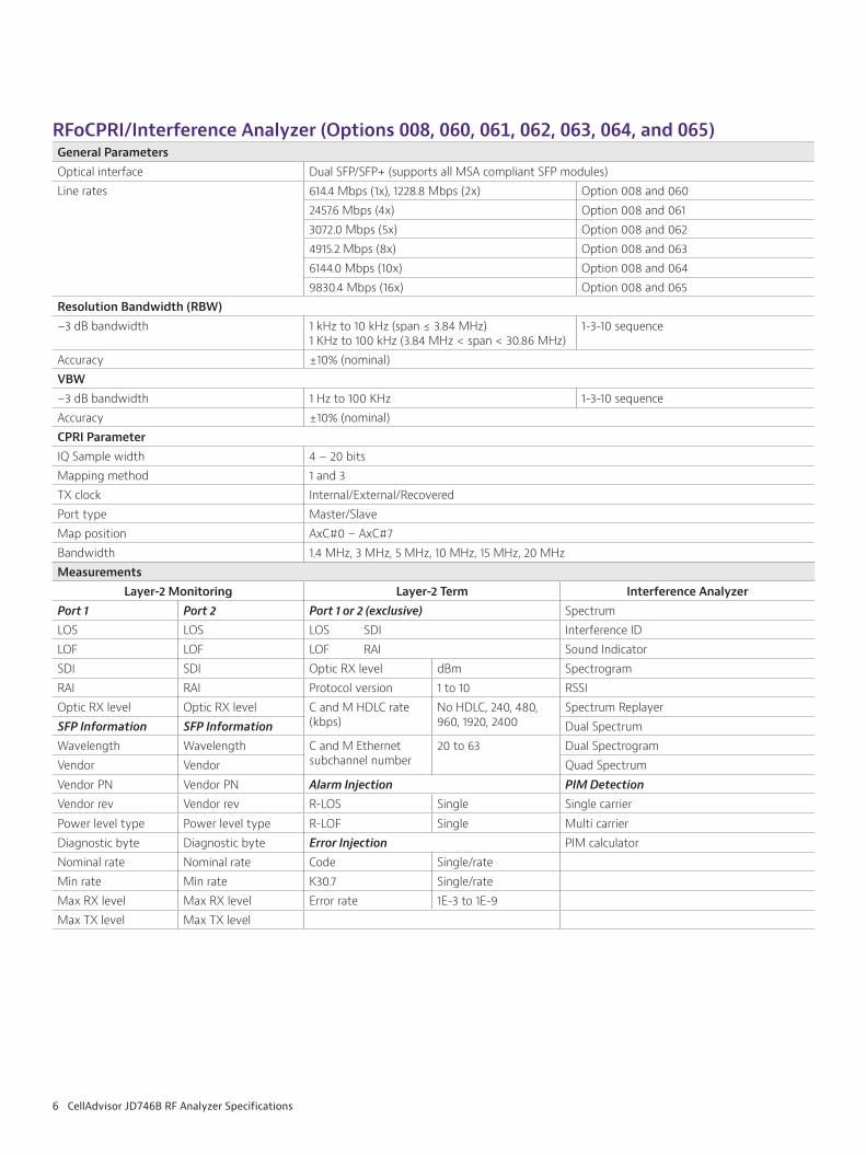
RFoCPRI/Interference Analyzer (Options 008, 060, 061, 062, 063, 064, and 065)General ParametersOptical interface Dual SFP/SFP+ (supports all MSA compliant SFP modules)Line rates 614.4 Mbps (1x), 1228.8 Mbps (2x) Option 008 and 060
2457.6 Mbps (4x) Option 008 and 0613072.0 Mbps (5x) Option 008 and 0624915.2 Mbps (8x) Option 008 and 0636144.0 Mbps (10x) Option 008 and 0649830.4 Mbps (16x) Option 008 and 065
Resolution Bandwidth (RBW)−3 dB bandwidth 1 kHz to 10 kHz (span ≤ 3.84 MHz)
1 KHz to 100 kHz (3.84 MHz < span < 30.86 MHz)1-3-10 sequence
Accuracy ±10% (nominal)VBW−3 dB bandwidth 1 Hz to 100 KHz 1-3-10 sequenceAccuracy ±10% (nominal)CPRI ParameterIQ Sample width 4 − 20 bitsMapping method 1 and 3TX clock Internal/External/RecoveredPort type Master/SlaveMap position AxC#0 – AxC#7Bandwidth 1.4 MHz, 3 MHz, 5 MHz, 10 MHz, 15 MHz, 20 MHzMeasurements
Layer-2 Monitoring Layer-2 Term Interference AnalyzerPort 1 Port 2 Port 1 or 2 (exclusive) SpectrumLOS LOS LOS SDI Interference IDLOF LOF LOF RAI Sound IndicatorSDI SDI Optic RX level dBm SpectrogramRAI RAI Protocol version 1 to 10 RSSIOptic RX level Optic RX level C and M HDLC rate
(kbps)No HDLC, 240, 480, 960, 1920, 2400
Spectrum ReplayerSFP Information SFP Information Dual SpectrumWavelength Wavelength C and M Ethernet
subchannel number20 to 63 Dual Spectrogram
Vendor Vendor Quad SpectrumVendor PN Vendor PN Alarm Injection PIM DetectionVendor rev Vendor rev R-LOS Single Single carrierPower level type Power level type R-LOF Single Multi carrierDiagnostic byte Diagnostic byte Error Injection PIM calculatorNominal rate Nominal rate Code Single/rateMin rate Min rate K30.7 Single/rateMax RX level Max RX level Error rate 1E-3 to 1E-9Max TX level Max TX level
7 CellAdvisor JD746B RF Analyzer Specifications
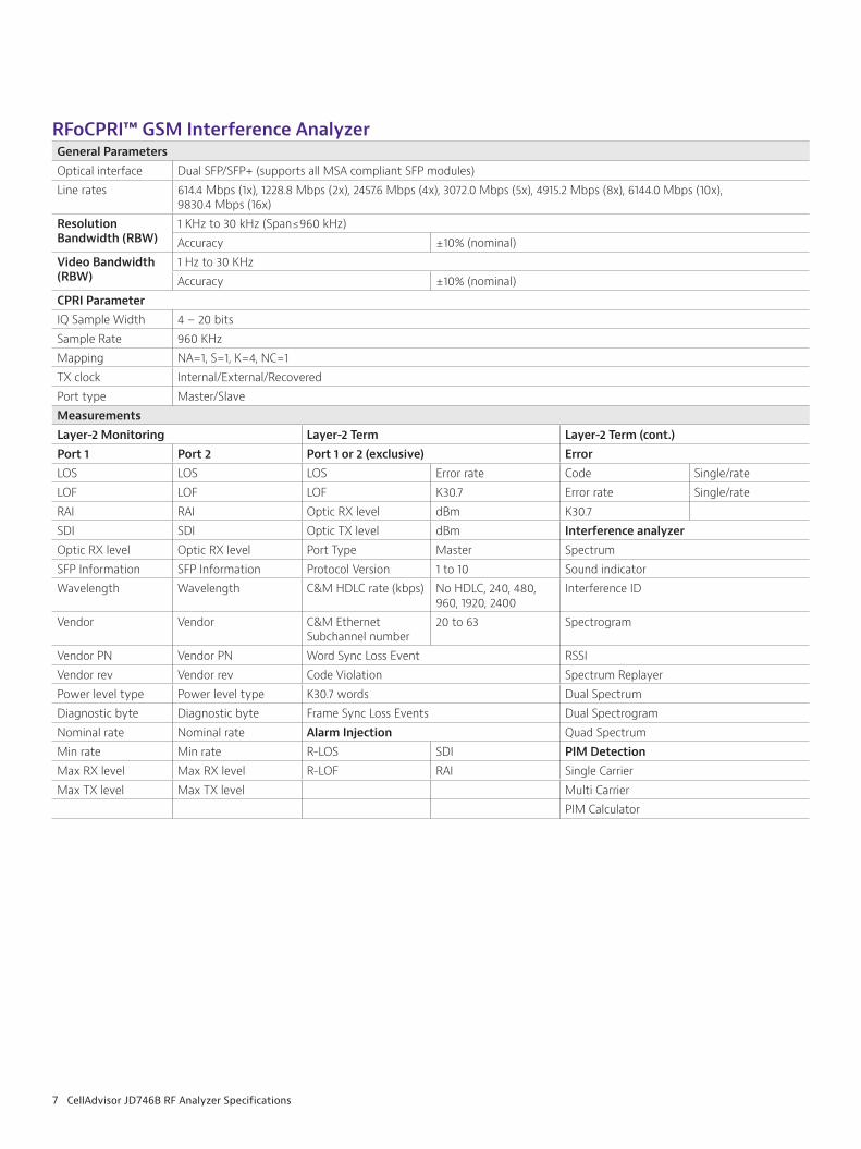
RFoCPRI™ GSM Interference AnalyzerGeneral ParametersOptical interface Dual SFP/SFP+ (supports all MSA compliant SFP modules) Line rates 614.4 Mbps (1x), 1228.8 Mbps (2x), 2457.6 Mbps (4x), 3072.0 Mbps (5x), 4915.2 Mbps (8x), 6144.0 Mbps (10x),
9830.4 Mbps (16x)Resolution Bandwidth (RBW)
1 KHz to 30 kHz (Span≤960 kHz)Accuracy ±10% (nominal)
Video Bandwidth (RBW)
1 Hz to 30 KHzAccuracy ±10% (nominal)
CPRI ParameterIQ Sample Width 4 – 20 bitsSample Rate 960 KHzMapping NA=1, S=1, K=4, NC=1TX clock Internal/External/Recovered Port type Master/Slave MeasurementsLayer-2 Monitoring Layer-2 Term Layer-2 Term (cont.)Port 1 Port 2 Port 1 or 2 (exclusive) ErrorLOS LOS LOS Error rate Code Single/rateLOF LOF LOF K30.7 Error rate Single/rateRAI RAI Optic RX level dBm K30.7SDI SDI Optic TX level dBm Interference analyzer Optic RX level Optic RX level Port Type Master Spectrum SFP Information SFP Information Protocol Version 1 to 10 Sound indicatorWavelength Wavelength C&M HDLC rate (kbps) No HDLC, 240, 480,
960, 1920, 2400Interference ID
Vendor Vendor C&M Ethernet Subchannel number
20 to 63 Spectrogram
Vendor PN Vendor PN Word Sync Loss Event RSSI Vendor rev Vendor rev Code Violation Spectrum Replayer Power level type Power level type K30.7 words Dual SpectrumDiagnostic byte Diagnostic byte Frame Sync Loss Events Dual SpectrogramNominal rate Nominal rate Alarm Injection Quad SpectrumMin rate Min rate R-LOS SDI PIM DetectionMax RX level Max RX level R-LOF RAI Single CarrierMax TX level Max TX level Multi Carrier
PIM Calculator
8 CellAdvisor JD746B RF Analyzer Specifications
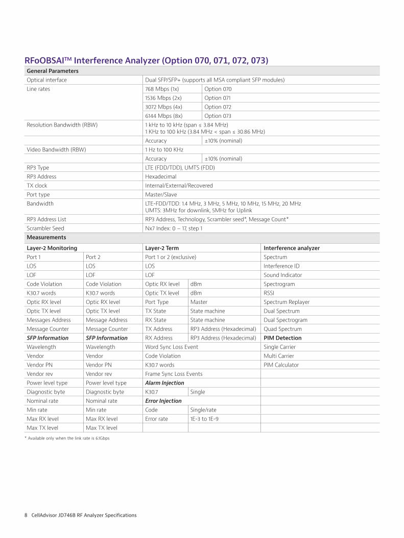
RFoOBSAITM Interference Analyzer (Option 070, 071, 072, 073)General ParametersOptical interface Dual SFP/SFP+ (supports all MSA compliant SFP modules)Line rates 768 Mbps (1x) Option 070
1536 Mbps (2x) Option 071 3072 Mbps (4x) Option 072 6144 Mbps (8x) Option 073
Resolution Bandwidth (RBW) 1 kHz to 10 kHz (span ≤ 3.84 MHz) 1 KHz to 100 kHz (3.84 MHz < span ≤ 30.86 MHz)Accuracy ±10% (nominal)
Video Bandwidth (RBW) 1 Hz to 100 KHzAccuracy ±10% (nominal)
RP3 Type LTE (FDD/TDD), UMTS (FDD)RP3 Address HexadecimalTX clock Internal/External/Recovered Port type Master/Slave Bandwidth LTE-FDD/TDD: 1.4 MHz, 3 MHz, 5 MHz, 10 MHz, 15 MHz, 20 MHz
UMTS: 3MHz for downlink, 5MHz for UplinkRP3 Address List RP3 Address, Technology, Scrambler seed*, Message Count*Scrambler Seed Nx7 Index: 0 – 17, step 1Measurements
Layer-2 MonitoringPort 1 Port 2 LOS LOS LOF LOF Code Violation Code ViolationK30.7 words K30.7 wordsOptic RX level Optic RX level Optic TX level Optic TX level Messages Address Message AddressMessage Counter Message CounterSFP Information SFP Information Wavelength Wavelength Vendor Vendor Vendor PN Vendor PN Vendor rev Vendor rev Power level type Power level type Diagnostic byte Diagnostic byte Nominal rate Nominal rate Min rate Min rate Max RX level Max RX level Max TX level Max TX level
Layer-2 TermPort 1 or 2 (exclusive)LOSLOFOptic RX level dBmOptic TX level dBmPort Type MasterTX State State machineRX State State machineTX Address RP3 Address (Hexadecimal)RX Address RP3 Address (Hexadecimal)Word Sync Loss EventCode ViolationK30.7 wordsFrame Sync Loss EventsAlarm InjectionK30.7 SingleError InjectionCode Single/rateError rate 1E-3 to 1E-9
Interference analyzer SpectrumInterference IDSound IndicatorSpectrogramRSSISpectrum ReplayerDual SpectrumDual SpectrogramQuad SpectrumPIM DetectionSingle CarrierMulti CarrierPIM Calculator
* Available only when the link rate is 6.1Gbps
9 CellAdvisor JD746B RF Analyzer Specifications
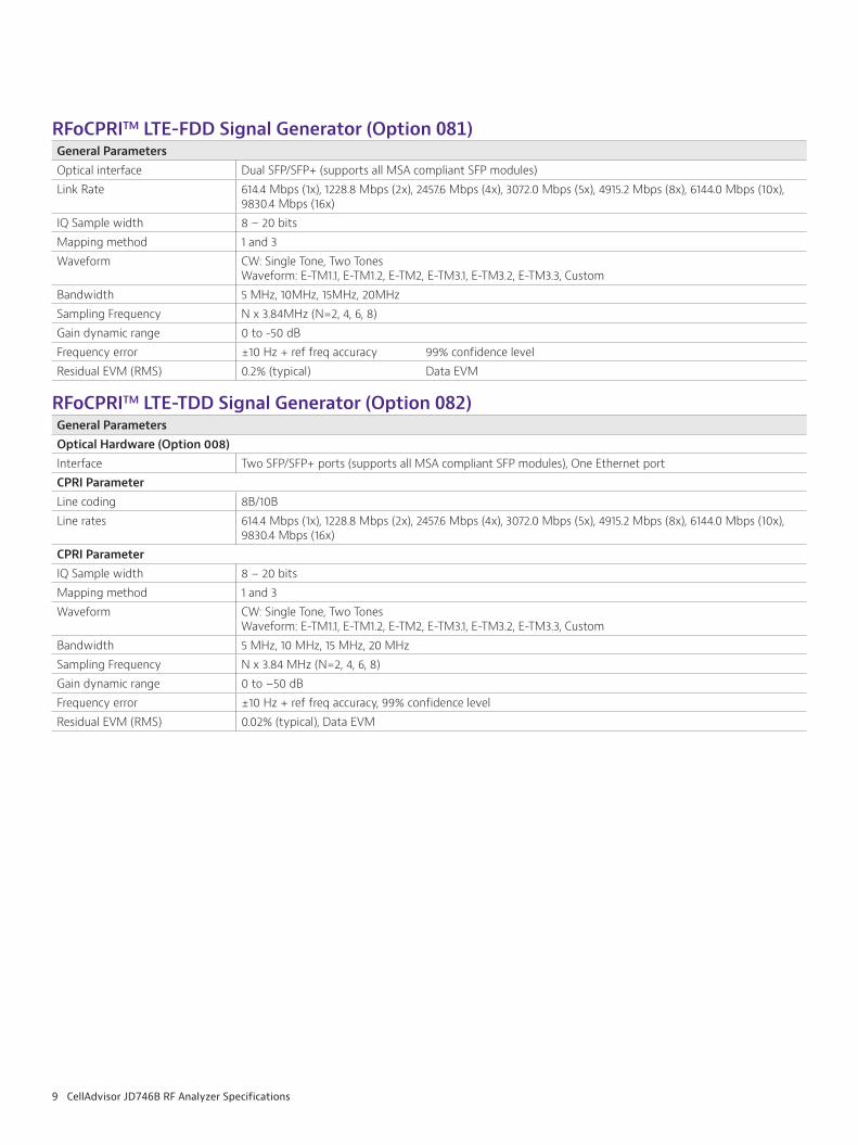
RFoCPRITM LTE-FDD Signal Generator (Option 081)General ParametersOptical interface Dual SFP/SFP+ (supports all MSA compliant SFP modules) Link Rate 614.4 Mbps (1x), 1228.8 Mbps (2x), 2457.6 Mbps (4x), 3072.0 Mbps (5x), 4915.2 Mbps (8x), 6144.0 Mbps (10x),
9830.4 Mbps (16x)IQ Sample width 8 – 20 bitsMapping method 1 and 3Waveform CW: Single Tone, Two Tones
Waveform: E-TM1.1, E-TM1.2, E-TM2, E-TM3.1, E-TM3.2, E-TM3.3, CustomBandwidth 5 MHz, 10MHz, 15MHz, 20MHz Sampling Frequency N x 3.84MHz (N=2, 4, 6, 8)Gain dynamic range 0 to -50 dBFrequency error ±10 Hz + ref freq accuracy 99% confidence level Residual EVM (RMS) 0.2% (typical) Data EVM
RFoCPRITM LTE-TDD Signal Generator (Option 082)General ParametersOptical Hardware (Option 008)Interface Two SFP/SFP+ ports (supports all MSA compliant SFP modules), One Ethernet portCPRI ParameterLine coding 8B/10BLine rates 614.4 Mbps (1x), 1228.8 Mbps (2x), 2457.6 Mbps (4x), 3072.0 Mbps (5x), 4915.2 Mbps (8x), 6144.0 Mbps (10x),
9830.4 Mbps (16x)CPRI ParameterIQ Sample width 8 − 20 bitsMapping method 1 and 3Waveform CW: Single Tone, Two Tones
Waveform: E-TM1.1, E-TM1.2, E-TM2, E-TM3.1, E-TM3.2, E-TM3.3, CustomBandwidth 5 MHz, 10 MHz, 15 MHz, 20 MHzSampling Frequency N x 3.84 MHz (N=2, 4, 6, 8)Gain dynamic range 0 to −50 dBFrequency error ±10 Hz + ref freq accuracy, 99% confidence level Residual EVM (RMS) 0.02% (typical), Data EVM
10 CellAdvisor JD746B RF Analyzer Specifications
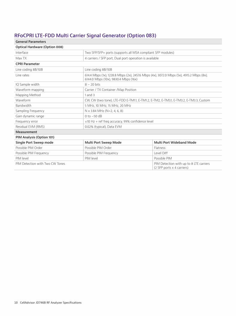
RFoCPRI LTE-FDD Multi Carrier Signal Generator (Option 083)General ParametersOptical Hardware (Option 008)
Interface Two SFP/SFP+ ports (supports all MSA compliant SFP modules)
Max TX 4 carriers / SFP port, Dual port operation is available
CPRI Parameter
Line coding 8B/10B Line coding 8B/10B
Line rates 614.4 Mbps (1x), 1228.8 Mbps (2x), 2457.6 Mbps (4x), 3072.0 Mbps (5x), 4915.2 Mbps (8x),6144.0 Mbps (10x), 9830.4 Mbps (16x)
IQ Sample width 8 − 20 bitsWaveform mapping Carrier / TX Container /Map PositionMapping Method 1 and 3Waveform CW, CW (two tone), LTE-FDD E-TM1.1, E-TM1.2, E-TM2, E-TM3.1, E-TM3.2, E-TM3.3, CustomBandwidth 5 MHz, 10 MHz, 15 MHz, 20 MHzSampling Frequency N x 3.84 MHz (N=2, 4, 6, 8)Gain dynamic range 0 to −50 dBFrequency error ±10 Hz + ref freq accuracy, 99% confidence levelResidual EVM (RMS) 0.02% (typical), Data EVMMeasurement PIM Analysis (Option 101)Single Port Sweep mode Multi Port Sweep Mode Multi Port Wideband ModePossible PIM Order Possible PIM Order FlatnessPossible PIM Frequency Possible PIM Frequency Level DiffPIM level PIM level Possible PIMPIM Detection with Two CW Tones PIM Detection with up to 8 LTE carriers
(2 SFP ports x 4 carriers)
11 CellAdvisor JD746B RF Analyzer Specifications
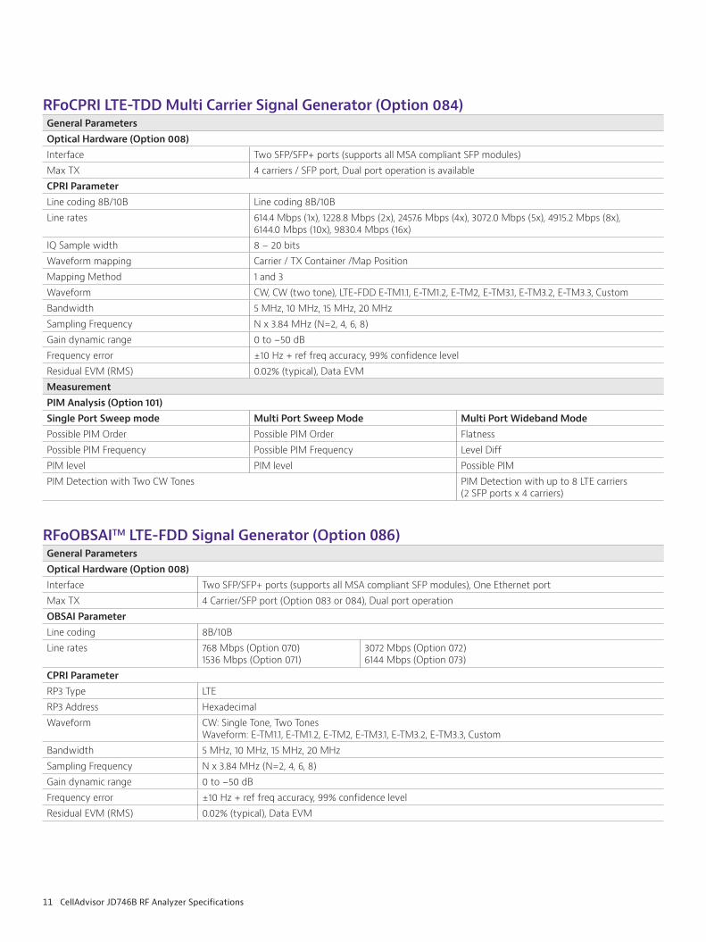
RFoOBSAITM LTE-FDD Signal Generator (Option 086)General ParametersOptical Hardware (Option 008)Interface Two SFP/SFP+ ports (supports all MSA compliant SFP modules), One Ethernet portMax TX 4 Carrier/SFP port (Option 083 or 084), Dual port operationOBSAI ParameterLine coding 8B/10BLine rates 768 Mbps (Option 070)
1536 Mbps (Option 071)3072 Mbps (Option 072)6144 Mbps (Option 073)
CPRI ParameterRP3 Type LTERP3 Address HexadecimalWaveform CW: Single Tone, Two Tones
Waveform: E-TM1.1, E-TM1.2, E-TM2, E-TM3.1, E-TM3.2, E-TM3.3, CustomBandwidth 5 MHz, 10 MHz, 15 MHz, 20 MHzSampling Frequency N x 3.84 MHz (N=2, 4, 6, 8)Gain dynamic range 0 to −50 dBFrequency error ±10 Hz + ref freq accuracy, 99% confidence level Residual EVM (RMS) 0.02% (typical), Data EVM
RFoCPRI LTE-TDD Multi Carrier Signal Generator (Option 084)General ParametersOptical Hardware (Option 008)Interface Two SFP/SFP+ ports (supports all MSA compliant SFP modules)Max TX 4 carriers / SFP port, Dual port operation is availableCPRI ParameterLine coding 8B/10B Line coding 8B/10BLine rates 614.4 Mbps (1x), 1228.8 Mbps (2x), 2457.6 Mbps (4x), 3072.0 Mbps (5x), 4915.2 Mbps (8x),
6144.0 Mbps (10x), 9830.4 Mbps (16x)IQ Sample width 8 − 20 bitsWaveform mapping Carrier / TX Container /Map PositionMapping Method 1 and 3Waveform CW, CW (two tone), LTE-FDD E-TM1.1, E-TM1.2, E-TM2, E-TM3.1, E-TM3.2, E-TM3.3, CustomBandwidth 5 MHz, 10 MHz, 15 MHz, 20 MHzSampling Frequency N x 3.84 MHz (N=2, 4, 6, 8)Gain dynamic range 0 to −50 dBFrequency error ±10 Hz + ref freq accuracy, 99% confidence levelResidual EVM (RMS) 0.02% (typical), Data EVMMeasurement PIM Analysis (Option 101)Single Port Sweep mode Multi Port Sweep Mode Multi Port Wideband ModePossible PIM Order Possible PIM Order FlatnessPossible PIM Frequency Possible PIM Frequency Level DiffPIM level PIM level Possible PIMPIM Detection with Two CW Tones PIM Detection with up to 8 LTE carriers
(2 SFP ports x 4 carriers)
12 CellAdvisor JD746B RF Analyzer Specifications
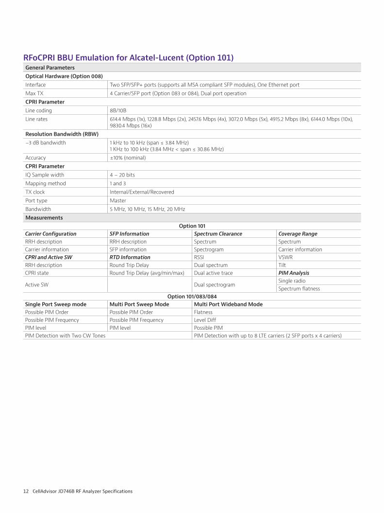
RFoCPRI BBU Emulation for Alcatel-Lucent (Option 101)General ParametersOptical Hardware (Option 008)Interface Two SFP/SFP+ ports (supports all MSA compliant SFP modules), One Ethernet portMax TX 4 Carrier/SFP port (Option 083 or 084), Dual port operationCPRI ParameterLine coding 8B/10BLine rates 614.4 Mbps (1x), 1228.8 Mbps (2x), 2457.6 Mbps (4x), 3072.0 Mbps (5x), 4915.2 Mbps (8x), 6144.0 Mbps (10x),
9830.4 Mbps (16x)Resolution Bandwidth (RBW)−3 dB bandwidth 1 kHz to 10 kHz (span ≤ 3.84 MHz)
1 KHz to 100 kHz (3.84 MHz < span ≤ 30.86 MHz)Accuracy ±10% (nominal)CPRI ParameterIQ Sample width 4 − 20 bitsMapping method 1 and 3TX clock Internal/External/RecoveredPort type MasterBandwidth 5 MHz, 10 MHz, 15 MHz, 20 MHzMeasurements
Option 101Carrier Configuration SFP Information Spectrum Clearance Coverage RangeRRH description RRH description Spectrum SpectrumCarrier information SFP information Spectrogram Carrier informationCPRI and Active SW RTD Information RSSI VSWRRRH description Round Trip Delay Dual spectrum TiltCPRI state Round Trip Delay (avg/min/max) Dual active trace PIM Analysis
Active SW Dual spectrogramSingle radioSpectrum flatness
Option 101/083/084Single Port Sweep mode Multi Port Sweep Mode Multi Port Wideband ModePossible PIM Order Possible PIM Order FlatnessPossible PIM Frequency Possible PIM Frequency Level DiffPIM level PIM level Possible PIMPIM Detection with Two CW Tones PIM Detection with up to 8 LTE carriers (2 SFP ports x 4 carriers)
13 CellAdvisor JD746B RF Analyzer Specifications
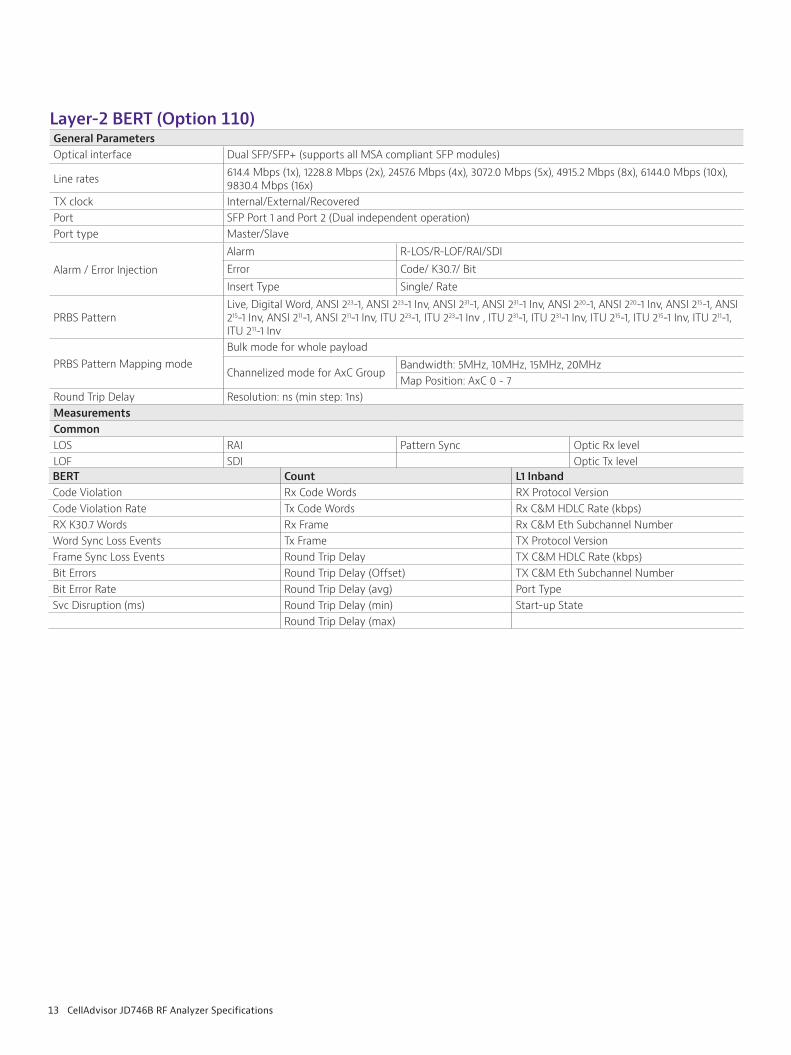
Layer-2 BERT (Option 110)General ParametersOptical interface Dual SFP/SFP+ (supports all MSA compliant SFP modules)
Line rates 614.4 Mbps (1x), 1228.8 Mbps (2x), 2457.6 Mbps (4x), 3072.0 Mbps (5x), 4915.2 Mbps (8x), 6144.0 Mbps (10x), 9830.4 Mbps (16x)
TX clock Internal/External/Recovered Port SFP Port 1 and Port 2 (Dual independent operation)Port type Master/Slave
Alarm / Error Injection
Alarm R-LOS/R-LOF/RAI/SDIError Code/ K30.7/ BitInsert Type Single/ Rate
PRBS PatternLive, Digital Word, ANSI 223-1, ANSI 223-1 Inv, ANSI 231-1, ANSI 231-1 Inv, ANSI 220-1, ANSI 220-1 Inv, ANSI 215-1, ANSI 215-1 Inv, ANSI 211-1, ANSI 211-1 Inv, ITU 223-1, ITU 223-1 Inv , ITU 231-1, ITU 231-1 Inv, ITU 215-1, ITU 215-1 Inv, ITU 211-1, ITU 211-1 Inv
PRBS Pattern Mapping modeBulk mode for whole payload
Channelized mode for AxC GroupBandwidth: 5MHz, 10MHz, 15MHz, 20MHzMap Position: AxC 0 - 7
Round Trip Delay Resolution: ns (min step: 1ns)MeasurementsCommonLOS RAI Pattern Sync Optic Rx levelLOF SDI Optic Tx levelBERT Count L1 InbandCode Violation Rx Code Words RX Protocol VersionCode Violation Rate Tx Code Words Rx C&M HDLC Rate (kbps)RX K30.7 Words Rx Frame Rx C&M Eth Subchannel NumberWord Sync Loss Events Tx Frame TX Protocol VersionFrame Sync Loss Events Round Trip Delay TX C&M HDLC Rate (kbps)Bit Errors Round Trip Delay (Offset) TX C&M Eth Subchannel NumberBit Error Rate Round Trip Delay (avg) Port TypeSvc Disruption (ms) Round Trip Delay (min) Start-up State
Round Trip Delay (max)
14 CellAdvisor JD746B RF Analyzer Specifications
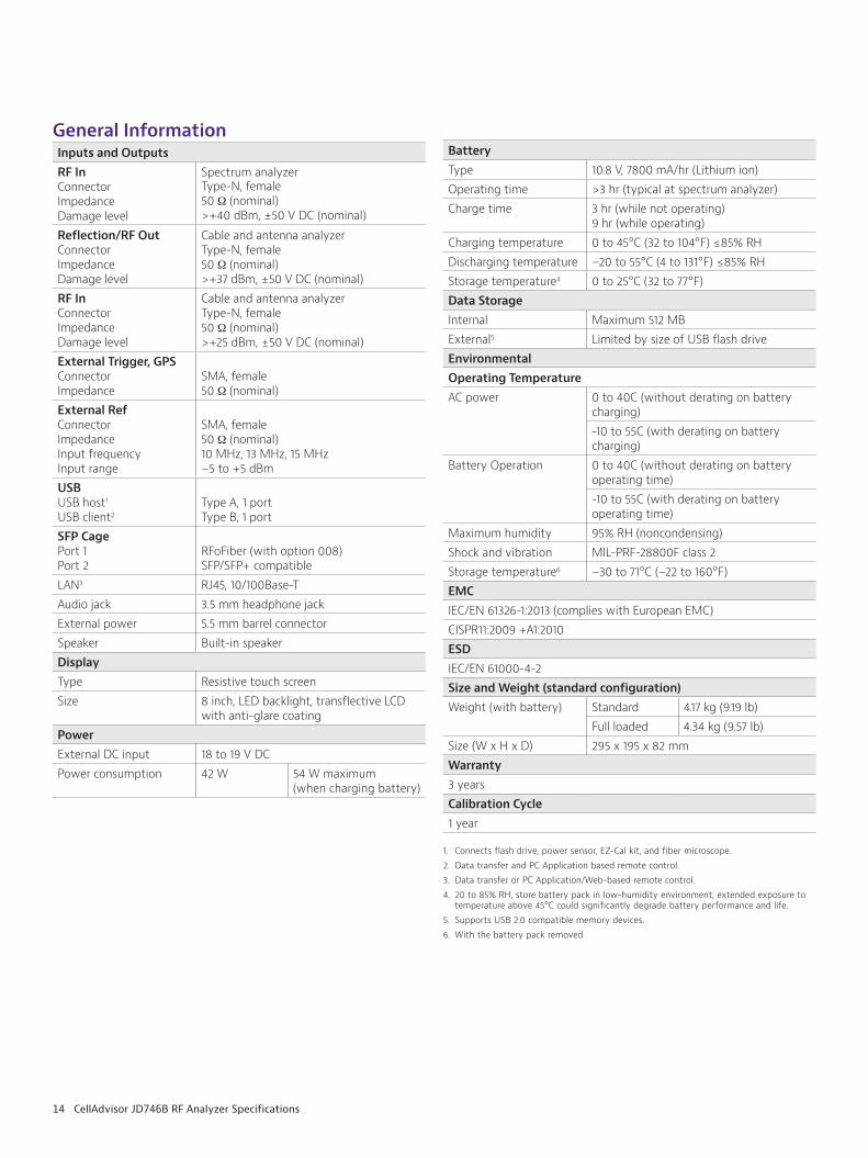
General InformationInputs and OutputsRF InConnectorImpedanceDamage level
Spectrum analyzer Type-N, female 50 Ω (nominal) >+40 dBm, ±50 V DC (nominal)
Reflection/RF OutConnectorImpedanceDamage level
Cable and antenna analyzer Type-N, female50 Ω (nominal)>+37 dBm, ±50 V DC (nominal)
RF InConnectorImpedanceDamage level
Cable and antenna analyzer Type-N, female 50 Ω (nominal) >+25 dBm, ±50 V DC (nominal)
External Trigger, GPSConnectorImpedance
SMA, female50 Ω (nominal)
External RefConnector ImpedanceInput frequencyInput range
SMA, female50 Ω (nominal)10 MHz, 13 MHz, 15 MHz–5 to +5 dBm
USBUSB host1
USB client2
Type A, 1 port Type B, 1 port
SFP CagePort 1Port 2
RFoFiber (with option 008)SFP/SFP+ compatible
LAN3 RJ45, 10/100Base-TAudio jack 3.5 mm headphone jackExternal power 5.5 mm barrel connectorSpeaker Built-in speakerDisplayType Resistive touch screen Size 8 inch, LED backlight, transflective LCD
with anti-glare coatingPowerExternal DC input 18 to 19 V DCPower consumption 42 W 54 W maximum
(when charging battery)
BatteryType 10.8 V, 7800 mA/hr (Lithium ion)Operating time >3 hr (typical at spectrum analyzer)Charge time 3 hr (while not operating)
9 hr (while operating)Charging temperature 0 to 45°C (32 to 104°F) ≤85% RHDischarging temperature –20 to 55°C (4 to 131°F) ≤85% RHStorage temperature4 0 to 25°C (32 to 77°F)Data StorageInternal Maximum 512 MBExternal5 Limited by size of USB flash driveEnvironmentalOperating TemperatureAC power 0 to 40C (without derating on battery
charging)-10 to 55C (with derating on battery charging)
Battery Operation 0 to 40C (without derating on battery operating time)-10 to 55C (with derating on battery operating time)
Maximum humidity 95% RH (noncondensing)Shock and vibration MIL-PRF-28800F class 2Storage temperature6 –30 to 71°C (–22 to 160°F)EMCIEC/EN 61326-1:2013 (complies with European EMC)CISPR11:2009 +A1:2010ESDIEC/EN 61000-4-2Size and Weight (standard configuration)Weight (with battery) Standard 4.17 kg (9.19 lb)
Full loaded 4.34 kg (9.57 lb)Size (W x H x D) 295 x 195 x 82 mmWarranty3 yearsCalibration Cycle1 year
1. Connects flash drive, power sensor, EZ-Cal kit, and fiber microscope. 2. Data transfer and PC Application based remote control.3. Data transfer or PC Application/Web-based remote control.4. 20 to 85% RH, store battery pack in low-humidity environment; extended exposure to
temperature above 45°C could significantly degrade battery performance and life. 5. Supports USB 2.0 compatible memory devices. 6. With the battery pack removed
15 CellAdvisor JD746B RF Analyzer Specifications
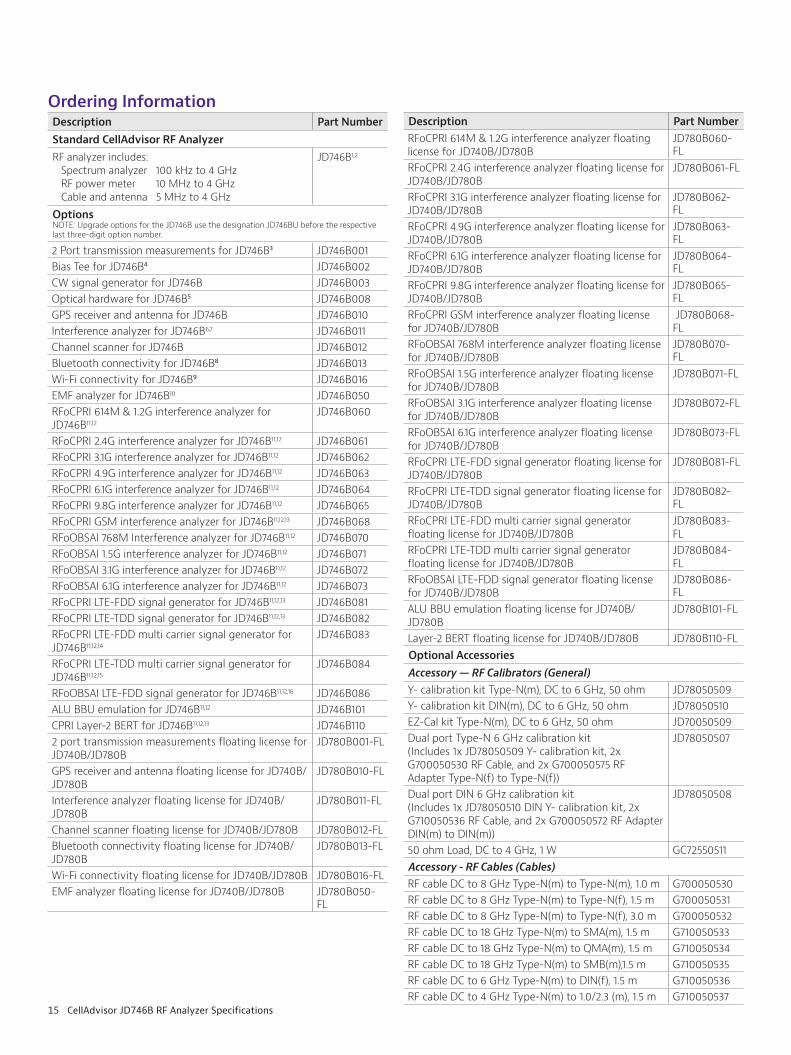
Ordering InformationDescription Part NumberStandard CellAdvisor RF AnalyzerRF analyzer includes: Spectrum analyzer 100 kHz to 4 GHz RF power meter 10 MHz to 4 GHz Cable and antenna 5 MHz to 4 GHz
JD746B1,2
OptionsNOTE: Upgrade options for the JD746B use the designation JD746BU before the respective last three-digit option number.
2 Port transmission measurements for JD746B³ JD746B001Bias Tee for JD746B⁴ JD746B002CW signal generator for JD746B JD746B003Optical hardware for JD746B⁵ JD746B008GPS receiver and antenna for JD746B JD746B010Interference analyzer for JD746B6,7 JD746B011Channel scanner for JD746B JD746B012Bluetooth connectivity for JD746B⁸ JD746B013Wi-Fi connectivity for JD746B⁹ JD746B016EMF analyzer for JD746B10 JD746B050RFoCPRI 614M & 1.2G interference analyzer for JD746B11,12
JD746B060
RFoCPRI 2.4G interference analyzer for JD746B11,12 JD746B061RFoCPRI 3.1G interference analyzer for JD746B11,12 JD746B062RFoCPRI 4.9G interference analyzer for JD746B11,12 JD746B063RFoCPRI 6.1G interference analyzer for JD746B11,12 JD746B064RFoCPRI 9.8G interference analyzer for JD746B11,12 JD746B065RFoCPRI GSM interference analyzer for JD746B11,12,13 JD746B068RFoOBSAI 768M Interference analyzer for JD746B11,12 JD746B070RFoOBSAI 1.5G interference analyzer for JD746B11,12 JD746B071RFoOBSAI 3.1G interference analyzer for JD746B11,12 JD746B072RFoOBSAI 6.1G interference analyzer for JD746B11,12 JD746B073RFoCPRI LTE-FDD signal generator for JD746B11,12,13 JD746B081RFoCPRI LTE-TDD signal generator for JD746B11,12,13 JD746B082RFoCPRI LTE-FDD multi carrier signal generator for JD746B11,12,14
JD746B083
RFoCPRI LTE-TDD multi carrier signal generator for JD746B11,12,15
JD746B084
RFoOBSAI LTE-FDD signal generator for JD746B11,12,16 JD746B086ALU BBU emulation for JD746B11,12 JD746B101CPRI Layer-2 BERT for JD746B11,12,13 JD746B1102 port transmission measurements floating license for JD740B/JD780B
JD780B001-FL
GPS receiver and antenna floating license for JD740B/JD780B
JD780B010-FL
Interference analyzer floating license for JD740B/JD780B
JD780B011-FL
Channel scanner floating license for JD740B/JD780B JD780B012-FLBluetooth connectivity floating license for JD740B/JD780B
JD780B013-FL
Wi-Fi connectivity floating license for JD740B/JD780B JD780B016-FLEMF analyzer floating license for JD740B/JD780B JD780B050-
FL
Description Part NumberRFoCPRI 614M & 1.2G interference analyzer floating license for JD740B/JD780B
JD780B060-FL
RFoCPRI 2.4G interference analyzer floating license for JD740B/JD780B
JD780B061-FL
RFoCPRI 3.1G interference analyzer floating license for JD740B/JD780B
JD780B062-FL
RFoCPRI 4.9G interference analyzer floating license for JD740B/JD780B
JD780B063-FL
RFoCPRI 6.1G interference analyzer floating license for JD740B/JD780B
JD780B064-FL
RFoCPRI 9.8G interference analyzer floating license for JD740B/JD780B
JD780B065-FL
RFoCPRI GSM interference analyzer floating license for JD740B/JD780B
JD780B068-FL
RFoOBSAI 768M interference analyzer floating license for JD740B/JD780B
JD780B070-FL
RFoOBSAI 1.5G interference analyzer floating license for JD740B/JD780B
JD780B071-FL
RFoOBSAI 3.1G interference analyzer floating license for JD740B/JD780B
JD780B072-FL
RFoOBSAI 6.1G interference analyzer floating license for JD740B/JD780B
JD780B073-FL
RFoCPRI LTE-FDD signal generator floating license for JD740B/JD780B
JD780B081-FL
RFoCPRI LTE-TDD signal generator floating license for JD740B/JD780B
JD780B082-FL
RFoCPRI LTE-FDD multi carrier signal generator floating license for JD740B/JD780B
JD780B083-FL
RFoCPRI LTE-TDD multi carrier signal generator floating license for JD740B/JD780B
JD780B084-FL
RFoOBSAI LTE-FDD signal generator floating license for JD740B/JD780B
JD780B086-FL
ALU BBU emulation floating license for JD740B/JD780B
JD780B101-FL
Layer-2 BERT floating license for JD740B/JD780B JD780B110-FLOptional AccessoriesAccessory — RF Calibrators (General)Y- calibration kit Type-N(m), DC to 6 GHz, 50 ohm JD78050509Y- calibration kit DIN(m), DC to 6 GHz, 50 ohm JD78050510EZ-Cal kit Type-N(m), DC to 6 GHz, 50 ohm JD70050509Dual port Type-N 6 GHz calibration kit(Includes 1x JD78050509 Y- calibration kit, 2x G700050530 RF Cable, and 2x G700050575 RF Adapter Type-N(f) to Type-N(f))
JD78050507
Dual port DIN 6 GHz calibration kit(Includes 1x JD78050510 DIN Y- calibration kit, 2x G710050536 RF Cable, and 2x G700050572 RF Adapter DIN(m) to DIN(m))
JD78050508
50 ohm Load, DC to 4 GHz, 1 W GC72550511Accessory - RF Cables (Cables)RF cable DC to 8 GHz Type-N(m) to Type-N(m), 1.0 m G700050530RF cable DC to 8 GHz Type-N(m) to Type-N(f), 1.5 m G700050531RF cable DC to 8 GHz Type-N(m) to Type-N(f), 3.0 m G700050532RF cable DC to 18 GHz Type-N(m) to SMA(m), 1.5 m G710050533RF cable DC to 18 GHz Type-N(m) to QMA(m), 1.5 m G710050534RF cable DC to 18 GHz Type-N(m) to SMB(m),1.5 m G710050535RF cable DC to 6 GHz Type-N(m) to DIN(f), 1.5 m G710050536RF cable DC to 4 GHz Type-N(m) to 1.0/2.3 (m), 1.5 m G710050537
16 CellAdvisor JD746B RF Analyzer Specifications
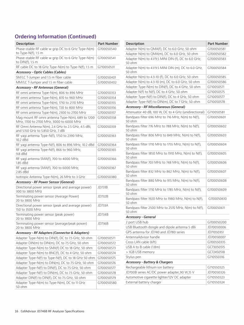
Description Part NumberPhase-stable RF cable w grip DC to 6 GHz Type-N(m) to Type-N(f), 1.5 m
G700050540
Phase-stable RF cable w grip DC to 6 GHz Type-N(m) to DIN(f), 1.5 m
G700050541
RF cable DC to 18 GHz Type-N(m) to Type-N(f), 1.5 m G710050531Accessory - Optic Cables (Cables)SM/LC T-Jumper and 1.5 m fiber cable G700050401MM/LC T-Jumper and 1.5 m fiber cable G700050402Accessory - RF Antennas (General) RF omni antenna Type-N(m), 806 to 896 MHz G700050353RF omni antenna Type-N(m), 870 to 960 MHz G700050354RF omni antenna Type-N(m), 1710 to 2170 MHz G700050355RF omni antenna Type-N(m), 720 to 800 MHz G700050356RF omni antenna Type-N(m), 2300 to 2700 MHz G700050357Mag mount RF omni antenna Type-N(m), 689 to 1200 MHz, 1700 to 2700 MHz, 3000 to 6000 MHz
G700050358
RF Omni Antenna N(m), 2.4 GHz to 2.5 GHz, 4.5 dBi, and 5.150 GHz to 5.850 GHz, 7 dBi
G700050359
RF yagi antenna Type-N(f), 1750 to 2390 MHz, 10.2 dBd
G700050363
RF yagi antenna Type-N(f), 806 to 896 MHz, 10.2 dBd G700050364RF yagi antenna Type-N(f), 866 to 960 MHz, 9.8 dBd
G700050365
RF yagi antenna SMA(f), 700 to 4000 MHz, 1.85 dBd
G700050366
RF yagi antenna SMA(f), 700 to 6000 MHz, 2.85 dBd
G700050367
Isotropic Antenna Type-N(m), 26 MHz to 3 GHz G700050380Accessory - RF Power Sensor (General)Directional power sensor (peak and average power) 300 to 3800 MHz
JD731B
Terminating power sensor (Average Power) 20 to 3800 MHz
JD732B
Directional power sensor (peak and average power) 150 to 3500 MHz
JD733A
Terminating power sensor (peak power) 20 to 3800 MHz
JD734B
Terminating power sensor (average/peak power) 20 to 3800 MHz
JD736B
Accessory - RF Adapters (Connector & Adapters)Adapter Type-N(m) to DIN(f), DC to 7.5 GHz, 50 ohm G700050571Adapter DIN(m) to DIN(m), DC to 7.5 GHz, 50 ohm G700050572Adapter Type-N(m) to SMA(f) DC to 18 GHz, 50 ohm G700050573Adapter Type-N(m) to BNC(f), DC to 4 GHz, 50 ohm G700050574Adapter Type-N(f) to Type-N(f), DC to 18 GHz 50 ohm G700050575Adapter Type-N(m) to DIN(m), DC to 7.5 GHz, 50 ohm G700050576Adapter Type-N(f) to DIN(f), DC to 7.5 GHz, 50 ohm G700050577Adapter Type-N(f) to DIN(m), DC to 7.5 GHz, 50 ohm G700050578Adapter DIN(f) to DIN(f), DC to 7.5 GHz, 50 ohm G700050579Adapter Type-N(m) to Type-N(m), DC to 11 GHz 50 ohm
G700050580
Description Part NumberAdapter N(m) to QMA(f), DC to 6.0 GHz, 50 ohm G700050581Adapter N(m) to QMA(m), DC to 6.0 GHz, 50 ohm G700050582Adapter N(m) to 4.1/9.5 MINI DIN (f), DC to 6.0 GHz, 50 ohm
G700050583
Adapter N(m) to 4.1/9.5 MINI DIN (m), DC to 6.0 GHz, 50 ohm
G700050584
Adapter N(m) to 4.3-10 (f), DC to 6.0 GHz, 50 ohm G700050585Adapter N(m) to 4.3-10 (m), DC to 6.0 GHz, 50 ohm G700050586Adapter Type-N(m) to DIN(f), DC to 4 GHz, 50 ohm G710050571Adapter N(f) to N(f), DC to 4 GHz, 50 ohm G710050575Adapter Type-N(f) to DIN(f), DC to 4 GHz, 50 ohm G710050577Adapter Type-N(f) to DIN(m), DC to 7 GHz, 50 ohm G710050578Accessory - RF Miscellaneous (General)Attenuator 40 dB, 100 W, DC to 4 GHz (unidirectional) G710050581Bandpass filter 696 MHz to 716 MHz, N(m) to N(f), 50 ohm
G700050601
Bandpass filter 776 MHz to 788 MHz, N(m) to N(f), 50 ohm
G700050602
Bandpass filter 806 MHz to 849 MHz, N(m) to N(f), 50 ohm
G700050603
Bandpass filter 1710 MHz to 1755 MHz, N(m) to N(f), 50 ohm
G700050604
Bandpass filter 1850 MHz to 1910 MHz, N(m) to N(f), 50 ohm
G700050605
Bandpass filter 703 MHz to 748 MHz, N(m) to N(f), 50 ohm
G700050606
Bandpass filter 832 MHz to 862 MHz, N(m) to N(f), 50 ohm
G700050607
Bandpass filter 880 MHz to 915 MHz, N(m) to N(f), 50 ohm
G700050608
Bandpass filter 1710 MHz to 1785 MHz, N(m) to N(f), 50 ohm
G700050609
Bandpass filter 1920 MHz to 1980 MHz, N(m) to N(f), 50 ohm
G700050610
Bandpass filter 2500 MHz to 2570 MHz, N(m) to N(f), 50 ohm
G700050611
Accessory - General2 port USB hub G700050200USB Bluetooth dongle and dipole antenna 5 dBi JD70050006GPS antenna for JD740 and JD780 series JD71050351AntennaAdvisor handle JD70050007Cross LAN cable (6ft) G700550335USB A to B cable (1.8m) GC73050515> 1GB USB memory GC72450518Stylus pen G710550316Accessory - Battery & ChargersRechargeable lithium ion battery G710550325JD700B series AC/DC power adapter_90 W_15 V JD70050326Automotive cigarette lighter/12V DC adapter G710550323External battery charger G710550324
Ordering Information (Continued)
© 2018 VIAVI Solutions Inc. Product specifications and descriptions in this document are subject to change without notice. jd746brfaspec-ds-nsd-nse-ae30176037 901 0118
Contact Us +1 844 GO VIAVI (+1 844 468 4284)
To reach the VIAVI office nearest you, visit viavisolutions.com/contacts.
viavisolutions.com
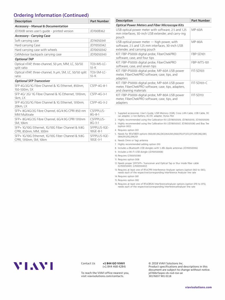
Ordering Information (Continued)Description Part NumberAccessory - Manual & DocumentationJD700B series user's guide - printed version JD700B362Accessory - Carrying CaseSoft carrying case JD74050341Hard carrying Case JD71050342Hard carrying case with wheels JD70050342CellAdvisor backpack carrying case JD70050343Optional TAPOptical nTAP, three-channel, 50 µm, MM, LC, 50/50 split ratio
TO3-M5-LC-55-K
Optical nTAP, three-channel, 9 µm, SM, LC, 50/50 split ratio
TO3-SM-LC-55-K
Optional SFP TransceiverSFP 4G/2G/1G Fibre Channel & 1G Ethernet, 850nm, 150-500m, SX
CSFP-4G-8-1
SFP 4G/ 2G/ 1G Fibre Channel & 1G Ethernet, 1310nm, 5km, LX
CSFP-4G-3-1
SFP 4G/2G/1G Fibre Channel & 1G Ethernet, 1310nm, 20km, LX
CSFP-4G-3-2
SFP+ 8G/4G/2G Fibre Channel, 6G/4.9G CPRI 850 nm MM Multirate
CSFPPLUS-8G-8-1
SFP+ 8G/4G/2G Fibre Channel, 6G/4.9G CPRI 1310nm SM, 10km
CSFPPLUS-8G-3-1
SFP+ 1G/10G Ethernet, 1G/10G Fiber Channel & 9.8G CPRI, 850nm, MM, 300m
SFPPLUS-1GE-10GE-8-1
SFP+ 1G/10G Ethernet, 1G/10G Fiber Channel & 9.8G CPRI, 1310nm, SM, 10km
SFPPLUS-1GE-10GE-3-1
Description Part NumberOptical Power Meters and Fiber Microscope KitsUSB optical power meter with software, 2.5 and 1.25 mm interfaces, 30-inch USB extender, and carry-ing pouch
MP-60A
USB optical power meter — high power, with software, 2.5 and 1.25 mm interfaces, 30-inch USB extender, and carrying pouch
MP-80A
KIT: FBP-P5000i digital probe, FiberChekPRO software, case, and four tips
FBP-SD101
KIT: FBP-P5000i digital probe, FiberChekPRO software, case, and seven tips
FBP-MTS-101
KIT: FBP-P5000i digital probe, MP-60A USB power meter, FiberChekPRO software, case, tips, and adapters
FIT-SD103
KIT: FBP-P5000i digital probe, MP-60A USB power meter, FiberChekPRO software, case, tips, adapters, and cleaning materials
FIT-SD103-C
KIT: FBP-P5000i digital probe, MP-80A USB power meter, FiberChekPRO software, case, tips, and adapters
FIT-SD113
1. Supplied accessories: User’s Guide, USB Memory (1GB), Cross LAN Cable, USB Cable, DC car adapter, Li-Ion Battery, AC/DC adapter, Stylus Pen
2. Highly recommended using the Calibration Kit (JD78050509, JD78050510, JD70050509)3. Highly recommended using the Calibration Kit (JD78050507, JD78050508) and Bias Tee
(option 002)4. Requires option 0015. Needs for RFoFIBER options 060,061,062,063,064,065,068,070,071,072,073,081,082,083,
084,091,092,096,1016. Needs Omni or Yagi antenna7. Highly recommended adding option 0108. Includes a Bluetooth USB dongles with 5 dBi dipole antennas (JD70050006)9. Includes a Wi-Fi USB dongle (JD70050008)10. Requires G70005038011. Requires option 00812. Needs proper SFP/SFP+ Transceiver and Optical Tap or thur mode fiber cable
(G700050401, G700050402)13. Requires at least one of RFoCPRI Interference Analyzer options (option 060 to 065),
needs each of the respective/corresponding Interference Analyzer line rate14. Requires option 08115. Requires option 08216. Requires at least one of RFoOBSAI InterferenceAnalyzer options (option 070 to 073),
needs each of the respective/corresponding InterferenceAnalyzer line rate