vib3.doc
TRANSCRIPT

7/27/2019 vib3.doc
http://slidepdf.com/reader/full/vib3doc 1/17
5. VIBRATION DUE TO MECHANICAL LOOSENESS
There are three distinct types of Mechanical looseness. They are,
- Looseness of structure/base frame- Looseness related to pedestal cracks
- Looseness related the rotor
Mechanical looseness amplifies the amplitudes due to exciting forces
already present in the machine. Mechanical looseness is due to loss of or
reduction in stiffness.
5.1 Looseness of structure/base frame
Weakness/looseness of the machine feet, base plate and concrete base,
deteriorated grouting, distortion of the structure or base frame and loose
hold down bolts are some of the structural related problems causing
vibration.
5.1.1 Identifying Structure related vibration
- Vibration is characterized by dominant 1XRPM amplitude.
- Phase behaviour is a local phenomenon pertaining to driver or
the driven equipment.
- Highly directional vibration.
- Phase angle difference between horizontal and vertical
directions will be 0 or 180 degrees.
The symptoms are similar to that of vibration due to eccentricity.
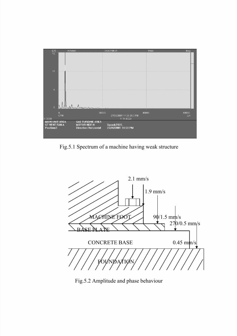
Spectrum taken from a machine having soft foot has been shown in
Fig.5.1. Notice the dominant 1XRPM vibration peak in the spectrum. The
problem is confirmed by carrying out phase analysis. The variouselements of a rigidly held structure will move together. In case of any
looseness, there will be relative motion at the interface resulting in
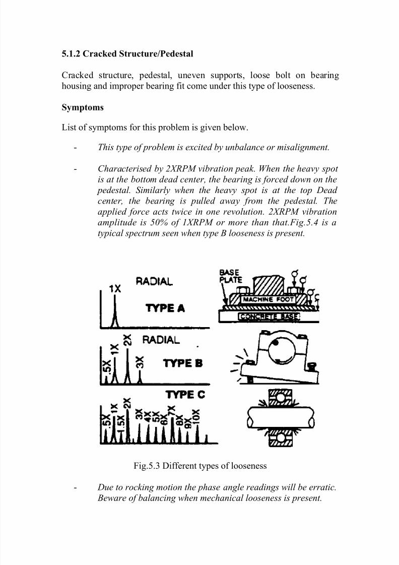
loss of amplitude and phase angle changes. In Fig.5.2 is shown a case
of weak base plate. A phase change of 180 degrees at the interface
between the base plate and the concrete base indicates a weak base plate.
7/27/2019 vib3.doc
http://slidepdf.com/reader/full/vib3doc 2/17
Fig.5.1 Spectrum of a machine having weak structure
2.1 mm/s
1.9 mm/s
MACHINE FOOT 90/1.5 mm/s
270/0.5 mm/s
BASE PLATE
CONCRETE BASE 0.45 mm/s
FOUNDATION
Fig.5.2 Amplitude and phase behaviour
7/27/2019 vib3.doc
http://slidepdf.com/reader/full/vib3doc 3/17
5.1.2 Cracked Structure/Pedestal
Cracked structure, pedestal, uneven supports, loose bolt on bearing
housing and improper bearing fit come under this type of looseness.
Symptoms
List of symptoms for this problem is given below.
- This type of problem is excited by unbalance or misalignment.
- Characterised by 2XRPM vibration peak. When the heavy spot
is at the bottom dead center, the bearing is forced down on the
pedestal. Similarly when the heavy spot is at the top Dead
center, the bearing is pulled away from the pedestal. Theapplied force acts twice in one revolution. 2XRPM vibration
amplitude is 50% of 1XRPM or more than that.Fig.5.4 is a
typical spectrum seen when type B looseness is present.
Fig.5.3 Different types of looseness
- Due to rocking motion the phase angle readings will be erratic.
Beware of balancing when mechanical looseness is present.
7/27/2019 vib3.doc
http://slidepdf.com/reader/full/vib3doc 4/17
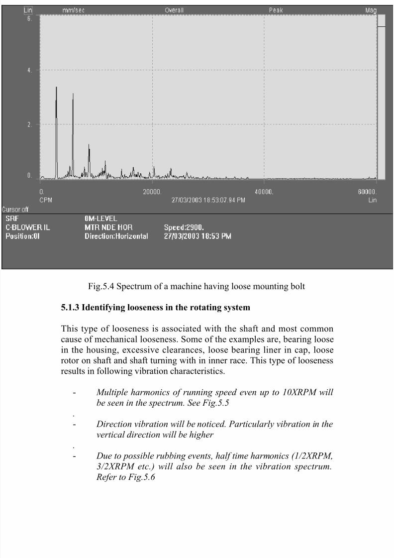
Fig.5.4 Spectrum of a machine having loose mounting bolt
5.1.3 Identifying looseness in the rotating system
This type of looseness is associated with the shaft and most common
cause of mechanical looseness. Some of the examples are, bearing loose
in the housing, excessive clearances, loose bearing liner in cap, loose
rotor on shaft and shaft turning with in inner race. This type of looseness
results in following vibration characteristics.
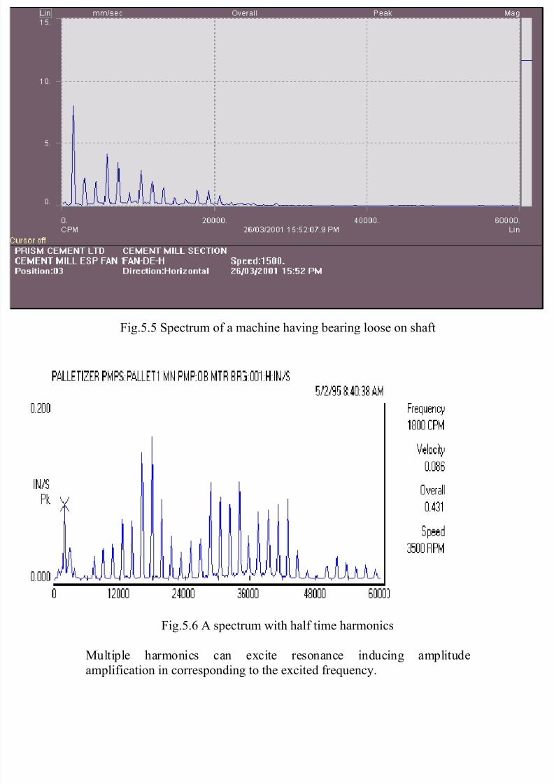
- Multiple harmonics of running speed even up to 10XRPM will be seen in the spectrum. See Fig.5.5
.
- Direction vibration will be noticed. Particularly vibration in the
vertical direction will be higher
.
- Due to possible rubbing events, half time harmonics (1/2XRPM,
3/2XRPM etc.) will also be seen in the vibration spectrum.
Refer to Fig.5.6
7/27/2019 vib3.doc
http://slidepdf.com/reader/full/vib3doc 5/17
Fig.5.5 Spectrum of a machine having bearing loose on shaft
Fig.5.6 A spectrum with half time harmonics
Multiple harmonics can excite resonance inducing amplitude
amplification in corresponding to the excited frequency.
7/27/2019 vib3.doc
http://slidepdf.com/reader/full/vib3doc 6/17
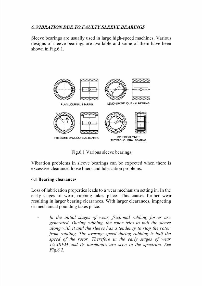
6. VIBRATION DUE TO FAULTY SLEEVE BEARINGS
Sleeve bearings are usually used in large high-speed machines. Various
designs of sleeve bearings are available and some of them have been
shown in Fig.6.1.
Fig.6.1 Various sleeve bearings
Vibration problems in sleeve bearings can be expected when there is
excessive clearance, loose liners and lubrication problems.
6.1 Bearing clearances
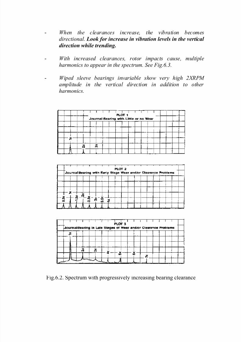
Loss of lubrication properties leads to a wear mechanism setting in. In the
early stages of wear, rubbing takes place. This causes further wear
resulting in larger bearing clearances. With larger clearances, impactingor mechanical pounding takes place.
- In the initial stages of wear, frictional rubbing forces are
generated. During rubbing, the rotor tries to pull the sleeve
along with it and the sleeve has a tendency to stop the rotor
from rotating. The average speed during rubbing is half the
speed of the rotor. Therefore in the early stages of wear
1/2XRPM and its harmonics are seen in the spectrum. See
Fig.6.2.
7/27/2019 vib3.doc
http://slidepdf.com/reader/full/vib3doc 7/17
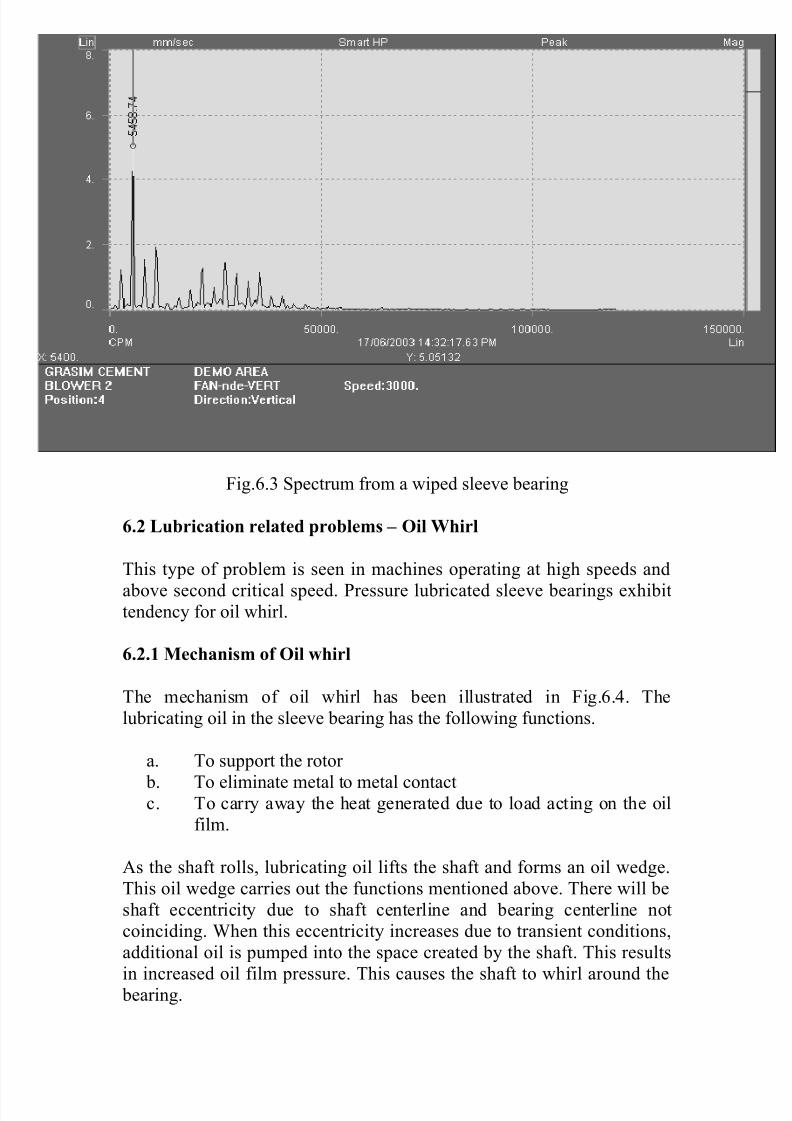
- When the clearances increase, the vibration becomes
directional. Look for increase in vibration levels in the vertical
direction while trending.
- With increased clearances, rotor impacts cause, multipleharmonics to appear in the spectrum. See Fig.6.3.
- Wiped sleeve bearings invariable show very high 2XRPM
amplitude in the vertical direction in addition to other
harmonics.
Fig.6.2. Spectrum with progressively increasing bearing clearance
7/27/2019 vib3.doc
http://slidepdf.com/reader/full/vib3doc 8/17
Fig.6.3 Spectrum from a wiped sleeve bearing
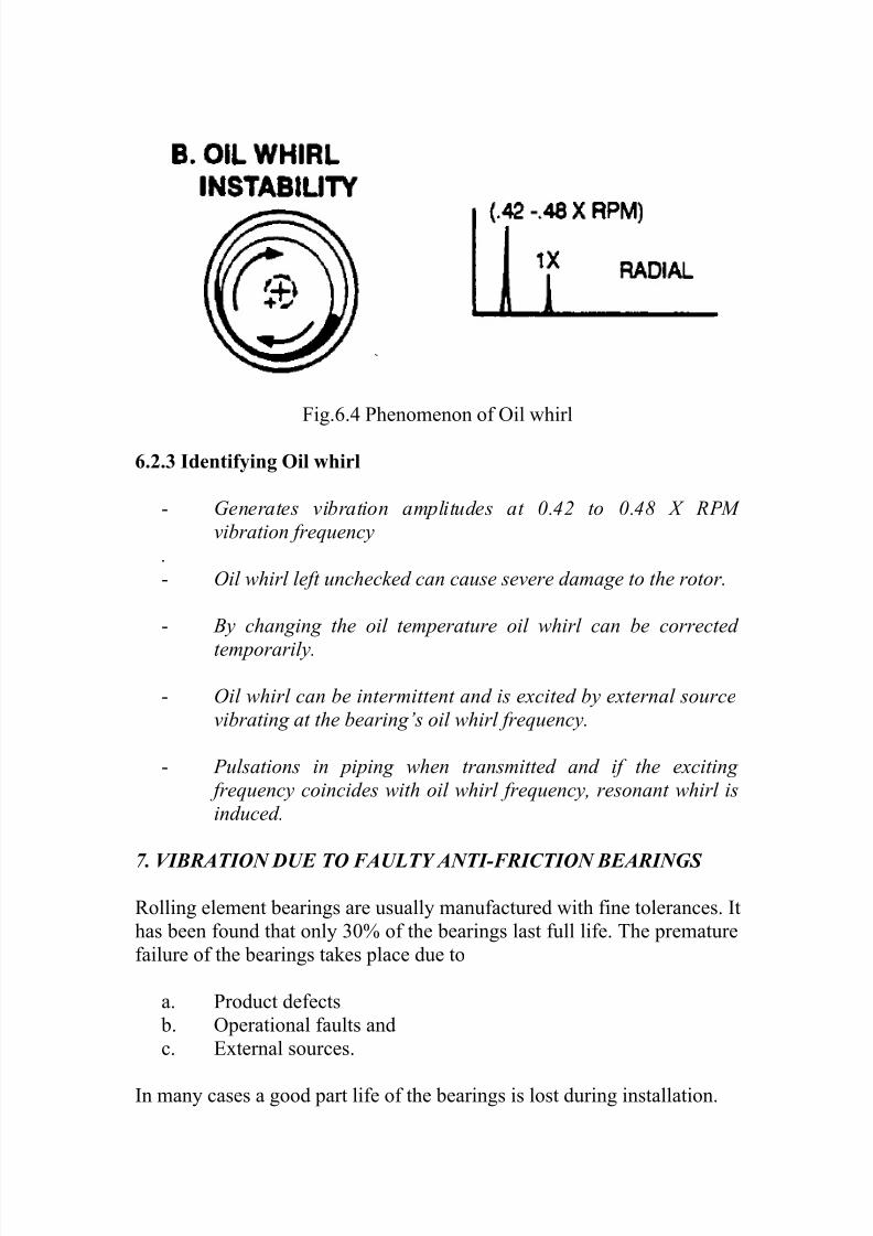
6.2 Lubrication related problems – Oil Whirl
This type of problem is seen in machines operating at high speeds and
above second critical speed. Pressure lubricated sleeve bearings exhibittendency for oil whirl.
6.2.1 Mechanism of Oil whirl
The mechanism of oil whirl has been illustrated in Fig.6.4. The
lubricating oil in the sleeve bearing has the following functions.
a. To support the rotor
b. To eliminate metal to metal contactc. To carry away the heat generated due to load acting on the oil
film.
As the shaft rolls, lubricating oil lifts the shaft and forms an oil wedge.
This oil wedge carries out the functions mentioned above. There will be
shaft eccentricity due to shaft centerline and bearing centerline not
coinciding. When this eccentricity increases due to transient conditions,
additional oil is pumped into the space created by the shaft. This results
in increased oil film pressure. This causes the shaft to whirl around the bearing.
7/27/2019 vib3.doc
http://slidepdf.com/reader/full/vib3doc 9/17
Fig.6.4 Phenomenon of Oil whirl
6.2.3 Identifying Oil whirl
- Generates vibration amplitudes at 0.42 to 0.48 X RPM
vibration frequency
.
- Oil whirl left unchecked can cause severe damage to the rotor.
- By changing the oil temperature oil whirl can be corrected
temporarily.
- Oil whirl can be intermittent and is excited by external source
vibrating at the bearing’s oil whirl frequency.
- Pulsations in piping when transmitted and if the exciting
frequency coincides with oil whirl frequency, resonant whirl is
induced.
7. VIBRATION DUE TO FAULTY ANTI-FRICTION BEARINGS
Rolling element bearings are usually manufactured with fine tolerances. It
has been found that only 30% of the bearings last full life. The premature
failure of the bearings takes place due to
a. Product defects
b. Operational faults and
c. External sources.
In many cases a good part life of the bearings is lost during installation.
7/27/2019 vib3.doc
http://slidepdf.com/reader/full/vib3doc 10/17
Commonly known causes for bearing failure are, excessive load,
misalignment, Defective seating, faulty mounting, improper lubrication,
poor sealing, false brinellling and electric current.
7.1 Nature of rolling element-bearing vibration
- Defects in the rolling element bearings cause high frequency
low amplitude vibrations.
- The bearing vibration defect frequencies are not integral
multiples of Shaft speed.
- The bearing vibration is generally confined to the nearest point.
- The vibration frequencies generated are ultrasonic
frequencies, natural frequencies of the bearing components,
defect frequencies based on the geometry of the bearing and
sum and difference frequencies.
7.2 Bearing Failure stages
Bearings have been known to go through different stages of failure,
before terminal failure occurs. By identifying these stages during
vibration trending in addition to avoiding breakdowns, bearing could be
made to last longer.
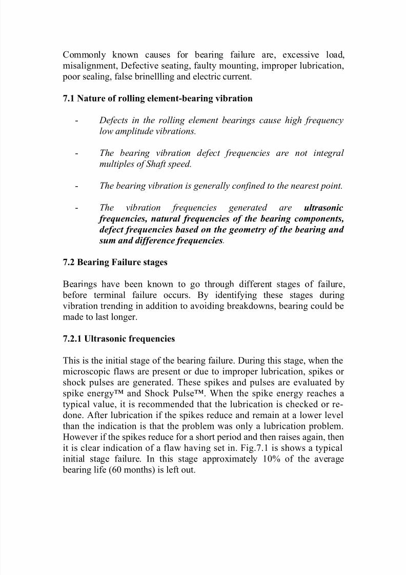
7.2.1 Ultrasonic frequencies
This is the initial stage of the bearing failure. During this stage, when the
microscopic flaws are present or due to improper lubrication, spikes or
shock pulses are generated. These spikes and pulses are evaluated by
spike energy™ and Shock Pulse™. When the spike energy reaches a
typical value, it is recommended that the lubrication is checked or re-done. After lubrication if the spikes reduce and remain at a lower level
than the indication is that the problem was only a lubrication problem.
However if the spikes reduce for a short period and then raises again, then
it is clear indication of a flaw having set in. Fig.7.1 is shows a typical
initial stage failure. In this stage approximately 10% of the average
bearing life (60 months) is left out.
7/27/2019 vib3.doc
http://slidepdf.com/reader/full/vib3doc 11/17
Spikes/pulses (0.25 gSE)
Fig.7.1 Ultrasonic frequencies
Fig. 7.1a Spike energy spectrum of lubrication problem
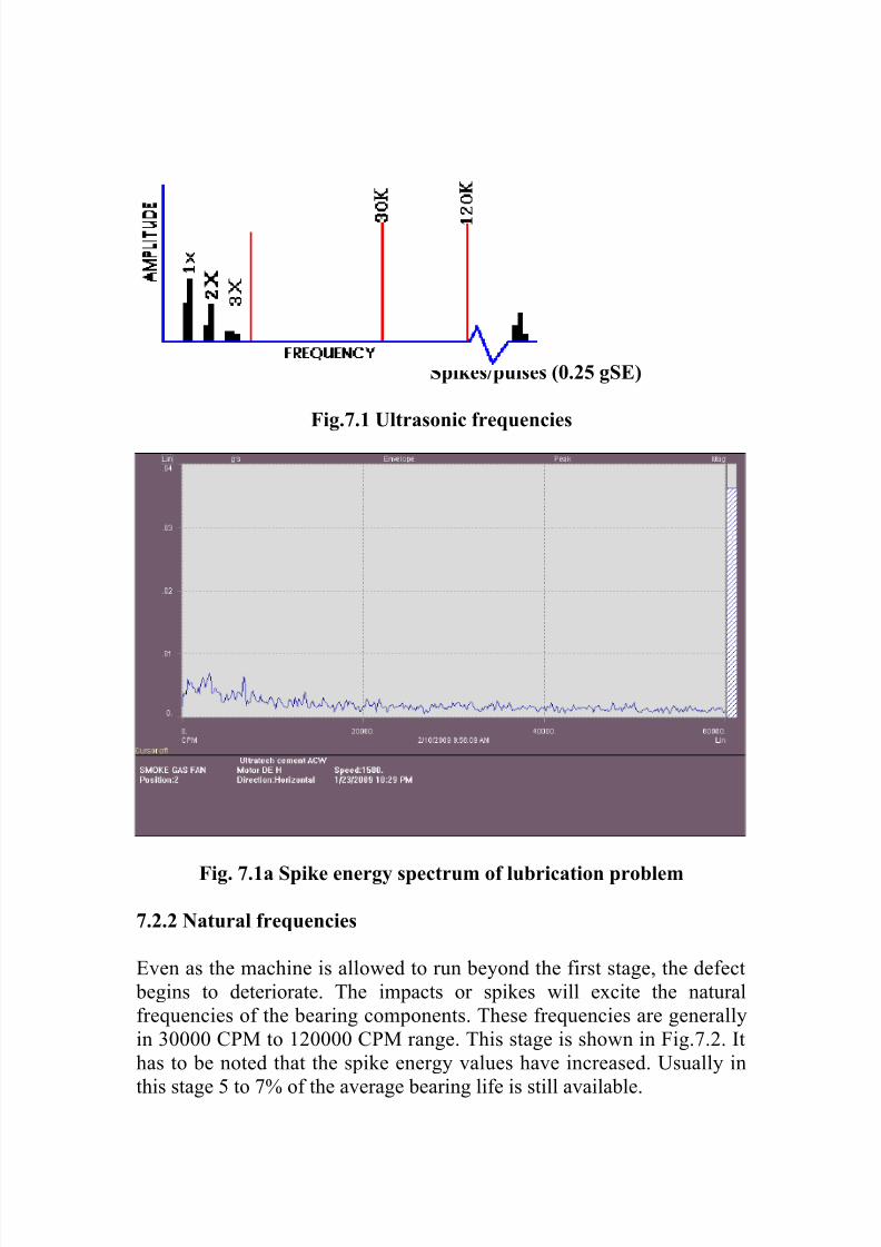
7.2.2 Natural frequencies
Even as the machine is allowed to run beyond the first stage, the defect
begins to deteriorate. The impacts or spikes will excite the natural
frequencies of the bearing components. These frequencies are generally
in 30000 CPM to 120000 CPM range. This stage is shown in Fig.7.2. It
has to be noted that the spike energy values have increased. Usually in
this stage 5 to 7% of the average bearing life is still available.
7/27/2019 vib3.doc
http://slidepdf.com/reader/full/vib3doc 12/17
Spike/shock pulse (.25 to .5 gSE)
Fig.7.2 Natural frequencies of bearing components
Fig.7.2a Natural frequencies of bearing components
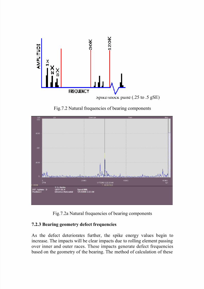
7.2.3 Bearing geometry defect frequencies
As the defect deteriorates further, the spike energy values begin to
increase. The impacts will be clear impacts due to rolling element passing
over inner and outer races. These impacts generate defect frequencies
based on the geometry of the bearing. The method of calculation of these
7/27/2019 vib3.doc
http://slidepdf.com/reader/full/vib3doc 13/17
frequencies is shown in Table 7.1. The appearance of the defect
frequencies in the spectrum is shown in Fig.7.3.
Usually the amplitude corresponding to defect frequency of the defective
part grows. Sometimes defects in the cage appear in the spectrum more asa side band frequency than a carrier frequency. In this stage the spike
energy value increases from 0.5 gSE to 1 gSE. 2 to 5% of the bearing life
remains in this stage. It is only during this stage defects in the bearing
could be visible for naked eye.
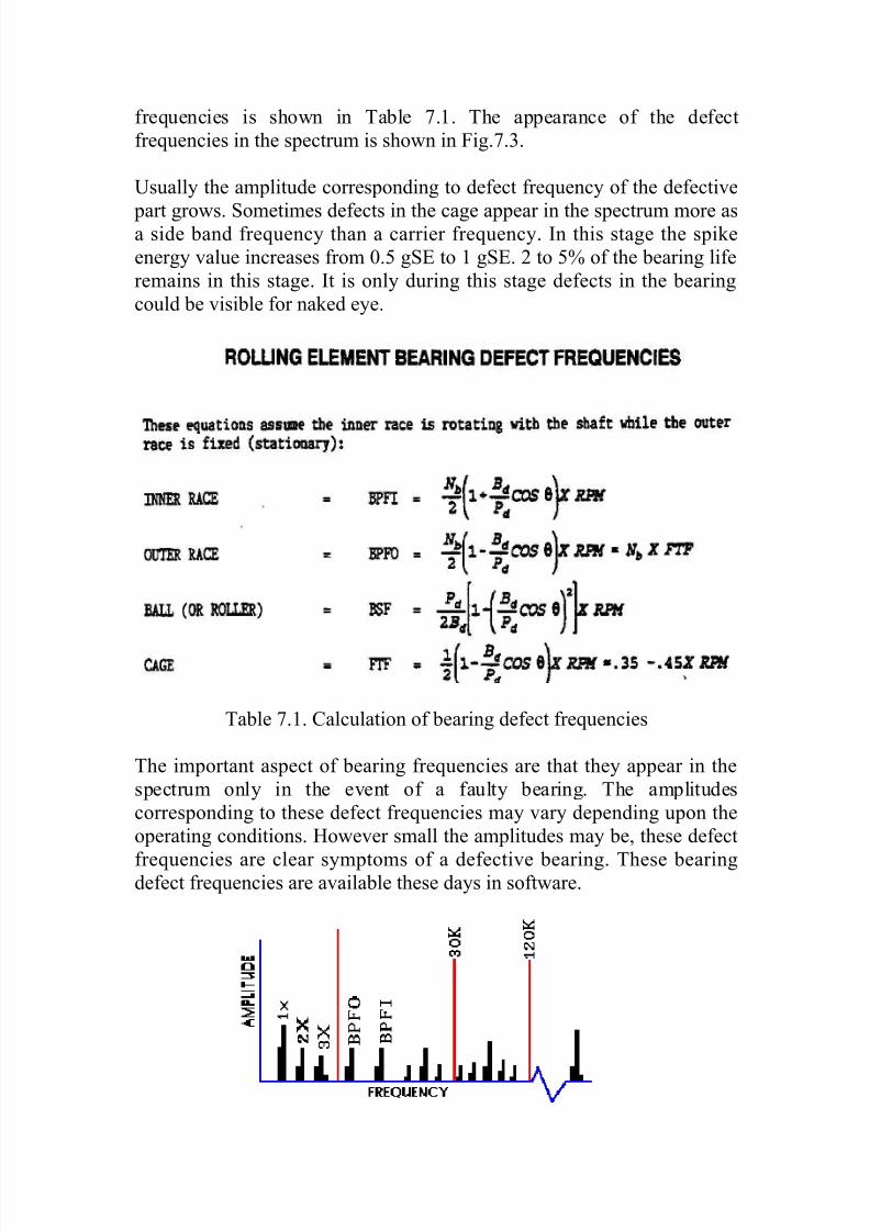
Table 7.1. Calculation of bearing defect frequencies
The important aspect of bearing frequencies are that they appear in the
spectrum only in the event of a faulty bearing. The amplitudes
corresponding to these defect frequencies may vary depending upon the
operating conditions. However small the amplitudes may be, these defect
frequencies are clear symptoms of a defective bearing. These bearingdefect frequencies are available these days in software.

7/27/2019 vib3.doc
http://slidepdf.com/reader/full/vib3doc 14/17
Spikes and pulses (0.5 to 1 gSE)
Fig.7.3 Third stage of bearing failure
Fig.7.3A third stage of failure
7.2.4 Bearing gives way
Towards the end of the third stage of bearing failure, harmonics of the
bearing defect frequencies are noticed. It will be desirable to increase the
number of surveys on the machine and closely monitor the vibration
levels. The rate of failure from the end of third stage to terminal failure is
unpredictable. It is recommended that an indent be made for replacement
of bearing at the end of the third stage.
While monitoring the spikes closely, there will a point when the spikessuddenly drop. The machine should be shutdown and bearing replaced at
this point of time. The typical spectrum is shown in Fig.7.4. Notice the
broadband random noise. If the machine is allowed to run beyond this, it
will cause seizure.

7/27/2019 vib3.doc
http://slidepdf.com/reader/full/vib3doc 15/17
Spikes an Pulses (sudden drop)
Fig.7.4 Last stage of bearing failure
7.2.5 Guidelines for determining bearing failures
In machines without previous history, the relationship between the spikes
and bearing failure can be established by experience. The Table 7.3
indicates the measurement patterns for such evaluation.
VIBRATION LEVELS
Disp Vel Accl SpikesMachine condition
Machine Ok Ok Ok Ok OK
Watch M/c
Bearing
defects
OK to run
Ok Ok Ok High
Watch M/c
Bearing
defectsOK to run
Ok Ok High High
Machine
ProblemsOk High High High
Machine
problemsHigh High High High
Table 7.2 Guideline for measurements for bearing defects

7/27/2019 vib3.doc
http://slidepdf.com/reader/full/vib3doc 16/17
When a bearing fails, different physical changes are seen in the bearing.
The Table 7.3 indicates the effects of such physical changes and the
causes along with remarks. It is recommended that the bearing removed
from the machine be inspected. This is to serve as guideline for finding
root cause failures.
From the foregoing discussions on vibration due to faulty rolling element
bearings, it could be seen that monitoring and trending the bearing
vibration, maximum life of the bearing could be extracted. Usually
permitted values of spike energy are shown in Table 7.3.
Enveloped spectrum and spike energy spectrums are used these days to to
detect early, rotational frequencies. The method is shown in Fig.7.5
Effect Cause Remarks
Surface Fatigue
Smearing
Scoring
Debris denting
Overheating
Lubrication problem Low viscosity
Roller bearing having
high thrust load
Foreign matter causing
dents
Friction from race
turning on shaft
Spalling Improper fit
Defective seats
Cracking and flaking
of race
Abrasion
Corrosion
Debris denting
Over heating
Poor sealing Dirt entering during
installation.
Moisture carried by air
Damage to raceways Unbalance
Misalignment
Typically damage ininner race
Typically damage in
outer race
Grooves in raceways
Fractures
Retainer failure
Misalignment Due to overloading
fractures result
Brinelling Background vibration
Shock loads
Poor mounting
High static impact load
Severe vibration of a
machine at rest

7/27/2019 vib3.doc
http://slidepdf.com/reader/full/vib3doc 17/17
Table 7.3 Effect and Cause of bearing defects
Initial Value Maximum Value
Ball bearings
Fig.7.5 Enveloping process
TIME BANDPASS
FILTER
TIME
ENVELOPER
TIME FAST
FOURIER
TRANSFORM
SPECTRUM
BDF