vibracon mini lvl-ah -...
TRANSCRIPT
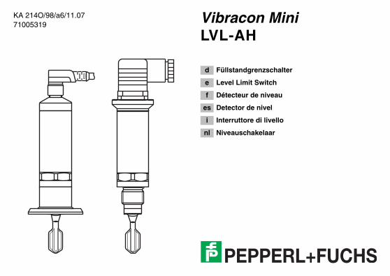
KA 214O/98/a6/11.0771005319
Vibracon MiniLVL-AH
d Füllstandgrenzschalter
e Level Limit Switch
f Détecteur de niveau
es Detector de nivel
i Interruttore di livello
nl Niveauschakelaar
2
d InhaltSicherheitshinweise 4Geräte-Identifikation 6Behandlung 8Einbaubeispiele 10Einbau 12Anschluss DC-PNP 18Anschluss AC 22Anschluss AC-i-Bus 24Test 25Reinigung 26Technische Daten 27Zubehör, Ersatzteile 29Fehlersuche 33Ergänzende Dokumentation
39
Achtung!= verboten; führt zu fehlerhaftem Betrieb oder Zerstörung.
e ContentsNotes on safety 4Device identification 6Handling 8Mounting examples 10Installation 12Connection DC-PNP 18Connection AC 22Connection AC-i-Bus 24Test 25Cleaning 26Technical data 27Accessories, Spare parts 29Trouble-shooting 34Supplementary documentation
39
Caution!= forbidden; leads to incorrect operation or
destruction.
f SommaireConseils de sécurité 4Désignation de l´appareil 6Manipulation 8Exemples d’implantation 10Montage 12Raccordement DC-PNP 18Raccordement AC 22Raccordement AC-i-Bus 24Test 25Nettoyage 26Caractéristiques techniques
27
Accessoires, Pièces de rechange
29
Recherche de défauts 35Documentation complémentaire
39
Attention != interdit; peut provoquer des dysfonctionnements ou la destruction.
3
es IndiceNotas sobre seguridad 5Identificación del equipo 6Modo de empleo 8Ejemplos de montaje 10Montaje 12Conexiones DC-PNP 18Conexiones AC 22Conexiones AC-i-Bus 24Combración 25Limpieza 26Datos técnicos 27Accesorios, Repuestos 29Identificación de fallos 36Documentación suplementaria
39
¡Atención!= Prohibido; peligro de mal funcionamiento o de destrucción.
i IndiceNote sulla sicurezza 5Identificazione dello strumento
6
Accorgimenti 8Esempi di montaggio 10Montaggio 12Collegamenti DC-PNP 18Collegamenti AC 22Collegamenti AC-i-Bus 24Test 25Pulizia 26Dati tecnici 27Accessori, Ricambi 29Individuazione e eliminazione delle anomalie
37
Documentazione supplementare
39
Attenzione!= Vietato; pericolo di malfunzionamento o di
distruzione.
nl InhoudVeiligheidsinstructies 5Instrument-identificatie 6Behandeling 8Inbouwvoorbelden 10Inbouw 12Aansluiting DC-PNP 18Aansluiting AC 22Aansluiting AC-i-Bus 24Test 25Reiniging 26Technische gegevens 27Toebehoren, Reserve-onderdelen
29
Fout zoeken 38Aanvullende documentatie
39
Opgelet!= verboden; leidt tot foutieve werking of storing.
4
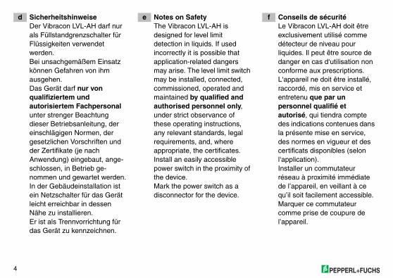
d SicherheitshinweiseDer Vibracon LVL-AH darf nur als Füllstandgrenzschalter für Flüssigkeiten verwendet werden.Bei unsachgemäßem Einsatz können Gefahren von ihm ausgehen.Das Gerät darf nur von qualifiziertem und autorisiertem Fachpersonal unter strenger Beachtung dieser Betriebsanleitung, der einschlägigen Normen, der gesetzlichen Vorschriften und der Zertifikate (je nach Anwendung) eingebaut, ange-schlossen, in Betrieb ge-nommen und gewartet werden.In der Gebäudeinstallation ist ein Netzschalter für das Gerät leicht erreichbar in dessen Nähe zu installieren.Er ist als Trennvorrichtung für das Gerät zu kennzeichnen.
e Notes on SafetyThe Vibracon LVL-AH is designed for level limit detection in liquids. If used incorrectly it is possible that application-related dangers may arise. The level limit switch may be installed, connected, commissioned, operated and maintained by qualified and authorised personnel only, under strict observance of these operating instructions, any relevant standards, legal requirements, and, where appropriate, the certificates.Install an easily accessible power switch in the proximity of the device.Mark the power switch as a disconnector for the device.
f Conseils de sécuritéLe Vibracon LVL-AH doit être exclusivement utilisé comme détecteur de niveau pour liquides. Il peut être source de danger en cas d‘utilisation non conforme aux prescriptions. L‘appareil ne doit être installé, raccordé, mis en service et entretenu que par un personnel qualifié et autorisé, qui tiendra compte des indications contenues dans la présente mise en service, des normes en vigueur et des certificats disponibles (selon l‘application).Installer un commutateur réseau à proximité immédiate de l’appareil, en veillant à ce qu’il soit facilement accessible.Marquer ce commutateur comme prise de coupure de l’appareil.
5
es Notas sobre seguridadEl detector de nivel Vibracon LVL-AH ha sido diseñado para la detección de límite en fluidos. Su empleo inapropiado puede resultar peligroso. El equipo deberá ser montado, conectado, instalado y mantenido única y exclusivamente por personal cualificado y autorizado, bajo rigurosa observación de las presentes instrucciones de servicio, de las normativas y legislaciones vigentes, así como de los certificados (dependiendo de la aplicación).Instalar un interruptor de fácil acceso en las proximidades del equipo.Identificar el interruptor como desconectador del equipo.
i Note sulla sicurezzaIl Vibracon LVL-AH è particolarmente studiato per l'impiego come soglia di livello in liquidi. Un‘installazione non corretta può determinare pericolo. Lo strumento può essere montato solamente da personale qualificato ed autorizzato. Il montaggio, il collegamento, la messa in esercizio e la manutenzione devono rispettare le presenti istruzioni, le norme vigenti e i certificati (a seconda dell'applicazione).Installare un interruttore di alimentazione di facile accesso nelle vicinanze dello strumento. Contrassegnare l'interruttore di alimentazione come interruttore di disattivazione dello strumento.
nl VeiligheidsinstructiesGebruik de Vibracon LVL-AH alléén als niveauschakelaar voor vloeistoffen. Indien niet correct gebruikt kunnen gevaarlijke situaties ontstaan.Het instrument alleen door gekwalificeerd en geautoriseerd personeel laten inbouwen, aansluiten, in bedrijf nemen en onderhouden. Neem de instructies in deze Inbedrijfstellingsvoorschrif-ten, de desbetreffende normen, de wettelijke voorschriften en eventuele certificaten in acht.Installeer een makkelijk bereikbare voedingschakelaar in de nabijheid van het instrument. Kenmerk de voedingschakelaar specifiek voor het instrument.
6
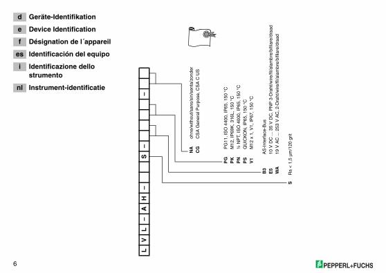
d Geräte-Identifikation
e Device Identification
f Désignation de l´appareil
es Identificación del equipo
i Identificazione dello strumento
nl Instrument-identificatie
LV
L–
AH
–S
––
NA
ohne
/with
out/s
ans/
sin/
sent
a/zo
nder
CG
CS
A G
ener
al P
urpo
se, C
SA
C U
S
PG
PG
11, I
SO
440
0, IP
65, 1
50 °
CP
KM
12, I
P69
K, 3
16L,
150
°C
PN
½ N
PT,
ISO
400
0, IP
65, 1
50 °
CP
SQ
UIC
KO
N, I
P65
, 150
°C
V1
M12
x 1
, V1,
IP67
, 150
°C
B3
AS
-Int
erfa
ce-B
usE
510
V D
C ..
. 35
V D
C, P
NP
3-D
raht
/wire
/fil/a
lam
bre/
bifil
are/
draa
dW
A19
V A
C ..
. 253
V A
C, 2
-Dra
ht/w
ire/fi
l/ala
mbr
e/bi
filar
e/dr
aad
SR
a <
1,5
µm
/120
grit
7
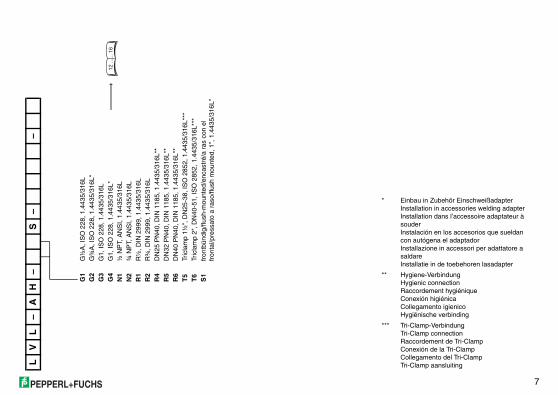
LV
L–
AH
–S
––
G1
G½
A, I
SO
228
, 1.4
435/
316L
G2
G¾
A, I
SO
228
, 1.4
435/
316L
*G
3G
1, IS
O 2
28, 1
.443
5/31
6LG
4G
1, IS
O 2
28, 1
.443
5/31
6L*
N1
½ N
PT,
AN
SI,
1.44
35/3
16L
N2
¾ N
PT,
AN
SI,
1.44
35/3
16L
R1
R½
, DIN
299
9, 1
.443
5/31
6LR
2R
¾, D
IN 2
999,
1.4
435/
316L
R4
DN
25 P
N40
, DIN
118
5, 1
.443
5/31
6L**
R5
DN
32 P
N40
, DIN
118
5, 1
.443
5/31
6L**
R6
DN
40 P
N40
, DIN
118
5, 1
.443
5/31
6L**
T5
Tric
lam
p 1½
", D
N25
-38,
ISO
285
2, 1
.443
5/31
6L**
*T
6Tr
icla
mp
2", D
N40
-51,
ISO
285
2, 1
.443
5/31
6L**
*S
1fr
ontb
ündi
g/flu
sh-m
ount
ed/e
ncas
tré/
a ra
s co
n el
fr
onta
l/pre
ssat
o a
raso
/flus
h m
ount
ed, 1
", 1
.443
5/31
6L*
12 ..
.... 1
6
* Einbau in Zubehör EinschweißadapterInstallation in accessories welding adapterInstallation dans l’accessoire adaptateur à souderInstalación en los accesorios que sueldan con autógena el adaptadorInstallazione in accessori per adattatore a saldareInstallatie in de toebehoren lasadapter
** Hygiene-VerbindungHygienic connectionRaccordement hygiéniqueConexión higiénicaCollegamento igienicoHygiënische verbinding
*** Tri-Clamp-VerbindungTri-Clamp connectionRaccordement de Tri-ClampConexión de la Tri-ClampCollegamento del Tri-ClampTri-Clamp aansluiting
8
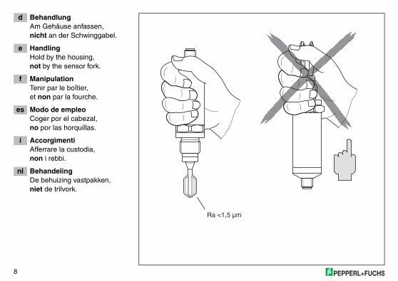
d BehandlungAm Gehäuse anfassen,nicht an der Schwinggabel.
e HandlingHold by the housing,not by the sensor fork.
f ManipulationTenir par le boîtier,et non par la fourche.
es Modo de empleoCoger por el cabezal,no por las horquillas.
i AccorgimentiAfferrare la custodia,non i rebbi.
nl BehandelingDe behuizing vastpakken,niet de trilvork.
Slave Profil Slave Profil
ENDRESS+LIQUIPHANENDRESS+LIQUIPHAN
FTL20H- XX FTL20H- XXAS-i AS-iSer.-No.:XXXXXXXXSer.-No.:XXXXXXXX
Made in Germany,D-79689 MaulburgMade in Germany,D-79689 Maulburg
OFF OFF
ONON
Ra <1,5 µm
9
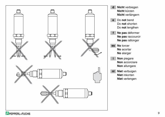
d Nicht verbiegenNicht kürzenNicht verlängern
e Do not bendDo not shortenDo not lengthen
f Ne pas déformerNe pas raccourcirNe pas rallonger
es No torcerNo acortarNo alargar
i Non piegareNon accorciareNon allungare
nl Niet verbuigenNiet inkortenNiet verlengen
10
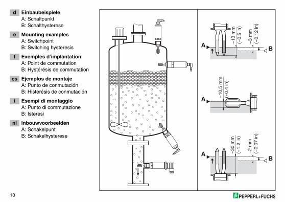
d EinbaubeispieleA: SchaltpunktB: Schalthysterese
e Mounting examplesA: SwitchpointB: Switching hysteresis
f Exemples d’implantationA: Point de commutationB: Hystérésis de commutation
es Ejemplos de montajeA: Punto de conmutaciónB: Histerésis de conmutación
i Esempi di montaggioA: Punto di commutazioneB: Isteresi
nl InbouwvoorbeeldenA: SchakelpuntB: Schakelhysterese
A B
B
~13
mm
(~0.
5 in
)
~3
mm
(~0.
12 in
)~
2 m
m(~
0.07
in)
~30
mm
(~1.
2 in
)
A
A
~10
,5 m
m(~
0.4
in)
11
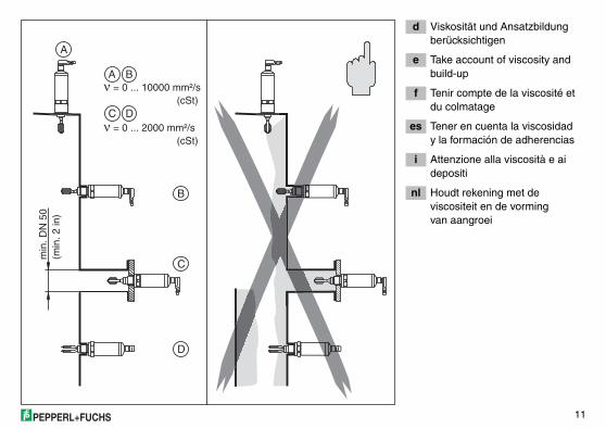
d Viskosität und Ansatzbildung berücksichtigen
e Take account of viscosity and build-up
f Tenir compte de la viscosité et du colmatage
es Tener en cuenta la viscosidady la formación de adherencias
i Attenzione alla viscosità e aidepositi
nl Houdt rekening met de viscositeit en de vormingvan aangroei
B
D
A
C
A
B
C
min
. DN
50
(min
. 2 in
)
D
ν = 0 ... 10000 mm²/s (cSt)
ν = 0 ... 2000 mm²/s (cSt)

12
d EinbauProzessanschlussG½A, G¾A, G1A(DIN ISO 228/1)
e InstallationProcess connectionG½A, G¾A, G1A(DIN ISO 228/1)
f MontageRaccord processusG½A, G¾A, G1A(DIN ISO 228/1)
es MontajeConexión a procesoG½A, G¾A, G1A(DIN ISO 228/1)
i MontaggioAttacco al processoG½A, G¾A, G1A(DIN ISO 228/1)
nl InbouwProcesaansluitingG½A, G¾A, G1A(DIN ISO 228/1)
32
2)
1)
KA 032O
G1
KA 219O
G¾
32 mm
EinschweißmuffeWeld-in socketManchon à souderManguito soldadoAttacco a saldareInlassok
max. 150 ˚C/25 bar(max. 423 K/360 psi)
max. 100 ˚C/40 bar(max. 373 K/580 psi)
32
G¾ => 1) ~63,9 mm/~2.6 in 2) ~ 38,0 mm/~1.5 inG1 => 1) ~78,0 mm/~3.7 in 2) ~ 48,0 mm/~1.9 in
13
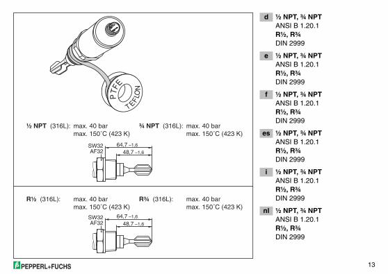
d ½ NPT, ¾ NPTANSI B 1.20.1R½, R¾DIN 2999
e ½ NPT, ¾ NPTANSI B 1.20.1R½, R¾DIN 2999
f ½ NPT, ¾ NPTANSI B 1.20.1R½, R¾DIN 2999
es ½ NPT, ¾ NPTANSI B 1.20.1R½, R¾DIN 2999
i ½ NPT, ¾ NPTANSI B 1.20.1R½, R¾DIN 2999
nl ½ NPT, ¾ NPTANSI B 1.20.1R½, R¾DIN 2999
PTF
E
T EFLO
N
¾ NPT (316L): max. 40 barmax. 150˚C (423 K)
R¾ (316L): max. 40 barmax. 150˚C (423 K)
½ NPT (316L): max. 40 barmax. 150˚C (423 K)
R½ (316L): max. 40 barmax. 150˚C (423 K)
64,7 –1,6
48,7 –1,6SW32AF32
64,7 –1,6
48,7 –1,6SW32AF32
14
d A: Prozessanschluss Triclamp 1½", 2" (ISO 2852)
B: HygieneverbindungDN 25, 32, 40 (DIN 11851)
e A: Process connectionTriclamp 1½", 2" (ISO 2852),
B: Hygienic connectionDN 25, 32, 40 (DIN 11851)
f A: Raccord processusTriclamp 1½", 2" (ISO 2852),
B: Raccordement hygiéniqueDN 25, 32, 40 (DIN 11851)
es A: Conexión a procesoTriclamp 1½", 2" (ISO 2852),
B: Conexión higiénicaDN 25, 32, 40 (DIN 11851)
i A: Attacco al processoTriclamp 1½", 2" (ISO 2852),
B: Collegamento igienicoDN 25, 32, 40 (DIN 11851)
nl A: ProcesaansluitingTriclamp 1½", 2" (ISO 2852),
B: Hygiënische verbindingDN 25, 32, 40 (DIN 11851)
47,9 mm(~1.9 in)
47,9 mm(~1.9 in)
max. 120 °C/16 bar
max. 150 °C/2 bar
(max. 393 K/230 psi)
max. 100 °C/40 barDN 25, DN 32, DN 40:
(max. 373 K/580 psi)
max. 140 °C/25 barDN 50:
(max. 413 K/360 psi)
max. 140 °C/25 bar(max. 413 K/360 psi)
(max. 423 K/29 psi)
A
B
15
d Prozessanschlussfür ausrichtbaren Einschweissadapter 1"
e Process connectionfor alignable weld-in adapter 1"
f Raccord processuspour adaptateur à souder 1" orientable
es Conexión a procesopara adaptador soldado orientable de 1"
i Attacco al processoper adattatore a saldare orientabile
nl Procesaansluitingvoor 1" inlassok die kan worden uitgericht
47,9mit Silikondichtung undÜberwurfmutter
with silicone seal andcoupling nut
avec joint silicone et écrou raccord
con junta de silicona y tuerca de unión
con guarnizione al siliconee dado per raccordi
met siliconenafdichting ensok
max. 100 °C
max. 150 °C
max. 40 bar(max. 373 Kmax. 580 psi)
max. 25 bar(max. 423 Kmax. 360 psi)
EHEDG
16
d Schwinggabel ausrichtenMarkierung beachten
e Align sensor forkNote mark
f Orienter la fourcheTenir compte du repère
es Orientación de las horquillas Atención a la marca
i Orientare il rebbioOsservare il contrassegno
nl Trilvork uitrichtenLet op de markering
ν > 2000 mm²/s
ν = 0 … 10000 mm²/s !
OFF
ON
OF
F
ON
17
d AnschlussStecker M12 x 1
e ConnectionPlug M12 x 1
f RaccordementPrise M12 x 1
es ConexionesEnchufe M12 x 1
i CollegamentoSpina M12 x 1
nl AansluitingStop M12 x 1
Nummer = Kleur Numero = ColoreNúmero = ColorNuméro = CouleurNumber = ColourNummer = Farbe
1 = BN = braun/brown/brun/marron/marrone/bruin2 = WT = weiß/white/blanc/blanco/bianco/wit3 = BU = blau/blue/bleu/azul/blu/blauw4 = BK = schwarz/black/noir/negro/nero/zwart
ye 1
ye 2 gn
18
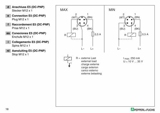
d Anschluss E5 (DC-PNP)Stecker M12 x 1
e Connection E5 (DC-PNP)Plug M12 x 1
f Raccordement E5 (DC-PNP)Prise M12 x 1
es Conexiones E5 (DC-PNP)Enchufe M12 x 1
i Collegamento E5 (DC-PNP)Spina M12 x 1
nl Aansluiting E5 (DC-PNP)Stop M12 x 1
externe belastingcarico esternocarga exterioncharge externeexternal loadexterne LastR =
I
MAX MIN
0,5 A
L– L+
R0,5 A
L– L+
2(WT)
1(BN)
3(BU)
4(BK)
2(WT)
1(BN)
3(BU)
4(BK)
R
I max. 250 mAU – 10 V ... 35 V...
19
d Funktion
e Function
f Fonction
es Funcionamiento
i Funzione
nl Functie
leuchtet/lights up/allumé/iluminado/acceso/aan
blinkt/flashes/clignote/parpadea/lampeggia/knippert
aus/off/éteint/apagado/spendo/uit
StoringGuastoFalloDéfautFaultStörung
+ +
1 1 1 (3/2) (3/2)12 2 4 (2/3) (2/3)4
1 2 1 2 1 41 4
gn rdye
ye 1
ye 2 gn
(PNP)
N L–
0 V
UMAX MINL1 L+
L+ L+ L+ L+ L+L+
< 3 V < 3 V
∆U < 100 µA < 100 µA < 100 µA∆U
– – – – ––
II III
U– (DC)...
20
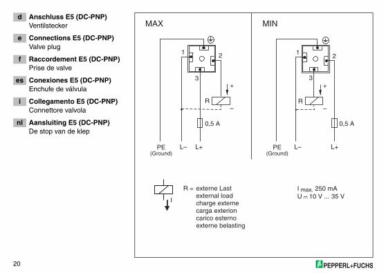
d Anschluss E5 (DC-PNP)Ventilstecker
e Connections E5 (DC-PNP)Valve plug
f Raccordement E5 (DC-PNP)Prise de valve
es Conexiones E5 (DC-PNP)Enchufe de válvula
i Collegamento E5 (DC-PNP)Connettore valvola
nl Aansluiting E5 (DC-PNP)De stop van de klep
externe belastingcarico esternocarga exterioncharge externeexternal loadexterne LastR =
I
MAX MIN
I max. 250 mAU – 10 V ... 35 V...
(Ground) (Ground)
1
3
0,5 A
L– L–L+ L+PE PE
2
+
–R
3
0,5 A
1 2
+
–R
21
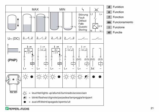
d Funktion
e Function
f Fonction
es Funcionamiento
i Funzione
nl Functie
3 3 2 (3/2) (3/2)22 2 3 (2/3) (2/3)3
3 2 3 2 2 32 3
(PNP)
N L–
0 V
UMAX MIN
L1 L+
L+ L+ L+ L+ L+L+
< 3 V < 3 V
∆U < 100 µA < 100 µA < 100 µA∆U
– – – – ––
II III
gn rd
U– (DC)...
+ +
= leuchtet/lights up/allumé/iluminado/acceso/aan
= blinkt/flashes/clignote/parpadea/lampeggia/knippert
= aus/off/éteint/apagado/spento/uit
StoringGuastoFalloDéfautFaultStörung
22
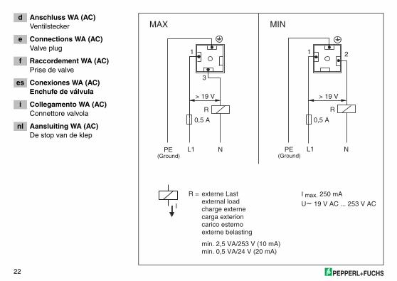
d Anschluss WA (AC)Ventilstecker
e Connections WA (AC)Valve plug
f Raccordement WA (AC)Prise de valve
es Conexiones WA (AC)Enchufe de válvula
i Collegamento WA (AC)Connettore valvola
nl Aansluiting WA (AC)De stop van de klep
externe belastingcarico esternocarga exterioncharge externeexternal loadexterne LastR =
I
MAX MIN
I max. 250 mA
U~ 19 V AC ... 253 V AC
(Ground)
1
3
R
0,5 A
L1 NPE
> 19 V
(Ground)
1 2
R
0,5 A
L1 NPE
> 19 V
min. 2,5 VA/253 V (10 mA)min. 0,5 VA/24 V (20 mA)
23
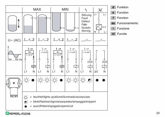
d Funktion
e Function
f Fonction
es Funcionamiento
i Funzione
nl Functie
50 ... 60 Hz
L1 L1 L1 L1 L1L1
< 12 V < 12 V
< 4 mA < 4 mA < 4 mA
N N N N NN
1 1 1 1 113 3 2 (3/2) (3/2)2
U~ (AC) 1 3 1 3 1 21 2
gn rd
N L–
0 V
UMAX MINL1 L+
= leuchtet/lights up/allumé/iluminado/acceso/aan
= blinkt/flashes/clignote/parpadea/lampeggia/knippert
= aus/off/éteint/apagado/spento/uit
StoringGuastoFalloDéfautFaultStörung
∆U ∆U
II III
24
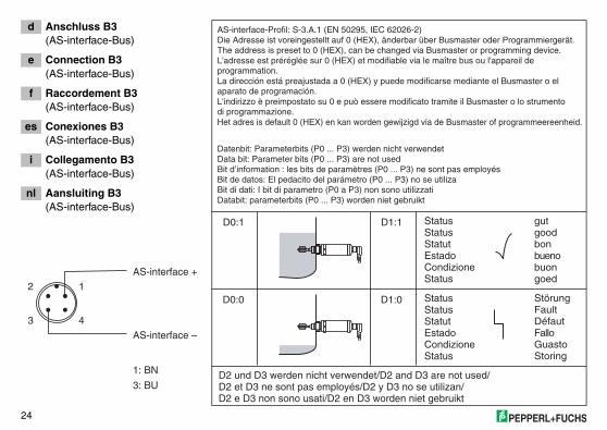
d Anschluss B3(AS-interface-Bus)
e Connection B3(AS-interface-Bus)
f Raccordement B3(AS-interface-Bus)
es Conexiones B3(AS-interface-Bus)
i Collegamento B3(AS-interface-Bus)
nl Aansluiting B3(AS-interface-Bus)
D0:1 D1:1
D0:0 D1:0
D2 und D3 werden nicht verwendet/D2 and D3 are not used/D2 et D3 ne sont pas employés/D2 y D3 no se utilizan/D2 e D3 non sono usati/D2 en D3 worden niet gebruikt
AS-interface-Profil: S-3.A.1 (EN 50295, IEC 62026-2)
Storing
Het adres is default 0 (HEX) en kan worden gewijzigd via de Busmaster of programmeereenheid.
Databit: parameterbits (P0 ... P3) worden niet gebruikt
Guasto
L'indirizzo è preimpostato su 0 e può essere modificato tramite il Busmaster o lo strumentodi programmazione.
Bit di dati: I bit di parametro (P0 a P3) non sono utilizzati
Fallo
La dirección está preajustada a 0 (HEX) y puede modificarse mediante el Busmaster o el aparato de programación.
Bit de datos: El pedacito del parámetro (P0 ... P3) no se utiliza
Défaut
L'adresse est préréglée sur 0 (HEX) et modifiable via le maître bus ou l'appareil de programmation.
Bit d’information : les bits de paramètres (P0 ... P3) ne sont pas employés
Fault
The address is preset to 0 (HEX), can be changed via Busmaster or programming device.
Data bit: Parameter bits (P0 ... P3) are not used
Störung
Die Adresse ist voreingestellt auf 0 (HEX), änderbar über Busmaster oder Programmiergerät.
Datenbit: Parameterbits (P0 ... P3) werden nicht verwendet
goedbuonbuenobongoodgut
StatusCondizioneEstadoStatutStatusStatus
StatusCondizioneEstadoStatutStatusStatus
AS-interface +
AS-interface –
2 1
3 4
1: BN
3: BU
25
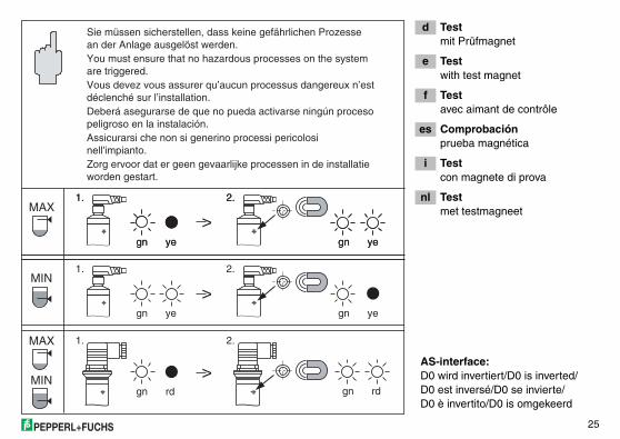
d Testmit Prüfmagnet
e Testwith test magnet
f Testavec aimant de contrôle
es Comprobaciónprueba magnética
i Testcon magnete di prova
nl Testmet testmagneet
Zorg ervoor dat er geen gevaarlijke processen in de installatieworden gestart.
Assicurarsi che non si generino processi pericolosi nell'impianto.
Deberá asegurarse de que no pueda activarse ningún procesopeligroso en la instalación.
Vous devez vous assurer qu’aucun processus dangereux n’estdéclenché sur l’installation.
You must ensure that no hazardous processes on the systemare triggered.
Sie müssen sicherstellen, dass keine gefährlichen Prozessean der Anlage ausgelöst werden.
MIN
gn gnye ye
gn gnye ye
>
1.
1.
2.
2.MAX
gn gnye ye
1. 2.
MAX
gngn rd rd
1. 2.
MIN
>
>AS-interface:D0 wird invertiert/D0 is inverted/D0 est inversé/D0 se invierte/D0 è invertito/D0 is omgekeerd
26
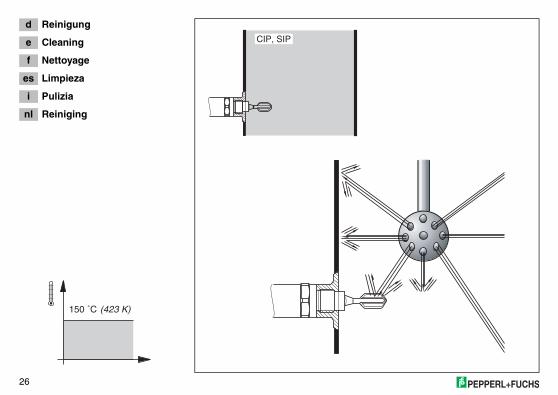
d Reinigung
e Cleaning
f Nettoyage
es Limpieza
i Pulizia
nl Reiniging
CIP, SIP
150 ˚C (423 K)
27
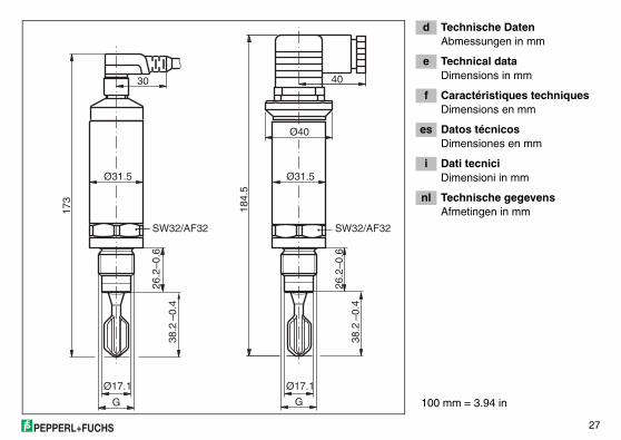
d Technische DatenAbmessungen in mm
e Technical dataDimensions in mm
f Caractéristiques techniquesDimensions en mm
es Datos técnicosDimensiones en mm
i Dati tecniciDimensioni in mm
nl Technische gegevensAfmetingen in mm
GG
173
4030
Ø40
Ø31.5
Ø17.1
SW32/AF32
184.
5
SW32/AF32
Ø17.1
Ø31.5
38.2
–0.4
38.2
–0.4
26.2
–0.6
26.2
–0.6
100 mm = 3.94 in
28
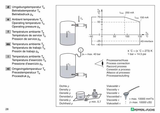
d Umgebungstemperatur TaBetriebstemperatur TbBetriebsdruck pe
e Ambient temperature TaOperating temperature TbOperating pressure pe
f Température ambiante TaTempérature de service TbPression de service pe
es Temperatura ambiente TaTemperatura de trabajo TbPresión de trabajo pe
i Temperatura ambiente TaTemperatura d’esercizio TbPressione d’esercizio pe
nl Omgevingstemperatuur TaPrecestemperatuur TbProcesdruk pe Procesaansuluiting
Dichtheid ρ Viskositeit ν
Attacco al processo
Densità ρ Viscosità ν
Conexión a proceso
Densidad ρ Viscosidad ν
Raccord process
Densité ρ Viscosité ν
Process connection
Density ρ Viscosity ν
Prozessanschluss
Dichte Viskositätρ ν
–40
0
–25
pe = max. 40 bar
50 100Tb
˚C
Tb
Tb
150
AS-interface
50
70
Ta
˚C
Ta
0
bar
I 250 mA
I 150 mA
max
max
–40
ρ min. 0,7ννmax. 10000 mm2/s
( max. 10000 cSt)
1l0,7kg
x ˚C = (x ˚C + 273) K1 bar = 14.5 psi
29
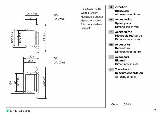
d ZubehörErsatzteileAbmessungen in mm
e AccessoriesSpare partsDimensions in mm
f AccessoiresPièces de rechangeDimensions en mm
es AccesoriosRepuestosDimensiones en mm
i AccessoriRicambiDimensioni in mm
nl ToebehorenReserve-onderdelenAfmetingen in mm
–0,4
Ø50
–0,4
21
26,1–0,2 Ø
32,2
G¾
IS
O 2
28
Ø60
–0,4
24,6
29,6
Ø41
G1
ISO
228
InlassokAttacco a saldareManguito soldadoManchon à souderWeld-in socketEinschweißmuffe
G¾
LVL-Z66
G1
LVL-Z101
100 mm = 3.94 in
30
d ZubehörErsatzteileAbmessungen in mm
e AccessoriesSpare partsDimensions in mm
f AccessoiresPièces de rechangeDimensions en mm
es AccesoriosRepuestosDimensiones en mm
i AccessoriRicambiDimensioni in mm
nl ToebehorenReserve-onderdelenAfmetingen in mm
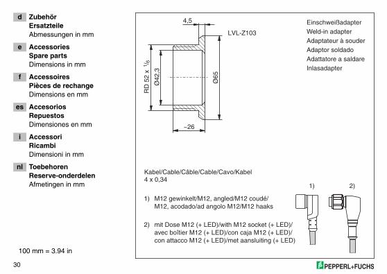
InlasadapterAdattatore a saldareAdaptor soldadoAdaptateur à souderWeld-in adapterEinschweißadapter4,5
~26
RD
52
x /1
6
Ø42
,3
Ø65
LVL-Z103
1) M12 gewinkelt/M12, angled/M12 coudé/ M12, acodado/ad angolo M12/M12 haaks
2) mit Dose M12 (+ LED)/with M12 socket (+ LED)/ avec boîtier M12 (+ LED)/con caja M12 (+ LED)/ con attacco M12 (+ LED)/met aansluiting (+ LED)
Kabel/Cable/Câble/Cable/Cavo/Kabel4 x 0,34
1) 2)
100 mm = 3.94 in
31
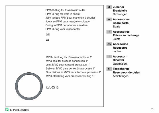
d ZubehörErsatzteileDichtungen
e AccessoriesSpare partsSeals
f AccessoiresPièces se rechangeJoints
es AccesoriosRepuestosJuntas
i AccessoriRicambiGuarnizioni
nl ToebehorenReserve-onderdelenAfdichtingen
FPM O-ring voor inlasadapter
MVQ-afdichting voor procesaansluiting 1"
O-ring in FPM per attacco a saldare
Guarnizione in MVQ per attacco al processo 1"
Junta en FPM para manguito soldado
Sello en MVQ para conexión a proceso 1"
Joint torique FPM pour manchon à souder
Joint MVQ pour raccord processus 1''
FPM O-ring for weld-in socket
MVQ seal for process connection 1"
FPM-O-Ring für Einschweißmuffe
MVQ-Dichtung für Prozessanschluss 1"
G¾
G1
LVL-Z113
32
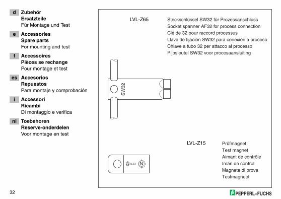
d ZubehörErsatzteileFür Montage und Test
e AccessoriesSpare partsFor mounting and test
f AccessoiresPièces se rechangePour montage et test
es AccesoriosRepuestosPara montaje y comprobación
i AccessoriRicambiDi montaggio e verifica
nl ToebehorenReserve-onderdelenVoor montage en test
Testmagneet
Pijpsleutel SW32 voor procesaansluiting
Magnete di prova
Chiave a tubo 32 per attacco al processo
Imán de control
Llave de fijación SW32 para conexión a proceso
Aimant de contrôle
Clé de 32 pour raccord processus
Test magnet
Socket spanner AF32 for process connection
Prüfmagnet
Steckschlüssel SW32 für Prozessanschluss
SW
32
NTEST
LVL-Z65
LVL-Z15
33
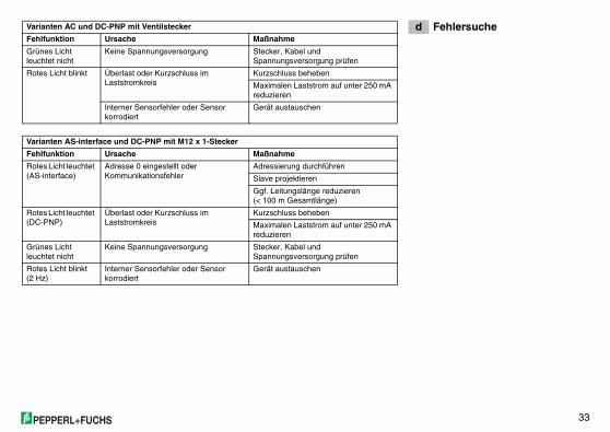
d FehlersucheVarianten AC und DC-PNP mit Ventilstecker
Fehlfunktion Ursache Maßnahme
Grünes Licht leuchtet nicht
Keine Spannungsversorgung Stecker, Kabel und Spannungsversorgung prüfen
Rotes Licht blinkt Überlast oder Kurzschluss im Laststromkreis
Kurzschluss beheben
Maximalen Laststrom auf unter 250 mA reduzieren
Interner Sensorfehler oder Sensor korrodiert
Gerät austauschen
Varianten AS-interface und DC-PNP mit M12 x 1-Stecker
Fehlfunktion Ursache Maßnahme
Rotes Licht leuchtet (AS-interface)
Adresse 0 eingestellt oder Kommunikationsfehler
Adressierung durchführen
Slave projektieren
Ggf. Leitungslänge reduzieren(< 100 m Gesamtlänge)
Rotes Licht leuchtet (DC-PNP)
Überlast oder Kurzschluss im Laststromkreis
Kurzschluss beheben
Maximalen Laststrom auf unter 250 mA reduzieren
Grünes Licht leuchtet nicht
Keine Spannungsversorgung Stecker, Kabel und Spannungsversorgung prüfen
Rotes Licht blinkt (2 Hz)
Interner Sensorfehler oder Sensor korrodiert
Gerät austauschen
34
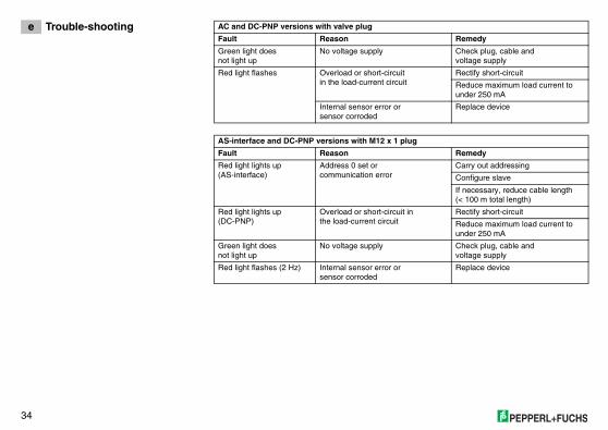
e Trouble-shooting AC and DC-PNP versions with valve plug
Fault Reason Remedy
Green light doesnot light up
No voltage supply Check plug, cable andvoltage supply
Red light flashes Overload or short-circuit in the load-current circuit
Rectify short-circuit
Reduce maximum load current to under 250 mA
Internal sensor error or sensor corroded
Replace device
AS-interface and DC-PNP versions with M12 x 1 plug
Fault Reason Remedy
Red light lights up(AS-interface)
Address 0 set or communication error
Carry out addressing
Configure slave
If necessary, reduce cable length (< 100 m total length)
Red light lights up(DC-PNP)
Overload or short-circuit inthe load-current circuit
Rectify short-circuit
Reduce maximum load current to under 250 mA
Green light doesnot light up
No voltage supply Check plug, cable andvoltage supply
Red light flashes (2 Hz) Internal sensor error orsensor corroded
Replace device
35
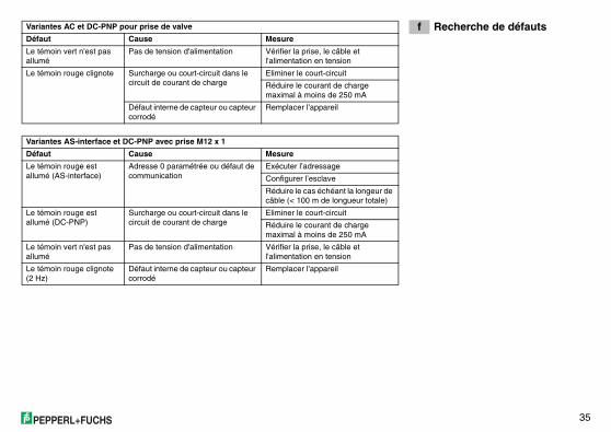
f Recherche de défautsVariantes AC et DC-PNP pour prise de valve
Défaut Cause Mesure
Le témoin vert n'est pas allumé
Pas de tension d'alimentation Vérifier la prise, le câble et l'alimentation en tension
Le témoin rouge clignote Surcharge ou court-circuit dans le circuit de courant de charge
Eliminer le court-circuit
Réduire le courant de charge maximal à moins de 250 mA
Défaut interne de capteur ou capteur corrodé
Remplacer l'appareil
Variantes AS-interface et DC-PNP avec prise M12 x 1
Défaut Cause Mesure
Le témoin rouge est allumé (AS-interface)
Adresse 0 paramétrée ou défaut de communication
Exécuter l’adressage
Configurer l’esclave
Réduire le cas échéant la longeur de câble (< 100 m de longueur totale)
Le témoin rouge est allumé (DC-PNP)
Surcharge ou court-circuit dans le circuit de courant de charge
Eliminer le court-circuit
Réduire le courant de charge maximal à moins de 250 mA
Le témoin vert n'est pas allumé
Pas de tension d'alimentation Vérifier la prise, le câble et l'alimentation en tension
Le témoin rouge clignote (2 Hz)
Défaut interne de capteur ou capteur corrodé
Remplacer l'appareil
36
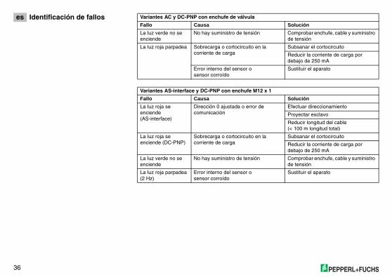
es Identificación de fallos Variantes AC y DC-PNP con enchufe de válvula
Fallo Causa Solución
La luz verde no se enciende
No hay suministro de tensión Comprobar enchufe, cable y suministro de tensión
La luz roja parpadea Sobrecarga o cortocircuito en la corriente de carga
Subsanar el cortocircuito
Reducir la corriente de carga por debajo de 250 mA
Error interno del sensor osensor corroído
Sustituir el aparato
Variantes AS-interface y DC-PNP con enchufe M12 x 1
Fallo Causa Solución
La luz roja se enciende (AS-interface)
Dirección 0 ajustada o error de comunicación
Efectuar direccionamiento
Proyectar esclavo
Reducir longitud del cable(< 100 m longitud total)
La luz roja se enciende (DC-PNP)
Sobrecarga o cortocircuito en la corriente de carga
Subsanar el cortocircuito
Reducir la corriente de carga por debajo de 250 mA
La luz verde no se enciende
No hay suministro de tensión Comprobar enchufe, cable y suministro de tensión
La luz roja parpadea (2 Hz)
Error interno del sensor osensor corroído
Sustituir el aparato
37
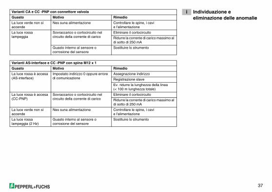
i Individuazione e eliminazione delle anomalie
Varianti CA e CC -PNP con connettore valvola
Guasto Motivo Rimedio
La luce verde non si accende
Nes suna alimentazione Controllare le spine, i cavi e l'alimentazione
La luce rossa lampeggia
Sovraccarico o cortocircuito nel circuito della corrente di carico
Eliminare il cortocircuito
Ridurre la corrente di carico massimo al di sotto di 250 mA
Guasto interno al sensore o corrosione del sensore
Sostituire lo strumento
Varianti AS-interface e CC -PNP con spina M12 x 1
Guasto Motivo Rimedio
La luce rossa è accesa (AS-interface)
Impostato indirizzo 0 oppure errore di comunicazione
Assegnazione indirizzo
Registrazione slave
Ev. ridurre la lunghezza della linea (< 100 m lunghezza totale)
La luce rossa è accesa (CC-PNP)
Sovraccarico o cortocircuito nel circuito della corrente di carico
Eliminare il cortocircuito
Ridurre la corrente di carico massimo al di sotto di 250 mA
La luce verde non si accende
Nes suna alimentazione Controllare le spine, i cavi e l'alimentazione
La luce rossa lampeggia (2 Hz)
Guasto interno al sensore o corrosione del sensore
Sostituire lo strumento
38
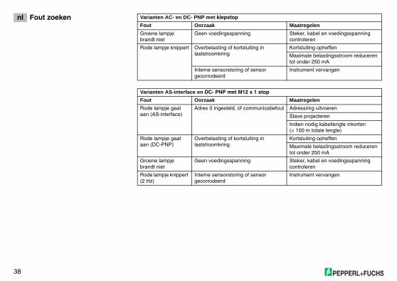
nl Fout zoeken4
Varianten AC- en DC- PNP met klepstop
Fout Oorzaak Maatregelen
Groene lampje brandt niet
Geen voedingsspanning Steker, kabel en voedingsspanning controleren
Rode lampje knippert Overbelasting of kortsluiting in laststroomkring
Kortsluiting opheffen
Maximale belastingsstroom reduceren tot onder 250 mA
Interne sensorstoring of sensor gecorrodeerd
Instrument vervangen
Varianten AS-interface en DC- PNP met M12 x 1 stop
Fout Oorzaak Maatregelen
Rode lampje gaat aan (AS-interface)
Adres 0 ingesteld, of communicatiefout Adressring uitvoeren
Slave projecteren
Indien nodig kabellengte inkorten(< 100 m totale lengte)
Rode lampje gaat aan (DC-PNP)
Overbelasting of kortsluiting in laststroomkring
Kortsluiting opheffen
Maximale belastingsstroom reduceren tot onder 250 mA
Groene lampje brandt niet
Geen voedingsspanning Steker, kabel en voedingsspanning controleren
Rode lampje knippert (2 Hz)
Interne sensorstoring of sensor gecorrodeerd
Instrument vervangen
39
d Ergänzende Dokumentation
e Supplementary documentation
f Documentation complémentaire
es Documentación adicional
i Documentazione supplementare
nl Aanvullende documentatie
Technische Information/Technical information/Information technique/Información técnica/Informazioni tecniche/Technische informatie
TI 379O
Betriebsanleitung/Operating instruction/Mise en service/Instrucciones de funcionamiento/Istruzioni operative/Inbedrijfstellingsvoorschrift
KA 186O PG11Ventilstecker/Valve plug/Prise de valve/Enchufe de válvula/Connettore valvola/De stop van de klep
KA 032O G1A(Einschweißmuffe/Weld-in socket/Manchon à souder/Manguito soldado/Tronchetto a saldare/Inlassok)
KA 219O G¾A(Einschweißmuffe/Weld-in socket/Manchon à souder/Manguito soldado/Tronchetto a saldare/Inlassok)
www.pepperl-fuchs.com
Serviceline process automationTel. +49 0621 776-2222 � Fax +49 0621 776-27-2222 �� E-Mail: [email protected]
�������� ���Pepperl+Fuchs Pte Ltd. � P+F Building18 Ayer Rajah Crescent � Singapore 139942Tel. +65 7799091 � Fax +65 8731637�� ��� ����������������������
�������� ���Pepperl+Fuchs Inc. � 1600 Enterprise ParkwayTwinsburg, Ohio 44087 � USATel. +1 330 4253555 � Fax +1 330 4254607�� ��� ����������������������
+49 0621 776-0 +49 0621 776-1000
71005319
KA 214O/98/a6/11.07, 71005319, FM7.0 188317 11/07 02