vibration monitoring and predictive maintenance solutions kit
TRANSCRIPT

Banner Engineering Corp. Vibration Monitoring Solutions Kit Quick Start Guide Page 1 214301 Rev. D
Vibration Monitoring and Predictive Maintenance Solutions Kit
The MultiHop version of the Vibration Solutions Kit provides visual status of up to 40 Banner vibration and temperature sensors that are wirelessly linked to the included DXM Wireless Controller. This provides a simple “Check Engine Light” of the asset being monitored. The added benefits of a MultiHop style Solutions Kit include longer range capabilities by using repeater radios, wiring multiple sensors to a single radio, and more vibration information available per sensor for advanced applications.
The program takes a data sample every five minutes from the vibration sensors and the software uses the raw data to detect whether an asset is running, create a baseline of the four vibration characteristics (RMS Velocity 10-1000 Hz on Z and X axis and RMS High Frequency Acceleration 1000-4000 Hz on Z and X axis), and generate warning and alarm thresholds for those characteristics. Only data from an operational asset is used to create the baselines or thresholds and only that data is used to trigger warnings or alarms. Data from assets that are not running/operational appear on the graphs but are not used in the analysis.
RMS Velocity identifies problems such as: imbalance, misalignment, looseness, and other low frequency machine issues.
RMS High Frequency Acceleration is used to indicate early bearing wear issues.
Solutions Kit Model Radio Frequency Units Contents
SolutionsKit9-Vibe-MH 900 MHz Imperial 10” Banner Touch Screen HMI with Ethernet connection DXM700-B1R2 or DXM700-B1R4 Wireless Controller 5-port Ethernet switch 14” x 12” Polycarbonate enclosure, DIN rails, and terminal blocks M12 power input connector This kit also requires a 24 V DC Class 2 (UL) or a Limited Power Source (LPS) (CE) power supply that is sold separately (Banner recommends model PSW-24-1 (FCC/CE) or model PSD-24-4 (FCC/CE) if you are powering additional indicator lights)
SolutionsKit9-Vibemetric-MH 900 MHz Metric
SolutionsKit2-Vibe-MH 2.4 GHz Imperial
SolutionsKit2-Vibemetric-MH 2.4 GHz Metric
To get started:
1. Connect and plug in the 24 V DC Class 2 or LPS power supply to the Solutions Kit to apply power to the radios.
2. Assign sensor Modbus IDs (page 2), bind the radios to the kit (page 3), and confirm your signal quality with a site survey (page 3).
3. After a radio is bound with a sensor attached, the system begins sampling data to create a baseline for that sensor.

Banner Engineering Corp. Vibration Monitoring Solutions Kit Quick Start Guide Page 2 214301 Rev. D
Home Screen The Home screen displays four “check engine” type icons that represent groups of 10 sensors/motors for a total of 40 motors. Each icon is a color-coded indication of the status of vibration/temperature Warnings (yellow) or Alarms (red), or wireless connection status No Alerts (green) or Node of Out of Sync (orange) within that group. Touch the icon to bring up the 10 individual icons that represent each sensors’ status. Touch the sensor status icons to view detailed data and alarm information for each sensor.
Touch the “X” button in the upper right hand corner of each icon to hide that group of sensors if they are not in use to prevent the connection status alerts for any sensors within that group from displaying. Use the button that appears after pressing the “X” button to unhide that group for future expansion. NOTE: In the MultiHop version, all but motor #1 start as hidden for program efficiency, only unhide sensors that have been added and are in the network.
The Settings button opens access to Radio binding, Radio site survey, Asset baselining, Log file downloads, and other settings.
Touch each asset group label to re-label the icon.
Assigning Sensor Modbus IDs To begin configuring the sensors, each sensor must have a Modbus Sensor ID assigned to it. Sensor Modbus IDs must be between 11-50. Each sensor ID corresponds to an individual sensor icon on the HMI, with ID 11 as Motor #1 and ID 50 as Motor #40. Sensor IDs don’t have to be assigned in order and sensor IDs can be skipped if the goal is to have smaller groups of sensors between the other four main icons on the home page.
To assign sensor IDs, use either the menu system or the configuration software.
To use the radio’s menu system, follow these steps. For VT1 sensors, use your M-H10 radio and for VT2 sensors, use one of many radio options, such as M-H, M-H2, etc.
1. Apply power to the radio and connect one sensor at a time. 2. Push button 1 (left) until *DVCFG appears then push button 2 (right). 3. Push button 1 until -S ADR appears and push button 2. 4. Push button 1 and wait for the radio to read the current sensor ID.
A three-digit value appears with the current sensor ID with a blinking cursor. 5. Use the left button to cycle the value from 0-9 and the right button to accept the value and move the
cursor to the next digit right. Assign a new sensor ID value to 11 through 50; do not repeat any previously used ID values.
6. Push and hold button 2 when done. The screen says SAVING. 7. To repeat for more sensors, unplug the sensor and plug in the next sensor and repeat steps 3 through 6
with a new device ID. 8. After you have finished, double-click button 2 to return to the main menu. 9. Connect all sensors to be attached to that radio.
To assign the IDs using the configuration software, use the Sensor Configuration Software with a computer and either the BWA-USB1WIRE-001 cable accessory for the VT1 sensor or the BWA-UCT-900 cable accessory for the VT2 sensor to connect the sensor to the tool.
Follow the instructions in the Sensor Configuration Software Instruction Manual to assign the Sensor Modbus ID to a value between 11 through 50.
Site Survey and Binding Screen Banner Wireless radios, such as the battery-powered H10 radio paired with VT1 Vibration and Temperature Sensors or any Banner MultiHop Radio with RS485 connected to VT2 Vibration and Temperature Sensors, must be bound to the DXM Wireless Controller inside the Solutions Kit to begin communicating.
Following the instructions below, the radios are assigned a Modbus slave ID and begin communicating with the DXM wirelessly. Radios and sensors are purchased separately and after they are combined, must be bound

Banner Engineering Corp. Vibration Monitoring Solutions Kit Quick Start Guide Page 3 214301 Rev. D
individually. A new radio and sensor can be added to the network at any time by using the binding procedure. Radios must be bound to IDs 51 through 110.
Use the site survey function to measure the signal strength of radios after the solutions kit and radios are installed. Line powered radios can be used as repeaters to improve signal connection between other nearby radios and the master radio inside the solutions kit. Battery-powered H10 radios should be configured to run only as slave radios in transparent mode (DIP switches 6 and 7 ON).
Bind the Radios 1. On the HMI screen, go to the Settings -> Site Survey & Binding screen. 2. Enter in the Modbus Slave ID next to the Binding rocker switch and tap that switch to turn it ON. 3. On the radio, enter binding mode.
• If your radio has rotary dials, set the rotary dials to the same slave ID value entered on the HMI by following the radio’s data sheet and then triple-click button 2 (right) to enter binding mode.
• If your radio does not have rotary dials, triple-click button 2 (right button). After the radio is bound, the LEDs stay solid momentarily, then flash four times. The radio automatically exits binding mode.
4. On the HMI screen, touch the binding rocker switch to turn the switch to OFF to take the DXM out of binding mode. After the DXM is out of binding mode, the indicator LED on the radio flickers green when it is in sync with the DXM.
5. Repeat steps 1 through 4 for as many radios as are needed for the network. Entering binding mode causes all radios to go out of sync until the DXM exits binding mode. The radios will sync to the DXM within a few seconds.
Network Reformation Use the Network Reformation rocker switch any time a sensor is moved from one radio to another to help the network reform without requiring a reboot. The switch will turn OFF when the reformation is complete.
Site Survey Signal Quality Check 1. On the HMI screen, enter in the Modbus Slave ID of the Radio (51-110) next to the Site Survey rocker
switch and tap that switch to turn it ON. A 15-second timer will appear next to the switch and count to 15. After the timer is complete (it may take longer depending on signal quality or if the radios are going through repeaters), the results of the site survey will appear in the Green, Yellow, Red, and Missed boxes. The results are shown as a percentage and add up to a total of 100.
2. Follow the interpreting section of the Conducting a Site Survey and Interpreting the Results technical note on bannerengineering.com to determine what your results mean for your application.

Banner Engineering Corp. Vibration Monitoring Solutions Kit Quick Start Guide Page 4 214301 Rev. D
Vibration Node Group Screens Each sensor group on the main page has a screen of 10 individual icons, one for each vibration sensor. These icons represent the status of the motor with colored icons shown below.
Touch any icon to bring up the individual sensor’s screen that includes graphs, raw data, and alert descriptions. (page 5)
Touch the “X” button in the upper right-hand corner of each icon to hide that sensor and prevent connection status alerts from that sensor from appearing on the main HMI screen. Use the button that appears after pressing the “X” button to unhide that group for future expansion. For example, Asset #8 is hidden in the sample screen.
Touch each asset label to re-label the icon. That label remains in non-volatile memory and appears on the sensor’s status screen, binding screen, site survey screen, and baselining screens.
A small green lamp in the bottom right corner of a sensor’s icon indicates when that sensor data is baselining. Only temperature warnings and alarms appear during the baselining phase. After baselining is complete, the threshold levels are established, and vibration alerts may begin to appear.
If a sensor appears out of sync (orange), that means the radio it is attached to is no longer in sync with the main controller. This may indicate you need to replace the battery in the radio or interference is preventing the radio from remaining in sync. After replacing the battery or improving the radio’s site survey results, use the network reformation button in the Site Survey & Binding (page 3).

Banner Engineering Corp. Vibration Monitoring Solutions Kit Quick Start Guide Page 5 214301 Rev. D
Individual Sensor Status Screen Selecting a sensor icon opens that sensor’s status screen. Use the Back button in the bottom left to return to the previous screen.
① - Select the Vibration Characteristic to graph raw data. Options include: Z-Axis Velocity, Z-Axis High Frequency Acceleration, X-Axis Velocity, and X-Axis High Frequency Acceleration. The bottom left of the screen shows a real-time readout of the selected characteristic. Velocity is displayed in in/s (mm/s for Vibemetric versions) and Acceleration is displayed in gs. Note: Velocity values of 6.5535 and/or acceleration values of 5.355 indicate a sensor error. The system ignores these data points to avoid affecting the saved baseline or trended data. The system will not baseline when the raw data values appear as those values. Contact Banner support for troubleshooting.
② - Select the Time Scale of the graph from 0.1 to 168 total hours (7 days). Use the arrow keys to scroll right or left to see different periods of the collected data. The graphing data loggers have a fixed number of data points and if using the DEMO MODE button on the Settings page, then the increased sampling rate reduces the number of data points available for viewing until those data points have rolled off the end of the timeline.
③ - Select the data Scale Maximum. For Acceleration, the range is 0.25g to 5g (g-force) and for Velocity, the range is 0.5 inches/second to 5 inches/second (10 mm/s to 60 mm/s for metric versions).
④ - The Current Alerts section shows any warnings or alarms based on the Axis, Vibration Characteristic, and type (Chronic or Acute) that the system is detecting. Acute alerts are those crossing the threshold for five samples in a row (or the user setting on the Settings screen) and Chronic alerts are when a 100 point moving average crosses the thresholds. Only data from an operational asset is used to calculate averages and alerts.
⑤ - Select Temperature to view the temperature graph over the selected time period. Directly above the button is the current temperature of the selected sensor. The readout color is white if it’s nominal, yellow if it’s in a warning state, and red if it’s in an alarm state. The warning and alarm temperature settings are 158 °F (70 °C) and 176 °F (80 °C) respectively. A raw temperature value of 327.67 indicates a sensor error. Contact Banner support for troubleshooting. In the upper right-hand corner of the screen is the Sensor’s Modbus slave ID and Radio slave ID to which the sensor is attached. This can be useful in finding which radio a sensor is connected to if the orange Out of Sync status icon appears. Signal quality or battery replacement may be necessary for a radio that loses connection status.

Banner Engineering Corp. Vibration Monitoring Solutions Kit Quick Start Guide Page 6 214301 Rev. D
Settings Screen Site Survey & Binding – Opens a screen to allow binding, site survey, and network reformation of each wireless Radio to the Solutions Kit.
HMI Options - Provides the ability to copy/manage HMI log files, HMI configuration for advanced options, functional HMI options, and an Icon Legend as well as a Graph Legend.
DEMO MODE – Use only for demonstration purposes when fast sampling is required. Demo mode enables a fast sampling mode on all the bound sensors, putting them and the HMI into a four-second sample rate for 10 minutes (status indicated by the green light within the button). Reduce the Baseline Samples to less than 30 for demonstration purposes. Using Demo Mode drains the battery faster and creates a larger log file that fills up memory quicker, so only use this mode when demonstrating the kit, not during standard operation. Always use the stop operation safely button on the HMI Options screen before powering down and especially if powering down after using the Demo Mode button.
Enable Sensor Discovery – Use in the following two situations: 1) Use when a sensor shows the orange “Out of Sync” icon to see if there was a signal interference issue that has since recovered. 2) Use after correcting a sensor out of sync error (battery replacement, signal adjustment, etc.) to begin sampling again or when a new sensor is added to an existing radio. The switch turns off when discovery is complete. When a sensor goes out of sync, the sensor is only checked again every four hours to keep timeouts down to a minimum.
Baseline Samples – The Solutions Kit takes a baseline of the first 300 running samples of an asset. This can be adjusted up or down by clicking on this numeric entry box to any desired sample. Samples are taken at a fixed five-minute interval.
Acute Alarm Samples – The default number of samples above the warning or alarm threshold before an alert is triggered is five consecutive samples. Use the numeric entry box to adjust the default value up or down.
Asset Baselining – Sensors bound into the system automatically begin baselining. This button opens a screen to enable creation of new baselines and thresholds of each sensor individually, displays the remaining samples in the current baseline, and allows manual threshold limits to be set for both vibration and temperature on each sensor.
Enable Password for Settings (Lvl 8) – Turn ON/OFF the switch to enable/disable a password to access the settings menu. The default password for User Level 8 is “88888888”. This can be modified by clicking the Password Table button and changing the password for level 8 to any password up to 9 numbers long.
Enable Cloud Pushing – Turn ON/OFF the switch to enable to the DXM to begin pushing data to a cloud webserver at 5-minute intervals. This requires additional set up and modification of the XML file in the DXM to point to the correct web server with the correct site ID. Cloud pushing also requires connecting the DXM to a local network via Ethernet or a separately sold cellular modem. DO NOT set the cloud push interval in the XML file as the script triggers the push.
Time until next sample (s) – Displays the time (in seconds) until the Solutions Kit samples data from all bound sensors and updates graphs and other visual indicators.

Banner Engineering Corp. Vibration Monitoring Solutions Kit Quick Start Guide Page 7 214301 Rev. D
Sensor (Asset) Baselining Screen After the sensor is installed and the system is powered on, the software automatically begins collecting data and determines if the asset is running.
The software generates a baseline and thresholds based on the first 300 data samples or about 24 hours of asset running time (unless modified on the Settings page).
When an asset is replaced, repaired, or has heavy maintenance done, create a new baseline. If the sensor is moved after the initial baseline is calculated, generate a new baseline.
1. Turn on baselining for the appropriate sensors if a new baseline needs to be generated. The initial baseline is generated any time a new sensor is connected to the system and begins sending data without the need to trigger these switches. The number of baseline samples remaining displays next to the ON/OFF switch. The baseline switch remains on during baselining and resets to off after the baseline is complete.
2. Use the tabs Assets #1-10, Assets #11-20, Assets #21-30, and Assets #31-40 to access baselining switches for sensors.
3. Use the corresponding Manual Warning & Alarm Adjustments button for each sensor to open an individual windowed screen where current baseline threshold settings are visible.
4. Touch the numeric entry box in any of the New Settings rows to manually enter a new value for any or all the warning or alarm thresholds, including temperature.
5. Set the vibration settings back to zero to use the original baseline setting. Temperature is not a baselined value so although it displays a baseline value, the value is for reference if the new setting is changed. Manually set the temperature back to the baseline setting by entering 158°F (70°C) for warning or 176°F (80°C) for alarm.

Banner Engineering Corp. Vibration Monitoring Solutions Kit Quick Start Guide Page 8 214301 Rev. D
HMI Options Menu Screen This screen provides some added HMI functionality along with an Icon Legend and a Graph Legend.
HMI System Setup – Enters HMI Panel Setup. Use for setting Time, Date, and Advanced Options. Entering this screen will clear any logged data from the graphs but will not clear any data saved to files.
Stop Operation Safely – Stops HMI operation safely without data corruption before you power off the HMI. Always use this button prior to powering down to avoid data file corruption. If a “Filed to write logged data to file” or “Failed to save” message appears this is due to a power during the saving process and will require the file from the day of the power down to be deleted under the HMI System Setup menu.
The HMI provides data logging of all the raw data, baselines and thresholds. This data is saved to a file every 30 minutes and a new file is generated every day and stored in monthly folders. The HMI has storage for about 45 days of log files. Below are some options for managing and retrieving those files:
Copy Log Files to USB Drive – Plug a USB drive into the back of the HMI and click here to select the log files or folders to copy.
Manually Delete Files Older than ‘X’ Days – Deletes files older than a specified number of days immediately. Use this option if the HMI is warning about an inability to save data or a lack of storage space. Shortening the auto delete days parameter may be necessary.
Auto Delete Files Older than ‘X’ Days –The HMI auto deletes files older than the selected number of days. Default is 30 days with a maximum of 45 days.
Restart HMI Application – Restarts the HMI application, which clears all graphed data but retains any saved logs.
Re-Initialize HMI Non Volatile on Restart – Flip the switch to ON before restarting the HMI to reinitialize default settings and labels.

Banner Engineering Corp. Vibration Monitoring Solutions Kit Quick Start Guide Page 9 214301 Rev. D
Advanced Options
Install a Warning/Alarm light indicator Add a tower light or indicator light (such as a K70, TL50, TL70, etc.) to the solution box for added local indications of all clear, warnings, or alarms. The DXM Wireless Controller uses PNP outputs with a maximum of 100 mA per output so an interposing relay may need to be added to accommodate higher amperage lights.
To install:
1. Carefully cut an appropriately sized hole in the box and mount the light accordingly. (Standard size is 30 mm diameter)
2. Wire DC ground to the light or an interposing relay from the bottom row of the gray two-row terminal blocks inside the Solutions Kit on the DIN rail adjacent to the DXM Controller.
3. Wire the input of the light or interposing relay to the DXM as follows: a. O1 – Pin 5 – indicates any sensor/asset in Alarm or Out of Sync condition b. O2 – Pin 6 – indicates any sensor/asset in Warning condition c. O3 – Pin 7 – indicates any sensor/asset in either Warning, Alarm, or Out of Sync condition d. O4 – Pin 8 – indicates no Warning or Alarms conditions exist
Additional Vibration Information The vibration solutions kit provides machine learning for baseline and alerting on RMS Velocity and High Frequency Acceleration for both the X and Z Axis. However, the vibration sensor contains many additional registers of vibration information that are stored in the local registers and can be polled by any host connected to the same network or the data can be sent to the cloud. Below is a register list of the additional available information.
Register Number Description 6141 + S × 10 Z Axis Peak Acceleration
6142 + S × 10 X Axis Peak Acceleration
6143 + S × 10 Z Axis Peak Velocity Frequency
6144 + S × 10 X Axis Peak Velocity Frequency
6145 + S × 10 Z Axis RMS Low Frequency Acceleration
6146 + S × 10 X Axis RMS Low Frequency Acceleration
6147 + S × 10 Z Axis Kurtosis
6148 + S × 10 X Axis Kurtosis
6149 + S × 10 Z Axis Crest Factor
6150 + S × 10 X Axis Crest Factor Where S is the sensor number 1-40
In addition to this information, spectral banding information for three bands of each axis at 1x, 2x, and 3x-10x the rotational speed of the motor is available based on a dynamic speed input. To use this feature, have a host system or read rule from a MultiHop radio with speed input place the speed in Hz into registers 6581–6620 (Sensors 1–40) at a rate of no more than once per hour. Below is a list of the spectral band information that is available in floating point registers 1001–1960. For more information, please read the Spectral Banding Technote on the Vibration and Temperature sensor webpage. Only the default configuration of 1x, 2x, 3-10x is available on the Solutions Kit.
Register Number Description 1001 + S × 36 Z Axis Velocity 1x Band 1003 + S x 36 Z Axis Peak Velocity 1x Band 1005 + S × 36 Z Axis Velocity Peak Frequency 1x Band 1007 + S × 36 Z Axis Velocity 2x Band 1009 + S x 36 Z Axis Peak Velocity 2x Band

Banner Engineering Corp. Vibration Monitoring Solutions Kit Quick Start Guide Page 10 214301 Rev. D
Register Number Description 1011 + S × 36 Z Axis Velocity Peak Frequency 2x Band 1013 + S × 36 Z Axis Velocity 3x-10x Band 1015 + S x 36 Z Axis Peak Velocity 3x-10x Band 1017 + S × 36 Z Axis Velocity Peak Frequency 3x-10x Band 1019 + S × 36 X Axis Velocity 1x Band 1021 + S x 36 X Axis Peak Velocity 1x Band 1023 + S × 36 X Axis Velocity Peak Frequency 1x Band 1025 + S × 36 X Axis Velocity 2x Band 1027 + S x 36 X Axis Peak Velocity 2x Band 1029 + S × 36 X Axis Velocity Peak Frequency 2x Band 1031 + S × 36 X Axis Velocity 3x-10x Band 1033 + S x 36 X Axis Peak Velocity 3x-10x Band 1035 + S × 36 X Axis Velocity Peak Frequency 3x-10x Band
Where S is the sensor number 1-40
Connect the DXM and HMI to a Wide Area Network (WAN) By default, the HMI and DXM Wireless Controller are configured to communicate using static Internet Protocol (IP) addresses. To connect to a WAN, the two devices need to be configured to either have new static IP address on the new network or to acquire their own IP address via Dynamic Host Configuration Protocol (DHCP).
Connecting to a WAN allows the devices to be configured by any computer on the network and allows the DXM to be configured to push data to a cloud webserver for remote monitoring.
1. Open the solution box and connect an ethernet cable from the WAN to the ethernet switch inside the solution box.
2. On the DXM: With power applied to the DXM, use the arrow keys to select System Config and hit Enter. 3. Use the arrow keys to select Ethernet. 4. If you are using a static IP address, select the IP address shown and click Enter. Then use the arrow and
Enter keys to set the new static IP address. If you are using DHCP, click Enter on DHCP and use the arrow keys to select DHCP ON and hit Enter. A device reboot is requested if any changes are made to these settings.
5. If you are using DHCP, navigate to the System Info-> Ethernet and write down the IP address to enter into the HMI. Subnet mask can be adjusted here as well if needed.
6. On the HMI: From the main screen go to the HMI Options screen and then choose HMI System Setup. 7. In the Panel Setup screen select General. 8. On the pop-up screen that appears, set up DHCP in one of two ways:

Banner Engineering Corp. Vibration Monitoring Solutions Kit Quick Start Guide Page 11 214301 Rev. D
a. Type in the IP address and network information for a static IP address by selecting the appropriate fields; or
b. Toggle from false to true in the field next to Get an IP address automatically, then press OK. 9. Push Link 1 and press on the IP address field. Enter in the IP address of the DXM from earlier and press
OK. 10. To finish press Run.
Push Information to the Cloud The DXM Wireless Controller can connect to the Web via Ethernet or an internal cell module. The controller pushes data from the DXM to the cloud to be stored and displayed on a website. To enable this capability, modify the DXM’s XML configuration file.
The Banner website for storing and monitoring the system's data is https://bannercds.com/. Banner Connected Data Services will automatically generate dashboard icons and graphs for the Solutions Kit that can be placed in the Dashboard tab. Email alerts can be set up on the Alarms tab as well.
1. On the Website: Visit the Banner Connected Data Solutions website (https://bannercds.com/) and log
into an existing account or register a new account. Click + New Gateway. Name the Gateway then click Create.
2. After the Gateway appears, click the + symbol on the far left and highlight and copy the Gateway ID. 3. On the computer: Open the DXM Configuration Software v4. 4. On the DXM: Apply power to the DXM. 5. Connect the DXM Controller to the computer with a USB cable or skip if the DXM is connected to the
same network as the computer. 6. Select DXM Model as DXM700 and connect the DXM to the tool by clicking Device-> Connection
Settings in the menu bar. 7. If you are using the USB cable, select Serial, then select the COM port that the USB cable is plugged
into. Click Connect. If you are unsure which COM port and multiple appear, attempt to connect to each one of them until successful. If connected to the same network as the DXM, select TCP/IP and enter the DXM IP address and click Connect.
8. After the DXM is connected to the software, get the current XML file by clicking Device->Get XML configuration from DXM. Name and save the file to the computer.
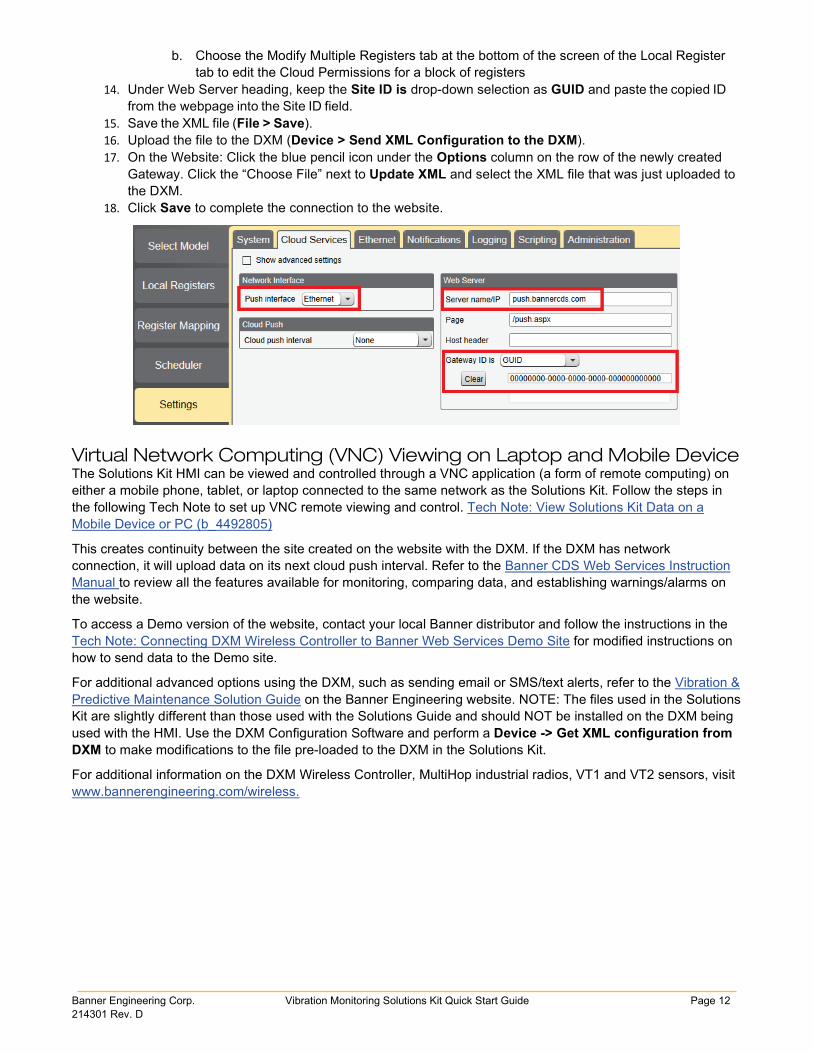
9. Within the tool, click the Settings tab on the left and then the Cloud Services tab on the top. 10. Make sure the Server name/IP is set to push.bannercds.com. 11. Select the appropriate Push interface to either Cellular or Ethernet. (To set up Ethernet, use the
Network Tab under settings. To set up cellular, refer to the Activating a Cellular Modem tech note) 12. Leave the Cloud push interval and Sample count set as they were. The DXM script controls this to
push every 5 minutes. 13. Registers are preselected to push to the cloud. Some registers can be removed if you are not using all
40 sensors. Additional registers can be added by going to the Local Registers tab on the left. The preselected READ registers are 1-200 for the raw sensor data, 201-240 for vibration failure mask info, 281-320 for sensor connection status, and 5181-5660 for baseline/threshold data. The preselected READ/WRITE registers are 321-360, which are the re-baselining registers. READ/WRITE is used so the Baseline registers can be updated from the website from a 0 to a 1 to trigger a new baseline remotely. To modify registers either:
a. Click on each register and edit the Cloud Permissions at the bottom of the screen; or
Banner Engineering Corp. Vibration Monitoring Solutions Kit Quick Start Guide Page 12 214301 Rev. D
b. Choose the Modify Multiple Registers tab at the bottom of the screen of the Local Register tab to edit the Cloud Permissions for a block of registers
14. Under Web Server heading, keep the Site ID is drop-down selection as GUID and paste the copied ID from the webpage into the Site ID field.
15. Save the XML file (File > Save). 16. Upload the file to the DXM (Device > Send XML Configuration to the DXM). 17. On the Website: Click the blue pencil icon under the Options column on the row of the newly created
Gateway. Click the “Choose File” next to Update XML and select the XML file that was just uploaded to the DXM.
18. Click Save to complete the connection to the website.
Virtual Network Computing (VNC) Viewing on Laptop and Mobile Device The Solutions Kit HMI can be viewed and controlled through a VNC application (a form of remote computing) on either a mobile phone, tablet, or laptop connected to the same network as the Solutions Kit. Follow the steps in the following Tech Note to set up VNC remote viewing and control. Tech Note: View Solutions Kit Data on a Mobile Device or PC (b_4492805)
This creates continuity between the site created on the website with the DXM. If the DXM has network connection, it will upload data on its next cloud push interval. Refer to the Banner CDS Web Services Instruction Manual to review all the features available for monitoring, comparing data, and establishing warnings/alarms on the website.
To access a Demo version of the website, contact your local Banner distributor and follow the instructions in the Tech Note: Connecting DXM Wireless Controller to Banner Web Services Demo Site for modified instructions on how to send data to the Demo site.
For additional advanced options using the DXM, such as sending email or SMS/text alerts, refer to the Vibration & Predictive Maintenance Solution Guide on the Banner Engineering website. NOTE: The files used in the Solutions Kit are slightly different than those used with the Solutions Guide and should NOT be installed on the DXM being used with the HMI. Use the DXM Configuration Software and perform a Device -> Get XML configuration from DXM to make modifications to the file pre-loaded to the DXM in the Solutions Kit.
For additional information on the DXM Wireless Controller, MultiHop industrial radios, VT1 and VT2 sensors, visit www.bannerengineering.com/wireless.

Banner Engineering Corp. Vibration Monitoring Solutions Kit Quick Start Guide Page 13 214301 Rev. D
Specifications Supply Voltage
24 V DC (±10%) (use only with a Class 2 (UL) power supply or a Limited Power Source (LPS) (CE) power supply)
Power Consumption 9 W average; 30 W maximum
Operating Conditions 0 °C to +50 °C (32 °F to +122 °F) (HMI); –20 °C to +60 °C (–4 °F to +140 °F) 90% maximum relative humidity (non-condensing)
900 MHz Compliance (1 Watt) FCC ID UE3RM1809: This device complies with FCC Part 15, Subpart C, 15.247 IC: 7044A-RM1809
2.4 GHz Compliance FCC ID UE300DX80-2400: This device complies with FCC Part 15, Subpart C, 15.247 ETSI EN 300 328: V1.8.1 (2012-04) IC: 7044A-DX8024
Radio Range 900 MHz, 1 Watt: Up to 9.6 km (6 miles) 2.4 GHz, 65 mW: Up to 3.2 km (2 miles)
Spread Spectrum Technology FHSS (Frequency Hopping Spread Spectrum)
Antenna Minimum Separation Distance 900 MHz 150 mW/250 mW: 2 m (6 ft) 900 MHz, 1 Watt: 4.57 m (15 ft) 2.4 GHz 65 mW: 0.3 m (1 ft)
Radio Transmit Power 900 MHz, 1 Watt: 30 dBm (1 W) conducted (up to 36 dBm EIRP) 2.4 GHz, 65 mW: 18 dBm (65 mW) conducted, less than or equal to 20 dBm (100 mW) EIRP
Mounting A mounting system with various mounting options is provided with this enclosure. To connect the mounting brackets, turn the enclosure such that the backside is visible. Place the mounting brackets over the octagon bosses either horizontally, diagonally, or vertically, and fasten them with the ¼”-20 x 0.25” SS, countersunk Philips drive screws provided (torque limit = 30 in. lbs.). The enclosure can be mounted vertically (on a wall) or horizontally (table top).
Certifications
(CE applies only to model SolutionsKit2-Vibemetric-MH)
(NOM applies only to the 900 MHz models)
FCC Part 15 and CAN ICES-3 (B)/NMB-3(B) This device complies with part 15 of the FCC Rules and CAN ICES-3 (B)/NMB-3(B). Operation is subject to the following two conditions:
1. This device may not cause harmful interference, and 2. This device must accept any interference received, including interference that may cause undesired operation.
This equipment has been tested and found to comply with the limits for a Class A digital device, pursuant to part 15 of the FCC Rules and CAN ICES-3 (B)/NMB-3(B). These limits are designed to provide reasonable protection against harmful interference in a residential installation. This equipment generates, uses and can radiate radio frequency energy and, if not installed and used in accordance with the instructions, may cause harmful interference to radio communications. However, there is no guarantee that interference will not occur in a particular installation. If this equipment does cause harmful interference to radio or television reception, which can be determined by turning the equipment off and on, the user is encouraged to try to correct the interference by one or more of the following measures:
• Reorient or relocate the receiving antenna. • Increase the separation between the equipment and receiver. • Connect the equipment into an outlet on a circuit different from that to which the receiver is connected. • Consult the manufacturer.
Banner Engineering Corp. Limited Warranty Banner Engineering Corp. warrants its products to be free from defects in material and workmanship for one year following the date of shipment. Banner Engineering Corp. will repair or replace, free of charge, any product of its manufacture which, at the time it is returned to the factory, is found to have been defective during the warranty period. This warranty does not cover damage or liability for misuse, abuse, or the improper application or installation of the Banner product.
THIS LIMITED WARRANTY IS EXCLUSIVE AND IN LIEU OF ALL OTHER WARRANTIES WHETHER EXPRESS OR IMPLIED (INCLUDING, WITHOUT LIMITATION, ANY WARRANTY OF MERCHANTABILITY OR FITNESS FOR A PARTICULAR PURPOSE), AND WHETHER ARISING UNDER COURSE OF PERFORMANCE, COURSE OF DEALING OR TRADE USAGE.
This Warranty is exclusive and limited to repair or, at the discretion of Banner Engineering Corp., replacement. IN NO EVENT SHALL BANNER ENGINEERING CORP. BE LIABLE TO BUYER OR ANY OTHER PERSON OR ENTITY FOR ANY EXTRA COSTS, EXPENSES, LOSSES, LOSS OF PROFITS, OR ANY INCIDENTAL, CONSEQUENTIAL OR SPECIAL DAMAGES RESULTING FROM ANY PRODUCT DEFECT OR FROM THE USE OR INABILITY TO USE THE PRODUCT, WHETHER ARISING IN CONTRACT OR WARRANTY, STATUTE, TORT, STRICT LIABILITY, NEGLIGENCE, OR OTHERWISE.
Banner Engineering Corp. reserves the right to change, modify or improve the design of the product without assuming any obligations or liabilities relating to any product previously manufactured by Banner Engineering Corp. Any misuse, abuse, or improper application or installation of this product or use of the product for personal protection applications when the product is identified as not intended for such purposes will void the product warranty. Any modifications to this product without prior express approval by Banner Engineering Corp will void the product warranties. All specifications published in this document are subject to change; Banner reserves the right to modify product specifications or update documentation at any time. Specifications and product information in English supersede that which is provided in any other language. For the most recent version of any documentation, refer to: www.bannerengineering.com.
For patent information, see www.bannerengineering.com/patents.

Banner Engineering Corp. Vibration Monitoring Solutions Kit Quick Start Guide Page 2 214301 Rev. D
Notas Adicionales Información México: La operación de este equipo está sujeta a las siguientes dos condiciones: 1) es posible que este equipo o dispositivo no cause interferencia perjudicial y 2) este equipo debe aceptar cualquier interferencia, incluyendo la que pueda causar su operación no deseada.
Banner es una marca registrada de Banner Engineering Corp. y podrán ser utilizadas de manera indistinta para referirse al fabricante. "Este equipo ha sido diseñado para operar con las antenas tipo Omnidireccional para una ganancia máxima de antena de 6 dBd y Yagi para una ganancia máxima de antena 10 dBd que en seguida se enlistan. También se incluyen aquellas con aprobación ATEX tipo Omnidireccional siempre que no excedan una ganancia máxima de antena de 6dBd. El uso con este equipo de antenas no incluidas en esta lista o que tengan una ganancia mayor que 6 dBd en tipo omnidireccional y 10 dBd en tipo Yagi, quedan prohibidas. La impedancia requerida de la antena es de 50 ohms."
Antenas SMA Modelo Antena, Omni 902-928 MHz, 2 dBd, junta de caucho, RP-SMA Macho BWA-9O2-C Antena, Omni 902-928 MHz, 5 dBd, junta de caucho, RP-SMA Macho BWA-9O5-C
Antenas Tipo-N Modelo Antena, Omni 902-928 MHz, 6 dBd, fibra de vidrio, 1800mm, N Hembra BWA-9O6-A Antena, Yagi, 900 MHz, 10 dBd, N Hembra BWA-9Y10-A
Mexican Importer Banner Engineering de Mèxico, S. de R.L. de C.V. David Alfaro Siqueiros 103 Piso 2 Valle oriente San Pedro Garza Garcia Nuevo Leòn, C. P. 66269 81 8363.2714