vibrational characteristics of soil deposits with...
TRANSCRIPT
INTERNATIONAL JOURNAL FOR NUMERICAL AND ANALYTICAL METHODS IN GEOMECHANICS. VOL. 6. 1-20 (1982)
VIBRATIONAL CHARACTERISTICS OF SOIL DEPOSITS WITH VARIABLE WAVE VELOCITY
GEORGE GAZETAS~ Department of Civil Engineering, Rensselaer Polytechnic Insiiiuie, Troy, N. Y. 12181, U.S.A.
SUMMARY The paper studies certain dynamic characteristics of soil deposits with wave velocities increasing with depth according to (l+pz)'", where m = 1, 2/3, 1/2, 1/4 and 0. Analytical solutions are presented for the fundamental periods, mode shapes and amplification functions due to vertically propagating shear waves and the effects of type (m) and rate ( p ) of heterogeneity are systematically investigated. Then analytical- numerical techniques are used to study the attenuation with depth in a deposit of the vertical and horizontal displacements due to travelling of Rayleigh waves. Differences attributed to different heterogeneities are discussed in connection with the machine isolation problem and the steady-state vibration technique for soil exploration. Finally, the dependence on soil heterogeneity of the time-distance response curves, obtained during seismic refraction surveys, is graphically illustrated.
INTRODUCTION
The dynamic characteristics of soil deposits are of interest to civil engineers involved in the design or isolation of machine foundations, the protection of structures against earthquakes, the safety of offshore platforms and caissons during wave-storms, etc. For example, resonance phenomena during foundation vibrations have been observed to occur at frequencies closely related to the natural frequencies of the underlying soil deposit.'-3 Also, to effectively isolate structures and machine foundations from ground transmitted vibrations (passive or active isolation) trench barriers are constructed. Determination of their location and depth depends on how the energy from Rayleigh or Love waves varies with depth from the surface and with distance from the source, in the particular soil Furthermore, surface acceleragrams recorded during earthquakes reflect to some degree the dynamic characteristics of the near- surface soil layers at the recording site. Recently proposed or established seismic codes in many countries with high earthquake activity (e.g. Japan, Chile, Mexico, Turkey, U.S.A.) specify design spectra which depend on the fundamental period of the soil deposit that underlies the structure.
In recent years, certain vibrational characteristics of soil deposits and their importance in specific areas of soil dynamics have been extensively studied. In particular, semiempirical, analytical and numerical methods have been developed to determine natural frequencies and amplification functions of soil deposits excited by S - ~ a v e s . ~ ' ~ Vibrations caused by Rayleigh or Love waves have also received some attention.'" Despite all the progress made, simple analytical solutions have always been in demand since they allow parametric studies to be easily performed and since they can be incorporated in building codes. Thus, in 1976, Dobry et u I . , ~ motivated by the then forthcoming new UBC code, offered analytical solutions for the
t Professor.
0363-9061/82/010001-20$02.00 @ 1982 by John Wiley & Sons, Ltd.
Received 15 December 1979 Revised 22 August 1980
2 G . GAZETAS
fundamental periods of vibration of certain heterogeneous deposits due to vertically propagat- ing S-waves.
This paper, an outcome of a broader effort to evaluate the importance of heterogeneities in soil dynamics, describes the study of four realistic types of heterogeneous deposits with wave velocities increasing with depth in proportion to (1 + p ~ ) ~ , where p is a positive constant and m is equal to 1,2 /3 , 1/2, and 1/4 for each soil category, respectively. Analytical and analytical- numerical methods, appropriate for estimating the dynamic behaviour of such deposits due to vertical shear (S) or due to Rayleigh (R) waves, are presented. Comparative studies demon- strate the influence of the type (m) and of the rate ( p ) of heterogeneity on the fundamental period and the fundamental mode shape of the deposit, the amplification of vertically propagat- ing S-waves and the dispersion and attenuation with depth of Rayleigh waves. The importance of these effects in specific soil-dynamics problems is emphasized throughout the discussion. Finally, the dependence on soil heterogeneity of the time-distance response curves from seismic refraction surveys is illustrated.
HORIZONTAL FREE VIBRATIONS-NATURAL FREQUENCIES AND MODE SHAPES
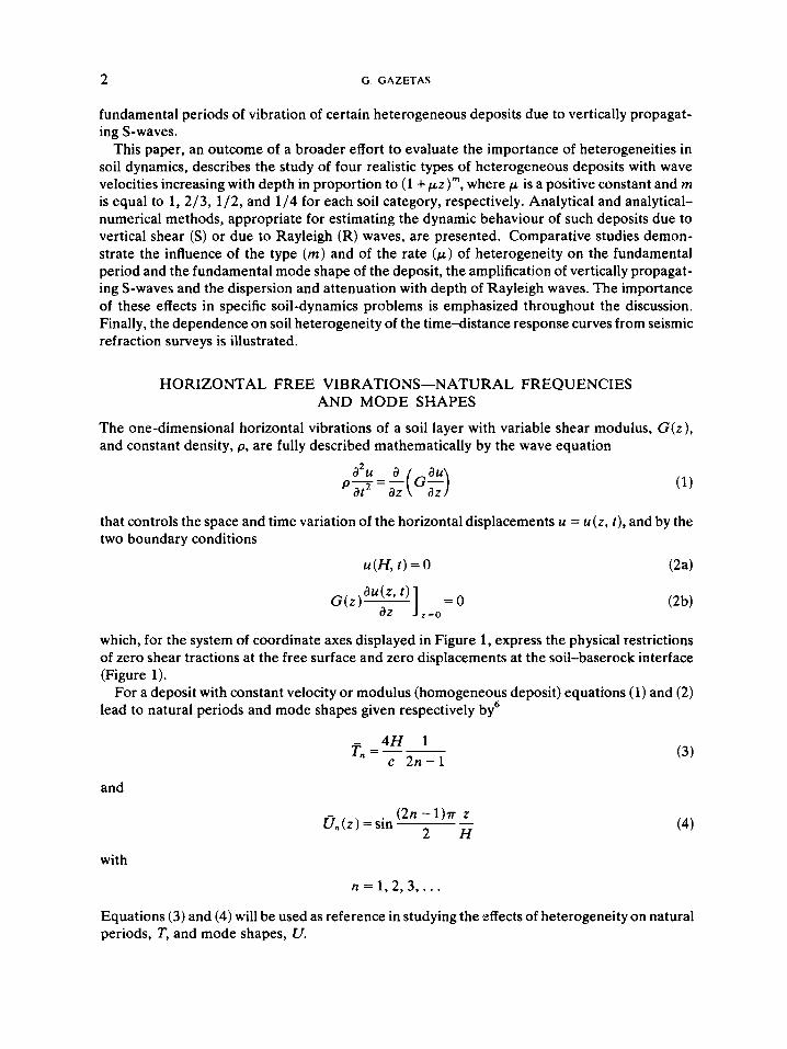
The one-dimensional horizontal vibrations of a soil layer with variable shear modulus, G ( z ) , and constant density, p, are fully described mathematically by the wave equation
that controls the space and time variation of the horizontal displacements u = u(z , t), and by the two boundary conditions
u(H, t) = 0 (2a)
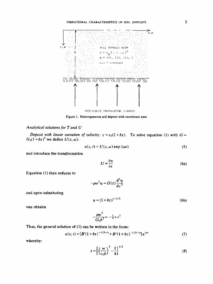
which, for the system of coordinate axes displayed in Figure 1, express the physical restrictions of zero shear tractions at the free surface and zero displacements at the soil-baserock interface (Figure 1).
For a deposit with constant velocity or modulus (homogeneous deposit) equations (1) and (2) lead to natural periods and mode shapes given respectively by6
- 4H 1 T,, =-
c 2 n - 1
and
(2n - l ) ~ z 2 H
- On(z) =sin
(3)
(4)
with
n = 1 , 2 , 3 , . . Equations (3) and (4) will be used as reference in studying the effects of heterogeneity on natural periods, T, and mode shapes, U.
VIBRATIONAL CHARACTERISTICS OF SOIL DEPOSITS 3
V E R T i CAI.1.Y I'ROPA(:ATIN(; S-IJAVI:S
Figure 1 . Heterogeneous soil deposit with coordinate axes
Analytical solutions for T and U
Go(l + 6 ~ ) ~ we define U ( z , w ) : Deposit with linear variation of velocity: c = co( l+ bz ) . To solve equation (1) with G =
( 5 ) u(z , t ) = U ( z , w ) exp (iwt)
and introduce the transformation
Equation (1) then reduces to
and upon substituting
one obtains
Thus, the general
whereby:
77 = (1 + bz)r+1'2
1 2 --= w2 - a + r Gob'
olution f (1) can be written in the form:
u(z , t ) = [ ~ ' ( 1 + 6 z ) ~ ' ~ " ' + B " ( 1 + ~ ~ ) ~ ' ' 2 ~ i " ] i " '
4 G . GAZETAS
in which co is the shear wave velocity at the surface. Substitution of (7) into the boundary conditions (equation (2)) yields the following ‘characteristic’ equation
(9) S,, In (1 + b H ) + arctan (2S,,) = n r n = 1 , 2 , 3 , . . .
from which the eigenvalues S,, can be numerically recovered, for example using the Newton- Raphson method.” Calling 6’ = bH the dimensionless rate of heterogeneity, allows the natural periods of the deposit in horizontal shear vibrations to be expressed as
4 H n T,, =- n = 1 , 2 , 3 , . .
co i {4S2,+1}
The eigenfunctions (modal shapes) are then given in a dimensionless form by
where r’ = z / H
The general solution to the wave equation (1) for a constant density unbounded medium having velocity c = co(l + /z ) * /~ , has been published by Schreyer.” For a deposit resting on a rough base (Figure 1) the solution can be written as
u ( z , ~ ) = ( I + & - ” ~ ( ~ ‘ e x p [ i s ( [ l + ~ ~ ] ’ ’ ~ - l ) ] + ~ ~ ~ e x p [ - i s ( [ + i z - ] ’ ’ ~ - 1 ) ] ) (12)
Deposit with oelocity increasing according to : c = co( I i lz)?
in which
i= IH
z‘= z / H
Compliance with the boundary conditions (equation (2)) leads to the ‘characteristic’ relation:
S,,[(1+~)‘/3-1]+arctan(S,,)=nr n = 1 , 2 , 3 , . . . . (14)
The natural periods of the deposit are obtained from
4 H 3 n T , = - - co 21sn
after S,, have been numerically computed from (14), and the corresponding mode shapes are
u,, = (1 + sin (s,,[(I + - (1 + i)1/3]) (16)
Natural periods and mode Deposit with velocity increasing according to c = co(l +fz)’/’. shapes for such a profile have been obtained by Arnbraseys” and by Dobry et ai.:’
4H nk CO (1-k2)S, ,
T =-
U,, =Jo(kS,,[l +ff]’/2)Yo(S,,)- Yo(kS,,[l +fr’]’/2)Jo(S,,)
n = 1 , 2 , 3 , . . . (18)
VIBRATIONAL CHARACTERISTICS OF SOIL DEPOSITS 5
in which: f= fH; 2 = z /H; k = (1 +f)-ll2; and Sn are the solutions of the 'characteristic' equation, CJ, (2 = 1) = 0.'
Toki and Cherry13 have solved the wave equation for a class of deposits with modulus increasing in proportion to ( z +d)'/", n = 2 ,3 ,4 , . . . , and constant density, d . For the particular case c = c ~ ( l +gz) ' l4 their general solution simplifies to
Deposit with velocity increasing according to: c = co(l +gz)ll4.
U ( z , w ) = (1 + @)1'4[E'J1/3(s(1 + E"Y1/3(S(l+ di)"")] (19)
in which: kind, respectively. The 'characteristic' equation corresponding to (19) is
= gH; J1/3( * ) and Y1/3( - ) are the Bessel functions of order 1/3, first and second
in which: q = (1 +g)3/4. The solution of this transcendental equation with one of the standard numerical methods" is
not recommended since it appears to be quite tedious to check their convergence. Instead, the computer algorithm ZEROIN developed at the Mathematical Center in Amsterdam, was implemented to solve equation (20). ZEROIN combines the bisection and the secant method and guarantees ~0nvergence. l~
Natural periods and mode shapes are then obtained from (21) and (22), respectively:
Presentation of results-effects of type and rate of heterogeneity
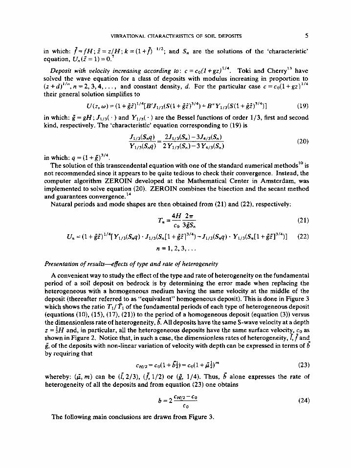
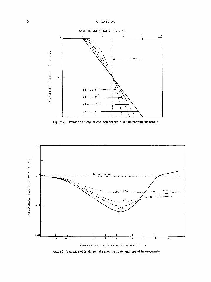
A convenient way to study the effect of the type and rate of heterogeneity on the fundamental period of a soil deposit on bedrock is by determining the error made when replacing the heterogeneous with a homogeneous medium having the same velocity at the middle of the deposit (thereafter referred to as "equivalent" homogeneous deposit). This is done in Figure 3 which shows the ratio Tl/Fl of the fundamental periods of each type of heterogeneous deposit (equations (lo), (15), (17), (21)) to the period of a homogeneous deposit (equation (3)) versus the dimensionless rate of heterogeneity, 6. All deposits have the same S-wave velocity at a depth z = and, in particular, all the heterogeneous deposits have the same surface velocity, co as shown in Figure 2. Notice that, in such a case, the dimensionless rates of heterogeneity, [ fand g, of the deposits with non-linear variation of velocity with depth can be expressed in terms of 6 by requiring that
cH/2 = cO(1 + g$) = cO(1 + 4;)" (23)
whereby: (4, rn) can be ([ 2/3), (1 1/2) or (g, 1/4). Thus, 6 alone expresses the rate of heterogeneity of all the deposits and from equation (23) one obtains
(24) c H / 2 - CO b=2-
co
The following main conclusions are drawn from Figure 3.
6
-
G. GAZETAS
WAVE VELOCITY RATIO : c / Co
1 2 3 4 5 I I I
1.
0
0.5
1
y.., :
Figure 2. Definition of ‘equivalent’ homogeneous and heterogeneous profiles
0.9
0.81 I I 1 1 I 1 I I I 0.05 0.1 0 . 5 1 L 5 10 20 50
DIMENSIONLESS M T E OF HETEROGENEITY : b
Figure 3. Variation of fundamental period with rate and type of heterogeneity

VIBRATIONAL CHARACIERISTICS OF SOIL DEPOSITS 7
(i) The heterogeneous layers experience shorter fundamental periods and thus behave as if they are stiffer than the ‘equivalent’ homogeneous deposit, despite the larger, or at least equal, average velocity of the latter (Figure 2). The phenomenon is attributed to the sharper decrease of modal amplitudes with depth in the homogeneous strata, as illustrated in Figure 5 . This in essence reduces the ‘effective’ thickness Her of these deposits (i.e. the thickness of the soil where vibration amplitudes are not negligibly small) and, thus, compensates for their smaller average velocity. t
(ii) For a given value of 6’ (not larger than 7), the apparent stiffening of the deposit increases with the power, m, that describes the variation of velocity with depth, i.e. c = co(l + @ z ) ~ . It is largest for m = 1 (linear variation) and smallest for m = 1/4 (fourth-root variation). That is, the closer to uniform the distribution of velocity with depth in a particular layer is, the larger the fundamental period of this layer becomes.
(iii) With increasing 6, the heterogeneous layers become progressively stiffer in comparison with the equivalent homogeneous layer. However, it comes as a surprise that for a particular value of 6’, around 3, the relative stiffening effect reaches its peak; in other words, Tl/Tl has a minimum at approximately 6’= 3 for all types of heterogeneity ( m = 1,2/3, 1/2, 1/4). The corresponding valley of the TI/TI vs. 6’ curve is most pronounced when m = 1 (linear variation of velocity) while it is almost imperceptible when m = 1/4. The phenomenon is reminiscent of the ‘optimum’ coupling that Schreyer” observed while studying the one-dimensional elastic waves produced in a heterogeneous ( m = 2/3) halfspace by an exponentially decaying compressive pulse uniformly applied on the surface: for every value of loading decay rate, there exists a particular value of the rate of heterogeneity (I) for which the compressive impulse induced in the medium attains a maximum value.
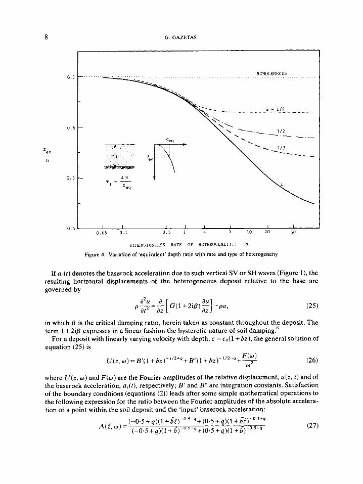
An alternate way to present the fundamental periods of the variable velocity deposits is by plotting the dependence of the “equivalent” depth, zeq, on the rate of heterogeneity, 6’. The ‘equivalent’ depth zeq is defined (after Dobry et d7) as the depth at which the wave velocity c,, of the soil is such that the first natural period of the deposit is given by T = 4H/ceq. Figure 4 depicts zeq (normalized with respect to layer thickness) as a function of 6’ for all four types of heterogeneity studied. (The definition of ‘equivalent’ depth is also graphically explained in the figure.) The reader may consult Reference 7 for additional discussion of the zeq concept.
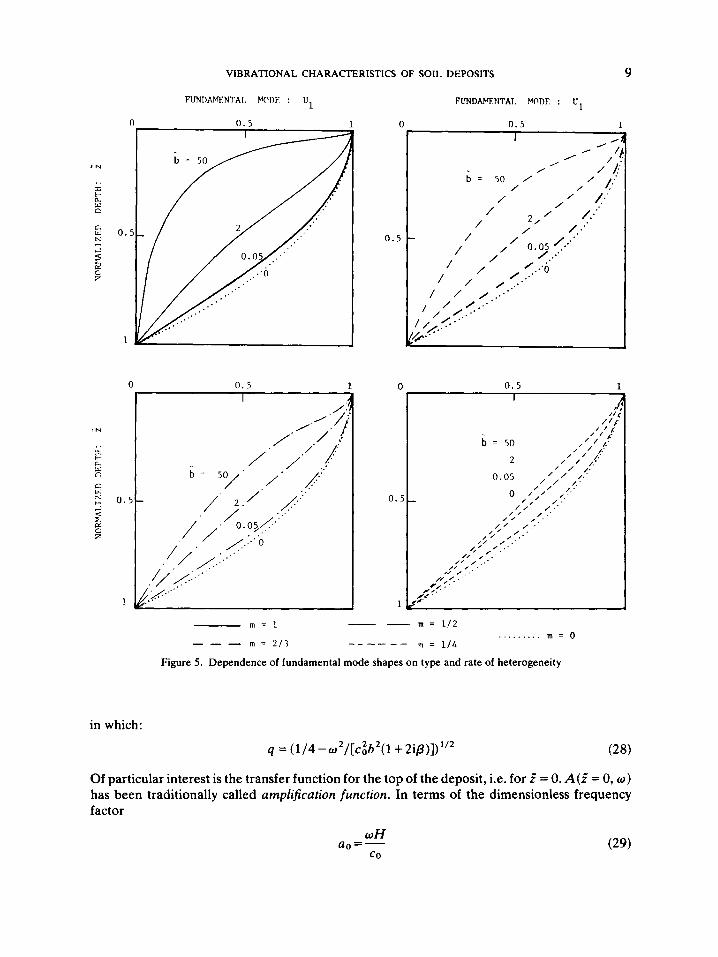
Finally Figure 5 demonstrates the sensitivity of the first mode shapes on the type ( m ) and the rate ( b ) of heterogeneity of a deposit. Notice in particular the very sharp increase of modal amplitudes near the surface of the layers with m = 1 and m = 2 / 3 for high rates 6: The dependence of the higher modal shapes on m and 6’, being of similar nature, is not discussed here.
1 -DIMENSIONAL FORCED VIBRATIONS: SOIL AMPLIFICATION OF EARTHQUAKES
Current procedures which are commonly used to study the effect of local soil conditions on the amplitude and frequency content of near surface motions are based on the assumption of vertically propagating S - ~ a v e s . ~ ” This assumption has been employed because, within the present state-of-knowledge, it is practically impossible to accurately predict for a potential earthquake the nature of incoming waves, their angle of incidence and their relative amplitudes. Moreover, it is known that close to the epicentre, continuous transmission of upward propagat- ing S-waves through increasingly soft layers gradually changes their angle of incidence to near vertical.’
T Remember that T is proportional to He<. cav.
8 G. GAZETAS
0.7
0.6
0 . 5
0 .4
LjIfah’SIONLESS RATE OF HETEROGENEITY: b
Figure 4. Variation of ‘equivalent’ depth ratio with rate and type of heterogeneity
If a,(r) denotes the baserock acceleration due to such vertical SV or SH waves (Figure l), the resulting horizontal displacements of the heterogeneous deposit relative to the base are governed by
in which p is the critical damping ratio, herein taken as constant throughout the deposit. The term 1 + 2ip expresses in a linear fashion the hysteretic nature of soil damping.6
For a deposit with linearly varying velocity with depth, c = co( 1 + bz) , the general solution of equation (25) is
where U ( z , o) and F ( o ) are the Fourier amplitudes of the relative displacement, u(z , t ) and of the baserock acceleration, df) , respectively; B’ and B“ are integration constants. Satisfaction of the boundary conditions (equations (2)) leads after some simple mathematical operations to the following expression for the ratio between the Fourier amplitudes of the absolute accelera- tion of a point within the soil deposit and the ‘input’ baserock acceleration:
VIBRATIONAL CHARACTERISTICS OF SOIL DEPOSITS 9
(
0 . 5
FUNDAYENTAT. MODE : U,
0 .5 1
0 n . 5 1 0 0.5 1
0. f
1
m = 112
m = 114
-- - m = l
- - - m = 2 1 7 ......... m = O -_ - - - -
Figure 5 . Dependence of fundamental mode shapes on type and rate of heterogeneity
in which:
q = (1 /4-w2/[c~b2(1 +2i/3)])”z
Of particular interest is the transfer function for the top of the deposit, i.e. for r‘ = 0. A(? = 0, w ) has been traditionally called amplification function. In terms of the dimensionless frequency factor
UH uo=-
co
10 G. GAZETAS
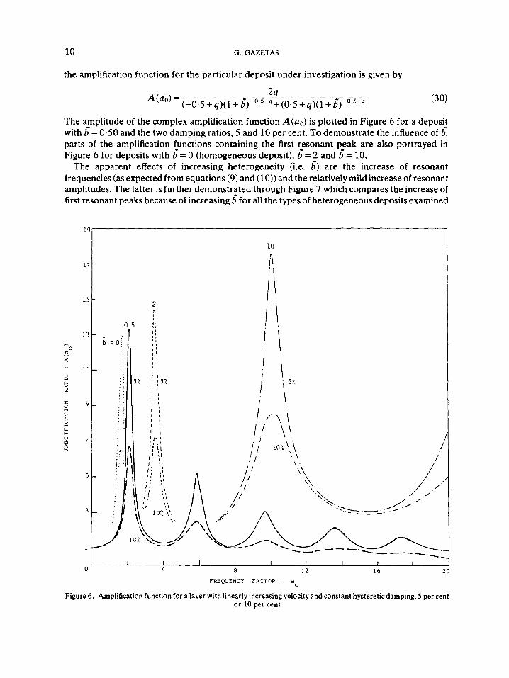
the amplification function for the particular deposit under investigation is given by
2q A(ao)= ( - 0 . 5 + q ) ( l +d)-0'5-q+(05+q)(l+&0'5+q
The amplitude of the complex amplification function A(a0) is plotted in Figure 6 for a deposit with 6= 0.50 and the two damping ratios, 5 and 10 per cent. To demonstrate the influence of 6, parts of the amplification functions containing the first resonant peak are also portrayed in Figure 6 for deposits with 6' = 0 (homogeneous deposit), d = 2 and 6 = 10.
The apparent effects of increasing heterogeneity (i.e. d) are the increase of resonant frequencies (as expected from equations (9) and (10)) and the relatively mild increase of resonant amplitudes. The latter is further demonstrated through Figure 7 which compares the increase of first resonant peaks because of increasing d for all the types of heterogeneous deposits examined
I S
17
15
1 3 - 0
0
a: '' 11
- 2 d
2 k E 7
2 9
<
c
4
5
3
1
0
- 2 b = O l i
. . . . . . , . . . , . . . . . . .
. (
. .'. _ . . . . . . . .. . ._ . . .
. ,
/
I I I I I 1 I I I
4 8 1 2 1 6 20 FREQUENCY FACTOR : a
Figure 6. Amplification function for a layer with linearly increasing velocity and constant hysteretic damping, 5 per cent or 10 per cent
VIBRATIONAL CHARACTERISTICS OF SOIL DEPOSITS 11
0.1 0 . 5 1 2 10
Dl!4E~SIONI.I:S.' RA?E OF !!ETEROGFNEITY: b
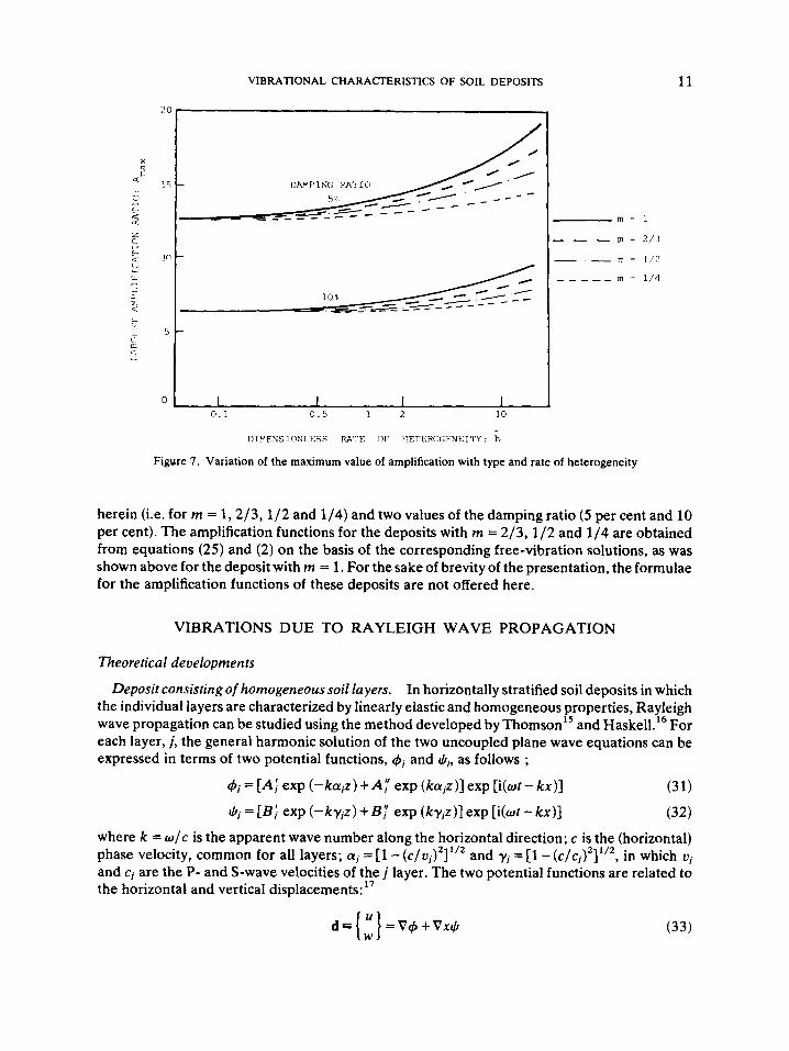
Figure 7 . Variation of the maximum value of amplification with type and rate of heterogeneity
herein (i.e. for rn = 1,2 /3 ,1 /2 and 1/4) and two values of the damping ratio (5 per cent and 10 per cent). The amplification functions for the deposits with in = 2/3, 1/2 and 1/4 are obtained from equations (25) and (2) on the basis of the corresponding free-vibration solutions, as was shown above for the deposit with rn = 1. For the sake of brevity of the presentation, the formulae for the amplification functions of these deposits are not offered here.
VIBRATIONS DUE TO RAYLEIGH WAVE PROPAGATION
Theoretical developments
In horizontally stratified soil deposits in which the individual layers are characterized by linearly elastic and homogeneous properties, Rayleigh wave propagation can be studied using the method developed by T h o m ~ o n ' ~ and Haske1l.l6 For each layer, j , the general harmonic solution of the two uncoupled plane wave equations can be expressed in terms of two potential functions, q5j and q?j, as follows ;
4j=[Aj exp(-kajz)+A; exp(kajz)]exp[i(ot-kx)] (31)
(Li = [Bj exp (-kyjz) +By exp (kyjz)] exp [i(ot - kx)] (32) where k = w / c is the apparent wave number along the horizontal direction; c is the (horizontal) phase velocity, common for all layers; ai = [l - ( c / v j ) 3 and yj = [l - (C/C~)~]~ '* , in which v j and c j are the P- and S-wave velocities of the j layer. The two potential functions are related to the horizontal and vertical displacements:"
Deposit consisting of homogeneous soil layers.
2 1/2
d = [ E] = V 4 +Vxq? (33)
12 G. GAZETAS
The boundary conditions of the problem are:8 (i) zero normal and shear stresses at the free surface; (ii) continuity of displacements (u, w ) and stresses (wz, T ~ * ) at all layer-interfaces; and (iii) no upward propagating waves in the baserock. Imposing these requirements on displace- ments obtained from (33) and on stresses obtained from the stress-strain relationships of linear elasticity yields a ‘characteristic’ equation (‘dispersion’ relationship) of the form
f(w9 c ) = 0 (34)
from which the phase velocities c are numerically determined for each value of the frequency w. To each particular c there corresponds an eigenvector or Rayleigh-wave mode d(z ; w, c). Each component (horizontal or vertical) of a particular mode is normalized herein to a unit surface amplitude, that is, so as to represent the attenuation with depth of the corresponding component of modal displacement; i.e.
express the attenuation of horizontal and vertical displacements, respectively, in the multi- layered medium considered. Since the higher Rayleigh wave modes decay extremely fast in the frequency range of interest to designers of machine foundations or to earthquake engineer^,^ only the fundamental mode (defined as the mode with the smallest c) is examined in this paper.
To extend the previous analysis to a soil deposit consisting of heterogeneous layers, one must be able to analytically express the solution of the governing plane wave equations for each heterogeneous layer j , as is done with equations (31), (32) and (33) for a homogeneous layer. For an arbitrary variation of S-wave velocity with depth this task is formidable, because uncoupling the two equations of motion is possible only in very rare cases.’* One of these cases is when the velocity varies linearly with depth. GuptaIg has presented a method of uncoupling the governing equations for such a medium in terms of pseudo- dilatational and pseudo-distortional wave potentials, 4 and $, defined by
Heterogeneous soil deposits.
d = {GV(G-’4) + G-’V x (G $)} exp ( i d ) (36)
The resulting two uncoupled wave equations are:
vz4 + [h,(2)324 = 0 (37)
V2$ + [hs(z)I2$ = 0 (38)
h p j ( 2 ) = w/o~(z ) ; h,j = o/c~(z) (39)
where the wave numbers, h, and h,, are given for each layer, j , by
where ui, ci are the P- and S-wave velocities, that both vary linearly with depth [e.g. c j = coj(l + bz)] . Equations (37) and (38) look like the classical wave equations for P- and S-waves. However, because of the way the two potentials are related to displacements (equation (36)), such P-waves are not purely irrotational, nor are S-waves purely equivoluminal. Nevertheless, equations (37)-(38) can be solved analytically after some lengthy operations that can be found elsewhere.” The solution is written in terms of modified Bessel functions Z and K of the first and second kind, respectively:
d j = (1 +bjz)1’2[A~lpi(kaj/bj)+A~Kp,(kaj/bj)] exp [i(wt - k x ) ] (40)
(41) $j = (1 +bjz)”2[81~,,(kaj/bi) + ~ ; ~ ~ , ( k a ~ / b ~ ) ] exp [i(wt - k x ) ]
VIBRATIONAL CHARACTERISTICS OF SOIL DEPOSITS 13
where: k = w / c is the apparent wave number along the x direction; a, = 1 + biz ; and the orders pi and 4j of the Bessel functions are:
Notice that in general pi and qj are complex numbers, if the wave velocities in (42) are multiplied by (1 + 2ip)’/’, to account for internal hystereticdamping in the soil. It can easily be shown that, for realistic values of p, the real parts of pi, 4j satisfy the inequality
that is the necessary and sufficient condition for existence of the modified Bessel functions (see Watson” ).
The analysis proceeds from equations (40), (41), (42) in exactly the same way as the analysis for homogeneous-multilayered deposits proceeds from equations (31), (32), (33).
For the other three types of heterogeneous deposits (i.e. with m = 2/3, 1 /2 and 1/4) closed-form solutions of the governing wave equations are not possible to obtain. Rayleigh wave propagation in these deposits is studied by using the method described for homogeneous- multilayered media. The deposits are divided in 20 layers having a minimum thickness equal to 0 .03H near the free surface and a maximum equal to 0.10H near the baserock. The velocity of the corresponding heterogeneous deposit at the middle of each layer is taken as the constant velocity of the layer.
Characteristic results-effect of heterogeneity
Results are presented in this section only for one, characteristic value of the dimensionless rate of heterogeneity: b’= 3. The baserock velocity is taken as 8c0, where co is the surface velocity common to all heterogeneous deposits. No hysteretic damping is considered in the soil, since phase velocities and modal shapes that are of interest here are relatively unaffected by small amounts of damping.
Figure 8 compares the ‘dispersion’ relationship of the four heterogeneous and the ‘equivalent’ homogeneous deposits. As expected, the phase velocity c tends to the Rayleigh wave velocity of the baserock at very low frequencies (high wavelengths) and the dispersion curves of all the deposits coincide. Differences show up at frequencies higher than 2 cps, since for very short wave-lengths c is controlled by the S-wave velocity of the near-surface soil, which is different in the five deposits under consideration. Notice that in the homogeneous deposit c is independent of frequency, beyond approximately 3 cps. This implies that the existence of baserock has little or no influence on high-frequency R-waves propagating through a relatively deep stratum. For instance, in the 100-m-thick deposit examined, the Rayleigh wave-length corresponding to f = 5 cps is A R = c/f i 250/5 = 50 m, i.e. only one-half of the layer thickness H; thus, the wave-induced vibrations will be limited to a depth less than H, as is evident from the discussion that follows.
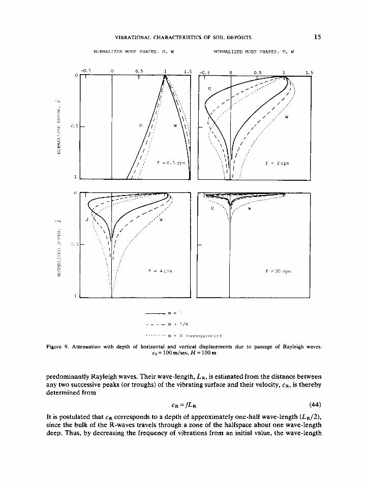
Of greater importance is the attenuation with depth of the vertical and horizontal displace- ments of the fundamental mode of a R-wave with frequency w = 27rf. Figure 9 illustrates the strong dependence of U ( z ) and W ( z ) on frequency and type of heterogeneity. For the sake of simplicity of the figure, only the curves of the heterogeneous deposits with m = 1 and rn = 1/4 are portrayed, since the m = 2/3 and m = 1/2 curves fall in between those two.
Two conclusions are drawn from Figure 9.

14 G . GAZETAS
...
m = l
_ _ _ _ m = 2 / 3
m 7 1 / 2
- _ _ - _ m - 1 / 4
-.-
. . . . . . . . . . . m = 0 (honoqeneous)
rLT-1
..................................................
rLT-1
....................................................... c *I &- -$
- - - - - - - - - - - - - - - _ _ ‘a-- - - - - - - - - -
1 I I I I I I I I 1 1 n 1 0 2’)
r v n i I A( %, c I
Figure 8. Comparison of the Rayleigh wave dispersion curves ( 6 = 3 and b’= 0). co= 100 rn/sec, H = 100 m
(i) As the frequency of vibration increases, the attenuation of both horizontal and vertical displacements with depth becomes sharper. This is hardly surprising in view of the decrease of the wave-length, in all the deposits considered.
(ii) The fastest decay of motion with depth is observed in the deposit with linearly increasing velocity with depth (rn = l), and the slowest in the homogeneous deposit. With increasing frequency, the discrepancies of the two extreme media become more pronounced, whereas the attenuation curves of all the heterogeneous strata practically coincide for very high frequencies. This suggests that surface wave velocity is the controlling parameter in this frequency range and the ‘equivalent’ homogeneous deposit should have the same top rather than the same average velocity with the inhomogeneous deposits.
The above conclusions are of practical significance in the design of wave barriers to isolate structures and machine foundations from ground-transmitted vibrations. For active isolation with trenches that fully surround the source of vibration, Richart er d4 on the basis of model tests recommend that the ratio of trench depth to wave-length of the R-wave (D/L, ) should be about 0.6. It is clear from Figure 9 that their recommendation would lead to quite different trench depths, depending on the assumed variation of S-wave velocity with depth and the range of frequencies that are of interest. At high frequencies a good estimate of the near-surface velocity is all that is needed for a proper design of the trench; whereas at very low frequencies it is more important to estimate the average velocity of the profile. However, knowledge of the variation of the velocity with depth is necessary at the intermediate frequency range.
The steady-state vibration technique for subsurface soil exploration4 is based on the fact that the waves generated by a vertically oscillating circular footing at the surface of a halfspace are
VIBRATIONAL CHARACTERISTICS OF SOIL DEPOSITS
NOR\IAI.IZED MODE SllAFES: l J , W NORMALIZED MODE SHAPES: [ I , W
-0.5 0 I
0.5 1 1.5
'.. . u '..
15
- m = 1
in = 1 / 4 _ _ _ _ rn = 0 ( ' i i ~ , ~ ( j ~ ~ , , ~ ~ [ , u ' , ) . . . . . . . .
Figure 9. Attenuation with depth of horizontal and vertical displacements due to passage of Rayleigh waves. c,, = 100 m/sec, H = 100 m
predominantly Rayleigh waves. Their wave-length, LR, is estimated from the distance between any two successive peaks (or troughs) of the vibrating surface and their velocity, cR, is thereby determined from
C R = f L R (44)
It is postulated that cR corresponds to a depth of approximately one-half wave-length ( L R / ~ ) , since the bulk of the R-waves travels through a zone of the halfspace about one wave-length deep. Thus, by decreasing the frequency of vibrations from an initial value, the wave-length
16 G. GAZETAS
increases and the R-wave motion affects soil at a greater depth; conversely, wave characteristics are also influenced by the soil properties at these greater depths. Therefore, different wave- lengths effectively 'sample' material extending to different depths and, thereby, having different average properties. According to the widely accepted steady-state vibration technique, it is possible to determine the variation of velocity with depth in a soil deposit by assigning the cR measured at each frequency to a depth LR/2.
The validity of the method is tested here for the four types of heterogeneity discussed above. Considering sufficiently high frequencies to minimize the influence of the baserock, one can determine the wave-length, L R , of the R-waves by means of Figure 8 and equation (44). For each deposit, the depth d at which the S-wave velocity is equal to the particular cR, is obtained by solving:
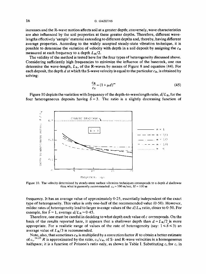
Figure 10 depicts the variation with frequency of the depth-to-wavelength ratio, d /LR, for the four heterogeneous deposits having ;= 3 . The ratio is a slightly decreasing function of
FRE~)I 'T:NC'Y : <:I,,;
Figure 10. The velocity determined by steady-state surface vibration techniques corresponds to a depth d shallower than what is presently recommended. c,, = 100 m/sec, H = 100 m
frequency. It has an average value of approximately 0-25, essentially independent of the exact type of heterogeneity. This value is only one-half of the recommended value (0-50). However, milder rates of heterogeneity lead to larger average values of the d / L R ratio, closer to 0.50. For example, for 6 = 1, average d / L R = 0.45.
Therefore, one must be careful in deciding to what depth each value of c corresponds. On the basis of the results reported here, it appears that a shallower depth than d = LR/2 is more appropriate. For a realistic range of values of the rate of heterogeneity (say: 1 S 3 ) an average value of LR/3 is recommended.
Note, also, that sometimes cR is multiplied by a correction factor R to obtain a better estimate of cs.24.25 R is approximated by the ratio, cS/cR, of S- and R-wave velocities in a homogeneous halfspace; it is a function of Poisson's ratio only, as shown in Table I. Substituting cs for c, in

VIBRATIONAL CHARACTERISTICS OF SOIL DEPOSITS 17
Table I. R as function of v
V 0.25 0.33 0.40 0.50 R 1.088 1.073 1.060 1.047
equation (45) leads to depth-over-wavelength ratios, d /LR, that are slightly increasing functions of frequency. The average d/LR values, over the frequency range examined, range from approximately 0.45, for b’= 3, to 0.70, for 6’= 1. Thus, a value of d/LR = 0.5, as is used presently in practice, seems reasonable in this case.
SEISMIC REFRACTION SURVEY
The seismic refraction survey is well suited for soil exploration of deposits consisting of layers whose stiffness increases with their distance from the surface. The theory on which the method is based is well known to the For horizontal, homogeneous layers the travel time-vs.-distance (f-x) curve consists of segments of straight lines. Each line corresponds to a particular layer and its slope, df/dx, is the inverse of the wave velocity in the layer. The wave rays also consist of segments of straight lines, as the first arriving signals travel either directly from the source to the receiver or after refraction at a particular layer-interface.
In a medium with variable velocity Snell’s law of refraction, sinO(z)/c(z) = constant, requires that the wave rays have a curvature equal to
dc pdz
in which p = sin Oo/co is the ray parameter. For a linear variation of velocity, c = co(l + bz), this leads to circular ray-paths, as schematically shown in Figure 11. For the other types of heterogeneous deposits considered in this paper, the shape of the ray-paths depends on the ray parameter p, i.e. on the angle Oo of immergence of the ray into the ground.
r . I N f ; OF C E N T E R S
1
VEI.OC TTY PROF 1 I . E
I / /
\ \ / \ /
/ , \ I . . , . /
. / - - _ - - -
Figure 1 I . Illustration of the seismic refraction method. Deposit with linearly increasing velocity on elastic rock
18 G. GAZETAS
The travel time-vs.-distance response curves for the directly arriving waves can be computed through the parameter p from the integrals26
dz
pc dz 2 2 1/2
[ I - P c 1 (47)
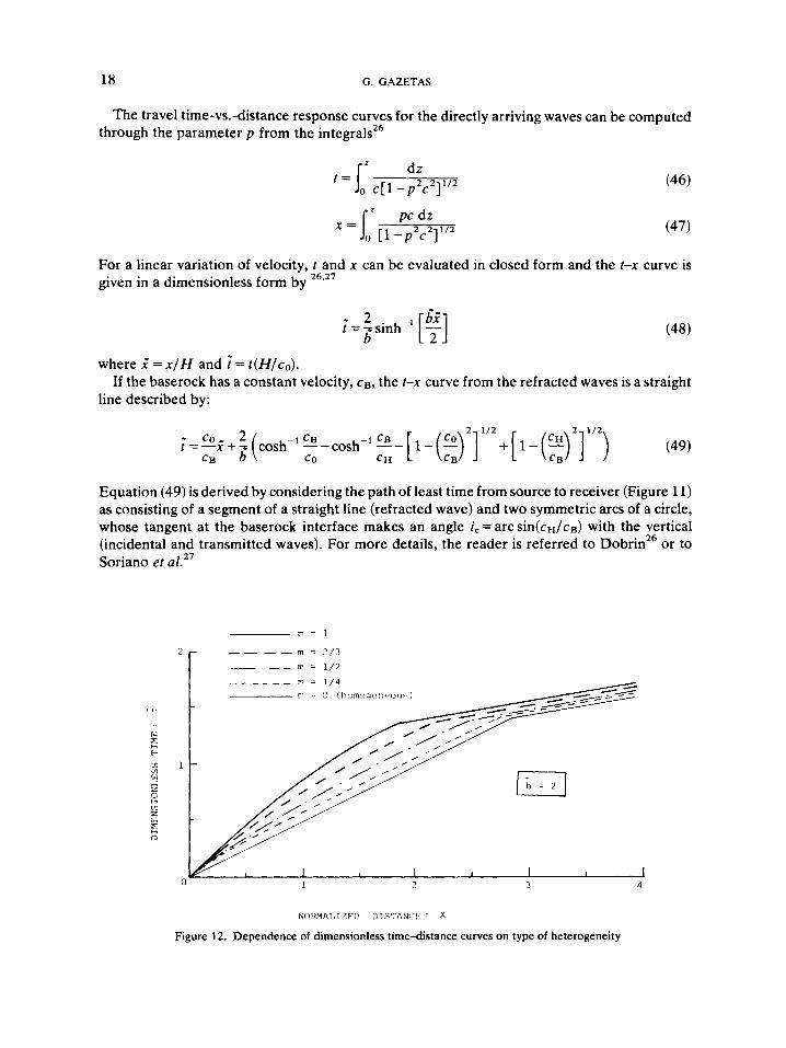
For a linear variation of velocity, t and x can be evaluated in closed form and the t-x curve is given in a dimensionless form by 26*27
where x '=x /H and ?= t (H/co) .
line described by: If the baserock has a constant velocity, cB, the t-x curve from the refracted waves is a straight
2 112 2 112
(49) r=--i+-(cosh- - co 2 1 CB --cosh-'*--[l-(:) ] +[1-(2) ] ) CB b co CH
Equation (49) is derived by considering the path of least time from source to receiver (Figure 11) as consisting of a segment of a straight line (refracted wave) and two symmetric arcs of a circle, whose tangent at the baserock interface makes an angle i, = arc sin(cH/ca) with the vertical (incidental and transmitted waves). For more details, the reader is referred to Dobrin26 or to Soriano et a1.27
Nn3w!I,r7i'r> [>IS7h:J:'! : x
Figure 12. Dependence of dimensionless time-distance curves on type of heterogeneity

VIBRATIONAL CHARACTERISTICS OF SOIL DEPOSITS 19
For the other three types of heterogeneity under consideration (i.e. p = 2/3,1/2 and 1/4) i and .? can only implicitly be related, after evaluation of the integrals in (46) and (47). The resulting ?-2 curves of the four heterogeneous deposits have been compared with the travel- time curve of an 'equivalent' homogeneous deposit. Figure 12 portrays such a comparison for a typical value of the dimensionless rate of heterogeneity, 6' = 2.
CONCLUSIONS
A systematic investigation has been presented of the vibrational behaviour of four realistic types of heterogeneous deposits with wave-velocities increasing from surface to baserock in propor- tion to (1 + pz)" ; p is a positive variable expressing the degree of heterogeneity, while m takes the values 1,2/3,1/2 and 1/4 and describes the type of heterogeneity of the deposit. Analytical and analytical-numerical methods have been presented to study the dynamic behaviour of such deposits due to vertical-shear or Rayleigh waves. Extensive parametric studies have shown that as the type and rate of heterogeneity increase, the mode shapes of the deposit in horizontal vibrations show a sharper attenuation with depth, whereas the fundamental period of the deposit becomes only slightly lower than the corresponding period of a homogeneous deposit with the same average velocity. The decay with depth of Rayleigh-wave-induced vibrations has been found to depend on the surface wave velocity, the type and rate of heterogeneity, but also on the range of vibrational frequencies that are of interest. The importance of the above results has been illustrated in connection with the problem of foundation isolation from ground- transmitted vibrations and the method of subsurface soil exploration through the steady-state surface vibration technique. Finally, the background has been set for the proper interpretation of the travel time-vs.-distance curves from seismic refraction surveys of heterogeneous soil deposits.
LIST OF SYMBOLS
Latin A(z , o), A(ao) = amplification function (i.e., ratio of Fourier amplitude spectra)
a. = dimensionless frequency factor (equation (29)) b = rate of heterogeneity of deposit with linear va.riation of velocity 6 = dimensionless rate of heterogeneity: b = bH c = S-wave velocity: c = co(l + gz)"; also, phase velocity of surface waves
CO, cH = S-wave velocities at top and bottom of a deposit, respectively C R = R-wave velocity f = frequency of vibration: f = w / 2 ~
H =thickness of soil deposit (Figure 1) G = shear modulus of soil: G = Go(l +pz)'"'
Jv, Yv; Iv, Kv = regular and modified Bessel functions of order V, first and second kind, respectively
LR = Rayleigh wave-length T = dimensionless time factor: = t (H/co)
u, w =horizontal and vertical displacements U, W = normalized u and w (equation (35))
x ' = x / H i = z / H
20
Greek
G. GAZETAS
CL = rate of heterogeneity, in general: c = co( 1 + pz)”’ CZ = p H dimensionless rate of heterogeneity v = Poisson’s ratio p = material density w = circular frequency
REFERENCES
1. V. Chiang-Liang, ‘Dynamic response of structures in layered soils’, Res. Rep. R74-10, M n , No. 335 (1974). 2. G. Gazetas and J. M. Rwsset, ‘Vertical vibrations of machine foundations’, J. Georech. Engng Div., ASCE, 105,
3. E. Kausel, ‘Forced vibrations of circular footings on layered media’, Res. Rep. R74-11, MIT, No. 336 (1974). 4. F. E. Richart, R. D. Woods and J. R. Hall, Vibrations of Soils and Foundations, Prentice-Hall, Englewood Cliffs,
5. J. Lysmer and G. Waas, ‘Shear waves in plane infinite structures’, J. Engng Mech. Div., ASCE, 98, EM1 (1972). 6. J. M. Roesset, ‘Soil amplification of earthquakes’, in Numerical Methods in Geotechnical Engineering, Eds. Desai
7. R. Dobry, I . Oweis and A. Urzua, ‘Simplified procedures for estimating the fundamental period of a soil profile’,
8. G. Gazetas and M. K. Yegian, ‘Shear and Rayleigh waves in soil dynamics’, J. Georech. Engng Div., ASCE, 105,
9. J. Lysmer, ‘Analytical procedures in soil dynamics’. Proc. Spec. Conf. on Soil Dyn. and Earthq. Eng., ASCE,
10. G. Dahlquist and A. Bjork, Numerical Merhods, Prentice-Hall, Englewood Cliffs, New Jersey, 1974 (translated
11. H. Schreyer, ‘One-dimensional elastic waves in inhomogeneous media’, J. Engng Mech. Din , ASCE, 103, EM5
12. N. N. Ambraseys, ‘A note on the response of an elastic overburden of varying rigidity to an arbitrary ground
13. K. Toki and S. Cherry, ‘Inference of subsurface accelerations and strain from accelerograms recorded at ground
14. R. P. Brent, Algorirhms for Minimization wirhour Derivation, Prentice-Hall, Englewood Cliffs, New Jersey, 1973. 15. W. T. Thomson, ‘Transmission of elastic waves through a stratified soil medium’, J. Applied Phys. 21 (1950). 16. N. A. Haskell, ‘The dispersion of Rayleigh waves in multilayered elastic media’, Bull. Seism. SOC. Am. SO,
17. J. D. Achenbach, Wave Propagation in Elasric Solids, North-Holland, Amsterdam, 1973. 18. J. F. Hook, ‘Separation of the vector wave equation of elasticity for certain types of inhomogeneous, isotropic
19. R. N. Gupta, ‘Reflection of elastic waves from a linear transition layer’ Bull. Seism. SOC. Am. 56.51 1-526 (1966). 20. G. Gazetas, ‘Static and dynamic displacements of foundations on heterogeneous multi-layered soils’, Giotechnique,
21. G. N. Watson, Theory of Bessel Functions, 2nd edition, Cambridge University Press, Cambridge, England, 1952. 22. A. A. Maxwell and Z. B. Fry, ‘A procedure for determining elastic moduli of in-site soils by dynamic techniques’,
Proc. Int. Symp. Wave Prop. Dyn. Prop. Earth Mar., Univ. New Mex., Albuquerque, N.M., 213-220 (1967). 23. W. F. Marcuson and J. R. Curro, ‘Field and laboratorydetermination of soil moduli’, Geoph. Merh. Georechn. Eng.,
ASCE Conv., Atlanta, 243-277 (1979). 24. R. D. Woods, Measurement of dynamic soil properties’, Proc. ASCE Spec. Conf. on Earrhq. Eng. Soil Dyn. I,
91-178, Pasadena, Cal. (1978). 25. D. Raghu, ‘A new technique to determine R-wave velocities’, Geoph. Merh. Geotech. Eng., ASCE Conv., Atlanta,
26. M. B. Dobrin, Introducrion to Geophysical Prospecting, 3rd edition, McGraw-Hill, New York, 1976. 27. A. Soriano, R. J. Krizek and A. G. Franklin, ‘Seismic refraction surveying in soils with variable propagation
GT12 (1979).
New Jersey, 1970.
and Christian, McGraw-Hill, New York, 1977.
Bull. Seism. SOC. Am. 66 (1976).
GT12, (1979).
Pasadena, CA, 111,1267-1316 (1978).
from Swedish).
(1977).
motion’, Bull. Seism. SOC. Am. 49 (1959).
surface’, Proc. 4rh Europ. Symp. on Earrhq. Eng., London (1972).
4147-4150 (1960).
media’, J. Acousr. SOC. Am. 33, 302-313 (1961).
30,159-177 (1980).
279-292 (1979).
velocity’, Soils and Found. 17, 1-15 (1977).