vidalta cable stayed bridge - cfcsl · we have seen that one of the basic prerequisites of...
TRANSCRIPT

Vidalta Cable-stayed Bridge
Leonardo FERNÁNDEZ Ph. M. Sc. Civil and Structural Engineer Carlos Fernández Casado, S.L. Madrid, Spain [email protected]
Lucía FERNÁNDEZ M. Sc. Civil and Structural Engineer Carlos Fernández Casado, S.L. Madrid, Spain [email protected]
Antonio CANO M. Sc. Civil and Structural Engineer Carlos Fernández Casado, S.L. Madrid, Spain
José CUERVO Civil Engineer Carlos Fernández Casado, S.L. Madrid, Spain
Summary
The Vidalta Bridge is located on the outskirts of Mexico City, in a very deep valley with special conditions, which led to the creation of a unique cable stayed bridge.
The total span between the building, where the bridge starts, and the opposite edge of the valley is 240 m, with the possibility of locating a support at 60 m from that first edge, so therefore the bridge is split into two spans of 60 and 180 m. Because of that, the stay tower has been inclined to reduce this difference, splitting the deck in two spans of 161.5 and 78.5 m.
This difference between the two spans has let to the smallest span being heavier by means of using a concrete section, and the another span
lighter with a steel box section, to compensate the forces in the stays and achieve a balance in the tower.
A polygon of forces is created between the different elements of the bridge: towers, stays and deck, which is closed with a diagonal beam joining the foundation with the shorter span’s edge, achieving the global balance of the structure.
This bridge is the recipient of the 2013 Post-tensioning Institute (PTI, USA) award of Excellence.
Keywords: Cable-stayed bridge, concrete, steel, inclined tower, free cantilevers construction.
Fig. 1. General view of the bridge
1. General outline of the project
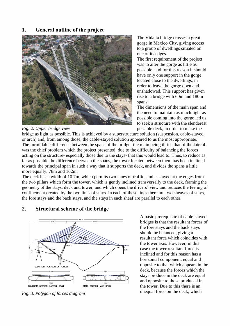
The Vidalta bridge crosses a great
gorge in Mexico City, giving access
to a group of dwellings situated on
one of its edges.
The first requirement of the project
was to alter the gorge as little as
possible, and for this reason it should
have only one support in the gorge,
located close to the dwellings, in
order to leave the gorge open and
unshadowed. This support has given
rise to a bridge with 60m and 180m
spans.
The dimensions of the main span and
the need to maintain as much light as
possible coming into the gorge led us
to seek a structure with the slenderest
possible deck, in order to make the
bridge as light as possible. This is achieved by a superstructure solution (suspension, cable-stayed
or arch) and, from among those, the cable-stayed solution appeared to us the most appropriate.
The formidable difference between the spans of the bridge- the main being thrice that of the lateral-
was the chief problem which the project presented; due to the difficulty of balancing the forces
acting on the structure- especially those due to the stays- that this would lead to. Thus, to reduce as
far as possible the difference between the spans, the tower located between them has been inclined
towards the principal span in such a way that it supports the deck, and divides the spans a little
more equally: 78m and 162m.
The deck has a width of 10.7m, which permits two lanes of traffic, and is stayed at the edges from
the two pillars which form the tower, which is gently inclined transversally to the deck, framing the
geometry of the stays, deck and tower; and which opens the drivers’ view and reduces the feeling of
confinement created by the two lines of stays. In each of these lines there are two sheaves of stays,
the fore stays and the back stays, and the stays in each sheaf are parallel to each other.
2. Structural scheme of the bridge
A basic prerequisite of cable-stayed
bridges is that the resultant forces of
the fore stays and the back stays
should be balanced, giving a
resultant force which coincides with
the tower axis. However, in this
case the tower resultant force is
inclined and for this reason has a
horizontal component, equal and
opposite to that which appears in the
deck, because the forces which the
stays produce in the deck are equal
and opposite to those produced in
the tower. Due to this there is an
unequal force on the deck, which
Fig. 2. Upper bridge view
Fig. 3. Polygon of forces diagram
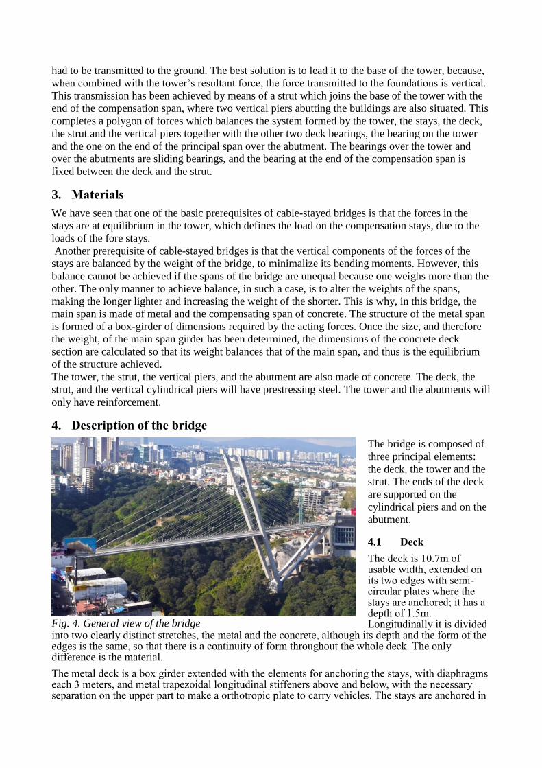
had to be transmitted to the ground. The best solution is to lead it to the base of the tower, because,
when combined with the tower’s resultant force, the force transmitted to the foundations is vertical.
This transmission has been achieved by means of a strut which joins the base of the tower with the
end of the compensation span, where two vertical piers abutting the buildings are also situated. This
completes a polygon of forces which balances the system formed by the tower, the stays, the deck,
the strut and the vertical piers together with the other two deck bearings, the bearing on the tower
and the one on the end of the principal span over the abutment. The bearings over the tower and
over the abutments are sliding bearings, and the bearing at the end of the compensation span is
fixed between the deck and the strut.
3. Materials
We have seen that one of the basic prerequisites of cable-stayed bridges is that the forces in the
stays are at equilibrium in the tower, which defines the load on the compensation stays, due to the
loads of the fore stays.
Another prerequisite of cable-stayed bridges is that the vertical components of the forces of the
stays are balanced by the weight of the bridge, to minimalize its bending moments. However, this
balance cannot be achieved if the spans of the bridge are unequal because one weighs more than the
other. The only manner to achieve balance, in such a case, is to alter the weights of the spans,
making the longer lighter and increasing the weight of the shorter. This is why, in this bridge, the
main span is made of metal and the compensating span of concrete. The structure of the metal span
is formed of a box-girder of dimensions required by the acting forces. Once the size, and therefore
the weight, of the main span girder has been determined, the dimensions of the concrete deck
section are calculated so that its weight balances that of the main span, and thus is the equilibrium
of the structure achieved.
The tower, the strut, the vertical piers, and the abutment are also made of concrete. The deck, the
strut, and the vertical cylindrical piers will have prestressing steel. The tower and the abutments will
only have reinforcement.
4. Description of the bridge
The bridge is composed of
three principal elements:
the deck, the tower and the
strut. The ends of the deck
are supported on the
cylindrical piers and on the
abutment.
4.1 Deck
The deck is 10.7m of usable width, extended on its two edges with semi-circular plates where the stays are anchored; it has a depth of 1.5m. Longitudinally it is divided
into two clearly distinct stretches, the metal and the concrete, although its depth and the form of the edges is the same, so that there is a continuity of form throughout the whole deck. The only difference is the material.
The metal deck is a box girder extended with the elements for anchoring the stays, with diaphragms each 3 meters, and metal trapezoidal longitudinal stiffeners above and below, with the necessary separation on the upper part to make a orthotropic plate to carry vehicles. The stays are anchored in
Fig. 4. General view of the bridge

the lateral elements of the girder, in tubes which transmit the forces to the girder through diaphragms.
The concrete deck is formed of two longitudinal beams at the edges, joined by an upper slab and prestressed transverse beams. As we have seen, the size of the concrete section is governed by its weight which must be sufficient to balance the vertical forces of the stays. These are anchored in the same places in the concrete section as they are in the metallic section.
An especially complex element of the deck is the end node where the deck, the strut and the vertical piers, come together. The three elements are prestressed because the piers have tension, and the strut and the deck have bending moments.
The connexion of the concrete deck and the metal deck is to be found at two meters from the deck support on the tower, with a connecting section 3m’s in length where the metal girder is concreted internally, and both materials are connected to transmit the forces, particularly the axial force, of the steel section to the concrete section.
4.2 The tower
The tower has a total length of 106.6m, and a height over its foundations at the upper end of 97m of
which 38m is from the foundations to the deck supports over the transverse beams, and 59m from
the supports to the top of the tower. It is formed of two pillars inclined towards the principal span in
the vertical plane of the axis of the bridge, and slightly inclined outwards transversally to the deck.
They are joined by a transverse beam which supports the deck.
The pillars have an almost square cross section with sides of 3m with an inset on the faces from
which the stays extend. It has a hollow section with an interior space of 1.5 x 2.3m in which the
stays are anchored. Between each level of anchors, the interior space has prestressed diaphragms
which join the faces of the anchors. These are to reduce the transverse bending moment of the sides
of the girder.
The cross section of the pillars is constant throughout their length except for a narrowing at the
level of the transverse beam and the deck.
The longitudinal reinforcement of the tower is passive throughout its length. The transversal is
strengthened by prestressing bars, which resist transverse tension generated by the stay anchors.
4.3 Strut
The strut is comprised of two inclined beams, of square cross-section, of sides 2.2m and a length from its foundations to the node of the deck and the vertical piers of 69.5m. It contains a hollow with a diameter of 1.1m and a principle prestressing to resist the dead load bending moment due to its span.
Fig. 5. Bridge under construction. Steel deck

4.4 Vertical Piers
The vertical piers are
two cylinders of
1.5m in diameter
which support the
node of the deck with
the strut. These piers
are necessary for the
equilibrium of the
system because the
horizontal force, as
we have seen the
deck generates, is
dissipated in
compression on the
strut, and in tension
on the vertical piers
so that the sum is
equal to horizontal
force of the deck. For
this reason the piers
have prestressing
throughout their length to the foundations, which in turn are anchored to the earth, by means of
prestressed anchors.
4.5 Foundation of the tower and the strut
As we have seen, the resultant of the axial forces of the tower and the strut is vertical and is
transmitted to the foundations. The foundation is direct with a depth in the earth of 8m due to the
slope of the land, and it is achieved by means of a box girder which supports the tower on one side
and the strut on the other. The base of the support has a surface area of 17x10 m.
4.6 Bearings
As we have seen, the joint of the end of the deck with the strut and the vertical piers is a rigid node
where the system of forces within the structure is in balance.
The deck, as well as by this node, is supported on the transverse beam which joins the two tower
pillars, and on the abutment at the end of the deck.
The deck bearings over the tower are sliding, and there are two horizontal bearings over the
transverse beam to transmit the vertical load, and two vertical ones between the lateral edges of the
deck and the tower pillars, to resist the traversal horizontal forces which are generated in the deck
by earthquakes.
The deck support over the abutments is oblique, which gives rise to compression and tension loads.
For this reason the supports have been made of metal struts anchored in the deck and the abutment
which allow longitudinal displacement, and compression and tension loads. As well as the struts,
vertical bearings have been placed on the edges of the deck, just as in the tower, to resist transverse
horizontal forces due to seismic events.
Structural resistance to transverse seismic effects is by means of the rigid connexion at the end of
the deck and through the bearings on the tower and the abutments. The longitudinal effects are met
by means of the same polygon of forces which balance the horizontal loads on the deck.
Fig. 6. Frontal view of the bridge

5. Construction sequence
The uniqueness of the bridge structure has necessitated a similarly unique process of construction to
maintain the equilibrium between the partial structures. The stages of this process have been the
following:
1 Construction of the foundations and the vertical piers.
2 Construction of the struts over a formwork.
3 Construction of the first section of the tower, from the foundations to the level of the
deck. It was built using climbing formwork and, to resist the forces caused by its
inclination, it was stayed at various heights from the struts.
4 Construction of the concrete deck over a formwork supported on towers over the struts
which in their turn would transmit the load to the earth through lower towers.
Once the prestressing of the deck was finished, it was left supported only by the vertical towers.
5 The erection of the metal deck, the construction of the upper part of the tower and the
installation of the stays.
The metal deck was built
by free cantilever system
from the tower to the
opposite abutment in
sections of 6m in length.
The stays were anchored
every 12m and for that
reason alternate sections
are stayed.
The erection of the metal
sections, the construction
of the upper part of the
tower, and the installation
and tensioning of the stays
was done in cycles which
required the construction of
4.38m of the tower, the erection of two 6m metal sections and the installation and tensioning of one
pair of fore stays and one pair of back stays.
This cycling was essential, because, as in all cable stayed bridges, a free cantilever requires staying
as soon as possible to reduce the forces acting on it. And in this bridge, in particular, the inclination
of the tower did not allow the construction to advance without the stabilising effect of the stays.
To finish, the free cantilever was fixed to the abutment and the bridge’s construction was complete.
Fig. 7. Bridge under construction