video display terminal reference manual - … · video display terminal reference manual railroad...
TRANSCRIPT

r
Visual Technology Incorporated
VlSUAL200 VIDEO DISPLAY TERMINAL
REFERENCE MANUAL
Railroad Avenue, Dundee Park, Andover, MA 01810, Telephone (617) 475-8056 Printed in U.S.A.

VISUAL TECHNOLOGY INCORPORATED, RAILROAD AVENUE, DUNDEE PARK, ANDOVER, MA 01810
VISUAL 200 VIDEO DISPLAY TERMI.NAL
REFERENCE MANUAL
March, 1980
VISUAL TECHNOLOGY INCORPORATED, RAILROAD AVENUE, DUNDEE PARK, ANDOVER, MA 01810
SAFETY WARNING
Hazardous voltages 115, 220 VAC and 15 KV DC are present when the terminal is on, and may remain after power is removed. Use caution when working on internal circu its, and do not work alone.
When handling the cathode ray tube caution is required as the internal phosphor is toxic. Safety goggles and gloves must be used whenever the CRT tube is handled. Should the tube break, skin or eyes exposed to the phosphor, rinse the affected area with cold water and consult a physician.
This terminal is supplied with a cord set which includes a safety ground. Do not use this terminal with an ungrounded outlet, missing ground pin, or use any adaptor which will defeat the safety ground.
Insure that power is turned off before connecting or disconnecting the keyboard cable.
This manual is published and distributed by Visual Technology Inc. Every effort has been exercised to insure its accuracy and completeness. The contents are subject to change without notice and this manual may not reflect the latest changes. Consu It the sales department for latest changes.
ii

VISUAL TECHNOLOGY INCORPORATED. RAILROAD AVENUE. DUNDEE PARK. ANDOVER. MA 01810
TASLE OF CONTENTS
Page 1. INTRODUCTION. . . . . . . . . . . . . . . . . . . . . . . . . . . . . . . . . . . . . . . . . . . . . . . . . . 1
2. INSTALLATION. . . . . . . . . . . . . . . . . . . . . . . . . . . . . . . . . . . . . . . . . . . . . . . . . . . 3 2.1 SET-UP AND CONNECTIONS .................................. 3
2.1.1 I nterface Connections ................................. 3 2.1.2 Power Cords. . . . . . . . . . . . . . . . . . . . . . . . . . . . . . . . . . . . . . . . . 3 2.1.3 Cleaning. . . . . . . . . . . . . . . . . . . . . . . . . . . . . . . . . . . . . . . . . . . . 3
2.2 TURN-ON AND WARM UP . . . . . . . . . . . . . . . . . . . . . . . . . . . . . . . . . . . . . 3 2.2.1 Power Turn-On. . . . . . . . . . . . . . . . . . . . . . . . . . . . . . . . . . . . . . . 3 2.2.2 Warm Up ........................................... 3
3. KEYBOARD AND CONTROLS ....................................... 5 3.1 REARPANELSWITCHES ..................................... 5
3.1.1 General . . . . . . . . . . . . . . . . . . . . . . . . . . . . . . . . . . . . . . . . . . . . . 5 3.1.2 Rear Panel Switches. . . . . . . . . . . . . . . . . . . . . . . . . . . . . . . . . . . 5 3.1.2.1 Baud Rate .......................................... 5 3.1.2.2 Parity. . . . . . . . . . . . . . . . . . . . . . . . . . . . . . . . . . . . . . . . . . . . . . 5 3.1.2.3 Emulation Mode. . . . . . . . . . . . . . . . . . . . . . . . . . . . . . . . . . . . . . 6 3.1.2.4 Video Mode ........................... '.' . . . . . . . . . . . . 6 3.1.2.5 Refresh Rate ........................................ 6
• 3.1.2.6 Half/Full Duplex ..................................... 6 3.1.2.7 Half Duplex Mode .................................... 6 3.1.2.8 Scroll/Page.. . . . . . . . . . . . . . . . . . . . . . . . . . . . . . . . . . . . . . . . . 7 3.1.2.9 Auto LF/CR - ADM 3A+ Space Over Data. . . . . . . . . . . . . . . . . 7 3.1.2.10 Auto New Line. . . . . . . . . . . . . . . . . . . . . . . . . . . . . . . . . . . . . . . 8 3.1.2.11 Data Terminal Ready. . . . . . . . . . . . . . . . . . . . . . . . . . . . . . . . . . 8
3.2 SLIDE CONTROLS ................ , ................... , .... " 8 3.2.1 General. . . . . . . . . . . . . . . . . . . . . . . . . . . . . . . . . . . . . . . . . . . . . 8
3.3 KEYBOARDS. . . . . . . . . . . . . . . . . . . . . . . . . . . . . . . . . . . . . . . . . . . . . . . 8 3.3.1 General. . . . . . . . . . . . . . . . . . . . . . . . . . . . . . . . . . . . . . . . . . . . . 8
3.4 EXTERNAL VIDEO .......................................... 9
4. OPERATION ............................. , .. , ..... , .............. , 13 4.1 GENERAL ................................................. , 13 4.2 CURSOR COMMANDS ....................................... , 13 4.3 TAB COMMANDS ............................ , . . . .. . . . . . . . . . .. 14 4.4 CLEAR COMMANDS ......................................... 14 4.5 ERASE COMMANDS ................................ , .... '" " 15 4.6 FORMAT COMMANDS. . . . . . . . . . . . .. . . . . . . .. . . .. . . . .. . .. . . . . .. 15 4.7 EDIT COMMANDS ........................................... 16 4.8 KEYBOARD COMMANDS ..................................... 16 4.9 GRAPHICS COMMANDS ...................................... 17 4.10 PRINTER COMMANDS ..... ' ......................... " ... , .... 17 4.11 READ COMMANDS .......................................... 18
iii

VISUAL TECHNOLOGY INCORPORATED. RAILROAD AVENUE. DUNDEE PARK. ANDOVER. MA 01810
TABLE OF CONTENTS - Continued
Page
4.12 BLOCK MODE .. , ............. , ..... , ...... " ....... '" .. , " 18 4.12.1 General ............ " ............. , ....... " ...... , 18 4.12.2 Data Transmission .................................. 20 4.12.2.1 Protect/Unprotect Mode ............................. 21 4.12.2.2 Data Compression .................................. 23 4.12.2.3 Line Mode Transmission. . . . . . . . . . . . . . . . . . . . . . . . . . . . . . 24 4.12.2.4 Pagl:! Mode Transmission. . . . . . . . . . . . . . . . . . . . . . . . . . . . . . 24 4.12.2.5 Batch Mode Transmission. . . . . . . . . . . . . . . . . . . . . . . . . . . . . 24 4.12.3 Block Mode Commands ... . . . . . . . . . . . . . . . . . . . . . . . . . . . 25 4.12.3.1 Set Block Mode Command. . . . . . . . . . . . . . . . . . . . . . . . . . . . 25 4.12.3.2 Reset Block Mode Command . . . . . . . . . . . . . . . . . . . . . . . . . . 25 4.12.3.3 Lock Block Key Command ........................... 25 4.12.3.4 Unlock Block Key Command. . . . . . . . . . . . . . . . . . . . . . . . . . 25 4.12.3.5 Set Line Mode Command ..................... ; . . . . . . . 25 4.12.3.6 Set Page Mode Command . . . . . . . . . . . . . . . . . . . . . . . . . . . . . 25 4.12.3.7 Set Batch Mode Command. . . . . . . . . . . . . . . . . . . . . . . . . . . . 26 4.12.3.8 Set Protect Command ............................... 26 4.12.3.9 Set Unprotect Command .......•.......•........ . . . . . 26 4.12.3.10 Set Auto-Tab Command. . . . . . . . . . . . . . . . . . . . . . . . . . . . . . 26 4.12.3.11 Reset Auto-Tab Command. . . . . . . . . . . . . . . . . . . . . . . . . . . . 26 4.12.3.12 Set Field Separator Command ......................... 27 4.12.3.13 Set Start of Message Code ............................ 27 4.12.3.14 Set First End of Line Code .... , ......... ' ............ " 27 4.12.3.15 Set Second End of Line Code. . . . . . . . . . . . . . . . . . . . . . . . . . 28 4.12.3.16 Set First End of Message Code. . . . . . . . . . . . . . . . . . . . . . . . . 28 4.12.3.17 Set Second End of Message Code . . . . . . . . . . . . . . . . . . . . . . . 28 4.12.3.18 Remote Transmit Command .......................... 28 4.12.4 Interrupted Transmission. . . . . . . . . . . . . . . . . . . . . . . . . . . . . 28 4.12.5 Tab Stops. . . . . . . . . . . . . . . . . . . . . . . . . . . . . . . . . . . . . . . .. 29 4.12.6 Parity Errors. . . . . . . . . . . . . . . . . . . . . . . . . . . . . . . . . . . . . . . 29 4.12.7 Programmable Function Keys ......................... 29 4.12.7.1 General. . . . . . . . . . . . . . . . . . . . . . . . . . . . . . . . . . . . . . . . . . . 29 4.12.7.2 Programmable Function Key Commands ...... " .... . . . . . 30
5. INTERFACES. . . . . . . . . . . . . . . . . . . . . . . . . . . . . . . .. • . . . . . . . . .. . . . . . . . . 33 5.1 CODE.......................................... ........... 33 5.2 ASYNCH RONOUS DATA. . . . . . . . . . . . . . .. . . . . . . . . . . . .. . . . . . . . . 33
iv

V'ISUAL TECHNOLOGY INCORPORATED. RAILROAD AVENUE. DUNDEE PARK. ANDOVER. MA 01810
TABLE OF CONTENTS - Continued
Page 5.3 FULL/HALF DUPLEX ........................................ 33
5.3.1 Full Duplex ......................................... 33 5.3.2 Half Duplex ........................................ , 33
5.4 COMMUNICATION INTERFACE ........ " . . .. . . .. . . .. . . . . . . .... 34 5.4.1 Current Loop Interface ................................ 34 5.4.2 Printer Interface. . . . . . . . . . . . . . . . . . . . . . . . . . . . . . . . . . . . .. 35
5.5 COMMUNICATIONS INTERFACE JUMPERS ..................... , 36 5.5.1 General. . . . . . . . . . . . . . . . . . . . . . . . . . . . . . . . . . . . . . . . . . . .. 36 5.5.2 Jumper Functions .................................... 36
6. SPECIFICATIONS ........ , .................... , .. . . . . .. . . .. .. . ... .. 37
7. FIRST LEVEL MAINTENANCE. . . . . . . . . . . . . . . . . . . . . . . . . . . . . . . . . . . . . .. 39 7.1 GENERAL ........................... , .... , ...... , . . . .. . . . .. 39 7.2 REAR PANEL .............................................. , 39
7.2.1 Rear Panel Removal . . . . . . . . . . . . . . . . . . . . . . . . . . . . . . . . . .. 39 7.2.2 Rear Panel Installation. . . . . . . . . . . . . . . . . . . . . . . . . . . . . . . .. 39
7.3 TOP COVER ................................................ 40 7.3.1 Top Cover Removal ............. . . . . .. . . . . . . . . . . . . . . .. 40 7.3.2 Top Cover Installation ................................. 40
7.4 PRINTED CIRCUIT BOARD REMOVAL AND INSTALLATION ....... 40 7.5 TV MONITOR PCB REMOVAL AND INSTALLATION .............. , 41 7.6 CRT AND FLYBACK REMOVAL AND INSTALLATION. .. . . .. . .. . .. 41 7.7 TV MONITOR ADJUSTMENTS ............... , .. , . . . . .. .. . . .. .. 41 7.8 110/220 VOLT SELECTION .................................... 43 7.9 TROUBLESHOOTING. . . . . . . . . . . . . . . . . . . . . . . . . . . . . . . . . . . . . . .. 44
7.9.1 Self Test. . . . . . . . . . . . . . . . . . . . . . . . . . . . . . . . . . . . . . . . . . .. 44 7.9.2 Fault Isolation ....................................... 44
8. INITIAL SETTINGS. . . . . . . . .. . . . . .. .. . . . . . . . . . . . . . . . . . . . . . . . . . . . . .. 47 8.1 INITIAL SETTINGS. . . . . . . . . . . . . . . . . . . . .. . . . . . . . . . . . . . . . . . . .. 47
8.1.1 Visual 200 (VT -52+) Mode ............................ , 47 8.1.2 ADDS 520+ Mode .................................... 47 8.1.3 Hazeltine 1500+ Mode. . . . . . . . . . . . . . . . . . . . . . . . . . . . . . . .. 47 8.1.4 ADM-3A+ Mode . . . . . . . . . . . . . . . . . . . . . . . . . . . . . . . . . . . .. 48
APPENDIX I - VISUAL 200 REMOTE COMMANDS ........................... 49
APPENDIX II - ASCII CODE CHART. . . . . . . . . . . . . . . . . . . . . . . . . . . . . . . . . . . . . . .. 51
APPENDIX 111- CURSOR ADDRESS VALUES VISUAL 200 (VT 52+), ADM 3A+ MODES. . . . . . . . . . . . . . . . . . . . . . . . . . . . . . . . . . . . . . . . .. 53
v
VISUAL TECHNOLOGY INCORPORATED, RAILROAD AVENUE, DUNDEE PARK, ANDOVER, MA 01810
TABLE OF CONTENTS - Continued
Page
APPENDIX IV - CURSOR ADDRESS VALUES ADDS 520+ MODE ............... 57
APPENDIX V - CURSOR ADDRESS VALUES HZ 1500+ MODE.......... ........ 61
APPENDIX VI ........ . . . . . . . . . . . . . . . . . . . . . . . . . . . . . . . . . . . . . . . . . . . . . . . . . . 65
Figure 3-1 Figure 3-2 Figure 3-3 Figure 34 Figure 4-1 Figure 4-2 Figure 4-3 Figure 5-1 Figure 5-2 Figure 5-3 Figure 54 Figure 7-1 Figure 7-2 Figure 7-3 Figure 74
LIST OF FIGURES
Rear Panel Switches . . . . . . . . . . . . . . . . . . . . . . . . . . . . . . . . . . . . . . . . . . 5 Keyboards ................................................. 10 Keyboard Transmitted Codes. . . . . . . . . . . . . . . . . . . . . . . . . . . . . . . . . . . 11 By Emulation and Alternate Keypad Mode. . . . . . . . . . . .. . . . . . . . . . . . 12 Format and Values of Character Messages ......................... 19 Block Mode Initialize Parameters. . . . . . . . . . . . . . . . . . . . . . . . . . . . . . . . 21 Transmit Page Example ....................................... 22 Pin Connection Definitions .................................... 34 Current Loop Connections. . . . . . . . . . . . . . . . . . . . . . . . . . . . . . . . . . . . . 35 Visual 200 Printer Interface . . . . . . . . . . . . . . . . . . . . . . . . . . . . . . . . . . . . 35 Interface Jumpers. . . . . . . . . . . . . . . . . . . . . . . . . . . . . . . . . . . . . . . . . . . . 36 Rear Panel Screw Locations. . . . . . . . . . . . . . . . . . . . . . . . . . . . . . . . . . . . 39 Top Cover Removal .......................................... 40 Location of TV Monitor Adjustments ............................ 42 110/220 Volt Selection ....................................... 43
vi
VISUAL TECHNOLOGY INCORPORATED, RAILROAD AVENUE, DUNDEE PARK, ANDOVER, MA 01810
1. INTRODUCTION
The Visual 200 Video Display Terminal is a self contained, microprocessor based terminal offering reliable, quiet, and economical performance. The Visual 200 contains many standard features which normally are offered as extra cost options. These include 7 X 9 dot matrix, Background/ Foregrou,nd, Line and Character Editing, Tabbing, Line Drawing, Cursor Addressing and Switchable Emulations. Beside the Visual 200 functionality; emulations of the DEC VT52, ADDS 520, LSI ADM 3A, and Hazeltine 1500* are incorporated in the terminal. Domestic and European power configurations are also provided.
This manual describes the features and operation of the Visual 200. Programming and application information together with first level service information is also included.
*DEC VT52 is a trademark of Digital Equipment Corp. ADDS 520 is a trademark of Applied Digital Data Systems. ADM 3A is a trademark of Lear Siegler Corp. Hazeltine 1500 is a trademark of Hazeltine Corp.


VISUAL TECHNOLOGY INCORPORATED, RAILROAD AVENUE, DUNDEE PARK, ANDOVER, MA 01810
2. INSTALLATION
2.1 SET-UP AND CONNECTIONS
Following unpacking, place the terminal so that air will freely circulate under the unit, on the rear surface, and at the top rear of the cover. Route the keyboard cable under the terminal and plug the connector into its receptacle on the back of the terminal using the locking screws provided.
2.1.1 Interface Connections
Two 25 pin female "0" connectors are provided on the rear of the terminal labeled "AUX PO RT" and "E IA". The "E IA" connector provides interfacing via RS 232C or 20 mao Current Loop for connection to the computer or modem. The "AUX PORT" connector provides RS 232 interfacing for a serial printer. Section 5 contains detailed interface information including pin assignments.
2.1.2 Power Cords
The VISUAL 200 is provided with a three wire power cord with a U.S. or European standard plug. Each plug includes a ground pin. Do not use this terminal on an ungrounded receptacle or use any adaptor wh ich will disconnect th is grou nd.
2.1.3 Cleaning
Dirt and smudges can be removed from the terminal with common household spray cleaners and a soft cloth. Unplug the power cord before cleaning and do not allow the cleaning solution to enter any of the cabinet openings.
2.2 TURN-ON AND WARM UP
Sufficient time should be allowed for the terminal to reach room temperature before powering on. Typically, one hour is required when the terminal has been moved from a substantially colder environment.
2.2.1 Power Turn-On
The power switch is located on the right front of the terminal. When turned on, both the "CAPS ON L Y" and "ON" keys are illuminated. An internal self-test performs a program memory check sum and data memory test. Successful completion of the self-test is indicated by extinguishing of the "CAPS ONLY" light and the display of the cursor. If neither light is illuminated and a cursor does not appear press the red reset button located on the right front underside of the terminal.
2.2.2 Warm Up
Approximately 30 seconds after power on, the display will be visible with the cursor block located at the home position. Should the cursor not appear, or the "CAPS ON L Y" and "ON" keys not be illuminated, turn the power switch off and reset the circuit breaker. The circuit breaker is the red button located on the bottom of the terminal adjacent to the power switch. Whenever the power switch is cycled, allow 30 seconds in the off position to insure proper resetting.
3

VISUAL TECHNOLOGY INCORPORATED, RAILROAD AVENUE, DUNDEE PARK, ANDOVER, MA 01810
3. KEYBOARD AND CONTROLS
3.1 REAR PANEL SWITCHES
3.1.1 General
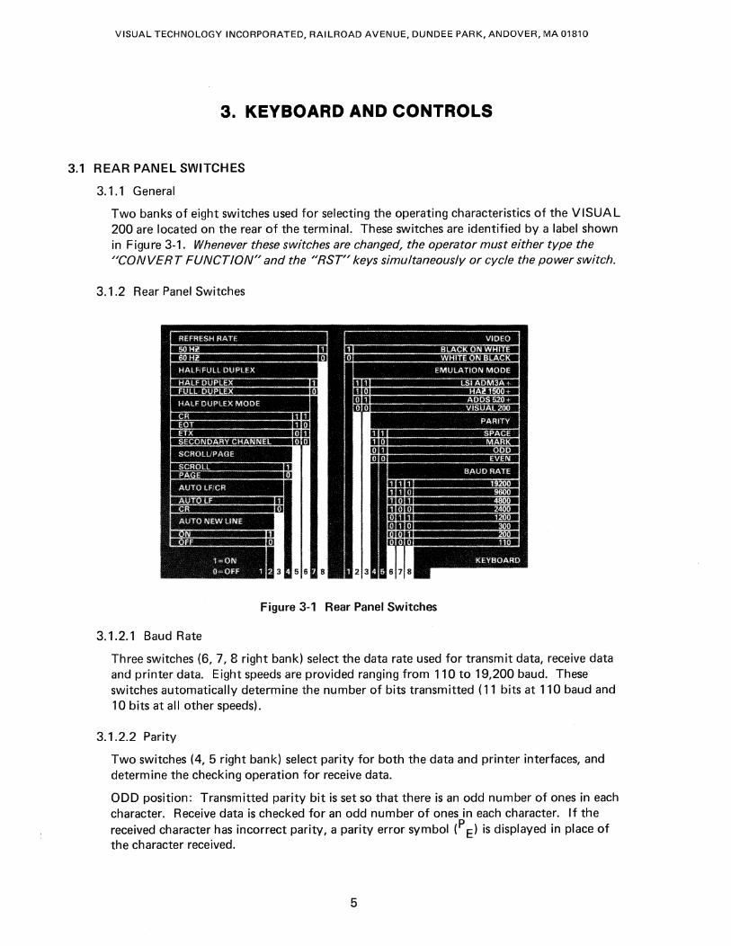
Two banks of eight switches used for selecting the operating characteristics of the VISUAL 200 are located on the rear of the terminal. These switches are identified by a label shown in Figure 3-1. Whenever these switches are changed, the operator must either type the "CONVERT FUNCTION" and the "RST" keys simultaneously or cycle the power switch.
3.1.2 Rear Panel Switches
Figure 3-1 Rear Panel Switches
3.1.2.1 Baud Rate
Three switches (6, 7, 8 right bank) select the data rate used for transmit data, receive data and printer data. Eight speeds are provided ranging from 110 to 19,200 baud. These switches automatically determine the number of bits transmitted (11 bits at 110 baud and 10 bits at all other speeds).
3.1.2.2 Parity
Two switches (4, 5 right bank) select parity for both the data and printer interfaces, and determine the checking operation for receive data.
ODD position: Transmitted parity bit is set so that there is an odd number of ones in each character. Receive data is checked for an odd number of ones in each character. If the received character has incorrect parity, a parity error symbol (p E) is displayed in place of the character received.
5
VISUAL TECHNOLOGY INCORPORATED, RAILROAD AVENUE, DUNDEE PARK, ANDOVER, MA 01810
EVEN position: In like manner, the parity bit is set so that each transmitted character has an even number of ones. Received character parity is checked and the received character is displayed or in the event of incorrect parity the parity error symbol is displayed.
SPACE position: Transmitted characters have the parity set to a zero(space) in this position. Received parity is not checked.
MARK position: In a similar manner, transmitted characters have the parity bit set to a one (mark). Received parity is not checked.
3.1.2.3 Emulation Mode
Two switches (2, 3 right bank) select the emulation mode. VISUAL 200 (VT -52+), ADDS 520+, Hazeltine 1500+, and ADM -3A+ are all present in the standard term ina I. See Section 4 for operation and functionality in each of these emulation modes.
3.1.2.4 Video Mode
One switch (1 right bank) selects the video presentation, black characters on a wh ite background, or white characters on a black background.
3.1.2.5 Refresh Rate
One switch (8 left bank) selects either 50 or 60 Hz. refresh rate. This switch does not select the voltage input of 110 or 220 volts! When this switch is altered power must be cycled off then on before the switch position is recognized. See Section 7 for input voltage change instructions.
3.1.2.6 Half/Full Duplex
One switch (7 left bank) selects Full or Half duplex operation.
Full Duplex position: Request-to-Send is always true while the terminal is on line, and transmitted data is totally independent of received data (the computer must echo the data back in order for it to appear on the screen).
Half Duplex position: Transmitted data is internally echoed to the received data. Requestto-Send is set true when a key is typed on the keyboard, and remains true until reset by the RST (reset) key, the terminal is switched off line, or by the typing of the terminating code (see paragraph 3.1.2.7). RTS can also be set remotely as described in paragraph 3.1.2.7.
3.1.2.7 Half Duplex Mode
Two switches (5,6 left bank) determine the code which will set and reset RTS depending on the emulation mode .
• When the terminal is set to FDX and V200 Rei 0.11 or V210 Rei 0.03 or later firmware is installed and the PCB is revision E or later, a local hardware echo is provided when the HDX switches are set to the CR position. If local echo is not desired in FDX, the HDX switches must be set to the Secondary Channel position (OFF).
• Visual 200 mode, C R
Typing any key sets RTS. Typing CR resets RTS. Receiving a CR from the computer sets RTS.
6
VISUAL TECHNOLOGY INCORPORATED, RAILROAD AVENUE, DUNDEE PARK, ANDOVER, MA 01810
• Visual 200 mode, EOT Typing any key sets RTS. Typing CR resets RTS. Receiving an EOT from the computer sets RTS.
• Visual 200 mode, ETX Typing any key sets RTS. Typing CR resets RTS. Receiving an ETX from the computer sets RTS.
• AD DS 520+ mode, C R Typing any key sets RTS. If Auto LF = 1 CR resets RTS. If Auto LF = 0 typing LF if preceded by CR resets RTS. No remote character sets RTS.
• ADDS 520+ mode, EOT Invalid position.
• ADDS 520+ mode, ETX Typing any key sets RTS. Typing ETX resets RTS. No remote character sets RTS.
• Hazeltine 1500+ mode CR, EOT, ETX In any of the above modes any key typed sets RTS. Typing CR, EOT, or ETX resets RTS. No remote character sets RTS.
• ADM-3A+ mode, CR Invalid position.
• ADM-3A+ mode, EOT Typing any key sets RTS. Typing EOT resets RTS. No remote character sets RTS.
• ADM-3A+ mode, ETX Typing any key sets RTS. Typing ETX resets RTS. No remote character sets RTS.
3.1.2.8 Scroll/Page
One switch (4 left bank) determines if the terminal will be in the Scroll or Page mode.
Scroll Mode: When data entering the bottom line is finished (line feed or entering the 80th character with Auto New Line enabled) the screen is scrolled up one line. The previous top line is lost, and the bottom line is blank. If Auto New Line is not enabled then line feed is required to scroll. In ADM-3A+ and ADDS-520+ mode, Scroll Mode, Home is the first position of the last line.
Page Mode: Data is entered proceeding from the top to the bottom. Upon completion of the bottom line the cursor is returned to the top of the display and data entry overwrites previous data. In ADM-3A+ mode the screen will scroll after completing the bottom line.
3.1.2.9 Auto LF/CR - ADM 3A+ Space Over Data
One switch (3 left bank) determines the effect of a carriage return code in all emulation modes except ADM 3A+ mode. In the CR position the carriage return code causes the cursor to move the the left margin of the current line. In LF position the carriage return code returns the cursor to the left margin of the next line. If scroll mode is enabled and the cursor is on the bottom line scroll will occur. Caution should be exercised when setting this switch as many computer systems will automatically send a carriage return code followed by a line feed code upon receipt of a carriage return code from the terminal.
7
VISUAL TECHNOLOGY INCORPORATED, RAILROAD AVENUE, DUNDEE PARK, ANDOVER, MA 01810
I n ADM 3A+ mode this switch enables the space over data function rather than the auto LF on CR function. When set ON the space code is normally destructive (erases any data at the cursor location) until a carriage return code is received: The CR code will move the cursor to the left margin of the current line and change the space function to nondestructive. Spaces received will move the cursor to the right without erasing data (effectively a cursor right function) until a line feed character is received, at which point the line feed is executed and the space function is returned to the destructive mode. With this switch OFF the space will remain in the destructive mode, carriage return and line feed codes will be performe,.d normally.
3.1.2.10 Auto Net Line
One switch (2 left bank) enables the Auto New Line function. When set, the cursor will proceed to the first position of the next line after the 80th character is entered. When disabled, the cursor will remain in the 80th character position, overwriting this location with subsequent data until it is moved by carriage return, line feed, or cursor command. Cursor right, tab and back tab functions wrap when this switch is set.
3.1.2.11 Data Terminal Ready
One switch (1 left bank) provides a switchable Data Terminal Ready function when revision E or later PCB is installed. When this switch is off, DTR will switch with Line/Local. When this switch is on, DTR will be true as long as the terminal is powered on, independent of Line/Local.
3.2 SLIDE CONTROLS
3.2.1 General
Two slide controls are located on the bottom of the terminal to the left rear. The forward control adjusts the high intensity brightness. The rear control adjusts the low intensity brightness. Both controls are set such that minimum brightness is achieved with the controls slid toward the operator. Upon power on, the high intensity brightness is set first using data entered from the keyboard. El1tering half intensity mode and entering data will allow the adjustment of low intensity brightness.
3.3 KEYBOARDS
3.3.1 General
Two standard keyboards are available on the VISUAL 200. Figure 3-2 details the layout for the keyboard without function keys and the keyboard with function keys. The terminal is also functional as a read only device. When the keyboard is not present the terminal is initialized to the on line state. Any time any rear panel is altered on a read only configuration it will be necessary to power off the terminal and power it on in order to insure that the new switch setting has been recognized.
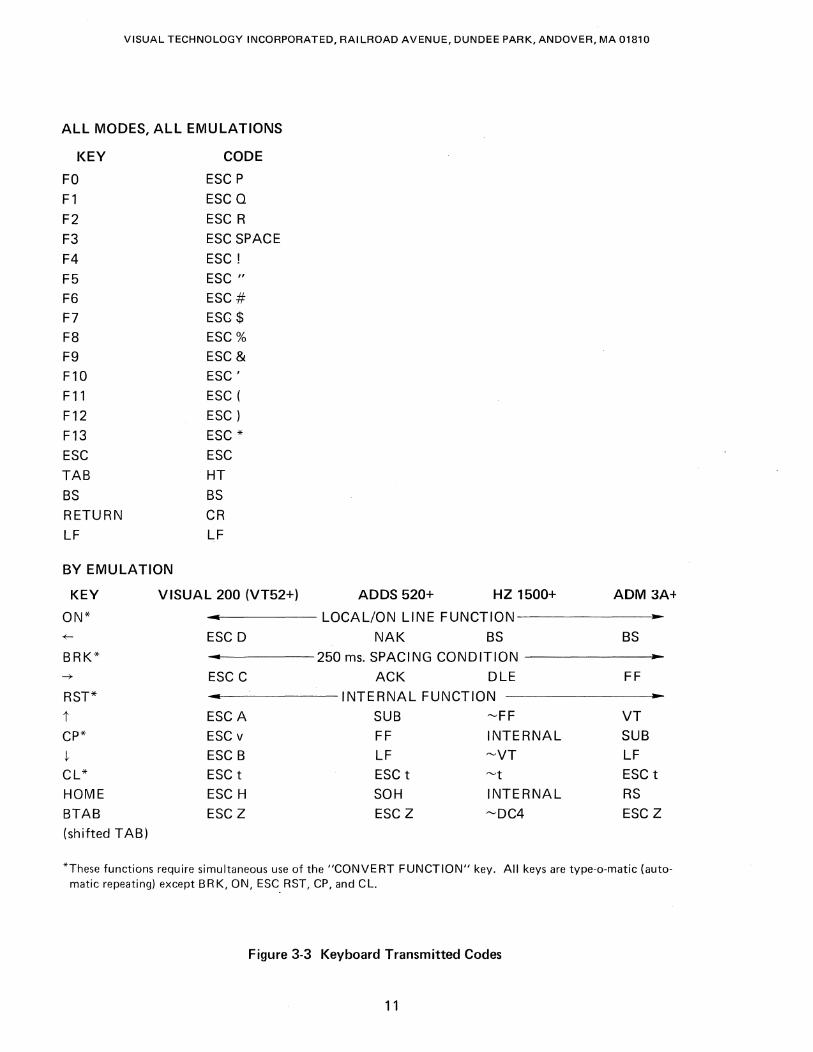
All keys except BRK, ON, ESC, RST, CP and CL have the type-o-matic feature. This feature automatically repeats the selected character for the length of time the key remains depressed after an initial delay of .75 seconds at a rate of 10 characters per second (110 baud) or 15 characters per second (150 baud or higher). Figures 3-3 and 3-4 detail the codes transmitted by each key in each of the modes of operation.
8

VISUAL TECHNOLOGY INCORPORATED, RAILROAD AVENUE, DUNDEE PARK, ANDOVER, MA 01810
The CAPS ON L Y key, when illuminated, prevents the keyboard from generating any lower case code in columns 6 and 7 of the ASCII chart, except for tilde (~) in Hazeltine mode and Delete in all modes, and converts these attempts to the equivalent upper case code. This key, in no way affects received data!
3.4 EXTERNAL VIDEO
A phono jack is provided so that the terminal can drive an external composite video input monitor. The slave monitor must be able to accept a composite video signal which is 1.5 v. p-p, 18.6 kHz horizontal line rate and have a video bandwidth of 18 MHz.
9

VISUAL TECHNOLOGY INCORPORATED, RAILROAD AVENUE, DUNDEE PARK, ANDOVER, MA 01810
STANDARD KEYBOARD
STANDARD KEYBOARD WITH FUNCTION KEY
! e e lim Il§l [ti" FO fl Fe. F3 F4 F6 Fe F7 f6 Fe flO Fn FI2 tmI 1m} , ... I NOlIE 1"'13 _ -. I ~
---------- --
( 'csc. II $ % &. ( ) fi!I Ii3 W 2 3 4 ' 5 6 7 8 9 0 A \
B. 7 8 9
TAB ( IilI [ili [5j
Q. W E· R T' y U· 0 P @ [ DEL 4 5 6
(TRI.. + * ) L'
rn! @jj §il
A' S· 0 ' F ' G' H' J K L ; . J 1 2 3
SHifT < > SHIFT s<:""-L 0 liiil ~
Z x c V B N' M
• - = C"PS ONLY
ENTER
BLOCK MODE KEYBOARD
Figure 3-2 Keyboards
10
VISUAL TECHNOLOGY INCORPORATED, RAILROAD AVENUE, DUNDEE PARK, ANDOVER, MA 01810
ALL MODES, ALL EMULATIONS
KEY CODE
FO ESC P
F1 ESC Q
F2 ESC R
F3 ESC SPACE
F4 ESC!
F5 ESC"
F6 ESC#
F7 ESC $
F8 ESC%
F9 ESC &
F10 ESC'
F 11 ESC (
F12 ESC)
F13 ESC *
ESC ESC
TAB HT
BS BS
RETURN CR
LF LF
BY EMULATION
KEY VISUAL 200 (VT52+) ADDS 520+ HZ 1500+ ADM 3A+
ON* ... LOCAL/ON LINE FUNCTION ~
*- ESC D NAK BS BS
BRK* ... 250 ms. SPACING CONDITION .. "-* ESC C ACK DLE FF
RST* ... INTERNAL FUNCTION .. t ESCA SUB ~FF VT
CP* ESC v FF INTERNAL SUB } ESC B LF ~VT LF
CL * ESC t ESC t ~t ESC t
HOME ESC H SOH INTERNAL RS
BTAB ESC Z ESC Z ~DC4 ESC Z
(shifted TAB)
*These functions require simultaneous use of the "CONVERT FUNCTION" key. All keys are type-o-matic (automatic repeating) except BRK, ON, ESC RST, CP, and CL.
Figure 3-3 Keyboard Transmitted Codes
11

VISUAL 200 (VT52+) ADDS 520+ HZ 1500+
KEY NORMAL ALT. MODE NORMAL ALT. MODE NORMAL ALT. MODE
- - ESC?m - ESC?m - ESC?m
ENTER CR ESC?M CR ESC?M CR ESC?M
0 0 ESC?p Vl ESC?p 0 ESC?p
**CPY* ESC /\ or ESC - ESC /\ or ESC - ESC /\ or ESC - ESC /\ or ESC - -' or -? -' or - ?
ESC?Q ESC?Q ESC?Q
PRT* ESC) ESC) ESC) ESC) -) - RS
. ESC?n . ESC?n . ESC?n
EL* ESC K ESC K ESC K ESC K -K -K
1 1 ESC?q 1 ESC?q 1 ESC?q
EF* ESCf ESCf ESC f ESC f -f -f
2 2 ESC?r 2 ESC?r 2 ESC?r
EP* ESC J ESC J ESC J ESCJ -J -J
3 3 ESC?s 3 ESC?s 3 ESC?s
DL* ESC M ESC M ESC M ESC M - DC3 - DC3
4 4 ESC?t 4 ESC?t 4 ESC?t
DC* ESCO ESCO ESCO ESCO -0 -0
5 5 ESC?u 5 ESC?u 5 ESC?u
CT* ESC 2 ESC 2 ESC 2 ESC 2 -2 -2
6 6 ESC?v 6 ESC?v 6 ESC?v
IL* ESC L ESC L ESC L ESC L - SUB - SUB
7 7 ESC?w 7 ESC?w 7 ESC?w
**IC* ESC i or ESC j ESC i or ESC j ESC i or ESC j ESC i or ESC j - i or - j - i or - j
8 8 ESC?x 8 ESC?x 8 ESC?x
ST* ESC 1 ESC 1 ESC 1 ESC 1 - 1 -1
9 9 ESC?y 9 ESC?y 9 ESC?y
*These functions require simultaneous use of the "CONVERT FUNCTION" key. **If not in the mode the key will xmit the first sequence. If in the mode the key will xmit the second sequence.
Figure 3-4 By Emulation and Alternate Keypad Mode
ADM3A+
NORMAL ALT. MODE
- ESC?m
CR ESC?M
0 ESC?p
ESC /\ or ESC - ESC /\ or ESC -
ESC?Q
ESC) ESC)
. ESC?n
ESC K ESC K
1 ESC?q
ESC f ESC f
2 ESC?r
ESCJ ESC J
3 ESC?s
ESC M ESC M
4 ESC?t
ESCO ESCO
5 ESC?u
ESC 2 ESC 2
6 ESC?v
ESC L ESC L
7 ESC?w
ESC i or ESC j ESCiorESCj
8 ESC?x
ESC 1 ESC 1
9 ESC?y
< (f)
c l> r ooof m ("') :c z o r o Cl -< Z ("')
o :Xl
" o :Xl l> ooof m ,0 :Xl ~ r :Xl o l> o l> < m z c ,m o c z o m m
" l> :Xl ?' l> z o o < m :Xl
s: l> ~ ~ o
VISUAL TECHNOLOGY INCORPORATED, RAILROAD AVENUE, DUNDEE PARK, ANDOVER, MA 01810
4. OPERATION
4.1 GENERAL
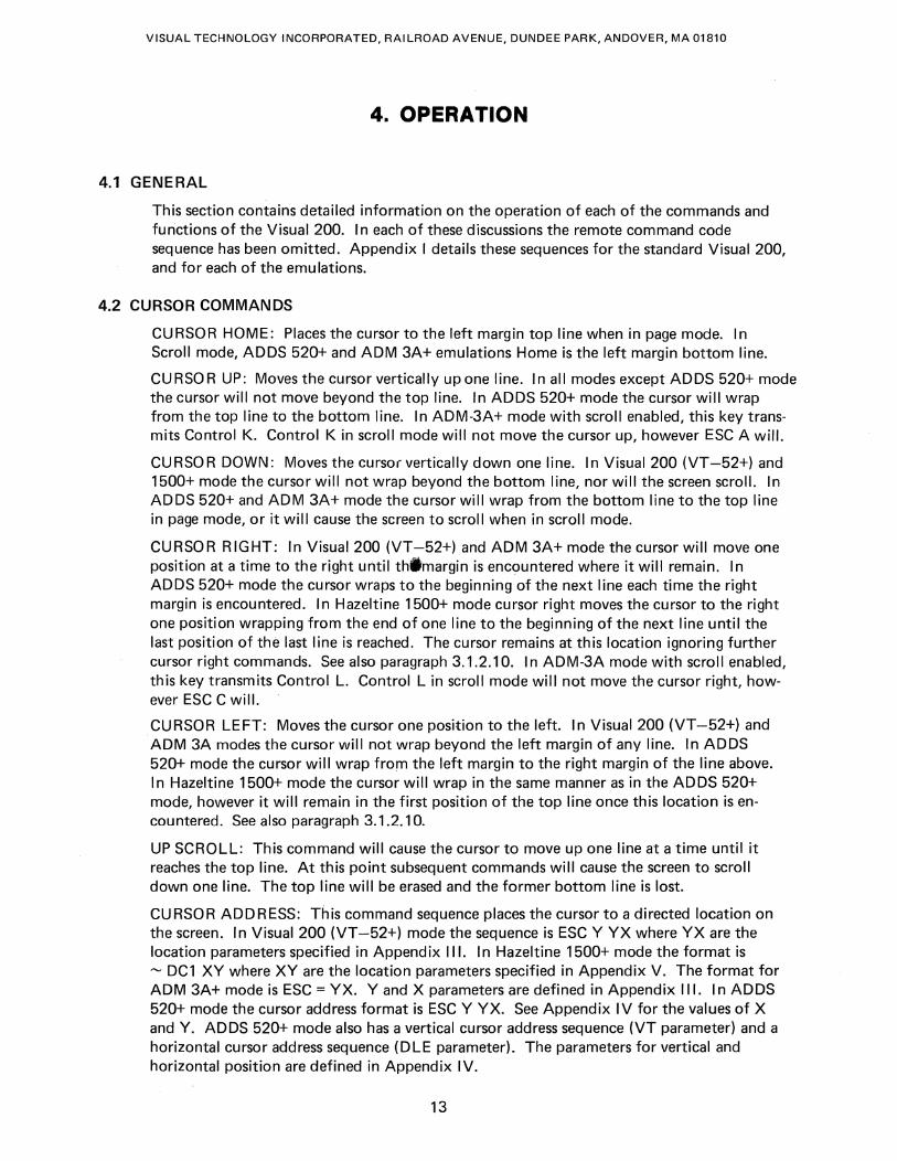
This section contains detailed information on the operation of each of the commands and functions of the Visual 200. I n each of these discussions the remote command code sequence has been omitted. Appendix I details these sequences for the standard Visual 200, and for each of the emulations.
4.2 CURSOR COMMANDS
CURSOR HOME: Places the cursor to the left margin top line when in page mode. In Scroll mode, ADDS 520+ and ADM 3A+ emulations Home is the left margin bottom line.
CURSOR UP: Moves the cursor vertically up one line. In all modes except ADDS 520+ mode the cursor will not move beyond the top line. In ADDS 520+ mode the cursor will wrap from the top line to the bottom line. In ADM-3A+ mode with scroll enabled, this key transmits Control K. Control K in scroll mode will not move the cursor up, however ESC A will.
CU RSO R DOWN: Moves the cursor vertically down one line. I n Visual 200 (VT -52+) and 1500+ mode the cursor will not wrap beyond the bottom line, nor will the screen scroll. In ADDS 520+ and ADM 3A+ mode the cursor will wrap from the bottom line to the top line in page mode, or it will cause the screen to scroll when in scroll mode.
CURSOR RIGHT: In Visual 200 (VT -52+) and ADM 3A+ mode the cursor will move one position at a time to the right until thlmargin is encountered where it will remain. In ADDS 520+ mode the cursor wraps to the beginning of the next line each time the right margin is encountered. In Hazeltine 1500+ mode cursor right moves the cursor to the right one position wrapping from the end of one line to the beginning of the next line until the last position of the last line is reached. The cursor remains at this location ignoring further cursor right commands. See also paragraph 3.1.2.10. In ADM-3A mode with scroll enabled, this key transmits Control L. Control L in scroll mode will not move the cursor right, however ESC C will.
CURSOR LEFT: Moves the cursor one position to the left. In Visual 200 (VT -52+) and ADM 3A modes the cursor will not wrap beyond the left margin of any line. In ADDS 520+ mode the cursor will wrap from the left margin to the right margin of the line above. I n Hazeltine 1500+ mode the cursor will wrap in the same manner as in the ADDS 520+ mode, however it will remain in the first position of the top line once this location is encountered. See also paragraph 3.1.2.10.
UP SCROLL: This command will cause the cursor to move up one line at a time until it reaches the top line. At this point subsequent commands will cause the screen to scroll down one line. The top line will be erased and the former bottom line is lost.
CURSOR ADDRESS: This command sequence places the cursor to a directed location on the screen. In Visual 200 (VT -52+) mode the sequence is ESC Y YX where YX are the location parameters specified in Appendix III. In Hazeltine 1500+ mode the format is ~ DC1 XY where XY are the location parameters specified in Appendix V. The format for ADM 3A+ mode is ESC = YX. Y and X parameters are defined in Appendix III. I n ADDS 520+ mode the cursor address format is ESC Y YX. See Appendix IV for the values of X and Y. ADDS 520+ mode also has a vertical cursor address sequence (VT parameter) and a horizontal cursor address sequence (DLE parameter). The parameters for vertical and horizontal position are defined in Appendix IV.
13

VISUAL TECHNOLOGY INCORPORATED, RAILROAD AVENUE, DUNDEE PARK, ANDOVER, MA 01810
READ CURSOR: Upon receipt of the read cursor command the terminal will transmit a sequence defining the current position of the cursor. In Visual 200 (VT -52+) mode, full duplex, the terminal sends Y parameter X parameter. In half duplex the YX will be followed by a carriage return. I n ADDS 520+ mode, full duplex, the message is Y parameter X parameter carriage return. I n half duplex the message is Y parameter X parameter followed by a character defined by switches 5 and 6 of the left bank of switches rear panel. ADM 3A+ mode uses the same sequences as ADDS 520+ mode, however the X and Y parameters are specified in Appendix III. I n Hazeltine 1500+ mode the read cursor message is X parameter Y parameter carriage return. X and Y values are defined in Appendix V.
4.3 TAB COMMANDS
TAB: Moves the cursor to the next tab stop. In each emulation mode there are two types of tab stops, columnar and field. A field tab stop is defined as the first foreground location following a background location. If both columnar and field tab stops are present the tab command will stop at the columnar tab stops only. If there are no tab stops on the screen the tab command will be ignored and the cursor will not move. In Visual 200 (VT -52+) mode there are additional fixed preset tab stops which are present on power on and after the reset function. These stops are at column positions 7,15,23,31,39,47,55,63, and 71 through 79. See also paragraph 3.1.2.10.
BACK TAB: Moves the cursor to the left and up one tab stop. Back tab can be generated from the keyboard by using the Tab and Shift keys. See also paragraph 3.1.2.10.
SET TAB: Set tab sets a columnar tab stop 0Wach line in the column in which the cursor is located.
CLEAR TAB: Resets the columnar tab located in the column specified by the current cursor location. All other tab stops are unaffected.
CLEAR ALL TABS: This command clears all tab stops including the preset stops in Visual 200 (VT -52+) mode. Field tab stops located after background data are unaffected.
4.4 CLEAR COMMANDS
All clear commands clear all data both foreground and background. Foreground or background mode will be retained.
CLEAR LINE: Clears all data on the entire line in which the cursor is located and places the cursor at the b!=!ginning of that line. The area cleared will be foreground spaces.
CLEAR PAGE: Clears all data on the entire screen to foreground spaces and places the cursor at the home position.
CLEAR END OF PAGE-BACKGROUND: Clears the page from the cursor location to the end of the screen to background spaces. The background/foreground mode set prior to this command is retained.
CLEAR END OF LINE: Clears all data from the cursor position to the end of the line to foreground spaces. The cursor does not move.
CLEAR TO END OF PAGE: Clears all data from the cursor position to the end of the screen to foreground spaces. The cursor does not move.
14

VISUAL TECHNOLOGY INCORPORATED, RAILROAD AVENUE, DUNDEE PARK, ANDOVER, MA 01810
4.5 ERASE COMMANDS
All erase commands clear only foreground data. Foreground/background mode is retained.
ERASE END OF FIELD: Erases foreground data to foreground spaces from the cursor to the end of the field. The cursor remains in its position.
ERASE END OF LINE: Erases foreground data to foreground spaces from the cursor position to the end of the line. The cursor does not move.
ERASE END OF PAGE: Erases foreground data to foreground spaces from the cursor position to the end of the screen. The cursor does not move.
ERASE PAGE: Erases foreground data from the entire screen. The erased areas will be set to foreground spaces. The cursor is relocated to the home position.
4.6 FORMAT COMMANDS
SET FOREG ROUND: Sets a mode where all data following the command will be displayed at full intensity. This mode remains until a set background command is received. If there is background data present on the screen, the beginning of each foreground area will be a field tab stop location.
SET BACKGROUND: This command causes all subsequent data to be displayed at reduced intensity. A potentiometer (rear most) located on the left rear underside of the terminal adjusts the intensity level of background data.
SET SECURITY: This command causes subsequent data to be blanked (not displayed) from the screen.
RESET SECURITY: This command causes subsequent data to be displayed.
BLINK LINE: This command causes the line in which the cursor is located to blink at a 5 Hz. rate. Only one line on the screen can blink. If one line is blinking and this command is issued with the cursor on another line, the first line will cease blinking and the line in which the cursor is located will now blink. Moving the cursor from the blinking line does not affect the function. The line which is blinking is fixed in location in-so-far as scrolling is concerned. When the screen is scrolled up or down new data will enter the blink area rather than the blink area moving with the data.
STOP BLINK: The stop blink command will reset the blink function. The cursor need not be located on the blinking line.
SLOW SCROLL ENABLE: This command enables the slow scroll function wherein the screen will scroll at a slow smooth rate rather than a quick rate. This mode is particularly useful at the lower data rates and long messages, allowing the operator to easily read the data. On power up and reset the terminal is set in the slow scroll mode.
SLOW SCROLL DISABLE: Disables slow scroll and places the terminal in the traditional fast scroll mode.
SET HOLD SCREEN: This command places the terminal in the hold screen mode. After entering the mode, data will be displayed until the point when the screen would normally scroll (LF, CUrsor Down in ADDS 520+ and ADM-3A+ modes, Cursor Right in ADDS 520+ mode when at the right margin, receipt of the 80th character on the bottom line with Auto New Line set, or receipt of CR with Auto LF set). The character which would cause
15

VISUAL TECHNOLOGY INCORPORATED, RAILROAD AVENUE, DUNDEE PARK, ANDOVER, MA 01810
the scroll is stored in the buffer and an XOF F (DC3) code is transmitted. Data received from this point on is also stored in the buffer.
When the operator types the scroll key, the scrolling character is extracted from the buffer, causing the screen to scroll. Data continues to be extracted from the buffer and displayed until the next scrolling character is encountered or until the buffer empties. If the buffer empties, an XON (DC1) code is transmitted. If another scrolling character is encountered, the emptying of the buffer halts with that scrolling character as the first character remaining in the buffer. When the operator again types the scroll key, extraction begins and continues line by line until the buffer empties.
Using the shift key with the scroll key modifies the operation from a line by line basis to a page (24 line) basis. When shifted scroll is used, all data from the buffer is scrolled onto the screen, an XON (DC 1) is sent at the time the buffer empties, and new data is scrolled onto the screen as received, until a total of 24 lines have been displayed. When the 24th line is displayed, the terminal transmits an XOFF (DC3) and places subsequent data into the buffer. Scroll or shifted scroll functions are then repeated.
RESET HOLD SCREEN: This command resets the hold screen mode immediately if the operator has previously scroll.ed all buffer data onto the screen (the computer has received an XON). If buffered data has not be~n scrolled onto the screen when the command is received, the command will be stored in the buffer and acted upon only when the operator has scrolled that line onto the screen.
4.7 EDIT COMMANDS
INSERT LINE: The insert line command causes the data on the entire line in which the cursor is located and all lines below this line to move down one line. The bottom line is lost and the line where the cursor is located is blank. The cursor is positioned at the beginning of the blank line.
DELETE LINE: The delete line command deletes the line in which the cursor is located, moves all lines below this line up one line, and places the cursor on the left margin.
INSERT CHARACTER: Insert character function is a mode enabled by the set insert character command and is disabled by the reset insert character command. Once in the mode, an input character will move the data starting at the cursor location right one position, place the new character at the cursor location, and move the cursor one position to the right. Data moving to the right margin will be lost. Where half intensity data is present to the right of the insert point data moving to the right will be lost at the beginning of the half intensity area. When the cursor reaches the half intensity data, it will overwrite the half intensity area because in the character mode unit half intensity data is not protected. The bell will ring on each character entered from the keyboard.
DELETE CHARACTER: The delete character command deletes the character at the cursor location and moves high intensity data located to the right of the cursor one position to the left. Only data onthe line which contains the cursor is affected.
4.8 KEYBOARD COMMANDS
LOCK KEYBOARD: The keyboard lock command is effective only when the terminal is on line. The lock command inhibits all operation of the keyboard except reset (RST) which will cause the keyboard to unlock.
16

VISUAL TECHNOLOGY INCORPORATED, RAILROAD AVENUE, DUNDEE PARK, ANDOVER, MA 01810
UNLOCK KEYBOARD: The unlock command resets the keyboard lock function and allows full use of the keyboard. All keyboard modes previously established (caps only, on line, etc.) are not reset by this command.
SET PAD FUNCTION: The set pad function sets a mode wherein the keys on the numeric pad transmit an alternate code sequence when typed. Figure 3-4 defines both the normal mode codes and the alternate mode sequences for each of the numeric pad keys in each of the emulation modes. The alternate mode remains active until reset by the reset pad function command, power off, or reset function.
4.9 GRAPHICS COMMANDS
SET GRAPHICS: The set graphics and reset graphics command set and reset a mode wherein subsequently received chara~ters from column 6 and 7 (lower case codes) of the ASCII chart are displayed as graphic elements rather than characters. Appendix II defines the elements found in the Visual 200. The numeric digits found in this chart are subscripts. In Hazeltine 1500+ mode the tilde ("-') is used as the lead in character. The paragraph symbol is therefore generated by the carat (1\) code. Please note that each character location on the screen can contain only one code (a graphic symbol can not simultaneously occupy the same location as an alpha or numeric).
4.10 PRINTER COMMANDS
COPY ON: This command enables received data to appear on the screen, while simultaneously being sent to the printer through the printer port. The computer system must insert appropriate pad characters required by the printer. The data rate is that rate selected for the terminal (Right Bank of Switches, switches 6, 7, 8). In like manner the parity selection of the terminal is the same for the printer.
COpy OFF: The copy off command disables the data path from the terminal interface to the printer port. Whenever this command sequence is sent by the computer while the terminal is in the copy on mode the sequence will arrive at the printer before the terminal disconnects the copy output.
TRANSPARENT ON: This mode operates in a manner similar to Copy On, except that received data is sent only to the printer. The CRT screen does not receive any data while in this mode.
TRANSPARENT & COpy OFF: This command resets either or both the copy on function or the transparent on function.
P R I NT PAG E: The print page command causes the contents of the screen to be printed through the printer port. The printer in this mode operates at the same baud rate and parity as the communications interface. Printing takes place from home up to, but not including, the character at the cursor position. If the cursor is placed at the home position prior to issuing the print page command the entire page will be printed. Data compression is initiated on a line by line basis with a carriage return code and line feed code automatically inserted at the completion of each line. When printing only a portion of a page the cursor should be placed at the left margin of the line following the last line to be printed. This insures that the last line is completely printed including the carriage return and the line feed.
17
VISUAL TECHNOLOGY INCORPORATED, RAILROAD AVENUE, DUNDEE PARK, ANDOVER, MA 01810
4.11 READ COMMANDS
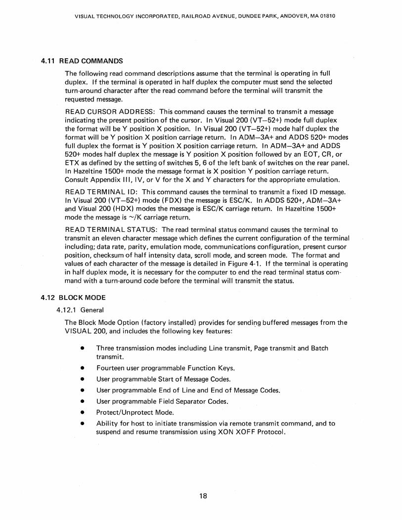
The following read command descriptions assume that the terminal is operating in full duplex. If the terminal is operated in half duplex the computer must send the selected turn-around character after the read command before the terminal will transmit the requested message.
READ CURSOR ADDRESS: This command causes the terminal to transmit a message indicating the present position of the cursor. In Visual 200 (VT -52+) mode full duplex the format will be Y position X position. In Visual 200 (VT -52+) mode half duplex the format will be Y position X position carriage return. In ADM-3A+ and ADDS 520+ modes full duplex the format is Y position X position carriage return. In ADM-3A+ and ADDS 520+ modes half duplex the message is Y position X position followed by an EaT, CR, or ETX as defined by the setting of switches 5, 6 of the left bank of switches on the rear panel. I n Hazeltine 1500+ mode the message format is X position Y position carriage return. Consult Appendix III, IV, or V for the X and Y characters for the appropriate emulation.
READ TERMINAL 10: This command causes the terminal to transmit a fixed ID message. In Visual 200 (VT -52+) mode (FDX) the message is ESC/K. In ADDS 520+, ADM-3A+ and Visual 200 (H DX) modes the message is ESC/K carriage return. I n Hazeltine 1500+ mode the message is ~/K carriage return.
READ TERMINAL STATUS: The read terminal status command causes the terminal to transmit an eleven character message which defines the current configuration of the terminal including; data rate, parity, emulation mode, communications configuration, present cursor position, checksum of half intensity data, scroll mode, and screen mode. The format and values of each character of the message is detailed in Figure 4-1. If the terminal is operating in half duplex mode, it is necessary for the computer to end the read terminal status command with a turn-around code before the terminal will transmit the status.
4.12 BLOCK MODE
4.12.1 General
The Block Mode Option (factory installed) provides for sending buffered messages from the VISUAL 200, and includes the following key features:
• Three transmission modes including Line transmit, Page transmit and Batch transmit.
• Fourteen user programmable Function Keys.
• User programmable Start of Message Codes.
• User programmable End of Line and End of Message Codes.
• User programmable Field Separator Codes.
• Protect/Un protect Mode.
• Ability for host to initiate transmission via remote transmit command, and to suspend and resume transmission using XON XOF F Protocol.
18

VISUAL TECHNOLOGY INCORPORATED, RAILROAD AVENUE, DUNDEE PARK, ANDOVER, MA 01810
DATA RATE SWITCH
110 0
200 300 2
1200 3
2400 4
4800 5 9600 6
19200
PARITY SWITCH
EVEN @
ODD A
MARK B
SPACE C
MODE SWITCH
VISUAL 200 IVT -52+) 0 ADDS 520+
Hazeltine 1500+ 2 ADM-3A+ 3
DUPLEX SWITCH
FDX SEC. CH. @
HDXSEC. CH. A FDX ETX B HDX ETX C FDX EDT D HDX EDT E
FDX CR F
HDX CR G
NEW LINE, LF/CR, SCROLL
CHAR. AUTO N.L. AUTO CR/LF
0 0 0
1 0 0
2 0
3 0 4 0 5 0
6
NOTE: a indicates function inactive
1 indicates function active
SCROLL
0 1
0
0 1
0
2A2@7@AA6B
J T CURSOR ADDRESS
MODE FOX
VISUAL 200 IVT -52+) YX
ADDS 520+, ADM-3A+ YXCR
Hazeltine 1500+ XY CR
CHECKSUM SCREEN HALF INTENSITY DATA
@@ (high order 4 bits, low order 4 bits)
MODE
CHAR. GRAPHICS HALF INT. SECURITY HOLD SCREEN
@ 0 0 0 0
A 0 0 0 0 B 0 0 0
C 0 0 0
0 0 0 0
E 0 0 0
F 0 0 1 G 0 0 H 0 0 0
0 0 0
0 0
K 0 0 1
L 0 0
M 0 0
N 0
D 0 1 1 P 0 0 0 Q 0 0 0
R 0 0
S 0 0
T 0 0
U 0 0 V 0
W 0
X 0 0 Y 0 0
Z 0 [ 0
\ 0
1 0
1\
Figure 4-1 Format and Values of Character Messages
19
HDX
YXCR
YX duplex sw
XYCR
INS. CHAR.
0
0
1
0
0
1
0
1
0 1
0
0
0
1
0
0
1
0
0
0
1
0 1
0

VISUAL TECHNOLOGY INCORPORATED, RAILROAD AVENUE, DUNDEE PARK, ANDOVER, MA 01810
When the Block Mode Option is installed, two new key caps are installed on the keyboard. These keys will perform their normal Character mode functions if depressed alone. If depressed in conjunction with the CONVERT FUNCTION key their functionality is modified.
•
This key, when depressed in conjunction with the CONVERT FUNCTION key, will alternately enter and exit Block mode. The terminal will power-up in Character mode. When Block mode is entered, the LED on the B L key will be illuminated.
NOTE
The operator may be inhibited from changing between Btock/Character modes via the B L key. See Section 4.12.3.3 .
This key, when depressed in conjunction with the CONVERT FUNCTION key, will cause transmission to begin, provided the terminal is in Block mode.
All the standard emulations, V200 (VT -52+), HZ1500+, ADDS 520+, ADM 3A+ are operative when Block mode is entered, i.e. the terminal still responds to the control code set of the particular emulation selected by the rear panel switches.
The only Character mode commands which are altered are as follows:
• In HZ1500+ and V200 modes, the Insert and Delete Line commands are recognized and performed only when th~ terminal is in Unprotect mode.
• Hold Screen mode is not allowed in Block mode. The Set and Reset Hold Screen mode commands will not be recognized in Block mode.
• I n HZ 1500+ mode, the Transparent On command is ~5, as opposed to ~*. Th is is true for all Block mode terminals, regardless whether Block or Character mode is selected.
• Tab Stops will function as described in Section 4.12.5.
4.12.2 Data Transm ission
When operating in Block mode, data transmission will begin when the operator depresses the SEND key in conjunction with the CONVE RT FUNCTION key or when transmission is initiated via remote command from the host. The actual data transmitted is dependent on several factors.
• Transmission Mode selected (Line, Page, Batch).
• Status of Protect/Unprotect Mode.
• Field Separator selected.
• Start of Message Code, End of Line Code (s) and End of Message Code (s) selected.
20

VISUAL TECHNOLOGY INCORPORATED, RAILROAD AVENUE, DUNDEE PARK, ANDOVER, MA 01810
The power-up parameters for these factors will vary depending on the emulation mode selected. When the terminal is initialized in Block mode, Power-on followed by Set Block command, or CONVERT FUNCTION RST followed by Set Block mode command, the parameters will remain set unless programmed otherwise. Toggling between Block and Character modes will not reset the programmable parameters, i.e. Start of Message, Field Separator, End of Line, and End of Message codes.
Function Key Emulation XMIT Protect Display Auto Field End of Line End of Transmission Transmit
Mode Mode Mode Mode Tab Separator First Second First Second Sequence
V200 Line Yes Foreground No HT CR LF Rear Panel None Per Figure 3.3 Switch
LSI ADM-3A+ Line Yes Foreground No FS US None Rear Panel None Per Figure 3.3 Switch
ADDS 520+ Line Yes Foreground No HT CR LF Rear Panel None Per Figure 3.3 Switch
HZ1500+ Batch No Background No None CR None Rear Panel None Per Figure 3.3 Switch
Figure 4-2 Block Mode Initialize Parameters
Rear Panel Switch refers to Left Bank switches 5, 6 (Half Duplex mode), which may select CR, 'EaT or ETX as the initiated End of Message code.
4.12.2.1 Protect/Unprotect Mode
The VISUAL 200 may display data in either full-intensity (foreground) or half-intensity (background) as described in Section 4.6. The Protect/Un protect mode provides the choice of having background data protected or unprotected.
If the Protect/Unprotect mode is set to protect, background data on the screen will be protected. If the Protect/Un protect mode is set to unprotect, all data (foreground and background) on the screen will be unprotected.
Protected data is not alterable by the operator from the keyboard. If the operator attempts to alter protected data, the events as described in Sections 4.12.3.10 and 4.12.3.11 will occur.
Protected data cannot be transmitted. If an area of the screen that contains a protected field is transmitted, the protected field will not be transmitted, but will be replaced with a Field Separator code. (The Field Separator code is set on power-up as described in Figure 4-2, but may also be programmed to be any ASCII character excluding null as described in Section 4.12.3.12).
If it is desired to transmit background data, the terminal must be set to Unprotected mode. In th is case, all data on the screen, background and foreground, is unprotected and is thus transmittable. When transmitting a message in Unprotect mode, field separators are not needed and are thus omitted from the data-stream. Instead, the code sequence for entering/ exiting background fields are appended at the beginning and end of the background fields
21
VISUAL TECHNOLOGY INCORPORATED, RAILROAD AVENUE, DUNDEE PARK, ANDOVER, MA 01810
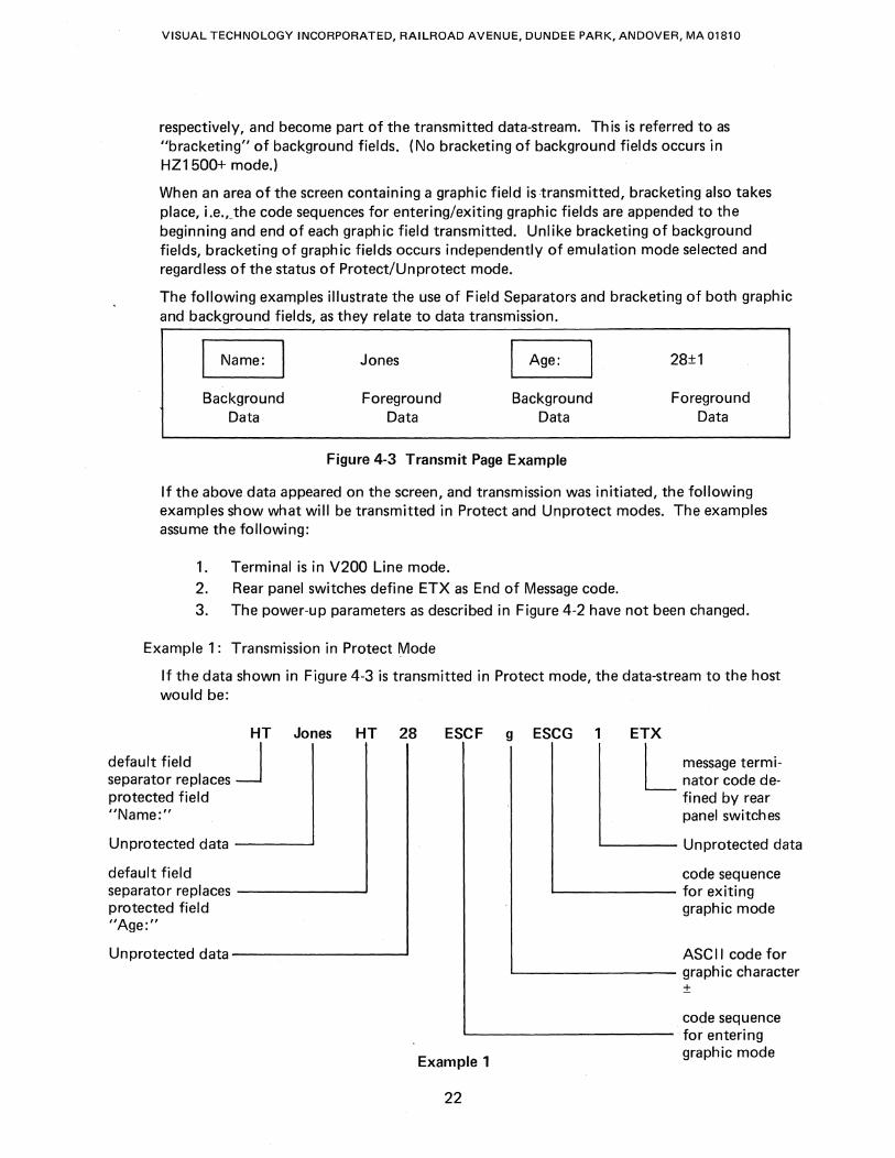
respectively, and become part of the transmitted data-stream. This is referred to as "bracketing" of background fields. (No bracketing of background fields occurs in HZ1500+ mode.)
When an area of the screen containing a graphic field is transmitted, bracketing also takes place, i.e.,_the code sequences for entering/exiting graphic fields are appended to the beginning and end of each graphic field transmitted. Unlike bracketing of background fields, bracketing of graphic fields occurs independently of emulation mode selected and regardless of the status of Protect/Unprotect mode.
The following examples illustrate the use of Field Separators and bracketing of both graphic and background fields, as they relate to data transmission.
Name:
Background Data
Jones
Foreground Data
I Age:
Background Data
Figure 4-3 Transmit Page Example
28±1
Foreground Data
If the above data appeared on the screen, and transmission was initiated, the following examples show what will be transmitted in Protect and Unprotect modes. The examples assume the following:
1. Terminal is in V200 Line mode.
2. Rear panel switches define ETX as End of Message code.
3. The power-up parameters as described in Figure 4-2 have not been changed.
Example 1: Transmission in Protect Mode
If the data shown in Figure 4-3 is transmitted in Protect mode, the data-stream to the host would be:
HT Jones HT 28
default field J separator replaces protected field "Name:"
Unprotected data -----'
default field separator replaces ------~ protected field "Age:"
Unprotected data -------------'
ESCF g ESCG 1 ETX
Example 1
22
L message terminator code defined by rear panel switches
L--____ Unprotected data
code sequence '-------- for exiting
graphic mode
ASCII code for L..-________ graphic character
±
code sequence for entering graphic mode

VISUAL TECHNOLOGY INCORPORATED, RAILROAD AVENUE, DUNDEE PARK, ANDOVER, MA 01810
Example 2: Transmission in Unprotect Mode
If the data shown in Figure 4-3 is transmitted in Unprotect mode, the data-stream to the host would be:
ESC4 Name: ESC3 Jones
COdesequencefor:J1 entering back-ground mode
background data
ESC4 Age: ESC3 28 ESCF g ESCG 1 ETX L: message terminator as defi ned by rear panel switches
foregrou nd data
code sequence for code sequence for exiting background _____ ---J '------ exiting graphic
mode mode
foreground data ----~------' L..-_____ ASCII code for graph ic character ±
code sequence for entering background mode
background data
Example 2
code sequence for L..-_______ entering graphic
mode
'----------- foreground data
code sequence for '------------- exiting background
mode
4.12_2.2 Data Compression
When transmitting a buffered message, the VISUAL 200 will automatically delete insignificant spaces depending on the emulation mode, and transmission mode selected.
The following descriptions of data compression apply to all emulation modes except when HZ1500+ and Batch modes are selected. In this case data compression is performed per a stored carriage return code, as described later in this section.
Line Mode_'
Page Mode:
Batch Mode_-
HZ 1500+, Batch Modes_-
Spaces to the right of the last character on the line are suppressed_ The End of Message code (s) if any, are immediately appended to the last character_
Spaces of the right of the last character on each line are suppressed, the End of Line code (s), if any, are appended to the last character of each line. Spaces to the right of the last character of the last line are suppressed, followed by the End of Message code (s), if any_
Data compression is the same as for Page mode, however, in this mode the "Iast" line is the line in which the cursor was located when transmission was initiated_ This "last" line mayor may not be the 24th line of the screen.
If HZ1500+ emulation mode is selected, no automatic data compression will occur when transmitting in Batch mode. Data compression in this case is accomplished by using a stored CR (carriage return) code. The stored CR code is displayed as a half-intensity solid rectangle (rub-out code) and marks the point where data compression is to begin on any particular line_ The stored CR code will be displayed whenever a CR code is received (keyboard or data-line) when not immediately preceeded by the lead-in code, tilde (~). When a CR code is received, the half-intensity
23

VISUAL TECHNOLOGY INCORPORATED, RAILROAD AVENUE, DUNDEE PARK, ANDOVER, MA 01810
rectangle is stored at the cursor location and the cursor advanced per the Auto CR/LF rear panel switch. When HZ1500+ mode and Line or Page Transmit mode are selected, data compression will be accomplished in a manner identical to the other emulation modes. In these cases the CR code will not be stored, and thus will not be used for data compression.
4.12.2.3 Line Mode Transmission
When Line Mode is set, and transmission is initiated, only the data on the line specified by the cursor will be transmitted. Data compression deletes spaces of the last field and only those spaces from the last character to the end of the line. The start of Message code, if any, is appended at the beginning of the transmitted line. Because the maximum length of transmitted data is one line, the End of Line code (s), if any, are not used and the transmission is terminated with the End of Message code (s).
When transmission ends, the cursor is placed at the left-hand margin of the next line. In HZ1500+ mode, the cursor is placed in the same column, one line below the transmitted line, except when the last line has been transmitted, when the cursor will be placed at the left margin.
NOTE
If the last line is transmitted while the terminal is in Unprotect mode and Scroll mode, the screen will scroll-up one line.
4.12.2.4 Page Mode Transmission
When Page mode is set, and transmission is initiated, all data on the screen will be transmitted. (If Protect mode is set, only the unprotected fields will be transmitted). Spaces to the right of the last character on each line are suppressed, just as in Line mode. The start of the Message code, if any, is appended to the beginning of the transmitted page. At the end of each line, the End of Line code (s) are appended. End of Message codes are appended for the last line.
4.12.2.5 Batch Mode Transmission
When Batch mode is set, and transmission is initiated, all data from the beginning of the line following the previous transmit symbol, up to, but not including the cursor location, will be transmitted. The transmit symbol is a full-intensity solid rectangle (rub-out) which is stored on the screen to mark the end of transmission. A new transmit symbol is stored at the end cursor location to mark the new last point of transmission and the cursor is advanced to the left-hand margin of the next line. If no transmit symbol was previously on the screen, the transmission will occur from the home position, up to, but not including the cu rsor location. The Start of Message, End of Line, and End of Message codes will be appended at the Start of Message, End of Lines and End of Message respectively provided the terminal is not set to HZ1500+ mode. In HZ1500+ Batch mode, the Start of Message code will not be appended and the only End of Line code is the stored CR code (if any), which is also used for data compression as described in section 4.12.2.2. The End of Message code is still initially determined by rear panel switches just as in any of the other emulation modes.
24

VISUAL TECHNOLOGY INCORPORATED, RAILROAD AVENUE, DUNDEE PARK, ANDOVER, MA 01810
4.12.3 Block Mode Commands
When the Block Mode Option is installed, extra commands and modes are provided. This section details these commands and modes and their effect on the terminal.
4.12.3.1 Set Block Mode Command
Code Sequences: "'# HZ1500+ mode ESC m All other modes
Block mode may be enabled via this command when received from the data-line or keyboard.
4.12.3.2 Reset Block Mode Command
Code Sequences: "'$ HZ1500+ Mode ESC n All other modes
Character mode may be enabled via this command when received from the data-line or the keyboard. All Block mode parameters will remain unchanged.
4.12.3.3 Lock Block Key Command
Code Sequences: ~; HZ1500+ mode ESC; All other modes
This command inhibits the operator from changing Block/Character mode by depressing the BL and CONVERT FUNCTION keys. The operator may change modes by using the Set/ Reset Block Mode command sequences through the keyboard.
4.12.3.4 Unlock Block Key Command
Code Sequences: ~: HZ1500+ mode ESC: All other modes
This command allows the operator to change between Block/Character modes by use of the CONVERT FUNCTION and BL keys.
4.12.3.5 Set Line Mode Command
Code Sequences: ~. HZ1500+ mode ESCo All other modes
This command conditions the terminal for Line mode transmission as described in section 4.12.2.3.
4.12.3.6 Set Page Mode Command
Code Sequences: '" ( HZ1500+ mode ESC 9 All other modes
This command conditions the terminal for Page mode transmission as described in section 4.12.2.4.
25

VISUAL TECHNOLOGY INCORPORATED, RAILROAD AVENUE, DUNDEE PARK, ANDOVER, MA 01810
4.12.3.7 Set Batch Mode Command
Code Sequences: '" % HZ1500+ mode ESC 8 All other modes
This command conditions the terminal for Batch mode transmission as described in section 4.12.2.5.
4.12.3.8 Set Protect Command
Code Sequences: '" + HZ 1500+ mode ESC 6 All other modes
This command causes all background data on the screen to be protected. See section 4.12.2.1 for a discussion of the Protect/Un protect mode.
4.12.3.9 Set Unprotect Command
Code Sequences: '" * HZ1500+ mode ESC 7 All other modes
This command causes all data on the screen, background and foreground, to be unprotected. See section 4.12.2.1 for a discussion of the Protect/Unprotect mode.
4.12.3.10 Set Auto-Tab Command
Code Sequences: '" 8 HZ1500+ mode ESC q All other modes
When Auto-Tab is set (allowed in Protect mode only) attempted keyboard data entry into a protected field results in the following events:
• The bell is sounded.
• The cursor is moved to the right and down to the first unprotected position.
• The keyboard character is entered at this unprotected position.
• The cursor is advanced one position.
4.12.3.11 Reset Auto-Tab Command
Code Sequences: '" 9 HZ 1500+ mode ESC S All other modes
When Auto-Tab is reset, attempted keyboard data entry into a protected field results in the following events.
• The bell is sounded.
• The cursor is not moved.
• The keyboard character is not entered on the screen.
26

VISUAL TECHNOLOGY INCORPORATED, RAILROAD AVENUE, DUNDEE PARK, ANDOVER, MA 01810
4.12.3.12 Set Field Separator Command
Code Sequences: '" 700 HZ1500+ mode ESC.00 All other modes
This command allows the user to select any ASCII character as the Field Separator code. When the terminal is initialized, the Field Separator code will assume it's default value as specified in Figure 4-2.
The above code sequence requires that the last two digits be in hexadecimal notation. For example, 09 selects the HT code as the Field Separator, 0E is SO, 1 B, is ESC. To delete the field separator completely, code 00 (Null) is used. When transmission is initiated, the Field Separator will be inserted into the data stream in lieu of the background (protected) fields, if the Protect mode is set. If the Unprotect mode is set, the backgrQund fields will be included in the transmitted data stream in lieu of the"Field Separator code, and will be bracketed with the enter/exit background code sequences.
NOTE
The Set Field Separator command is ignored in HZ1500+ Batch mode.
4.12.3.13 Set Start of Message Code
Code Sequences: '" N00HZ1500+ mode ESC N00 All other modes
This command allows user to select any ASCII character as the Start of Message code. The code will preceed any messages transmitted in Block Mode, except when the terminal is set to HZ1500+ Batch Mode. I n this case no Start of Message code is appended.
In a manner similar to the Set Field Separator command, this command requires that the last two digits of the code sequence be in hexadecimal notation. For example, 01 is SOH, 02 is STX, etcetera.
4.12.3.14 Set First End of Line Code
Code Sequences: '" 400 HZ1500+ mode ESC U00 All other modes
This command allows the user to select any ASCII character as the First End of Line code. When the terminal is initialized, the End of Line code assumes its default value (depending on emulation mode selected) as specified in Figure 4-2.
The First End of Line code is applicable in all modes except Line Mode Transmission (all emulations) and HZ1500+ Batch mode. When transmission is initiated, this code will be automatically appended at the end of lines.
When this command is received it automatically resets any Second End of Line code previously set.
In a manner similar to the Set Field Separator command, the Set First End of Line code command requires that the last two digits of the code sequence be in hexadecimal notation.
27

VISUAL TECHNOLOGY INCORPORATED, RAILROAD AVENUE, DUNDEE PARK, ANDOVER, MA 01810
4.12.3.15 Set Second End of Line Code
Code Sequences: ~ 600 HZ 1500+ mode ESC V00 All other modes
This command allows the user to select any ASCII character as the Second End of Line code. Like the First End of Line code, this code is applicable in all modes except Line Mode Transmission and HZ1500+ Batch mode.
When transmission is initiated, this code will be automatically appended following the First End of Line code.
Whenever the First End of Line code is changed the Second End of Line code is automatically deleted. It is therefore necessary to re-enter the Second End of Line code.
The above code sequence requires that the last two digits be in hexadecimal notation.
4.12.3.16 Set First End of Message Code
Code Sequences: ~ 300 HZ1500+ mode ESC, 00 All other modes
This command allows the user to select any ASCII character as the First End of Message code. When the terminal is initialized, the First End of Message code will be either ETX, EOT, or CR as determined by rear panel switches (left bank 5 and 6).
When this command is received, the Second End of Message code, if any, is reset. To delete the First End of Message code completely, code 00 (Null) is used.
The above code sequence requires that the last two digits be in hexadecimal notation.
4.12.3.17 Set Second End of Message Code
Code Sequences: ~ 000 HZ1500+ mode ESC 000 All other modes
This command allows the user to select any ASCII character as the Second End of Message code. This command must be repeated if the First End of Message code is changed.
As with the Set First End of Message code command, this command requires that the last two digits be in hexadecimal notation. To delete the Second End of Message code completely, code 00 (Null) is used.
4.12.3.18 Remote Transmit Command
Code Sequences: ~ SO, HZ1500+ mode ESC 5 All other modes
This command, when received while the terminal is in Block mode, will cause transmission to begin in a manner identical to the operator depressing the SEND key with the CONVERT FUNCTION key.
4.12.4 I nterrupted Transmission
While the VISUAL 200 is in the process of transmitting, it is possible for the host to inhibit transmission for an indefinite period of time.
28
VISUAL TECHNOLOGY INCORPORATED, RAILROAD AVENUE, DUNDEE PARK, ANDOVER, MA 01810
If the host sends the VISUAL 200 an XOFF (DC3) in full duplex, the VISUAL 200 will suspend transmission. Up to two characters may be transmitted after receipt of the XOFF before transmission halts. When the host sends an XON (DC1), transmission will resume at the point where it halted. Transmission is also halted whenever the CONVERT FUNCTION and RST keys are depressed simultaneously.
4.12.5 Tab Stops
When operating in Block mode and Unprotected mode, tab functionality will be as described in section 4.3.
In Protect mode, columnar tab stops will not be recognized. The only tab stops will be the beginning of unprotected fields.
4.12.6 Parity Errors
In Block mode, detected parity errors are displayed as PE as in Character mode. The originally received code with the parity error is not retained in internal memory, rather a Rubout (DE L) code is used. If the area of the screen containing the parity error is subsequently transmitted the following sequence will be transmitted when the PE is encountered:
Batch mode, HZ1500+ ............................. . Batch mode, all other modes ........................ . Page and Line mode, HZ1500+ ...................... . Page and Line mode, all other modes .................. .
4.12.7 Programmable Function Keys
4.12.7.1 General
~F DEL ~G ESC F DEL ESC G ~F ~G
ESC F ESC G
When the Block Mode Option is installed, a row of 14 Programmable Function keys (F0 through F 13) is provided as standard. When depressed, each key will generate a pre-defined sequence, just as in character mode, if not programmed otherwise. The pre-defined sequence for each key is illustrated in Figure 3-3.
Each key may be programmed to generate a user-defined sequence when depressed. This sequence may be a maximum of 48 characters long. When this boundry is reached while programming, the bell will sound and the terminal will exit the program mode.
A function key may be downline loaded from the host or loaded from the keyboard via Escape Sequence and may contain displayable codes, control codes, and Escape Sequences. Once a key has been programmed, it will remain programmed until the terminal is reinitialized. Changing between Block/Character mode will not alter the information programmed into the function keys.
Each key may be programmed so that its message is sent to the screen, the host or part of the message to each destination.
Function keys may be strung together by loading a "call" for one function key into another function key. When linking keys, the maximum number of characters which can be transmitted by depressing a single key is 255. If keys are linked which exceed this maximum, transmission will be terminated and the terminal will return to normal operation. CAUTION: No check is made for an indefinite loop!
29
VISUAL TECHNOLOGY INCORPORATED, RAILROAD AVENUE, DUNDEE PARK, ANDOVER, MA 01810
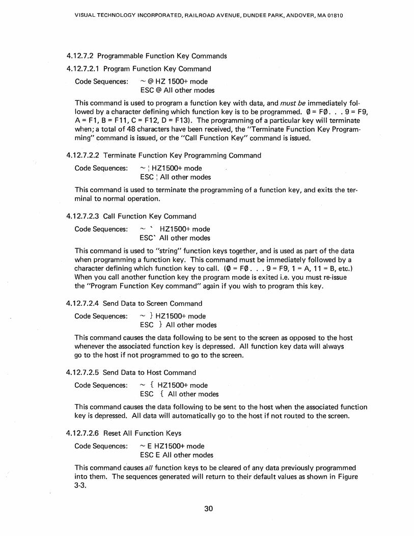
4.12.7.2 Programmable Fu nction Key Commands
4.12.7.2.1 Program Function Key Command
Code Sequences: '" @ HZ 1500+ mode ESC @ All other modes
This command is used to program a function key with data, and must be immediately followed by a character defining which function key is to be programmed. 0 = F0 ... 9 = F9, A = F1, B = F11, C = F12, D = F13). The programming of a particular key will terminate when; a total of 48 characters have been received, the "Terminate Function Key Programming" command is issued, or the "Call Function Key" command is issued.
4.12.7.2.2 Terminate Function Key Programming Command
Code Sequences: '" : HZ1500+ mode ESC: All other modes
This command is used to terminate the programming of a function key, and exits the terminal to normal operation.
4.12.7.2.3 Call Function Key Command
Code Sequences: ",' HZ1500+ mode ESC' All other modes
This command is used to "string" function keys together, and is used as part of the data when programming a function key. This command must be immediately followed by a character defining which function key to call. (0 = F0 ... 9= F9, 1 = A, 11 = B, etc.) When you call another function key the program mode is exited i.e. you must re-issue the "Program Function Key command" again if you wish to program this key.
4.12.7.2.4 Send Data to Screen Command
Code Sequences: '" } HZ 1500+ mode ESC } All other modes
This command causes the data following to be sent to the screen as opposed to the host whenever the associated function key is depressed. All function key data will always go to the host if not programmed to go to the screen.
4.12.7.2.5 Send Data to Host Command
Code Sequences: '" { HZ1500+ mode ESC {All other modes
This command causes the data following to be sent to the host when the associated function key is depressed. All data will automatically go to the host if not routed to the screen.
4.12.7.2.6 Reset All Function Keys
Code Sequences: '" E HZ1500+ mode ESC E All other modes
This command causes al/ function keys to be cleared of any data previously programmed into them. The sequences generated will return to their default values as shown in Figure 3-3.
30
VISUAL TECHNOLOGY INCORPORATED, RAILROAD AVENUE, DUNDEE PARK, ANDOVER, MA 01810
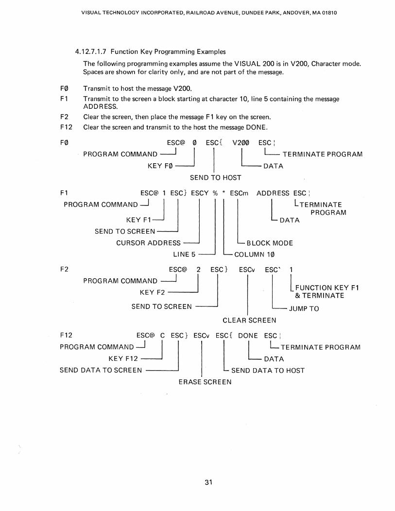
4.12.7.1.7 Function Key Programming Examples
The following programming examples assume the VISUAL 200 is in V200, Character mode. Spaces are shown for clarity only, and are not part of the message.
F0 Transmit to host the message V200.
F 1 Transmit to the screen a block starting at character 10, line 5 containing the message ADDRESS.
F2 Clear the screen, then place the message F 1 key on the screen.
F12 Clear the screen and transmit to the host the message DONE.
F0 ESC@ 0 ESC{
PROGRAM COMMAND ~ I KEYF0~
V200 ESC:
L ~ TERMINATE PROGRAM
DATA
SEND TO HOST
F 1 ESC@ 1 ESC} ESCY % * ESCm ADDRESS ESC:
PROGRAM COMMAND ---.J ~I KEY F1
SEND TO SCREEN
CURSOR ADDRESS
LINE 5
L L TERMINATE PROGRAM
DATA
BLOCK MODE
COLUMN 10
F2 ESC@ 2 ESC} ESCv ESC' 1
PROGRAM COMMAND _I~ I KEYF2~
SEND TO SCREEN
L l FUNCTION KEY F1 & TERMINATE
JUMP TO
CLEAR SCREEN
F12 ESC@ C ESC} ESCv ESC{ DONE ESC:
PROGRAM COMMAND ---1 I I KEYF12
SEND DATA TO SCREEN
l L LTERMINATE PROGRAM
DATA
SEND DATA TO HOST
ERASE SCREEN
31


VISUAL TECHNOLOGY INCORPORATED, RAILROAD AVENUE, DUNDEE PARK, ANDOVER, MA 01810
5. INTERFACES
5.1 CODE
The VISUAL 200 terminal communicates using the ASCII 7 bit code format. Communications is in the start-stop asynchronous serial mode.
5.2 ASYNCHRONOUS DATA ,
Transmitted and received data is formatted into a 10 or an 11 bit word containing a start bit, 7 ASCII data bits, a parity bit and one or two stop bits. The start bit is always a spacing (zero) bit, followed by the 7 data bits with the least significant bit first. The single parity bit is next and can be odd, even, mark (always a one) or space (always a zero). Each character ends with a stop bit which has a mark polarity. At 110 baud the terminal selects two stop bits, and at all other speeds one stop bit is used.
Received data is monitored to detect parity errors and framing errors. If the terminal has Even parity selected and the received character parity is odd, or when Odd parity is selected and the received character is even a parity error symbol (p E) is displayed in place of the received character. Framing errors are detected by determining the number of stop bits received as compared to the number selected by the baud rate. Framing errors display as the parity error symbol.
5.3 FULL/HALF DUPLEX
5.3.1 Full Duplex
Full duplex communications imply that data can be transmitted and received in both directions simultaneously. The VISUAL 200 requires that full duplex operation utilize the same baud rate and parity in both directions.
5.3.2 Half Duplex
The VISUAL 200 operating in half duplex mode, can be used with half duplex modems such as the 202. Communications is in one direction at a time and must be at the same baud rate and parity in each direction. Upon striking the first key, the terminal is set to the transmit mode. Care should be exercised at this point as some modems can take up to a half second before allowing the transmission of this character, resulting in lost data. Waiting until the first character appears on the screen will eliminate the problem.
The end of transmission mode is determ ined by typing the turn-around code (ETX, EOT or CR). The terminal now enters the receive mode until the computer sends its message with the same turn-around code.
When the VISUAL 200 detects the computer's turn-around code, the terminal is automatically set to the transmit mode, thereby reducing the effect of the modem turn-around time.
The VISUAL 200 terminal has the capability of operating with a half duplex modem containing a secondary channel. When secondary channel is selected, turn-around is accomplished in the same manner in addition to the capability of selecting the direction. If the terminal is in the transmit mode and the computer wants to transmit, normal half duplex operation requires that the computer wait until the terminal sends the turn-around code and
33
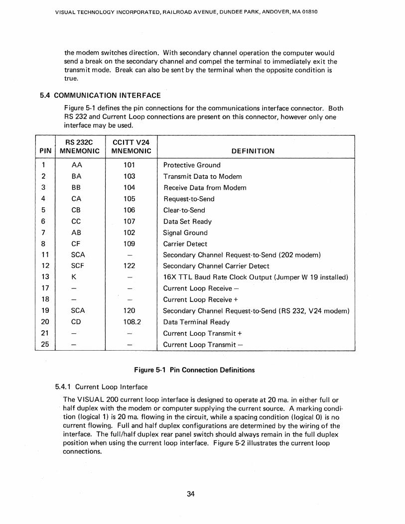
VISUAL TECHNOLOGY INCORPORATED, RAILROAD AVENUE, DUNDEE PARK, ANDOVER, MA 01810
the modem switches direction. With secondary channel operation the computer would send a break on the secondary channel and compel the terminal to immediately exit the transmit mode. Break can also be sent by the terminal when the opposite condition is true.
5.4 COMMUNICATION INTERFACE
PIN
1
2
3
4
5
6
7
8
11
12
13
17
18
19
20
21
25
Figure 5-1 defines the pin connections for the communications interface connector. Both RS 232 and Current Loop connections are present on this connector, however only one interface may be used.
RS 232C CCITT V24 MNEMONIC MNEMONIC DEFINITION
AA 101 Protective Ground
BA 103 Transmit Data to Modem
BB 104 Receive Data from Modem
CA 105 Request-to-Send
CB 106 Clear-to-Send
CC 107 Data Set Ready
AB 102 Signal Ground
CF 109 Carrier Detect
SCA - Secondary Channel Request-to-Send (202 modem)
SCF 122 Secondary Channel Carrier Detect
K - 16X TTL Baud Rate Clock Output (Jumper W 19 installed)
- - Current Loop Receive-
- - Current Loop Receive +
SCA 120 Secondary Channel Request-to-Send (RS 232, V24 modem)
CD 108.2 Data Termi'nal Ready
- - Current Loop Transmit +
- - Current Loop Transmit -
Figure 5-1 Pin Connection Definitions
5.4.1 Current Loop Interface
The VISUAL 200 current loop interface is designed to operate at 20 mao in either full or . half duplex with the modem or computer supplying the current source. A marking condi
tion (logical 1) is 20 mao flowing in the circuit, while a spacing condition (logical 0) is no current flowing. Full and half duplex configurations are determined by the wiring of the interface. The full/half duplex rear panel switch should always remain in the full duplex position when using the current loop interface. Figure 5-2 illustrates the current loop connections.
34

VISUAL TECHNOLOGY INCORPORATED, RAILROAD AVENUE, DUNDEE PARK, ANDOVER, MA 01810
FULL DUPLEX
+ 18 -.... f-------i+ I CU R RENT ~------. SOURCE. COMPUTER TRANSMITTER
-17-.~--------------------------------- +
_f------+~I CURRENTI-+21 ~ ~----------SOURCE COMPUTER RECEIVER
-25-~~------------------~-------------+
HALF DUPLEX
+ 18 -.. ----------+-11 CU R RENT ~------------. SOURCE. COMPUTER TRANSMITTER
-17~
+21 .----J c: COMPUTER RECEIVER
-25-~~-------------------------------+
Figure 5-2 Current Loop Connections
The current loop interface is limited to 50 volts (open Loop) and a minimum of 12 mao (closed loop).
5.4.2 Printer Interface
The VISUAL 200 printer interface is a unidirectional RS 232 interface, terminated in a 25 pin recepticle. A printer with an RS 232 interface and male connector which is designed to connect to a modem can be plugged directly into the printer connector without additional cables, adaptors, or modification. Figure 5-3 details the pin assignments and signals for the printer interface. The serial printer operates at the same baud rate and parity as the communications interface.
Pin Number Signal Name Definition
1 AA Protective Ground
3 BB Receive Data (to printer)
5 CB Clear to Send (always on)
6 CC Data Set Ready (always on)
7 AB Signal Ground
8 CF Carrier Detect (always on)
Figure 5-3 Visual 200 Printer Interface
35

VISUAL TECHNOLOGY INCORPORATED, RAILROAD AVENUE, DUNDEE PARK, ANDOVER, MA 01810
5.5 COMMUNICATIONS INTERFACE JUMPERS
5.5.1 General
There are four jumpers W3, W4, W5, and W6 which affect the pin and signal assignments on the communications interface. Normally the terminal is supplied with all four jumpers installed and in most cases no modifications are required.
5.5.2 Jumper Functions
W3, W4 connect the secondary channel Request-to-Send signal to pins 19 and 11 respectively. Using the current loop interface will allow both jumpers to remain. A modem which does not use either pin also will allow the jumpers to remain. When using an RS 232C half duplex modem, W4 should be removed. When using a 202 half duplex modem, W3 should be removed.
W5 and W6 are installed when the terminal is manufactured. They must be installed whenever the current loop interface is used. If the EIA interface is used and the modem utilizes pin 17, W5 must be removed. If the EIA interface is used and the modem utilizes pin 25, W6 must be removed.
W19 when installed, provides a 16 times TTL clock output to pin 13 of the communications interface. Should the modem use this pin W19 must be removed.
ooooooooooooc 000000000000
-c::::J-- -c::::J-W4 W3
0000000000000 00000<.-,000000
Figure 5-4 Interface Jumpers
36

\
VISUAL TECHNOLOGY INCORPORATED, RAILROAD AVENUE, DUNDEE PARK, ANDOVER, MA 01810
Terminal Type
Communication
Screen Presentation
Keyboard
Data Entry
Terminal Functions
Emulations
Audible Alarm
Operator Controls
6. SPECIFICATIONS
Code Type Speed
Method Mode Parity Interface
Display Unit
Display Format Character Type Refresh Rate Character Set
Roll Mode Page Mode
Cursor Remote Control
Functions:
Side Panel
Rear Panel
TTY compatible, Z-80 microprocessor based
128 Character ASCII Serial Asynchronous 110,200,300,1200,2400,4800,9600,19200 bps externally switch selectable Character by Character (Conversational) Full or Half Duplex Odd, Even, Mark, Space, Switch selectable EIA RS 232C or 20 Ma. Current Loop
12" non-glare CRT. Composite Video Output for use with external video monitor 24 lines X 80 characters; 1920 characters 7 X 9 Dot Matrix; 2 dot lower case descender 50 or 60 Hz. switch selectable 95 ASCII characters; upper/lower case plus 31 characters line drawing set
Detachable solid state typewriter keyboard, Type-o-matic repeat, numeric pad, optional function keys, caps lock
Bottom line with single line roll up Page overwrite
Non-destructive block Cursor; Left, Right, Up, Down, Home, Address; Up Scroll Erase: End of Line, Page or Field; Clear: Line, or Page: Tab; Back Tab; Insert Character; Delete Character; Set and Reset Columnar Tab; Enable/Disable Hold Screen; Set/Reset Print Copy; Set/Reset Print Only, Print Page; Set/Reset Background; Blink Line; Security Mode; Set/Reset Line Drawing; Read Cursor Address; Read Terminal Status
Hazeltine 1500+, Lear Siegler ADM-3A+, DEC VT -52+, ADDS 520+, externally switch selectable
On receipt of BE L code, and character entry in I nsert Character Mode
Power ON/OFF, High Intensity Brightness, Low Intensity Brightness, Power Circuit Breaker Reset Baud Rate, Parity, Emulation Mode, Page/Scroll, Half/Full Duplex, Turn-around Code, 50/60 Hz, Normal/Reverse Video, Auto New Line, CR New Line
37
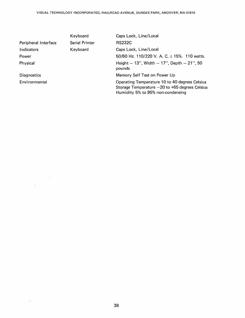
VISUAL TECHNOLOGY INCORPORATED, RAILROAD AVENUE, DUNDEE PARK, ANDOVER, MA 01810
Peripheral Interface
Indicators
Power
Physical
Diagnostics
E nvi ronmental
Keyboard
Serial Printer
Keyboard
Caps Lock, Line/Local
RS232C
Caps Lock, Line/Local
50/60 Hz. 110/220 V. A. C. ± 15%. 110 watts.
Height - 13", Width - 17", Depth - 21",50 pounds
Memory Self Test on Power Up
Operating Temperature 1 0 to 40 degrees Celsius Storage Temperature -20 to +65 degrees Celsius Humidity 5% to 95% non-condensing
38

VISUAL TECHNOLOGY INCORPORATED, RAILROAD AVENUE, DUNDEE PARK, ANDOVER, MA 01810
7. FIRST LEVEL MAINTENANCE
7.1 GENERAL
The VISUAL 200 terminal has been designedwith subassembly exchange as the prime mode of service. Fault isolation is provided in this section to identify the failing subassembly. Unless otherwise noted the power cord should be disconnected before disassembly of the terminal. Hazardous voltages may be present.
7.2 REAR PANEL
The removal of the rear panel will allow the removal of the logic printed circuit board, removal of the TV monitor printed circuit board, and access to the AC terminal block allowing rewiring from 110 volts to 220 volts.
7.2.1 Rear Panel Removal
Consult Figure 7-1 to locate the four screws which attach the rear panel to the top cover.
7.2.2 Rear Panel Installation
As indicated in Figure 7-1 loosely install the two painted flat head screws on the top of the rear panel first. Rotate the bottom of the panel into position and install and tighten the lower two black screws. Tighten the two top screws.
Figure 7-1 Rear Panel Screw Locations
39

VISUAL TECHNOLOGY INCORPORATED, RAILROAD AVENUE, DUNDEE PARK, ANDOVER, MA 01 8 10
7.3 TOP COVER
The top cover assembly consists of the top sheet metal cover and the front plastic bezel.
7.3.1 Top Cover Removal
First the rear panel must be removed per 7.2.1. Remove two screws from each side located at the bottom of the cover. Rotate the cover up from the rear while sliding the cover to the front as illustrated in Figure 7-2.
7.3.2 Top Cover Insta llation
The top cover is installed by sliding the cover to the rear of the terminal and lowering the cover as the bezel comes into contact with the face of the CRT. Insure that the lower edges of the cover on both sides are placed inside the base plate sides. Install two screws on each side and tighten.
7.4 PRINTED CIRCUIT BOARD REMOVAL AND INSTALLATION
Once the rear panel has been removed the printed circuit board is easily removed by unpluging two connectors and the removal of four cross head screws located near each of the PCB corners. The PCB is then rotated out at the top and lifted over the lower base edge. Installation is simply the reverse of the above steps.
7.3
Figure 7-2 Top Cover Removal
40
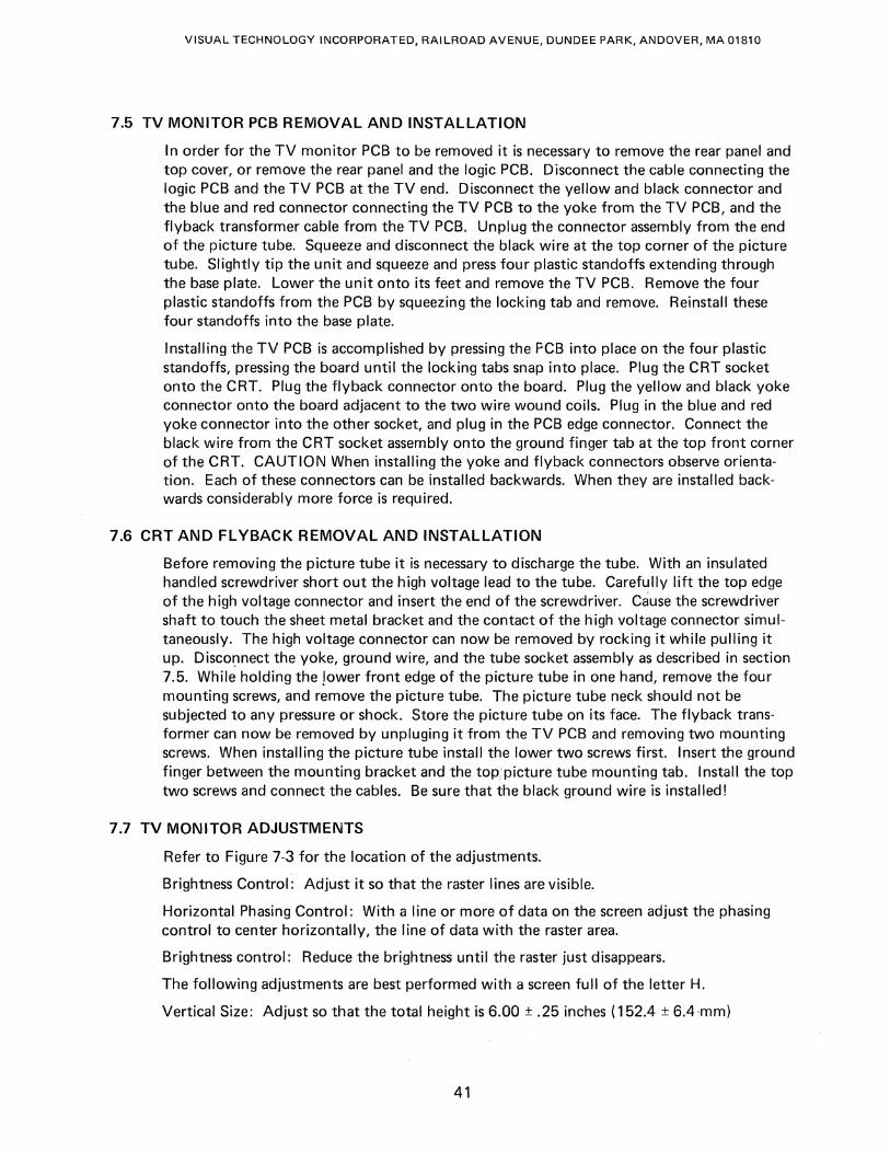
VISUAL TECHNOLOGY INCORPORATED, RAILROAD AVENUE, DUNDEE PARK, ANDOVER, MA 01810
7.5 TV MONITOR PCB REMOVAL AND INSTALLATION
In order for the TV monitor PCB to be removed it is necessary to remove the rear panel and top cover, or remove the rear panel and the logic PCB. Disconnect the cable connecting the logic PCB and the TV PCB at the TV end. Disconnect the yellow and black connector and the blue and red connector connecting the TV PCB to the yoke from the TV PCB, and the flyback transformer cable from the TV PCB. Unplug the connector assembly from the end of the picture tube. Squeeze and disconnect the black wire at the top corner of the picture tube. Slightly tip the unit and squeeze and press four plastic standoffs extending through the base plate. Lower the unit onto its feet and remove the TV PCB. Remove the four plastic standoffs from the PCB by squeezing the locking tab and remove. Reinstall these four standoffs into the base plate.
Installing the TV PCB is accomplished by pressing the PCB into place on the four plastic standoffs, pressing the board until the locking tabs snap into place. Plug the CRT socket onto the CRT. Plug the flyback connector onto the board. Plug the yellow and black yoke connector onto the board adjacent to the two wire wound coils. Plug in the blue and red yoke connector into the other socket, and plug in the PCB edge connector. Connect the black wire from the CRT socket assembly onto the ground finger tab at the top front corner of the CRT. CAUTION When installing the yoke and flyback connectors observe orientation. Each of these connectors can be installed backwards. When they are installed backwards considerably more force is required.
7.6 CRT AND FLYBACK REMOVAL AND INSTALLATION
Before removing the picture tube it is necessary to discharge the tube. With an insulated handled screwdriver short out the high voltage lead to the tube. Carefully lift the top edge of the high voltage connector and insert the end of the screwdriver. Cause the screwdriver shaft to touch the sheet metal bracket and the contact of the high voltage connector simultaneously. The high voltage connector can now be removed by rocking it while pulling it up. Disco':lnect the yoke, ground wire, and the tube socket assembly as described in section 7.5. While holding the lower front edge of the picture tube in one hand, remove the four mounting screws, and remove the picture tube. The picture tube neck should not be subjected to any pressure or shock. Store the picture tube on its face. The fly back transformer can now be removed by unpluging it from the TV PCB and removing two mounting screws. When installing the picture tube install the lower two screws first. Insert the ground finger between the mounting bracket and the topipicture tube mounting tab. Install the top two screws and connect the cables. Be sure that the black ground wire is installed!
7.7 TV MONITOR ADJUSTMENTS
Refer to Figure 7-3 for the location of the adjustments.
Brightness Control: Adjust it so that the raster lines are visible.
Horizontal Phasing Control: With a line or more of data on the screen adjust the phasing control to center horizontally, the line of data with the raster area.
Brightness control: Reduce the brightness until the raster just disappears.
The following adjustments are best performed with a screen full of the letter H.
Vertical Size: Adjust so that the total height is 6.00 ± .25 inches (152.4 ± 6.4 ·mm)
41
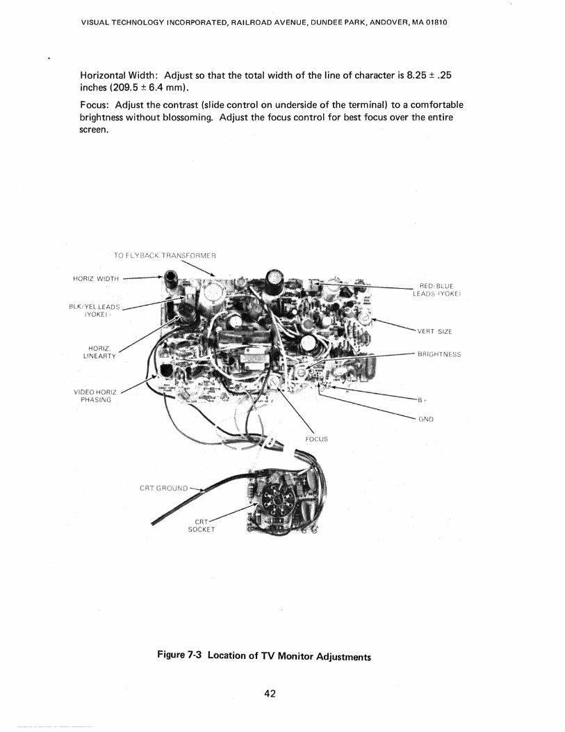
VISUAL TECHNOLOGY INCORPORATED, RAILROAD AVENUE, DUNDEE PARK, ANDOVER, MA 01810
Horizontal Width: Adjust so that the total width of the line of character is 8.25 ± .25 inches (209.5 ± 6.4 mm).
Focus: Adjust the contrast (slide control on underside of the terminal) to a comfortable brightness without blossoming. Adjust the focus control for best focus over the entire screen.
Figure 7-3 Location of TV Monitor Adjustments
42
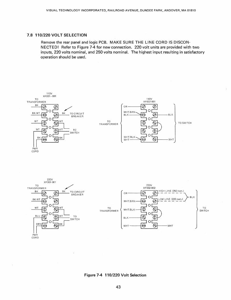
VISUAL TECHNOLOGY INCORPORATED. RAILROAD AVENUE. DUNDEE PARK. ANDOVER. MA 01810
7.8 110/220 VOLT SELECTION
Remove the rear panel and logic PCB. MAKE SURE THE LINE CORD IS DISCONNECTED! Refer to Figure 7-4 for new connection. 220 volt units are provided with two inputs, 220 volts nominal, and 250 volts nominal. The highest input resulting in satisfactory operation should be used.
110V XF001-001
TO TRANSFORMER
PWR CORD
220V XF001-00l
TO TRANSFORMER
PWR CORD
/ BK TO CI RCUIT
BREAKER
TO SWITCH
f--__ TO CIRCUIT BREAKER
TO SWITCH
110V XF002-001
OR
WHT/BRN 0 BLK BLK
0 TO
TO SWITCH TRANSFORMER
0
WHT/BLK 0
WHT WHT
220V XFOO2-002
HIGH LINE (250 nom.) OR ------}
BLK
WHT/BRN L~ ':::N~ (EO~O~)
0 TO
WHT/BLK TO
TRANS FORME R SWITCH 0
BLK
WHT WHT
Figure 7-4 110/220 Volt Selection
43

VISUAL TECHNOLOGY INCORPORATED, RAILROAD AVENUE, DUNDEE PARK, ANDOVER, MA 01810
7.9 TROUBLESHOOTING
7.9.1 Self Test
The VISUAL 200 contains a self test feature which is activated each time the terminal is turned on. When the terminal is turned on the Caps Only LED and the On LED are illuminated. The self test checks the RAM memory for failures and checks the program PROMs for validity using a check sum. Upon successful completion of these tests the Caps Only LED is extinguished and the cursor is di~played.
7.9.2 Fault Isolation
Operation
Turn On
Caps Only & On LEDs on
Self test complete
No cursor Bell sounds in local
No height
No width
Video tilted
Video size too small
Video jittering
Keyboard
No data
Fault
Caps Only & On LEDs not on
Caps Only doesn't extinguish
No Cursor
No Cursor
Horizontal line onTV
Vertical line onTV
Yoke adjustment
TV monitor
Wrong Frequency
No entry Caps LED on
Line or Local
Probable Cause,
Keyboard not plugged in Line cord not plugged in Circuit Breaker tripped Defective Logic PCB
Self test failure
Brightness set too low TV cable disconnected
Flyback disconnected CRT connector disconnected Defective TV PCB Defective Logic PCB
Yoke disconnected
Yoke disconnected
Yoke rotated from normal position
Yoke moved too far back Vert. size adjustment Horz. size adjustment
50/60 Hz. switch incorrect position
Terminal On Line Defective keyboard Defective Logic PCB
Keyboard disconnected Defective keyboard Defective Logic PCB FDX/HDX switch set wrong
44
Remedy
Plug in Plug in Reset Replace
Seat PROMs. Replace Logic PCB
Adjust Plug in
Plug in Plug in Replace Replace
Plug in yellowblack connector
Plug in blue-red connector
Adjust
Adjust
Adjust Adjust
Set**
Switch to Local Replace Replace
Plug in Replace Replace Set*

VISUAL TECHNOLOGY INCORPORATED, RAILROAD AVENUE, DUNDEE PARK, ANDOVER, MA 01810
Operation
On Line
On Line
On Line or Local
On Line
On Line
On Line or Local
Fault
Parity errors
Two characters for each key stroke
Wrong characters
EIA OK Current Loop doesn't work
Control Function not Recognized
Snapping sound
Probable Cause
Wrong Data Rate Wrong Parity Defective Logic PCB
FDX/HDX switch set to HDX
Defective keyboard Defective Logic PCB
Defective Logic PCB
Emulation switches Set to wrong position
CRT ground wire not connected (Black wire)
Remedy
Set* Set* Replace
Set to FDX*
Replace Replace
Replace
Set*
Connect
*indicates that after these switches are changed the operator must depress the Convert Function key simultaneously with the RST key or turn the terminal off and,then on in order for the new position to be recognized.
**indicates that the terminal must be turned off and then on in order for the 50/60 Hz switch to be recognized.
45

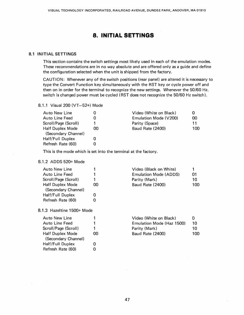
VISUAL TECHNOLOGY INCORPORATED, RAILROAD AVENUE, DUNDEE PARK, ANDOVER, MA 01810
8. INITIAL SETTINGS
8.1 INITIAL SETTINGS
This section contains the switch settings most likely used in each of the emulation modes. These recommendations are in no way absolute and are offered only as a guide and define the configuration selected when the unit is shipped from the factory.
CAUTION: Whenever any of the switch positions (rear panel) are altered it is necessary to type the Convert Function key simultaneously with the RST key or cycle power off and then on in order for the terminal to recognize the new settings. Whenever the 50/60 Hz. switch is changed power must be cycled (RST does not recognize the 50/60 Hz switch).
8.1.1 Visual 200 (VT -52+) Mode
Auto New Line Auto Line Feed Scroll/Page (Scroll) Half Duplex Mode
(Secondary Channel) Half/Full Duplex Refresh Rate (60)
o o 1 00
o o
Video (White on Black) Emulation Mode (V200) Parity (Space) Baud Rate (2400)
This is the mode which is set into the terminal at the factory.
8.1.2 ADDS 520+ Mode
Auto New Line 1 Video (Black on White) Auto Line Feed 1 Emulation Mode (ADDS) Scroll/Page (Scroll) 1 Parity (Mark) Half Duplex Mode 00 Baud Rate (2400)
(Secondary Channel) Half/Full Duplex 0 Refresh Rate (60) 0
8.1.3 Hazeltine 1500+ Mode
Auto New Line 1 Video (White on Black) Auto Line Feed 1 Emulation Mode (Haz 1500) Scroll/Page (Scroll) 1 Parity (Mark) Half Duplex Mode 00 Baud Rate (2400)
(Secondary Channel) Half/Full Duplex 0 Refresh Rate (60) 0
47
o 00 11 100
1 01 10 100
0 10 10 100

VISUAL TECHNOLOGY INCORPORATED, RAILROAD AVENUE, DUNDEE PARK, ANDOVER, MA 01810
8.1.4 ADM-3A+ Mode
Auto New Line Auto Line Feed* Scroll/Page (Scroll) Half Duplex Mode
(Secondary Channel) Half/Full Duplex Refresh Rate (60)
1 1 1 00
o o
Video (White on Black) 0 Emulation Mode (ADM-3A+) 11 Parity (Odd) 01
* I n ADM-3A+ mode the Au~' Line Feed switch is used for Space over Data. 1 = Space over Data. See section 3.1.2.9.
48

VISUAL TECHNOLOGY INCORPORATED, RAILROAD AVENUE, DUNDEE PARK, ANDOVER, MA 01810
APPENDIX I VISUAL 200 REMOTE COMMANDS
Visual 200
Function Lead in = ESC (C-[)
HOME * H CURSOR UP *A CURSOR DOWN * B CURSOR RIGHT *C CURSOR LEFT C-H, * D CURSOR UP-SCROLL * I CURSOR ADDRESS *Y, Row, Col TAB C-I BACK TAB *z SET TAB * 1 CLEAR TAB * 2 CLEAR ALL TABS * 9 SET FOREGROUND * 3 SET BACKGROUND *4 ERASE END OF FIELD * f ERASE END OF LINE * K ERASE END OF PAGE *J ERASE PAGE *w CLEAR LINE * t CLEAR PAGE * v CLEAR END OF PAGE-BKGND * u CLEAR END OF LINE * x CLEAR END OF PAGE * y
INSERT LINE I * L DELETE LINE *M DELETE CHARACTER *0 SET INSERT CHARACTER *i RESET INSERT CHARACTER * j
BLINK LINE * s SET SECURITY * a RESET SECURITY *b
SET HOLD SCREEN .1 * [ RESET HOLD SCREEN * \ LOCK KEYBOARD * h UNLOCK KEYBOARD * Q READ TERMINAL STATUS * e READ CURSOR ADDRESS * r SET GRAPHICS * F RESET GRAPHICS *G PRINT PAGE * 1 COpy ON */\ COpy OFF * -
TRANSPARENT ON *W TRANSPARENT & COpy OFF *X READ TERMINAL ID * Z SLOW SCROLL DISABLE * d SLOW SCROLL ENABLE * c SET PAD FUNCTION * = RESET PAD FUNCTION *> STOP BLINK *k VERTICAL CUR. ADDRESS NOT USED HORIZONTAL CUR. ADDRESS NOT USED
* = Lead in C-X = Control X Shaded Items are Functional in Block Mode Units ON L Y Commands Enclosed in boxes operate differently in Block Mode
ADDS 520+ Hazeltine 1500+ Lead in = ESC (C- [) Lead In = ~
C-A, * H *C-R
C-Z, * A *C-L
* B *C-K C-F, * C C-P, * C C-H, C-U, * D C-H, * D * I * I *Y, Row, Col *C-Q, Col, Row C-I C-I
* z * C-T * 1 * 1 * 2 * 2
* 9 * 9 * 3 * C--*4 * C-Y * f * f *K * K * J * J
*w * C-l * t * t C-L, *v * C-\ * u * C-W
* x * C-O *y * C-X
* L * C-Z *M * C-S *0 *0 *i *i * j * j
* s * s * a * a * b * b * [ * [
*\ *\ C-D, *h * C-U C-B, *Q * C-F * e * -* r * C-E * F * F *G *G * 1 * C-/\ C-R, * /\ * / C-T, * - * ? *W ~*~5 (Block Model
*X * ? * Z * Z * d *d * c * c * - * =
*> * > *k *k C-K, Row NOT USED C-P, Col. NOT USED
49
LSI ADM3A Lead in = ESC (C-!l
C-/\, * H C-K, * A * B C-L, * C C-H, * D * I *=, Row, Col C-I
* z * 1 * 2
* 9 * 3 *4 * f * K * J *w * t C-Z, *v * u
* x *y * L *M *0 *i * j
* s * a *b * [
*\ C-O, *h C-N, *Q * e * r * F *G * 1 */\ * -*W * X * Z * d * c
*< *> *k NOT USED NOT USED
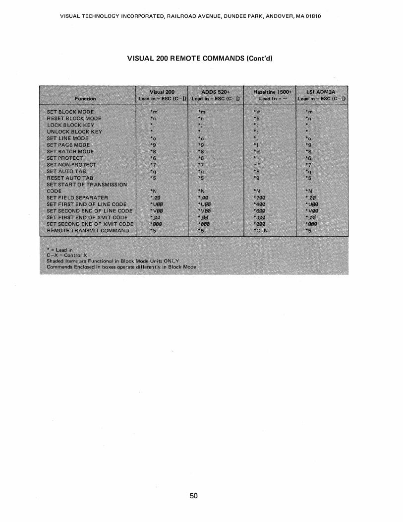
VISUAL TECHNOLOGY INCORPORATED, RAILROAD AVENUE, DUNDEE PARK, ANDOVER, MA 01810
VISUAL 200 REMOTE COMMANDS (Cont'd)
50

BIT
4
a a a a a 0
a a 1
1
1
1
1
1
1
1
VISUAL TECHNOLOGY INCORPORATED, RAILROAD AVENUE, DUNDEE PARK, ANDOVER, MA 01810
BIT BIT BIT
3 2 1
a a a a 0 1
a 1 0
a 1 1
1 a a 1 a 1
1 1 a 1 1 1
a a a 0 a 1
a 1 0
0 1 1
1 0 a 1 0 1
1 1 0
1 1 1
u.s. Character
$
@
[
\
1 {
I I
}
~
APPENDIX II ASCII CODE CHART
BIT 7 0 0 0
BIT 6 0 0 1
BIT5 0 1 0
~ 0 1 2
ROW
0 NUL DLE SP
1 SOH DCl !
2 STX DC2 "
3 ETX DC3 #
4 EOT DC4 $
5 ENQ NAK %
6 ACK SYN &
7 BEL ETB ,
8 BS CAN (
9 HT EM )
10 LF SUB *
11 VT ESC +
12 FF FS ,
13 CR GS -
14 SO RS . 15 SI US /
Swedish Norwegian Character Character
I:I $
@ @
Ii. A'=-
6 (/)
A A
a re
0 0
a a ~ ~
51
0 1 1 1 1
1 0 0 1 1
1 0 1 0 1
3 4 5 6 7
0 @ P p
1 A Q a q
2 B R b r
3 C S c s
4 D T d t
5 E U e u
6 F V f v
7 G W 9 w
8 H X h x
9 I Y i y
J Z j z
, K [ k [
< L \ I I I
= M 1 m }
> N 1\ n ~
? 0 -- 0 DEL
German Character
$
§
Ii.
6 0 a 0
a
i3

VISUAL TECHNOLOGY INCORPORATED, RAILROAD AVENUE, DUNDEE PARK, ANDOVER, MA 01810
Line Drawing Mode Symbol Codes
1 1 1 0 1 1
1 0 1
b4 b3 b2 bl 5 6 7
0 0 0 0 0 p ¥ 0 0 0 1 a q ¢
0 0 1 0 2 b + r £ 0 0 1 1 3 c --L s I
0 0 0 4 d T t
0 0 5 e L u
0 0 6 f 0 V
0 1 1 7 9 ± w
0 0 0 8 h -+ x
0 0 1 9 y
0 0 10 j z
0 1 1 11 k t {
1 0 0 12 I I
1 0 13 m -.J }
1 1 0 14 1\ Note 1 n I- Note 1
1 15 Space 0 ---4
Note 1: I n Hazeltine 1500+ mode carat becomes paragraph, in all other modes carat is space. Note: Shaded area character are subscripts
52

Dec. Value
0
2
3
4
5
6
7
8
9
10
11
12
13
14
15
16
17
18
19
20
21
22
23
24
25
26
27
28
29
VISUAL TECHNOLOGY INCORPORATED, RAILROAD AVENUE, DUNDEE PARK, ANDOVER, MA 01810
APPENDIX III CURSOR ADDRESS VALUES
VISUAL 200 (VT 52+), ADM 3A+ MODES
ASCII Key Coordinates Char. Stroke Col. No. (X)
NUL c@
SOH cA STX cB ETX Cc EOT cD ENQ cE ACK cF BEL cG BS BACKSPACE
HT ci LF LF
VT cK FF cL CR CR
SO cN SI Co DLE cp DC1 cQ DC2 cR DC3 Cs DC4 cT NAK Cu SYN Cv ETB Cw CAN Cx EM cY SUB Cz ESC ESC
FS c\
GS C]
53
Line No. (Y)
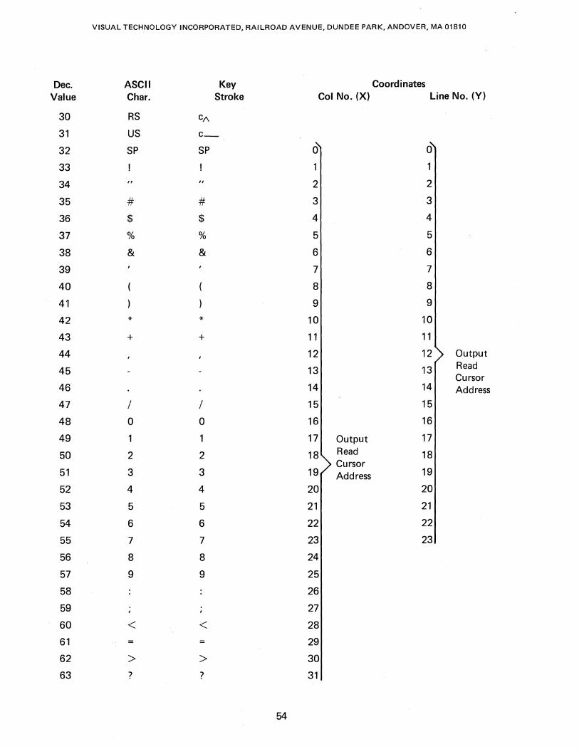
VISUAL TECHNOLOGY INCORPORATED, RAILROAD AVENUE, DUNDEE PARK, ANDOVER, MA 01810
Dec. ASCII Key Coordinates Value Char. Stroke Col No. (X) Line No. (Y)
30 RS c"
31 US c_
32 SP SP 0 0
33 1 1
34 " " 2 2
35 # # 3 3
36 $ $ 4 4
37 % % 5 5
38 & & 6 6
39 7 7
40 8 8
41 9 9
42 * * 10 10
43 + + 11 11
44 12 12 Output
45 13 13 Read Cursor
46 14 14 Address
47 / / 15 15
48 0 0 16 16
49 1 1 17 Output 17
50 2 2 18 Read 18 Cursor
51 3 3 19 Address 19
52 4 4 20 20
53 5 5 21 21
54 6 6 22 22
55 7 7 23 23
56 8 8 24
57 9 9 25
58 26
59 27
60 < < 28
61 = 29
62 > > 30
63 ? ? 31
54

VISUAL TECHNOLOGY INCORPORATED, RAILROAD AVENUE, DUNDEE PARK, ANDOVER, MA 01810
Dec. ASCII Key Coordinates Value Char. Stroke Col. No. (X) Line No. (Y)
64 @ @ 32
65 A A 33
66 B B 34 67 C C 35
68 0 0 36
69 E E 37 70 F F 38 71 G G 39 Output
72 H H 40 Read Cursor
73 I I 41 Address 74 J J 42
75 K K 43 76 L L 44
77 M M 45 78 N N 4!3 79 0 0 47
80 P P 48
81 Q Q 49 82 R R 50 83 S S 51 84 T T 52 85 U U 53 86 V V 54 87 W W 55 88 X X 56 89 y y 57 90 Z Z 58 91 59 92 \ \ 60 93 ] ] 61 94 1\ 1\ 62 95 63 96 64
55
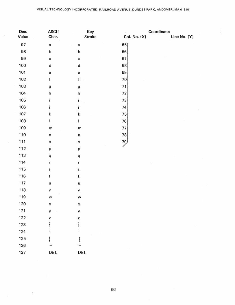
VISUAL TECHNOLOGY INCORPORATED, RAILROAD AVENUE, DUNDEE PARK, ANDOVER, MA 01810
Dec. ASCII Key Coordinates Value Char. Stroke Col. No. (X) Line No. (Y)
97 a a 65
98 b b 66
99 c c 67
100 d d 68
101 e e 69
102 f f 70
103 9 9 71
104 h h 72
105 73
106 j j 74
107 k k 75
108 I 76
109 m m 77
110 n n 78
111 0 0 79
112 p p
113 q q
114 r r
115 s s
116 t t
117 u u
118 v v
119 w w
120 x x
121 y y
122 z z
123 { 124
125
126
127 DEL DEL
56

Dec. Value
0
1
2
3
4
5
6
7
8
9
10
11
12
13
14
15
16
17
18
19
20
21
22
23
24
25
26
27
28
29
VISUAL TECHNOLOGY INCORPORATED, RAILROAD AVENUE, DUNDEE PARK, ANDOVER, MA 01810
ASCII Char.
NUL
SOH
STX
ETX
EaT
ENO
ACK
BEL
BS
HT
LF
VT
FF
CR
SO
SI
DLE
DC1
DC2
DC3
DC4
NAK
SYN
ETB
CAN
EM
SUB
ESC
FS
GS
c@
cA
cB
Cc cD
cE
cF
cG
APPENDIX IV CURSOR ADDRESS VALUES
ADDS 520+ MODE
Key Coordinates Stroke Col. No. (X) Line No. (V)
BACKSPACE
ci LF
cK
cL CR
cN
Co cp
Co cR
Cs cT
Cu Cv Cw Cx cy
Cz ESC
~ c]
57
Vertical Horizontal Position Position
0 0
1
2 2
3 3
4 4
5 5
6 6
7 7
8 8
9 9
10 0
11 0
12 0
13 0
14 0
15 0
16 10
17 11
18 12
19 13
20 14
21 15
22 16
23 17
8 18
9 19
10 10
11 10
12 10
13 10

VISUAL TECHNOLOGY INCORPORATED, RAILROAD AVENUE, DUNDEE PARK, ANDOVER, MA 01810
Dec. ASCII Key Coordinates Vertical Horizontal Value Char. Stroke Col. No. (X) Line No. (Y) Position Position
30 RS c/\ 14 10
31 US c_ 15 10
32 SP SP 0 0 0 20
33 1 1 21
34 " " 2 2 2 22
35 # # 3 3 3 23
36 $ $ 4 4 4 24
37 % % 5 5 5 25
38 & & 6 6 6 26
39 7 7 7 27
40 8 8 8 28
41 9 9 9 29
42 * * 10 10 10 20
43 + + 11 11 11 20
44 12 12 Output 12 20
43 13 13 Read 13 20
Cursor 46 14 14 Address 14 20
47 / / 15 15 15 20
48 0 0 16 16 16 30
49 1 17 Output 17 17 31
50 2 2 18 Read 18 18 32 Cursor
51 3 3 19 Address 19 19 33
52 4 4 20 20 20 34
53 5 5 21 21 21 35
54 6 6 22 22 22 36
55 7 7 23 23 23 37
56 8 8 24 8 38
57 9 9 25 9 39
58 26 10 30
59 27 11 30
60 < < 28 12 30
61 = 29 13 30
62 > > 30 14 30
63 ? ? 31 15 30 64 @ @ 32 0 40
58
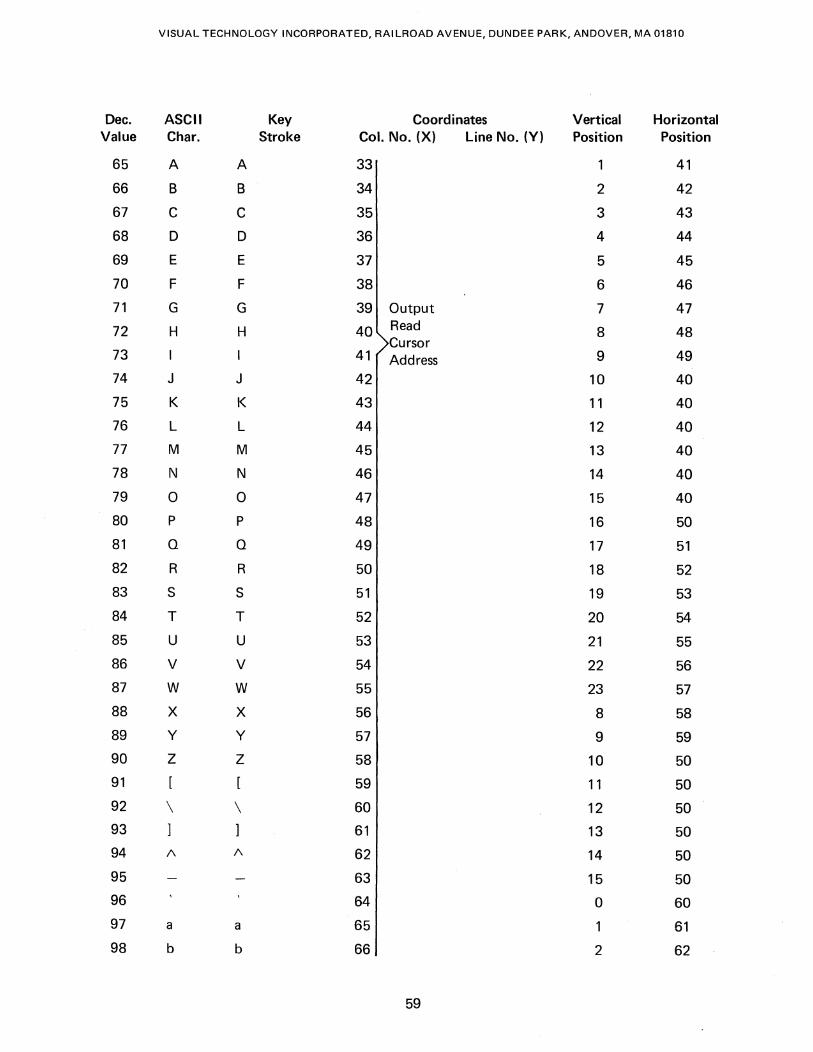
VISUAL TECHNOLOGY INCORPORATED, RAILROAD AVENUE, DUNDEE PARK, ANDOVER, MA 01810
Dec. ASCII Key Coordinates Vertical Horizontal Value Char. Stroke Col. No. (X) Line No. (Y) Position Position
65 A A 33 41
66 B B 34 2 42
67 C C 35 3 43
68 0 0 36 4 44
69 E E 37 5 45
70 F F 38 6 46
71 G G 39 Output 7 47
72 H H 40 Read Cursor
8 48
73 I I 41 Address 9 49
74 J J 42 10 40
75 K K 43 11 40
76 L L 44 12 40
77 M M 45 13 40
78 N N 46 14 40
79 0 0 47 15 40
80 P P 48 16 50
81 Q Q 49 17 51 82 R R 50 18 52 83 S S 51 19 53
84 T T 52 20 54
85 U U 53 21 55 86 V V 54 22 56 87 W W 55 23 57 88 X X 56 8 58 89 Y Y 57 9 59 90 Z Z 58 10 50 91 59 11 50 92 \ \ 60 12 50 93 ] ] 61 13 50 94 /\ /\ 62 14 50 95 63 15 50 96 64 0 60 97 a a 65 61 98 b b 66 2 62
59

VISUAL TECHNOLOGY INCORPORATED, RAILROAD AVENUE, DUNDEE PARK, ANDOVER, MA 01810
Dec. ASCII Key Coordinates Vertical Horizontal Value Char. Stroke Col. No. (X) Line No. (V) Position Position
99 c c 67 3 63
100 d d 68 4 64
101 e e 69 5 65
102 f f 70 6 66
103 9 9 71 7 67
104 h h 72 8 68
105 73 9 69
106 j j 74 10 60
107 k k 75 11 60
108 76 12 ; 60
109 m m 77 13 60
110 n n 78 14 60
111 0 0 79 15 60
112 p p 16 70
113 q q 17 71
114 r r 18 72
115 s s 19 73
116 t t 20 74
117 u u 21 75
118 v v 22 76
119 w w 23 77
120 x x 8 78
121 y y 9 79
122 z z 10 70
123 { { 11 70
124 12 70
125 } } 13 70
126 14 70
127 DEL DEL 15 70
60
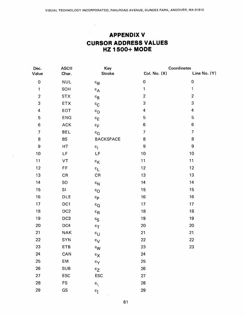
Dec. Value
0
1
2
3
4
5
6
7
8
9
10
11
12
13
14
15
16
17
18
19
20
21
22
23
24
25
26
27
28
29
VISUAL TECHNOLOGY INCORPORATED, RAILROAD AVENUE, DUNDEE PARK, ANDOVER, MA 01810
ASCII Char.
NUL
SOH
STX
ETX
EaT
ENO
ACK
BEL
BS
HT
LF
VT
FF
CR
so SI
DLE
DC1
DC2
DC3
DC4
NAK
SYN
ETB
CAN
EM
SUB
ESC
FS
GS
APPENDIX V CURSOR ADDRESS VALUES
HZ 1500+ MODE
Key Stroke Col. No. (X)
c@ 0
cA 1
cB 2
Cc 3
cD 4
cE 5
cF 6
cG 7
BACKSPACE 8
ci 9
LF 10
cK 11
cL 12
CR 13
cN 14
Co 15
cp 16
Co 17
cR 18
Cs 19
cT 20
Cu 21
Cv 22
Cw 23
Cx 24
cY 25
Cz 26
ESC 27
c\ 28
C] 29
61
Coordinates Line No. (Y)
0
1
2
3
4
5
6
7
8
9
10
11
12
13
14
15
16
17
18
19
20
21
22
23

VISUAL TECHNOLOGY INCORPORATED, RAILROAD AVENUE, DUNDEE PARK, ANDOVER, MA 01810
Dec. ASCII Key Coordinates Value Char. Stroke Col. No. (X) Line No. (Y)
30 RS CI\
31 US c_
32 SP SP 32 0
33 33 1
34 " 34 2
35 # # 35 3
36 $ $ 36 4
37 % % 37 5
38 & & 38 6
39 39 7
40 40 8
41 41 9
42 * * 42 10
43 + + 43 11
44 44 12
45 45 13
46 46 14
47 I I 47 15
48 0 0 48 16
49 1 1 49 Output 17
50 2 2 50 Read 18 Cursor
51 3 3 51 Address 19
52 4 4 52 20
53 5 5 53 21
54 6 6 54 22
55 7 7 55 23
56 8 8 56
57 9 9 57
58 58
59 59
60 < < 60
61 61
62 > > 62
63 ? ? 63
64 @ @ 64 0
62

VISUAL TECHNOLOGY INCORPORATED, RAILROAD AVENUE, DUNDEE PARK, ANDOVER, MA 01810
Dec. ASCII Key Coordinates Value Char. Stroke Col. No. (X) Line No. (Y)
65 A A 65 1
66 B B 66 2
67 C C 67 3
68 D D 68 4
69 E E 69 5
70 F F 70 6
71 G G 71 Output 7
72 H H 72 Read Cursor
8
73 I 73 Address 9
74 J J 74 10
75 K K 75 11
76 L L 76 12
77 M M 77 13
78 N N 78 14
79 0 0 79 15
80 p P 16
81 Q Q 17
82 R R 18
83 S S 19
84 T T 20
85 U U 21
86 V V 22
87 W W 23
88 X X
89 y y
90 Z Z
91
92 \ \ 93 ] ]
94 A A
95
96 j ~ 97 a a
98 b b
63

VISUAL TECHNOLOGY INCORPORATED, RAILROAD AVENUE, DUNDEE PARK, ANDOVER, MA 01810
Dec. ASCII Key Coordinates Value Char. Stroke Col. No. (X) Line No. (Y)
99 C c 3 3
100 d d 4 4
101 e e 5 5
102 f f 6 6
103 9 9 7 7
104 h h 8 8
105 9 9
106 j j 10 10
107 k k 11 11
108 12 12
109 m m 13 13
110 n n 14 14
111 0 0 15 Output 15 Output
112 p p 16 Read 16 Read Cursor Cursor
113 q q 17 Address 17 Address
114 r r 18 18
115 s s 19 19
116 t t 20 20
117 u u 21 21
118 v v 22 22
119 w w 23 23
120 x x 24
121 y y 25
122 z z 26
123 { 27
124 28
125 } 29
126 30
127 DEL DEL 31
64
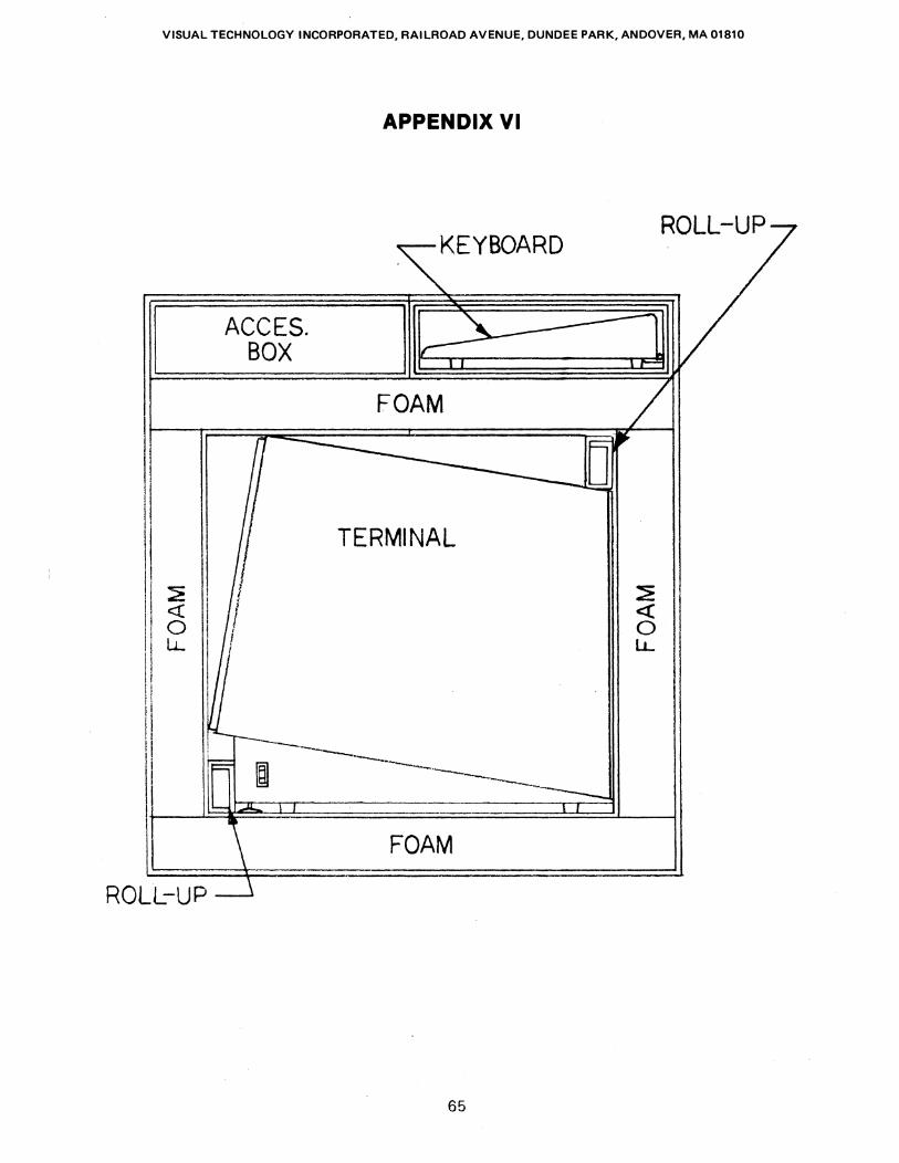
VISUAL TECHNOLOGY INCORPORATED, RAILROAD AVENUE, DUNDEE PARK, ANDOVER, MA 01810
APPENDIX VI
KEYBOARD
ACCES. BOX
FOAM
TERMINAL
----------FOAM
65

UM-200-001-0C
March,1980