videojet x10: manual (english) - bosch...
TRANSCRIPT
VideoJet X10Network Video Server
en Installation and Operating Manual

VideoJet X10
VideoJet X10 Table of Contents | en 3
Table of Contents
1 Preface 71.1 About this Manual 71.2 Conventions in this Manual 71.3 Intended Use 71.4 EU Directives 81.5 Rating Plate 8
2 Safety Information 92.1 Electric Shock Hazard 92.2 Installation and Operation 92.3 Maintenance and Repair 9
3 Product Description 113.1 Scope of Delivery 113.2 System Requirements 123.3 Overview of Functions 133.4 Connections on the Front Panel 163.5 Connections on the Rear Panel 17
4 Installation 194.1 Preparations 194.2 Mounting 194.3 Connections 204.4 Power On/Power Off 254.5 Setup Using the Configuration Manager 25
5 Configuration Using a Web Browser 275.1 Connecting 275.2 Configuration Menu 295.3 Basic Mode: Unit Access 315.4 Basic Mode: Date/Time 325.5 Basic Mode: Network 335.6 Basic Mode: Encoder Profile 345.7 Basic Mode: Audio 355.8 Basic Mode: Recording 365.9 Basic Mode: System Overview 365.10 Advanced Mode: Identification 375.11 Advanced Mode: Password 385.12 Advanced Mode: Date/Time 395.13 Advanced Mode: Display Stamping 405.14 Advanced Mode: Appearance 415.15 Advanced Mode: LIVEPAGE Functions 435.16 Advanced Mode: Logging 445.17 Advanced Mode: Video Input 455.18 Advanced Mode: Picture Settings 45
Bosch Security Systems Installation and Operating Manual DOC | V4.0 | 2009.06
4 en | Table of Contents VideoJet X10
5.19 Advanced Mode: Encoder Profile 475.20 Advanced Mode: Audio 505.21 Advanced Mode: Storage Management 515.22 Advanced Mode: Remote Video Device 535.23 Advanced Mode: Recording Profiles 545.24 Advanced Mode: Retention Time 565.25 Advanced Mode: Recording Scheduler 575.26 Advanced Mode: Recording Status 595.27 Advanced Mode: Alarm Connections 595.28 Advanced Mode: VCA 625.29 Advanced Mode: VCA Profiles 635.30 Advanced Mode: VCA Scheduled 675.31 Advanced Mode: VCA Event Triggered 695.32 Advanced Mode: Audio Alarm 705.33 Advanced Mode: Alarm E-Mail 715.34 Advanced Mode: Alarm Task Editor 735.35 Advanced Mode: Alarm Inputs 745.36 Advanced Mode: Relay 745.37 Advanced Mode: COM1 765.38 Advanced Mode: Network 775.39 Advanced Mode: Advanced 805.40 Advanced Mode: Multicasting 815.41 Advanced Mode: JPEG Posting 835.42 Advanced Mode: Encryption 845.43 Advanced Mode: Maintenance 845.44 Advanced Mode: Licenses 865.45 Advanced Mode: System Overview 865.46 Function Test 87
6 Operation 896.1 Operation with Microsoft Internet Explorer 896.2 The LIVEPAGE 916.3 Saving Snapshots 946.4 Recording Video Sequences 946.5 Running Recording Program 946.6 The RECORDINGS Page 956.7 Installing the Player 976.8 Hardware Connections Between Video Servers 986.9 Operation Using Software Decoders 100
7 Maintenance and Upgrades 1017.1 Testing the Network Connection 1017.2 Unit Reset 1017.3 Repairs 1027.4 Transfer and Disposal 102
8 Appendix 1038.1 Troubleshooting 1038.2 General Malfunctions 104
DOC | V4.0 | 2009.06 Installation and Operating Manual Bosch Security Systems

VideoJet X10 Table of Contents | en 5
8.3 Malfunctions with iSCSI Connections 1068.4 LEDs 1078.5 Processor Load 1088.6 Network Connection 1088.7 Serial Interface 1088.8 Terminal Block 1098.9 Communication with Terminal Program 1108.10 Copyrights 112
9 Specifications 1139.1 Unit 1139.2 Protocols/Standards 114
10 Glossary 115
11 Index 119
Bosch Security Systems Installation and Operating Manual DOC | V4.0 | 2009.06
6 en | Table of Contents VideoJet X10
DOC | V4.0 | 2009.06 Installation and Operating Manual Bosch Security Systems
VideoJet X10 Preface | en 7
1 Preface
1.1 About this ManualThis manual is intended for persons responsible for the installation and operation of the VideoJet X10. International, national and any regional electrical engineering regulations must be followed at all times. Relevant knowledge of network technology is required. The manual describes the installation and operation of the unit.
1.2 Conventions in this ManualIn this manual, the following symbols and notations are used to draw attention to special situations:
1.3 Intended UseThe VideoJet X10 network video server transfers video, audio and control signals over data networks (Ethernet LAN, Internet). There are various memory options for recording the images captured by the connected camera. The unit is intended for use with CCTV systems. Various functions can be triggered automatically by incorporating external alarm sensors. Other applications are not permitted.In the event of questions concerning the use of the unit which are not answered in this manual, please contact your sales partner or:Bosch Security SystemsRobert-Koch-Straße 10085521 OttobrunnGermanywww.boschsecurity.com
!CAUTION! This symbol indicates that failure to follow the safety instructions described may endanger persons and cause damage to the unit or other equipment.It is associated with immediate, direct hazards.
iNOTICE! This symbol refers to features and indicates tips and information for easier, more convenient use of the unit.
Bosch Security Systems Installation and Operating Manual DOC | V4.0 | 2009.06
8 en | Preface VideoJet X10
1.4 EU DirectivesThe VideoJet X10 network video server complies with the requirements of EU Directives 89/336 (Electromagnetic Compatibility) and 73/23, amended by 93/68 (Low Voltage Directive).
1.5 Rating PlateFor exact identification, the model name and serial number are inscribed on the bottom of the housing. Please make a note of this information before installation, if necessary, so as to have it to hand in case of questions or when ordering spare parts.
DOC | V4.0 | 2009.06 Installation and Operating Manual Bosch Security Systems

VideoJet X10 Safety Information | en 9
2 Safety Information
2.1 Electric Shock Hazard– Never attempt to connect the unit to any power network other than the type for which it
is intended.– Use only power supply units with UL approval and a power output according to LPS or
NEC Class 2.– Never open the housing.– Never open the housing of the power supply unit.– If a fault occurs, disconnect the power supply unit from the power supply and from all
other units.– Install the power supply and the unit only in a dry, weather-protected location.– If safe operation of the unit cannot be ensured, remove it from service and secure it to
prevent unauthorized operation. In such cases, have the unit checked by Bosch Security Systems.Safe operation is no longer possible in the following cases:
– if there is visible damage to the unit or power cables,– if the unit no longer operates correctly,– if the unit has been exposed to rain or moisture,– if foreign bodies have penetrated the unit,– after long storage under adverse conditions, or – after exposure to extreme stress in transit.
2.2 Installation and Operation– The relevant electrical engineering regulations and guidelines must be complied with at
all times during installation.– Relevant knowledge of network technology is required to install the unit.– Before installing or operating the unit, make sure you have read and understood the
documentation for the other equipment connected to it, such as cameras. The documentation contains important safety instructions and information about permitted uses.
– Perform only the installation and operation steps described in this manual. Any other actions may lead to personal injury, damage to property or damage to the equipment.
2.3 Maintenance and Repair– Never open the housing of the VideoJet X10. The unit does not contain any user-
serviceable parts. – Never open the housing of the power supply unit. The power supply unit does not contain
any user-serviceable parts.– Ensure that all maintenance or repair work is carried out only by qualified personnel
(electrical engineers or network technology specialists).
Bosch Security Systems Installation and Operating Manual DOC | V4.0 | 2009.06

10 en | Safety Information VideoJet X10
DOC | V4.0 | 2009.06 Installation and Operating Manual Bosch Security Systems

VideoJet X10 Product Description | en 11
3 Product Description
3.1 Scope of Delivery– VideoJet X10 network video server (with or without integrated hard drive)– 4 terminal blocks– Drilling template– Quick Installation Guide– Product CD with the following content:
– Quick Installation Guide– Manual– System Requirements document– Further documentation on Bosch Security Systems products– Configuration Manager– MPEG ActiveX control– Player and Archive Player– DirectX control– Microsoft Internet Explorer– Sun JVM– Adobe Acrobat Reader
iNOTICE! Check that the delivery is complete and in perfect condition. Arrange for the unit to be checked by Bosch Security Systems if you find any damage.
Bosch Security Systems Installation and Operating Manual DOC | V4.0 | 2009.06
12 en | Product Description VideoJet X10
3.2 System RequirementsGeneral Requirements– Computer with Windows XP or Windows Vista operating system– Network access (Intranet or Internet)– Screen resolution 1,024 × 768 pixels– 16- or 32-bit color depth– Installed Sun JVM
Additional Configuration Requirements– Microsoft Internet Explorer (version 6.0 or higher)
or
– Installed Configuration Manager program (version 2.0 or higher)
Additional Operational Requirements– Microsoft Internet Explorer (version 6.0 or higher)
or
– Receiver software, for example VIDOS (version 3.11 or higher) or Bosch Video Management System (version 2.02 or higher)or
– MPEG-4 compatible hardware decoder from Bosch Security Systems (for example VIP XD) as a receiver and connected video monitor
– For playing back recordings: connection to storage medium
i
NOTICE! Also note the information in the System Requirements document on the product CD supplied. If necessary, you can install the required programs and controls from the product CD supplied (see Section 3.1 Scope of Delivery, page 11).The Web browser must be configured to enable Cookies to be set from the IP address of the unit.In Windows Vista, deactivate protected mode on the Security tab under Internet Options.You can find notes on using Microsoft Internet Explorer in the online Help in Internet Explorer.
DOC | V4.0 | 2009.06 Installation and Operating Manual Bosch Security Systems
VideoJet X10 Product Description | en 13
3.3 Overview of FunctionsNetwork Video ServerThe VideoJet X10 is a compact network video server for a connected video source. It is primarily designed for encoding video, audio and control data for transfer over an IP network. With its encoding in the MPEG-4 format, the VideoJet X10 is ideally suited for making existing analog CCTV cameras IP-compatible and for remote access to digital VCRs and multiplexers.The use of existing networks means that integration with CCTV systems or local networks can be achieved quickly and easily.Two units, for example a VideoJet X10 as a sender and a VIP XD as a receiver, can create a standalone system for data transfer without a PC. Video images from a single sender can be received simultaneously on multiple receivers. Audio signals can also be transmitted from and to compatible units.The VideoJet X10 features industrial standard, robust equipment and is therefore equally suited to stationary as well as mobile use in rail or other vehicles.
ReceiverCompatible MPEG-4 enabled hardware decoders (for example the VIP XD) can be used as receivers. Computers with decoding software such as VIDOS or computers with the Microsoft Internet Explorer Web browser can also be used as receivers.
Video EncodingThe VideoJet X10 uses the MPEG-4 and H.264 video compression standards. Thanks to efficient encoding, the data rate remains low even with high image quality and can also be adapted to local conditions within wide limits.
Dual StreamingDual Streaming allows the incoming data stream to be encoded simultaneously according to two different, individually customized profiles. This feature creates two data streams that can serve different purposes, for example one for recording and one optimized for live transmission over the LAN.
MulticastIn suitably configured networks, the multicast function enables simultaneous real-time video transmission to multiple receivers. The UDP and IGMP V2 protocols must be implemented on the network for this function.
EncryptionThe VideoJet X10 offers a variety of options for protection against unauthorized reading. Web browser connections can be protected using HTTPS. You can protect the control channels via the SSL encryption protocol. With an additional license, the user data itself can be encrypted.
Bosch Security Systems Installation and Operating Manual DOC | V4.0 | 2009.06

14 en | Product Description VideoJet X10
Remote ControlFor remote control of external units such as pan or tilt heads for cameras or motorized zoom lenses, control data is transmitted via the VideoJet X10's bidirectional serial interface. This interface can also be used to transmit transparent data.
Tamper Detection and Motion DetectorsThe VideoJet X10 offers a wide range of configuration options for alarm signaling in the event of tampering with the connected camera. An algorithm for detecting movement in the video image is also part of the scope of delivery and can optionally be extended to include special video analysis algorithms.
SnapshotsIndividual video frames (snapshots) can be called up as JPEG images by the VideoJet X10, stored on the computer's hard drive or displayed in a separate browser window.
RecordingsVarious local memory options enable the VideoJet X10 to be used as a digital VCR. The VideoJet X10 supports ANR technology, which guarantees seamless recording without gaps via VIDOS-NVR, even during network failures. A connection to an appropriately configured iSCSI system enables long-term recordings with high image quality over the network.
BackupA function for storing the video images displayed on the hard drive of your computer is available on the LIVEPAGE as well as on the RECORDINGS page. Video sequences can be stored by means of a mouse click and can be redisplayed using the Player supplied as part of the scope of delivery.
Integrated Network SwitchThe integrated switch functionality of the VideoJet X10 permits the ETH 1, ETH 2 and SFP interfaces to be used alternatively, redundantly or for cascading other units.
DOC | V4.0 | 2009.06 Installation and Operating Manual Bosch Security Systems

VideoJet X10 Product Description | en 15
SummaryThe VideoJet X10 provides the following main functions:– Video and data transmission over IP data networks– Dual Streaming function for the encoder for simultaneous encoding with two individually
definable profiles– Multicast function for simultaneous image transmission to multiple receivers– One analog BNC composite video input (PAL/NTSC)– Video encoding to international standard MPEG-4– Two redundant integrated Ethernet ports (10/100 Base-T)– SFP slot for mini-GBIC modules (1 Gbps)– Integrated switch functionality– CF slot for CompactFlash cards for local storage– Optional, integrated robust hard drive for local storage– USB interfaces for future WAN or WLAN connections– Transparent, bidirectional data channel via RS-232/RS-422/RS-485 serial interface– Configuration and remote control of all internal functions via TCP/IP, also secured via
HTTPS– Password protection to prevent unauthorized connection or configuration changes– Extensive, flexible storage options– Four alarm inputs and four relay outputs– Built-in video sensor for motion and tamper alarms– Event-controlled automatic connection– Convenient maintenance via uploads– Flexible encryption of control and data channels– Authentication according to international standard 802.1x– Transmission and receipt of audio signals– Bidirectional audio (mono) for line connections– Audio encoding to international standard G.711
Bosch Security Systems Installation and Operating Manual DOC | V4.0 | 2009.06
16 en | Product Description VideoJet X10
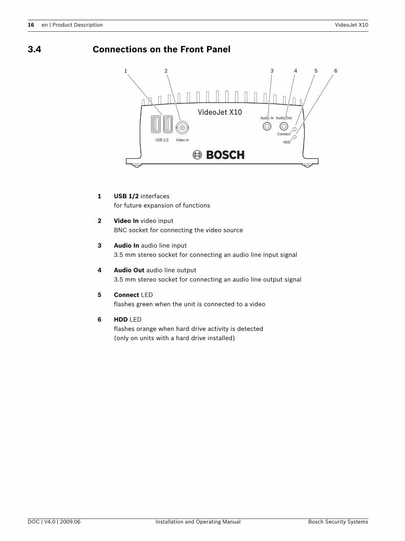
3.4 Connections on the Front Panel
1 USB 1/2 interfacesfor future expansion of functions
2 Video In video inputBNC socket for connecting the video source
3 Audio In audio line input3.5 mm stereo socket for connecting an audio line input signal
4 Audio Out audio line output3.5 mm stereo socket for connecting an audio line output signal
5 Connect LEDflashes green when the unit is connected to a video
6 HDD LEDflashes orange when hard drive activity is detected (only on units with a hard drive installed)
DOC | V4.0 | 2009.06 Installation and Operating Manual Bosch Security Systems

VideoJet X10 Product Description | en 17
3.5 Connections on the Rear Panel
7 ETH 1 RJ45 socketfor connecting to an Ethernet LAN (local network), 10/100 MBit Base-T
8 ETH 1 LEDlights up yellow when the unit is connected to the network via ETH 1
9 ETH 2 RJ45 socketfor a redundant connection to the network or to an iSCSI system
10 ETH 2 LEDlights up yellow when the unit is connected to the network via ETH 2
11 Terminal blockfor alarm inputs, relay outputs, serial interface and power supply
12 Power On LEDlights up green when ready for operation
13 Factory reset buttonto restore factory default settings
14 Compact Flash slotfor a CF card type I or type II
15 SFP LEDlights up yellow when the unit is connected via SFP
16 SFP slotfor mini-GBIC module
iNOTICE! For more information about the LEDs, see Section 8.4 LEDs, page 107.For terminal block assignment, see Section 8.8 Terminal Block, page 109.
Bosch Security Systems Installation and Operating Manual DOC | V4.0 | 2009.06

18 en | Product Description VideoJet X10
DOC | V4.0 | 2009.06 Installation and Operating Manual Bosch Security Systems

VideoJet X10 Installation | en 19
4 Installation
4.1 PreparationsThe VideoJet X10 features industrial standard equipment and is therefore suitable for both stationary installation and mobile installation in vehicles.
Please ensure the following installation conditions:– Do not install the unit close to heaters or other heat sources. Avoid locations exposed to
direct sunlight.– Allow sufficient space for running cables.– Ensure that the unit has adequate ventilation.– When making connections, use only the cables supplied or use appropriate cables
immune to electromagnetic interference. – Position and run all cables so that they are protected from damage, and provide
adequate cable strain relief where needed.– Avoid impacts, blows and severe vibrations that exceed the specification limits (see
Section 9 Specifications, page 113), as these can irreparably damage the unit.
4.2 MountingThe VideoJet X10 can be permanently mounted to walls, below ceilings or other load-bearing locations using the four drillings in the unit's base.
!
CAUTION! The unit is intended for use indoors or in housings.Select a suitable location for installation that guarantees to meet the environmental conditions. The ambient temperature must be between –30 and +60 °C (–22 and +140 °F). The relative humidity must not exceed 95%.The VideoJet X10 generates heat during operation, so you should ensure that there is adequate ventilation and enough clearance between the unit and heat-sensitive objects or equipment.
!
CAUTION! The front panel of the VideoJet X10 (video input) must not be pointing upwards, as internal heat dissipation is not guaranteed in this position. All other installation positions are permitted.Make sure that the mounting location (for example wall or ceiling) can reliably hold the unit. The load bearing capacity must be adequate for four times the weight of the unit.For mounting on metal, use screws with the following minimum specification: M4 × 8, 8.8, DIN ISO 4017.For mounting on concrete, use screws with the following minimum specification: M4 × 40 mm (1.57 in) and 6 mm (0.23 in) plastic dowels, for example fischer S4, type 50106.
Bosch Security Systems Installation and Operating Manual DOC | V4.0 | 2009.06

20 en | Installation VideoJet X10
4.3 ConnectionsCameraYou can connect a video source to the VideoJet X10. Any cameras and other video sources that produce a standard PAL or NTSC signal are suitable.1. Connect the camera or another video source to the BNC Video In socket using a video
cable (75 Ohm, BNC plug).2. If the video signal is not looped through, termination is performed by a software setting if
necessary (see Section 5.17 Advanced Mode: Video Input, page 45).
Audio ConnectionsThe VideoJet X10 has two audio ports for audio line signals.The audio signals are transmitted two-way and in sync with the video signals. As a result, you can connect a speaker or door intercom system at the destination point, for example. The following specifications should be complied with in all cases.
The stereo plugs must be connected as follows:
1. Connect an audio source with line level to the Audio In socket of the VideoJet X10 with a 3.5 mm stereo plug.
2. Connect a unit with line-in connection to the Audio Out socket of the VideoJet X10 with a 3.5 mm stereo plug.
NetworkYou can connect the VideoJet X10 to a 10/100 Base-T network using a standard UTP category 5 cable with RJ45 plugs. The second Ethernet interface can be used to create a redundant connection to the network.
1. Connect the VideoJet X10 to the network via the ETH 1 socket.2. Connect the VideoJet X10 to a redundant switch or hub on the same network via the
ETH 2 socket.
1 × Line In: Impedance 9 kOhm typ., 5.5 Vp-p max. input voltage
1 × Line Out: Impedance 10 kOhm typ., 3.0 Vp-p max. output voltage,
impedance 16 Ohm min., 1.7 Vp-p max. output voltage
Contact Line In function Line Out function
Tip Channel 1 Channel 1
Middle ring – –
Lower ring Ground Ground
iNOTICE! You cannot create a connection to a second network.
DOC | V4.0 | 2009.06 Installation and Operating Manual Bosch Security Systems
VideoJet X10 Installation | en 21
SFP SlotYou can establish an additional network connection by inserting a mini-GBIC module into the SFP slot for example via fiber optic cables (OF).
Direct iSCSI ConnectionYou can connect the VideoJet X10 directly to an iSCSI system via one of the network interfaces. For ETH 1 or ETH 2 connections, use a UTP category 5 network cable with RJ45 plugs.
CF SlotYou can insert a type I or II CompactFlash card into the Compact Flash slot to enable recordings to be saved locally. CF cards are the ideal solution for shorter storage times and temporary recordings, for example alarm recordings or local buffering in the event of network interruptions.
Playing back recordings is also possible using a different VideoJet X10, a VideoJet X20 or a VideoJet X40.
1. Carefully slide the CF card, top side down, into the slot as far as it will go.2. To remove the CF card, push the eject button to its right and then take out the card.
!CAUTION! Only laser class 1 transceivers are approved for use in the VideoJet X10.Use only approved modules.
iNOTICE! You can obtain a list of compatible iSCSI systems from your supplier or directly from Bosch Security Systems. This list is constantly being updated and extended.
iNOTICE! You can obtain a list of compatible CF cards from your supplier or directly from Bosch Security Systems. This list is constantly being updated and extended.
!CAUTION! If the card is formatted, all existing data is deleted from the card.You should therefore check whether the CF card contains any data that needs to be backed up before it is inserted.
Bosch Security Systems Installation and Operating Manual DOC | V4.0 | 2009.06
22 en | Installation VideoJet X10
Data InterfaceThe bidirectional data interface is used to control units connected to the VideoJet X10, such as a dome camera with a motorized lens. The connection supports the RS-232, RS-422 and RS-485 transmission standards.The VideoJet X10 offers the serial interface via the orange terminal block (see Section 8.8 Terminal Block, page 109).The range of controllable equipment is expanding constantly. The manufacturers of the relevant equipment provide specific information on installation and control.
Alarm InputsThe VideoJet X10 has four alarm inputs on the orange terminal block (see Section 8.8 Terminal Block, page 109). The alarm inputs are used to connect to external alarm devices such as door contacts or sensors. With the appropriate configuration, an alarm sensor can automatically connect the VideoJet X10 to a remote location, for example.A zero potential closing contact or switch can be used as the actuator.
Connect the lines to the appropriate terminals on the orange terminal block (IN1 to IN4) and check that the connection is secure.
!CAUTION! Please take note of the appropriate documentation when installing and operating the unit to be controlled.The documentation contains important safety instructions and information about permitted uses.
iNOTICE! A video connection is necessary to transmit transparent data.
iNOTICE! If possible, use a bounce-free contact system as the actuator.
DOC | V4.0 | 2009.06 Installation and Operating Manual Bosch Security Systems
VideoJet X10 Installation | en 23
Relay OutputsThe VideoJet X10 has four relay outputs for switching external units such as lamps or alarm sirens. You can operate these relay outputs manually while there is an active connection to the VideoJet X10. The outputs can also be configured to automatically activate sirens or other alarm units in response to an alarm signal. The relay outputs are also located on the orange terminal block (see Section 8.8 Terminal Block, page 109).
Connect the lines to the appropriate terminals on the orange terminal block (R1 to R4) and check that the connection is secure.
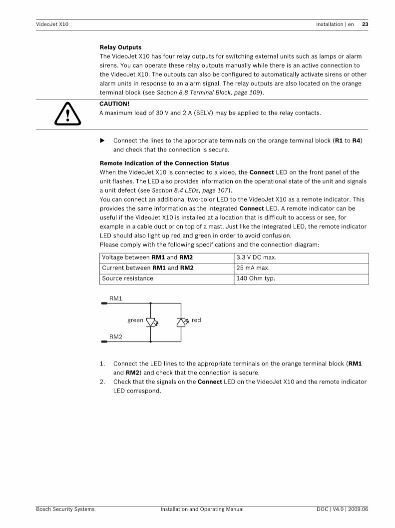
Remote Indication of the Connection StatusWhen the VideoJet X10 is connected to a video, the Connect LED on the front panel of the unit flashes. The LED also provides information on the operational state of the unit and signals a unit defect (see Section 8.4 LEDs, page 107).You can connect an additional two-color LED to the VideoJet X10 as a remote indicator. This provides the same information as the integrated Connect LED. A remote indicator can be useful if the VideoJet X10 is installed at a location that is difficult to access or see, for example in a cable duct or on top of a mast. Just like the integrated LED, the remote indicator LED should also light up red and green in order to avoid confusion.Please comply with the following specifications and the connection diagram:
1. Connect the LED lines to the appropriate terminals on the orange terminal block (RM1 and RM2) and check that the connection is secure.
2. Check that the signals on the Connect LED on the VideoJet X10 and the remote indicator LED correspond.
!CAUTION! A maximum load of 30 V and 2 A (SELV) may be applied to the relay contacts.
Voltage between RM1 and RM2 3.3 V DC max.
Current between RM1 and RM2 25 mA max.
Source resistance 140 Ohm typ.
Bosch Security Systems Installation and Operating Manual DOC | V4.0 | 2009.06

24 en | Installation VideoJet X10
Backup Power SupplyWhen used in mobile vehicles (for example public transport), the VideoJet X10 is usually switched on when the vehicle is started with the ignition key. If the ignition is switched off, the power supply to the unit is also stopped. To keep the internal clock running when the engine is off, you can connect the VideoJet X10 directly to the car battery via the BP and GND contacts. The correct time is crucial for evaluating local recordings.
1. Connect the + (plus) line on the car battery to the BP terminal on the orange terminal block.
2. Connect the – (minus) line on the car battery to the GND terminal on the orange terminal block.
3. Now check that the connections are secure.
!CAUTION! Connect only batteries with the following specification: 10 to 30 V DC, 50 Ah max., 12/24 V continuous flow.
iNOTICE! If you do not connect a battery to the unit, you should specify a time server to ensure correct system time.
DOC | V4.0 | 2009.06 Installation and Operating Manual Bosch Security Systems
VideoJet X10 Installation | en 25
4.4 Power On/Power OffPower SupplyThe VideoJet X10 does not have a power switch. Power is supplied via a separate unit. Connect the VideoJet X10 to the power supply unit and plug this into the mains. The unit is now ready for use. The VideoJet X10 does not come supplied with a power supply unit.
1. Plug the terminal block with the PSU cable connected to it into the orange socket on the VideoJet X10.
2. Connect the power supply unit to the mains. The VideoJet X10 is ready for use as soon as the Connect LED changes from a red light, indicating the start-up procedure, to a green light.
If the network connection has been set up correctly, the yellow ETH 1 or ETH 2 LED will also light up. A flashing ETH 1 or ETH 2 LED signals that data packages are being transmitted over the network.
4.5 Setup Using the Configuration ManagerThe Configuration Manager program can be found on the product CD contained in the scope of delivery. This program allows you to implement and set up new video servers in the network quickly and conveniently.
Installing the Program1. Insert the CD into the computer's CD-ROM drive. 2. If the CD does not start automatically, open the Configuration Manager directory using
Windows Explorer and double-click Setup.exe.3. Follow the on-screen instructions.
!
CAUTION! Use only power supply units with UL approval and a power output according to LPS or NEC Class 2.Where necessary, use suitable equipment to ensure that the power supply is free from interference such as voltage surges, spikes or voltage drops.Do not connect the VideoJet X10 to the power supply until all other connections have been made.
iNOTICE! Using the Configuration Manager to set all parameters in the VideoJet X10 is an alternative to configuration by means of a Web browser, as described in chapter 5 of this manual.
Bosch Security Systems Installation and Operating Manual DOC | V4.0 | 2009.06

26 en | Installation VideoJet X10
Configuring the VideoJet X10You can start the Configuration Manager immediately after installation.1. Double-click the icon on the desktop or start the program via the Start menu. After the
program has started, the network is immediately searched for compatible video servers.
2. You can start the configuration if a VideoJet X10 is shown in the list in the left section of the window. To do this, right-click the entry for the unit.
3. Click Unit network settings... in the popup menu.4. In the Unit IP address field, enter a valid IP address to operate on your network (for
example 192.168.0.10) and click OK. The unit reboots and the IP address is valid.5. If required, enter an appropriate subnet mask for the IP address, and additional network
data.
RebootYou can trigger the reboot directly with the assistance of the Configuration Manager.
Right-click the entry for the unit in the list in the left section of the window and select the Reset command from the context menu.
Additional ParametersYou can check and set additional parameters with the assistance of the Configuration Manager. You can find detailed information on this in the documentation for this program.
iNOTICE! You must reboot to activate the new IP address, a new subnet mask or a gateway IP address.
DOC | V4.0 | 2009.06 Installation and Operating Manual Bosch Security Systems

VideoJet X10 Configuration Using a Web Browser | en 27
5 Configuration Using a Web Browser
5.1 ConnectingThe integrated HTTP server in the VideoJet X10 provides you with the option to configure the unit over the network with a Web browser. This option is an alternative to configuration using the Configuration Manager program and is considerably richer in function and more convenient than configuration using the terminal program.
System Requirements– Computer with Windows XP or Windows Vista operating system– Network access (Intranet or Internet)– Microsoft Internet Explorer (version 6.0 or higher)– Screen resolution 1,024 × 768 pixels– 16- or 32-bit color depth– Installed Sun JVM
Installing MPEG ActiveXSuitable MPEG ActiveX software must be installed on the computer to allow the live video images to be played back. If necessary, you can install the program from the product CD supplied.1. Insert the product CD into the computer's CD-ROM drive. If the CD does not start
automatically, open the root directory of the CD in Windows Explorer and double-click MPEGAx.exe.
2. Follow the on-screen instructions.
i
NOTICE! Also note the information in the System Requirements document on the product CD supplied. If necessary, you can install the required programs and controls from the product CD supplied (see Section 3.1 Scope of Delivery, page 11).The Web browser must be configured to enable Cookies to be set from the IP address of the unit.In Windows Vista, deactivate protected mode on the Security tab under Internet Options.You can find notes on using Microsoft Internet Explorer in the online Help in Internet Explorer.
Bosch Security Systems Installation and Operating Manual DOC | V4.0 | 2009.06

28 en | Configuration Using a Web Browser VideoJet X10
Establishing the ConnectionBefore you can operate the VideoJet X10 within your network, it must have a valid IP address for your network and a compatible subnet mask.The following default address is preset at the factory: 192.168.0.11. Start the Web browser.2. Enter the IP address of the VideoJet X10 as the URL. The connection is established and
after a short time you will see the LIVEPAGE with the video image.
Maximum Number of ConnectionsIf you do not connect, the unit may have reached its maximum number of connections. Depending on the unit and network configuration, each VideoJet X10 can have up to 25 Web browser connections or up to 50 connections via VIDOS or Bosch Video Management System.
DOC | V4.0 | 2009.06 Installation and Operating Manual Bosch Security Systems
VideoJet X10 Configuration Using a Web Browser | en 29
Protected VideoJet X10If the VideoJet X10 is password protected against unauthorized access, the Web browser displays a corresponding message and prompts you to enter the password when you attempt to access protected areas.
1. Enter the user name and associated password in the corresponding text fields.2. Click OK. If the password is entered correctly, the Web browser displays the page that
was called up.
Protected NetworkIf a RADIUS server is employed in the network for managing access rights (802.1x authentication), the VideoJet X10 must be configured accordingly, otherwise no communication is possible.To configure the unit, you must connect the VideoJet X10 directly to a computer using a network cable. This is because communication via the network is not enabled until the Identity and Password parameters have been set and successfully authenticated (see Section Authentication, page 81).
5.2 Configuration MenuThe SETTINGS page provides access to the configuration menu, which contains all the unit's parameters arranged in groups. You can view the current settings by opening one of the configuration screens. You can change the settings by entering new values or by selecting a predefined value from a list field.There are two options for configuring the unit or checking the current settings:– Basic mode– Advanced modeIn Basic Mode the most important parameters are arranged in seven groups. This allows you to change the basic settings with just a few entries and then put the device into operation.Advanced Mode is recommended for expert users or system support personnel. You can access all unit parameters in this mode. Settings that affect the fundamental functionality of the unit (such as firmware updates) can only be altered in the advanced mode.All parameter groups are described in this chapter in the order in which they are listed in the configuration menu, from the top of the screen to the bottom.
All settings are backed up in the VideoJet X10 memory so they are not lost even if the power fails.
iNOTICE! The VideoJet X10 offers the option to limit the extent of access using various authorization levels (see Section 5.11 Advanced Mode: Password, page 38).
!CAUTION! The settings in the advanced mode should only be processed or modified by expert users or system support personnel.
Bosch Security Systems Installation and Operating Manual DOC | V4.0 | 2009.06

30 en | Configuration Using a Web Browser VideoJet X10
Starting ConfigurationClick the SETTINGS link in the upper section of the window. The Web browser opens a new page with the configuration menu.
Navigation1. Click one of the menu items in the left window margin. The corresponding submenu is
displayed.2. Click one of the entries in the submenu. The Web browser opens the corresponding
page.
Making ChangesEach configuration screen shows the current settings. You can change the settings by entering new values or by selecting a predefined value from a list field.
After each change, click Set to save the change.
!CAUTION! Save each change with the associated Set button.Clicking the Set button saves the settings only in the current field. Changes in any other fields are ignored.
DOC | V4.0 | 2009.06 Installation and Operating Manual Bosch Security Systems

VideoJet X10 Configuration Using a Web Browser | en 31
5.3 Basic Mode: Unit Access
Device nameYou can give the VideoJet X10 a name to make it easier to identify. The name makes the task of administering multiple units in larger video monitoring systems easier, for example using the VIDOS or Bosch Video Management System programs.The device name is used for the remote identification of a unit, in the event of an alarm for example. For this reason, enter a name that makes it as easy as possible to quickly identify the location.
Camera 1The camera name makes it easier to identify the remote camera location, in the event of an alarm for example. It will be displayed in the video screen if configured to do so (see Section Camera name stamping, page 40). The camera name makes the task of administering cameras in larger video monitoring systems easier, for example using the VIDOS or Bosch Video Management System programs.Enter a unique, unambiguous name for the camera in this field.
PasswordA VideoJet X10 is generally protected by a password to prevent unauthorized access to the unit. You can use different authorization levels to limit access.The VideoJet X10 operates with three authorization levels: service, user and live.
!CAUTION! Do not use any special characters, for example &, in the name.Special characters are not supported by the system's internal recording management and may therefore result in the Player or Archive Player being unable to play back the recording.
!CAUTION! Do not use any special characters, for example &, in the name.Special characters are not supported by the system's internal recording management and may therefore result in the Player or Archive Player being unable to play back the recording.
Bosch Security Systems Installation and Operating Manual DOC | V4.0 | 2009.06

32 en | Configuration Using a Web Browser VideoJet X10
The highest authorization level is service. After entering the correct password, you can access all the functions of the VideoJet X10 and change all configuration settings.With the user authorization level, you can operate the unit and also control cameras, for example, but you cannot change the configuration.The lowest authorization level is live. It can only be used to view the live video image and switch between the different live image displays.You can define and change a password for each authorization level if you are logged in as service or if the unit is not password protected.Enter the password for the appropriate authorization level here.
Confirm passwordIn each case, enter the new password a second time to eliminate typing mistakes.
5.4 Basic Mode: Date/Time
Unit date/Unit time/Unit time zoneIf there are multiple devices operating in your system or network, it is important to synchronize their internal clocks. For example, it is only possible to identify and correctly evaluate simultaneous recordings when all units are operating on the same time. If necessary, you can synchronize the unit with your computer's system settings.
Click the Sync to PC button to copy your computer's system time to the VideoJet X10.
Time server IP addressThe VideoJet X10 can receive the time signal from a time server using various time server protocols, and then use it to set the internal clock. The unit polls the time signal automatically once every minute.
Enter the IP address of a time server here.
iNOTICE! Proper password protection is only guaranteed when all higher authorization levels are also protected with a password. If a live password is assigned, for example, a service and a user password must also be set. When assigning passwords, you should therefore always start from the highest authorization level, service, and use different passwords.
iNOTICE! A new password is only saved when you click the Set button. You should therefore click the Set button immediately after entering and confirming a password.
DOC | V4.0 | 2009.06 Installation and Operating Manual Bosch Security Systems

VideoJet X10 Configuration Using a Web Browser | en 33
Time server typeSelect the protocol that is supported by the selected time server. Preferably, you should select the SNTP server as the protocol. This supports a high level of accuracy and is required for special applications and subsequent function extensions.Select Time server for a time server that works with the protocol RFC 868.
5.5 Basic Mode: Network
The settings on this page are used to integrate the VideoJet X10 into an existing network.Some changes only take effect after the unit is rebooted. In this case, the Set button changes to Set and Reboot.1. Make the desired changes.2. Click the Set and Reboot button. The VideoJet X10 is rebooted and the changed settings
are activated.
DHCPIf a DHCP server is employed in the network for the dynamic assignment of IP addresses, you can activate acceptance of IP addresses automatically assigned to the VideoJet X10.Certain applications (VIDOS, Bosch Video Management System, Archive Player, Configuration Manager) use the IP address for the unique assignment of the unit. If you use these applications, the DHCP server must support the fixed assignment between IP address and MAC address, and must be appropriately set up so that, once an IP address is assigned, it is retained each time the system is rebooted.
IP addressEnter the desired IP address for the VideoJet X10 in this field. The IP address must be valid for the network.
Subnet maskEnter the appropriate subnet mask for the selected IP address here.
Gateway addressIf you want the unit to establish a connection to a remote location in a different subnet, enter the IP address of the gateway here. Otherwise leave the box blank (0.0.0.0).
!CAUTION! If you change the IP address, subnet mask or gateway address, the VideoJet X10 is only available under the new addresses after the reboot.
Bosch Security Systems Installation and Operating Manual DOC | V4.0 | 2009.06
34 en | Configuration Using a Web Browser VideoJet X10
5.6 Basic Mode: Encoder Profile
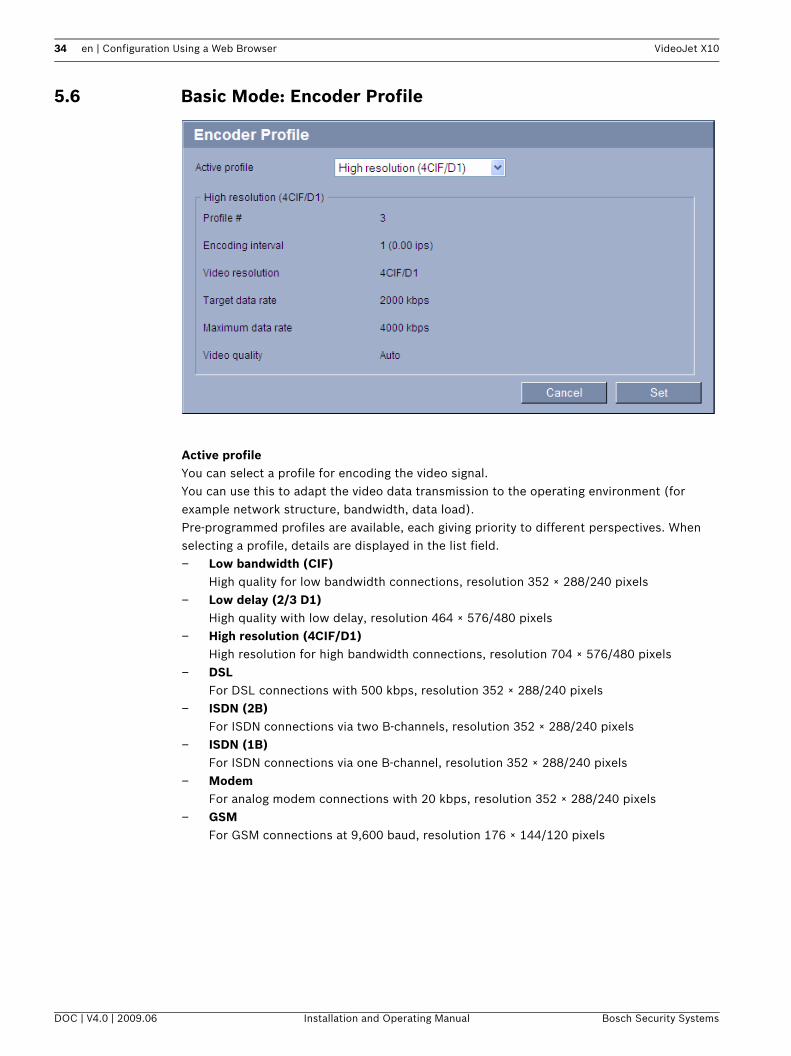
Active profileYou can select a profile for encoding the video signal.You can use this to adapt the video data transmission to the operating environment (for example network structure, bandwidth, data load).Pre-programmed profiles are available, each giving priority to different perspectives. When selecting a profile, details are displayed in the list field.– Low bandwidth (CIF)
High quality for low bandwidth connections, resolution 352 × 288/240 pixels– Low delay (2/3 D1)
High quality with low delay, resolution 464 × 576/480 pixels– High resolution (4CIF/D1)
High resolution for high bandwidth connections, resolution 704 × 576/480 pixels– DSL
For DSL connections with 500 kbps, resolution 352 × 288/240 pixels– ISDN (2B)
For ISDN connections via two B-channels, resolution 352 × 288/240 pixels– ISDN (1B)
For ISDN connections via one B-channel, resolution 352 × 288/240 pixels– Modem
For analog modem connections with 20 kbps, resolution 352 × 288/240 pixels– GSM
For GSM connections at 9,600 baud, resolution 176 × 144/120 pixels
DOC | V4.0 | 2009.06 Installation and Operating Manual Bosch Security Systems

VideoJet X10 Configuration Using a Web Browser | en 35
5.7 Basic Mode: Audio
You can set the gain of the audio signals to suit your specific requirements. The current video image is shown in the small window next to the slide controls to help you check the audio source and improve assignments. Your changes are effective immediately.If you connect via Web browser, you must activate the audio transmission on the LIVEPAGE Functions page (see Section 5.15 Advanced Mode: LIVEPAGE Functions, page 43). For other connections, the transmission depends on the audio settings of the respective system.
AudioThe audio signals are sent in a separate data stream parallel to the video data, and so increase the network load. The audio data are encoded according to G.711 and require an additional bandwidth of approx. 80 kbps for each connection. If you do not want any audio data to be transmitted, select Off.
Line In 1You can set the line input gain. Make sure that the display does not go beyond the green zone during modulation.
Line OutYou can set the line output gain. Make sure that the display does not go beyond the green zone during modulation.
Bosch Security Systems Installation and Operating Manual DOC | V4.0 | 2009.06

36 en | Configuration Using a Web Browser VideoJet X10
5.8 Basic Mode: Recording
You can record the images from the camera connected to the VideoJet X10 on various local storage media or on an appropriately configured iSCSI system.CF cards (see Section CF Slot, page 21) are the ideal solution for shorter storage times.If the VideoJet X10 has a hard drive, this is suitable for longer, local recordings in mobile use.For long-term, authoritative images in stationary operation, it is essential that you use an appropriately sized iSCSI system.Here you can select a storage medium and immediately start or stop the recording.
Storage medium1. Select the required storage medium from the list.2. Click the Start button to start the recording immediately.
5.9 Basic Mode: System Overview
The data on this page are for information purposes only and cannot be changed. Keep a record of this information in case technical assistance is required.
iNOTICE! You can select all required text on this page with the mouse and copy it to the clipboard with the [Ctrl]+[C] key combination, for example if you want to send it via e-mail.
DOC | V4.0 | 2009.06 Installation and Operating Manual Bosch Security Systems
VideoJet X10 Configuration Using a Web Browser | en 37
5.10 Advanced Mode: Identification
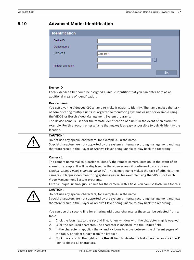
Device IDEach VideoJet X10 should be assigned a unique identifier that you can enter here as an additional means of identification.
Device nameYou can give the VideoJet X10 a name to make it easier to identify. The name makes the task of administering multiple units in larger video monitoring systems easier, for example using the VIDOS or Bosch Video Management System programs.The device name is used for the remote identification of a unit, in the event of an alarm for example. For this reason, enter a name that makes it as easy as possible to quickly identify the location.
Camera 1The camera name makes it easier to identify the remote camera location, in the event of an alarm for example. It will be displayed in the video screen if configured to do so (see Section Camera name stamping, page 40). The camera name makes the task of administering cameras in larger video monitoring systems easier, for example using the VIDOS or Bosch Video Management System programs.Enter a unique, unambiguous name for the camera in this field. You can use both lines for this.
You can use the second line for entering additional characters; these can be selected from a table.1. Click the icon next to the second line. A new window with the character map is opened.2. Click the required character. The character is inserted into the Result field.3. In the character map, click the << and >> icons to move between the different pages of
the table, or select a page from the list field.4. Click the < icon to the right of the Result field to delete the last character, or click the X
icon to delete all characters.
!CAUTION! Do not use any special characters, for example &, in the name.Special characters are not supported by the system's internal recording management and may therefore result in the Player or Archive Player being unable to play back the recording.
!CAUTION! Do not use any special characters, for example &, in the name.Special characters are not supported by the system's internal recording management and may therefore result in the Player or Archive Player being unable to play back the recording.
Bosch Security Systems Installation and Operating Manual DOC | V4.0 | 2009.06
38 en | Configuration Using a Web Browser VideoJet X10
5. Now click the OK button to apply the selected characters to the second line of the Camera 1 parameters. The window will close.
Initiator extensionYou can attach your own text to the initiator name of the VideoJet X10 to make the unit easier to identify in large iSCSI systems. This text is added to the initiator name, separated from it by a full stop. You can see the initiator name in the system overview (see Section 5.9 Basic Mode: System Overview, page 36).
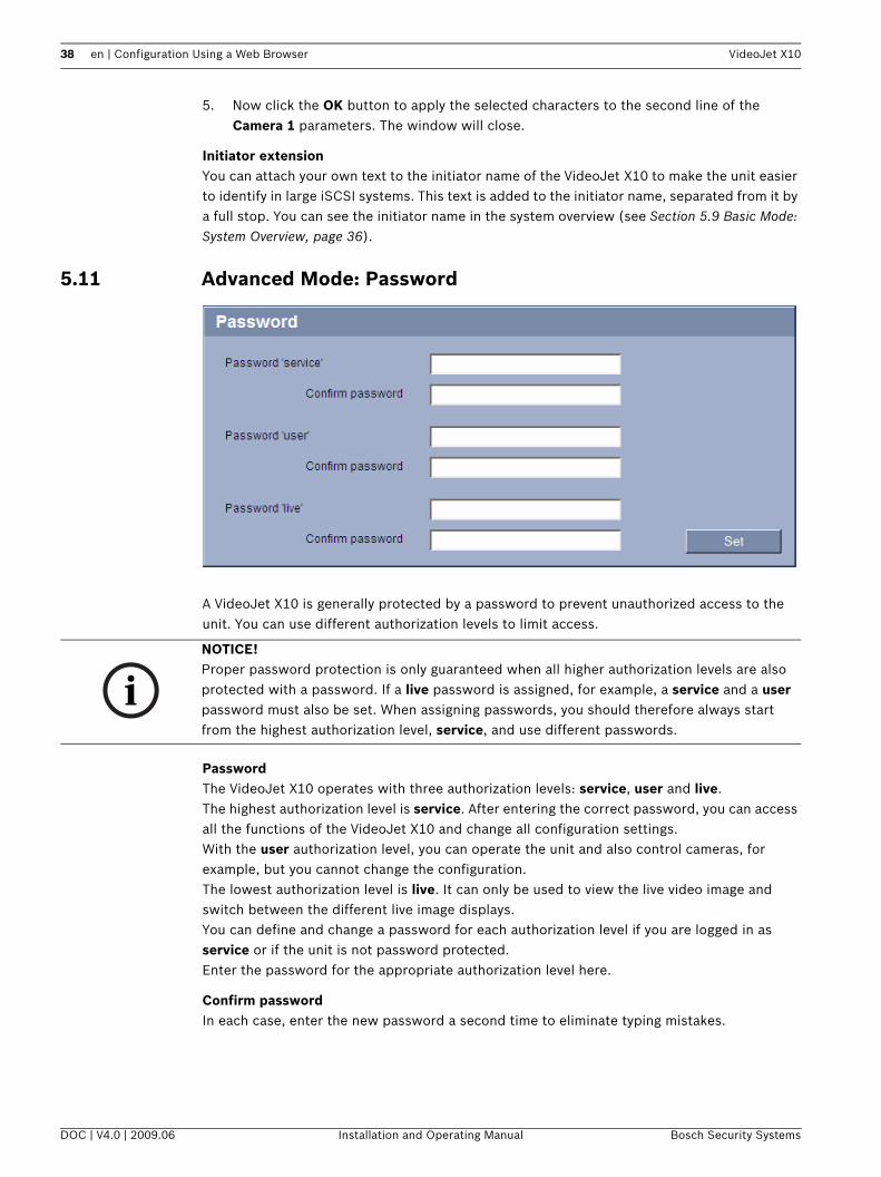
5.11 Advanced Mode: Password
A VideoJet X10 is generally protected by a password to prevent unauthorized access to the unit. You can use different authorization levels to limit access.
PasswordThe VideoJet X10 operates with three authorization levels: service, user and live.The highest authorization level is service. After entering the correct password, you can access all the functions of the VideoJet X10 and change all configuration settings.With the user authorization level, you can operate the unit and also control cameras, for example, but you cannot change the configuration.The lowest authorization level is live. It can only be used to view the live video image and switch between the different live image displays.You can define and change a password for each authorization level if you are logged in as service or if the unit is not password protected.Enter the password for the appropriate authorization level here.
Confirm passwordIn each case, enter the new password a second time to eliminate typing mistakes.
iNOTICE! Proper password protection is only guaranteed when all higher authorization levels are also protected with a password. If a live password is assigned, for example, a service and a user password must also be set. When assigning passwords, you should therefore always start from the highest authorization level, service, and use different passwords.
DOC | V4.0 | 2009.06 Installation and Operating Manual Bosch Security Systems

VideoJet X10 Configuration Using a Web Browser | en 39
5.12 Advanced Mode: Date/Time
Date formatSelect your required date format.
Unit date/Unit timeIf there are multiple devices operating in your system or network, it is important to synchronize their internal clocks. For example, it is only possible to identify and correctly evaluate simultaneous recordings when all units are operating on the same time.1. Enter the current date. Since the unit time is controlled by the internal clock, there is no
need to enter the day of the week – it is added automatically.2. Enter the current time or click the Sync to PC button to copy your computer's system
time to the VideoJet X10.
Unit time zoneSelect the time zone in which your system is located.
Daylight saving timeThe internal clock can switch automatically between normal and daylight saving time (DST). The unit already contains the data for DST switch-overs up to the year 2018. You can use these data or create alternative time saving data if required.
1. First check whether the correct time zone is selected. If it is not correct, select the appropriate time zone for the system, and click the Set button.
2. Click the Details button. A new window will open and you will see the empty table.3. Select the region or the city that is closest to the system's location from the list field
below the table.4. Click the Generate button to generate data and enter it into the table.
iNOTICE! A new password is only saved when you click the Set button. You should therefore click the Set button immediately after entering and confirming a password.
iNOTICE! If you do not create a table, there will be no automatic switching. When changing and clearing individual entries, remember that two entries are usually related to each other and dependent on one another (switching to summer time and back to normal time).
Bosch Security Systems Installation and Operating Manual DOC | V4.0 | 2009.06

40 en | Configuration Using a Web Browser VideoJet X10
5. Make changes by clicking an entry in the table. The entry is selected.6. Clicking the Delete button will remove the entry from the table.7. Select other values from the list fields below the table to change the entry. Changes are
made immediately.8. If there are empty lines at the bottom of the table, for example after deletions, you can
add new data by marking the row and selecting required values from the list fields.9. Now click the OK button to save and activate the table.
Time server IP addressThe VideoJet X10 can receive the time signal from a time server using various time server protocols, and then use it to set the internal clock. The unit polls the time signal automatically once every minute.Enter the IP address of a time server here.
Time server typeSelect the protocol that is supported by the selected time server. Preferably, you should select the SNTP server as the protocol. This supports a high level of accuracy and is required for special applications and subsequent function extensions.Select Time server for a time server that works with the protocol RFC 868.
5.13 Advanced Mode: Display Stamping
Various overlays or "stamps" in the video image provide important supplementary information. These overlays can be enabled individually and are arranged on the image in a clear manner.
Camera name stampingThis field sets the position of the camera name overlay. It can be displayed at the Top, at the Bottom or at a position of your choice that you can then specify using the Custom option. Or it can be set to Off for no overlay information.1. Select the desired option from the list.2. If you select the Custom option, additional fields are displayed where you can specify the
exact position (Position (XY)).3. In the Position (XY) fields, enter the values for the desired position.
Time stampingThis field sets the position of the time overlay. It can be displayed at the Top, at the Bottom or at a position of your choice that you can then specify using the Custom option. Or it can be set to Off for no overlay information.1. Select the desired option from the list.
DOC | V4.0 | 2009.06 Installation and Operating Manual Bosch Security Systems

VideoJet X10 Configuration Using a Web Browser | en 41
2. If you select the Custom option, additional fields are displayed where you can specify the exact position (Position (XY)).
3. In the Position (XY) fields, enter the values for the desired position.
Display millisecondsIf necessary, you can also display milliseconds. This information can be useful for recorded video images; however, it does increase the processor's computing time. Select Off if you do not need to display milliseconds.
Alarm mode stampingSelect On to display a text message overlay in the event of an alarm. It can be displayed at a position of your choice that you can then specify using the Custom option. Or it can be set to Off for no overlay information.1. Select the desired option from the list.2. If you select the Custom option, additional fields are displayed where you can specify the
exact position (Position (XY)).3. In the Position (XY) fields, enter the values for the desired position.
Alarm messageEnter the message to be displayed in the event of an alarm. The maximum text length is 31 characters.
Video watermarkingChoose On if you wish the transmitted video images to be "watermarked". After activation, all images are marked with a green W. A red W indicates that the sequence (live or saved) has been manipulated.
5.14 Advanced Mode: Appearance
On this page you can adapt the appearance of the web interface and change the website language to meet your requirements. If necessary, you can replace the manufacturer's logo (top right) and the product name (top left) in the top part of the window with individual graphics.
iNOTICE! You can use either GIF or JPEG images. The file paths must correspond to the access mode (for example C:\Images\Logo.gif for access to local files, or http://www.mycompany.com/images/logo.gif for access via the Internet/Intranet). When accessing via the Internet/Intranet, ensure that a connection is always available to display the image. The image file is not stored in the VideoJet X10.
Bosch Security Systems Installation and Operating Manual DOC | V4.0 | 2009.06

42 en | Configuration Using a Web Browser VideoJet X10
Website languageSelect the language for the user interface here.
Company logoEnter the path to a suitable graphic if you want to replace the manufacturer's logo. The image file can be stored on a local computer, in the local network or at an Internet address.
Device logoEnter the path to a suitable graphic if you want to replace the product name. The image file can be stored on a local computer, in the local network or at an Internet address.
JPEG sizeYou can choose between two given image sizes to display the M-JPEG image on the LIVEPAGE.
JPEG intervalYou can specify the interval at which the individual images should be generated for the M-JPEG image on the LIVEPAGE.
JPEG qualityYou can specify the image quality for displaying M-JPEG on the LIVEPAGE.
iNOTICE! There are always two languages to choose from: English and another language. If the language you require is not available for selection, you can download the current firmware with another language combination from the website www.boschsecurity.com.
iNOTICE! If you want to use the original graphics again, simply delete the entries in the Company logo and Device logo fields.
DOC | V4.0 | 2009.06 Installation and Operating Manual Bosch Security Systems

VideoJet X10 Configuration Using a Web Browser | en 43
5.15 Advanced Mode: LIVEPAGE Functions
On this page you can adapt the LIVEPAGE functions to your requirements. You can choose from a variety of different options for displaying information and controls.
1. Check the box for the items that are to be made available on the LIVEPAGE. The selected items are indicated by a check mark.
2. Check whether the required functions are available on the LIVEPAGE.
Transmit audioThe audio signals are sent in a separate data stream parallel to the video data, and so increase the network load. The audio data are encoded according to G.711 and require an additional bandwidth of approx. 80 kbps for each connection.
Bilinx controlNext to the field for view control at the top left of the LIVEPAGE, an additional field is displayed for the special Bosch Security Systems Bilinx control.
Lease time (s)The lease time in seconds determines the time beyond which a different user is authorized to control the camera after no further control signals are received from the current user. After this time interval, the camera is automatically enabled.
Show alarm inputsAlarm inputs are shown next to the video image as icons, along with their assigned names. If an alarm is active, the corresponding icon changes color.
Show relay outputsRelay outputs are shown next to the video image as icons, along with their assigned names. If the relay is switched, the icon changes color.
Bosch Security Systems Installation and Operating Manual DOC | V4.0 | 2009.06

44 en | Configuration Using a Web Browser VideoJet X10
Show VCA trajectoriesThe trajectories (motion lines of objects) from the video content analysis are displayed in the live video image if a corresponding analysis type is activated (see Section 5.31 Advanced Mode: VCA Event Triggered, page 69).
Show VCA metadataWhen the analysis function is activated, the additional information from the video content analysis (VCA) will be displayed in the live video image (see Section 5.31 Advanced Mode: VCA Event Triggered, page 69). With the MOTION+ analysis type, for example, the sensor fields in which motion is recorded will be marked with rectangles.
Show event logThe event messages are displayed along with the date and time in a field next to the video image.
Show system logThe system messages are displayed along with the date and time in a field next to the video image and provide information about establishing and ending connections, for example.
Allow snapshotsHere you can specify whether the icon for saving individual images should be displayed below the live image. Individual images can only be saved if this icon is visible.
Allow local recordingHere you can specify whether the icon for saving video sequences on the local memory should be displayed below the live image. Video sequences can only be saved if this icon is visible.
Path for JPEG and MPEG files1. Enter the path for the storage location of individual images and video sequences that you
can save from the LIVEPAGE.2. If necessary, click Browse to find a suitable directory.
5.16 Advanced Mode: Logging
Save event logCheck this option to save event messages in a text file on your local computer.You can then view, edit and print this file with any text editor or the standard Office software.
File for event log1. Enter the path for saving the event log here.2. If necessary, click Browse to find a suitable directory.
Save system logCheck this option to save system messages in a text file on your local computer.
DOC | V4.0 | 2009.06 Installation and Operating Manual Bosch Security Systems
VideoJet X10 Configuration Using a Web Browser | en 45
You can then view, edit and print this file with any text editor or the standard Office software.
File for system log1. Enter the path for saving the system log here.2. If necessary, click Browse to find a suitable directory.
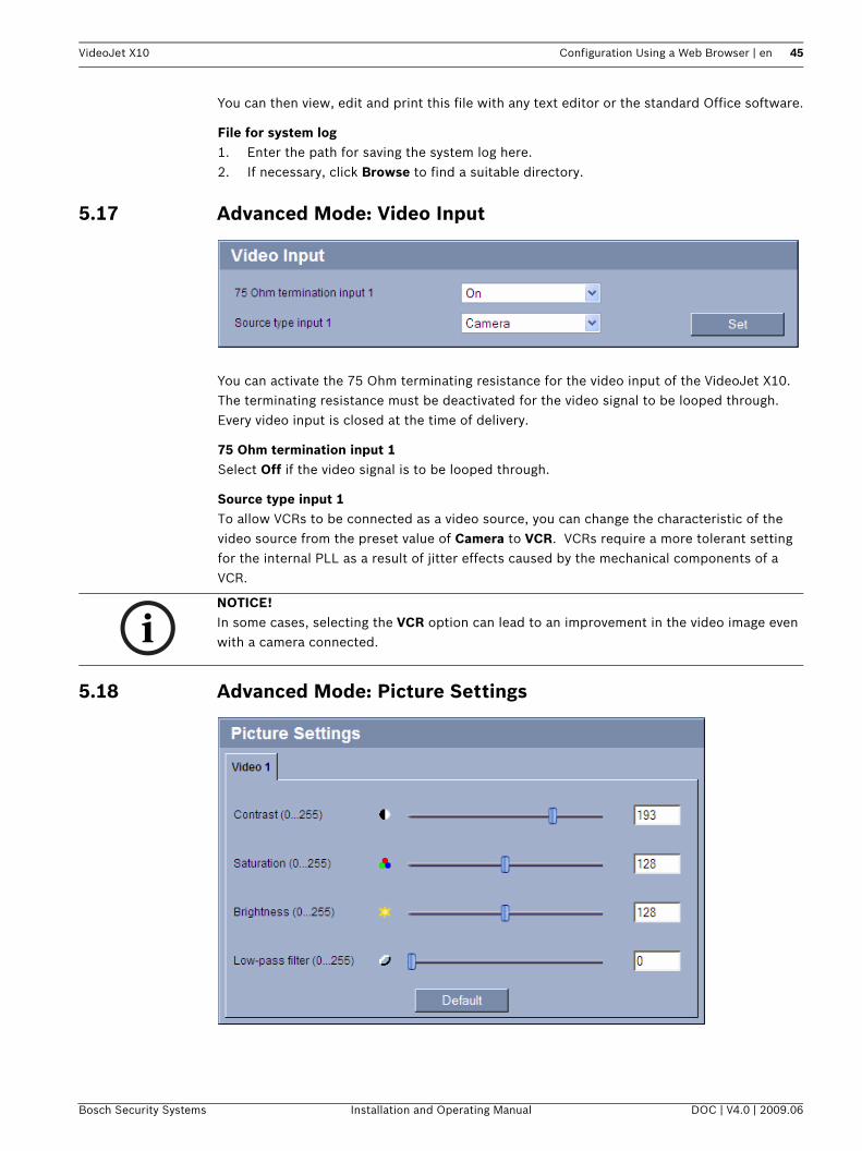
5.17 Advanced Mode: Video Input
You can activate the 75 Ohm terminating resistance for the video input of the VideoJet X10. The terminating resistance must be deactivated for the video signal to be looped through. Every video input is closed at the time of delivery.
75 Ohm termination input 1Select Off if the video signal is to be looped through.
Source type input 1To allow VCRs to be connected as a video source, you can change the characteristic of the video source from the preset value of Camera to VCR. VCRs require a more tolerant setting for the internal PLL as a result of jitter effects caused by the mechanical components of a VCR.
5.18 Advanced Mode: Picture Settings
iNOTICE! In some cases, selecting the VCR option can lead to an improvement in the video image even with a camera connected.
Bosch Security Systems Installation and Operating Manual DOC | V4.0 | 2009.06

46 en | Configuration Using a Web Browser VideoJet X10
You can set the video image of the camera to suit your requirements. The current video image is displayed in the small window next to the slide controls as confirmation. Your changes are effective immediately.1. Move the slide control to the required position.2. Click Default to reset all settings to their default value.
Contrast (0...255)You can use this function to adapt the contrast of the video image to your working environment.
Saturation (0...255)You can use this function to adjust the color saturation so as to make the reproduction of colors on your monitor as realistic as possible.
Brightness (0...255)You can use this function to adapt the brightness of the video image to your working environment.
Low-pass filter (0...255)You can use this function to filter very fine noise from the image. This reduces and optimizes the bandwidth necessary for image transmission over the network. The image resolution may be impaired.The higher the value set with the slide control, the flatter the image signal. Check your setting in the image window next to the slide controls.Also observe the processor load indicator that appears at the top of the window near the manufacturer's logo (see Section 8.6 Network Connection, page 108).
DOC | V4.0 | 2009.06 Installation and Operating Manual Bosch Security Systems

VideoJet X10 Configuration Using a Web Browser | en 47
5.19 Advanced Mode: Encoder Profile
For the video signal encoding, you can select a code algorithm for each and two profiles, and you can change the presets for the profiles.You can adapt the video data transmission to the operating environment (for example network structure, bandwidth, data load). To this end, the VideoJet X10 simultaneously generates two data streams (Dual Streaming), which compression settings you can select individually, for example one setting for transmissions to the Internet and one for LAN connections.Pre-programmed profiles are available, each giving priority to different perspectives.– Low bandwidth (CIF)
High quality for low bandwidth connections, resolution 352 × 288/240 pixels– Low delay (2/3 D1)
High quality with low delay, resolution 464 × 576/480 pixels
Bosch Security Systems Installation and Operating Manual DOC | V4.0 | 2009.06

48 en | Configuration Using a Web Browser VideoJet X10
– High resolution (4CIF/D1)High resolution for high bandwidth connections, resolution 704 × 576/480 pixels
– DSLFor DSL connections with 500 kbps, resolution 352 × 288/240 pixels
– ISDN (2B)For ISDN connections via two B-channels, resolution 352 × 288/240 pixels
– ISDN (1B)For ISDN connections via one B-channel, resolution 352 × 288/240 pixels
– ModemFor analog modem connections with 20 kbps, resolution 352 × 288/240 pixels
– GSMFor GSM connections at 9,600 baud, resolution 176 × 144/120 pixels
You can choose between the code algorithms MPEG-4 SH++ and H.264 for each data stream. H.264 requires a lower bandwidth at the same video quality but it does not offer 4CIF resolution. 4CIF resolution is only possible with MPEG-4 SH++.1. Select the required profile for every data stream.2. Select the required code algorithm for every data stream.
You can change individual parameter values of a profile and you can also change the name. You can switch between profiles by clicking the appropriate tabs.
Preview forSelect which video data stream should be displayed in the previews. You can deactivate the display of the video images if the performance of the computer is affected too strongly by the decoding of the data streams.1. Check the box for the required data stream.2. Click the i icon above the relevant preview to display further information about the data
stream.
Profile nameYou can enter a new name for the profile here. The name is then displayed in the list of available profiles in the Active profile field.
!
CAUTION! The profiles are rather complex. They include a large number of parameters that interact with one another, so it is generally best to use the default profiles.Change the profiles only once you are fully familiar with all the configuration options.In the default setting, Stream 2 is transmitted for alarm connections and automatic connections. Bear this fact in mind when assigning the profile.
iNOTICE! All parameters combine to make up a profile and are dependent on one another. If you enter a setting that is outside the permitted range for a particular parameter, the nearest permitted value will be substituted when the settings are saved.
DOC | V4.0 | 2009.06 Installation and Operating Manual Bosch Security Systems

VideoJet X10 Configuration Using a Web Browser | en 49
Target data rateYou can limit the data rate for the VideoJet X10 to optimize utilization of the bandwidth in your network. The target data rate should be set according to the desired picture quality for typical scenes with no excessive motion.For complex images or frequent changes of image content due to frequent movements, this limit can be temporarily exceeded up to the value you enter in the Maximum data rate field.
Encoding intervalThe figure selected here determines the interval at which images are encoded and transmitted. For example, entering 4 means that only every fourth image is encoded, the following three are skipped - this can be particularly advantageous with low bandwidths. The image rate in ips (images per second) is displayed next to the text field.
Video resolutionHere you can select the desired resolution for the video image. The following resolutions are available:– QCIF
176 × 144/120 pixels– CIF
352 × 288/240 pixels– 1/2 D1
352 × 576/480 pixels– 2CIF
704 × 288/240 pixels– 4CIF/D1
704 × 576/480 pixels– 2/3 D1
464 × 576/480 pixels
DefaultClick Default to return the profile to the factory default values.
DetailsClicking the Details >> button displays further details on image quality and data transmission. These settings require extensive knowledge of the MPEG standard and video data compression. Incorrect settings can render the video images unusable.
Maximum data rateThis maximum data rate is not exceeded under any circumstances. Depending on the video quality settings for the I- and P-frames, this fact can result in individual images being skipped.The value entered here must be at least 10% higher than the value entered in the Target data rate field. If the value entered here is too low, it will automatically be adjusted.
Bosch Security Systems Installation and Operating Manual DOC | V4.0 | 2009.06

50 en | Configuration Using a Web Browser VideoJet X10
I-frame distanceThis parameter allows you to set the intervals in which the I-frames will be coded. 0 means auto mode, whereby the video server inserts I-frames as necessary. An entry of 1 indicates that I-frames are continuously generated. An entry of 2 indicates that only every second image is an I-frame, and 3 only every third image etc.; the frames in between are coded as P-frames.
Video qualityThis setting allows you to adjust the image quality. The Auto option automatically adjusts to the optimum combination of movement and image definition (focus). Alternatively, you can use the slide control to select a value between 1 and 100. A value of 100 results in a very high refresh rate and lower image quality.
H.264 deblocking filterYou can activate a filter that reduces blocking in the image in the case of H.264-encoded video streams, thereby providing a smoother image. Please note that this option requires additional computing power.
PriorityIn the default configuration None, the computing power provided for individual tasks is negotiated dynamically. This ensures the best possible video quality at all times. With the MPEG-4/H.264 setting, video transmissions are given a higher priority and only a small amount of power remains available for JPEG images. The JPEG setting is suitable for applications that primarily require JPEG images, for example JPEG recordings. When this setting is made the amount of power available for video images will be reduced.
5.20 Advanced Mode: Audio
You can set the gain of the audio signals to suit your specific requirements. The current video image is shown in the small window next to the slide controls to help you check the audio source and improve assignments. Your changes are effective immediately.If you connect via Web browser, you must activate the audio transmission on the LIVEPAGE Functions page (see Section 5.15 Advanced Mode: LIVEPAGE Functions, page 43). For other connections, the transmission depends on the audio settings of the respective system.
DOC | V4.0 | 2009.06 Installation and Operating Manual Bosch Security Systems

VideoJet X10 Configuration Using a Web Browser | en 51
AudioThe audio signals are sent in a separate data stream parallel to the video data, and so increase the network load. The audio data are encoded according to G.711 and require an additional bandwidth of approx. 80 kbps for each connection. If you do not want any audio data to be transmitted, select Off.
Line In 1You can set the line input gain. Make sure that the display does not go beyond the green zone during modulation.
Line OutYou can set the line output gain. Make sure that the display does not go beyond the green zone during modulation.
5.21 Advanced Mode: Storage Management
You can record the images from the camera connected to the VideoJet X10 on various local storage media or on an appropriately configured iSCSI system.
Bosch Security Systems Installation and Operating Manual DOC | V4.0 | 2009.06
52 en | Configuration Using a Web Browser VideoJet X10
CF cards (see Section CF Slot, page 21) are the ideal solution for shorter storage times and temporary recordings, for example alarm recordings or local buffering in the event of network interruptions.If the VideoJet X10 has a hard drive, this is suitable for longer, local recordings in mobile use.For long-term, authoritative images in stationary operation, it is essential that you use an appropriately sized iSCSI system.It is also possible to let the VRM Video Recording Manager control all recording when accessing an iSCSI system. This is an external program for configuring recording tasks for video servers. For further information please contact your local customer service at Bosch Security Systems.
Device managerIf you activate the VRM option in this screen, the VRM Video Recording Manager will manage all recording and you will not be able to configure any further settings here.
Recording mediaSelect the required recording media here so that you can then activate them and configure the recording parameters.
iSCSI MediaIf you want to use an iSCSI system as a recording medium, you must set up a connection to the required iSCSI system and set the configuration parameters.
1. Enter the IP address of the required iSCSI destination in the iSCSI IP address field.2. If the iSCSI destination is password protected, enter this into the Password field.3. Click the Read button. The connection to the IP address will be established. In the
Storage overview field, you can see the corresponding logical drives.
Local MediaThe supported local recording media are displayed in the Storage overview field.
If the local recording medium is password protected, enter this into the Password field.
Activating and Configuring Storage MediaThe storage overview displays the available storage media. You can select individual media or iSCSI drives and transfer these to the Managed storage media list. You can activate the storage media in this list and configure them for storage.
1. In the Recording media section, click the iSCSI Media and Local Media tabs to display the applicable storage media in the overview.
!CAUTION! Activating or deactivating VRM causes the current settings to be lost; they can only be restored through reconfiguration.
iNOTICE! The iSCSI storage system selected must be available on the network and completely set up. Amongst other things, it must have an IP address and be divided into logical drives (LUN).
!CAUTION! Each storage medium can only be associated with one user. If a storage medium is already being used by another user, you can decouple the user and connect the drive with the VideoJet X10. Before decoupling, make absolutely sure that the previous user no longer needs the storage medium.
DOC | V4.0 | 2009.06 Installation and Operating Manual Bosch Security Systems
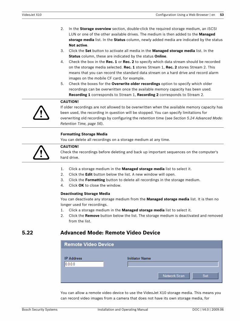
VideoJet X10 Configuration Using a Web Browser | en 53
2. In the Storage overview section, double-click the required storage medium, an iSCSI LUN or one of the other available drives. The medium is then added to the Managed storage media list. In the Status column, newly added media are indicated by the status Not active.
3. Click the Set button to activate all media in the Managed storage media list. In the Status column, these are indicated by the status Online.
4. Check the box in the Rec. 1 or Rec. 2 to specify which data stream should be recorded on the storage media selected. Rec. 1 stores Stream 1, Rec. 2 stores Stream 2. This means that you can record the standard data stream on a hard drive and record alarm images on the mobile CF card, for example.
5. Check the boxes for the Overwrite older recordings option to specify which older recordings can be overwritten once the available memory capacity has been used. Recording 1 corresponds to Stream 1, Recording 2 corresponds to Stream 2.
Formatting Storage MediaYou can delete all recordings on a storage medium at any time.
1. Click a storage medium in the Managed storage media list to select it.2. Click the Edit button below the list. A new window will open.3. Click the Formatting button to delete all recordings in the storage medium.4. Click OK to close the window.
Deactivating Storage MediaYou can deactivate any storage medium from the Managed storage media list. It is then no longer used for recordings.1. Click a storage medium in the Managed storage media list to select it.2. Click the Remove button below the list. The storage medium is deactivated and removed
from the list.
5.22 Advanced Mode: Remote Video Device
You can allow a remote video device to use the VideoJet X10 storage media. This means you can record video images from a camera that does not have its own storage media, for
!CAUTION! If older recordings are not allowed to be overwritten when the available memory capacity has been used, the recording in question will be stopped. You can specify limitations for overwriting old recordings by configuring the retention time (see Section 5.24 Advanced Mode: Retention Time, page 56).
!CAUTION! Check the recordings before deleting and back up important sequences on the computer's hard drive.
Bosch Security Systems Installation and Operating Manual DOC | V4.0 | 2009.06
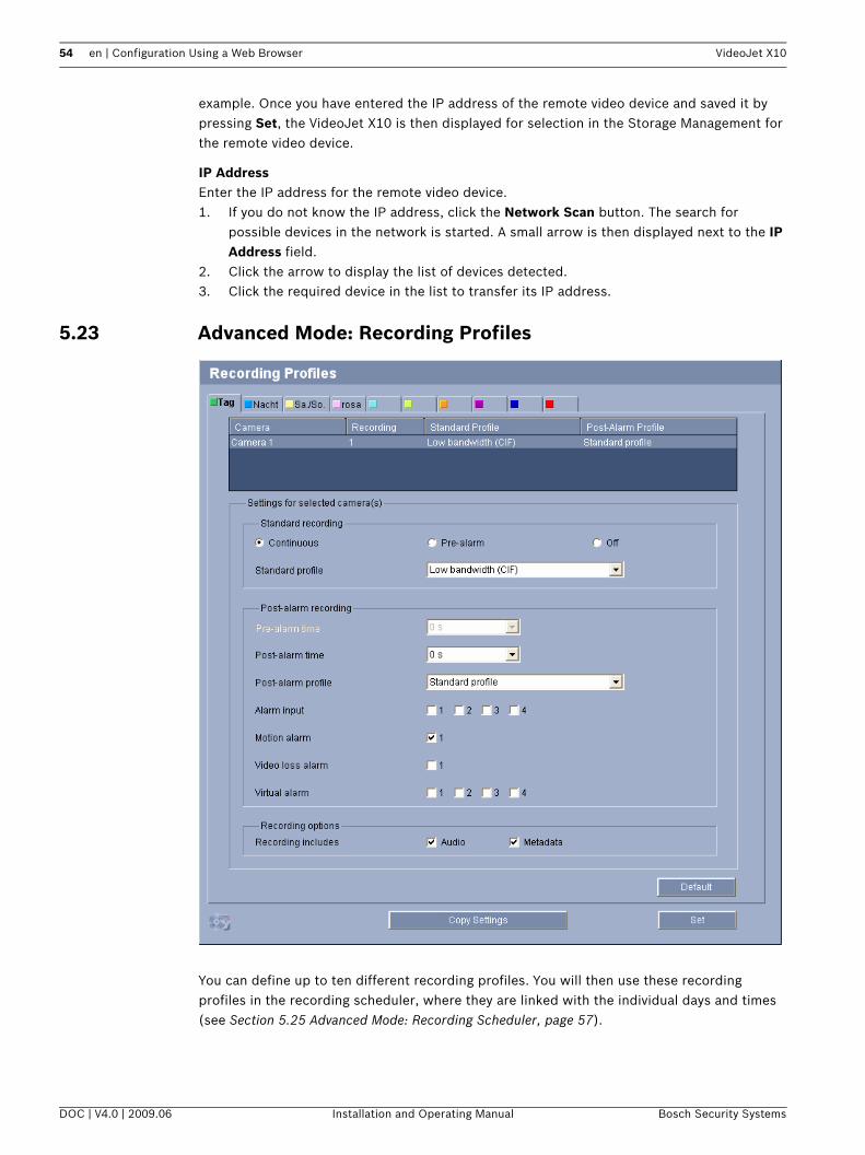
54 en | Configuration Using a Web Browser VideoJet X10
example. Once you have entered the IP address of the remote video device and saved it by pressing Set, the VideoJet X10 is then displayed for selection in the Storage Management for the remote video device.
IP AddressEnter the IP address for the remote video device.1. If you do not know the IP address, click the Network Scan button. The search for
possible devices in the network is started. A small arrow is then displayed next to the IP Address field.
2. Click the arrow to display the list of devices detected.3. Click the required device in the list to transfer its IP address.
5.23 Advanced Mode: Recording Profiles
You can define up to ten different recording profiles. You will then use these recording profiles in the recording scheduler, where they are linked with the individual days and times (see Section 5.25 Advanced Mode: Recording Scheduler, page 57).
DOC | V4.0 | 2009.06 Installation and Operating Manual Bosch Security Systems

VideoJet X10 Configuration Using a Web Browser | en 55
1. Click one of the tabs to edit the corresponding profile.2. If necessary, click the Default button to return all settings to their default values.3. Click the Copy Settings button if you want to copy the currently visible settings to other
profiles. A new window will open and you can select the profiles in which you want to copy the settings.
4. For each profile, click the Set button to save the settings in the unit.
Standard recordingHere you can select the mode for standard recordings. If you select Continuous, the recording proceeds continuously. If the maximum memory capacity is reached, older recordings will automatically be overwritten. If you select the Pre-alarm option, recording will only take place in the pre-alarm time, during the alarm and during the set post-alarm time.If you select Off, no automatic recording takes place.
Standard profileFrom this field, you can select the encoder profile to be used for recording (see Section 5.19 Advanced Mode: Encoder Profile, page 47).
Pre-alarm timeYou can select the required pre-alarm time from the list field.
Post-alarm timeYou can select the required post-alarm time from the list field.
Post-alarm profileYou can select the encoder profile to be used for recording during the post-alarm time (see Section 5.19 Advanced Mode: Encoder Profile, page 47).The Standard profile option adopts the selection at the top of the page.
Alarm input / Motion alarm / Video loss alarmHere you can select the alarm sensor that is to trigger a recording.
iNOTICE! You can change or add to the recording profile description on the tabs on the Recording Scheduler page (see Section Time periods, page 58).
!CAUTION! You can specify limitations for overwriting older recordings in Continuous mode by configuring the retention time (see Section 5.24 Advanced Mode: Retention Time, page 56).
iNOTICE! The recording profile can deviate from the standard setting Active profile and is only used during an active recording.
i
NOTICE! The motion alarm is configured and activated on the VCA page (see Section 5.31 Advanced Mode: VCA Event Triggered, page 69).The alarm inputs are configured and activated on the Alarm Inputs page (see Section 5.35 Advanced Mode: Alarm Inputs, page 74).The numbering of the checkboxes for the alarm inputs corresponds to the labeling of the alarm inputs on the VideoJet X10.
Bosch Security Systems Installation and Operating Manual DOC | V4.0 | 2009.06
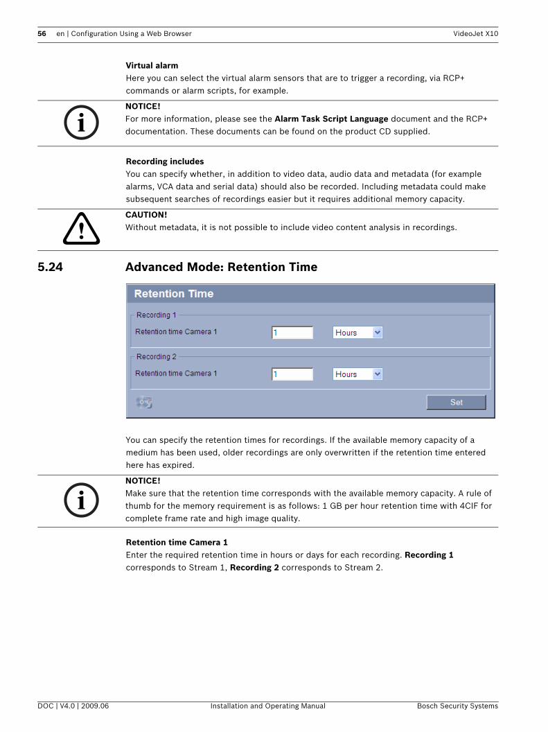
56 en | Configuration Using a Web Browser VideoJet X10
Virtual alarmHere you can select the virtual alarm sensors that are to trigger a recording, via RCP+ commands or alarm scripts, for example.
Recording includesYou can specify whether, in addition to video data, audio data and metadata (for example alarms, VCA data and serial data) should also be recorded. Including metadata could make subsequent searches of recordings easier but it requires additional memory capacity.
5.24 Advanced Mode: Retention Time
You can specify the retention times for recordings. If the available memory capacity of a medium has been used, older recordings are only overwritten if the retention time entered here has expired.
Retention time Camera 1Enter the required retention time in hours or days for each recording. Recording 1 corresponds to Stream 1, Recording 2 corresponds to Stream 2.
iNOTICE! For more information, please see the Alarm Task Script Language document and the RCP+ documentation. These documents can be found on the product CD supplied.
!CAUTION! Without metadata, it is not possible to include video content analysis in recordings.
iNOTICE! Make sure that the retention time corresponds with the available memory capacity. A rule of thumb for the memory requirement is as follows: 1 GB per hour retention time with 4CIF for complete frame rate and high image quality.
DOC | V4.0 | 2009.06 Installation and Operating Manual Bosch Security Systems

VideoJet X10 Configuration Using a Web Browser | en 57
5.25 Advanced Mode: Recording Scheduler
The recording scheduler allows you to link the created recording profiles with the days and times at which the camera's images are to be recorded in the event of an alarm.You can link any number of 15-minute intervals with the recording profiles for each day of the week. Moving the mouse cursor over the table displays the time below it. This aids orientation.In addition to the normal weekdays, you can define holidays that are not in the standard weekly schedule on which recordings are to apply. This allows you to apply a schedule for Sundays to other days with dates that fall on varying weekdays.1. Click the profile you want to link in the Time periods field.2. Click in a field in the table, hold down the mouse button and drag the cursor over all the
periods to be assigned to the selected profile.3. Use the right mouse button to deselect any of the intervals.4. Click the Select All button to link all time intervals to the selected profile.5. Click the Clear All button to deselect all of the intervals.6. When you are finished, click the Set button to save the settings in the unit.
Bosch Security Systems Installation and Operating Manual DOC | V4.0 | 2009.06

58 en | Configuration Using a Web Browser VideoJet X10
HolidaysYou can define holidays that are not in the standard weekly schedule on which recordings are to apply. This allows you to apply a schedule for Sundays to other days with dates that fall on varying weekdays.1. Click the Holidays tab. Any days that have already been selected will be shown in the
table.2. Click the Add button. A new window will open.3. Select the desired date from the calendar. You can select several consecutive calendar
days by holding down the mouse button. These will later be displayed as a single entry in the table.
4. Click OK to accept the selection. The window will close.5. Assign the individual holidays to the recording profiles, as described above.
Deleting HolidaysYou can delete holidays you have defined yourself at any time.1. Click the Delete button. A new window will open.2. Click the date you wish to delete.3. Click OK. The item will be deleted from the table and the window will close.4. The process must be repeated for deleting additional days.
Time periodsYou can change the names of the recording profiles.1. Click a profile and then the Rename button.2. Enter your chosen name and then click the Rename button again.
Activating the RecordingAfter completing configuration you must activate the recording scheduler and start the recording. Once recording is underway, the Recording Profiles and Recording Scheduler pages are deactivated and the configuration cannot be modified.You can stop the recording activity at any time and modify the settings.1. Click the Start button to activate the recording scheduler.2. Click the Stop button to deactivate the recording scheduler. Running recordings are
interrupted and the configuration can be changed.
Recording statusThe graphic indicates the recording activity of the VideoJet X10. You will see an animated graphic while recording is taking place.
DOC | V4.0 | 2009.06 Installation and Operating Manual Bosch Security Systems

VideoJet X10 Configuration Using a Web Browser | en 59
5.26 Advanced Mode: Recording Status
Certain details on the recording status are displayed here for information purposes. You cannot change any of these settings.
5.27 Advanced Mode: Alarm Connections
You can select how the VideoJet X10 responds to an alarm. In the event of an alarm, the unit can automatically connect to a pre-defined IP address. You can enter up to ten IP addresses to which the VideoJet X10 will connect in sequence in the event of an alarm, until a connection is made.
Connect on alarmSelect On so that the VideoJet X10 automatically connects to a predefined IP address in the event of an alarm.
Bosch Security Systems Installation and Operating Manual DOC | V4.0 | 2009.06

60 en | Configuration Using a Web Browser VideoJet X10
By setting Follows input 1 the unit maintains the connection that has been automatically established for as long as an alarm exists on alarm input 1.
Number of destination IP addressSpecify the numbers of the IP addresses to be contacted in the event of an alarm. The unit contacts the remote stations one after the other in the numbered sequence until a connection is made.
Destination IP addressFor each number, enter the corresponding IP address for the desired remote station.
Destination passwordIf the remote station is password protected, enter the password here.In this page, you can save a maximum of ten destination IP addresses and hence up to ten passwords for connecting to remote stations. If connections to more than ten remote stations are to be possible, for example when initiating connections via higher-ranking systems such as VIDOS or Bosch Video Management System, you can store a general password here. The VideoJet X10 can use this general password to connect to all remote stations protected with the same password. In this case, proceed as follows:1. Select 10 from the Number of destination IP address list field.2. Enter the address 0.0.0.0 in the Destination IP address field.3. Enter your chosen password in the Destination password field.4. Define this password as the user password for all remote stations to which a connection
is to be possible.
Video transmissionIf the unit is operated behind a firewall, TCP (HTTP port) should be selected as the transfer protocol. For use in a local network, select UDP.
Remote portDepending on the network configuration, select a browser port here. The ports for HTTPS connections will be available only if the On option is selected in the SSL encryption parameter.
Video outputIf you know which unit is being used as the receiver, you can select the analog video output to which the signal should be switched. If the destination unit is unknown, it is advisable to select the First available option. In this case, the image is placed on the first free video
iNOTICE! In the default setting, Stream 2 is transmitted for alarm connections. Bear this fact in mind when assigning the profile (see Section 5.19 Advanced Mode: Encoder Profile, page 47).
iNOTICE! If you enter the destination IP address 0.0.0.0 for destination 10, this VideoJet X10 address will no longer be used for the tenth attempt at automatic connection in the event of an alarm. The parameter is then used only to save the general password.
!CAUTION! Please note that in some circumstances, a larger bandwidth must be available on the network for additional video images in the event of an alarm, in case Multicast operation is not possible. To enable Multicast operation, select the UDP option for the Video transmission parameter here and on the Network page (see Section Video transmission, page 78).
DOC | V4.0 | 2009.06 Installation and Operating Manual Bosch Security Systems

VideoJet X10 Configuration Using a Web Browser | en 61
output. This is an output on which there is no signal. The connected monitor only displays images when an alarm is triggered. If you select a particular video output and a split image is set for this output on the receiver, you can also select from Decoder the decoder in the receiver that is to be used to display the alarm image.
DecoderSelect a decoder of the receiver to display the alarm image. The decoder selected has an impact on the position of the image in a split screen. For example, you can specify via a VIP XD that the upper-right quadrant should be used to display the alarm image by selecting decoder 2.
SSL encryptionThe data for the connection, for example the password, can be securely transmitted with SSL encryption. If you have selected the On option, only encrypted ports are offered in the Remote port parameter.
You can activate and configure encryption of the media data (video, audio and metadata) on the Encryption page (see Section 5.42 Advanced Mode: Encryption, page 84).
Auto-connectSelect the On option to automatically re-establish a connection to one of the previously specified IP addresses after each reboot, after a connection breakdown or after a network failure.
AudioSelect the On option if you wish to additionally transmit a standalone G.711 encoded audio stream with alarm connections.
iNOTICE! Refer to the destination unit documentation concerning image display options and available video outputs.
iNOTICE! Please note that the SSL encryption must be activated and configured at both ends of a connection. This requires the appropriate certificates to be uploaded onto the VideoJet X10 (see Section Maintenance log, page 85).
iNOTICE! In the default setting, Stream 2 is transmitted for automatic connections. Bear this fact in mind when assigning the profile (see Section 5.19 Advanced Mode: Encoder Profile, page 47).
Bosch Security Systems Installation and Operating Manual DOC | V4.0 | 2009.06

62 en | Configuration Using a Web Browser VideoJet X10
5.28 Advanced Mode: VCA
The VideoJet X10 contains an integrated video content analysis (VCA), which can detect and analyze changes in the signal on the basis of image processing. Such changes can be due to movements in the camera's field of view.You can select various VCA configurations and adapt these to your application as required. The Silent MOTION+ configuration is active by default. In this configuration, metadata is created to facilitate searches of recordings; however, no alarm is triggered.
1. Select a VCA configuration and make the required settings.2. If necessary, click the Default button to return all settings to their default values.
DOC | V4.0 | 2009.06 Installation and Operating Manual Bosch Security Systems

VideoJet X10 Configuration Using a Web Browser | en 63
5.29 Advanced Mode: VCA Profiles
You can configure two profiles with different VCA configurations. You can save profiles on your computer's hard drive and load saved profiles from there. This can be useful if you want to test a number of different configurations. Save a functioning configuration and test new settings. You can use the saved configuration to restore the original settings at any time.
1. Select a VCA profile and enter the required settings.2. If necessary, click the Default button to return all settings to their default values.
iNOTICE! If computing power becomes short, the highest priority is always the live images and recordings. This can lead to impairment of the video content analysis. You should therefore observe the processor load and optimize the encoder settings or the video content analysis settings as necessary (see Section 8.6 Network Connection, page 108).
Bosch Security Systems Installation and Operating Manual DOC | V4.0 | 2009.06

64 en | Configuration Using a Web Browser VideoJet X10
3. Click the Save... button to save the profile settings to another file. A new window is opened, in which you can specify where you want to save the file and what name you want to save it under.
4. Click the Load... button to load a saved profile. A new window opens in which you can select the profile file and specify where to save the file.
VCA configurationSelect one of the profiles here to activate it or edit it. You can rename the profile.1. To rename the file, click the icon to the right of the list field and enter the new profile
name in the field.2. Click the icon again. The new profile name is saved.
Alarm statusThe alarm status is displayed here for information purposes. This means you can check the effects of your settings immediately.
Analysis typeSelect the required analysis algorithm. By default, only MOTION+ is available – this offers a motion detector and essential recognition of tampering.
Metadata is always created for a video content analysis, unless this was explicitly excluded. Depending on the analysis type selected and the relevant configuration, additional information overlays the video image in the preview window next to the parameter settings. With the MOTION+ analysis type, for example, the sensor fields in which motion is recorded will be marked with rectangles.
Motion detector (MOTION+ only)For the detector to function, the following conditions must be met:– Analysis must be activated.– At least one sensor field must be activated.– The individual parameters must be configured to suit the operating environment and the
desired responses.– The sensitivity must be set to a value greater than zero.
iNOTICE! Additional analysis algorithms with comprehensive functions such as IVMD and IVA are available from Bosch Security Systems.If you select one of these algorithms, you can set the corresponding parameters here directly. You can find information on this in the relevant documents on the product CD supplied.
iNOTICE! On the LIVEPAGE Functions page, you can also enable additional information overlays for the LIVEPAGE (see Section 5.15 Advanced Mode: LIVEPAGE Functions, page 43).
!
CAUTION! Reflections of light (off glass surfaces, etc.), switching lights on or off or changes in the light level caused by cloud movement on a sunny day can trigger unintended responses from the motion detector and generate false alarms. Run a series of tests at different times of the day and night to ensure that the video sensor is operating as intended.For indoor surveillance, ensure constant lighting of the areas during the day and at night.
DOC | V4.0 | 2009.06 Installation and Operating Manual Bosch Security Systems
VideoJet X10 Configuration Using a Web Browser | en 65
Sensitivity (MOTION+ only)The basic sensitivity of the motion detector can be adjusted for the environmental conditions to which the camera is subject. The sensor reacts to variations in the brightness of the video image. The darker the observation area, the higher the value that must be selected.
Minimum object size (MOTION+ only)You can specify the number of sensor fields that a moving object must cover to generate an alarm. This is to prevent objects that are too small from triggering an alarm.A minimum value of 4 is recommended. This value corresponds to four sensor fields.
Select Area (MOTION+ only)The areas of the image to be monitored by the motion detector can be selected. The video image is subdivided into 858 square fields. Each of these fields can be activated or deactivated individually. If you wish to exclude particular regions of the camera's field of view from monitoring due to continuous movement (by a tree in the wind, etc.), the relevant fields can be deactivated.1. Click Select Area to configure the sensor fields. A new window will open.2. If necessary, click Clear All first to clear the current selection (fields marked yellow).3. Left-click the fields to be activated. Activated fields are marked yellow.4. If necessary, click Select All to select the entire video frame for monitoring.5. Right-click any fields you wish to deactivate.6. Click OK to save the configuration.7. Click the close button X in the window title bar to close the window without saving the
changes.
Tamper detectionYou can reveal the tampering of cameras and video cables by means of various options. Run a series of tests at different times of the day and night to ensure that the video sensor is operating as intended.
Sensitivity
The basic sensitivity of the tamper detection can be adjusted for the environmental conditions to which the camera is subject.The algorithm reacts to the differences between the reference image and the current video image. The darker the observation area, the higher the value that must be selected.
Trigger delay (s)You can set delayed alarm triggering. The alarm is only triggered after a set time interval in seconds has elapsed and then only if the triggering condition still exists. If the original condition has been restored before this time interval elapses, the alarm is not triggered. This allows you to avoid false alarms triggered by short-term changes, for example cleaning activities in the direct field of vision of the camera.
iNOTICE! The options for tamper detection can only be set for fixed cameras. Dome cameras or other motorized cameras cannot be protected in this manner as the movement of the camera itself causes changes in the video image that are too great.
iNOTICE! This and the following parameter are only accessible if the reference check is activated.
Bosch Security Systems Installation and Operating Manual DOC | V4.0 | 2009.06

66 en | Configuration Using a Web Browser VideoJet X10
Global changeYou can set how large the global change in the video image must be for an alarm to be triggered. This setting is independent of the sensor fields selected under Select Area. Set a high value if fewer sensor fields need to change to trigger an alarm. With a low value, it is necessary for changes to occur simultaneously in a large number of sensor fields to trigger an alarm.This option allows you to detect, independently of motion alarms, manipulation of the orientation or location of a camera resulting from turning the camera mount bracket, for instance.
Global changeActivate this function if the global change, as set with the Global change slide control, should trigger an alarm.
Scene too brightActivate this function if tampering associated with exposure to extreme light (for instance, shining a flashlight directly on the lens) should trigger an alarm. The average brightness of the scene provides a basis for recognition.
Scene too darkActivate this function if tampering associated with covering the lens (for instance, by spraying paint on it) should trigger an alarm. The average brightness of the scene provides a basis for recognition.
Scene too noisyActivate this function if tampering associated with EMC interference (noisy scene as the result of a strong interference signal in the vicinity of the video lines), as an example, should trigger an alarm.
Reference checkYou can save a reference image that is continuously compared with the current video image. If the current video image in the marked areas differs from the reference image, an alarm is triggered. This allows you to detect tampering that would otherwise not be detected, for example if the camera is turned.1. Click Reference to save the currently visible video image as a reference.2. Click Select Area and select the areas in the reference image that are to be monitored.3. Check the box Reference check to activate on-going matching. The stored reference
image is displayed in black and white below the current video image, and the selected areas are marked in yellow.
4. Select the Disappearing edges or Appearing edges option to specify the reference check once again.
Select AreaYou can select the image areas in the reference image that are to be monitored. The video image is subdivided into 858 square fields. Each of these fields can be activated or deactivated individually.
1. Click Select Area to configure the sensor fields. A new window will open.2. If necessary, click Clear All first to clear the current selection (fields marked yellow).
iNOTICE! Select only those areas for reference monitoring in which no movement takes place and that are always evenly lit, as false alarms could otherwise be triggered.
DOC | V4.0 | 2009.06 Installation and Operating Manual Bosch Security Systems

VideoJet X10 Configuration Using a Web Browser | en 67
3. Left-click the fields to be activated. Activated fields are marked yellow.4. If necessary, click Select All to select the entire video frame for monitoring.5. Right-click any fields you wish to deactivate.6. Click OK to save the configuration.7. Click the close button X in the window title bar to close the window without saving the
changes.
5.30 Advanced Mode: VCA Scheduled
This configuration allows you to link the created VCA profile with the days and times at which the video content analysis is to be active.You can link any number of 15-minute intervals with the VCA profiles for each day of the week. Moving the mouse cursor over the table displays the time below it. This aids orientation.In addition to the normal weekdays, you can define holidays that are not in the standard weekly schedule on which recordings are to apply. This allows you to apply a schedule for Sundays to other days with dates that fall on varying weekdays.
Bosch Security Systems Installation and Operating Manual DOC | V4.0 | 2009.06

68 en | Configuration Using a Web Browser VideoJet X10
1. Click the profile you want to link in the Time periods field.2. Click in a field in the table, hold down the mouse button and drag the cursor over all the
periods to be assigned to the selected profile.3. Use the right mouse button to deselect any of the intervals.4. Click the Select All button to link all time intervals to the selected profile.5. Click the Clear All button to deselect all of the intervals.6. When you are finished, click the Set button to save the settings in the unit.
HolidaysYou can define holidays on which a profile should be active that are different to the standard weekly schedule. This allows you to apply a schedule for Sundays to other days with dates that fall on varying weekdays.1. Click the Holidays tab. Any days that have already been selected will be shown in the
table.2. Click the Add button. A new window will open.3. Select the desired date from the calendar. You can select several consecutive calendar
days by holding down the mouse button. These will later be displayed as a single entry in the table.
4. Click OK to accept the selection. The window will close.5. Assign the individual holidays to the VCA profiles, as described above.
Deleting HolidaysYou can delete holidays you have defined yourself at any time.1. Click the Delete button. A new window will open.2. Click the date you wish to delete.3. Click OK. The item will be deleted from the table and the window will close.4. The process must be repeated for deleting additional days.
DOC | V4.0 | 2009.06 Installation and Operating Manual Bosch Security Systems

VideoJet X10 Configuration Using a Web Browser | en 69
5.31 Advanced Mode: VCA Event Triggered
This configuration allows you stipulate that the video content analysis is only to be activated when triggered by an event. As long as no trigger is activated, the Silent MOTION+ configuration in which metadata is created is active; this metadata facilitates searches of recordings, but does not trigger an alarm.
TriggerYou can select one of the physical alarms on the device's alarm inputs or one of the virtual alarms as a trigger. A virtual alarm is created using software, with RCP+ commands or alarm scripts, for example.
iNOTICE! For more information, please see the Alarm Task Script Language document and the RCP+ documentation. You can find these documents on the product CD supplied (see Section 3.1 Scope of Delivery, page 11).
Bosch Security Systems Installation and Operating Manual DOC | V4.0 | 2009.06

70 en | Configuration Using a Web Browser VideoJet X10
Trigger activeSelect the VCA configuration here that is to be enabled via an active trigger. A green check mark to the right of the list field indicates that the trigger is active.
Trigger inactiveSelect the VCA configuration here that is to be activated if the trigger is not active. A green check mark to the right of the list field indicates that the trigger is inactive.
Delay (s)Select the delay period here for the reaction of the video content analysis to trigger signals. A delay period may be useful in avoiding false alarms or frequent triggering, for example. During the delay period, the Silent MOTION+ configuration is always enabled.
5.32 Advanced Mode: Audio Alarm
The VideoJet X10 can create alarms on the basis of audio signals. You can configure signal strengths and frequency ranges in such a way that false alarms, for example due to machine noise or background noise, are avoided.
Audio alarmSelect On if you want the device to generate audio alarms.
iNOTICE! First set up normal audio transmission before you configure the audio alarm here (see Section 5.20 Advanced Mode: Audio, page 50).
DOC | V4.0 | 2009.06 Installation and Operating Manual Bosch Security Systems
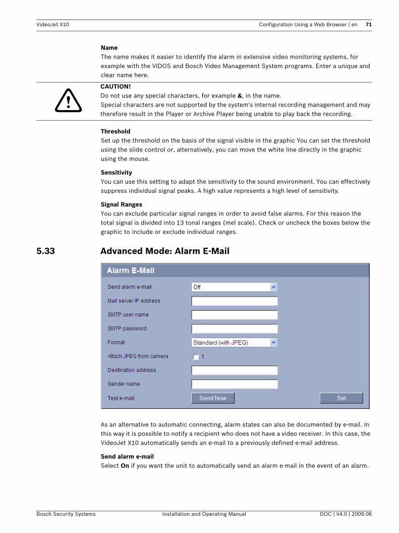
VideoJet X10 Configuration Using a Web Browser | en 71
NameThe name makes it easier to identify the alarm in extensive video monitoring systems, for example with the VIDOS and Bosch Video Management System programs. Enter a unique and clear name here.
ThresholdSet up the threshold on the basis of the signal visible in the graphic You can set the threshold using the slide control or, alternatively, you can move the white line directly in the graphic using the mouse.
SensitivityYou can use this setting to adapt the sensitivity to the sound environment. You can effectively suppress individual signal peaks. A high value represents a high level of sensitivity.
Signal RangesYou can exclude particular signal ranges in order to avoid false alarms. For this reason the total signal is divided into 13 tonal ranges (mel scale). Check or uncheck the boxes below the graphic to include or exclude individual ranges.
5.33 Advanced Mode: Alarm E-Mail
As an alternative to automatic connecting, alarm states can also be documented by e-mail. In this way it is possible to notify a recipient who does not have a video receiver. In this case, the VideoJet X10 automatically sends an e-mail to a previously defined e-mail address.
Send alarm e-mailSelect On if you want the unit to automatically send an alarm e-mail in the event of an alarm.
!CAUTION! Do not use any special characters, for example &, in the name.Special characters are not supported by the system's internal recording management and may therefore result in the Player or Archive Player being unable to play back the recording.
Bosch Security Systems Installation and Operating Manual DOC | V4.0 | 2009.06
72 en | Configuration Using a Web Browser VideoJet X10
Mail server IP addressEnter the IP address of a mail server that operates on the SMTP standard (Simple Mail Transfer Protocol). Outgoing e-mails are sent to the mail server via the address you entered. Otherwise leave the box blank (0.0.0.0).
SMTP user nameEnter a registered user name for the chosen mailserver here.
SMTP passwordEnter the required password for the registered user name here.
FormatYou can select the data format of the alarm message.– Standard (with JPEG)
E-mail with attached JPEG image file.– SMS
E-mail in SMS format to an e-mail-to-SMS gateway (for example to send an alarm by cellphone) without an image attachment.
Attach JPEG from cameraClick the checkbox to specify that JPEG images are sent from the camera. An enabled video input is indicated by a check mark.
Destination addressEnter the e-mail address for alarm e-mails here. The maximum address length is 49 characters.
Sender nameEnter a unique name for the e-mail sender, for example the location of the unit. This will make it easier to identify the origin of the e-mail.
Test e-mailYou can test the e-mail function by clicking the Send Now button. An alarm e-mail is immediately created and sent.
!CAUTION! When a cellphone is used as the receiver, make sure to activate the e-mail or SMS function, depending on the format, so that these messages can be received.You can obtain information on operating your cellphone from your cellphone provider.
DOC | V4.0 | 2009.06 Installation and Operating Manual Bosch Security Systems

VideoJet X10 Configuration Using a Web Browser | en 73
5.34 Advanced Mode: Alarm Task Editor
As an alternative to the alarm settings on the various alarm pages, you can enter your desired alarm functions in script form here. This will overwrite all settings and entries on the other alarm pages.1. Click the Examples link under the Alarm Task Editor field to see some script examples. A
new window will open.2. Enter new scripts in the Alarm Task Editor field or change existing scripts in line with
your requirements.3. When you are finished, click the Set button to transmit the scripts to the unit. If the
transfer was successful, the message Script successfully parsed is displayed over the text field. If it was not successful, an error message will be displayed with further information.
!
CAUTION! Editing scripts on this page overwrites all settings and entries on the other alarm pages. This procedure cannot be reversed.In order to edit this page, you must have programming knowledge and be familiar with the information in the Alarm Task Script Language document. You can find the document on the product CD supplied (see Section 3.1 Scope of Delivery, page 11).
Bosch Security Systems Installation and Operating Manual DOC | V4.0 | 2009.06

74 en | Configuration Using a Web Browser VideoJet X10
5.35 Advanced Mode: Alarm Inputs
You can configure the alarm inputs of the VideoJet X10.
Alarm inputSelect Active high if the alarm is to be triggered when the contact closes. Select Active low if the alarm is to be triggered when the contact opens.
NameYou can enter a name for each alarm input, which is then displayed below the icon for the alarm input on the LIVEPAGE if configured correctly (see Section 5.15 Advanced Mode: LIVEPAGE Functions, page 43).
5.36 Advanced Mode: Relay
You can configure the switching behavior of the relay outputs. For each relay, you can specify an open switch relay (normally closed contact) or a closed switch relay (normally open contact).You can also specify whether an output should operate as a bistable or monostable relay. In bistable mode, the triggered state of the relay is maintained. In monostable mode, you can set the time after which the relay will return to the idle state. You can select different events that automatically activate an output. It is possible, for example, to turn on a floodlight by triggering a motion alarm and then turning the light off again when the alarm has stopped.
Idle stateSelect Open if you want the relay to operate as an NO contact, or select Closed if the relay is to operate as an NC contact.
DOC | V4.0 | 2009.06 Installation and Operating Manual Bosch Security Systems

VideoJet X10 Configuration Using a Web Browser | en 75
Operating modeSelect an operating mode for the relay.For example, if you want an alarm-activated lamp to stay on after the alarm ends, select Bistable. If you wish an alarm-activated siren to sound for ten seconds, for example, select 10 s.
Relay followsIf required, select a specific event that will trigger the relay. The following events are possible triggers:– Off
Relay is not triggered by events– Connection
Trigger whenever a connection is made– Video alarm
Trigger by interruption of the video signal– Motion alarm
Trigger by motion alarm, as configured on the VCA page (see Section 5.31 Advanced Mode: VCA Event Triggered, page 69)
– Local inputTrigger by the corresponding external alarm input
– Remote inputTrigger by remote station's corresponding switching contact (only if a connection exists)
Relay nameYou can assign a name for the relay here. The name is shown on the button next to Trigger relay. The Livepage can also be configured to display the name under the relay icon.
Trigger relayClick the button to trigger the relay manually (for testing or to operate a door opener, for example).
iNOTICE! The numbers in the lists of selectable events relate to the corresponding connections on the unit, Video alarm 1, for example to the Video In connection.
Bosch Security Systems Installation and Operating Manual DOC | V4.0 | 2009.06

76 en | Configuration Using a Web Browser VideoJet X10
5.37 Advanced Mode: COM1
You can configure the serial interface parameters (orange terminal block) to meet your requirements.
Serial port functionSelect a controllable unit from the list. If you wish to use the serial port to transmit transparent data, select Transparent. Select Terminal if you wish to operate the unit from a terminal.
Camera IDIf necessary, enter the ID of the peripheral you wish to control (for example a dome camera or pan/tilt head).
Baud rateSelect the value for the transmission rate in bps.
Data bitsThe number of data bits per character cannot be changed.
Stop bitsSelect the number of stop bits per character.
Parity checkSelect the type of parity check.
Interface modeSelect the desired protocol for the serial interface.
iNOTICE! If the VideoJet X10 is working in multicast mode (see Section 5.40 Advanced Mode: Multicasting, page 81), the first remote location to establish a video connection to the unit is also assigned the transparent data connection. However, after about 15 seconds of inactivity the data connection is automatically terminated and another remote location can exchange transparent data with the unit.
iNOTICE! After selecting a unit, the remaining parameters in the window are set automatically and should not be changed.
DOC | V4.0 | 2009.06 Installation and Operating Manual Bosch Security Systems

VideoJet X10 Configuration Using a Web Browser | en 77
5.38 Advanced Mode: Network
The settings on this page are used to integrate the VideoJet X10 into an existing network.Some changes only take effect after the unit is rebooted. In this case, the Set button changes to Set and Reboot.1. Make the desired changes.2. Click the Set and Reboot button. The VideoJet X10 is rebooted and the changed settings
are activated.
Bosch Security Systems Installation and Operating Manual DOC | V4.0 | 2009.06

78 en | Configuration Using a Web Browser VideoJet X10
Automatic IP assignmentIf a DHCP server is employed in the network for the dynamic assignment of IP addresses, you can activate acceptance of IP addresses automatically assigned to the VideoJet X10.Certain applications (VIDOS, Bosch Video Management System, Archive Player, Configuration Manager) use the IP address for the unique assignment of the unit. If you use these applications, the DHCP server must support the fixed assignment between IP address and MAC address, and must be appropriately set up so that, once an IP address is assigned, it is retained each time the system is rebooted.
IP addressEnter the desired IP address for the VideoJet X10 in this field. The IP address must be valid for the network.
Subnet maskEnter the appropriate subnet mask for the selected IP address here.
Gateway addressIf you want the unit to establish a connection to a remote location in a different subnet, enter the IP address of the gateway here. Otherwise leave the box blank (0.0.0.0).
DNS server addressThe unit can use a DNS server to trigger an address specified as a name. Enter the IP address of the DNS server here.
Video transmissionIf the unit is operated behind a firewall, TCP (HTTP port) should be selected as the transfer protocol. For use in a local network, select UDP.
HTTP browser portSelect a different HTTP browser port from the list if required. The default HTTP port is 80. If you want to allow only secure connections via HTTPS, you must deactivate the HTTP port. In this case, select Off.
HTTPS browser portIf you wish to allow browser access on the network via a secure connection, select an HTTPS browser port from the list if necessary. The default HTTPS port is 443. Select the Off option to deactivate HTTPS ports; only unsecured connections will now be possible.The VideoJet X10 uses the TLS 1.0 encryption protocol. You may have to activate this protocol via your browser configuration. You must also activate the protocol for the Java applications (via the Java control panel in the Windows control panel).
!CAUTION! If you change the IP address, subnet mask or gateway address, the VideoJet X10 is only available under the new addresses after the reboot.
!CAUTION! Multicast operation is only possible with the UDP protocol. The TCP protocol does not support multicast connections.The MTU value in UDP mode is 1,514 bytes.
DOC | V4.0 | 2009.06 Installation and Operating Manual Bosch Security Systems

VideoJet X10 Configuration Using a Web Browser | en 79
You can activate and configure encryption of the media data (video, audio and metadata) on the Encryption page (see Section 5.42 Advanced Mode: Encryption, page 84).
RCP+ port 1756To exchange connection data, you can activate the unsecured RCP+ port 1756. If you want connection data to be transmitted only when encrypted, select the Off option to deactivate the port.
Telnet supportIf you want to allow only secure connections with encrypted data transmission, you must select the Off option to deactivate Telnet support. The unit will then no longer be accessible using the Telnet protocol.
Interface mode ETH 1If necessary, select the Ethernet link type for interface ETH 1. Depending on the unit connected, it may be necessary to select a special operation type.
Interface mode ETH 2If necessary, select the Ethernet link type for interface ETH 2. Depending on the unit connected, it may be necessary to select a special operation type.
Network MSS (Byte)You can set the maximum segment size for the IP packet's user data. This gives you the option to adjust the size of the data packets to the network environment and to optimize data transmission. Please comply with the MTU value of 1,514 bytes in UDP mode.
iSCSI MSS (Byte)You can specify a higher MSS value for a connection to the iSCSI system than for the other data traffic via the network. The potential value depends on the network structure. A higher value is only useful if the iSCSI system is located in the same subnet as the VideoJet X10.
Enable DynDNSDynDNS.org is a DNS hosting service that stores IP addresses in a database ready for use. It allows you to select the VideoJet X10 via the Internet using a host name, without having to know the current IP address of the unit. You can enable this service here. To do this, you must have an account with DynDNS.org and you must have registered the required host name for the unit on that site.
Host nameEnter the host name registered on DynDNS.org for the VideoJet X10 here.
User nameEnter the user name you registered at DynDNS.org here.
iNOTICE! If you want to allow only secure connections with SSL encryption, you must select the Off option for each of the parameters HTTP browser port, RCP+ port 1756 and Telnet support. This deactivates all unsecured connections. Connections will then only be possible via the HTTPS port.
iNOTICE! Information about the service, registration process and available host names can be found at DynDNS.org.
Bosch Security Systems Installation and Operating Manual DOC | V4.0 | 2009.06

80 en | Configuration Using a Web Browser VideoJet X10
PasswordEnter the password you registered at DynDNS.org here.
Force registration nowYou can force the registration by transferring the IP address to the DynDNS server. Entries that change frequently are not provided in the Domain Name System. It is a good idea to force the registration when you are setting up the device for the first time. Only use this function when necessary and no more than once a day, to avoid the possibility of being blocked by the service provider. To transfer the IP address of the VideoJet X10, click the Register button.
StatusThe status of the DynDNS function is displayed here for information purposes. You cannot change any of these settings.
5.39 Advanced Mode: Advanced
The settings on this page are used to implement advanced settings for the network.Some changes only take effect after the unit is rebooted. In this case, the Set button changes to Set and Reboot.1. Make the desired changes.2. Click the Set and Reboot button. The VideoJet X10 is rebooted and the changed settings
are activated.
SNMPThe VideoJet X10 supports the SNMP V2 (Simple Network Management Protocol) for managing and monitoring network components, and can send SNMP messages (traps) to IP addresses. The unit supports SNMP MIB II in the unified code. If you wish to send SNMP traps, enter the IP addresses of one or two required target devices here.
DOC | V4.0 | 2009.06 Installation and Operating Manual Bosch Security Systems
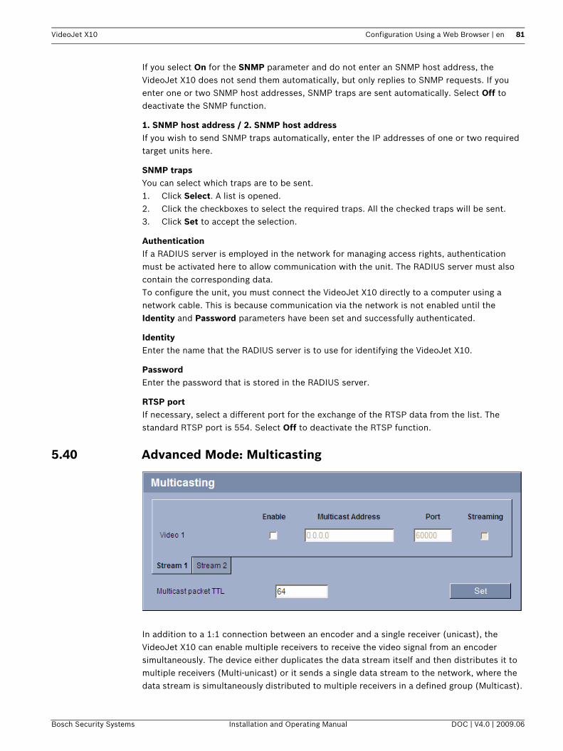
VideoJet X10 Configuration Using a Web Browser | en 81
If you select On for the SNMP parameter and do not enter an SNMP host address, the VideoJet X10 does not send them automatically, but only replies to SNMP requests. If you enter one or two SNMP host addresses, SNMP traps are sent automatically. Select Off to deactivate the SNMP function.
1. SNMP host address / 2. SNMP host addressIf you wish to send SNMP traps automatically, enter the IP addresses of one or two required target units here.
SNMP trapsYou can select which traps are to be sent.1. Click Select. A list is opened.2. Click the checkboxes to select the required traps. All the checked traps will be sent.3. Click Set to accept the selection.
AuthenticationIf a RADIUS server is employed in the network for managing access rights, authentication must be activated here to allow communication with the unit. The RADIUS server must also contain the corresponding data.To configure the unit, you must connect the VideoJet X10 directly to a computer using a network cable. This is because communication via the network is not enabled until the Identity and Password parameters have been set and successfully authenticated.
IdentityEnter the name that the RADIUS server is to use for identifying the VideoJet X10.
PasswordEnter the password that is stored in the RADIUS server.
RTSP portIf necessary, select a different port for the exchange of the RTSP data from the list. The standard RTSP port is 554. Select Off to deactivate the RTSP function.
5.40 Advanced Mode: Multicasting
In addition to a 1:1 connection between an encoder and a single receiver (unicast), the VideoJet X10 can enable multiple receivers to receive the video signal from an encoder simultaneously. The device either duplicates the data stream itself and then distributes it to multiple receivers (Multi-unicast) or it sends a single data stream to the network, where the data stream is simultaneously distributed to multiple receivers in a defined group (Multicast).
Bosch Security Systems Installation and Operating Manual DOC | V4.0 | 2009.06

82 en | Configuration Using a Web Browser VideoJet X10
You can enter a dedicated multicast address and port for each stream. You can switch between the streams by clicking the appropriate tabs.
A special IP address (class D address) must be configured for multicast operation in a multicast-enabled network.The network must support group IP addresses and the Internet Group Management Protocol (IGMP V2). The address range is from 225.0.0.0 to 239.255.255.255.The multicast address can be the same for multiple streams. However, it will be necessary to use a different port in each case so that multiple data streams are not sent simultaneously using the same port and multicast address.
EnableTo enable simultaneous data reception on several receivers you need to activate the multicast function. To do this, check the box. You can then enter the multicast address.
Multicast AddressEnter a valid multicast address for each stream to be operated in multicast mode (duplication of the data streams in the network).With the setting 0.0.0.0 the encoder for the relevant stream operates in multi-unicast mode (copying of data streams in the unit). The VideoJet X10 supports multi-unicast connections for up to five simultaneously connected receivers.
PortAssign a different port to each data stream if there are simultaneous data streams at the same multicast address.Enter the port address of the required stream here.
StreamingClick the checkbox to activate multicast streaming mode for the relevant stream. An enabled stream is indicated by a check mark.For normal multicast operation, streaming is typically not required.
Multicast packet TTLYou can enter a value to specify how long the multicast data packets are active on the network. This value must be greater than one if multicast is to be run via a router.
iNOTICE! Multicast operation requires a multicast-enabled network that uses the UDP and the Internet Group Management IGMP protocols. Other group management protocols are not supported. The TCP protocol does not support multicast connections.
iNOTICE! The settings must be made individually for each stream.
iNOTICE! Duplication of data places a heavy demand on the unit and can lead to impairment of the image quality under certain circumstances.
DOC | V4.0 | 2009.06 Installation and Operating Manual Bosch Security Systems

VideoJet X10 Configuration Using a Web Browser | en 83
5.41 Advanced Mode: JPEG Posting
You can save individual JPEG images on an FTP server at specific intervals. You can then retrieve these images at a later date to reconstruct alarm events if required.
Image sizeSelect the resolution you wish the JPEG images to have:– Small
176 × 144/120 pixels (QCIF)– Medium
352 × 288/240 pixels (CIF)– Large
704 × 576/480 pixels (4CIF)
File nameYou can select how file names will be created for the individual images that are transmitted.– Overwrite
The same file name is always used and any existing file will be overwritten with the current file.
– IncrementA number from 000 to 255 is added to the file name and automatically incremented by 1. When it reaches 255 it starts again from 000.
– Date/time suffixThe date and time are automatically added to the file name. When setting this parameter, ensure that the unit's date and time are always correctly set. Example: the file snap011005_114530.jpg was stored on October 1, 2005 at 11:45 and 30 seconds.
Posting intervalEnter the interval in seconds at which the images will be sent to an FTP server. Enter zero if you do not want any images to be sent.
FTP server IP addressEnter the IP address of the FTP server on which you wish to save the JPEG images.
FTP server loginEnter your login name for the FTP server.
FTP server passwordEnter the password that gives you access to the FTP server.
Bosch Security Systems Installation and Operating Manual DOC | V4.0 | 2009.06

84 en | Configuration Using a Web Browser VideoJet X10
Path on FTP serverEnter the exact path on which you wish to post the images on the FTP server.
5.42 Advanced Mode: EncryptionA special license, with which you will receive a corresponding activation key, is required to encrypt user data. You can enter the activation key to release the function on the Licenses page (see Section 5.44 Advanced Mode: Licenses, page 86).
5.43 Advanced Mode: Maintenance
FirmwareThe VideoJet X10 is designed in such a way that its functions and parameters can be updated with firmware. To do this, transfer the current firmware package to the unit via the selected network. It will then be automatically installed there.In this way, a VideoJet X10 can be serviced and updated remotely without a technician having to change the installation on site.You obtain the current firmware from your customer service or from the download area at www.boschsecurity.com.
1. First store the firmware file on your hard drive.2. Enter the full path of the firmware file in the field or click Browse to locate and select the
file.
iNOTICE! The creation of JPEG images has a lower priority than video encoding and image analysis. Thiscan result in JPEG images being created with a delay of up to several seconds after the triggering event. If reliable, real-time recording of the alarm is required, ensure that the encoder has enough computing power available.
!
CAUTION! Before launching the firmware upload make sure that you have selected the correct upload file. Uploading the wrong files can result in the unit no longer being addressable, in which case you must replace the unit.You should never interrupt the installation of firmware. An interruption can lead to the flash-EPROM being incorrectly programmed. This in turn can result in the unit no longer being addressable, in which case it will have to be replaced. Even changing to another page or closing the browser window leads to an interruption.
DOC | V4.0 | 2009.06 Installation and Operating Manual Bosch Security Systems

VideoJet X10 Configuration Using a Web Browser | en 85
3. Next, click Upload to begin transferring the file to the unit. The progress bar allows you to monitor the transfer.
The new firmware is unpacked and the Flash EPROM is reprogrammed. The time remaining is shown by the message going to reset Reconnecting in ... seconds. The unit reboots automatically once the upload has successfully completed.If the Connect LED lights up red, the upload has failed and must be repeated. To perform the upload you must now switch to a special page:1. In the address bar of your browser, enter /main.htm after the IP address of the
VideoJet X10 (for example 192.168.0.10/main.htm).2. Repeat the upload.
ConfigurationYou can save configuration data for the VideoJet X10 on a computer and then load saved configuration data from a computer to the unit.Upload1. Enter the full path of the file to upload or click Browse to select the required file.2. Make certain that the file to be loaded comes from the same unit type as the unit you
want to configure.3. Next, click Upload to begin transferring the file to the unit. The progress bar allows you
to monitor the transfer.Once the upload is complete, the new configuration is activated. The time remaining is shown by the message going to reset Reconnecting in ... seconds. The unit reboots automatically once the upload has successfully completed.Download1. Click the Download button. A dialog box opens.2. Follow the on-screen instructions to save the current settings.
SSL certificateTo be able to work with an SSL encrypted data connection, both ends of a connection must hold the relevant certificates. You can upload the SSL certificate, comprising one or multiple files, onto the VideoJet X10. If you wish to upload multiple files onto the VideoJet X10, you must select them consecutively.
1. Enter the full path of the file to upload or click Browse to select the required file.2. Next, click Upload to begin transferring the file to the unit.3. Once all files have been successfully uploaded, the unit must be rebooted. In the address
bar of your browser, enter /reset after the IP address of the VideoJet X10 (for example 192.168.0.10/reset).
The new SSL certificate is valid.
Maintenance logYou can download an internal maintenance log from the unit to send it to Customer Service for support purposes. Click Download and select a storage location for the file.
iNOTICE! The certificate must be created in the format *.pem so that it can be accepted by the unit.
Bosch Security Systems Installation and Operating Manual DOC | V4.0 | 2009.06

86 en | Configuration Using a Web Browser VideoJet X10
5.44 Advanced Mode: Licenses
You can enter the activation key to release additional functions or software modules.
5.45 Advanced Mode: System Overview
The data on this page are for information purposes only and cannot be changed. Keep a record of this information in case technical assistance is required.
iNOTICE! The activation key cannot be deactivated again and is not transferable to other units.
iNOTICE! You can select all required text on this page with the mouse and copy it to the clipboard with the [Ctrl]+[C] key combination, for example if you want to send it via e-mail.
DOC | V4.0 | 2009.06 Installation and Operating Manual Bosch Security Systems
VideoJet X10 Configuration Using a Web Browser | en 87
5.46 Function TestThe VideoJet X10 offers a variety of configuration options. You should therefore check that it is functioning correctly after installation and configuration.The function test is the only way to ensure that the VideoJet X10 operates as expected in the event of an alarm. Your check should include the following functions:– Can the VideoJet X10 be called up remotely?– Does the VideoJet X10 transmit all the required data?– Does the VideoJet X10 respond to alarm events as required?– Do the recordings occur as intended?– Is it possible to control peripherals if necessary?
Bosch Security Systems Installation and Operating Manual DOC | V4.0 | 2009.06
88 en | Configuration Using a Web Browser VideoJet X10
DOC | V4.0 | 2009.06 Installation and Operating Manual Bosch Security Systems
VideoJet X10 Operation | en 89
6 Operation
6.1 Operation with Microsoft Internet ExplorerA computer with Microsoft Internet Explorer (version 6.0 or higher) can receive live images from the VideoJet X10, control cameras or other peripherals and replay stored video sequences.
System Requirements– Computer with Windows XP or Windows Vista operating system– Network access (Intranet or Internet)– Microsoft Internet Explorer (version 6.0 or higher)– Screen resolution 1,024 × 768 pixels– 16- or 32-bit color depth– Installed Sun JVM– For playing back recordings: connection to storage medium
Installing MPEG ActiveXSuitable MPEG ActiveX software must be installed on the computer to allow the live video images to be played back. If necessary, you can install the program from the product CD supplied.1. Insert the product CD into the computer's CD-ROM drive. If the CD does not start
automatically, open the root directory of the CD in Windows Explorer and double-click MPEGAx.exe.
2. Follow the on-screen instructions.
i
NOTICE! Also note the information in the System Requirements document on the product CD supplied. If necessary, you can install the required programs and controls from the product CD supplied (see Section 3.1 Scope of Delivery, page 11).The Web browser must be configured to enable Cookies to be set from the IP address of the unit.In Windows Vista, deactivate protected mode on the Security tab under Internet Options.You can find notes on using Microsoft Internet Explorer in the online Help in Internet Explorer.
Bosch Security Systems Installation and Operating Manual DOC | V4.0 | 2009.06
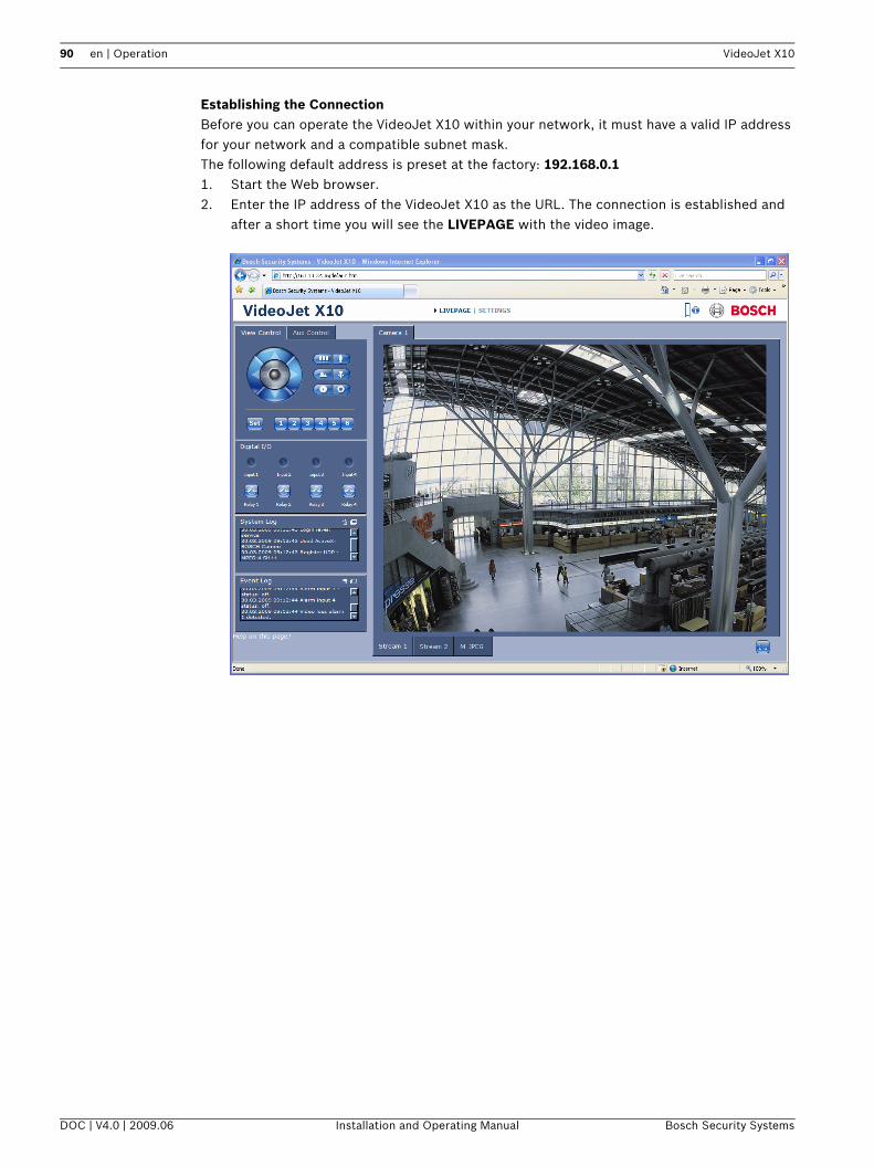
90 en | Operation VideoJet X10
Establishing the ConnectionBefore you can operate the VideoJet X10 within your network, it must have a valid IP address for your network and a compatible subnet mask.The following default address is preset at the factory: 192.168.0.11. Start the Web browser.2. Enter the IP address of the VideoJet X10 as the URL. The connection is established and
after a short time you will see the LIVEPAGE with the video image.
DOC | V4.0 | 2009.06 Installation and Operating Manual Bosch Security Systems

VideoJet X10 Operation | en 91
6.2 The LIVEPAGEOnce the connection is established, the Web browser displays the LIVEPAGE. It shows the live video image on the right of the browser window. Depending on the configuration, various text overlays may be visible on the live video image (see Section 5.13 Advanced Mode: Display Stamping, page 40).Other information may be shown next to live video image on the LIVEPAGE. The display depends on the settings on the LIVEPAGE Functions page (see Section 5.15 Advanced Mode: LIVEPAGE Functions, page 43).
Maximum Number of ConnectionsIf you do not connect, the unit may have reached its maximum number of connections. Depending on the unit and network configuration, each VideoJet X10 can have up to 25 Web browser connections or up to 50 connections via VIDOS or Bosch Video Management System.
Protected VideoJet X10If the VideoJet X10 is password protected against unauthorized access, the Web browser displays a corresponding message and prompts you to enter the password when you attempt to access protected areas.
1. Enter the user name and associated password in the corresponding text fields.2. Click OK. If the password is entered correctly, the Web browser displays the page that
was called up.
Protected NetworkIf a RADIUS server is employed in the network for managing access rights (802.1x authentication), the VideoJet X10 must be configured accordingly, otherwise no communication is possible (see Section Authentication, page 81).
Image SelectionYou can view the image of the camera in different displays.
Click one of the tabs Stream 1, Stream 2 or M-JPEG below the video image to toggle between the different displays of the camera image.
iNOTICE! A VideoJet X10 offers the option to limit the extent of access using various authorization levels (see Section 5.11 Advanced Mode: Password, page 38).
Bosch Security Systems Installation and Operating Manual DOC | V4.0 | 2009.06

92 en | Operation VideoJet X10
View ControlControl options for peripherals (for example a pan/tilt head or dome camera) depend on the type of unit installed and on the configuration of the VideoJet X10.If a controllable unit is configured and connected to the VideoJet X10, the controls for the peripheral are displayed next to the video image.
1. To control a peripheral, click the appropriate controls.2. Move the mouse cursor over the video image. Additional options for controlling
peripherals are displayed with the mouse cursor.
Digital I/O
The alarm icons Input 1 to Input 4 are for information purposes and indicate the status of an alarm input: When an alarm is triggered, the corresponding icon lights up blue. The unit's configuration determines whether the alarm is displayed, as well as additional details (see Section 5.15 Advanced Mode: LIVEPAGE Functions, page 43).
Triggering RelayYou can switch connected units using the relays in the VideoJet X10 (for example lights or door openers).
To activate this, click the icon for the corresponding relay next to the video image. The icon will be red when the relay is activated.
DOC | V4.0 | 2009.06 Installation and Operating Manual Bosch Security Systems
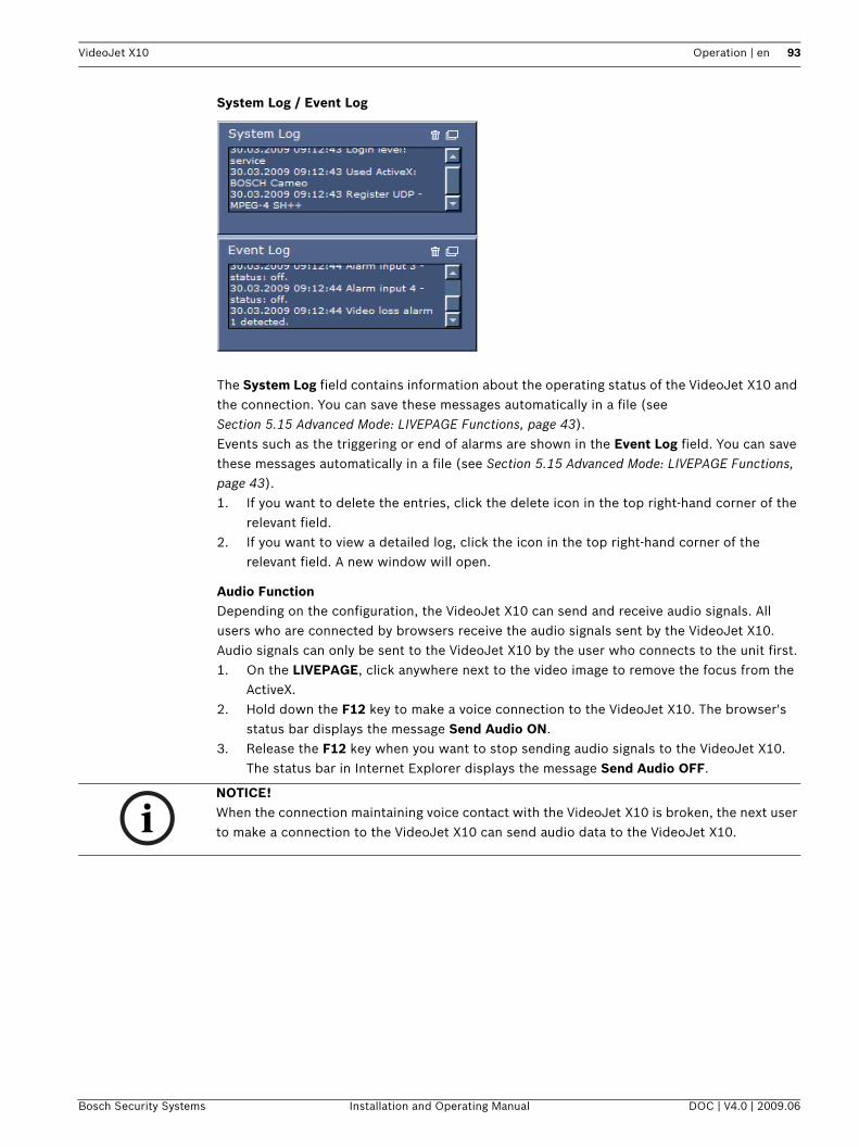
VideoJet X10 Operation | en 93
System Log / Event Log
The System Log field contains information about the operating status of the VideoJet X10 and the connection. You can save these messages automatically in a file (see Section 5.15 Advanced Mode: LIVEPAGE Functions, page 43).Events such as the triggering or end of alarms are shown in the Event Log field. You can save these messages automatically in a file (see Section 5.15 Advanced Mode: LIVEPAGE Functions, page 43).1. If you want to delete the entries, click the delete icon in the top right-hand corner of the
relevant field.2. If you want to view a detailed log, click the icon in the top right-hand corner of the
relevant field. A new window will open.
Audio FunctionDepending on the configuration, the VideoJet X10 can send and receive audio signals. All users who are connected by browsers receive the audio signals sent by the VideoJet X10.Audio signals can only be sent to the VideoJet X10 by the user who connects to the unit first.1. On the LIVEPAGE, click anywhere next to the video image to remove the focus from the
ActiveX.2. Hold down the F12 key to make a voice connection to the VideoJet X10. The browser's
status bar displays the message Send Audio ON.3. Release the F12 key when you want to stop sending audio signals to the VideoJet X10.
The status bar in Internet Explorer displays the message Send Audio OFF.
iNOTICE! When the connection maintaining voice contact with the VideoJet X10 is broken, the next user to make a connection to the VideoJet X10 can send audio data to the VideoJet X10.
Bosch Security Systems Installation and Operating Manual DOC | V4.0 | 2009.06

94 en | Operation VideoJet X10
6.3 Saving SnapshotsYou can save individual images from the video sequence currently shown on the LIVEPAGE in JPEG format on your computer's hard drive. The icon for recording single images is only visible if the unit is configured to enable this process (see Section Allow snapshots, page 44).
Click the icon. The image is saved at a resolution of 704 × 576 pixels (4CIF). The storage location depends on the configuration of the VideoJet X10 (see Section Path for JPEG and MPEG files, page 44).
6.4 Recording Video SequencesYou can save sections of the video sequence currently shown on the LIVEPAGE on your computer's hard drive. The icon for recording video sequences is only visible if the unit is configured to enable this process (see Section Allow local recording, page 44).1. Click the icon to start recording. The storage location depends on the configuration of
the VideoJet X10 (see Section Path for JPEG and MPEG files, page 44). A red dot in the icon indicates that recording is in progress.
2. Click the icon again to stop recording.
Image ResolutionSequences are saved at the resolution that has been preset in the configuration for the encoder (see Section 5.19 Advanced Mode: Encoder Profile, page 47).
6.5 Running Recording ProgramThe hard drive icon below the camera images on the LIVEPAGE changes during an automatic recording.
A moving graphic will appear to indicate a running recording. If no recording is taking place, a static icon is displayed.
iNOTICE! You can play back saved video sequences using the Player from Bosch Security Systems, which can be installed from the product CD supplied (see Section 3.1 Scope of Delivery, page 11).
DOC | V4.0 | 2009.06 Installation and Operating Manual Bosch Security Systems

VideoJet X10 Operation | en 95
6.6 The RECORDINGS PageThe RECORDINGS page for playing back recorded video sequences can be accessed from the LIVEPAGE and from the SETTINGS menu.The RECORDINGS link is only visible if a storage medium has been selected (see Section 5.21 Advanced Mode: Storage Management, page 51).
Click the RECORDINGS link in the navigation bar in the upper section of the window. The playback page appears.
CameraHere you can select the camera from which you want to view the recordings. Playback of the recordings starts immediately in the video window.
RecordingHere you can select the recording that you want to view. Playback of the recording starts immediately in the video window.
Controlling a Playback
You will see a time bar below the video image for quick orientation. A green arrow above the bar indicates the position of the image currently being played back within the sequence.
Bosch Security Systems Installation and Operating Manual DOC | V4.0 | 2009.06

96 en | Operation VideoJet X10
The time bar offers various options for navigation.Red bars indicate the points in time where alarms were triggered. Drag the green arrow to navigate to these points quickly.1. You can change the time interval by clicking the zoom keys (magnifying glass icons). The
display can span a range from two months to a few seconds.2. Drag the green arrow to the point in time at which playback should begin. The date and
time display below the bar provides orientation to the second.
ButtonsYou can control playback by means of the buttons below the video image. The buttons have the following functions:
Slide ControlYou can use the slide control to control playback speed.
BookmarksIn addition, you can set markers in the sequences, so-called bookmarks, and jump directly to these. These bookmarks are indicated as small yellow arrows above the time interval. Use the bookmarks as follows:
Right-click a bookmark to delete it.
Trick ModeIf you are using a mouse with a scroll wheel, you can view recordings frame by frame in trick mode. To do this, place the mouse cursor in the timeline below the timescale and turn the scroll wheel. Playback is automatically stopped (paused) during scrolling. Trick mode requires
Start or pause playback
Jump to the start of the active video sequence or to the previous sequence
Jump to the start of the next video sequence
Jump to the previous bookmark
Set bookmark
Jump to the following bookmark
iNOTICE! Bookmarks are only valid while you are in the RECORDINGS page; they are not saved with the sequences. As soon as you leave the page all bookmarks are deleted.
DOC | V4.0 | 2009.06 Installation and Operating Manual Bosch Security Systems

VideoJet X10 Operation | en 97
significantly higher memory capacity and computing power. For this reason, the number of cameras used in this mode can be restricted in the Configuration Manager program.
6.7 Installing the PlayerYou can play back saved video sequences using the Player from Bosch Security Systems, which can be installed from the product CD supplied (see Section 3.1 Scope of Delivery, page 11).
1. Insert the CD into the computer's CD-ROM drive. If the CD does not start automatically, open the CD in Windows Explorer and double-click the index.html file to start the menu.
2. From the list field at the top, select the language you require and click Tools in the menu.3. Click the Archive Player option. The installation will start. Follow the instructions in the
installation program. The Archive Player will be installed at the same time as the Player.4. After successful installation, you will find two new icons on your desktop for the Player
and the Archive Player.5. Start the Player by double-clicking the Player icon.
iNOTICE! In order to play back saved sequences using the Player, suitable MPEG ActiveX software must be installed on the computer.
Bosch Security Systems Installation and Operating Manual DOC | V4.0 | 2009.06
98 en | Operation VideoJet X10
6.8 Hardware Connections Between Video ServersA VideoJet X10 with a camera connected to it can be used as a sender and a compatible MPEG-4 hardware decoder (such as the VIP XD) with a connected monitor as a receiver using an Ethernet network connection. In this way it is possible to cover long distances without the need for major installation or cabling work.
InstallationCompatible video servers are designed to connect to one another automatically, provided they are correctly configured. They only need to be part of a closed network. Proceed as follows to install the units:1. Connect the units to the closed network using Ethernet cables.2. Connect them to the power supply.
ConnectingThere are three options for establishing a connection between a sender and a compatible receiver in a closed network:– an alarm,– a terminal program, or– Internet Explorer.
Connecting on AlarmWith the appropriate configuration, a connection between a sender and a receiver is made automatically when an alarm is triggered (see Section 5.27 Advanced Mode: Alarm Connections, page 59). After a short time the live video image from the sender appears on the connected monitor.This option can also be used to connect a sender and a compatible receiver using a switch connected to the alarm input. You do not need a computer to make the connection in this case.
iNOTICE! The sender and receiver must be located in the same subnet to establish a hardware connection.
iNOTICE! Make sure that the units are configured for the network environment and that the correct IP address for the remote location to be contacted in the event of an alarm is set on the Alarm Connections configuration page (see Section 5.27 Advanced Mode: Alarm Connections, page 59).
iNOTICE! Connecting with a Web browser is described in the manual of the relevant unit that is to be used as the receiver, for example VIP XD.
DOC | V4.0 | 2009.06 Installation and Operating Manual Bosch Security Systems

VideoJet X10 Operation | en 99
Connecting with a Terminal ProgramVarious requirements must be met in order to operate with a terminal program (see Section 8.9 Communication with Terminal Program, page 110).1. Start the terminal program and enter the command 1 in the main menu to switch to the
IP menu.2. Enter the command 4 in the IP menu to change the remote IP address, then enter the IP
address of the unit you wish to connect to.3. Enter the command 0 to return to the main menu and then enter the command 4 to
switch to the Rcp+ menu.4. In the Rcp+ menu, enter the command 5 to activate the automatic connection.
Closing the Connection with a Terminal Program1. Start the terminal program and enter the command 4 in the main menu to switch to the
Rcp+ menu.2. In the Rcp+ menu, enter the command 5 to deactivate the automatic connection.
Bosch Security Systems Installation and Operating Manual DOC | V4.0 | 2009.06

100 en | Operation VideoJet X10
6.9 Operation Using Software DecodersThe VideoJet X10 video server combines with VIDOS to provide a high-performance system solution.VIDOS is a software package for operating, controlling and managing CCTV installations (such as surveillance systems) at remote locations. It runs under Microsoft Windows operating systems. It is primarily designed for decoding video, audio and control data received from a remote sender.Many options are provided for operation and configuration when using a VideoJet X10 with VIDOS. Please refer to the software documentation for more details.
Another program that supports the VideoJet X10 is Bosch Video Management System.Bosch Video Management System is an IP video security solution that enables the seamless management of digital video, audio and data over any IP network. It was developed for use with Bosch CCTV products as one component of an extensive video security management system. It allows you to integrate your existing components into a simple-to-control system or into the entire Bosch range, benefiting from a complete security solution based on the latest technology and years of experience.
The VideoJet X10 video server is also designed for use with the DiBos 8 digital recorder.DiBos 8 records up to 32 video and audio streams and is available as IP software or hybrid DVR with additional analog camera and audio inputs. DiBos supports the most diverse functions on the VideoJet X10 video server, for example relay activation, remote control of peripherals and remote configuration. DiBos 8 can use the alarm inputs for event triggering and, on release of the MOTION+ motion detector, record the activated cells to enable intelligent motion search.
DOC | V4.0 | 2009.06 Installation and Operating Manual Bosch Security Systems

VideoJet X10 Maintenance and Upgrades | en 101
7 Maintenance and Upgrades
7.1 Testing the Network Connection You can use the ping command to check the connection between two IP addresses. This allows you to test whether a unit in the network is active.1. Open the DOS command prompt.2. Type ping followed by the IP address of the unit.If the unit is found, the response appears as Reply from ... followed by the number of bytes sent and the transmission time in milliseconds. If not, the unit cannot be accessed over the network. This might be because:– The unit is not correctly connected to the network. Check the cable connections in this
case.– The unit is not correctly integrated into the network. Check the IP address, subnet mask
and gateway address.
7.2 Unit ResetYou can use the Factory Reset button to restore the unit to its original settings. Any changes to the settings are overwritten by the factory defaults. A reset may be necessary, for example, if the unit has invalid settings that prevent it from functioning as desired.
1. If necessary, back up the current configuration using the Download button on the Maintenance configuration page (see Section 5.43 Advanced Mode: Maintenance, page 84).
2. Using a pointed object, press the Factory Reset button located below the orange terminal block until the Connect LED flashes red (see Section 3.4 Connections on the Front Panel, page 16). All settings will revert to their defaults.
3. Change the IP address of the VideoJet X10 if necessary.4. Configure the unit to meet your requirements.
!CAUTION! All configured settings will be discarded during a reset.If necessary, back up the current configuration using the Download button on the Maintenance configuration page (see Section 5.43 Advanced Mode: Maintenance, page 84).
iNOTICE! After a reset, the unit can only be addressed via the factory default IP address. The IP address can be changed as described in the Installation chapter (see Section 4.5 Setup Using the Configuration Manager, page 25).
Bosch Security Systems Installation and Operating Manual DOC | V4.0 | 2009.06
102 en | Maintenance and Upgrades VideoJet X10
7.3 Repairs
Ensure that all maintenance or repair work is carried out only by qualified personnel (electrical engineers or network technology specialists). In case of doubt, contact your dealer's technical service center.
7.4 Transfer and DisposalThe VideoJet X10 should only be passed on together with this installation and operating manual.Your Bosch product is designed and manufactured with high-quality materials and components which can be recycled and reused.
This symbol means that electrical and electronic equipment, at their end-of-life, should be disposed of separately from your household waste.In the European Union, there are separate collection systems for used electrical and electronic products. Please dispose of this equipment at your local community waste collection/recycling center.
!CAUTION! Never open the housing of the VideoJet X10.The unit does not contain any user-serviceable parts.
DOC | V4.0 | 2009.06 Installation and Operating Manual Bosch Security Systems
VideoJet X10 Appendix | en 103
8 Appendix
8.1 TroubleshootingIf you are unable to resolve a malfunction, please contact your supplier or systems integrator, or go directly to Bosch Security Systems Customer Service.You can view a range of information about your unit version on the System Overview page (see Section 5.45 Advanced Mode: System Overview, page 86). Make a note of this information before contacting Customer Service. You can download an internal maintenance log from the unit on the Maintenance page if you wish to send it to Customer Service by e-mail (see Section Maintenance log, page 85).
The following tables are intended to help you identify the causes of malfunctions and correct them where possible.
Bosch Security Systems Installation and Operating Manual DOC | V4.0 | 2009.06

104 en | Appendix VideoJet X10
8.2 General Malfunctions
Malfunction Possible causes Recommended solution
No connection between the unit and terminal program.
Incorrect cable connections. Check all cables, plugs, contacts, terminals and connections.
The computer's serial interface is not connected.
Check the other serial interface.
Interface parameters do not match.
If necessary select a different interface and make sure that the computer's interface parameters match those of the unit. Try the following standard parameters: 19,200 baud, 8 data bits, no parity, 1 stop bit. Next, disconnect the unit from the power supply and reconnect it again after a few seconds.
No image transmission to remote station.
Camera error. Connect local monitor to the camera and check the camera function.
Faulty cable connections. Check all cables, plugs, contacts and connections.
No connection established, no image transmission.
The unit's configuration. Check all configuration parameters.
Faulty installation. Check all cables, plugs, contacts and connections.
Wrong IP address. Check the IP addresses (terminal program).
Faulty data transmission within the LAN.
Check the data transmission with ping.
The maximum number of connections has been reached.
Wait until there is a free connection and then call the sender again.
No audio transmission to remote station.
Hardware fault. Check that all connected audio units are operating correctly.
Faulty cable connections. Check all cables, plugs, contacts and connections.
Incorrect configuration. Check audio parameters on the Audio configuration and LIVEPAGE Functions pages.
The audio voice connection is already in use by another receiver.
Wait until the connection is free and then call the sender again.
DOC | V4.0 | 2009.06 Installation and Operating Manual Bosch Security Systems
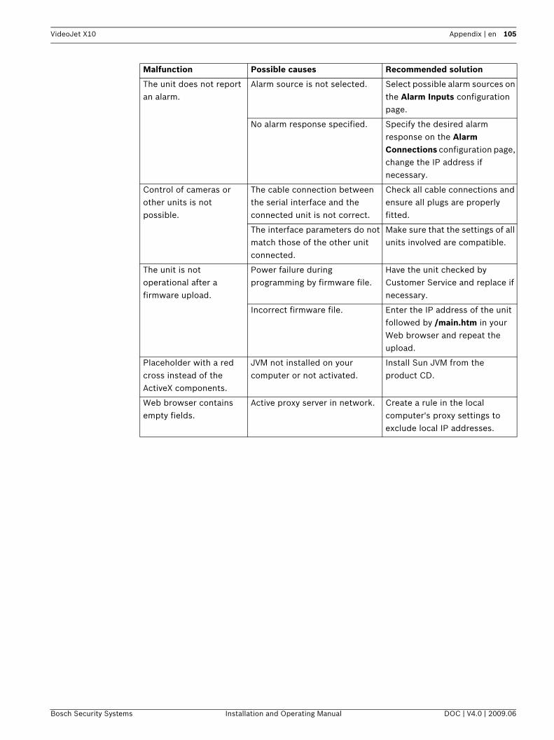
VideoJet X10 Appendix | en 105
The unit does not report an alarm.
Alarm source is not selected. Select possible alarm sources on the Alarm Inputs configuration page.
No alarm response specified. Specify the desired alarm response on the Alarm Connections configuration page, change the IP address if necessary.
Control of cameras or other units is not possible.
The cable connection between the serial interface and the connected unit is not correct.
Check all cable connections and ensure all plugs are properly fitted.
The interface parameters do not match those of the other unit connected.
Make sure that the settings of all units involved are compatible.
The unit is not operational after a firmware upload.
Power failure during programming by firmware file.
Have the unit checked by Customer Service and replace if necessary.
Incorrect firmware file. Enter the IP address of the unit followed by /main.htm in your Web browser and repeat the upload.
Placeholder with a red cross instead of the ActiveX components.
JVM not installed on your computer or not activated.
Install Sun JVM from the product CD.
Web browser contains empty fields.
Active proxy server in network. Create a rule in the local computer's proxy settings to exclude local IP addresses.
Malfunction Possible causes Recommended solution
Bosch Security Systems Installation and Operating Manual DOC | V4.0 | 2009.06

106 en | Appendix VideoJet X10
8.3 Malfunctions with iSCSI Connections
Malfunction Possible causes Recommended solution
After connecting to the iSCSI destination, no LUNs are displayed.
Incorrect LUN mapping during iSCSI system configuration.
Check the iSCSI system configuration and reconnect.
After connecting to the iSCSI destination, "LUN FAIL" appears below a node.
The LUN list could not be read, as it was assigned to the wrong network interface.
Check the iSCSI system configuration and reconnect.
LUN mapping is not possible.
Some iSCSI systems do not support the use of an initiator extension.
Delete the initiator extension on the Identification configuration page.
DOC | V4.0 | 2009.06 Installation and Operating Manual Bosch Security Systems
VideoJet X10 Appendix | en 107
8.4 LEDsThe VideoJet X10 network video server has a number of LEDs on its front and rear panels that show the operating status and can give indications of possible malfunctions:
Power On LED
SFP LED
ETH 1 LED
ETH 2 LED
Connect LED
HDD LED
Does not light up: VideoJet X10 is switched off.
Lights up green: VideoJet X10 is switched on.
Does not light up: No connection.
Lights up yellow: Connection established.
Flashes yellow: Data being transmitted.
Does not light up: No network connection.
Lights up yellow: Network connection established.
Flashes yellow: Data being transmitted over the network.
Does not light up: No network connection.
Lights up yellow: Network connection established.
Flashes yellow: Data being transmitted over the network.
Lights up red: Startup in progress.
Lights up green: Startup complete, VideoJet X10 is operational.
Flashes green: Video connection established.
Flashes red: VideoJet X10 is faulty, for example following failed firmware upload.
Does not light up: No hard drive fitted.
Lights up orange: Hard drive fitted.
Flashes orange: Hard drive activity.
Bosch Security Systems Installation and Operating Manual DOC | V4.0 | 2009.06

108 en | Appendix VideoJet X10
8.5 Processor LoadIf the VideoJet X10 is accessed via the Web browser, you will see the processor load indicator in the top right of the window next to the manufacturer's logo.
You can obtain additional information to help you when troubleshooting or fine tuning the unit. The values indicate the proportions of the individual functions on the encoder load, shown as percentages. The JPEG parameter relates to snapshots and M-JPEG. The scaler converts the input format 4CIF to the other formats configured.1. Move the cursor over the graphic indicator. Some additional numerical values are also
displayed.2. Click the graphic indicator. Further details are displayed.
8.6 Network Connection
You can display information about the network connection. To do this, move the cursor over the i icon.
8.7 Serial InterfaceOptions for using the serial interface include transferring transparent data, controlling connected units or operating the unit with a terminal program. The serial interface supports the RS-232, RS-422 and RS-485 transmission standards. The mode used depends on the current configuration (see Section 5.37 Advanced Mode: COM1, page 76). Connection is via the terminal block.
Link Ethernet link type
UL Uplink, speed of the outgoing data traffic
DL Downlink, speed of the incoming data traffic
DOC | V4.0 | 2009.06 Installation and Operating Manual Bosch Security Systems

VideoJet X10 Appendix | en 109
8.8 Terminal BlockThe terminal block has several contacts for:– 4 alarm inputs– 4 relay outputs– Serial data transmission
Pin AssignmentThe pin assignment of the serial interface depends on the interface mode used (see Section 5.37 Advanced Mode: COM1, page 76).
Connect each alarm input to a ground contact (GND) when connecting alarm inputs.For the RM1 and RM2 contact specifications, see Section Remote Indication of the Connection Status, page 23.For the backup power supply specifications, see Section Backup Power Supply, page 24.
Contact RS-232 mode RS-422 mode RS-485 mode
CTS CTS (clear to send) RxD- (receive data minus) Data-
TXD TxD (transmit data) TxD- (transmit data minus)
RTS RTS (ready to send) TxD+ (transmit data plus) Data+
RXD RxD (receive data) RxD+ (receive data plus)
GND GND (ground) — —
Contact Function
IN1 Input alarm 1
IN2 Input alarm 2
IN3 Input alarm 3
IN4 Input alarm 4
GND Ground
R1 Relay output 1
R2 Relay output 2
R3 Relay output 3
R4 Relay output 4
RM1 LED remote indicator
RM2 LED remote indicator
BP Backup power supply
GND Ground
+ 10 to 30 V (power supply)
– Ground
Bosch Security Systems Installation and Operating Manual DOC | V4.0 | 2009.06
110 en | Appendix VideoJet X10
8.9 Communication with Terminal ProgramData TerminalIf a VideoJet X10 cannot be found in the network or the connection to the network is interrupted, you can connect a data terminal to the VideoJet X10 for initial setup and setting of important parameters. The data terminal consists of a computer with a terminal program.You require a serial transmission cable with a 9-pin Sub-D plug to connect to the computer and open ends for connection to the terminal block of the VideoJet X10 (see Section Pin Assignment, page 109).HyperTerminal, a communications accessory included with Microsoft Windows, can be used as the terminal program.
1. Disconnect the VideoJet X10 from the Ethernet network before working with the terminal program.
2. Connect the serial interface of the VideoJet X10 using any available serial interface on the computer.
Configuring the TerminalBefore the terminal program can communicate with the VideoJet X10, the transmission parameters must be matched. Make the following settings for the terminal program:– 19,200 bps– 8 data bits– No parity check– 1 stop bit– No protocol
Command InputsAfter the connection has been established, you must log on to the VideoJet X10 to access the main menu. Other submenus and functions can be accessed using the on-screen commands.1. If necessary, turn off the local echo so that entered values are not repeated on the
display.2. Enter one command at a time.3. When you have entered a value, such as the IP address, check the characters you have
entered before pressing Enter to transfer the values to the VideoJet X10.
iNOTICE! Information on installing and using HyperTerminal can be found in the manuals or in the online help for Microsoft Windows.
DOC | V4.0 | 2009.06 Installation and Operating Manual Bosch Security Systems

VideoJet X10 Appendix | en 111
Assigning an IP AddressBefore you can operate a VideoJet X10 in your network you must first assign it an IP address that is valid for your network.The following default address is preset at the factory: 192.168.0.11. Start a terminal program such as HyperTerminal.2. Enter the user name service. The terminal program displays the main menu.3. Enter command 1 to open the IP menu.
4. Enter 1 again. The terminal program displays the current IP address and prompts you to enter a new IP address.
5. Enter the desired IP address and press Enter. The terminal program displays the new IP address.
6. Use the displayed commands for any additional settings you require.
RebootBriefly interrupt the power supply to the VideoJet X10 for a reboot (disconnect the power supply unit from the mains supply and switch on again after a few seconds).
Additional ParametersYou can use the terminal program to check other basic parameters and modify them where necessary. Use the on-screen commands in the various submenus to do this.
iNOTICE! You must reboot to activate the new IP address, a new subnet mask or a gateway IP address.
Bosch Security Systems Installation and Operating Manual DOC | V4.0 | 2009.06

112 en | Appendix VideoJet X10
8.10 CopyrightsThe firmware 4.0 uses the fonts "Adobe-Helvetica-Bold-R-Normal--24-240-75-75-P-138-ISO10646-1" and "Adobe-Helvetica-Bold-R-Normal--12-120-75-75-P-70-ISO10646-1" under the following copyright:Copyright 1984-1989, 1994 Adobe Systems Incorporated.Copyright 1988, 1994 Digital Equipment Corporation.Permission to use, copy, modify, distribute and sell this software and its documentation for any purpose and without fee is hereby granted, provided that the above copyright notices appear in all copies and that both those copyright notices and this permission notice appear in supporting documentation, and that the names of Adobe Systems and Digital Equipment Corporation not be used in advertising or publicity pertaining to distribution of the software without specific, written prior permission.
This software is based in part on the work of the Independent JPEG Group.
DOC | V4.0 | 2009.06 Installation and Operating Manual Bosch Security Systems

VideoJet X10 Specifications | en 113
9 Specifications
9.1 Unit
Operating voltage 10 to 30 V DC, power supply via external unit
Power consumption Approx. 16 W with full equipment
LAN interfaces 2 × Ethernet 10/100 Base-T, automatic adjustment,half/full duplex, RJ45
Data interfaces 1 × RS-232/RS-422/RS-485, bidirectional, push-in terminal2 × USB 2.0, 2.5 W max. each
SFP slot 1 × 1 Gbps, for mini-GBIC modules
CF slot 1 × CompactFlash type I and II, for standard CF cards
Alarm inputs 4 × push-in terminals (non-isolated closing contact), maximum activation resistance 10 Ohm
Relay outputs 4 × push-in terminal, 30 Vp-p, 2 A (SELV), 8 contacts
Video input 1 × BNC socket 0.7 to 1.2 Vp-p, 75 Ohm, PAL/NTSC
Audio input 1 × 3.5 mm stereo socket 5.5 Vp-p max., impedance 9 kOhm typ.
Audio output 1 × 3.5 mm stereo socket, 3.0 Vp-p max. at impedance 10 kOhm typ.,
1.7 Vp-p max. at impedance 16 Ohm typ.
Displays 2 × LED (video link, hard drive) on front panel, 4 × LED (operating voltage, 2 × network connection, SFP connection) on the rear panel
Thermal value 55 BTU/h with full equipment
Operating conditions Temperature: –30 to +60 °C / –22 to +140 °Frelative humidity: 0 to 95%, non-condensingunits with a hard drive: elevation 0 to 3,000 m / 1.86 miles
Approvals IEC 60950; UL 60950; AS/NZS 3548 Class B; EN 50130-4; EN 50121-4; EN 55103-1; EN 55022; EN 55024; EN 60068-2-1 Ab; EN 60068-2-2 Bb; EN 60068-2-6 Fc; EN 60068-2-14 Na; EN 60068-2-30 Db; EN 61000-3-2; EN 61000-3-3; FCC 47 CFR Chapter 1 Part 15
Dimensions (H × W × D) 61 × 160 × 178 mm / 2.4 × 6.3 × 7.0 in, including BNC connections
Weight Approx. 1.5 kg / 3.3 lb, including HDD
Bosch Security Systems Installation and Operating Manual DOC | V4.0 | 2009.06
114 en | Specifications VideoJet X10
9.2 Protocols/Standards
Video standards PAL, NTSC
Video coding protocols H.264 Baseline Profile, MPEG-4, M-JPEG, JPEG
Video data rate 9.6 kbps to 6 Mbps
Image resolutions (PAL/NTSC) 704 × 576/480 pixels (4CIF/D1)704 × 288/240 pixels (2CIF)464 × 576/480 pixels (2/3 D1)352 × 576/480 pixels (1/2 D1)352 × 288/240 pixels (CIF)176 × 144/120 pixels (QCIF)
Total delay 120 ms (PAL/NTSC, MPEG-4, no network delay)
Image refresh rate 25/30 ips max.
Network protocols RTP, Telnet, UDP, TCP, IP, HTTP, HTTPS, DHCP, IGMP V2, IGMP V3, ICMP, RTSP, FTP, ARP, SNTP, SNMP (V1, MIB-II), 802.1x
Audio coding protocol G.711, 300 Hz to 3.4 kHz
Audio sampling rate 8 kHz
Audio data rate 80 kbps
DOC | V4.0 | 2009.06 Installation and Operating Manual Bosch Security Systems
VideoJet X10 Glossary | en 115
10 Glossary
Symbols
10/100/1000 Base-T IEEE-802.3 specification for 10, 100 or 1000 Mbps Ethernet
802.1x The IEEE 802.1x standard provides a general method for authentication and authorization in IEEE-802 networks. Authentication is carried out via the authenticator, which checks the transmitted authentication information using an authentication server (see RADIUS server) and approves or denies access to the offered services (LAN, VLAN or WLAN) accordingly.
A
ARP Address Resolution Protocol: a protocol for mapping MAC and IP addresses
B
Baud Unit of measurement for the speed of data transmission
bps Bits per second, the actual data rate
BVIP Bosch Video over IP unit
C
CF CompactFlash; interface standard, for digital storage media amongst other things. Used in computers in the form of CF cards, digital cameras and Personal Digital Assistants (PDA).
CIF Common Intermediate Format, video format with 352 × 288/240 pixels
D
DHCP Dynamic Host Configuration Protocol: uses an appropriate server to enable dynamic assignment of an IP address and other configuration parameters to computers on a network (Internet or LAN).
DNS Domain Name System, mainly used for converting domain names to IP addresses
DynDNS DNS hosting service that works according to RFC 2845 and stores the IP addresses of its clients in a database, ready for use
F
FTP File Transfer Protocol
Full duplex Simultaneous data transmission in both directions (sending and receiving)
G
GBIC GigaBit Interface Converter; applied in network technology to render interfaces flexible, for converting an electrical interface into an optical interface, for example. This enables flexible operation of an interface as a Gigabit Ethernet via twisted-pair cables or fiber optic cables.
GOP Group of Pictures
Bosch Security Systems Installation and Operating Manual DOC | V4.0 | 2009.06
116 en | Glossary VideoJet X10
H
HTTP Hypertext Transfer Protocol: protocol for transmitting data over a network
HTTPS Hypertext Transfer Protocol Secure: encrypts and authenticates communication between Web server and browser
I
ICMP Internet Control Message Protocol
ID Identification: a machine readable character string
IEEE Institute of Electrical and Electronics Engineers
IGMP Internet Group Management Protocol
Internet Protocol The main protocol used on the Internet, normally in conjunction with the Transfer Control Protocol (TCP): TCP/IP
IP See Internet Protocol
IP address A 4-byte number uniquely defining each unit on the Internet. It is usually written in dotted decimal notation, for example "209.130.2.193".
iSCSI Storage over IP process for storage networks; specifies how storage protocols are operated over IP
ISDN Integrated Services Digital Network
J
JPEG An encoding process for still images (Joint Photographic Experts Group)
K
kbps Kilobits per second, the actual data rate
L
LAN See Local Area Network
Local Area Network A communications network serving users within a limited geographical area such as a building or university campus. It is controlled by a network operating system and uses a transfer protocol.
LUN Logical Unit Number; logical drive in iSCSI storage systems
M
MAC Media Access Control
MIB Management Information Base; a collection of information for remote servicing using the SNMP protocol
MPEG-2 Improved video/audio compression standard, compression on highest level allows images in studio quality; now established as broadcast standard
DOC | V4.0 | 2009.06 Installation and Operating Manual Bosch Security Systems

VideoJet X10 Glossary | en 117
MPEG-4 A further development of MPEG-2 designed for transmitting audiovisual data at very low transfer rates (for example over the Internet)
MSS Maximum Segment Size; maximum byte figure for the user data in a data packet
N
Net mask A mask that explains which part of an IP address is the network address and which part is the host address. It is usually written in dotted decimal notation, for example "255.255.255.192".
NTP Network Time Protocol; a standard for synchronizing computer system clocks via packet-based communication networks. NTP uses the connectionless network protocol UDP. This was developed specifically for enabling time to be reliably transmitted over networks with variable packet runtime (Ping).
O
OF Optical Fiber; now used predominantly as the transmission medium for line-borne telecommunication processes (glass fiber cable)
P
Parameters Values used for configuration
Q
QCIF Quarter CIF, video format with 176 × 144/120 pixels
R
RADIUS server Remote Authentication Dial-In User Service: a client/server protocol for the authentication, authorization and accounting of users with dial-up connections on a computer network. RADIUS is the de-facto standard for central authentication of dial-up connections via Modem, ISDN, VPN, Wireless LAN (see 802.1x) and DSL.
RFC 868 A protocol for synchronizing computer clocks over the Internet
RS-232/-422/-485 Standards for serial data transmission
RTP Real-Time Transport Protocol; a transmission protocol for real-time video and audio
RTSP Real-Time Streaming Protocol; network protocol for controlling the continuous transmission of audiovisual data (streams) or software over IP-based networks
S
SFP Small Form-factor Pluggable; small, standardized module for network connections, designed as a plug connector for high-speed network connections
SNIA Storage Networking Industry Association; association of companies for defining the iSCSI standard
SNMP Simple Network Management Protocol; a protocol for network management, for managing and monitoring network components
Bosch Security Systems Installation and Operating Manual DOC | V4.0 | 2009.06

118 en | Glossary VideoJet X10
SNTP Simple Network Time Protocol; a simplified version of NTP (see NTP)
SSL Secure Sockets Layer; an encryption protocol for data transmission in IP-based networks
Subnet mask See Net mask
T
TCP Transmission Control Protocol
Telnet Login protocol with which users can access a remote computer (Host) on the Internet
TLS Transport Layer Security; TLS 1.0 and 1.1 are the standard advanced developments of SSL 3.0 (see SSL)
TTL Time-To-Live; life cycle of a data packet in station transfers
U
UDP User Datagram Protocol
URL Uniform Resource Locator
UTP Unshielded Twisted Pair
W
WAN See Wide Area Network
Wide Area Network A long distance link used to extend or connect remotely located local area networks
DOC | V4.0 | 2009.06 Installation and Operating Manual Bosch Security Systems

VideoJet X10 Index | en 119
11 IndexAActivating the recording 58Activation key 86Alarm 17, 41, 92Alarm e-mail 71Alarm input 22Alarm inputs 74Alarm message 41Alarm script 69Alarm sensors 55Audio connections 16, 20Audio input 16Audio output 16Audio settings 35, 50Audio stream on alarm 61Audio transmission 35, 43, 51Auto-connect 61BBasic mode 29Baud rate 76Bookmarks 96Browser window 91CCamera 76Camera name 31, 37Camera selection 91Cameras 20Car battery 24CF card 17, 21Changes 30Changes in light level 64Checking network 101Closing contact 22COM1 76CompactFlash 17, 21Configuration 27, 85Configuration download 85Configuration mode 29Connect on alarm 59Connecting 27, 98Contrast 46Control 76Control functions 92Control signals 43Controlling a playback 95Conventions 7DDanger 9Data bits 76Data interface 22Data terminal 110Date 39Date format 39Daylight saving time 39Default 49, 55, 62, 63Default profile 49Deleting recordings 53Device ID 37Device name 31, 37
DHCP server 33Display stamping 40Dome camera 22Dual Streaming 13, 47DynDNS 79EEcho 110Electromagnetic compatibility 8E-mail 71Encoder load 108Encoding 13Encryption protocol 78EPROM 84Establishing the connection 28, 90Event log 44, 93FFalse alarms 64Firewall 60, 78Firmware upload 84Formatting 53Front panel connections 16FTP server 83Function test 87GGateway 33, 78GBIC module 17General password 60HHolidays 58, 68HTTP port 78HTTPS port 78IIdentification 8, 31, 37IEEE 802.1x 81IGMP 82Image quality 82Image resolution 94Image selection 91Initiator name 38Installation 9Installation conditions 19Installation location 19Interface 108Interface mode 76Internal clock 39IP address 33, 78, 111iSCSI settings 52JJPEG image size 83JPEG posting 83JPEG posting interval 83LLanguage 42Licenses 86Live video images 27, 89Livepage 43Low Voltage Directive 8Low-pass filter 46
Bosch Security Systems Installation and Operating Manual DOC | V4.0 | 2009.06

120 en | Index VideoJet X10
MMain functions 15Maintenance 9Manufacturer logo 41Media-replay 95Milliseconds 41Motion detector 62Motion detector defaults 62, 63Motion detector object size 65Motion detector sensitivity 65MPEG ActiveX 27, 89, 97MTU value 78, 79Multicast address 82Multicast connection 78, 82Multicast function 13Multicasting 81Multi-unicast 81NNavigation 30Network 20, 33, 77, 80Network connection 17, 25, 108Number of connections 28, 91OOF 21Operation 9, 89Overview of functions 13PParameters 26, 111Parity check 76Password 29, 31, 32, 38, 91Peripheral device control 92Picture settings 46Pin assignment 109Playback 95Playback button 96Player 97Port 78, 82Post-alarm profile 55Post-alarm time 55Power off 25Power on 25Power supply 9, 17, 25Power switch 25Pre-alarm time 55Processor load 108Processor load indicator 108Product name 41Profile configuration 48Profiles 34, 47Protocol 76RRADIUS 81Rear panel connections 17Reboot 26, 111Receiver 13Receiver password 60Recording media 52Recording profiles 54Recording program 94Recording scheduler 57
Recording status 58Recording video sequences 94Reflections of light 64Regulations 7Relay 17, 23Relay output 74Relay outputs 23Remote control 14Remote indication 23Remote LED 23Repair 9, 102Reset 17, 101Router 82SSafety 9Saturation 46Saving event log 44Saving system log 44Scaler 108Scope of delivery 11Screen resolution 12, 27, 89Select Area 66Select area 65, 66Selecting a profile 47Sensor fields 65, 66Serial interface 17Serial number 8Serial port function 76SFP 17, 21Signal source 22SMS 72Snapshots 14, 94SNMP 80SNTP server 33, 40Software decoder 100Source type 45SSL certificate 85SSL encryption 61Standard recording profile values 55Stop bits 76Storage media 52Storage medium 36, 51Streaming 82Subnet mask 33, 78Summer time 39Symbols 7Synchronize 32, 39System log 44, 45, 93System requirements 12, 27, 89TTamper detection 65Target data rate 49TCP 60, 78Terminal 76Termination 45Test 87Time 24, 32, 39, 40Time server 32, 40Time server IP address 33, 40Time server protocol 32, 40Time signal 32, 40
DOC | V4.0 | 2009.06 Installation and Operating Manual Bosch Security Systems
VideoJet X10 Index | en 121
Time zone 39TLS 78Transmission parameters 110Transmission protocol 60, 78Transmission rate 76Transmission standards 22, 108Transparent 76Traps 81Trick mode 96Trigger 22Trigger relay 75TTL 82UUDP 60, 78Unicast 81Unit date 39Unit identification 31, 37Unit name 31, 37Unit reset 101Unit time 32, 39URL 28, 90USB interface 16User name 31, 38VValue 46VCR 45Video content analysis 62Video input 45Video sensor 62VRM 52WWatermarking 41
Bosch Security Systems Installation and Operating Manual DOC | V4.0 | 2009.06
122 en | Index VideoJet X10
DOC | V4.0 | 2009.06 Installation and Operating Manual Bosch Security Systems


Bosch Sicherheitssysteme GmbH Robert-Koch-Straße 10085521 OttobrunnGermanyTelefon 089 6290-0Fax 089 6290-1020www.boschsecurity.com© Bosch Sicherheitssysteme GmbH, 2009