viega megapress cuni system · rina registro italiano navale note: all systems must be installed...
TRANSCRIPT

The g loba l leader in p lumbing, heat ing
and p ipe jo in ing systems
Viega MegaPress CuNi SystemInstallation Manual

IM-MP 593258 0319 MegaPress CuNi 2
Heritage of quality, vision for the futureViega’s heritage of superiority demands nothing but the best for our customers. Engineered to be efficient, Viega products perform at the highest possible level, providing confidence and peace of mind. Viega is the only manufacturer to offer press systems in multiple pipe joining materials. More than one million Viega press fittings are installed every day around the world and, with a Supply Chain that can process orders in 48 hours or less, Viega is positioned to provide customers with the best, most versatile support in the industry.
Introducing the Viega MegaPress CuNi systemThe same press technology that revolutionized copper and stainless steel joining is also available for copper-nickel systems. Viega MegaPress CuNi is a copper-nickel, cold press system designed specifically to stand up to the harsh conditions found in marine environments. With its 90/10 copper-nickel alloy and FKM sealing element, Viega MegaPress CuNi is approved for a variety of different applications found onboard a ship, including fresh water, seawater and fuel oil systems. Viega combines reliability and speed to complete a pipe joining project quickly and efficiently, reducing re-work and costly downtime.
Do more with ViegaViega press technology is consistent and reliable, providing the same quality pipe connections every time. Viega press systems make secure connections in a matter of seconds, which helps keep a project on time or ahead of schedule. The Viega MegaPress system helps installers accomplish more in the same amount of time.
A true innovator since 1899, Viega is at the forefront of pipe joining technology. With personalized support, efficient delivery processes and trustworthy quality, no other manufacturer can provide the same level of service. The global leader in plumbing, heating and pipe joining systems, Viega is the name you can trust.
IMPORTANT NOTE:A WHITE DOT ON A VIEGA MEGAPRESS FITTING INDICATES THE SMART CONNECT TECHNOLOGY WITH AN FKM SEALING ELEMENT. FOR A CURRENT LIST OF APPLICATIONS, PLEASE VISIT WWW.VIEGA.US/APPLICATIONS
Viega products are designed to be installed by licensed and trained plumbing and mechanical professionals who are familiar with Viega products and their installation. Installation by non-professionals may void Viega LLC’s warranty.

3IM-MP 593258 0319 MegaPress CuNi
Contents
1 System Description1.1 Viega MegaPress CuNi . . . . . . . . . . . . . . . . . . . . . . . . . . . . . . . . . . . . . . . . . . . . . . . . . . . . . . . . . . 4
1.1.1 Shipbuilding codes . . . . . . . . . . . . . . . . . . . . . . . . . . . . . . . . . . . . . . . . . . . . . . . . . . . . . . . . 41.1.2 Shipbuilding type approvals: . . . . . . . . . . . . . . . . . . . . . . . . . . . . . . . . . . . . . . . . . . . . . . . . 4
1.3 Fitting description . . . . . . . . . . . . . . . . . . . . . . . . . . . . . . . . . . . . . . . . . . . . . . . . . . . . . . . . . . . . . . 51.3.1 Viega Smart Connect technology . . . . . . . . . . . . . . . . . . . . . . . . . . . . . . . . . . . . . . . . . . . . . 51.3.2 Sealing elements . . . . . . . . . . . . . . . . . . . . . . . . . . . . . . . . . . . . . . . . . . . . . . . . . . . . . . . . . 61.3.3 Fitting markings . . . . . . . . . . . . . . . . . . . . . . . . . . . . . . . . . . . . . . . . . . . . . . . . . . . . . . . . . . 6
2 Tools2.1 Tools . . . . . . . . . . . . . . . . . . . . . . . . . . . . . . . . . . . . . . . . . . . . . . . . . . . . . . . . . . . . . . . . . . . . . . . . 72.2 Pressing tools . . . . . . . . . . . . . . . . . . . . . . . . . . . . . . . . . . . . . . . . . . . . . . . . . . . . . . . . . . . . . . . . . 7
3 General Installation Instructions3.1 Pipe selection . . . . . . . . . . . . . . . . . . . . . . . . . . . . . . . . . . . . . . . . . . . . . . . . . . . . . . . . . . . . . . . . . 83.2 Handling instructions . . . . . . . . . . . . . . . . . . . . . . . . . . . . . . . . . . . . . . . . . . . . . . . . . . . . . . . . . . . . 83.3 Pipe preparation . . . . . . . . . . . . . . . . . . . . . . . . . . . . . . . . . . . . . . . . . . . . . . . . . . . . . . . . . . . . . . . 8
3.3.1 No-stop couplings . . . . . . . . . . . . . . . . . . . . . . . . . . . . . . . . . . . . . . . . . . . . . . . . . . . . . . . . 83.4 Pressing requirements . . . . . . . . . . . . . . . . . . . . . . . . . . . . . . . . . . . . . . . . . . . . . . . . . . . . . . . . . . . 9
3.4.1 Minimum distance between fittings . . . . . . . . . . . . . . . . . . . . . . . . . . . . . . . . . . . . . . . . . . . 93.4.2 Pressing in tight quarters . . . . . . . . . . . . . . . . . . . . . . . . . . . . . . . . . . . . . . . . . . . . . . . . . . . 93.4.3 Minimum space requirements for the press fitting process in front of and behind
components . . . . . . . . . . . . . . . . . . . . . . . . . . . . . . . . . . . . . . . . . . . . . . . . . . . . . . . . . . . 103.4.4 Pressing with ring and actuator in tight quarters . . . . . . . . . . . . . . . . . . . . . . . . . . . . . . . . 10
3.5 Welding requirements . . . . . . . . . . . . . . . . . . . . . . . . . . . . . . . . . . . . . . . . . . . . . . . . . . . . . . . . . . 113.5.1 Welding adjacent to Viega MegaPress CuNi fittings . . . . . . . . . . . . . . . . . . . . . . . . . . . . . . . . . .113.5.2 Welding in line with Viega MegaPress CuNi fittings . . . . . . . . . . . . . . . . . . . . . . . . . . . . . . . . . . . . . .11
3.6 General installation requirements . . . . . . . . . . . . . . . . . . . . . . . . . . . . . . . . . . . . . . . . . . . . . . . . . 113.6.1 Expansion . . . . . . . . . . . . . . . . . . . . . . . . . . . . . . . . . . . . . . . . . . . . . . . . . . . . . . . . . . . . . . 113.6.2 Electrical bonding . . . . . . . . . . . . . . . . . . . . . . . . . . . . . . . . . . . . . . . . . . . . . . . . . . . . . . . . 123.6.3 Piping exposed to freezing temperatures . . . . . . . . . . . . . . . . . . . . . . . . . . . . . . . . . . . . . . 123.6.4 Corrosion protection . . . . . . . . . . . . . . . . . . . . . . . . . . . . . . . . . . . . . . . . . . . . . . . . . . . . . . 123.6.5 Underground installations . . . . . . . . . . . . . . . . . . . . . . . . . . . . . . . . . . . . . . . . . . . . . . . . . 123.6.6 Pressure testing . . . . . . . . . . . . . . . . . . . . . . . . . . . . . . . . . . . . . . . . . . . . . . . . . . . . . . . . . 123.6.7 Threaded connections . . . . . . . . . . . . . . . . . . . . . . . . . . . . . . . . . . . . . . . . . . . . . . . . . . . . 123.6.8 Flange connections . . . . . . . . . . . . . . . . . . . . . . . . . . . . . . . . . . . . . . . . . . . . . . . . . . . . . . 123.6.9 Pipe hangers . . . . . . . . . . . . . . . . . . . . . . . . . . . . . . . . . . . . . . . . . . . . . . . . . . . . . . . . . . . . 12
3.7 Deflection . . . . . . . . . . . . . . . . . . . . . . . . . . . . . . . . . . . . . . . . . . . . . . . . . . . . . . . . . . . . . . . . . . . . . . . .133.7.1 Controlling deflection . . . . . . . . . . . . . . . . . . . . . . . . . . . . . . . . . . . . . . . . . . . . . . . . . . . . . 13
3.9 Viega MegaPress CuNi Pipe Marking Guide . . . . . . . . . . . . . . . . . . . . . . . . . . . . . . . . . . . . . . . . . 143.8 Identification . . . . . . . . . . . . . . . . . . . . . . . . . . . . . . . . . . . . . . . . . . . . . . . . . . . . . . . . . . . . . . . . . 143.10 Viega MegaPress CuNi fitting system ½" to 2" installation . . . . . . . . . . . . . . . . . . . . . . . . . . . . . 153.11 Viega MegaPress CuNi XL fitting system 2½" to 4" installation . . . . . . . . . . . . . . . . . . . . . . . . . 16
4 Warranty . . . . . . . . . . . . . . . . . . . . . . . . . . . . . . . . . . . . . . . . . . . . . . . . . . . . . . . . . . . . . . . . . .19

IM-MP 593258 0319 MegaPress CuNi 4
1 System Description
The Viega MegaPress CuNi fitting system is a state-of-the-art IPS press fitting system that provides an economical and reliable installation of class 200 and schedule 40 copper-nickel pipe. Viega MegaPress CuNi fittings are available in sizes ranging from ½" to 4" and provide a fast, reliable, consistent joining method.
Our products are the result of decades of experience in manufacturing press fittings. The Viega MegaPress CuNi fitting system is offered in configurations that allow for the installation of the vast majority of copper-nickel piping applications in the shipbuilding market.
The Viega MegaPress CuNi fitting system requires no threading or welding and poses no fire hazard, which is particularly important in restoration or retrofit work. The press fittings are installed with a battery-powered or corded pressing tool.
The advantages of installing Viega MegaPress CuNi fitting system include:
• Up to 90% time savings• Lowest overall installed cost• Proven joining technology• Technical field support• No fire watch needed• No special certification required
1.1 Viega MegaPress CuNiViega MegaPress CuNi ½" to 4" fittings feature an FKM sealing element suitable for the following applications:
Fresh Water• Machinery cooling• Fire main and water spray• Sprinkler system• Hot/Cold potable water
Seawater• Bilge and ballast• Wet or dry fire main• Foam system• Water spray• Sprinkler system• Cooling water systems
Flammable Fluids• Cargo oil• Fuel oil• Lube oil• Hydraulic oil
Miscellaneous• Compressed air system• Condensate return• Vacuum piping• Sewage discharge
Technical Data:*Operating Temperature: 23 to 284°F (-5 to 140°C)Operating Pressures: ½" to 3" - 232 psi max 4" - 181 psi maxSealing Element: FKMAlloy: 90/10 Copper-nickelStandard: ASTM F1387*Refer to your applicable type approval for exact parameters.
1.1.1 Shipbuilding codesMegaPress CuNi system conforms to the following:
• International Association of Classification Societies - Requirements concerning pipes and pressure vessels
• United Coast Guard, U.S. Department of Homeland Security
1.1.2 Shipbuilding type approvals:ABS American Bureau of ShippingLR Lloyd’s RegisterGL Germanischer LloydBV Bureau VeritasDNV Det Norske VeritagNK Nippon Kaiji KyokaiRINA Registro Italiano Navale
Note: All systems must be installed per local code requirements.

5IM-MP 593258 0319 MegaPress CuNi
1.3 Fitting descriptionViega MegaPress fittings contain a bite ring and separator ring as shown in Figure 1.1. The bite ring is a 420 stainless steel ring with bidirectional teeth that bite into the pipe and ensure that the fitting is locked securely to the piping.
The separator ring ensures that the sealing element and bite ring perform at maximum capacity by providing a positive physical separation. The separator ring is made from 304 stainless steel in ½" to 2" fittings and XL sizes fittings utilize a PBT separator ring.
Press jaws and actuator rings are available for various dimensions. Their constant compression produces a positive, nondetachable, mechanical joint.
1 Identify an unpressed connection during pressure testing when water flows past the sealing element.
2 Upon identification, use the Viega MegaPress tool to press the fitting, making a reliable leak-proof connection.
3 Viega MegaPress connections are fast, flameless and reliable.
Figure 1.2 Smart Connect technology
Sealing Element Stainless Steel
Grip Ring
Separator Ring
Figure 1.1
1.3.1 Viega Smart Connect technologyViega MegaPress CuNi systems, sizes ½" through 4", incorporate the Viega Smart Connect technology. Smart Connect is a patented technology, third-party tested, proven to identify unpressed connections during a step test.
Smart Connect allows liquid or gaseous testing media to bypass the sealing element of an unpressed connection. This provides a quick and easy method to identify unpressed connections before system commissioning.
To utilize the Smart Connect technology prior to commissioning, pressurize the system with 15-85 psi water or air and observe the pressure gauge. If the system will hold 15-85 psi, you may then continue to pressurize the system to local code or specified requirements or standards, up to 600 psi. If the system will not hold 15-85 psi there is either an opening in the system or a connection has been left unpressed. Utilize standard detection procedures to locate the unpressed connection. Once found, you may press the connection during the test after ensuring full insertion depth of the piping into the fitting. Testing the system for unpressed connections using the Viega Smart Connect technology is in no way meant as a replacement for testing to local code or specified requirements or standards for the installed system.
Unpressed connections in press systems without the Viega Smart Connect technology may not leak initially; however, they may unseat during future system operation. The Viega Smart Connect technology is designed to prevent this potential risk.

IM-MP 593258 0319 MegaPress CuNi 6
1.3.3 Fitting markingsMarkings on Viega MegaPress CuNi fittings include:
• White Dot: FKM sealing element and Smart Connect technology
• Size of fitting• Manufacturer name• Manufacturer date code• Country of origin• Batch code
1.3.2 Sealing elements
Viega MegaPress CuNi FKM Sealing ElementOperating temperature: 23°F to 284°F (-5°C to 140°C)
FKM is well known for its excellent resistance to petroleum products and solvents as well as exceptional high-temperature performance. The FKM sealing element is a special-purpose elastomer typically installed where higher temperatures are required.FKM, a fluoroelastomer, is dull black in color. It possesses excellent resistance to aging, ozone, sunlight, weathering, environmental influences, oils and petroleum-based additives. Its superb resistance to high temperatures and petroleum-based additives makes it ideal for seals and gaskets in solar, district heating, low-pressure steam and compressed air system fittings. It can withstand heat spikes up to 356°F.
Note: All sealing elements are installed using an H-1 food grade silicone oil lubricant registered with NSF, USDA and approved for use under FDA 21 CFR.
Note: Refer to product line application guides or chemical compatibility matrix for general information, or call Viega Tech Services at 1-877-843-4262.

7IM-MP 593258 0319 MegaPress CuNi
2.1 ToolsViega recommends RIDGID press tools, Viega MegaPress jaws and ring sets and RIDGID pipe preparation tools manufactured and sold by Ridge Tool Company for use with Viega Systems.
Viega MegaPress products carry a limited warranty against defects in material and workmanship. The RIDGID lifetime warranty applies to tools, jaws and press rings from The Ridge Tool Company. For more information, contact Ridge Tool Company at 1-888-743-4333 or visit www.RIDGID.com.
2.2 Pressing toolsThe following RIDGID pressing tools are available for Viega MegaPress pressing systems:
- RP 340-B Battery Powered Press Tool
- RP 330-B Battery Powered Press Tool
- RP 330-C Corded Press Tool
- RP 320 Battery Powered Press Tool (Not compatible with PressBooster)
- CT 400 Corded Press Tool (Not compatible with PressBooster)
- 26200 PressBooster
- 26201 3" and 4" Ring Kit
RP 330-B½" - 2"
V2 Actuator and Viega MegaPress JawsJaws ½" - 1"
Ring Set 1¼" - 2"
2 Tools
RIDGID® is a registered trademark of the Ridge, Inc.
RP 340-B½"- 2"
Viega 26200 PressBooster
With 2½" MegaPress XL ring
Viega 26201 PressBooster Rings
with 3" and 4" MegaPress XL rings

IM-MP 593258 0319 MegaPress CuNi 8
3 General Installation Instructions
3.1 Pipe selectionViega MegaPress CuNi ½" to 4" fittings are compatible with class 200 and schedule 40 copper-nickel pipe manufactured in accordance to the following standards:
• ASTM B466 standard specification for seamless copper-nickel pipe and tube
• ASTM B467 standard specification for welded copper-nickel pipe
• MIL-T-16420K Military Specification, tube, copper-nickel alloy, seamless and welded
3.2 Handling instructionsViega MegaPress CuNi components shall be free from dirt, debris or items that may interfere with the sealing element and the press connection. Pipe shall be cut using a pipe cutter or metal saw. It is not acceptable to cut the pipe with an abrasive cutting wheel or torch.
3.3 Pipe preparationPipe surfaces must be smooth, free of indentations, pits and deformations and must be clean and free of debris, rust, oil and grease.
Pipe ends are to be square and de-burred internally and externally. The pipe end shall be prepped to the proper insertion depth. See Table 3.1.
To avoid leak paths, engraved or stamped pipe shall not be used with the Viega MegaPress CuNi fitting system.
Engraving or stamping shall not be removed through use of a grinder or other tool.
Viega MegaPress sealing elements, separator rings and grip rings are to be visually inspected prior to installation to ensure the seal is intact and properly located within the fitting. See “1.3 Fitting description” on page 5 for more information. Viega MegaPress CuNi sealing elements may not be removed or replaced.
The Viega MegaPress CuNi system does not require lubrication of the pipe or the fitting. Proper insertion depth must be marked on the pipe. Refer to Table 3.1. Improper insertion depth may result in an improper seal. The depth marking shall be visible on the completed assembly.
3.3.1 No-stop couplingsNo-stop couplings are often used to conduct repairs. Without a stop, these couplings can slide completely onto a pipe and allow a connection to be made in tighter spaces. Unlike fittings with an integrated stop that have a minimum insertion depth, no-stop couplings have minimum and maximum allowable insertion depths. Both the minimum and the maximum insertion depths must be marked and a line connecting the two marks. Drawing a line between the minimum and maximum insertion marks distinguishes a good connection on a no-stop fitting from a bad connection on a fitting with a stop.
Pipe Size Insertion Depth
in mm½" 11⁄16 27.2
¾" 13⁄16 29.4
1" 1⅜ 34.2
1¼" 113⁄16 46.2
1½" 1⅞ 47.5
2" 2 50
2½" 113/16 46
3" 25/16 59
4" 3⅛ 80
Table 3.1
Viega MegaPress Stainless No-Stop Couplings
Pipe Diameter Minimum Insertion
Maximum Insertion
in mm in mm
½" 11/16 27.2 1⅝ 41
¾" 13/16 29.4 113/16 46
1" 1⅜ 34.2 115/16 49
1¼" 113⁄16 46.2 2½ 63
1½" 1⅞ 47.5 2¾ 70
2" 2 50 2¾ 70
2½" 113/16 46 3⅛ 79
3" 25/16 59 311/16 93
4" 3⅛ 80 4⅜ 120
Table 3.2

9IM-MP 593258 0319 MegaPress CuNi
Pipe Diameter
A minimum
B minimum
in in
½" 1 2⅝
¾" 1¼ 3⅛
1" 1¾ 3⅝
Table 3.4
Figure 3.2
Minimum distance requirements for press jaws between pipes and walls
3.4 Pressing requirementsThe following requirements must be considered when pressing Viega MegaPress CuNi fittings.
3.4.1 Minimum distance between fittingsSpace between fittings must be provided for the proper operation of the press jaw or press ring. (Refer to chart below.) Failure to provide this distance may result in an improper seal.
3.4.2 Pressing in tight quartersThe minimum distance between piping or the piping and the wall/ceiling construction must be taken into consideration in the planning phase for a problem-free work process. The following figures illustrate the clearance requirements for the jaws and fittings and the procedure for pressing fittings in tight quarters.
Minimum distance requirements for press jaws between pipes and wall/floor structure
Pipe Diameter
A minimum
B minimum
C minimum
in in in
½" 1¼ 1⅞ 3
¾" 1½ 2⅛ 3½
1" 2 2½ 4
Table 3.5
Figure 3.3
minimum distance
Figure 3.1
Minimum distance between two Viega MegaPress stainless press connections ½" to 4"
Pipe Diameter
Minimum Distance (in)
Minimum Distance (mm)
½" 3⁄16 5
¾" 3⁄16 5
1" 3⁄16 5
1¼" ⅜ 10
1½" ⅜ 10
2" ⅜ 10
2½" ⅜ 10
3" ⅜ 10
4" ⅜ 10
Table 3.3

IM-MP 593258 0319 MegaPress CuNi 10
3.4.3 Minimum space requirements for the press fitting process in front of and behind componentsEnsure that the space required for Viega system pressing tools is available if press fittings will be executed immediately upstream and downstream from wall or ceiling penetrations.
Pipe SizeMinimum space requirement,
amin for press tools
RIDGID RP 330-B, 330-C and 340-B Press Tool (in)
½" to 1" 1½"
1¼" to 2" ⅜"
2½" to 4" ⅜"
Table 3.6
Figure 3.4
3.4.4 Pressing with ring and actuator in tight quarters
1. Wrap the actuator ring around the press fitting with the opening facing away from you.
2. Close the actuator tight around the fitting.
3. Rotate the actuator ring until the press jaw receptacle is facing toward you.
4. Properly insert press jaws and begin the press fitting procedure.

11IM-MP 593258 0319 MegaPress CuNi
Figure 3.5 Figure 3.6 Figure 3.7
Pipe Diameter
A in
Bin
Cin
1¼" 3¾ 3 4⅞
1½" 4 4 5⅛
2" 4 4 5⅜
2½" 4½ 4 5⅞
3" 4¾ 4¾ 6¾
4" 5⅜ 5½ 8¼
Table 3.9
Pipe Diameter
A in
Bin
Cin
1¼" 6 6¼ 2½
1½" 6 6¾ 2⅝
2" 6 6⅞ 2½
2½" 5⅝ 7⅝ 2½
3" 7½ 8⅞ 2½
4" 8½ 10⅜ 2⅝
Table 3.7
Pipe Diameter
A in
Bin
1¼" 3¾ 4⅞
1½" 4 5⅛
2" 4 5⅜
2½" 4½ 5⅞
3" 4¾ 6¾
4" 5⅜ 8¼
Table 3.8
3.5 Welding requirementsThe following requirements must be considered when welding in the same vicinity as Viega MegaPress CuNi fittings.
3.5.1 Welding adjacent to Viega MegaPress CuNi fittingsWhen welding adjacent to a Viega MegaPress connection, the installer must remain 4" away from the connection to prevent damage to the sealing element. The installer should take the following precautions to keep the Viega MegaPress CuNi connection cool while welding:
• Wrapping the connection with a cold, wet rag• Protecting the connection with a weld blanket• Fabricating weld connections prior to installing
the pressed fitting, making sure the pipe has cooled before installing the fitting
• Consistently applying heat sink gel or spray
3.5.2 Welding in line with Viega MegaPress CuNi fittingsWhen welding in line with Viega MegaPress CuNi fittings, the installer must remain a minimum of three feet away from the Viega MegaPress CuNi connection to prevent damage to the sealing element. The installer should take the following precautions to keep the Viega MegaPress CuNi connection cool while welding:
• Wrapping the connection with a cold, wet rag• Protecting the connection with a weld blanket• Fabricating weld connections prior to installing
the pressed fitting, making sure the pipe has cooled before installing the fitting
• Consistently applying heat sink gel or spray
3.6 General installation requirementsThe Viega MegaPress CuNi fitting system must be installed while considering the following general industry requirements.
3.6.1 ExpansionThermal expansion in installed systems generates stresses in pipes and appliance connectors. Compensation must be allowed for expansion and contraction that may occur within the piping system. Expansion joints or mechanical expansion compensators may be used to alleviate these stresses.

IM-MP 593258 0319 MegaPress CuNi 12
3.6.2 Electrical bondingWhen properly installed, Viega MegaPress CuNi fittings comply with Section 1211.15, Electrical Bonding and Grounding, of the Uniform Plumbing Code.
The mechanical press provides continuous metal-to-metal contact between fitting and pipe. The press ensures the continuity of the bonding through this contact.
3.6.3 Piping exposed to freezing temperaturesIn the Viega MegaPress CuNi system, the FKM sealing element can be installed in ambient temperatures down to 23°F (-5°C). Piping systems exposed to freezing temperatures must be protected per acceptable engineering practices, codes and as required by the local authority.
3.6.4 Corrosion protectionViega MegaPress CuNi fittings exposed to corrosive action, such as soil conditions or moisture, must be protected in an approved manner in accordance with NACE Standard RP0169-2002 section 5, 2009 UPC Chapter 6 section 609.3.1, 2009 UMC Chapter 13 section 1312.1.3 and in a manner satisfactory to the local code official.
Care should be taken to select hangers of suitable material that is galvanically compatible with the piping system. In addition, piping systems should be properly sized to minimize the risk of erosion corrosion resulting from excessive velocities.
3.6.5 Underground installationsViega MegaPress CuNi fitting systems are approved for underground installations. However, any installations must meet all state and local codes, including those for underground.
Proper authorization must be obtained prior to underground installation from the local authority having jurisdiction.
3.6.6 Pressure testingThe pressure testing of installed piping systems is to be completed in accordance with local codes or best engineering practices. MegaPress CuNi fittings have a maximum test pressure of 600 psi.
3.6.7 Threaded connectionsViega MegaPress CuNi threaded fittings ½" to 4" shall be installed by tightening the threaded connection first, followed by making the press connection.
Figure 3.8 Spacing for sliding pipe hanger
Figure 3.9 Spacing for sliding pipe hanger
3.6.8 Flange connectionsWhen using Viega flanges, bolt the flange end in place prior to pressing the fitting to the pipe.
3.6.9 Pipe hangersHangers and supports must conform to the requirements of ANSI/MSS SP 58, Pipe Hangers and Supports, Materials, Design, Manufacture, Selection, Application and Installation. Supports, hangers and anchors are to be installed in a manner that does not interfere with the free expansion and contraction of the piping.
All parts of the support equipment need to be designed and installed to not disengage due to movement of the supported piping. Sliding hangers must be positioned so that they cannot unintentionally become rigid hangers when the system is in use. See Figure 3.8. Figure 3.9 shows a sliding piping hanger that becomes a rigid hanger with spacing in excess of 10".

13IM-MP 593258 0319 MegaPress CuNi
Pipe Size (in)
Steel Pipe Max. Span (ft)
Min. Rod Diameter (in)
½ - ¾ 6 ⅜1 8 ⅜
1¼ - 2 10 ⅜2½ 11 ½3 12 ½4 14 ½
Table 3.10 Hanger Spacing
• Re-press• Press the same hub, once on
each side
3.7 DeflectionWhen pressing Viega MegaPress fittings in a system, the deformation of the fitting is constant. This allows for a consistent leak-free joint every time and is a result of the pressing technique.
The pressing process can cause deflection (angular misalignment) to occur. Deflection while pressing can be minimized by utilizing the installation practices below.
Alternate sides for presses• Press one end of fitting• Make 2nd press on other end of fitting from
opposite side• Site conditions prevail
Push-pull method• Rings = Push on press tool• Jaws = Pull on press tool
Re-press• You can re-press a fitting on the opposite side• Most times it will kick the fitting back• 1 shot only
Deflection occurs in the same way for every fitting. The fitting hub you are pressing will move in the direction of the jaw or ring opening.
3.7.1 Controlling deflection
• Press on alternate ends• Press fitting hub on one side,
press the other hub from the opposite side of the pipe
• Push-pull method• Push on press tool for RING• Pull on press tool for JAW
• Since the fitting will deflect toward the opening of the jaw or ring, the pipe end will deflect in the opposite direction.
• By counteracting the fitting movement, one can prevent the deflection of the fitting and ultimately the pipe.
• When using strut and clamps, deflection is minimized and nearly eliminated depending on clamp spacing.
• When pressing overhead piping, it may be inconvenient to alternate sides for each press.
• The natural weight of the piping plus pressing on opposite sides at a 45 should adequately eliminate deflection.
• This technique can also be used for any horizontal piping and when working above the piping.
• The press tool ram can be feathered by the trigger as needed to permit applying pulling or pushing force to control deflection.
IM-MP 593258 0319 MegaPress CuNi 14
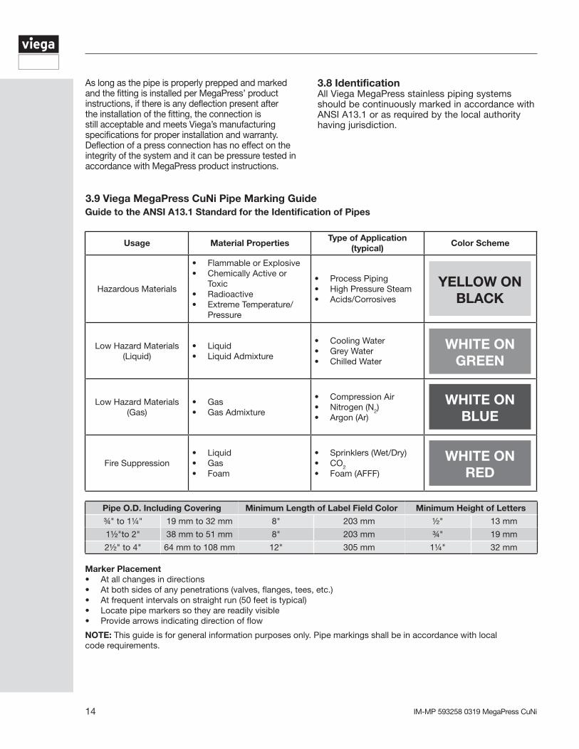
3.9 Viega MegaPress CuNi Pipe Marking GuideGuide to the ANSI A13.1 Standard for the Identification of Pipes
Usage Material PropertiesType of Application
(typical)Color Scheme
Hazardous Materials
• Flammable or Explosive• Chemically Active or
Toxic• Radioactive• Extreme Temperature/
Pressure
• Process Piping• High Pressure Steam• Acids/Corrosives
Low Hazard Materials (Liquid)
• Liquid• Liquid Admixture
• Cooling Water• Grey Water• Chilled Water
Low Hazard Materials (Gas)
• Gas• Gas Admixture
• Compression Air• Nitrogen (N2)• Argon (Ar)
Fire Suppression• Liquid• Gas• Foam
• Sprinklers (Wet/Dry)• CO2
• Foam (AFFF)
Pipe O.D. Including Covering Minimum Length of Label Field Color Minimum Height of Letters
¾" to 1¼" 19 mm to 32 mm 8" 203 mm ½" 13 mm
1½"to 2" 38 mm to 51 mm 8" 203 mm ¾" 19 mm
2½" to 4" 64 mm to 108 mm 12" 305 mm 1¼" 32 mm
Marker Placement• At all changes in directions• At both sides of any penetrations (valves, flanges, tees, etc.)• At frequent intervals on straight run (50 feet is typical)• Locate pipe markers so they are readily visible• Provide arrows indicating direction of flow
NOTE: This guide is for general information purposes only. Pipe markings shall be in accordance with local code requirements.
YELLOW ON BLACK
WHITE ON GREEN
WHITE ON BLUE
WHITE ON RED
3.8 IdentificationAll Viega MegaPress stainless piping systems should be continuously marked in accordance with ANSI A13.1 or as required by the local authority having jurisdiction.
As long as the pipe is properly prepped and marked and the fitting is installed per MegaPress’ product instructions, if there is any deflection present after the installation of the fitting, the connection is still acceptable and meets Viega’s manufacturing specifications for proper installation and warranty. Deflection of a press connection has no effect on the integrity of the system and it can be pressure tested in accordance with MegaPress product instructions.

15IM-MP 593258 0319 MegaPress CuNi
3.10 Viega MegaPress CuNi fitting system ½" to 2" installation
1
8a
9a
8b
9b
32
8c
9c
4 5
10
d
766
Pipe Diameter (in) d (in) d (mm)½ 3/16 5¾ 3/16 51 3/16 5
1¼ ⅜ 101½ ⅜ 102 ⅜ 10
Pipe Size (in) Insertion Depth (in)½ 11/16
¾ 13/16
1 1⅜1¼ 1⅞1½ 1⅞2 2
1 Cutpipingatrightanglesusingdisplacementtypecutter.2 Keependofpipingaminimumof4"awayfromthecontactareaofthevisetopreventpossibledamagetothepipinginthepressarea.SeeMegaPressManualforminimumclearancerequiredforpreptools.
3 Removeburrfrominsideandoutsideofpipingandpreptoproperinsertiondepthusingapreparationtoolorfinegritsandpaper.
4 Checksealandgripringforcorrectfit.Donotuseoilsorlubricants.
5 Illustrationdemonstratesproperfitofgripring,separationringandsealingelement.
6 Markproperinsertiondepth.Improperinsertiondepthmayresultinanimproperseal.Thedepthmarkingshallbevisibleonthecompletedassembly.
7 Refertochartforminimumdistancebetweenfittings.Toensureacorrectpress,aminimumdistancebetweenpressfittingsmustbemaintained.Failuretoprovidethisdistancemayresultinanimproperseal.
8a ViegaMegaPress½"-1"fittingconnectionsmustbeperformedwithMegaPressJaws.SeeRIDGIDOperator’sManualforpropertoolinstructions.
8bOpentheMegaPressJawandplaceatrightanglesonthefitting.Visuallycheckinsertiondepthusingmarkonpiping.
8c Startpressingprocessandholdthetriggeruntilthejawhasengagedthefitting.
9a ViegaMegaPress1¼"-2"fittingconnectionsmustbeperformedwithMegaPressRingsandV2Actuator.SeeOperator’sManualforpropertoolinstructions.
9b OpenMegaPressRingandplaceatrightanglesonthefitting.MegaPressRingmustbeengagedonthefittingbead.Checkinsertiondepth.
9c PlaceV2ActuatorontoMegaPressRingandstartpressingprocess.HoldthetriggeruntiltheActuatorhasengagedtheMegaPressRing.
10 RemoveMegaPressJawfromfittingorreleaseV2ActuatorfromRIDGIDMegaPressRingandthenremoveMegaPressRingfromthefittingoncompletionofpress.Removecontrollabeltoindicatepresshasbeencompleted.
DANGER!Read and understand all instructions for installing Viega MegaPress fittings. Failure to follow all
instructions may result in extensive property damage, serious injury or death.
Warning! Keep extremities and foreign objects away from press tool during pressing operation to prevent injury or incomplete press.

IM-MP 593258 0319 MegaPress CuNi 16
3.11 Viega MegaPress CuNi XL fitting system 2½" to 4" installation
1
7 8
32
9
4
10
5
x2-3
11
66
Insertion Depth (in) d (in) d (mm)2½ 113/16 463 25/16 594 3⅛ 80
1 Cutpipingatrightanglesusingdisplacementtypecutter.2 Keependofpipingaminimumof4"awayfromthecontactareaofthevisetopreventpossibledamagetothepipinginthepressarea.SeeMegaPressManualforminimumclearancerequiredforpreptools.
3 Removeburrfrominsideandoutsideofpipingandpreptoproperinsertiondepthusingapreparationtoolorfinegritsandpaper.
4 Illustrationdemonstratesproperfitofgripring,separationringandsealingelement.
5 Markproperinsertiondepth.Improperinsertiondepthmayresultinanimproperseal.Thedepthmarkingshallbevisibleonthecompletedassembly.
Warning! Keep extremities and foreign objects away from press tool during pressing operation to prevent injury or incomplete press.
6 Whileturningslightly,slidefittingontotubingtothemarkeddepth.Endoftubingmustcontactstop.
7 ViegaMegaPress2½"-4"fittingconnectionsmustbemadeusingMegaPressXLRingsandaPressBooster/Z3actuator.SeeOperator’sManualforpropertoolinstructions.
8 OpenMegaPressRingandplaceatrightanglesonthefitting.MegaPressRingmustbeengagedonthefittingbead.Checkinsertiondepth.
9 Removetheretainingboltofthepressmachine.SlidethePressBoosterinviathepressjawfixture.
10 PlacePressBooster/Z3actuatorontoMegaPressXLRingsandstartpressingprocess.HoldthetriggeruntiltheActuatorhasengagedtheMegaPressRing.
11 ThePressBoosterrequirestwopressesofthetriggertoexecuteacompletepress.Athirdpressmaybeneededtoinitiateareleasecycletoresettherollersbacktotheoriginalposition.

17IM-MP 593258 0319 MegaPress CuNi
Notes

IM-MP 593258 0319 MegaPress CuNi 18
Notes

19IM-MP 593258 0319 MegaPress CuNi
4 Warranty
Subject to the terms and conditions of this Limited Warranty, Viega LLC (Viega) warrants to end users, installers and distribution houses that its Viega metal press products (Viega product) when properly installed in approved marine applications and other products sold by Viega LLC when properly installed in marine applications in accordance with our listings shall be free from failure caused by manufacturing defects for a period of two (2) years from date of installation. This warranty applies only to approved applications. Installations that are not approved shall not be covered by this warranty and shall not be the responsibility of Viega LLC.
Under this Limited Warranty, you only have a right to a remedy if the failure or leak resulted from a manufacturing defect in the Viega product and the failure or leak occurs during the warranty period. You do not have a remedy under this warranty and the warranty remedy does not apply if the failure or any resulting damage is caused by (1) components other than those sold by Viega; (2) not designing, installing, inspecting, testing, or maintaining the Viega product in accordance with Viega’s installation and product instructions in effect at the time of installation and other specifications and approvals applicable to the installation; (3) improper handling and protection of the Viega product prior to, during and after installation, inadequate freeze protection, or exposure to environmental or operating conditions not recommended for the application; or (4) acts of nature, such as, but not limited to earthquakes, fire, or weather damage. Final approval as to use compatibility to a specific process or fluid application is the responsibility of the engineer of record or responsible design/facilities personnel and this Limited Warranty only applies to manufacturing defects in the Viega Product.
In the event of a leak or other failure in the Viega product covered by this warranty, it is the responsibility of the end user to take appropriate measures to diminish any damage, to include making timely repairs. Only if the warranty applies
Viega Limited Warranty for Marine ApplicationsMarine applications are defined as mobile structures
used to navigate water or stationary structures in water
will Viega be responsible for the remedy under this warranty. The part or parts which you claim failed should be kept and Viega contacted by writing to the address below or telephoning 1-800-976-9819 within thirty (30) calendar days after the leak or other failure and identifying yourself as having a warranty claim. You should be prepared to ship, at your expense, the product which you claim failed due to a manufacturing defect, document the date of installation, and the amount of the repair or replacement if performed by you. Within a reasonable time after receiving the product, Viega will investigate the reasons for the failure, which includes the right to inspect the product at a Viega location and reasonable access to the site of damage. Viega will notify you in writing as to the results of its review.
In the event that Viega determines that the failure or leak was the result of a manufacturing defect in the Viega Product covered by this warranty and to which this warranty applies, the EXCLUSIVE AND ONLY REMEDY under this warranty shall be the reimbursement for reasonable charges for repair or replacement of the Viega Product itself. VIEGA SHALL NOT BE LIABLE FOR CONSEQUENTIAL OR OTHER DAMAGE (FOR EXAMPLE, ECONOMIC LOSS, WATER OR PROPERTY OR MOLD REMEDIATION) UNDER ANY LEGAL THEORY AND WHETHER ASSERTED BY DIRECT ACTION, FOR CONTRIBUTION OR INDEMNITY OR OTHERWISE.
THE ABOVE WARRANTY IS IN LIEU OF ALL OTHER WARRANTIES, EXPRESS OR IMPLIED, INCLUDING, BUT NOT LIMITED TO, THE IMPLIED WARRANTIES OR ANY STATUTE OF LIMITATIONS RELATING TO SUCH WARRANTIES. Other than this Limited Warranty, Viega does not authorize any person or firm to create for it any other obligation or liability in connection with its products.
This Limited Warranty gives you specific legal rights and you also may have other rights which may vary from state to state. This warranty shall be interpreted and applied under the law of the state in which the product is installed and is intended as a Commercial Warranty.

IM-MP 593258 0319 MegaPress CuNi
Viega LLC585 Interlocken Blvd. Broomfield, CO 80021 Phone (800) 976-9819 www.viega.us
This document is subject to updates. For the most current Viega technical literature please visit www.viega.us.©2019, Viega®, FostaPEX®, GeoFusion®, ManaBloc®, MegaPress®, ProPress®, Radiant Wizard®, SeaPress®, Smart Connect®, Climate Mat®, Climate Panel®, Climate Trak®, PureFlow®, XL®, Visign®, Visign for Style®, Visign for More®, Visign for Care®, and Visign for Public® are registered trademarks of Viega GmbH & Co. KG. SmartLoop®, Viega Eco Plus®, and Viega: Connected in quality® are trademark of Viega Holding GmbH & Co. KG. XL-C® is a registered trademark of Viega LLC. Eco Brass® is a registered trademark of Mitsubishi Shindoh Co., LTD. RIDGID® is a registered trademark of RIDGID, Inc. LoopCAD® is a registered trademark of Avenir Software Inc. Radel® R is a registered trademark of Solvay Advanced Polymers, LLC. LEED® is a registered trademark of the U.S. Green Building Council®.