vienna lte-a simulators, link level uplink simulator documentation · 2016-12-13 · vienna lte-a...
TRANSCRIPT

1
Vienna LTE-A SimulatorsLTE-A Uplink Link Level Simulator
Documentation, v1.6Institute of Telecommunications
TU Wien, AustriaGusshausstrasse 25/389, A-1040 Vienna, Austria
Web: http://www.nt.tuwien.ac.at/ltesimulator
Abstract
This document contains documentation on how to use the Long Term Evolution Advanced (LTE-A) Uplink Link Levelsimulator [1] from the Vienna LTE-A simulator suite, as well as some insight on its structure and the assumptions that weremade while developing it. This document gives an introduction on how to use the simulator. The concept and the structure of thesimulator is described in more detail in [2] and in [3].
I. FOREWORD
The LTE-A Uplink Link Level simulator is published under a non-commercial academic use license. Please make sure thatyou understand the terms and conditions of the license before you use any of the available software packages. Would yourequire a license different to a non-commercial academic one please contact Stefan Schwarz, Stefan Pratschner.
The detailed license agreement for the LTE-A Uplink Link Level simulator can be found in Section XVII. Please read thelicense agreement carefully, as parts of the code are under the GNU Lesser General Public License [4], and the MIT License [5].

2
CONTENTS
I Foreword 1
II Running the simulator for the first time 3
III MEX files 5
IV Running your own simulations 5
V Simulation parameters 5V-A General parameters . . . . . . . . . . . . . . . . . . . . . . . . . . . . . . . . . . . . . . . . . . . . . . 5V-B eNodeB specific parameters . . . . . . . . . . . . . . . . . . . . . . . . . . . . . . . . . . . . . . . . . . 6V-C User Equipment (UE) specific parameters . . . . . . . . . . . . . . . . . . . . . . . . . . . . . . . . . . 7V-D UE feedback specific parameters . . . . . . . . . . . . . . . . . . . . . . . . . . . . . . . . . . . . . . . 7V-E Channel model parameters . . . . . . . . . . . . . . . . . . . . . . . . . . . . . . . . . . . . . . . . . . 8V-F Channel matrix source . . . . . . . . . . . . . . . . . . . . . . . . . . . . . . . . . . . . . . . . . . . . 9V-G Scheduler parameters . . . . . . . . . . . . . . . . . . . . . . . . . . . . . . . . . . . . . . . . . . . . . 9
VI More Reference simulations 9
VII Running multiple simulations: multisim 12VII-A Example . . . . . . . . . . . . . . . . . . . . . . . . . . . . . . . . . . . . . . . . . . . . . . . . . . . . 12VII-B Usage . . . . . . . . . . . . . . . . . . . . . . . . . . . . . . . . . . . . . . . . . . . . . . . . . . . . . . 12
VIII Note on parallel simulations and random number generation 13
IX Changelog 13
X Referencing 14
XI Known issues 14
XII Using the Winner Phase II channel model reference implementation 14
XIII Using the 3D Channel Model from TR 36.873 14
XIV Questions 17
XV Mailing List 17
XVI The People (so far) behind the development of the simulator 17
XVII License agreement 17XVII-A Academic Usage . . . . . . . . . . . . . . . . . . . . . . . . . . . . . . . . . . . . . . . . . . . . . . . . 17XVII-B Grant of copyright license . . . . . . . . . . . . . . . . . . . . . . . . . . . . . . . . . . . . . . . . . . 17XVII-C Grant of source code license . . . . . . . . . . . . . . . . . . . . . . . . . . . . . . . . . . . . . . . . . 17XVII-D Exclusions from license grant . . . . . . . . . . . . . . . . . . . . . . . . . . . . . . . . . . . . . . . . . 18XVII-E Warranty of provenance and disclaimer of warranty . . . . . . . . . . . . . . . . . . . . . . . . . . . . . 18XVII-F Limitation of liability . . . . . . . . . . . . . . . . . . . . . . . . . . . . . . . . . . . . . . . . . . . . . 18XVII-G Termination . . . . . . . . . . . . . . . . . . . . . . . . . . . . . . . . . . . . . . . . . . . . . . . . . . 18XVII-H Open source and code under other license terms . . . . . . . . . . . . . . . . . . . . . . . . . . . . . . 18XVII-I Publication of Your contact data . . . . . . . . . . . . . . . . . . . . . . . . . . . . . . . . . . . . . . . 18XVII-J Appendix I . . . . . . . . . . . . . . . . . . . . . . . . . . . . . . . . . . . . . . . . . . . . . . . . . . . 18
XVIII Acknowledgment 18
References 19
List of Figures 20
List of Tables 20

3
II. RUNNING THE SIMULATOR FOR THE FIRST TIME
The LTE-A Link Level Uplink simulator is provided with several test simulation scenarios that can be used to verify that thesimulator runs in the expected way.
To verify that the simulator is working properly you can execute the LTE_UL_quicktest MATLAB script. This scriptcontains three simulations. Two simulations should test the performance of a single user LTE-A transmission on an uncorrelatedTU channel for several transmission modes [6] and antenna configurations (number of transmit antennas Nt times numberof receive antennas Nr). All simulated transmission modes (Single-Input Single-Output (SISO) and Closed Loop SpatialMultiplexing (CLSM)) utilize UE feedback to adapt important transmission parameters (code rate, modulation alphabet, Multiple-Input Multiple-Output (MIMO) preprocessing) to the channel quality (see [7] for details). The third simulation shows theMUMIMO capability of the simulator.
The first simulation contains three subsimulations with a different number of receiver antennas (1, 2 and 4) and the resultsare shown in Figure 1a. The second simulation compares the SISO case to different MIMO scenarios and should produce theresults shown in Figure 1b. Lastly the third simulation compares the performance of 4 users with 4 antennas each connected toa base station with 4 receive antennas (CLSM) applying single user MIMO and 4 users equiped with antenna one antenna eachin the Multi User Multiple-Input Multiple-Output (MU-MIMO) transmission mode. The results are shown in Figure 2.
SNR [dB]-10 0 10 20 30 40
thro
ughp
ut [M
bit/s
]
0
0.5
1
1.5
2
2.5
3
3.5
4
4.5
1x11x21x4
(a) receive Diversity
SNR [dB]-10 0 10 20 30 40
thro
ughp
ut [M
bit/s
]
0
2
4
6
8
10
12
14
16
18
SISOCLSM 2x2CLSM 2x4CLSM 4x4
(b) MIMO
Fig. 1: First two plots resulting from running the LTE_UL_quicktest.m, MATLAB script. 1.4 MHz, TU channel, zero-delayfeedback, single user.
0 5 10 15 20 25 30 35 40
SNR [dB]
0
2
4
6
8
10
12
14
16
18
cell
thro
ughp
ut [M
bit/s
]
CLSMMUMIMO
Fig. 2: Third plot produced by LTE_UL_quicktest.m - shows MU gain in the cell throughput. In both cases 4 users aresimulated. While in the MIMO case the users are scheduled with round robin in the MU-MIMO case all users are transmittingsimultaneously.
The basic parameters are defined in the configuration scripts doc_simo.m, doc_mimo.m and doc_mumimo.m in the./examples/ directory. The rest of the parameters are loaded from the parameter script./examples/load_params_doc_antenna. For the plots We set the number of subframes to 50 (20 in the MU-MIMO

4
case) in the release version of the quicktest file (even at this number especially the 4x4 configuration needs quite some time).Due to the small number of subframes the results might differ a bit from the ones in the documentation which can also beseen from the plotted confidence intervals. If you want a faster simulation you can decrease the number of subframes in theconfiguration files by setting simulation.N_subframes to a smaller number. If you want slower but more accurate resultsyou need to increase the number of subframes and probably consider running the simulation over night.
Parameter ValueNumber of UEs 1
Bandwidth 1.4 MHzHARQ Retransmissions 0
Uplink delay noneChannel type TU uncorrelated
Filtering Block FadingReceiver type MMSE
Simulation length 50 (2000) subframesTransmit modes 1×1, 1×2, 1×4, CLSM 2×2, 2×4, 4×4, MUMIMO 1×4
TABLE I: Basic settings used in the LTE_UL_quicktest.m

5
III. MEX FILES
Computation-intensive parts of the LTE-A Uplink Link Level simulator are implemented in C and used in the simulator bymeans of MEX files. The source code for the given files can be found in the /C-source folder under the simulator root folder.Please note that some of the functions there are licensed under other license terms. Please check Section XVII for more details.
The MEX files distributed with the simulator release are the Windows 64-bit version. Should you require them for anyother platform you recompile them by using the LTE_aux_mex_files script. You can find more information on how touse/write/compile MEX files at http://www.mathworks.com/support/tech-notes/1600/1605.html.
IV. RUNNING YOUR OWN SIMULATIONS
While the LTE_UL_quicktest MATLAB script is adequate to see if the simulator produces reasonable results, you mightneed more flexibility than given by this.
If you want to start creating your own simulations you can check the LTE_UL_sim_batch.m script. It provides the meansto set basic simulation parameters (SNR range, number of subframes simulated, choice of simulation configuration) and callsall necessary scripts in the appropriate order.
Below you can find a list of exemplary parameters that you may want to configure in the batch file:• cqi_vec: set of Modulation and Coding Schemes (MCSs) that are used for the simulation. In [8], 15 different Channel
Quality Indicators (CQIs) are specified. If you want to simulate with all possible CQIs, just set the cqi_i loop to runover [1:15]. Usually you want to set this to a single CQIs to do only one simulation. This is especially useful ifyou use CQI-Feedback (i.e. LTE_params.UE_config.CQI_fb = true) to determine the CQI value automaticallydepending on the current channel conditions.
• N_subframes: the length of the simulation, or how many subframes (Transmission Time Intervals (TTIs)) are simulatedfor each value of cqi_i and SNR_vec.
• SNR_vec: a vector containing the average Signal to Noise Ratios (SNRs) that will be used for each simulation run. Allusers will experience the same average SNR.
• LTE_UL_load_parameters: load the parameter file that configures the simulator. A more detailed description of theavailable configuration parameters can be found in Section V.
• LTE_UL_sim_main: main routine of the simulator.• Generate the output filename and save the results in a .mat file.
V. SIMULATION PARAMETERS
Below you can find a list of the parameters that can be configured in LTE_UL_load_parameters
A. General parameters
• LTE_params.nUE: Number of UEs per eNodeB to simulate. Each eNodeB serves LTE_params.nUE UEs. The totalnumber of users is therefore LTE_params.nBS · LTE_params.nUE.
• LTE_params.nBS: Number of eNodeBs (cells) that will be simulated.• LTE_params.downlink_delay: the delay the downlink experiences. It applies to ACKnowledgments (ACKs), CQI,
Precoding Matrix Indicator (PMI) and Rank Indicator (RI) reports.• LTE_params.show_plots: whether plots are shown after the simulation or not.• LTE_params.to_plot: a cell array containing the plots that shall be shown after the simulation completes. If for
example {’throughput_user’,’bler_user’} is given only the throughput and block error plots are shown. Passingan empty array (eg. {}) all available plots are displayed. All plots can be produced at a later point in time by usingLTE_UL_plot_results(simulation_results, LTE_params).
• LTE_params.confidence_interval_probability specifies the probability that your results lie in the displayedconfidence interval. By using the default value 0.95 the confidence interval marks the interval where 95% of the resultsare expected (assuming the result interpreted as a random variable is Gaussian). If no confidence intervals are required setthis parameter to 0. This option makes use of bootci, if this function is not available to you set this parameter to 0.
• LTE_params.carrier_freq_UP: carrier center frequency [Hz]• LTE_params.Bandwidth: system bandwidth. Allowed values are 1.4 MHz, 3 MHz, 5 MHz, 10 MHz, 15 MHz, and
20 MHz. This bandwidths are equivalent to 6, 15, 25, 50, 75, and 100 Resource Blocks (RBs) respectively. Carrieraggregation (to enable bandwidths > 20 MHz) is currently not supported by the LTE-A simulator.
• LTE_params.HARQ_processes: number of parallel Hybrid-ARQ (HARQ) processes. The maximum value, accordingto [9] is 8.
• LTE_params.max_HARQ_retransmissions: maximum number of HARQ retransmissions, not including the originaltransmission. This feature is currently not supported.
• LTE_params.SubcarrierSpacing: in Hz, 15 kHz only for uplink.

6
• LTE_params.CyclicPrefix: cyclic prefix length [10]. Either normal or extended.• LTE_params.DFT_spreading_off: Turns off the DFT spreading in the SC-FDMA modulation when set to true.
This leads to a OFDM like (downlink) performance in some sense.• LTE_params.simulation_method: the simulator is capable of using the MATLAB Parallel Toolbox in order to
speed up simulations by using parfor loops. If you happen to have the Distributed Computing Toolbox, you will also beable to make use of it by using this option. Set this variable to parallel or normal to parallelize the SNR loop inLTE_sim_main or just perform a single-core simulation. Keep in mind that some modifications you do to the code maynot work in the parallel version or may directly cause it not to run.
• LTE_params.simulate_with_all_zero_sequences: true if you want that the transmitted data is an all-zerosequence (useful for interleaver testing and debugging).
• LTE_params.random_noise_seeding: whether the seed for the random number generator that generates the noiseis set (allows for repeatability of the noise realizations).
• LTE_params.noise_seed: Only used if the upper variable is set to true. Integer number that sets the randomnumber seed of the noise random number generator.
• LTE_params.connection_table specifies which user is attached to which eNodeB (BS). This parameter is a matrixwith nBS rows and nUE·nBS columns of 0 and 1. A 1 in row r and column c ensures that UE number c (global numbering)is attached to BS r, while 0 stands for not connected. Not that every eNodeB needs to have the same number of UEs.In most cases setting the parameter by calling utils.generate_connection_table(nBS, nUE) will be suffi-cient.
• LTE_params.pathloss_matrix this parameter is a matrix of the same dimensions LTE_params.connection_table.The entries determine how much the signal from BS r to UE c is attenuated in dB.Usually it makes sense to use utils.generate_pathloss_matrix(LTE_params.connection_table, loss)to set this parameter. This attenuates the interference of other base stations by loss dB. If loss is set to inf nointerference is present and the base stations do not
B. eNodeB specific parameters
• LTE_params.BS_config.receiver: either ZF for a Zero Forcing (ZF) receiver or MMSE for a Minimum MeanSquare Error (MMSE) receiver. An additional option is the IAMMSE receiver which considers the interference of other BSin the detection process. This receiver only works with perfect channel knowledge and in UE_config.mode 1.
• LTE_params.BS_config.nRX: number of receive antennas at the eNodeB.• LTE_params.BS_config.channel_estimation_method: Currently the following channel estimators are avail-
able for LTE-A:– PERFECT: Perfect channel knowledge at the receiver is used.– LS_AV: A least squares based channel estimation method.– LS_SAV: An improved least squares based channel estimation method.– LS_QS: A least squares based estimator applying a Quadratic Smoothing.– DFT: A DFT based channel estimation method from [11].– MMSE: A MMSE channel estimator.– MMSE_2D: A 2 dimensional MMSE channel estimator with MMSE interpolation in time and frequency domain. For
this, the parameter LTE_params.BS_config.channel_interpolation_method also needs to be set toMMSE_2D.
• LTE_params.BS_config.channel_estimation_frequency_smoothing: In case of the LS_QS channelestimator, this parameter determines the degree of smoothing in the frequency domain. It is dependent on the number ofused Layers in case of spatial multiplexing.
• LTE_params.BS_config.channel_interpolation_method: This parameter determines how the channel isinterpolated between the pilot positions for estimating a FastFading (time variant) channel. Currently available optionsare flat (flat channel in each slot), linear, pchip (for a cubic interpolation in Matlab), spline, DPSS or MMSE_2D.Note that this parameter only affects the channel estimation for a FastFading simulation. In case of a BlockFadingsimulation, the two channel estimates from two slots are averaged for noise reduction as the channel is constant in time(for the whole subframe).
• LTE_params.BS_config.channel_prediction: If set to true, the wireless channel is predicted according to amethod selected by the parameter LTE_params.BS_config.channel_interpolation_method. This predictedwireless channel is than exploited for calculation of feedback parameters ( CQI, PMI and RI). By this, feedback delayspecified by LTE_params.downlink_delay can be partly compensated.
• LTE_params.BS_config.channel_interpolation_past_points: In case of a FastFading simulation,this sets the number of channel estimates that are used for time interpolation in addition to the channel estimates of the

7
current subframe. Th number is given in previously transmitted slots. As the current subframe consists of two slots, a valueof e.g. 1 would mean that one additional slot is used for interpolation resulting in three channel estimates that are used.
• LTE_params.BS_config.autocorrelation_matrix_type: type of autocorrelation matrix. Currently onlyideal is supported.
• LTE_params.BS_config.realization_num: number of channel realizations. Used for averaging to obtain thechannel autocorrelation matrix.
• LTE_params.BS_config.realization_num_total: number of channel realizations are used just for the esti-mation of the autocorrelation matrix.
• LTE_params.BS_config.turbo_iterations: Number of iterations of the turbo decoder. Set by default to 8.
C. UE specific parameters
• LTE_params.UE_config.mode: the transmission modes are defined in TS 36.213 V11.4 Section 8.0 [12]. However,the numbering of the implemented transmission modes is done as in the downlink. Additionally we added a transmissionmode 5 which applies MUMIMO with one transmit antenna.
– 1: single transmit antenna– 4: Closed Loop Spatial Multiplexing– 5: MUMIMO
• LTE_params.UE_config.user_speed: UE speed in m/s. Please note that this parameter has no effect for thesetting: LTE_params.ChanMod_config.filtering = ’BlockFading’ andLTE_params.ChanMod_config.time_correlation=’independent’.
D. UE feedback specific parameters
• LTE_params.UE_config.MCS_and_scheduling_CSI: Weather the channel that is employed for calculating thelink adaptation and scheduling is perfect or estimated. If set to true, still the estimated channel will be employed tocalculate the linear receiver. Please note, that in case of LTE_params.BS_config.channel_estimation_method=’perfect’,also perfect channel knowledge is exploited for the link adaptation and scheduling. Further, for LTE_params.downlink_delay=0also the perfect channel knowledge will be exploited, as the link adaptation and scheduling has to be known beforetransmission, which would be impossible for instantaneous downlink feedback.
• LTE_params.UE_config.PMI_fb: Whether PMI feedback is activated or not (true/false).• LTE_params.UE_config.RI_fb: Whether RI feedback is activated or not (true/false).• LTE_params.UE_config.CQI_fb: Whether CQI feedback is activated or not true/false). When set to false
the CQI value from the batch file LTE_UL_sim_batch.m is used, as explained in Section IV.• LTE_params.UE_config.PMI: PMI value used when LTE_params.UE_config.PMI_fb is set to false. Has
to be zero if LTE_params.UE_config.PMI_fb is false and LTE_params.UE_config.RI_fb is true. Hasto be a valid codebook entry if LTE_params.UE_config.PMI_fb and LTE_params.UE_config.RI_fb arefalse.
• LTE_params.UE_config.RI: RI value used when LTE_params.UE_config.RI_fb is set to false.• LTE_params.UE_config.SINR_averaging.averager: defines the Effective Signal to Interference and Noise
Ratio Mapping (ESM) averager used. Possible values are EESM, MIESM, or HARM_MEAN.• LTE_params.UE_config.SINR_averaging.EESMbetas: defines the calibration factors required for Exponential
Effective Signal to Interference and Noise Ratio Mapping (EESM). Those values are obtained from extensive trainingsimulations and should not be changed.
• LTE_params.UE_config.SINR_averaging.MIESMbetas: defines the calibration factors required for MutualInformation Effective Signal to Interference and Noise Ratio Mapping (MIESM). Those values are obtained from extensivetraining simulations and should not be changed.
• LTE_params.UE_config.SINR_averaging.MCSs: defines the used MCS set. Modification of these values mightlead to unexpected behavior, as the calibration factors (EESMbetas and MIESMbetas) are not trained for other MCSs.
• LTE_params.UE_config.nTX: number of transmit antennas at the UE.• LTE_params.UE_config.ignore_channel_estimation: whether the channel estimation mean square error is
taken into account during the feedback calculation or not. If channel estimation is activated, the option should be set totrue, otherwise the performance of the system might be overestimated.
• LTE_params.UE_config.channel_averaging: whether channel averaging is used during feedback calculationor not. If set to true just a single average channel value per resource block is used to compute the feedback for complexityreduction. Especially in ≥ 4× 4 systems this degrades the performance of the feedback method.
• LTE_params.UE_config.ignore_ISI_ICI: weather the feedback takes ISI and ICI caused by insufficient cyclicprefix length into account or not.

8
• LTE_params.UE_config.N_soft: Defines the total number of soft channel bits available for HARQ processing (TS36.306 4.2.1.3 [13]).
E. Channel model parameters
Parameters that configure how the channel is generated and the signal filtered.• LTE_params.ChanMod_config.filtering: BlockFading for a channel that is constant during one subframe
or FastFading for a channel that varies in time within a subframe.• LTE_params.ChanMod_config.time_correlation: Sets whether the channel realizations are time-correlated
or not. correlated or independent.• LTE_params.ChanMod_config.corr_coefRX: Correlation between the receiver antennas. Only compatible with
block fading filtering. This parameter might be overwritten in the LTE_UL_load_parameters_generate_elementsscript file.
• LTE_params.ChanMod_config.corr_coefTX: Correlation between the transmitter antennas. Only compatible withblock fading filtering. This parameter might be overwritten in the LTE_UL_load_parameters_generate_elementsscript file.
• LTE_params.ChanMod_config.interpolation_method: Channel interpolation method for the channel genera-tion in the simulator. Either shift_to_nearest_neighbor for nearest neighbor interpolation or sinc_interpolationfor sinc interpolation, which is more precise. Necessary if the channel sampling rate is not equal to the sampling rate ofthe transmit signal.
• LTE_params.ChanMod_config.sin_num: specifies the number of sin realizations used for the modified Rosa-Zhengmodel [14], [15].
• LTE_params.ChanMod_config.tau_rms: Is the RMS delay spread of the ePDP channel model.• LTE_params.ChanMod_config.type: specifies the type of channel used. The available ones are:
– AWGN: Additive White Gaussian Noise channel.– flat Rayleigh: temporally uncorrelated frequency flat Rayleigh fading channel.– Tap-delay based models: PedA, PedB, PedBcorr, VehA, VehB, TU, RA, ePDP, and HT [16], [17].– Externally-generated channel coefficients: winner_II. Uses the publicly-available Winner II implementation to
generate the channel coefficients [18]. The following parameters can be configured when using the Winner II channelmodel.∗ LTE_params.ChanMod_config.winner_settings.Scenario: 1=A1, 2=A2, 3=B1, 4=B2, 5=B3, 6=B4,
7=B5a, 8=B5c, 9=B5f, 10=C1, 11=C2, 12=C3, 13=C4, 14=D1 and 15=D2a.∗ LTE_params.ChanMod_config.winner_settings.PropagCondition: LOS or NLOS.∗ LTE_params.ChanMod_config.winner_settings.SampleDensity: number of time samples per half
wavelength∗ LTE_params.ChanMod_config.winner_settings.UniformTimeSampling: use same time sampling
grid for all links (yes or no).∗ LTE_params.ChanMod_config.winner_settings.FixedPdpUsed: nonrandom path delays and pow-
ers (yes or no).∗ LTE_params.ChanMod_config.winner_settings.FixedAnglesUsed: nonrandom AoD/AoAs (yes
or no).∗ LTE_params.ChanMod_config.winner_settings.PolarisedArrays: usage of dual polarised arrays
(yes or no).∗ LTE_params.ChanMod_config.winner_settings.TimeEvolution: usage of time evolution (yes orno).
∗ LTE_params.ChanMod_config.winner_settings.PathLossModelUsed: usage of path loss model(yes or no).
∗ LTE_params.ChanMod_config.winner_settings.ShadowingModelUsed: usage of shadow fadingmodel (yes or no).
∗ LTE_params.ChanMod_config.winner_settings.PathLossModel: path loss model function name(pathloss).
∗ LTE_params.ChanMod_config.winner_settings.PathLossOption: Available options are CR_light,CR_heavy, RR_light, RR_heavy. CR=Corridor-Room, RR=Room-Room NLOS.
∗ LTE_params.ChanMod_config.winner_settings.RandomSeed: sets a random seed. Can be left empty.∗ LTE_params.ChanMod_config.winner_settings.UseManualPropCondition: whether to use man-
ual propagation condition (LOS/NLOS) settings or not (yes or no). If not, the propagation condition is drawnfrom probabilities.

9
F. Channel matrix source
• LTE_params.channel_matrix_source: Controls the generation of the channel matrix trace. generated togenerate it every time. trace to load it from a trace.
• LTE_params.store_channel_trace: false, the storing of the channel trace it not yet fully implemented.• LTE_params.channel_matrix_tracefile: filename of the trace file where the generated channel matrix trace is
stored. Only applicable if trace mode is used (if the mode is set to trace, the channel matrix is already read from atrace, so it is meaningless to save it again in another trace).
G. Scheduler parameters
• LTE_params.scheduler.type: Currently there are four schedulers implemented– fixed: A scheduler that employs a fixed predefined schedule from LTE_params.scheduler.fixed_scheduler_assignment.– fixed MU MIMO: A fixed scheduler for MU MIMO that schedules all users on the same time frequency resources.– max MU MIMO: A scheduler for MU MIMO that aims to maximize the sum throughput by exhaustive search over
all possible user assignment combinations.– random MU MIMO: A scheduler for MU MIMO that randomly selects a subset of users to be scheduled.– greedy MU MIMO: A scheduler for MU MIMO that aims for high sum throughput by selecting user assignment
combinations exploiting a greedy algorithm.– greedy MU MIMO: Similar to the– greedy MU MIMO scheduler, but picks users with the best Frobenius norm.– round robin: A round robin scheduler.– opt max Throughput: This scheduler selects the best possible schedule in terms of throughout by exhaustive
search. (currently only for SISO)– approx max Throughput: This scheduler heuristically tries to maximize the throughput by a heuristic algorithm.
(currently only for SISO)– best CQI: Scheduler that schedules users with the highest CQI values for a complete subframe.
• LTE_params.scheduler.fixed_scheduler_assignment: Defines the fixed schedule used when the fixedscheduler is selected. It is a column vector where the number of entries equals LTE_prams.nUE and each entry specifieshow many resource blocks a UE is assigned. Therefore all entries of this vector must sum to the total number of resourceblocks as defined by the simulation bandwidth LTE_params.Bandwidth.
VI. MORE REFERENCE SIMULATIONS
Besides the one mentioned on Section II, the simulator is provides two more reference simulations, which can be comparedwith the performance curves from 3GPP RAN documents such as [19] to cross-check the results of the simulator.LTE_UL_LTE_UL_AWGN_test runs two simulation and produces throughput and Block Error Ratio (BLER) curves for
each of them. The first simulation shows the results for the MCS defined in [8] (CQIs 1-15). The plots are shown in Figure 3.The second simulation runs with all the MCSs specified in R1-071967, page 16 [19] and the results are given in Figure 4.
The MCS, including the CQI value used in the simulator, the modulation and Effective Code Rate (ECR) used in each ofthe simulations are shown in Table II.

10
CQI Modulation ECR [19] ECRx1024
101 4QAM 1/9 114102 4QAM 1/6 171103 4QAM 0.21 215104 4QAM 1/4 256105 4QAM 1/3 314106 4QAM 0.42 430107 4QAM 1/2 512108 4QAM 0.58 594109 4QAM 2/3 683110 4QAM 0.73 748
111 16QAM 0.43 440112 16QAM 0.46 471113 16QAM 1/2 512114 16QAM 0.54 553115 16QAM 0.58 594116 16QAM 0.61 625117 16QAM 2/3 683118 16QAM 0.73 748119 16QAM 4/5 819
120 64QAM 0.58 594121 64QAM 0.62 635122 64QAM 2/3 683123 64QAM 0.70 717124 64QAM 0.74 758125 64QAM 4/5 819126 64QAM 0.85 870127 64QAM 0.90 922
CQI Modulation ECR ECRx1024 [8]
1 4QAM 0.0762 782 4QAM 0.1172 1203 4QAM 0.1885 1934 4QAM 0.3008 3085 4QAM 0.4385 4496 4QAM 0.5879 602
7 16QAM 0.3691 3788 16QAM 0.4785 4909 16QAM 0.6016 616
10 64QAM 0.4551 46611 64QAM 0.5537 56712 64QAM 0.6504 66613 64QAM 0.7539 77214 64QAM 0.8525 87315 64QAM 0.9258 948
TABLE II: MCSs used in LTE_UL_AWGN_test for R1-07196 (left) and for LTE (right)
SNR [dB]-10 -5 0 5 10 15 20
BLE
R
10 -3
10 -2
10 -1
10 0AWGN BLER 1.4 MHz, 2000 subframes
CQI 1CQI 2CQI 3CQI 4CQI 5CQI 6CQI 7CQI 8CQI 9CQI 10CQI 11CQI 12CQI 13CQI 14CQI 15
(a) BLER, AWGN no HARQ
SNR [dB]-10 -5 0 5 10 15 20
thro
ughp
ut [M
bit/s
]
0
0.5
1
1.5
2
2.5
3
3.5
4
4.5AWGN throughput 1.4 MHz, 2000 subframes
CQI 1CQI 2CQI 3CQI 4CQI 5CQI 6CQI 7CQI 8CQI 9CQI 10CQI 11CQI 12CQI 13CQI 14CQI 15
(b) Throughput, AWGN, no HARQ
Fig. 3: Reference BLER and throughput plots for the 15 MCSs defined in [8]

11
-10 -5 0 5 10 15 20
SNR [dB]
10 -3
10 -2
10 -1
10 0
BLE
R
AWGN BLER 1.4 MHz, 2000 subframesMCS 1: QPSK, 0.11MCS 2: QPSK, 0.17MCS 3: QPSK, 0.21MCS 4: QPSK, 0.25MCS 5: QPSK, 0.33MCS 6: QPSK, 0.42MCS 7: QPSK, 0.50MCS 8: QPSK, 0.58MCS 9: QPSK, 0.67MCS 10: QPSK, 0.73MCS 11: 16QAM, 0.43MCS 12: 16QAM, 0.46MCS 13: 16QAM, 0.50MCS 14: 16QAM, 0.54MCS 15: 16QAM, 0.58MCS 16: 16QAM, 0.61MCS 17: 16QAM, 0.67MCS 18: 16QAM, 0.73MCS 19: 16QAM, 0.80MCS 20: 64QAM, 0.58MCS 21: 64QAM, 0.62MCS 22: 64QAM, 0.67MCS 23: 64QAM, 0.70MCS 24: 64QAM, 0.74MCS 25: 64QAM, 0.80MCS 26: 64QAM, 0.85MCS 27: 64QAM, 0.90
(a) BLER, AWGN no HARQ
-10 -5 0 5 10 15 20
SNR [dB]
0
0.5
1
1.5
2
2.5
3
3.5
4
4.5
thro
ughp
ut [M
bit/s
]
AWGN throughput 1.4 MHz, 2000 subframesMCS 1: QPSK, 0.11MCS 2: QPSK, 0.17MCS 3: QPSK, 0.21MCS 4: QPSK, 0.25MCS 5: QPSK, 0.33MCS 6: QPSK, 0.42MCS 7: QPSK, 0.50MCS 8: QPSK, 0.58MCS 9: QPSK, 0.67MCS 10: QPSK, 0.73MCS 11: 16QAM, 0.43MCS 12: 16QAM, 0.46MCS 13: 16QAM, 0.50MCS 14: 16QAM, 0.54MCS 15: 16QAM, 0.58MCS 16: 16QAM, 0.61MCS 17: 16QAM, 0.67MCS 18: 16QAM, 0.73MCS 19: 16QAM, 0.80MCS 20: 64QAM, 0.58MCS 21: 64QAM, 0.62MCS 22: 64QAM, 0.67MCS 23: 64QAM, 0.70MCS 24: 64QAM, 0.74MCS 25: 64QAM, 0.80MCS 26: 64QAM, 0.85MCS 27: 64QAM, 0.90
(b) Throughput, AWGN, no HARQ
Fig. 4: Reference BLER and throughput plots for the 27 MCSs defined in [19]
12
VII. RUNNING MULTIPLE SIMULATIONS: MULTISIM
In Section II and Section IV we described how to run simulations using the simulator. This is the way to go if you want toevaluate the performance giving a single parameter set. In our experience it is often useful to quickly compare simulations fordifferent parameter values.
A. Example
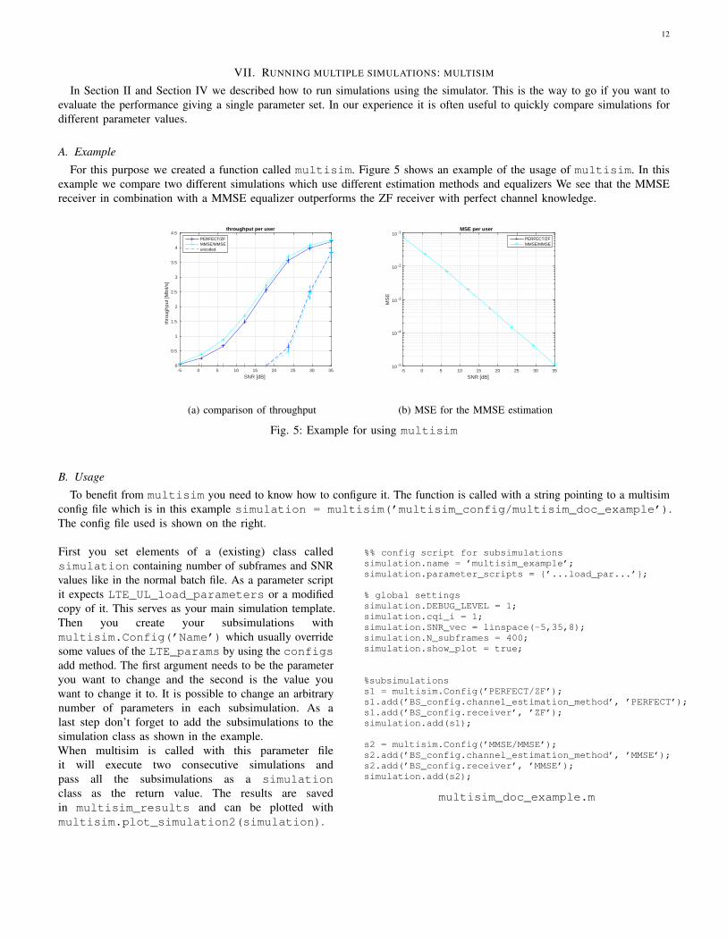
For this purpose we created a function called multisim. Figure 5 shows an example of the usage of multisim. In thisexample we compare two different simulations which use different estimation methods and equalizers We see that the MMSEreceiver in combination with a MMSE equalizer outperforms the ZF receiver with perfect channel knowledge.
SNR [dB]-5 0 5 10 15 20 25 30 35
thro
ughp
ut [M
bit/s
]
0
0.5
1
1.5
2
2.5
3
3.5
4
4.5throughput per user
PERFECT/ZFMMSE/MMSEuncoded
(a) comparison of throughput
SNR [dB]-5 0 5 10 15 20 25 30 35
MS
E
10 -5
10 -4
10 -3
10 -2
10 -1MSE per user
PERFECT/ZFMMSE/MMSE
(b) MSE for the MMSE estimation
Fig. 5: Example for using multisim
B. Usage
To benefit from multisim you need to know how to configure it. The function is called with a string pointing to a multisimconfig file which is in this example simulation = multisim(’multisim_config/multisim_doc_example’).The config file used is shown on the right.
First you set elements of a (existing) class calledsimulation containing number of subframes and SNRvalues like in the normal batch file. As a parameter scriptit expects LTE_UL_load_parameters or a modifiedcopy of it. This serves as your main simulation template.Then you create your subsimulations withmultisim.Config(’Name’) which usually overridesome values of the LTE_params by using the configsadd method. The first argument needs to be the parameteryou want to change and the second is the value youwant to change it to. It is possible to change an arbitrarynumber of parameters in each subsimulation. As alast step don’t forget to add the subsimulations to thesimulation class as shown in the example.When multisim is called with this parameter fileit will execute two consecutive simulations andpass all the subsimulations as a simulationclass as the return value. The results are savedin multisim_results and can be plotted withmultisim.plot_simulation2(simulation).
%% config script for subsimulationssimulation.name = ’multisim_example’;simulation.parameter_scripts = {’...load_par...’};
% global settingssimulation.DEBUG_LEVEL = 1;simulation.cqi_i = 1;simulation.SNR_vec = linspace(-5,35,8);simulation.N_subframes = 400;simulation.show_plot = true;
%subsimulationss1 = multisim.Config(’PERFECT/ZF’);s1.add(’BS_config.channel_estimation_method’, ’PERFECT’);s1.add(’BS_config.receiver’, ’ZF’);simulation.add(s1);
s2 = multisim.Config(’MMSE/MMSE’);s2.add(’BS_config.channel_estimation_method’, ’MMSE’);s2.add(’BS_config.receiver’, ’MMSE’);simulation.add(s2);
multisim_doc_example.m

13
VIII. NOTE ON PARALLEL SIMULATIONS AND RANDOM NUMBER GENERATION
Note that when using parallel simulations the random number generator will return the same sequence of numbers in each ofthe parallel-running MATLAB labs. Since the parfor loop is over SNR values, this would mean that each SNR iteration is inprinciple identical to the other ones just with a different noise level (this may not be the case depending on the circumstances,though). If this is not adequate for your needs, you may need to modify the code regarding the RandStream initialization.
Below is a code that illustrates what happens when using RandStreams in parallel mode:
sim_length=15;n_sims = 10;output = zeros(n_sims,sim_length);for sim_=1:n_sims
a_RandStream = RandStream(’mt19937ar’,’Seed’,0);matlabpool openparfor t_=1:sim_length
pause(1); %simulate doing somethingoutput(sim_,t_) = rand(a_RandStream);
endmatlabpool close
endoutput
IX. CHANGELOG
Changelog of the Vienna LTE-A Link Level Uplink simulator:• v.1.6, 2016-09-11
– add multi-user MIMO transmission mode 5– implementation of different schedulers for multi-user MIMO– channel estimation for multi-user MIMO transmissions added– support for the 3D channel model specified in TR 36.873– implementation of channel interpolation and prediction methods for time variant channels– enable simulations including inter-cell interference– implementation of an interference aware MMSE receiver for inter-cell interference
• v.1.5, 2015-15-12– support simulations with multiple base stations– support simulations with multiple users by means of scheduling– adapt the link adaptation and scheduling to the LTE-A Uplink structure– implement the feedback delay of the downlink channel– add MMSE channel estimation– enable receive diversity in transmission mode 1– various bugfixes
• v.1.4, 2015-12-06– support for fastfading simulations with a time variant channel– channel estimation for SISO and MIMO simulations– channel interpolation of the estimated channel for time variant channels– single user simulations only– improved link adaptation in case of ISI and ICI for MIMO transmission [20]– included Peak-to-Average Power Ratio (PAPR) calculation for performance evaluation– new script to plot multiple simulations– various bugfixes
• v.1.3r719,2014-26-05– CQI,PMI and RI Feedback are now available– Supported transmission modes are now according to the LTE-A standard; single transmit antenna andCLSM.
– schedulers now support all possible bandwidths– CQI feedback clustering (granularity) is possible– feedback can take ISI and ICI caused by insufficient CP length into account– a new, more appropriate SINR averaging method (harmonic mean) can be used

14
– Plot function now supports confidence intervals.– Additionally to normal Cyclic Prefix, extended CP length is now supported– various bugfixes– added reference simulations
X. REFERENCING
A version of the LTE-A Uplink Level Level Simulator paper is available in our publication data-base athttp://publik.tuwien.ac.at/files/PubDat_249398.pdf.If you are using the simulator for your scientific work, please use the refence below:
@article{zochmann2016exploring,title={Exploring the physical layer frontiers of cellular uplink},author={Z{\"o}chmann, Erich and Schwarz, Stefan and Pratschner, Stefan and Nagel, Lukas and Lerch, Martin and Rupp, Markus},journal={EURASIP Journal on Wireless Communications and Networking},volume={2016},number={1},pages={1},year={2016},publisher={Springer International Publishing}
}
Zoechmann, Erich, et al. "Exploring the physical layer frontiers of cellular uplink." EURASIP Journalon Wireless Communications and Networking 2016.1 (2016): 1.
XI. KNOWN ISSUES
• The Long Term Evolution (LTE) simulators make use of the new Object-Oriented capabilities of Matlab (available sinceR2008a), the simulators will not run under older Matlab releases without extensive changes.
• Please note that MEX-files generated using Microsoft Visual C++ 2010 require that Microsoft Visual Studio 2008 run-timelibraries be available on the computer they are run on. The runtime files can be downloaded for x86 or for x64.
• In order to be able to use the parallel version of the simulator (when setting LTE_params.simulation_method toparallel, you need the parallel toolbox (included by default with MATLAB r2009a and above or as an add-on withprevious versions). It will not work if you don’t have the toolbox, just crashing the moment the matlabpool function iscalled.
• In MATLAB versions prior to r2009a the code may not work, as the commsrc.pn function does not exist. You will need toreplace every call to commsrc.pn with a call to seqgen.pn in order to run the simulator. No change in the argumentsis needed. Such changes should be applied to the code in the LTE_common_gen_Synchronization_Signal andLTE_common_gen_Reference_Signal functions.
• In the LTE_rx_turbo_decode function, only the max-log-map decoder type has been tested. The decoder_typevariable is used as input an configures the SISO decoder function, which is part of [21].
• It was pointed out that in [14], the phase φ is not different for each sinusoid. We are using a modified version [15].
XII. USING THE WINNER PHASE II CHANNEL MODEL REFERENCE IMPLEMENTATION
Starting with v.1.2r553, it is possible to use channels generated with the publicly-available MATLAB implementation of theWINNER Phase II Channel Model [22]. Since the code is distributed under the GNU GPL, its files are not included in thesimulator release. In order to use to be able to use it, you will have to download it yourself. For this, go to the WINNERPhase II Model website, download the WIM2_3D_ant_ver064_220908.zip file and unzip the files in the ./WinnerChannel Model folder.
XIII. USING THE 3D CHANNEL MODEL FROM TR 36.873
Starting with v.1.6 the simulator supports the channel model based on three dimensional geometry as specified in TR 36.873[23]. The code has been ported from the system level implementation published in [24]. The code for the model is distributedwith the simulator and can be found in the TR36873_3D_Model_standalone/ subdirectory.
To use this channel model in your simulations in LTE_UL_load_parameters.m set:
LTE_params.ChanMod_config.type = ’TR 36.873’;
It is important to note that the large scale parameters in the model (delay spread, angular spreads, Ricean K factor)are generated once and used for all channel matrices over time. To get statistically meaningful results it is thereforenecessary to perform multiple simulations with different random number seeds by either choosing different values forLTE_params.channel_param_seed for each simulation or by setting:
LTE_params.random_channel_param_seeding = false;

15
Both settings can be found in LTE_UL_load_params.m.Specific parameters for the model can be set in the same file LTE_UL_load_parameters.m. They are:• LTE_params.TR_36_873.pathloss_enabled: Activates (true) or deactivates (false) the pathloss model.• LTE_params.TR_36_873.environment: Sets the simulation scenario to Urban Macro (’UMa’) or Urban Micro
(’UMi’).• LTE_params.TR_36_873.LOS_according_model: Sets the propagation condition (LOS/NLOS) for the con-
nections according to the probabilities defined by the model (true) or specifies the condition to be hard coded byLTE_params.TR_36_873.UE_is_LOS (false).
• LTE_params.TR_36_873.indoor_according_model: Sets the position of the UEs (indoor/outdoor) according tothe probabilities defined by the model (true) or specifies the condition to be hard coded byLTE_params.TR_36_873.UE_is_indoor (false).
• LTE_params.TR_36_873.UE_is_LOS: Sets the propagation condition for each link to either LOS (true) or NLOS(false). The setting only takes effect if LTE_params.TR_36_873.LOS_according_model is true. it’s size is[LTE_params.nBS, LTE_params.nBS*LTE_params.nUE].
• LTE_params.TR_36_873.UE_is_indoor: Determines if each UE is indoors (true) or outdoors (false). The pa-rameter only takes effect if LTE_params.TR_36_873.indoor_according_model is true. It’s size is[1, LTE_params.nBS*LTE_params.nUE].
• LTE_params.TR_36_873.UE_dist_indoor: Determines each link’s distance between eNodeB and UE that proceedsindoors. The setting only takes effect if LTE_params.TR_36_873.indoor_according_model is true. It’s unitis meters and it’s size is [LTE_params.nBS, LTE_params.nBS*LTE_params.nUE]
• LTE_params.TR_36_873.map_resolution: Defines the resolution of the maps for spatial correlation of largescale parameters. It’s unit is meters/pixel.
• LTE_params.TR_36_873.eNodeB_hex_grid: Places the eNodeBs in a hexagonal grid separated by the inter-sitedistance defined by the selected scenario (UMi or UMa) (true) or places the eNodeBs at the positions defined byLTE_params.TR_36_873.eNodeB_pos (false).
• LTE_params.TR_36_873.UE_pos_rand: Places the UEs randomly inside circle around eNodeB (true) or placesthe UEs at hard-coded positions defined by LTE_params.TR_36_873.UE_pos (false).
• LTE_params.TR_36_873.eNodeB_pos: Defines the positions of the eNodeBs. Only takes effect ifLTE_params.TR_36_873.eNodeB_hex_grid is false. It’s size is [LTE_params.nBS, 2] and it’s unit ismeters.
• LTE_params.TR_36_873.UE_pos: Defines the positions of the UEs. Only takes effect ifLTE_params.TR_36_873.UE_pos_rand is false. It’s size issize [LTE_params.nBS*LTE_params.nUE, 2] and it’s unit is meters.
• LTE_params.TR_36_873.antenna_azimuth_offset: Sets the azimuth offset of each eNodeBs’ antennas indegrees. It’s unit is degrees and it’s size is [1, LTE_params.nBS].
• LTE_params.TR_36_873.UE_heights_according_to_model: Determines if the UE heights are set accordingto the model (true) or to the values specified in LTE_params.TR_36_873.UE_heights (false).
• LTE_params.TR_36_873.eNodeB_heights_according_to_model: Determines if the eNodeB heights are setaccording to the model (true) or to the values specified in LTE_params.TR_36_873.eNodeB_heights (false).
• LTE_params.TR_36_873.UE_heights: Sets the height of the UEs in meters, it’s size is[1, LTE_params.nBS*LTE_params.nUE]. This setting only takes effect ifLTE_params.TR_36_873.UE_heights_according_to_model is true.
• LTE_params.TR_36_873.eNodeB_heights: Sets the height of the eNodeBs in meters, it’s size is[1, LTE_params.nBS]. This setting only takes effect ifLTE_params.TR_36_873.eNodeB_heights_according_to_model is true.
• LTE_params.TR_36_873.UE_antenna_polarization: Sets the antenna polarizations at the UEs to either cross-polarized (’XPOL’) or linearly polarized (’ULA’).
• LTE_params.TR_36_873.UE_antenna_element_horizontal_spacing: Sets the spacing between antennaelements of the UEs in the horizontal domain, in multiples of the wavelength.
• LTE_params.TR_36_873.antenna.antenna_gain_pattern: Sets the antenna gain pattern at the eNodeB to ei-ther as specified in the model (’TR36.873 3D antenna’) or to a omni-directional pattern(’TR36.873 3D antenna omnidirectional’).
• LTE_params.TR_36_873.antenna.antenna_polarization: Sets the antenna polarizations at the eNodeB toeither cross-polarized (’XPOL’) or linearly polarized (’ULA’).
• LTE_params.TR_36_873.antenna_element_vertical_spacing: Sets the spacing between antenna elementsof the eNodeB in the vertical dimension (i.e. between rows), in multiples of the wavelength.
• LTE_params.TR_36_873.antenna_element_horizontal_spacing: Sets the spacing between antenna ele-

16
ments in the horizontal dimension (i.e. between columns), in multiples of the wavelength.• LTE_params.TR_36_873.nr_of_antenna_elements_in_each_column: Sets the number of antenna ele-
ments in each column of the eNodeB.• LTE_params.TR_36_873.electrical_downtilt: Sets the electrical downtilt angle of the eNodeB antennas, in
degrees.• LTE_params.TR_36_873.mechanical_downtilt: Sets the mechanical downtilt angle of the eNodeB antennas,
in degrees.• LTE_params.TR_36_873.mechanical_slant: Sets the mechanical slant angle of the eNodeB antennas, in degrees.• LTE_params.TR_36_873.antenna.max_antenna_gain: Sets the maximum antenna gain of the eNodeB antennas
in dBi, default value is 8 dBi.

17
XIV. QUESTIONS
For questions please check our forum at https://www.nt.tuwien.ac.at/research/mobile-communications/forums/, where you will be able to post your questions/comments/bug reports. It makes it easier for you to see what other people
asked and also makes it easier for us to answer you (when we have time).
XV. MAILING LIST
If you want to receive information about future updates you can subscribe to our LTE simulator mailing list athttps://mail.nt.tuwien.ac.at/mailman/listinfo.cgi/ltesim. Note that you can change the display language to
english in the selection panel to the right.
XVI. THE PEOPLE (SO FAR) BEHIND THE DEVELOPMENT OF THE SIMULATOR
• Markus Rupp• Stefan Schwarz• Michal Simko• Gunther Mader• Victor Sen Abad• Stefan Pratschner• Erich Zochmann• Lukas Nagel• Markus Gasser
XVII. LICENSE AGREEMENT
These terms (license for the LTE-A uplink link level simulator) refer to the use of the LTE-A uplink link level simulator (the”Original Work”), developed by the Institute of Telecommunications, Vienna University of Technology (the licensor).
A. Academic Usage
Academic Usage in the context of this license describes the use of the Original Work in scientific projects without anyreimbursement or financial claims that bear on results derived by the Original Work, but subject however to the restrictionsprovided for in Clause B herein below. The main goal in the sense of Academic Usage shall be to obtain scientifically significantresults that can be used for publication.
The license for Academic Usage is only grated to a licensee that is either student at a university or employed at suchuniversity. Once this status changes, e.g, the person is partially or fully employed at some company, the agreement ends. Thelicensee is responsible for ensuring that no copies are handed to third parties that would violate such university status.
Companies (no matter profit-oriented or not) are not allowed for free usage and have to contact the licensor before usage.
B. Grant of copyright license
Licensor grants You a worldwide, royalty-free, non-exclusive, non-sub-licensable license, restricted to non-commercial use,for the duration of the copyright, to install the Original Work and any Derivative Works thereof on one personal computer. Thelicense allows You to:
1) Use the Original Work only for Academic Usage. Any usage of the Original Work, entirely or in part or modified, requiresthe proper citation, e.g. as reference in a publication.
2) Translate, adapt, alter, transform, modify, or arrange the Original Work, thereby creating derivative works (”DerivativeWorks”) based upon the Original Work. Distribution, either royalty-free or commercially, in parts or in modified form ofthe Original Work, i.e. also of Derivative Works, is prohibited and not covered by ”Academic Usage”.
3) Display results derived from the Original Work, or in modified form, publicly, without commercial usage.
C. Grant of source code license
The term ”Source Code” means the preferred form of the Original Work for making modifications to it and all availabledocumentation describing how to modify the Original Work. Licensor agrees to provide a machine-readable copy of the SourceCode of the Original Work along with each copy of the Original Work that Licensor distributes. Licensor reserves the rightto satisfy this obligation by placing a machine-readable copy of the Source Code in an information repository reasonablycalculated to permit inexpensive and convenient access by You for as long as Licensor continues to distribute the Original Work.

18
D. Exclusions from license grant
Neither the names of Licensor, nor the names of any contributors to the Original Work, nor any of their trademarks or servicemarks, may be used without express prior permission of the Licensor, except as expressly provided otherwise in Clause B1hereinabove. Except as expressly stated herein, nothing in this License grants any license to Licensor’s trademarks, copyrights,patents, trade secrets or any other intellectual property. No license is granted to the trademarks of Licensor even if such marksare included in the Original Work. Nothing in this License shall be interpreted to prohibit Licensor from licensing under termsdifferent from this License any Original Work that Licensor otherwise would have a right to license.
E. Warranty of provenance and disclaimer of warranty
Licensor warrants that the copyright in and to the Original Work is owned by the Licensor or is sub-licensed to You under theterms of this License with the permission of the contributor(s) of those copyrights and patent rights. Except as expressly statedin the immediately preceding sentence, the Original Work is provided under this License on an ”AS IS” BASIS and WITHOUTWARRANTY, either express or implied, including, without limitation, the warranties of non-infringement, merchantability orfitness for a particular purpose. THE ENTIRE RISK AS TO THE QUALITY OF THE ORIGINAL WORK IS WITH YOU.This DISCLAIMER OF WARRANTY constitutes an essential part of this License. No license to he Original Work is grantedby this License except under this disclaimer.
F. Limitation of liability
Under no circumstances and under no legal theory, whether in tort (including negligence), contract, or otherwise, shall theLicensor be liable to anyone for any indirect, special, incidental, or consequential damages of any character arising as a resultof this License or the use of the Original Work including, without limitation, damages for loss of goodwill, work stoppage,computer failure or malfunction, or any and all other commercial damages or losses. This limitation of liability shall not applyto the extent applicable law prohibits such limitation.
G. Termination
If, at any time, You infringe upon the grants of this License, it shall terminate immediately and You may no longer exerciseany of the rights granted to You by this License.
H. Open source and code under other license terms
The original work also contains work licensed under other licenses other than the license for the LTE-A uplink link-levelsimulator. The terms and conditions described in this document are only applicable to the parts of the Original Work not underother licenses. A list of the parts of the Original Work not under the license for the LTE-A uplink link-level simulator can befound in Appendix I.
I. Publication of Your contact data
The term ”contact data” includes Your department, Your institution and Your e-mail address. The licensor has the permissionto publish Your contact data together with the granted license on a dedicated website. The licensor warrants to use Your contactdata for no other purpose.
J. Appendix I
The following parts of the original work are not under the terms of the license for the LTE-A uplink link-level simulator,and are thus excluded from the terms and conditions stated by this license.
The usage and adaptation of these sections for use with the original work is done in compliance with the license terms theyare released under. Any translation, adaptation, alteration, transformation, modification, or further use of the herein below statedparts of the original work must be done under the terms of the applicable licenses for that specific part, which are also includedin the package.
• Hash calculation in the utils.hashing class. The DataHash function provides MD5/SHA1 hash functionality and isunder the BSD license [25]. The license agreement for the DataHash code is found in the documentation/ folder.The code was retrieved from the Matlab File Exchange on 27.04.2012 [26].
XVIII. ACKNOWLEDGMENT
The authors would like to thank the whole LTE research group for continuous support and lively discussions. This work hasbeen funded by A1 Telekom Austria AG, the Christian Doppler Laboratory for Wireless Technologies for Sustainable Mobility,as well as the Institute of Telecommunications Vienna University of Technology. The views expressed in this paper are those ofthe authors and do not necessarily reflect the views within A1 Telekom Austria AG.

19
REFERENCES
[1] [Online]. Available: http://www.nt.tuwien.ac.at/ltesimulator/[2] J. Blumenstein, J. Ikuno, J. Prokopec, and M. Rupp, “Simulating the long term evolution uplink physical layer,” in Proceedings ELMAR, Zadar, September
2011, pp. 141–144.[3] E. Zochmann, S. Schwarz, S. Pratschner, L. Nagel, M. Lerch, and M. Rupp, “Exploring the physical layer frontiers of cellular uplink,” EURASIP Journal
on Wireless Communications and Networking, vol. 2016, no. 1, p. 1, 2016.[4] I. Free Software Foundation, “GNU lesser general public license, version 2.1.” [Online]. Available: http://www.gnu.org/licenses/lgpl-2.1.html[5] M. I. of Technology, “MIT license.” [Online]. Available: http://www.opensource.org/licenses/mit-license.php[6] Technical Specification Group Radio Access Network, “Evolved universal terrestrial radio access (E-UTRA); LTE physical layer – general description,”
3rd Generation Partnership Project (3GPP), Tech. Rep. TS 36.201 Version 8.3.0, Mar. 2009.[7] S. Schwarz, C. Mehlfhrer, and M. Rupp, “Calculation of the Spatial Preprocessing and Link Adaption Feedback for 3GPP UMTS/LTE,” in Proc. IEEE
Wireless Advanced 2010, London, UK, June 2010.[8] Technical Specification Group Radio Access Network, “Evolved universal terrestrial radio access (E-UTRA); physical layer procedures,” 3rd Generation
Partnership Project (3GPP), Tech. Rep. TS 36.213, Mar. 2009.[9] ——, “Evolved universal terrestrial radio access (E-UTRA); multiplexing and channel coding,” 3rd Generation Partnership Project (3GPP), Tech. Rep. TS
36.212, Mar. 2009.[10] ——, “Evolved universal terrestrial radio access (E-UTRA); physical channels and modulation,” 3rd Generation Partnership Project (3GPP), Tech. Rep.
TS 36.211 Version 8.7.0, May 2009.[11] Q. Zhang, X. Zhu, T. Yang, and J. Liu, “An enhanced DFT-based channel estimator for LTE-A uplink,” IEEE Transactions on Vehicular Technology,
vol. 62, no. 9, pp. 4690–4696, Nov. 2013.[12] 3GPP, “Technical Specification Group Radio Access Network; Evolved Universal Terrestrial Radio Access (E-UTRA); Physical layer procedures (Release
10),” December 2010, [Online]. Available: http://www.3gpp.org/ftp/Specs/html-info/36213.htm.[13] Technical Specification Group Radio Access Network, “Evolved universal terrestrial radio access (E-UTRA); user equipment (UE) radio access capabilities,”
3rd Generation Partnership Project (3GPP), Tech. Rep. TS 36.306, Sep. 2009.[14] Y. R. Zheng and C. Xiao, “Simulation models with correct statistical properties for rayleigh fading channels,” Communications, IEEE Transactions on,
June 2003.[15] T. Zemen and C. Mecklenbrauker, “Time-Variant Channel Estimation Using Discrete Prolate Spheroidal Sequences,” IEEE Transactions on Signal
Processing, vol. 53, no. 9, pp. 3597–3607, Sept. 2005.[16] ITU-R, “Guidelines for evaluation of radio transmission technologies for IMT-2000,” ITU-R, Tech. Rep. M.1225, 1997.[17] Technical Specification Group GSM/EDGE Radio Access Network, “Radio transmission and reception, annex c.3 propagation models,” 3rd Generation
Partnership Project (3GPP), Tech. Rep. TS 05.05 V.8.20.0 (Release 1999), 2009.[18] L. Hentila, P. Kyosti, M. Kaske, M. Narandzic, and M. Alatossava. (2007) MATLAB implementation of the WINNER Phase II channel model ver1.1.
[Online]. Available: http://www.ist-winner.org/phase 2 model.html[19] Alcatel-Lucent, “DL E-UTRA performance checkpoint,” 3GPP TSG-RAN1, Tech. Rep. R1-071967, 2007.[20] E. Zochmann, S. Pratschner, S. Schwarz, and M. Rupp, “MIMO transmission over high delay spread channels with reduced cyclic prefix length,” in 19th
International ITG Workshop on Smart Antennas (WSA), Mar. 2015.[21] I. Solutions, “Iterative Solutions Coded Modulation Library (ISCML).” [Online]. Available: http://www.iterativesolutions.com/[22] L. Hentila, P. Kyosti, M. Kaske, M. Narandzic, and M. Alatossava, “MATLAB implementation of the WINNER Phase II Channel Model ver1.1,”
December 2007. [Online]. Available: https://www.ist-winner.org/phase 2 model.html[23] Technical Specification Group Radio Access Network, “Study on 3d channel model for lte,” 3rd Generation Partnership Project (3GPP), Tech. Rep. TR
36.873 Version 12.2.0, Jun. 2015.[24] F. Ademaj, M. Taranetz, and M. Rupp, “Implementation, validation and application of the 3GPP 3d MIMO channel model in open source simulation
tools,” in Twelfth International Symposium on Wireless Communication Systems, Belgium, August 2015, pp. 1–5.[25] “BSD license.” [Online]. Available: http://opensource.org/licenses/BSD-2-Clause[26] J. Simon, “DataHash.” [Online]. Available: http://www.mathworks.com/matlabcentral/fileexchange/31272

20
LIST OF FIGURES
1 First two plots resulting from running the LTE_UL_quicktest.m, MATLAB script. 1.4 MHz, TU channel,zero-delay feedback, single user. . . . . . . . . . . . . . . . . . . . . . . . . . . . . . . . . . . . . . . . . . . . . 3
2 Third plot produced by LTE_UL_quicktest.m - shows MU gain in the cell throughput. In both cases 4 usersare simulated. While in the MIMO case the users are scheduled with round robin in the MU-MIMO case all usersare transmitting simultaneously. . . . . . . . . . . . . . . . . . . . . . . . . . . . . . . . . . . . . . . . . . . . . . 3
3 Reference BLER and throughput plots for the 15 MCSs defined in [8] . . . . . . . . . . . . . . . . . . . . . . . 104 Reference BLER and throughput plots for the 27 MCSs defined in [19] . . . . . . . . . . . . . . . . . . . . . . 115 Example for using multisim . . . . . . . . . . . . . . . . . . . . . . . . . . . . . . . . . . . . . . . . . . . . . 12
LIST OF TABLES
I Basic settings used in the LTE_UL_quicktest.m . . . . . . . . . . . . . . . . . . . . . . . . . . . . . . . . . 4II MCSs used in LTE_UL_AWGN_test for R1-07196 (left) and for LTE (right) . . . . . . . . . . . . . . . . . . . 10