view synthesis for advanced 3d video systems -...
TRANSCRIPT

Hindawi Publishing CorporationEURASIP Journal on Image and Video ProcessingVolume 2008, Article ID 438148, 11 pagesdoi:10.1155/2008/438148
Research ArticleView Synthesis for Advanced 3D Video Systems
Karsten Muller, Aljoscha Smolic, Kristina Dix, Philipp Merkle, Peter Kauff,and Thomas Wiegand
Image Processing Department, Fraunhofer Institute for Telecommunications, Heinrich-Hertz-Institut, Einsteinufer 37,10587 Berlin, Germany
Correspondence should be addressed to Karsten Muller, [email protected]
Received 31 March 2008; Accepted 20 November 2008
Recommended by Stefano Tubaro
Interest in 3D video applications and systems is growing rapidly and technology is maturating. It is expected that multiviewautostereoscopic displays will play an important role in home user environments, since they support multiuser 3D sensationand motion parallax impression. The tremendous data rate cannot be handled efficiently by representation and coding formatssuch as MVC or MPEG-C Part 3. Multiview video plus depth (MVD) is a new format that efficiently supports such advanced3DV systems, but this requires high-quality intermediate view synthesis. For this, a new approach is presented that separatesunreliable image regions along depth discontinuities from reliable image regions, which are treated separately and fused to thefinal interpolated view. In contrast to previous layered approaches, our algorithm uses two boundary layers and one reliable layer,performs image-based 3D warping only, and was generically implemented, that is, does not necessarily rely on 3D graphics support.Furthermore, different hole-filling and filtering methods are added to provide high-quality intermediate views. As a result, high-quality intermediate views for an existing 9-view auto-stereoscopic display as well as other stereo- and multiscopic displays arepresented, which prove the suitability of our approach for advanced 3DV systems.
Copyright © 2008 Karsten Muller et al. This is an open access article distributed under the Creative Commons Attribution License,which permits unrestricted use, distribution, and reproduction in any medium, provided the original work is properly cited.
1. INTRODUCTION
3D video (3DV) provides the viewer with a depth perceptionof the observed scenery. This is also referred to as stereo,which is, however, a term too restricted to the classicaltechnology of using 2 videos. Recently, 3DV gains rapidlyincreasing attention spanning systems and applications frommobile phones to 3D cinema [1]. Technology is maturatingcovering the whole processing chain from camera systemsto 3D displays. Awareness and interest are growing onconsumer side, who wish to experience the extended visualsensation, as well as on business side including contentproviders, equipment producers, and distributors.
Creating a 3D depth impression requires that a viewerlooking at a 3D display sees a different view with each eye.These views must correspond to images taken from differentviewpoints with human eye distance. A 3D display emits twoor more views at the same time and ensures that a vieweralways sees such a stereo pair from a certain viewpoint [2].Specific glasses based on anaglyph, polarization, or shuttertechnology were necessary to achieve this in the past but are
today still appropriate for a wide range of applications. Forinstance, 3D cinema applications based on glasses (such asIMAX theatres) are well established. In a cinema theatre, theuser is sitting in a chair without much possibility to move andis usually paying almost full attention to the presented movie.Wearing glasses is widely accepted in such a scenario andmotion parallax is not a big issue. 3D cinema with displaytechnology based on glasses is therefore expected to remainthe standard over the next years. This market is expected togrow further and more and more movies are produced in 2Dfor classical cinema as well as in a 3D version for 3D-enabledtheatres. It is expected that this will broaden awareness ofusers and with this also increase the acceptance and createdemand for 3DV applications in the home.
In a living room environment, however, the user expec-tations are very different. The necessity to wear glassesis considered as a main obstacle for success of 3D videoin home user environments. Now, this is overcome withmultiview autostereoscopic displays [2]. Several images areemitted at the same time but the technology ensures thatusers only see a stereo pair from a specific viewpoint. 3D

2 EURASIP Journal on Image and Video Processing
displays are on the market today that are capable of showing9 or more different images at the same time, of whichonly a stereo pair is visible from a specific viewpoint. Withthis, multiuser 3D sensation without glasses is enabled, forinstance, in a living room. A group of people may enjoy a 3Dmovie in the familiar sofa-TV environment without glassesbut with all social interactions that we are used to. Whenmoving around, a natural motion parallax impression canbe supported if consecutive views are arranged properly asstereo pairs.
However, transmitting 9 or more views of the same3D scenery from slightly different viewpoints to the homeuser is extremely inefficient. The transmission costs wouldnot justify the additional value. Fortunately, alternative3D video formats allow for reducing the raw data ratesignificantly. When using the multiview video plus depth(MVD) format only a subset M of the N display views istransmitted. For those M video streams, additional per-pixeldepth data is transmitted as supplementary information.At the receiver depth-image-based rendering (DIBR) isapplied to interpolate all N display views from the trans-mitted MVD data [3]. The advanced 3DV system conceptbased on MVD and DIBR is presented in more detail inSection 2.
The success of this concept relies on the availabilityof high-quality intermediate view synthesis algorithms. Ageneral formulation of such DIBR or 3D warping is givenin Section 3. DIBR is known to produce noticeable artifactsthat especially occur along object boundaries with depthdiscontinuities. Section 4, therefore, introduces a novel DIBRalgorithm, where depth discontinuities are treated in alayered approach with image regions marked as reliable andunreliable areas. Results and improvements over standard3D warping are presented in Section 5. Finally, Section 6concludes the paper.
2. 3D VIDEO SYSTEM CONCEPT
Multiview autostereoscopic displays support head motionparallax viewing and multiuser applications without thenecessity to wear glasses. They are in the center of theadvanced concept for 3D video home systems consideredin this paper. High-resolution LCD screens with slantedlenticular lens technology as commercially available, forinstance, from Philips [4] are capable of displaying 9 andmore simultaneous views. The principle is illustrated inFigure 1. At position 1, a user sees views 1 and 2 with rightand left eyes, respectively, only. At another position 3, a usersees views 6 and 7, hence multi-user 3D viewing is supported.
Head motion parallax viewing can be supported asfollows. If a user in Figure 1 moves from position 1 toposition 2, views 2 and 3 are visible with the right and lefteyes, respectively. If all views are properly arranged, that is,views 1 and 2, then views 2 and 3, and so on are stereopairs with proper human eye distance baseline, then a usermoving in front of such a 3D display system will perceivea 3D impression with head motion parallax. Disocclusionsand occlusions of objects in the scenery will be perceiveddepending on their depth in the 3D scene. However, this
effect will not be seamless but restricted to a number ofpredefined positions equal to N − 1 stereo pairs.
Thus, multiview autostereoscopic displays process Nsynchronized video signals showing the same 3D scenefrom slightly different viewpoints. Compared to normal 2Dvideo, this is a tremendous increase of raw data rate. It hasbeen shown that specific multiview video coding (MVC)including inter-view prediction of video signals taken fromneighboring viewpoints can reduce the overall bit rate by20% [5], compared to independent coding of all video signals(simulcast). This means a reduction by 20% of the singlevideo bit rate multiplied by N. For a 9-view display, MVC,therefore, still requires 7.2 times the corresponding singlevideo bit rate. Such an increase is clearly prohibitive for thesuccess of 3DV applications. Further, it has also been shownin [5] that the total bit rate of MVC increases linearly withN. Future displays with more views would, therefore, requireeven higher total bit rates. Finally, fixing the number of viewsin the transmission format as done with MVC does notprovide sufficient flexibility to support any type of currentand future 3D displays.
For 2-view displays (or small number of views displays),a different approach was demonstrated to provide both highcompression efficiency as well as extended functionality.Instead of transmitting a stereo video pair, one video andan associated per-pixel depth map is used. The depth mapassigns a scene depth value to each of the pixels of the videosignal, and with that provides a 3D scene description. Thedepth map can be treated as monochromatic video signaland coded using available video codecs. This way videoplus depth (V + D) is defined as 3DV data format [6]. Acorresponding standard known as MPEG-C Part 3 has beenrecently released by MPEG [7, 8]. From decoded V + D, areceiver can generate a second video as stereo pair by DIBR.Experiments have shown that depth data can be compressedvery efficiently in most cases. Only around 10–20% of the bitrate necessary for the corresponding color video are requiredto compress depth at a sufficient quality. This means thatthe final stereo pair rendered using this decoded depth is ofsame visual quality as if the 2 video signals were transmittedinstead. However, it is known that DIBR introduces artifacts.Generating virtual views requires extrapolation of imagecontent to some extent. From a virtual viewpoint, parts ofthe 3D scene may become visible that are occluded behindforeground objects in the available original video. If thevirtual viewpoint is close to the original camera position(e.g., corresponding to V1 and V2 in Figure 1) masking ofuncovered image regions works well with limited artifacts.Therefore, V + D is an excellent concept for 3D displays witha small number of views. However, with increasing distanceof the virtual viewpoint also the extrapolation artifactsincrease. The concept of V + D is, therefore, not suitablefor 3DV systems with a large number of views and motionparallax support over a wide range.
In consequence, neither MVC nor V + D are usefulfor advanced 3D display systems with a large number ofviews. The solution presented here is the extension andcombination to MVD as illustrated in Figure 1. 9 viewsV1–V9 are displayed. Direct encoding with MVC would be

Karsten Muller et al. 3
Pos2 Pos3
Pos1
R L R L
R L
V1 V2 V3 V4 V5 V6 V7 V8 V9
DIBR DIBR
MV 3D display
V1 V5 V9
D1 D5 D9
Decoded MVD data
Figure 1: Advanced 3DTV concept based on MVD; Pos: viewpoint,R: right eye, L: left eye, V: view/image, D: depth.
highly inefficient. Transmitting only one video with a depthmap, for example, V5 + D5 would result in unacceptablequality of outer views. Using the MVD format, a subsetof M = 3 views with depth maps is transmitted tothe receiver. Intermediate views V2–V4 and V6–V8 aregenerated by DIBR. They are close enough to availableoriginal views to minimize extrapolation errors. Further,they can be interpolated from 2 directions (left and rightneighbor views), thus the problem of uncovering can bewidely minimized. For instance, regions to be generated forthe virtual view that are occluded in the left view are verylikely visible in the right view. However, there is still thepossibility that parts are occluded in both original views andfinally have to be extrapolated.
This advanced 3DV system concept includes a numberof sophisticated processing steps that are partially unresolvedand still require research. Acquisition systems still have tobe developed and optimized, which includes multicamerasystems, possibly depth capture devices, as well as other typesof maybe only supporting sensors and sources of informationsuch as structured light [9, 10]. Sender side signal processingincludes a lot of advanced algorithms such as cameracalibration, color correction, rectification, segmentation aswell as depth estimation or generation. The latter is crucialfor DIBR since any error of depth estimation results inreduced quality of rendered output views. It is a topicwidely studied in computer vision literature, which mayinclude semiautomatic processing as well [11–14]. Especiallyin depth estimation, the resulting depth maps exhibit errorsat object boundaries with different depths. Usually, depthedges are smoothed such that a foreground-background-separation cannot be applied properly. In such cases, depthenhancement is required for high-quality rendering, forexample, depth edge amplification by high-pass filtering withadditional color and depth edge alignment. In our approach,we only consider high-quality depth maps as input andpart of an MVD data format. Optimum parameterizationof the generic 3DV format still needs to be investigated,including the number of transmitted views with depth and
the setting/spacing. Most efficient compression of the MVDdata is still to be found, especially optimum treatment ofdepth. As usual, transmission issues have to be consideredfor different channels. Finally, after decoding, the N outputviews have to be rendered out of the decoded MVD data.Here, high quality with few artifacts is crucial for the successof the whole concept. The rest of this paper presents anefficient solution for high-quality rendering at receiver side.
3. GENERAL FORMULATION OF DEPTH-BASEDINTERMEDIATE VIEW SYNTHESIS
Within the 3DV framework, we assume a given input datain the form of color data lk, depth data dk and cameraparameters for each original view k. This data may beprovided by a capturing process for lk and an associateddepth camera or depth estimation process for dk. For thelatter, depth map improvement may be required as describedabove to provide sharply defined depth edges, required byour layered approach. As an example, the original views forthe advanced 3DTV concept are shown in Figure 1 bottomfor k ∈ {1, 5, 9}. Camera parameters for each originalview k are given in the form of intrinsic parameters (focallength, sensor scaling, and principle point) in the intrinsicmatrix Kk and extrinsic parameters (rotation, translation)in the extrinsic matrix [Rk|tk] with rotation matrix Rk andtranslation vector tk. They can be obtained by classicalcamera calibration algorithms [15–17]. Usually, extrinsicand intrinsic matrix are multiplied to obtain the projectionmatrix Pk = Kk[Rk|tk] which projects 3D world points intothe image plane of original camera view k. Thus, an originalview is given by
lk(uk, vk
), dk
(uk, vk
), Pk, (1)
at each pixel position (uk, vk).The given framework provides a number of sparse
original cameras, in the form of (1). The task of viewsynthesis is to provide dense intermediate views betweenany pair of adjacent original cameras. For the mathematicderivation of this interpolation process, two original viewsk and n are given according to (1). For an arbitrary virtualview position between the two cameras, an interpolationparameter λ ∈ [0 · · · 1] is introduced, where λ = 0 refersto the first original viewing position, λ = 1 to the second,and λ = 0.5, for instance, defines the middle position. Forthe intermediate view lλ(uλ, vλ), the associated intrinsic andextrinsic matrices are calculated first as follows:
Kλ = (1− λ)Kk + λKn,
tλ = (1− λ)tk + λtn,
Rλ = slerp(
Rk, Rn, λ).
(2)
Here, all parameters are linearly interpolated, except theparameters in the rotation matrix, where spherical linearinterpolation [18] is used to preserve the matrix orthonor-mality. For this, the column vectors of both matrices Rk andRn are interpolated separately to obtain the column vectors of

4 EURASIP Journal on Image and Video Processing
Rλ. This calculation is shown exemplary for the first columnvector Rλ(i, 1) of matrix Rλ:
Rλ(i, 1) = slerp(
Rk(i, 1), Rn(i, 1), λ)
= sin((1− λ)αi
)Rk(i, 1) + sin
(λαi)
Rn(i, 1)sin(αi) ,
with αi = arccos(
Rk(i, 1)·Rn(i, 1)).
(3)
For αi → 0, the associated column vectors are in parallel andthe spherical linear interpolation simplifies to an ordinarylinear interpolation. The other two column vectors arecalculated accordingly. From the interpolated intrinsic andextrinsic matrices, the intermediate view projection matrixis calculated accordingly as follows: Pλ = Kλ[Rλ|tλ]. Othermethods calculate intermediate view projections from threeindependent original views based on tensor spaces [19]and disparity scaling [20–23] to address pixel positions inintermediate views. For the interpolation, all color valuesfrom both original camera views lk(uk, vk) and ln(un, vn)are projected into the intermediate view by projecting theirassociated pixel positions.
The following considerations are carried out for view konly, since the calculations are similar for view n: For viewk, the associated pixel position (uk, vk) is projected into 3Dspace first, using the inverse projection matrix P−1
k . Thisprojection is ambiguous, since a single 2D pixel point fromthe camera plane is projected onto the straight line throughthe camera focal point and pixel position point. Therefore,the depth data dk(uk, vk) is required to determine the exact3D position. Often, depth data is provided in scaled andquantized form, such that the true values zk(uk, vk) need tobe obtained first. A typical scaling is inverse depth scalingwith the following function [24]:
zk(uk, vk
) = 1dk(uk, vk
)·((1/zk,near)− (1/zk,far
))+(1/zk,far
) ,
(4)
where the depth data dk(uk, vk) was originally normalized tothe range [0 · · · 1] and zk,near and zk,far are the minimum andmaximum depth values of the 3D scene, respectively.
In the next step, the 3D point is forward projectedinto the intermediate view. Combining both projections, thepoint-to-point homography can be written as follows:
⎛
⎜⎝
uλvλ
zλ(uλ, vλ
)
⎞
⎟⎠ = PλP
−1k
⎛
⎜⎝
ukvk
zk(uk, vk
)
⎞
⎟⎠ . (5)
Note that this notation differs from the general plane-to-plane homography formulation, since the depth valueszk and zλ are maintained in (5) for one-to-one mappingbetween 2D image plane and 3D world coordinates. Thismapping is carried out for all pixel positions (uk, vk) fromview k. For obtaining the color value at a certain position(uλ, vλ) in the intermediate view, all color values lk(uk, vk)from view k that map onto position (uλ, vλ) are collected.
Next, the front-most pixel with minimum projected depthzmin,λ,k is selected as follows:
zmin,λ,k(uλ, vλ
)
= min∀uk ,vk
⎧⎪⎨
⎪⎩zλ,k,uk ,vk
(uλ, vλ
)
∣∣∣∣∣∣∣
⎛
⎜⎝
uλvλ
zλ(uλ, vλ
)
⎞
⎟⎠
= PλP−1k
⎛
⎜⎝
ukvk
zk(uk, vk
)
⎞
⎟⎠
⎫⎪⎬
⎪⎭.
(6)
Depending on the 3D scene structure, the number of pixelsfrom view k that map onto position (uλ, vλ) can vary andrefer to the following cases:
(i) 0 pixel: disocclusion in intermediate view;
(ii) 1 pixel: regular projected content;
(iii) 2 · · ·N pixel: occlusion.
For the color projection, the associated position (uk,min,vk,min) in the original view is required as follows:(uk,min, vk,min
)
= arg min∀uk ,vk
⎧⎪⎨
⎪⎩zλ,k,uk ,vk
(uλ, vλ
)
∣∣∣∣∣∣∣
⎛
⎜⎝
uλvλ
zλ(uλ, vλ
)
⎞
⎟⎠
= PλP−1k
⎛
⎜⎝
ukvk
zk(uk, vk
)
⎞
⎟⎠
⎫⎪⎬
⎪⎭.
(7)
This position finally determines the color contributionlλ,k(uλ, vλ) from view k in the intermediate view:
lλ,k(uλ, vλ
) = lk(uk,min, vk,min
). (8)
The above process from (5) to (8) is repeated for view n toobtain the color contribution lλ,n(uλ, vλ):
lλ,n(uλ, vλ
) = ln(un,min, vn,min
). (9)
Combining the contributions in both views, the generalintermediate view interpolation between original views k andn can be formulated as follows:
lλ(uλ, vλ
) = (1− λ)·lk(uk,min, vk,min
)
+ λ·ln(un,min, vn,min
),
(10)
where the final color value lλ(uλ, vλ) is interpolatedfrom the two projected color values lk(uk,min, vk,min) andln(un,min, vn,min) with minimum projected depth valuesfrom both views. For real data this general mathematicaldescription needs to be refined to account for incorrectinput data, for example, erroneous depth values at objectboundary pixels, as shown in Section 4.2. In the followingimplementation of layered intermediate view synthesis, weomit all pixel position indices (u, v) for color and depth datafor simplification, if they do not differ from the general case,shown in Section 3.

Karsten Muller et al. 5
4. IMPLEMENTATION OF LAYEREDINTERMEDIATE VIEW SYNTHESIS
After specifying the general projection process in Section 3,the adaptation toward real data is described here. Please notethat in classical 2D video applications backward projectionis used, where for each target pixel in the intermediateimage the corresponding source pixels in the original imagesare sought. In 3D, however, this process becomes verycomplex, since many pixels from very different regionsof the original images may map onto the target pixelsuch that original images have to be searched entirely toidentify all possible source pixels. Therefore, a forwardprojection is applied here and the introduced holes arefilled appropriately. The 3DV concept presented in Section 2relies on the availability of high-quality intermediate viewsynthesis algorithms at the receiver. Previous approacheson view synthesis have concentrated on simple conceptswithout adequate occlusion handling [20, 25–27] or generatea point-based representation [28]. However, interpolationartifacts may result in unacceptable quality. In the example inFigure 1, for instance, from position 2 only virtual views arevisible. A typical camera distance in a stereo setup is 5 cm.This means that original views V1 and V5 span 20 cm, adistance that is difficult to handle with DIBR. Severe artifactsare known to occur especially along object borders withlarge depth discontinuities. On the other hand, areas withsmooth depth variations can be projected very reliably tovirtual intermediate views. This implies separate processingof depth discontinuities and smooth depth regions. Depthdiscontinuities can be found easily within the depth imagesusing edge detection algorithms.
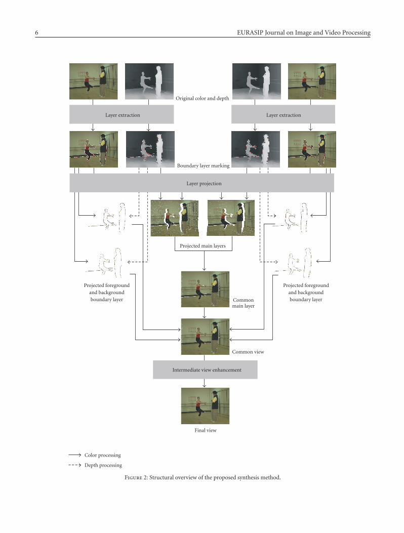
Hence, our view synthesis process consists of three parts:layer extraction (edge detection and separation into reliableand boundary regions), layer projection (separate DIBR ofregions and fusion), and intermediate view enhancement(correction, cleanup, and filtering). An overview of theprocess is shown in Figure 2. Input data for our method areoriginal color and per-pixel depth data. The solid arrowsrepresent color processing, while dashed arrows show depthprocessing or depth data usage for projection or edgedetection purposes. From the depth information, the layersare extracted along the significant depth discontinuities,as described in Section 4.1. In the next stage in Figure 2,all layers from the marked color buffers are projectedinto separate layer buffers for the intermediate view. Theintermediate view is created by merging the two projectedmain layers first. Afterwards, foreground and backgroundboundary layers are added, as described in Section 4.2.Finally, image enhancement, such as hole filling and edgesmoothing, are applied to create the final intermediateview, as shown in Section 4.3. The processing time of thealgorithms depends linearly on the number of pixels in animage. That is, if image resolution is doubled, four times theprocessing time is required.
The idea to work with a layered approached was alreadyinvestigated in [29] for the application of free viewpointnavigation, where a boundary layer of a certain widthalong significant depth discontinuities was extracted. In our
approach, we further improved this idea. Moreover, while theapproach in [29] operates with geometric primitives (trian-gles) for rendering, supported by 3D graphics functions, ourapproach was generically implemented as an image-based 3Dwarping process. Thus, we can actively control the differentinterpolation functions that occur in the view synthesis.
In computer graphics, such projection methods aresometimes implemented as point splat algorithms, whereeach pixel is defined as a 3D sphere with a certain radius,controlled by the point splat function. In such applications,interpolation and small hole filling are carried out automati-cally around each pixel, depending on the applied point splatfunction. Usually, this function is defined globally for animage, such that different requirements on hole filling andinterpolation cannot be addressed. Therefore, we decidedto use classical image-based interpolation algorithms tosolve these problems and to improve the visual quality ofsynthesized views as described in Section 3.
4.1. Layer extraction
In the first part of the rendering approach, we distinguishbetween reliable and unreliable depth regions in the originalviews. The areas along object boundaries are consideredunreliable, since boundary samples usually have mixedforeground/background colors and can create artifacts afterprojection into novel views. Further, errors from depthestimation mainly distort object boundaries. Therefore,similar to [29], significant depth discontinuities are detectedto create main and boundary layers. For this, we use a Cannyedge detector [30] with a content-adaptive significancethreshold (110 in our experiments) operating on the depthimages and mark a 7-sample-wide area as unreliable alongthe detected edges. The significance threshold value wasfound experimentally for the used test sets to give thebest results in finding true depth edges. Since test datawith appropriate depth maps is still very limited, furtherinvestigations on automatic threshold selection can only becarried out in the future, if more test data becomes available.
In contrast to [29], the unreliable area is split into aforeground and background boundary layers, as shown inFigure 3 as black and white areas, respectively, to allowdifferent processing.
4.2. Layer projection
The layer projection extends the general formulationof depth-based intermediate view synthesis, presented inSection 3. This second part of the processing chain is themain block of the view synthesis algorithm. Inputs are aleft and a right original images, associated depth maps,associated camera calibration information, the interpolationparameter λ ∈ [0 · · · 1], all presented in Section 3, andassociated label information as shown in Figure 3. Differentlylabeled regions from both input images are projected to thevirtual view position separately and the results are fusedfollowing depth ordering and reliability criteria.
Following the general approach, presented in Section 3,both main layers are projected into separate color or color
6 EURASIP Journal on Image and Video Processing
Original color and depth
Boundary layer marking
Layer projection
Layer extraction Layer extraction
Projected main layers
Commonmain layer
Common view
Final view
Intermediate view enhancement
Projected foregroundand backgroundboundary layer
Projected foregroundand backgroundboundary layer
Color processing
Depth processing
Figure 2: Structural overview of the proposed synthesis method.

Karsten Muller et al. 7
Figure 3: Layer Assignment along significant depth discontinuities:foreground boundary layer (black), background boundary layer(white), and main layer (grey values).
Figure 4: Common main layer after projection.
buffers l1 and l2, using the corresponding floating-point realdepth data z1 and z2. From this, a common main layer lM,λ iscreated by varying the general interpolation formula (10) asfollows:
lM,λ
=
⎧⎪⎪⎪⎨
⎪⎪⎪⎩
(1− λ)l1 + λl2, if zλ,1, zλ,2 exist,∣∣zλ,1 − zλ,2
∣∣ < ε,
l2, if zλ,1 does not exist or zλ,2 > zλ,1 + ε,
l1, if zλ,2 does not exist or zλ,1 > zλ,2 + ε,(11)
where ε represents a significance value, which was set to 1.0for the experiments and zλ,1 and zλ,2 represent the projecteddepth values with respect to the intermediate view. Theseprojected depth values are used to decide on the depthordering of both color values. The method in (11) guaranteesthat either the front-most sample from each view is used,or both samples are λ-interpolated, if they have similarprojected depth values. The interpolation further reducespossible illumination differences between the original viewsand provides smooth transition when navigating from oneoriginal camera view to the other. A resulting common main
Figure 5: Intermediate view after layer projection.
layer is shown in Figure 4. The interpolation process (11) alsocreates a common floating-point depth buffer zM,λ:
zM,λ = min(zλ,1, zλ,2
). (12)
In the next step, the foreground boundary layers lF,1 and lF,2
are projected and a common layer for color lF,λ and floating-point depth zF,λ is created similar to the main-layer method,described in (12). Then, the common main and foregroundboundary layers are merged as follows:
lFM,λ ={lF,λ, if zF,λ ≤ zM,λ,
lM,λ, if zF,λ > zM,λ.(13)
Here, only a simple depth test is used. The front-most samplefrom either layer is taken, which is mostly the foregroundboundary sample. Besides the new common color layer lFM,λ,the associated depth layer zFM,λ is created similarly to (12).
In the last step of the projection process, the backgroundboundary layers lB,1 and lB,2 are projected to lB,λ and mergedwith lFM,λ:
lλ ={lFM,λ, if zFM,λ exists,
lB,λ, if zFM,λ does not exist(14)
to create the final color or color lλ and depth zλ similarto (12). The background layer information lB,λ is only usedto fill empty regions in the intermediate view. Since thecommon main layer lFM,λ already covers most of the samplesaround foreground objects, as can be seen in Figure 4,only few background boundary samples are used and thusthe color-distorted samples at object boundaries from theoriginal views are omitted. Those are known to createcorona-like artifacts within background regions using simple3D warping algorithms, which is avoided by our layeredapproach with 2 different kinds of boundary layers. Theresult after layer projection is shown in Figure 5.
4.3. Intermediate view enhancement
The last part of our algorithm provides postprocessingafter layer projection and includes correction, cleanup, and

8 EURASIP Journal on Image and Video Processing
filtering processes. Two types of holes may still occur inthe rendered images at this stage: small cracks and largermissing areas. The first type of holes is small cracks whichcan occur in the entire image area and are introduced bythe forward mapping nature of image-based 3D warping.Each point from an original image is projected separatelyinto the intermediate view, and falls in general onto afloating point coordinate. This position is quantized tothe nearest neighbor position of the integer sample raster.Unfortunately, quantization may leave some samples unfilledbeing visible as thin black lines in Figures 4 and 5. Insome cases, such cracks in foreground regions are filledby background information from the other original image.This results in artifacts as shown in Figure 6, left, wherebackground samples shine through the foreground object.
Such artifacts are detected by finding depth values thatare significantly larger than both neighboring values inhorizontal, vertical, or diagonal directions:
ghor = 2·zλ(uλ, vλ
)− zλ(uλ − 1, vλ
)− zλ(uλ + 1, vλ
),
gver = 2·zλ(uλ, vλ
)− zλ(uλ, vλ − 1
)− zλ(uλ, vλ + 1
),
gdiag,1 = 2·zλ(uλ, vλ
)− zλ(uλ − 1, vλ − 1
)−zλ(uλ+1, vλ + 1
),
gdiag,2 = 2·zλ(uλ, vλ
)− zλ(uλ + 1, vλ − 1
)−zλ(uλ−1, vλ + 1
).
(15)
This refers to background pixels within a foreground region.From the directional significance values, the maximum valuegmax is calculated as follows:
gmax = max(ghor, gver, gdiag,1, gdiag,2
). (16)
If gmax exceeds a specific threshold (40 in our experiments),the color value lλ(uλ, vλ) is substituted by the median valueof neighboring color values assuming that they have correctdepth values assigned. The correction of such an artifact isalso shown in Figure 6, left. Again, the specific threshold wasdetermined experimentally and future investigations have tobe carried out if new test data becomes available.
The second type of holes includes larger missing areas.They either occur due to erroneous depth values, or areareas that become visible in the intermediate view, whilebeing occluded in both original views. Such larger holesare currently filled linewise with neighboring available back-ground information, as shown in Figure 6, middle. Here, thetwo corresponding depth values at the two-hole boundarypixel are analyzed to find background color samples toextrapolate into the hole region. This simple constant-colorextrapolation of the background pixel leads to better results,than an unconstrained linear interpolation between bothvalues. Often, one of the hole boundary pixels belongs tothe foreground object and its color value would lead tocolor bleeding into the hole. This approach leads to goodfilling results for missing areas due to depth errors. In casesof fillings for disocclusions, sometimes both hole boundarypixels are foreground pixels and the foreground color isincorrectly extrapolated into the background hole.
Here, one of the fundamental problems of view inter-polation from sparse views occurs, which are disocclusionsin intermediate views, where no original information is
available in any view. For this, no general solution exists. Insome cases, hole filling algorithms could be extended into thetemporal dimension to hope for additional data in previousor future frames, if a foreground object has moved enoughto reveal required background information. However, sincethe degree of motion cannot be predicted, this approachhas limitations and was not considered for our implementedmethod.
Finally, foreground objects are low-pass filtered along theedges to provide a natural appearance, as shown in Figure 6,right. In the original views, object boundary samples area color mixture of foreground-background due to initialsampling and filtering during image capturing. In therendered intermediate views of our layered approach, thesemixed color samples are often excluded in order to avoidcorona artifacts in background areas. Consequently, someforeground-background boundaries look unnaturally sharp,as if foreground objects were artificially inserted into thescene. Therefore, the above-mentioned Canny edge detectionfilter [30] is applied to the final depth information zλ of theintermediate view to detect edges with depth gradients |∇zλ|above the Canny significance threshold η (η = 50 in ourexperiments). Then, the color buffer is convolved with anaveraging three-tap low-pass filter in both spatial directionsat corresponding significant depth edges to provide a morenatural appearance:
lλ,Final =
⎧⎪⎪⎪⎪⎪⎨
⎪⎪⎪⎪⎪⎩
lλ∗19
⎛
⎜⎜⎝
1 1 1
1 1 1
1 1 1
⎞
⎟⎟⎠ , if
∣∣∇zλ
∣∣ ≥ η,
lλ, if∣∣∇zλ
∣∣ < η.
(17)
Additionally, the filtering helps to reduce remaining artifactsalong depth discontinuities.
5. VIEW SYNTHESIS EXAMPLES
A resulting intermediate view after all processing steps isshown in Figure 7.
Here, the middle view between two original cameras wassynthesized, that is, λ = 0.5, which corresponds to a physicaldistance of 1 cm to both original cameras in this case. Thevirtual view is of excellent quality without visible artifacts.
Details of rendered views are shown in Figure 8. Thetop row shows examples of standard 3D warping withoutthe specific layer projection steps introduced in Section 4.Corona artifacts occur at foreground/background bound-aries. Some dark foreground pixels are mistakenly addedto lighter background areas, resulting in typical corona-type additional contours around objects. Such artifacts canchange over time, resulting in very annoying effects withinthe rendered video. This can make the whole concept of3DV unacceptable. The bottom row in Figure 8 shows thecorresponding rendering details using our improvements tothe 3D warping process as introduced in Section 4. Coronaartifacts are widely removed. With minimum artifacts ofindividual images, also the video quality is significantlyincreased, thus our views synthesis algorithm is capable of

Karsten Muller et al. 9
Figure 6: Artifacts (top) and artifact removal (bottom). Crack sample removal (left), area filling (middle), and edge smoothing (right).
Figure 7: Final intermediate view synthesis after filtering.
forming the basis for the advanced 3DV concept based onMVD.
Further comparisons, for example, with the method from[29] are only limited, since for this method, no results for theBallet sequence are available. For the Breakdancers sequence,the interpolation quality seems to be equal, although dif-ferent algorithms were applied. In our approach, we useda fixed boundary layer width, while in [29], complex alphamatting is used to deal with semitransparent areas. Alsono hole filling was applied in [29], such that a comparisonis difficult. Future test data with complex depth structurewill show whether one method has advantages over theother. Currently, we achieve very good visual results with oursynthesis method.
The purpose of the view interpolator is to create N inputviews for a 3DV system out of M views plus depth of an MVDrepresentation. One example is the Philips auto-stereoscopicdisplay, where 9 views with eye-distance (approx. 5 cm) arerequired as input. For such a setup, as illustrated in Figure 1,
five of the resulting nine views are shown in Figure 9 forthe Ballet and Breakdancers datasets. The camera spacingof these datasets is 20 cm. Three intermediate views withλ = {1/4, 1/2, 3/4} have been created between two originalcameras. The leftmost and rightmost images in Figure 9are original views. The three images inbetween are virtualviews not exhibiting any artifacts. Pairwise stereoscopic viewsare available to support motion parallax and 3D depthimpression.
6. CONCLUSIONS
An advanced system for 3DV based on MVD is presentedin this paper. It efficiently supports auto and multiviewstereoscopic displays. This latter type of 3D displays enablesmultiuser 3DV sensation in a living room environmentwithout the necessity to wear glasses, but with motionparallax impression and full social interaction. MVD canserve as a generic format for 3DV in this concept as it hasclear advantages over alternative concepts based on MVCor MPEG-C Part 3 in terms of data rate, quality, andfunctionality. This concept, however, integrates a numberof sophisticated processing steps that partially still requireresearch. Among those, high-quality intermediate view syn-thesis is crucial to make this concept feasible. It is knownthat such algorithms may introduce annoying artifacts alongdepth discontinuities. Therefore, the approach presentedhere separates input images in reliable and unreliable areasbased on edge detection in high-quality depth images, sincethese edges correspond to depth discontinuities. Reliableand unreliable image areas are treated separately and theresults are merged depending on reliability criteria. Specificpostprocessing algorithms are introduced to further enhancerendered view quality. This includes different hole-fillingapproaches as well as a final smoothing filter along depthdiscontinuities in the rendered views to reduce remaining

10 EURASIP Journal on Image and Video Processing
Figure 8: Details in the intermediate view for simple merging and our proposed method.
Figure 9: Five views in stereo pair distance for 9-view auto-stereoscopic display. Two views at original camera positions (far left and farright) and intermediate views for Ballet (top) and Breakdancers dataset(s) (bottom).
artifacts. A position-dependent blending factor is usedto weight contributions from different input images. Thepresented results show that the processing in layers tak-ing reliability information along depth discontinuities intoaccount significantly reduces rendering artifacts. Coronaartifacts that frequently occur with standard 3D warpingare widely eliminated. High-quality intermediate views aregenerated with the presented algorithm. With this, animportant building block within the advanced 3DV con-cept for MVD is shown to be available. Besides furtheroptimization, our future work will include development ofall other building blocks such as acquisition, depth estima-tion, coding, and transmission as well as the final systemintegration.
ACKNOWLEDGMENT
The authors would like to thank the Interactive Visual MediaGroup of Microsoft Research for providing the Ballet andBreakdancers datasets.
REFERENCES
[1] A. Smolic, K. Mueller, P. Merkle, et al., “3D video andfree viewpoint video—technologies, applications and MPEGstandards,” in Proceedings of the IEEE International Conferenceon Multimedia and Expo (ICME ’06), pp. 2161–2164, Toronto,Canada, July 2006.
[2] J. Konrad and M. Halle, “3-D displays and signal processing:an answer to 3-D ills?” IEEE Signal Processing Magazine, vol.24, no. 6, pp. 97–111, 2007.
[3] P. Kauff, N. Atzpadin, C. Fehn, et al., “Depth map creationand image-based rendering for advanced 3DTV servicesproviding interoperability and scalability,” Signal Processing:Image Communication, vol. 22, no. 2, pp. 217–234, 2007.
[4] October 2008, http://www.philips.com/3Dsolutions.[5] P. Merkle, A. Smolic, K. Muller, and T. Wiegand, “Efficient
prediction structures for multiview video coding,” IEEETransactions on Circuits and Systems for Video Technology, vol.17, no. 11, pp. 1461–1473, 2007.
[6] C. Fehn, P. Kauff, M. Op de Beeck, et al., “An evolutionaryand optimised approach on 3D-TV,” in Proceedings of theInternational Broadcast Convention (IBC ’02), pp. 357–365,Amsterdam, The Netherlands, September 2002.

Karsten Muller et al. 11
[7] ISO/IEC JTC1/SC29/WG11, “Text of ISO/IEC FDIS 23002-3Representation of Auxiliary Video and Supplemental Informa-tion,” Doc. N8768, Marrakech, Morocco, January 2007.
[8] ISO/IEC JTC1/SC29/WG11, “Text of ISO/IEC 13818-1:2003/FDAM2 Carriage of Auxiliary Data,” Doc. N8799,Marrakech, Morocco, January 2007.
[9] F. Forster, M. Lang, and B. Radig, “Real-time range imagingfor dynamic scenes using colour-edge based structured light,”in Proceedings of the 16th International Conference on PatternRecognition (ICPR ’02), vol. 3, pp. 645–648, Quebec, Canada,August 2002.
[10] J. Salvi, J. Pages, and J. Battle, “Patter codification strategies instructured light systems,” Pattern Recognition, vol. 37, no. 4,pp. 827–849, 2004.
[11] R. Koch, M. Pollefeys, and L. Van Gool, “Multi viewpointstereo from uncalibrated video sequences,” in Proceedings ofthe 5th European Conference on Computer Vision (ECCV ’98),vol. 1406 of Lecture Notes in Computer Science, p. 55, Springer,Freiburg, Germany, June 1998.
[12] Y. Li, C.-K. Tang, and H.-Y. Shum, “Efficient dense depthestimation from dense multiperspective panoramas,” in Pro-ceedings of the 8th International Conference on Computer Vision(ICCV ’01), vol. 1, pp. 119–126, Vancouver, Canada, July 2001.
[13] C. Strecha, T. Tuytelaars, and L. Van Gool, “Dense matchingof multiple wide-baseline views,” in Proceedings of the 9th IEEEInternational Conference on Computer Vision (ICCV ’03), vol.2, pp. 1194–1201, Nice, France, October 2003.
[14] J. Woetzel and R. Koch, “Real-time multi-stereo depth esti-mation on GPU with approximative discontinuity handling,”in Proceedings of the 1st European Conference on Visual MediaProduction (CVMP ’04), pp. 245–254, London, UK, March2004.
[15] R. Y. Tsai, “A versatile camera calibration technique for high-accuracy 3D machine vision metrology using off-the-shelf TVcameras and lenses,” IEEE Journal of Robotics and Automation,vol. 3, no. 4, pp. 323–344, 1987.
[16] O. Faugeras, Three-Dimensional Computer Vision: A GeometricViewpoint, MIT Press, Cambridge, Mass, USA, 1993.
[17] R. Hartley and A. Zisserman, Multiple View Geometry inComputer Vision, Cambridge University Press, Cambridge,UK, 2003.
[18] K. Shoemake, “Animating rotation with quaternion curves,”ACM SIGGRAPH Computer Graphics, vol. 19, no. 3, pp. 245–254, 1985.
[19] S. Avidan and A. Shashua, “Novel view synthesis in tensorspace,” in Proceedings of the IEEE Computer Society Conferenceon Computer Vision and Pattern Recognition (CVPR ’97), pp.1034–1040, San Juan, Puerto Rico, USA, June 1997.
[20] S. E. Chen and L. Williams, “View interpolation for image syn-thesis,” in Proceedings of the 20th Annual Conference on Com-puter Graphics and Interactive Techniques (SIGGRAPH ’93),pp. 279–288, Anaheim, Calif, USA, August 1993.
[21] J. S. McVeigh, M. W. Siegel, and A. G. Jordan, “Intermediateview synthesis considering occluded and ambiguously refer-enced image regions,” Signal Processing: Image Communica-tion, vol. 9, no. 1, pp. 21–28, 1996.
[22] D. Scharstein, “Stereo vision for view synthesis,” in Proceedingsof the IEEE Computer Society Conference on Computer Visionand Pattern Recognition (CVPR ’96), pp. 852–858, San Fran-cisco, Calif, USA, June 1996.
[23] G.-C. Chang and W.-N. Lie, “Multi-view image compressionand intermediate view synthesis for stereoscopic applications,”
in Proceedings of the IEEE International Symposium on Circuitsand Systems (ISCAS ’00), vol. 2, pp. 277–280, Geneva, Switzer-land, May 2000.
[24] ISO/IEC JTC1/SC29/WG11, “Description of ExplorationExperiments in 3D Video,” Doc. N9596, Antalya, Turkey,January 2008.
[25] A. Katayama, K. Tanaka, T. Oshino, and H. Tamura, “View-point dependent stereoscopic display using interpolation ofmulti-viewpoint images,” in Stereoscopic Displays and VirtualReality Systems II, S. Fisher, J. Merritt, and B. Bolas, Eds., vol.2409 of Proceedings of SPIE, pp. 11–20, San Jose, Calif, USA,February 1995.
[26] M. Morimoto and K. Fujii, “A view synthesis method basedon object coding and simple disparity model,” in Proceedingsof the IEEE International Symposium on Communications andInformation Technologies (ISCIT ’04), vol. 2, pp. 853–856,Sapporo, Japan, October 2004.
[27] J. D. Oh, S. Ma, and C.-C. J. Kuo, “Disparity estimation andvirtual view synthesis from stereo video,” in Proceedings ofthe IEEE International Symposium on Circuits and Systems(ISCAS ’07), pp. 993–996, New Orleans, La, USA, May 2007.
[28] N. L. Chang and A. Zakhor, “A multivalued representation forview synthesis,” in Proceedings of the International Conferenceon Image Processing (ICIP ’99), vol. 2, pp. 505–509, Kobe,Japan, October 1999.
[29] C. L. Zitnick, S. B. Kang, M. Uyttendaele, S. Winder, andR. Szeliski, “High-quality video view interpolation using alayered representation,” ACM Transactions on Graphics, vol.23, no. 3, pp. 600–608, 2004.
[30] J. Canny, “A computational approach to edge detection,” IEEETransactions on Pattern Analysis and Machine Intelligence, vol.8, no. 6, pp. 679–698, 1986.