view the full guide
TRANSCRIPT

Public Water Supply Management
An Introductory Guide
Author: David Woods
An FWR Guide
FR/G0009
October 2011
© Foundation for Water Research
Price: £15.00
(20% discount for FWR Members)
Foundation for Water Research Allen House, The Listons
Liston Road, Marlow, Bucks. SL7 1FD, U.K.
Tel: +44 (0) 1628 891589 Fax: +44 (0) 1628 472711 E-mail: [email protected] Home page: www fwr org

Copyright Apart from any fair dealing for the purposes of research or private study, or criticism or review, as permitted under the UK Copyright, Designs and Patents Act (1998), no part of this publication may be reproduced, stored or transmitted in any form or by any means, without the prior permission in writing of FWR. Disclaimer Whilst every effort has been made to ensure accuracy FWR will not accept responsibility for any loss or damage suffered by any person acting or refraining from acting upon any material contained in this publication. Appropriate professional advice should be sought when making important decisions to ensure the information is correct, up-to-date and applicable to specific circumstances.

Public Water Supply Management
An Introductory Guide
Author: David Woods Acknowledgement: The author is grateful to Mike Waite for his helpful input to the production of this Guide. Cover Page Image: Farmoor Reservoir © Thames Water Utilities Ltd.


Contents
1.0 Preface
1 2.0 Introduction and the Water Cycle 2 3.0 Water Demand: how much water is needed? 4 4.0 Water Resources 4
4.1 Surface Water Sources 5 4.2 Lakes (natural and manmade) 5 4.3 Rivers 6 4.4 Groundwater 7 5.0 Natural Water Quality 9
5.1 Groundwater Quality 10 5.2 Water Hardness 10 5.3 Surface Water Quality 11 6.0 Drinking Water Quality Standards 11 7.0 The Extent and Stages of Treatment for Each
Water Type
13
7.1 Groundwater 137.2 Upland Reservoir Water 147.3 Lowland River Water 167.4 Advanced Water Treatment 16
8.0 Unit Processes in Water Treatment 17
8.1 Clarification 178.2 Filtration 208.3 Disinfection 228.4 Chlorination 24
9.0 Water Distribution 26
9.1 Service Reservoirs 27 9.2 Mains and Services 28 9.3 Leakage Control 29 9.4 Levels of Service and Water Quality Issues 30

10.0 Reflections 31 11.0 Glossary of Terms 31 12.0 Further Information Sources 34

1
1.0 Preface The purpose of this Guide is to provide an introduction to public water supply management for those with limited technical background. It gives information to support readers interested in public water supply matters. The objective of public water supply management is to supply wholesome water within set quality and levels of service criteria in sufficient quantity to meet consumer demand. Chemical and microbiological quality is rigorously monitored by water suppliers and, where necessary, action is taken immediately to rectify any deficiencies. The link between contaminated water supplies and disease was demonstrated in the early 19thC. By the end of the 19thC the drive to provide safe water supplies and sanitation dramatically improved public health in the urban environment. Prior to this epidemics of waterborne diseases such as cholera and typhoid were common. Although chlorine was first used on a large scale in 1908 in Jersey City, USA, it was not until an outbreak of typhoid in Croydon in 1937 that routine disinfection of water supplies in England became established practice. In more recent times there have been isolated cases of intestinal disease associated with public water supplies, but these have been localised and mainly associated with isolated instances of inadequate treatment or operational difficulties. This Guide will explore the various sources of water for supply indicating the water quality issues associated with each; outline the quality standards that must be achieved and maintained in public water supplies; describe the most commonly used treatment processes and the arrangements for distributing water to homes and places of work. In compiling this Guide the author acknowledges that he has made free use of information from a wide range of sources.

2
2.0 Introduction and the Water Cycle Water supply management is a man-made component of the water cycle (Figure 1) and itself forms part of the water services cycle (Figure 2). Water is taken from lakes, rivers and underground strata and is treated and distributed for use by man. Water companies take great care to ensure that the water supplied to customers is wholesome and complies with national and EU standards for drinking water quality. It is this journey from water source through treatment and distribution to customers that is outlined in this Guide. Detailed consideration of EU and UK law governing water supply management is outside the scope of this Guide: however, the quality standards and duties that arise are outlined. A list of FWR Guides and ROCKs is appended to provide wider reading on water supply issues.
Figure 1: The Water Cycle © Drinking Water Inspectorate
As Figure 2 shows, the public water supply system comprises four components: the water source, the water treatment processes, and water distribution to meet customer demand.

3
Water supply is part of the water services cycle which is itself a component of the water cycle.
Figure 2: The Water Services Cycle
WATER SOURCES
WATER TREATMENT
DISTRIBUTION
SEWERAGE AND SEWAGE
TREATMENT
Rivers, lakes and reservoirs, groundwater
WATER DEMAND
RIVER
Extent needed depends on the source used
System of trunk mains, service reservoirs and local mains
Homes, industry, commerce and losses through leakage
Sewers convey sewage to works for treatment to meet river quality needs
Rivers used for recreation, species conservation and as a water source
4
3.0 Water Demand: how much water is needed? The consumption of water may be divided into the following general categories.
• Domestic – household purposes (including car washing and garden watering) • Trade - industries, factories, businesses, shops, offices, hotels, institutions,
etc. • Agriculture – Farms, livestock, irrigation, dairies, greenhouses, etc. • Public – fire-fighting, swimming pools, street watering, fountains, parks, etc. • Losses – leakage from mains, connections, service pipes, service reservoirs,
water used for flushing mains, etc. Water use in the UK has been rising at 1% per annum since 1930 with each person using about 150 litres of water each day. For example, a running tap uses 6 litres per minute, a shower uses 9-14 litres per minute and a hosepipe uses 1000 litres per hour. The demand for water shows diurnal variation with night-time demand usually being significantly lower than that in the day. Such variations may be smoothed out if large industrial water users are present in the water distribution system. Water demand may show significant seasonal variation. For example, extensive garden watering in dry summers or, conversely, excessive leakage from frozen water mains and service pipes during severe winter weather. Water supply systems must be designed to cope with these variations in demand without any deterioration to the quality of the water supplied. 4.0 Water Resources The term water resources is used for the total freshwater available for use by man. Surprisingly, the UK has less available freshwater per head of population than many other countries in Europe. On average, the South East has less water available per person than the Sudan and Syria and London is drier than Istanbul. Water resources, (sources of freshwater), must therefore be carefully husbanded and water use managed effectively. There are two principal types of water resource: surface water and groundwater. In some parts of the world, where freshwater resources are limited, desalination of sea-water is extensively practiced. This is very rare in the UK, although a desalination plant operates at times of peak demand in the London area. An excellent account of world water resources is given in White W.R, World Water: Resources, Usage and the Role of Man-Made Reservoirs, Review of Current Knowledge, published by the Foundation for Water Research. In this Guide the term water sources is used for water resources that are abstracted for public water supply purposes.
5
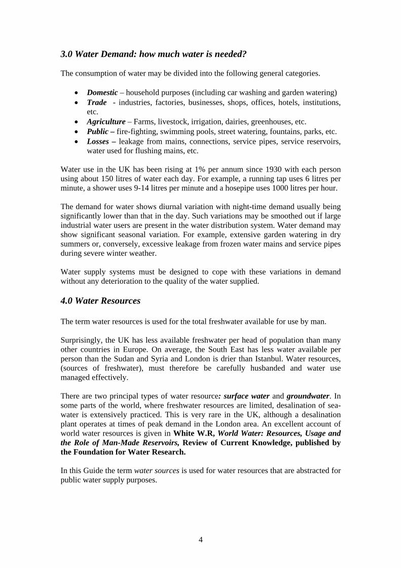
4.1 Surface Water Sources Surface water is water in lakes, reservoirs, rivers or freshwater wetlands. It is replenished by rainfall and naturally lost by drainage to oceans, evaporation and seepage into the underground strata.
Figure 3: Clywedog reservoir – Mid-Wales
4.2 Lakes (natural and man made) The capacity of natural lakes may be enhanced by building a dam to increase the water storage capacity. The natural water catchment of such reservoirs is sufficient to ensure reliable supplies in all but the most extreme weather conditions. The water stored may be abstracted directly, or it can be used to augment river flows and so enable year round abstraction downstream. This latter arrangement avoids the necessity to provide an expensive aqueduct to the treatment works that may be many miles away. The Derwent Valley reservoirs in North Derbyshire (UK) are dual function providing direct supplies by aqueduct to Sheffield and to the Midlands. They are also used to regulate the flow of the river Derwent to support abstraction downstream. The Elan Valley reservoirs in Mid Wales supply water directly to treatment works in Birmingham (UK) via an aqueduct. Artificial lakes, such as Carsington Water in Derbyshire (UK), are created by damming a suitable valley and pumping river water to it during times of the year

6
when river flows are high. When river levels are low water is released back to the river to protect flora and fauna and to allow abstraction to continue downstream. In all cases the reservoirs must be operated such that a minimum flow, prescribed by the Environment Agency, is maintained in the downstream watercourse under all but the severest drought conditions. Water from reservoir and river sources has to be treated before use for public water supply, the extent of treatment being influenced by the nature of the reservoir catchment. 4.3 Rivers Water abstraction for public water supply from lowland rivers is common in the UK. However, not all rivers are suitable for such abstraction.
Figure 4: River Thames is used as a source for water supply
For example, until recently the River Trent, in the UK Midlands, was considered to be too polluted for such use. Pollution from Birmingham and the Black Country entered the River Tame, a tributary of the Trent, which was already polluted by passage through the Stoke area. In recent times the river system has been extensively cleaned up such that abstraction for water supply may be possible with advanced treatment and blending before use. On the other hand the UK Midlands River Severn, a significantly cleaner river, is extensively abstracted for public water supply. Frequently, river water is first abstracted to a bank-side storage reservoir located beside the river and adjacent to the water treatment plant. Much of London’s water supply comes via such reservoirs. This provides strategic water storage in times of

7
low river flow. It also acts as a buffer to deal with changes to water demand, to even out variations in river water quality and to allow the treatment plant to continue to operate when river abstraction has to cease due to, for example, contamination caused by an accident upstream. Water abstracted from lowland rivers normally requires extensive treatment before it can be used for public water supply. 4.4 Groundwater Groundwater is an important water resource in the UK, comprising about a third of the water used for public water supply. Groundwater is water that has fallen as rainfall, trickled downwards through soil and permeable rock strata to accumulate in underground fissures in the rock strata. This natural process of percolation often results in high quality groundwater that requires little or no treatment other than disinfection before being put into public water supply. Inevitably, the chemical composition of groundwater will depend on the nature of the rock strata. For example, water from limestone strata will exhibit greater ‘hardness’ than that from the Bunter sandstone, see 5.2 below. An aquifer comprises fissured, permeable rock that stores groundwater and allows it to flow readily into a well or borehole. Aquifers may be very extensive, as with the Bunter sandstone aquifer in Staffordshire (UK) or relatively small in situations where small zones of permeable rock are surrounded by impermeable strata. The water in an aquifer has a natural top level just as in a lake and that level is referred to as the water table. Aquifers may be confined or unconfined as illustrated in Figure 5. The water in a confined aquifer may enter the aquifer through permeable strata some distance from the well or borehole. Note that Figure 5 shows two wells one of which is artesian. Artesian wells are found where water is held under pressure in a confined aquifer. Once the well or borehole penetrates the impermeable layer the pressure forces water from the aquifer to the surface. Groundwater must be protected from contamination by accidental pollution, such as chemical spills, and from continual low level contamination, such as by nitrates from agricultural fertilizers. Where nitrate pollution is a problem there are provisions for the designation of Nitrate Vulnerable Zones under the Nitrate Pollution Prevention Regulations 2008 arising from the EC Nitrate Directive. Within these Zones farmers must comply with the requirements to qualify for farming subsidies. Groundwater is abstracted by sinking wells or boreholes into the rock strata. Adits, or side tunnels, are often incorporated into wells to increase the water collection zone.

8
Figure 5: Groundwater abstraction from unconfined and confined aquifers
© East Orange Water Commission
Figure 6: Tancred Pit Borehole – discharging after heavy rain © Environment Agency
Footnote: It is unusual for boreholes to discharge in this way. At Tancred Pit the water table is normally high and the photograph was taken after prolonged heavy rain. Boreholes can be drilled several hundred feet into the strata. A submersible pump is lowered into the borehole and when this is operating water will be drawn from a large area around the borehole itself. The water table is lowered in this zone which results in what is termed a cone of depression (see Figure 7 below) and water is drawn in from further afield. Where the aquifer lies close to the coast care has to be taken to ensure that sea water is not drawn into the bore; this is known as saline intrusion.

9
When the aquifer is unconfined there is a danger that surface pollution may be drawn down within the cone of depression resulting in contamination of the source. It is therefore important to protect the area surrounding the borehole installation. An excellent account of all aspects of groundwater is found in Downing, R.A Groundwater: our hidden asset, , an Earthwise publication.
Figure 7: Cone of depression
5.0 Natural Water Quality Water quality characteristics fall into five broad categories:-
1. Organoleptic. Characteristics that are detected by the normal senses of sight, taste and touch.
2. Physicochemical. Parameters such as electrical conductivity (a measure of the total mineral constituents), temperature and pH (a measure of the acidity or alkalinity of the water). The category also includes chloride, sulphate, calcium and magnesium.
3. Toxic substances. Includes arsenic, cadmium, cyanide, chromium, lead and many others recognised as toxic at low concentrations.
4. Substances undesirable in excess. Includes nitrates, total organic carbon, iron and manganese, some of which can be toxic at high concentrations.

10
5. Microbiological. Water supplies are not sterile and may contain a wide range of harmless bacteria. When water treatment fails, or water in distribution is subsequently contaminated, it may contain any of a variety of harmful bacteria, viruses or protozoa. A group of organisms known as E.coli, which are of faecal origin (from the intestines) and generally harmless are used as indicators that pathogenic (disease producing) bacteria may be present. These, along with some other types of bacteria, are collectively referred to as indicator bacteria.
The concentrations of most chemical impurities in water are expressed either as milligrams or micrograms per litre. As expected the chemical and biological composition of raw, untreated, waters will vary depending on the catchment and the underground strata. For example, upland reservoirs in peaty catchments overlying impermeable Millstone Grit strata will be coloured, contain suspended peat solids, be weakly acidic and low in hardness and alkalinity. Whereas waters from boreholes sunk in limestone strata will be hard and alkaline. (See note on water hardness below). 5.1 Groundwater Quality Groundwater quality is related to the strata holding the aquifer as is illustrated in figure 8 below, but may also be heavily influenced by the nature and use of the overlying land.
Essex Kent Notts Lincs Northumberland Chalk Greensand Sandstone Limestone Permian Calcium 144 14 22 142 93 Magnesium 21 3 22 8 51 Sodium 41 95 12 26 22 Potassium 8 4 -- -- 4 Carbonate 147 123 66 141 167 Sulphate 211 13 16 135 136 Chloride 51 27 18 32 49 Nitrate 20 Nil 1 9 19 Fluoride 0.04 0.2 0.05 0.04 0.4 Silica 17 9 5 5 7 Iron 0.8 Nil 0.03 Nil 0.05 Manganese Nil Nil -- -- Nil Phosphate --- -- -- -- Nil Total dissolved solids
665 280 170 505 540
CO3hardness 245 50 110 235 280 Non CO3 hardness
200 Nil 36 153 164
Figure 8: Examples of typical analyses of ground waters from different aquifers in the UK (mg/l)
5.2 Water Hardness Water hardness is related to the property of a given volume of water to produce lather with a given quantity of soap: soft waters readily produce lather whilst hard waters produce little lather. There are two types of water hardness: temporary and permanent. In practically all cases the hardness of water depends on the presence of

11
calcium and magnesium bicarbonates and sulphates: temporary hardness being due to the bicarbonates and permanent hardness being due to the sulphates. Bicarbonates in solution decompose on heating. For example, calcium bicarbonate breaks down to give calcium carbonate, carbon dioxide and water. The calcium carbonate precipitates from solution and is responsible for the ‘furring up’ of kettles, hot water pipe-work, etc., often found in hard water areas.
Ca(HCO3)2 CaCO3 + CO2 + H2O 5.3 Surface Water Quality Surface water quality is also related to the geology of the catchment, but is also highly dependant on the local flora and land use. River water quality will depend heavily upon the agricultural, industrial and urban nature of the river catchment. High quality surface waters, such as that abstracted from Loch Katrine for supply to Glasgow (Scotland) have been thought to require little treatment other than disinfection before entering distribution. However, since the recognition of the protozoan parasite Cryptosporidium as a waterborne pathogen which is resistant to conventional disinfection, and a number of cryptosporidiosis outbreaks, including one related to supply from Loch Katrine, such sources are now being given full conventional treatment where there is any risk of the organism being present. Lowland river water invariably requires significant treatment, and occasionally advanced treatment, before it meets the quality standards for public water supply. The responsibility for protecting surface and groundwater quality rests with the Environment Agency in England and Wales, the Scottish Environmental Protection Agency in Scotland and the Northern Ireland Environment Agency in Northern Ireland. They are also responsible for licensing water abstraction. Public water supply and environmental protection are major features of the River Basin Management Plans developed by these agencies to comply with the EU Water Framework Directive. 6.0 Drinking Water Quality Standards A full account of the development of standards and the current standards and guidelines is beyond the scope of this guide but can be found in John Fawell, MBE Drinking Water Standards and Guidelines, an FWR Guide. These standards apply at the consumer’s tap. In England and Wales the Drinking Water Inspectorate (DWI) is responsible for providing independent assurance that water supplied by the water companies meets the required quality standards and is acceptable to consumers. Standards for drinking water quality in the UK are those prescribed by the Water Supply (Water Quality) Regulations 2000 and 2010 which give effect to the Directive 98/83/EC On the quality of water for human consumption. The Directive applies to all water supplied for the purposes of drinking, washing, cooking and the production of food and prescribes standards for four classes of

12
parameters: organoleptic; microbiological; physico-chemical; and toxic substances. See figures 9, 10 and 11 below. It also sets minimum requirements for the frequency of sampling and analysis. Performance against the standards in the Regulations is monitored through audit by the Drinking Water Inspectorate (DWI). DWI published Guidance on the Water Supply (Water Quality) Regulations 2000 (England) in 2010 which replaced earlier guidance on previous Regulations. These Guidelines were not mandatory to water undertakers, but failure to follow them could be taken as failure to exercise due diligence in the event of legal proceedings. The water undertaker has the day to day responsibility for the quality of drinking water supplied to its customers and the sampling and analysis in accordance with Regulations, while DWI monitors and initiates any necessary steps to ensure water undertakers (companies) comply with their statutory duties in respect of drinking water quality. The Water Supply (Water Quality) Regulations were amended in 2010 and a Guidance Document is in preparation.
Colour Turbidity Odour Taste
Figure 9: Organoleptic parameters
Figure 10: Microbiological parameters
Figure 11: Physicochemical and toxic substances
Coliform bacteria
E. coli Enterococci
Clostridium perfringens (Including spores)
Colony counts
Residual disinfectant
Arsenic 1,2 dichloroethane Tetrachloroethane
Aluminium Benzene Fluoride Tetrachloromethanes (THMs)
Ammonium Benzo(a)pyrene Lead Chloride Conductivity Boron Mercury Sulphate Hydrogen ion (pH) Bromate Nickel Total organic carbon
(TOC) Iron Cadmium Pesticides and
related products Tritrium
Manganese Chromium Polycyclic aromatic hydrocarbons (PAH)
Radioactivity – gross alpha
Nitrate Copper Selenium Radioactivity - gross beta
Nitrite Cyanide Sodium Antimony Trichloroethane

13
Figure 12 below compares the type of water quality one might encounter from the analysis of a groundwater, water from an upland reservoir and from a lowland river. The EC Directive standard is shown on the right. All concentrations are in mg/l except for coliforms (the bacteriological parameter) that is given as probable number/ 100ml.
Figure 12: Water qualities typical of the three source types: groundwater,
upland reservoir and lowland river. The EC Standard is that which should not be exceeded in the water after treatment. 7.0 The Extent and Stages of Treatment for Each Water Type Figure 13 (page 15) illustrates the extent and stages of treatment for each of the principal water source types: groundwater, upland reservoir water and lowland river water. Water treatment will first be described in broad terms for each raw water type and the detail of the unit processes will be described later. 7.1 Groundwater We have already seen that good quality ground-waters do not require treatment other than disinfection to eliminate bacteriological contamination. The normal disinfection agent employed is chlorine which has a powerful disinfection action. The level of treatment is such that the treated water entering distribution has a low residual chlorine concentration. This provides some protection against bacterial contamination of the water in distribution and a fall in chlorine concentration may give early warning of such problems. Occasionally, groundwater high in iron and/or manganese may be encountered. This is undesirable since the water may be coloured at the consumer’s tap and there may be staining when clothes are washed. Both iron and manganese concentrations may be
Parameter Groundwater Upland Catchment
Lowland River EC Standard (Maximum)
pH Colour (Hazen) Turbidity(FTU) Ammonia (N) Nitrate (NO3) Hardness(CaCO3) Elec.Cond. Iron (Fe) Manganese (Mn) Coliforms
7.8
<5
0.2
0.01
30
300
700
0.05
0.01
2
4.9
60
8.0
0.2
5.0
30
92
0.6
0.2
500
7.7
80
30
0.6
20
250
550
0.2
0.15
20,000
>6.5 < 9.5
20
4
0.5
50 - -
0.2
0.05
0

14
reduced to acceptable levels by aeration, or chemical oxidation, followed by sand filtration to remove the insoluble iron and manganese compounds formed. Groundwater can also contain high levels of carbon dioxide which are undesirable and aeration can significantly reduce these levels. Where other contaminants, such as nitrate, are present at unacceptable levels, the problem can be overcome by blending with water from a less contaminated or contaminant-free source to produce final water into distribution that meets the quality standard. Other processes such as biological and physico-chemical methods have also been used to reduce nitrate concentrations, but these are outside the scope of this Guide. 7.2 Upland Reservoir Water Waters from upland reservoirs require more extensive treatment than groundwater before they can be put into supply. This may involve preliminary chlorination, chemical coagulation and clarification to remove suspended and colloidal matter followed by sand filtration to remove any remaining solids and finally disinfection to kill off any harmful bacteria before the treated water passes into supply. In some cases chemical coagulation and clarification is replaced by slow sand filtration. Again the normal disinfectant employed is chlorine and the aim is to ensure that the water has a low residual chlorine level when it passes into supply as consumers may find the taste of chlorine unacceptable. pH correction may be necessary at some stage of treatment since the water from upland reservoirs with peaty catchments may be quite acidic. At certain times of the year reservoirs may be prone to the development of algal blooms that can result in the clogging of filters causing severe treatment problems.

15
Figure13: The extent and stages of treatment required for each principal water type
INTAKE
BANKSIDE STORAGERESERVOIR
CLARIFICATION
FILTRATION
DISINFECTION
TREATED WATER STORAGE
DISTRIBUTION
GROUNDWATER
FURTHER OR
ADVANCED TREATMENT
RIVER
UPLAND RESERVOIR

16
7.3 Lowland River Water As one might expect, waters abstracted from lowland rivers require the most extensive treatment, particularly when the river passes through farmland and towns on its way to the abstraction point. The river may be subject to diffuse pollution, for example fertiliser run-off from agriculture, and point pollution from storm sewage overflows and sewage works effluents. As a buffer against low river flows, and accidental pollution upstream, water abstracted from lowland rivers may be pumped to a bank-side storage reservoir before entering the treatment process, although direct abstraction to treatment is practiced at many water treatment plants. Residence time in bankside storage reservoirs may be only a couple of days, but in some large reservoirs, such as those in London, it may be as much as 100 days. In the bank-side storage reservoir natural biological processes may assist the purification process reducing nitrates and improving the bacteriological quality considerably, but again problems with algal blooms may occur at certain times of the year. The problems caused by algae in the treatment process may be alleviated by covering the treatment units to exclude sunlight, which is essential to algal growth. Pre-chlorination of the river water entering the water treatment plant may be necessary to control algal problems or to reduce ammonia levels. There are disadvantages to pre-chlorination since the incoming water may be high in organic matter that will react with the chlorine to form undesirable trihalomethanes (THMs). Good pre-chlorination practice helps to maintain a correct balance between these advantages and disadvantages. As with upland reservoir water, lowland river water is subjected to chemical coagulation, clarification and filtration before disinfection and entry to the distribution system. In some cases chemical coagulation and clarification is replaced by slow sand filtration. Undesirable organic chemicals, such as pesticides and herbicides from farmland run-off may not be removed by the normal water treatment processes. Under these circumstances advanced water treatment may be necessary. 7.4 Advanced Water Treatment The use of ozone instead of chlorine for preliminary disinfection avoids the production of trihalomethanes (THMs), however it can result in the production of bromates and does produce many small organic molecules that may react with chlorine at the final disinfection stage, producing undesirable chlorination products in the final water. These small organic molecules may be removed using a further filtration stage through GAC (granular activated carbon) prior to final disinfection. Pesticide and other undesirable residues may also be removed by GAC filtration. At some slow sand filter installations granular activated carbon has been incorporated to remove such undesirable organic substances. Although ozone is an excellent disinfectant, it is expensive to generate and does not provide a disinfectant residual in the distribution system. For these reasons chlorine is usually used for final disinfection before the water enters the distribution system.

17
8.0 Unit Processes in Water Treatment 8.1 Clarification There are two broad categories of processes designed to remove suspended matter from water.
• Biological • Chemical
Biological These utilise micro-organisms to convert suspended matter into a form readily separable from water. For example, in slow sand filters a thin film called the Schmutzdecke forms at the surface of the sand and provides the ideal environment for biological activity. This film contains protozoa which consume much of the bacterial content of the water, including the indicator bacteria, which would easily pass through the grains of sand in the absence of the film. With the exception of London, slow sand filters are not as commonly used in the UK as chemical coagulation plant, so this Guide focuses primarily on chemical processes. Chemical As their name suggests, chemical processes rely on the use of chemicals to facilitate the removal of suspended matter from water. The sizes of solid particles found in untreated water range from coarse suspended solids, to fine solids in colloidal suspension. There are also substances present in solution. The fine solids are present as stable colloids in which the colloidal particles are negatively charged and repel one another so keeping them in suspension. In the clarification process these coarse and fine solids are removed from the raw water, together with any adsorbed and absorbed contaminants, by a four stage process. These stages are physico-chemically complex and require careful control. Only a brief summary is given here. The first stage requires the rapid and uniform addition of a chemical coagulant to the water using a flocculator, an example of which is shown in Figure14.

18
Figure 14: A Static Flocculator
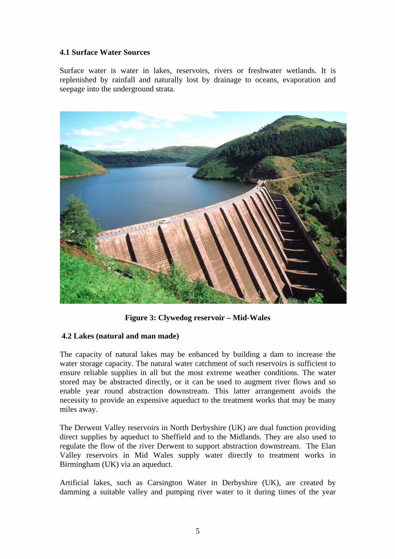
The second stage involves the destabilization of the fine solids in colloidal suspension. The negatively charged colloidal particles are attracted to the positively charged coagulant particles to form larger particles that will settle, but only very slowly. In the third stage, gentle agitation is used to cause these coagulated solids to come together to form larger, aggregates called flocs that are readily settled out. The process is called flocculation The processes of coagulation and flocculation are illustrated in Figure 15. The fourth and final stage is the removal of the flocculated solids, which takes place in a tank called a clarifier. An example of a hopper-type clarifier tank is shown in Figure 16. The chemically dosed water from the flocculator enters the base of the tank and travels upwards at decreasing speed due to the conical shape of the tank. This encourages the initially small flocs to coagulate into larger flocs. The rate of flow is such that a floc blanket is formed below the surface of the water at the level at which the upward flow of the water and the floc settling rate are equal. The clarified water leaves the top of the tank and passes on to the filtration stage. Excess floc accumulates in the sludge hopper and is periodically removed to ensure that the floc blanket does not build up too much and that it always remains below the water surface.
Inlet
Outlet

19
Figure 15: The Coagulation and Flocculation Process
Dissolved air flotation is a less widely used alternative process in which dissolved air in the form of fine bubbles is used to cause the flocs to float to the top of the tank where they can be removed by skimming or overspilling.
Negatively charged colloid particles
Destabilised colloid
(electrically neutral)Positively charged
coagulant
Negatively charged colloid particles repel one another and will not combine into larger,settleable particles. Addition of a positively charged coagulant destabilizes the colloidparticles by neutralizing their negative charge. With gentle agitation the colloidparticles then coagulate to give larger, settleable particles. Coagulants commonly used include: aluminium sulphate, ferrous sulphate, ferricsulphate, etc. A polyelectrolyte may be added to further aid coagulation
20
Decanting Clarified channel
Automatic sludge bleed pipe
Sludge blanket level
Raw water Inlet pipe
Bottom sludge extractor pipe
Sludge concentrator cone
Valve
Figure 16: A Hopper Type Clarifer Dissolved air flotation (DAF) is a less widely used alternative process in which dissolved air is introduced at the base of the clarifier. The fine bubbles attach to the flocs causing them to float to the top of the tank where they can be removed by either overspilling or skimming. 8.2 Filtration There are three principal types of filtration process used in drinking water treatment.
• Slow sand filters – this process has been briefly described above. • Pressure filters - in fairly common use. • Rapid gravity sand filters – the most commonly employed filtration system.

21
Pressure filters Pressure filters tend to be used for treating upland reservoir or, where necessary, groundwaters. They usually comprise steel cylinders mounted either vertically or horizontally and containing a bed of coarse sand over gravel through which the water is passed under pressure. The solids accumulating in the filter media are periodically removed by backwashing with clean water. Often pressure filtration of waters from upland reservoirs is not preceded by a clarification stage so, where necessary, chemical coagulants may be added to the feed water to assist solids removal. Where iron and/or manganese must be removed from groundwater, pressure filters may be employed to remove the precipitated compounds after chemical treatment. Rapid gravity sand filters Rapid gravity sand filtration is by far the most common system used in UK water treatment practice. The vast majority of filters are designed for down-flow filtration with up-flow backwash to remove accumulated solids (see Figure 17). The filter media may be a single grade of silica sand supported on a layer of coarser sand and gravel. Multimedia systems may be employed but these are outside the scope of this Guide. As solids accumulate in the filter media the level of water rises in the filter tank since a greater head is needed to overcome the resistance to filtration. At a prearranged level the water inflow is turned off and the water level is allowed to fall to the level of the outlet weir. Compressed air is then blown up through the bed to loosen the lighter organic solids from the media following which back-wash water washes these solids over the weir to waste. The filter is then returned to service.

22
sand
gravel
Inlet
Backwash waste
Filtered water
Valves Air and
backwash water
Figure 17: A Rapid Gravity Sand Filter (side elevation)
8.3 Disinfection There are various ways of disinfecting water supplies. Figure 18 gives examples of the agents used.

23
Figure 18: Methods used for the disinfection of water.
The disinfection method used will depend on several factors:-
• Effectiveness in destroying micro organisms. • The nature of the water to be treated. • The volume throughput of water to be disinfected. • Cost • The ease of handling of the disinfectant agent. • The health and safety of operatives. • Any residual needed in the distribution system. • The formation of any harmful bi-products of disinfection.
Of the available disinfectants chlorine is the most commonly employed in public water supply systems in the UK. It is commonly supplied as a gas or liquid or may be generated on site. It is also available as a solution of sodium or calcium hypochlorite, which is usually used for small source disinfection, for example, wells and springs.
Disinfectant agent Use Efficiency Chlorine Commonly used in the
treatment of water for public supply.
Excellent disinfectant action. A chlorine residual may be retained in the distribution system.
Chloramines Used where distribution systems are long since residual persists.
Formed when chlorine reacts with ammonia. Less efficient disinfectant but residual persists longer in distribution.
Chlorine dioxide Not in common use in the UK.
More powerful disinfectant than chlorine and persists in distribution.
Ozone Used for the disinfection of lowland river waters when pesticides are present. Not commonly used in the UK, but use increasing.
Effective disinfectant that avoids formation of THMs. No residual in distribution.
Ultraviolet light Used for small water supplies.
Effective disinfectant but adversely affected by turbidity and fouling and gives no residual in distribution.
Silver filters Used for individual water supplies where untreated water quality is good.
Alright for small domestic water supplies with high quality raw water.
Bromine and iodine Not usually used for the disinfection of public water supplies
Behave similarly to chlorine but are not used in public water supply

24
Ozone is expensive to generate and rapidly decays leaving no residual, however this powerful oxidant/ disinfectant is useful at larger works treating lowland river water. Its application early in the process chain, rather than use of chlorine, avoids the production of harmful trihalomethanes. Ozone is also said to aid the clarification stage of the treatment process. Where ozone is used it is usual to employ activated carbon filtration later in the process chain to remove any residual products of ozonolysis. This combination of ozone and activated carbon processes is very effective in the removal of pesticide residuals present in the raw water as a result of agricultural and/or industrial activity upstream. The treated water is then chlorinated so as to provide a small residual in the distribution system. The use of ozone and activated carbon is commonly called advanced treatment in the UK, but is quite common on the continent. In this guide only disinfection using chlorine will be considered in detail. 8.4 Chlorination There are four principal chlorination processes in common use in the UK.
• Simple chlorination – where the water quality is good. • Breakpoint chlorination – for waters of lower quality. • Superchlorination and dechlorination – for poor quality waters. • Chloramination – to maintain a residual in extensive distribution systems
with long residence times. When chlorine residuals are measured they can be either free chlorine or, when partly or wholly combined with ammonia compounds occurring in water, as total chlorine which is the sum of the free and combined chlorine. The chloramines formed by combination with ammonia are less effective disinfectants but persist longer in treated water systems. Simple chlorination Commonly used on good quality water from deep boreholes where the organic and bacterial content and thence the chlorine demand is low. A dose rate of 0.1- 0.2 mg/l with a contact time of 30 minutes is usually sufficient and is often merely a precaution. The chlorine is present exclusively in the free form. Breakpoint chlorination Breakpoint chlorination is used for the disinfection of poorer quality waters containing chemical as well as microbiological contaminants. It takes advantage of the fact that chlorine will preferentially react with any chemical contaminants present before eliminating micro-organisms. The detailed chemistry is complex and outside the scope of this Guide, the following being a simplified outline. Initially, as chlorine is added to the water, there is little residual chlorine in the water as the chlorine reacts with chemicals in the water, (see figure 19). The total residual chlorine then rises as the chlorine reacts with ammonia in the water producing

25
chloramines that contribute to the measured total chlorine residual. Hydrogen in ammonia is progressively replaced by chlorine as follows.
NH3 NH2Cl NHCl2 NCl3
After peaking the residual chlorine level falls as further chlorine reacts with the chloramines destroying them.
2NH2Cl + Cl2 N2 +4HCl The residual chlorine falls to a minimum called the breakpoint at which all the chloramines have been destroyed following which it begins to rise once more and is controlled so that the target level, shown in red, is not exceeded. Beyond the breakpoint disinfection is at its most efficient. Super chlorination For high risk waters, such as those from lowland rivers, super chlorination may be needed to ensure that full disinfection is achieved. Here the chlorine dose is increased beyond the breakpoint to give a chlorine residual level well in excess of the target level and thus ensure complete disinfection. The excess residual chlorine is then reduced to the target level by dechlorination usually through the addition of sulphur dioxide. Chloramination Where water takes a long time from treatment works to the ends of the distribution system ammonia is sometimes added at the works to combine with the chlorine to produce chloramines which can persist throughout the system although they are less effective disinfectants than free chlorine.

26
Chlorine dose
Res
idua
l chl
orin
e le
vel
Residual chlorine Breakpoint Dechlorination to required target level residual chlorine target level
Figure 19: Chlorination types Contact time Disinfection effectiveness is influenced by the disinfectant concentration, the temperature and the contact time. The time taken for chlorine to kill micro-organisms can be up to 4 times quicker in summer than in winter. A minimum time is therefore needed for the chlorine to be in contact with the water to ensure complete disinfection. This ranges from 20-30 minutes for good quality upland reservoir waters to about 90 minutes for high risk lowland river waters. There may also have to be some adjustment to the contact time to take account of the pH (acidity or alkalinity) of the water. Contact tanks are of similar design to the static flocculator shown in Figure 14 and promote intimate mixing of the chlorine and water. Normally two such tanks are provided for use in parallel thus allowing maintenance tasks to be performed in one whilst disinfection takes place in the other. 9.0 Water Distribution Once water has been treated to meet quality standards it is ready for distribution to consumers via the water distribution system. A public water distribution system is a complex array of trunk mains, service reservoirs, local mains and service pipes culminating at the consumers’ tap. Figure 20 provides a simplified example.

27
Figure 20: Schematic of a Water Distribution System 9.1 Service Reservoirs Water is normally delivered to consumers by force of gravity so, unless the source and treatment works are sufficiently higher above the area to be served, the water must be pumped via rising mains to elevated service reservoirs which provide a head of pressure for piping to consumers. Water treatment works output cannot be varied in response to short term fluctuations in demand so service reservoirs are also used to provide buffer capacity against such variations in water demand, for example, diurnal changes, week and weekend demands. This allows smaller rising mains to be used to feed the service reservoir than would be needed to serve customers without them. Service reservoirs are covered reservoirs often located at the top of a hill to provide the elevation to gravity feed water to consumers at the required pressure. The roofs incorporate a water proof membrane to prevent ingress of rainwater and they are usually grassed over to provide insulation from weather variations and to improve aesthetic appearance. They require ventilation to allow water levels to rise and fall with demand, and vents must be covered to prevent ingress of insects and small animals. In flat terrain elevated tanks, called water towers, are used as service reservoirs as shown in Figure 21.
River
Water treatment plant
Rising main
Service reservoir
Ground level
Distribution mains

28
Figure 21: Water towers under construction
9.2 Mains and Services As demanded, water is fed under gravity from the service reservoir via distribution mains to the area to be served. The distribution network is divided to metered zones so that the volume of water supplied is known – this helps with network modelling and in tracing leakage in the system. Where the service reservoir is so high above parts of the distribution system that excessive pressures are generated it may be necessary to incorporate pressure reducing valves to reduce leakage and pipe bursts and provide acceptable water pressure to premises. Water enters consumers’ premises via a service pipe, see Figure 22, which comprises two parts:-
• the communication pipe from the water main in the street to the boundary stop-tap.
• the supply pipe that carries the water from the stop-tap into the consumer’s premises
The communication pipe is the responsibility of the water company (or water undertaker) whilst the supply pipe has been the responsibility of the householder (customer).

29
Two or more older properties may share a supply pipe and be jointly responsible. Where a meter is installed it is at the boundary stop tap so that any leakage on the consumer’s premises is measured, but water companies in many circumstances offer free leak detection and free supply pipe repair for household consumers.
Figure 22: Schematic of a Water Service 9.3 Leakage control Leakage from distribution systems must be minimised to prevent the over-abstraction of water sources with consequent environmental damage. Leakage can arise not only from significant bursts but also from seepage from joints and small leaks. There is an economic point at which the cost of further leakage control outweighs the cost of providing the leakage water. At that stage the potential environmental problems caused by over-abstraction become a consideration when controlling leakage. The distribution system is divided into zones where the water entering can be metered. These meters may be read at quiet times when water demand in the zone would be expected to be minimal. Excess water demand at such times may indicate a leak in the system. Listening devices are used to detect water flow in mains and so locate leaks, which are then scheduled for repair. It is estimated that some 25% of all leakage is from supply pipes belonging to householders. In the interest of leakage reduction, some water companies will repair them free of charge or contribute towards their renewal.
Water Main
Stop Tap And
Water Meter At Property Boundary
Communication Pipe
Supply Pipe
Ground - level

30
9.4 Levels of Service and Water Quality Issues As stated earlier, the Drinking Water standards are applied at the consumers’ tap. Water suppliers must ensure that there is no deterioration of water quality as it passes through the distribution system that would cause these standards to be breached. Surveillance is maintained by regular sampling of the water leaving the treatment works and all through the distribution system including at customer taps. Should problems threatening public health present themselves immediate remedial action is taken. Great care is also taken to avoid any contamination of water in supply when maintenance work is undertaken on the distribution system. The Drinking Water Inspectorate in England and Wales is responsible for audit of the water suppliers’ performance to ensure that the water supplied is compliant with quality standards and is acceptable to consumers. Each major water supplier has thousands of kilometres of water mains to operate some of which may be over 100 years old and each has a programme for mains replacement. Factors that prioritise a main for replacement include frequency of bursts, leakage, internal corrosion, etc. Internal corrosion of iron mains can result in discoloured water at the consumer’s tap. Whilst not a health hazard, discoloured water is aesthetically unpleasant and in bad cases can stain sanitary fittings and washing. A badly corroded water main may have its water carrying capacity reduced by internal nodules of corrosion products and as a result water pressure may be reduced in the area it serves. These nodules may trap any organic suspended material present in the water thus forming a habitat for small organisms such as the waterlouse (Asellus aquaticus). Although these are harmless they may cause distress if they appear at the consumer’s tap. In addition to the water quality standards, water suppliers also have levels of service standards for such matters as water pressure, discolouration, etc., to be achieved at the consumer’s tap. Continuing improvement in levels of service is a key objective of water supply management. In England and Wales, the Consumer Council for Water (www.ccwater.org.uk) provides a link between consumers, policy makers and water companies and responds to policy consultations on behalf of consumers. Ofwat (www.ofwat.gov.uk) is the water industry regulator in England and Wales charged with the regulation of water and sewerage service prices to consumers and the service standards, including water and effluent quality standards, they must provide within the price settlement. This includes the agreed capital works programme needed to maintain existing infra-structure and, where necessary, to provide new.

31
10.0 Reflections The journey of water from source to consumer is long and arduous and yet the water supplied must meet drinking water quality and levels of service standards at the consumer’s tap. There must also be sufficient water available to meet demand under a very wide range of climatic conditions. Water distribution systems in the UK extend over tens of thousands of kilometres and have been laid down over the past 150 years; therefore there has to be an ongoing programme of mains replacement prioritised to deal with the least reliable areas of the system first. Over the past 150 years, the water industry has made a major input to improved public health compared to the early years of the 19thC when waterborne disease was rife and life expectancy short. 11.0 Glossary of terms Advanced water treatment: commonly used term in the UK when GAC filtration and/or ozone disinfection are used in drinking water treatment. Aquifer: water held in fissures in permeable, subterranean rock strata through which it is free to move. Bank-side storage reservoir: a reservoir created alongside a river from which water is abstracted and adjacent to a water treatment plant. Provides a strategic reserve for when river flows are low or the river is contaminated and acts as a buffer to normal variations in river water quality. Where retention times are long bankside storage may provide significant water quality improvement. Chloramination: the addition of ammonia to combine with residual chlorine to produce chloramines that are longer lasting disinfectants. Chlorination: the use of chlorine as a disinfectant in water treatment. Clarification: The process of removal of flocculated solids from water during treatment. Coagulation and flocculation: the physicochemical process whereby colloidal solids in untreated water are coagulated and flocculated into larger particles that can readily be removed. Colloid: a suspension of small charged particles in water stabilised by the repulsion between like electrical charges on the particles. Communication pipe: that part of a service pipe that connects the water main in the street to the stop-tap at the boundary of the consumer’s property.

32
Cone of depression: the water table drawdown induced by pumping at the base of a borehole which takes the form of a cone. Consumer Council for Water (www.ccwater.org.uk) represents the interests of water consumers in England and Wales. Disinfection: the process of ridding water of harmful micro-organisms including bacteria before it enters the distribution system. Distribution: the system of pipe-work, service reservoirs and pumping plant that delivers water to the consumer. Drinking water quality standards: the quality standards set out in the EU Directive on Drinking Water as transposed into UK law, and any other nationally adopted standards. Drinking Water Inspectorate: (www.dwi.gov.uk) the body that provides independent reassurance that water supplied in England and Wales is safe, complies with statutory drinking water quality standards and is acceptable to consumers. Filtration: the process by which residual flocculated solids following clarification are removed from the water during treatment. Flocculator: a vessel designed to induce intimate mixing of flocculant chemicals with the water prior to the clarification stage of treatment. Granular activated carbon (GAC): granules of carbon that provide a very large surface area for the adsorption and absorption of organic molecules, such as pesticides and the small organic molecules produced when ozone is used in water treatment. Groundwater: water that has percolated through the ground and is held in fissures in the rock strata. Hardness: originally defined in terms of the ease with which a soap lather may be formed in the water under test and now characterized by the concentration of calcium and magnesium carbonates and sulphates in the water. Indicator bacteria: a group of bacterial species which, although in themselves not harmful, indicate the possibility that harmful micro-organisms may be present. Impounding reservoir: a reservoir formed by damming off an area of low lying land which is allowed to flood. Leakage control: measures taken to reduce the quantity of water lost from the water distribution system. Levels of service: targets designed to ensure appropriate service to customers, for example, guaranteed minimum water pressure, response times to bursts, etc.

33
Mains and services: water is brought to a locality through water mains usually in the street, service pipes connect the property served to the water mains. Ofwat (www.ofwat.gov.uk): the economic regulator for the water and sewerage industry in England and Wales. Ozone: a compound of oxygen formed by passing it through a silent electrical discharge, it is a powerful oxidizing agent and bactericide, but rapidly degrades leaving no residual. Pressure reducing valve: a mechanical device in a water main which reduces excessive pressure while maintaining flow. Rising main: A main transferring water under pressure to a higher point, such as from a treatment works to a service reservoir. Saline intrusion: the intrusion of saline water into a freshwater aquifer often as a result of over-abstraction from boreholes in a coastal region. Schmutzdecke: the biologically active zone formed in a slow sand-filter that aids water purification. Service reservoir: A reservoir located in the distribution system to provide a strategic water reserve and to smooth out response to daily variations of customer water demand. Service pipe: the pipe connecting the water main to a consumer’s premises. Slow sand filtration: slow passage of water through a sand filter in which biological purification takes place. Supply pipe: that part of the service pipe which is on the consumer’s side of the stop tap at the boundary of his property. Surface water: all water on the surface of the ground, for example lakes, rivers, ponds, etc. Water demand: the total volume of water in a given time required to meet all customer requirements. Water resources: comprise all the water available for man to exploit; sea, lake, river, groundwater, etc. Water sources: water resources that have been developed for use by man. Water table: the natural level of water in an aquifer.

34
12. Further Information Sources FWR Guides FR/G0001 EC Water Framework Directive FR/G0002 A Householder’s Guide to Water Supply and Sewerage FR/G0003 The Evolution of River Basin Management in England and Wales FR/G0004 Drinking Water Standards and Guidelines FR/G0007 Householder’s Guide to Private Water Supplies FWR Reviews of Current Knowledge (ROCKS) FR/R0002 Eutrophication in Fresh Waters FR/R0003 Endrocrine Disrupters in the Environment FR/R0004 Legionella in the Environment FR/R0005 Cryptosporidium in Water Supplies FR/R0006 Giardia in Water Supplies FR/R0007 Causes of Copper Corrosion in Plumbing Systems FR/R0012 World Water: Resources, Usage and the Role of Man-Made Reservoirs FR/R0013 Desalination for Water Supply For a wide range of information on water and related environmental issues visit the FWR website at www.fwr.org .