downloads.deusm.comdownloads.deusm.com/designnews/coffeemugwarmer... · web viewallied electronics...
TRANSCRIPT
Coffee Mug Warmer by Induction Heating
Sajjad Haidar
Surrey, BC, Canada, Email: [email protected]
Most of the coffee mug warmers available in the market utilize resistive heating. These warmers can be used with ceramic mugs or outer-body stainless steel mugs, but they aren't suitable for stainless-steel mugs that use a plastic outer cover for insulation.
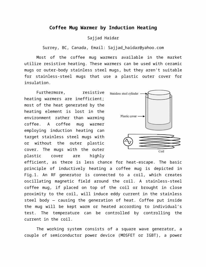
Furthermore, resistive heating warmers are inefficient; most of the heat generated by the heating element is lost in the environment rather than warming coffee. A coffee mug warmer employing induction heating can target stainless steel mugs with or without the outer plastic cover. The mugs with the outer plastic cover are highly efficient, as there is less chance for heat-escape. The basic principle of inductively heating a coffee mug is depicted in Fig.1. An RF generator is connected to a coil, which creates oscillating magnetic field around the coil. A stainless-steel coffee mug, if placed on top of the coil or brought in close proximity to the coil, will induce eddy current in the stainless steel body — causing the generation of heat. Coffee put inside the mug will be kept warm or heated according to individual’s test. The temperature can be controlled by controlling the current in the coil.
The working system consists of a square wave generator, a couple of semiconductor power device (MOSFET or IGBT), a power supply and a working coil with a capacitor in parallel. The basic block diagram of the entire system is shown in Fig.2.
Fig.2. The basic block diagram of the coffee mug warmer.
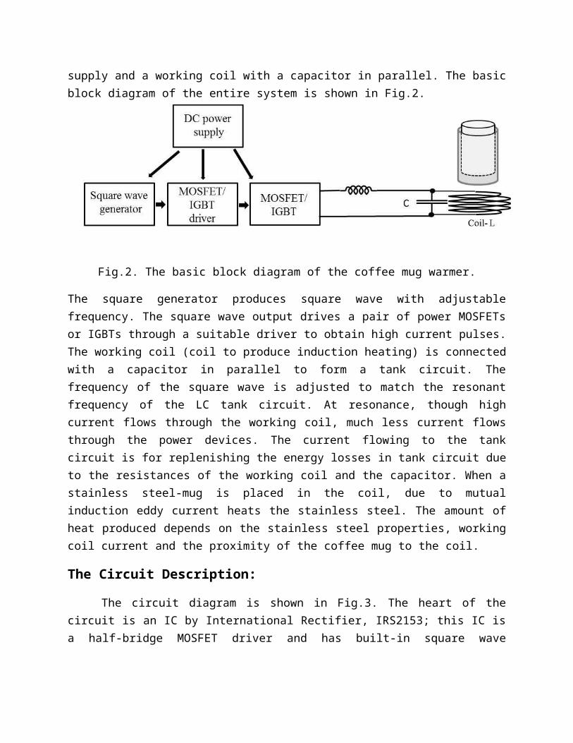
The square generator produces square wave with adjustable frequency. The square wave output drives a pair of power MOSFETs or IGBTs through a suitable driver to obtain high current pulses. The working coil (coil to produce induction heating) is connected with a capacitor in parallel to form a tank circuit. The frequency of the square wave is adjusted to match the resonant frequency of the LC tank circuit. At resonance, though high current flows through the working coil, much less current flows through the power devices. The current flowing to the tank circuit is for replenishing the energy losses in tank circuit due to the resistances of the working coil and the capacitor. When a stainless steel-mug is placed in the coil, due to mutual induction eddy current heats the stainless steel. The amount of heat produced depends on the stainless steel properties, working coil current and the proximity of the coffee mug to the coil.
The Circuit Description:
The circuit diagram is shown in Fig.3. The heart of the circuit is an IC by International Rectifier, IRS2153; this IC is a half-bridge MOSFET driver and has built-in square wave oscillator. Capacitor CT and Resistor RT determines the oscillation frequency expressed by:
f≈ 1/(1.453 ×RT ×CT)
With capacitor CT= 0.01 F and RT from 1K to 101K (variable), we find frequency, f adjustable from 688 Hz to 68.1 kHz. To make the circuit operable from 24V to 48V, a ~21 V voltage regulator is implemented using a Zener diode D1 and a transistor Q3. Two outputs (Ho and Lo) of the IC is such that, half the cycle transistor Q1 is ON and Q2 is OFF, the other half cycle the opposite occurs. There is a little gap between the ON times of Q1 and Q2 which is called the dead time for a safe operation. At the output of the power MOSFETS, where Source of Q1 and Drain of Q2 joins we get a square wave voltage; the lowest is 0 V and the peak is the supply voltage. A 30F capacitor, C3 is used to filter out the DC component; at the output of C3
Fig.3. Schematic diagram of the coffee mug warmer
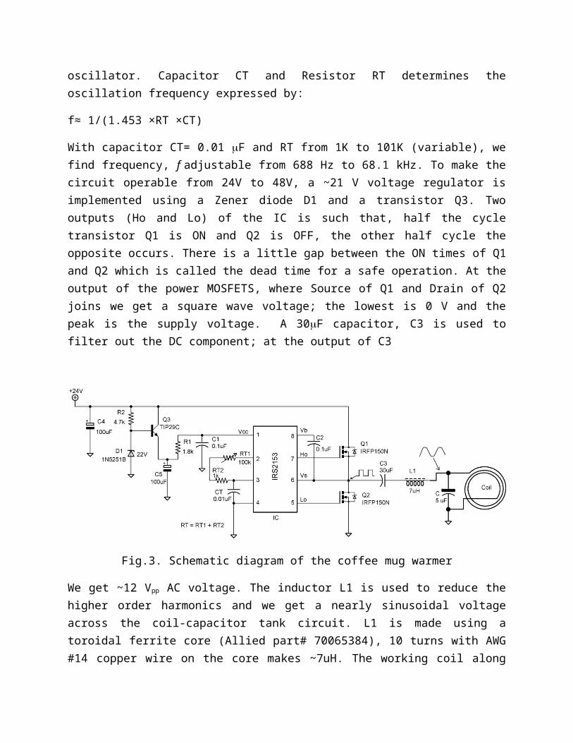
We get ~12 Vpp AC voltage. The inductor L1 is used to reduce the higher order harmonics and we get a nearly sinusoidal voltage across the coil-capacitor tank circuit. L1 is made using a toroidal ferrite core (Allied part# 70065384), 10 turns with AWG #14 copper wire on the core makes ~7uH. The working coil along with the 5F bipolar (film) capacitor is connected at the other end of the inductor, L1.
Parts list-1:
Qty. Value Parts Description
Allied ElectronicsPart#
1 IRS2153 IC H-Bridge, MOSFET Driver, Oscillator
70017317
1 0.01uF CT Capacitor 70195788
2 0.1uF C1, C2 Capacitor 70195939
1 1.8k R1 Resistor 70024412
1 100k RT1 Potentiometer 70154227
2 100uF C4, C5 Polarized Capacitor 70187364
1 1N5251B D1 Zener Diode 70061648
1 1k RT2 Resistor 70522113
1 30uF C3 Capacitor 70233336
1 4.7k R2 Resistor 70183451
1 5 uF C Capacitor 70233333
1 7uH L1 Toroidal Ferrite Core 70065384
2 IRFP150NPBF Q1, Q2 N-Channel MOS FET 70017034
1 TIP29C Q3 NPN Transistor 70013794
1 24 V ZPSA60-24 Power Supply 70177449
1 TH-K-1-0-5 Thermocouple 70209691

Parts list-2:
Qty. Description Allied ElectronicsPart#
1 Box 701487331 Copper Clad Board: 5” x 3” 70125831 4 Banana plug 700903144 Banana Jack 700902062 Terminal 700544222 Heat sink 70115147 Other items needed: screws, hookup wire, soldering lead, cable ties etc.
Build instructions:
1. As some lines carry high current, it is better to make a printed circuit board (PCB) for the circuit. For making PCB, one can use EAGLE CAD as it is free (with a board-size limitation). Capacitor C3 and Inductor L1 (Fig.3), can be kept out of the PCB, as these large component can increase the PCB size beyond the limit. After drawing the schematic in EAGLE, one can also add two terminals (Allied part # 70054422) for power input and coil output. Once the schematic is drawn, it is easy to switch to board in EAGLE. The tutorial comes with EAGLE will guide someone how to finish the PCB layout. After the PCB layout is designed, one can send the PCB files to any small PCB making companies to get it done. Or anyone interested in making their own can find lot of DIY PCB making instructions in the internet.
2. Next step would be to put all the components in place on the PCB and solder these well. As the two MOSFETs (Q1 and Q2) will get heated after few minutes of operation, two heat sinks should be attached to Q1 and Q2. The populated PCB can now be placed inside the box. Capacitor C3 can be mounted inside the box-wall by some screws. After mounting the potentiometer and the banana jacks on the box, wire should be connected to the banana jacks for the power input and coil output. The PCB inside the box along with other parts is shown in Fig.4
Fig.4. The populated PCB inside the box.
3. Working coil: The coil is made with AWG #12 copper wire (plastic coated or enamelled). Coil diameter is chosen ~10 cm, which is little bigger than many of the coffee mugs available in the market. Number of turns is ~7, after the coil is wound; several cable ties are used to make the coil tightly packed as shown in Fig.5. The resistance and the inductance of the coil were measured using an LCR meter; the values found are, inductance: ~ 9.5H and resistance R: ~0.015. A low ESR film capacitor of value, 5 F was connected in parallel to the coil as shown in Fig.5. The calculated resonant frequency of the tank circuit is, fr ~ 23.1 kHz.
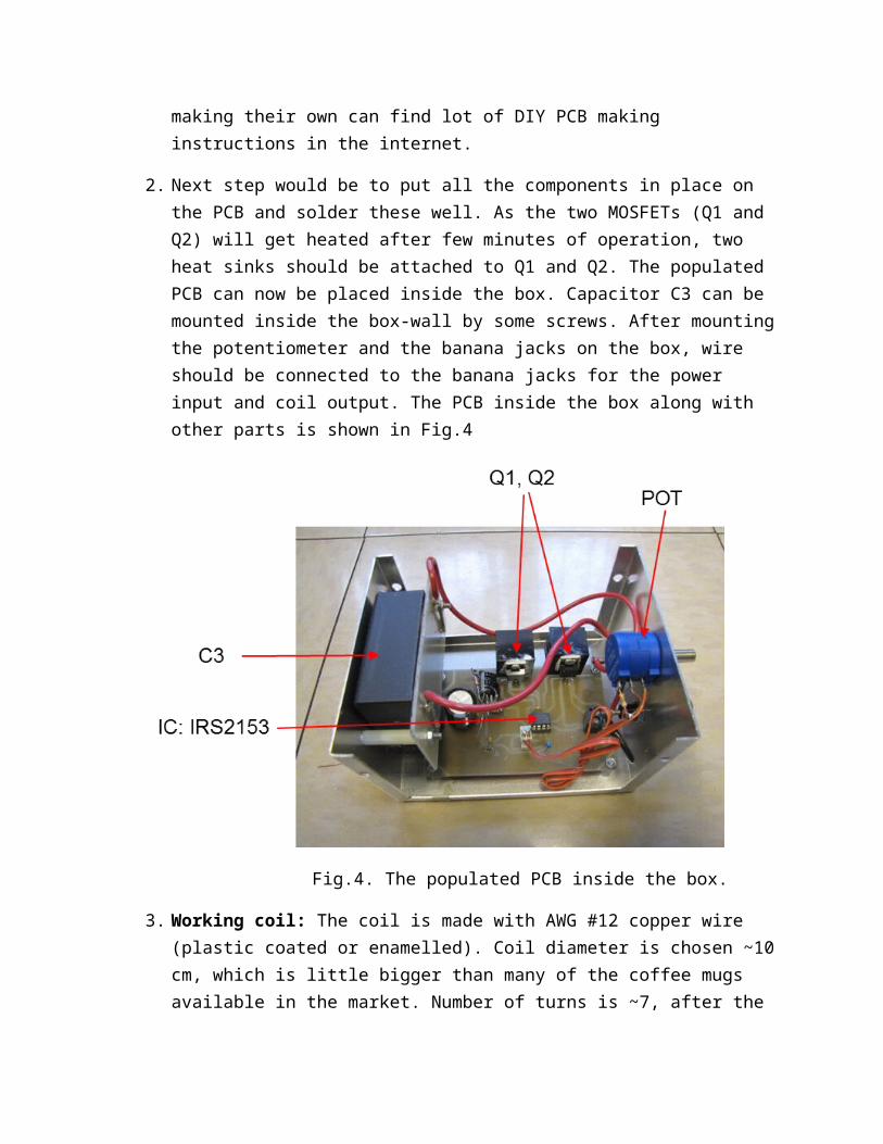
Fig.5. The working coil with a capacitor in parallel.
Testing the Induction Warmer:
The coil was connected to the circuit; an ammeter was also connected in series with the 24 V, 2.1 A power supply. Initially the coil was kept out of touch of the coffee mug or any other metal object. The potentiometer, RT1 is slowly increased from minimum value and the ammeter reading was observed. Initially the current was high (~ 2 A) as the frequency approaches the resonant frequency current goes down, at around the resonant frequency the current is the minimum. This should be the set point of the potentiometer, RT1 at this minimum current. With no metal object close to the coil, the minimum current found was ~0.12 A. Now with a plastic covered stainless steel- coffee mug in the coil gives rise to higher current. For the mug I used, gave us a current of ~ 0.59 A. Of course, different types of mugs will produce different current, thereby varying amount of power dissipation in the mug. The mug I used was of 9cm diameter made by Thermos. Instantly after putting the mug in the coil we can feel the heat inside the mug by touching the wall. Though an oscilloscope is not essential to test the circuit, however to get a better idea about the waveforms and frequency we can use one. The voltage waveforms found before and after the inductor L1 is shown in Fig. 6. After L1, the higher order harmonics are reduced to a large extent, the sharp voltage spikes are also gone. When the mug was in the coil, due to induction the voltage across the coil was little reduced.
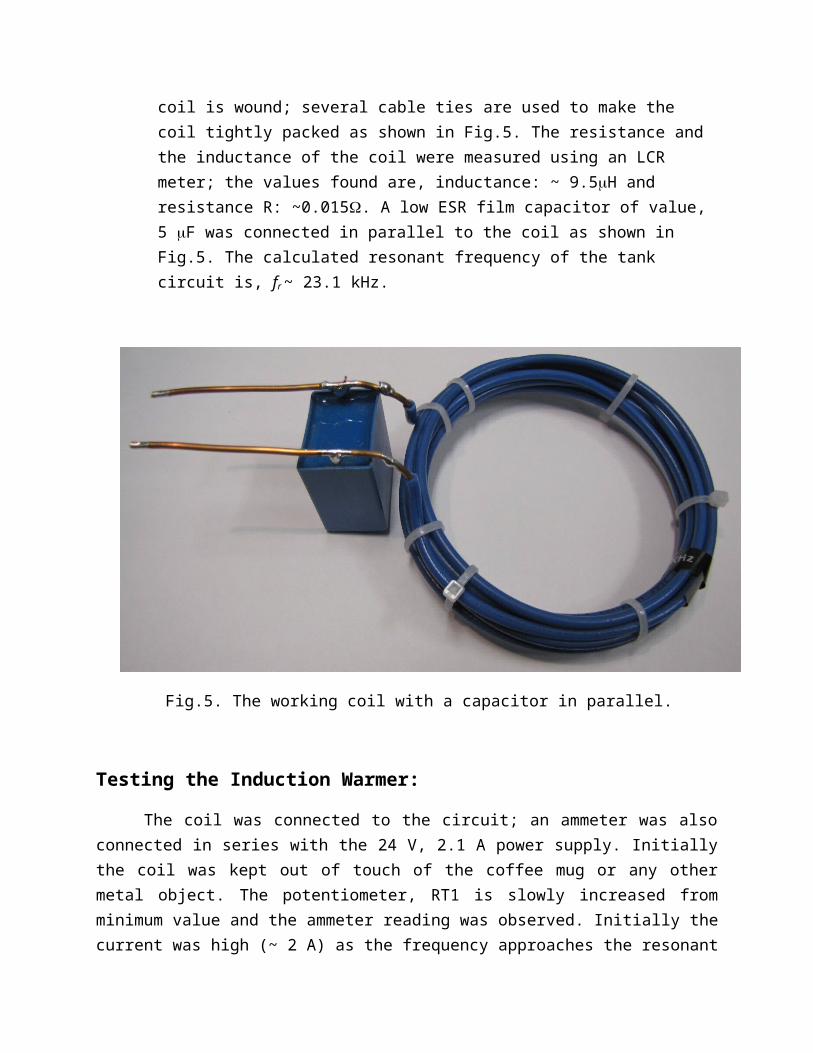
Fig.6. Oscilloscope waveforms across the coil-capacitor tank circuit and before the inductor L1
After the tuning was done, the coffee mug was filled with a volume of water ~ 300 ml and put in the coil. A thermocouple was also inserted in the mug, the tip of which was touching the water. The lid of the mug was put on and the power supply was connected. The current remained ~0.59 A with the mug in. The test setup is shown in Fig. 7. Temperature was recorded since the power was switched ON. Temperature slowly rose to ~72 oC in an hour and remained nearly unchanged at ~ 80 oC after a prolonged period. At ~80 oC the rate of heat generated by induction heating in the mug equals the rate of heat escaping the mug to the ambient. This means that an already warm coffee will remain at ~70 – 80 oC with this gadget. If the same circuit is powered by a 48V supply instead of 24 V; with and without the mug the DC power supply-current was 0.27 A and 1.28 A, respectively. With 48 V supply temperature of 300 ml water quickly increased and to reach 100 oC, it took only 35 minutes. The rise of temperature with time for 24V and 48 V supplies are shown graphically in Fig.8
Fig.7. The test setup.
Fig.8. Temperature rise of 300ml of water in a coffee mug. Black and blue lines are for operation with 24 V and 48 V power supplies, respectively.
More than 300 ml coffee was used instead of water; with 24 V supply warm coffee was enjoyed for a prolonged period of time.