viewer license agreement · 2020-02-19 · viewer license agreement you must read this license...
TRANSCRIPT

Viewer License AgreementYou Must Read This License Agreement Before Prceeding.
This Scroll Wrap License is the Equivalent of a Shrink Wrap Click License,⇒ A Non-Disclosure Agreement that Creates a “Cone of Silence”.
By viewing this Document you Permanently Release All Rights that would allow you to restrict theRoyalty Free Use by anyone implementing in Hardware, Software and/or other Methods in whole orin part what is Defined and Originates here in this Document. This Agreement particularly Enjoins theviewer from: Filing any Patents (À La Submarine?) on said Technology & Claims and/or the use ofany Restrictive Instrument that prevents anyone from using said Technology & Claims RoyaltyFree and without any Restrictions. This also applies to registering any Trademarks including but notlimited to those being marked with “™” that Originate within this Document. Trademarks andIntellectual Property that Originate here belong to the Author of this Document unless otherwisenoted. Transferring said Technology and/or Claims defined here without this Agreement to anotherEntity for the purpose of but not limited to allowing that Entity to circumvent this Agreement isForbidden and will NOT release the Entity or the Transfer-er from Liability. Failure to Comply with thisAgreement is NOT an Option if access to this content is desired. This Document containsTechnology & Claims that are a Trade Secret: Proprietary & Confidential and cannot betransferred to another Entity without that Entity agreeing to this “Non-Disclosure Cone of Silence”V.L.A. Wrapper. Combining Other Technology with said Technology and/or Claims by the Viewer isan acknowledgment that [s]he is automatically placing Other Technology under the Licenses listedbelow making this License Self-Enforcing under an agreement of Confidentiality protected by thisWrapper.
The contents of/and this Document are released under the following licenses so long as thisAgreement remains attached to any and all files, papers, etc... that contain any said Technologyand/or Claims. Any Hardware manufactured with said Technology and/or Claims must contain abrief message, e.g. “V.L.A. This Hardware contains Technology and/or Claims that are Licensed forUnrestricted and Royalty Free Use. Any knowledge gained by viewing this hardware design may notbe used to file any patents, employ restrictive licensing, or interfere with the manufacture, sale anduse of this hardware”.
Software only: GNU General Public License 3.0 (GPL)Hardware (w/ || w/o software): Tucson Arizona Packet Radio TAPR PDF ODT TXT
This Document is licensed under Creative Commons so long as this V.L.A. remains attached to the contents of this document in whole or in part. It may be re-distributed and hosted anywhere.Open Source (CC BY- SA 4.0 ), Proprietary (CC BY-ND 4.0 )
Scrolling past this page is The Point of No Return and Acknowledges that You have Agreed to theTerms above. If you are Unable or Unwilling to Agree to these Terms then Close this Document.
Copyright ©2018 – J. S. Gilstrap – All Rights Reserved.
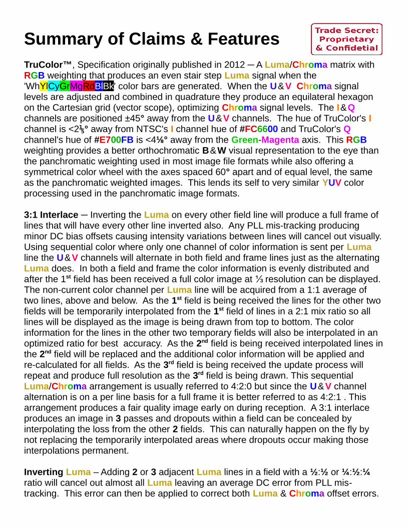
Summary of Claims & FeaturesTruColor™, Specification originally published in 2012 ─ A Luma/Chroma matrix with RGB weighting that produces an even stair step Luma signal when the 'WhYlCyGrMgRdBlBk' color bars are generated. When the U & V Chroma signal levels are adjusted and combined in quadrature they produce an equilateral hexagon on the Cartesian grid (vector scope), optimizing Chroma signal levels. The I & Q channels are positioned ±45° away from the U & V channels. The hue of TruColor's I channel is <2⅕° away from NTSC's I channel hue of #FC6600 and TruColor's Q channel's hue of #E700FB is <4⅛° away from the Green-Magenta axis. This RGB weighting provides a better orthochromatic B & W visual representation to the eye than the panchromatic weighting used in most image file formats while also offering a symmetrical color wheel with the axes spaced 60° apart and of equal level, the same as the panchromatic weighted images. This lends its self to very similar YUV color processing used in the panchromatic image formats.
3:1 Interlace ─ Inverting the Luma on every other field line will produce a full frame of lines that will have every other line inverted also. Any PLL mis-tracking producing minor DC bias offsets causing intensity variations between lines will cancel out visually.Using sequential color where only one channel of color information is sent per Luma line the U & V channels will alternate in both field and frame lines just as the alternating Luma does. In both a field and frame the color information is evenly distributed and after the 1st field has been received a full color image at resolution can be displayed. ⅓The non-current color channel per Luma line will be acquired from a 1:1 average of two lines, above and below. As the 1st field is being received the lines for the other twofields will be temporarily interpolated from the 1st field of lines in a 2:1 mix ratio so all lines will be displayed as the image is being drawn from top to bottom. The color information for the lines in the other two temporary fields will also be interpolated in an optimized ratio for best accuracy. As the 2nd field is being received interpolated lines inthe 2nd field will be replaced and the additional color information will be applied and re-calculated for all fields. As the 3rd field is being received the update process will repeat and produce full resolution as the 3rd field is being drawn. This sequential Luma/Chroma arrangement is usually referred to 4:2:0 but since the U & V channel alternation is on a per line basis for a full frame it is better referred to as 4:2:1 . This arrangement produces a fair quality image early on during reception. A 3:1 interlace produces an image in 3 passes and dropouts within a field can be concealed by interpolating the loss from the other 2 fields. This can naturally happen on the fly by not replacing the temporarily interpolated areas where dropouts occur making those interpolations permanent.
Inverting Luma – Adding 2 or 3 adjacent Luma lines in a field with a ½:½ or ¼:½:¼ ratio will cancel out almost all Luma leaving an average DC error from PLL mis-tracking. This error can then be applied to correct both Luma & Chroma offset errors.

Inverted U Channel – Inverting the Chroma U channel in relation to the V channel during transmission will only cause saturation changes in the I channel but not the hue if a DC tracking error is present. The DC error will cause both –U & V, between where Iis located, to increase or decrease in unison. However for the Q channel the hue will be primarily affected with some minor saturation changes. This is more desirable than having the I channel affected in this way as a ±15° change in Q can produce visually noticeable differences that should be the most tolerable whereas –Q errors are much less noticeable for the same amount of error. The test pattern has Q & –Q colored squares with additional squares at ±15° & ±30° hue deviations.
Time Compressed Chroma – The Chroma signals will be time compressed requiring only ½ the samples required for the Luma per line. During image sampling for transmission the Chroma DotClock will run at ½ speed of the Luma DotClock. During transmission it will produce the same bandwidth as the Luma but its transmission period is only ½ the length of the Luma. During reception the Chroma sample rate willrun at 2 × Luma sample rate to acquire the same number of pixels per line as the Luma. This accounts for the 2 in the 4:2:1 Luma/Chroma ratio. This is mostly Prior Art.
Armstrong PM via QAM – FM is normally used for SSTV modulation to benefit from the capture effect and noise immunity over AM. For Fast Scan TV AM is normally usedwith good results. With AM the sideband energy resembles the modulating signal with no harmonics generated providing greater image detail within the same bandwidth. Both FM and linear PM produce multiple harmonics requiring a wider bandwidth for thesame sideband energy compared to AM. For single tone modulation both FM and PM with the same modulating index produce identical sideband harmonics. One is the integral or derivative of the other. The drawbacks to FM are that the modulation index and S/N decrease as the modulating frequency increases verses PM and is why pre-emphasis is used with FM. Above the pre-emphasis corner frequency the sideband energy starts to resemble that of PM so why not use PM instead. FM has a triangular noise spectrum while PM has a rectangular one. These are well known modulation characteristics and Prior Art.
The goal is to create an angle modulated signal with the sidebands of AM, a rec-tangular noise spectrum, and also benefit from the capture effect and noise immunity ofa limited signal. Using Armstrong PM and not limiting it prior to transmission will produce AM sidebands but also produce a non-linear phase modulation term. In the receiver it can be limited to remove the AM components to benefit from the capture effect and noise immunity but the phase output is non-linear. Tanθ is the correct transfer curve. There are analog circuits that can produce the benefits of a limited signal and output Tanθ in the process, shown later. The Tanθ curve is symmetrical across the modulation range and the phase deviation curve resembles the exposure density curve of film with a larger toe and shoulder and a gradual transition, not unlike that of Tri-X, for the Luma. For the Chroma gamma is applied during transmission and

removed during detection. This phase deviation curve is also similar to µ-Law or A-Lawnon-linear compression used in telephony which can be of benefit here also.Armstrong PM is generated using QAM by modulating the Q vector with the signal and the I vector with a DC level for carrier. The 90° phase differential between I & Q vectors is what creates the phase term. For DSP after detecting the I & Q signals the limited signal benefiting from the capture effect and noise immunity can be calculated as Tan[aTan(Q÷I)].
Master Clock & Pilot Tone Burst – At the receiver the master clock operates at 8× thePilot Tone Burst which is transmitted on the Q channel during the Sync pulses on the I channel. Using a PLL a ÷8 of the master clock is checked against the incoming pilot tone and kept in sync via the loop filter. All timing intervals are defined by a multiple of a cycle of the pilot tone and synchronization checked at every Sync pulse. Chroma is sampled at the master clock rate for RX, and the Luma is ½ of that. If the master clockhas a wide enough tracking range to follow any Doppler shift then everything will stay well synced since it is checked at the beginning of each horizontal line.
Data Header – Previous SSTV systems used a VIS code for identification of different systems and modes. After the beginning tone I guess having a VIS signal modulated in the typical manner would be the norm but having an additional data header is of great benefit. For a system to be dynamically configured on the fly to transmit and receive various image sizes at various speeds within different bandwidths this information must be provided before the image portion is transmitted. Also descriptive information about the image content is also needed. This could amount to a sizable chunk of text and a robust and efficient codec may be needed. The data header must be received before image decoding occurs so its integrity is paramount. QAM32 modulation may be sufficient but using QAM16/COFDM (think DRM) may offer a more robust solution. The default character set is ASCII with UTF-8 being optional.
It is the goal of this document to share this exercise in defining an analog SSTV system and hybrid digital processing with the open source community. Whether or not this will result in a new analog format being created and used at least it is here for a history lesson and education. On the chance that there may be new and creative ideas introduced here that are of some value the viewing license wrapper that has been used is intended to prohibit proprietary interests from claiming sole ownership and/or restricting free use of said ideas. The usual path in protecting ideas are patents, which are costly to obtain within a broken system and in the words of Arthur C. Clark, "A License to be Sued". This is the spirit of this wrapper with the intent in which it has been written. IANAL so the letter of the wrapper may not be perfect.
To extract the test pattern at the end of this pdf highlight image and copy to clipboard then paste into image editor and save image as .png or .bmp in 24-bit.
C-QUAM® is a registered trademark of Motorola.NTSC, PAL, SÉCAM, MAC, RCA , Telefunken & DRM are trademarks not owned by the author.

Not So Slow Scan TV / Widerband FaxThe method for transmitting images via slow scan TV is usually done sequentially with the color components sent separately from the intensity compared to Fast Scan TV where the Luma & Chroma are sent simultaneously per horizontal line, e.g. NTSC & PAL. One system though sends the two color channels separately in time along with each Luma line sending only ½ the number of vertical lines of color providing ½ the vertical resolution, e.g. SÉCAM. A newer analog color system sends all three components separately in a sequence, e.g. MAC.
NTSC – National Television Standards Committee (RCA US) using QAM for Chroma. PAL – Phase Alternation Line (Walter Bruch @ Telefunken DE) NTSC VariantSÉCAM – Séquentiel Couleur Avec Mémoire (Henri de France FR) MAC – Multiplexed Analog Components (UK)
So what would be a good name for this which resembles PAL, SÉCAM & MAC in manyways? A portmanteau of the above?SeMACCMaM ─ Sequential Multiplexed Analog Component Color Matrix And MemoryPronounced 'See Mac Mam', what a mouthful.Maybe PASÉMAC – Phase Alternating Séquential Multiplexed Analog Color.That's a bit much also ... Whatever. Is analog modulation passé now? Maybe,, not.
────────────────────────────────────────────────────────────────────────────────────
Most of the Luma/Chroma SSTV systems use the luminance weighting values of:Y = 0.299×Red + 0.587×Green + 0.114×Blue and scaled CB = (B – Y), CR = (R – Y)
TruColor™ will be used since it produces an equilateral hexagon on the VectorScope.
0.285714 + 0.571428 + 0.142857 = 1
λ = 2×Red÷7 + 4×Green÷7 + Blue ÷7U = √3×(B – λ)÷2 ; V = R – λ
Scaling applied for Armstrong PM:Mλ = 2×Red + 4×Green + Blue – 3½ ; 0–1 ea.MB = K × –UMR = K × V K = 4.715 (4.71502719838196)
The graph to the right shows the Chroma signal asdisplayed on a VectorScope. It produces an equallylevel and spaced color circle, unlike NTSC or PAL, andbetter than YCBCR. I & Q are are located equidistantfrom U & V at 135° & 45° respectively.

In the image above is the phase deviation graph during Luma & Chroma modulation. While the I channel remains static with a DC carrier level of 1 the Q channel when modulated by Mλ, MB & MR will peak at Tan(±74°)=±3½ producing a peak envelope modulation of 3.64 .
In the image above is the starting tone which modulates the envelope at 50% with a peak at 3.64 and with a frequency of Pilot÷10 for 1000 cycles while the Pilot tone is modulated at ±1 on the Q channel. C-QUAM is used for the start tone since the PLL has yet to acquire carrier lock and the envelope should carry a clean tone while also having the Q channel carry the Pilot tone. The same circuit that detects Tanθ for the Luma & Chroma will also detect the C-QUAM Q channel if the envelope signal is supplied to the decoder in place of the un-modulated carrier levels used during image transmission. Next is the data header preceding the field marker castle pulses on the I channel. The castle pulses will have a two level modulation at 1¾ & 2½ providing the field ID depending on which position the peak is at. The 1st all high pulse precedes several progressive lines of color bars test pattern before the 1st field pulse arrives. A 'Pad' or two will precede all Field pulses. The I channel is at 3½ for the horizontal syncand produces the maximum envelope modulation of 3.64 with the pilot tone added. During all sync pulses the pilot tone is modulated at ±1 on the Q channel.
To the right is the Luma & Chroma ModulationTransfer Curve in Green showing the familiar S curve similar to the exposure density of filmand gamma correction for Chroma modulation.The ±100% Red linear line representsmaximum modulation while the ±75% Gold linemodulation is where the majority of Lumaimage modulation will occur and the ±50% Purple line is where the majority of Chromamodulation will be. Only a minimum amount ofimage information exceeds the ±75%modulation levels where it starts to compress alot.

To the right, vertically displayed, is the detailed Luma and Chroma modulation for two lines. The 1st half has boththe Luma and U channel inverted (λ – B) and the 2nd halfhas the non-inverted Luma and V channel (R – λ). At thebeginning of each line are 10 cycles of the Pilot ToneBurst in Green for the horizontal sync. Preceding the Chroma signal, ahead of the sync tone, on the front porchof horizontal blanking, is the Chroma identification pulse.For the U channel it is a +|– order while for the V channelit is –|+. There is an even cadence to the horizontal syncpulses with a missing pulse in the middle of the Lumasignal shown by the Green dash identifying that the nextline will be a Chroma line and to check the front porch toidentify which Chroma channel it is.
The 1st two lines in the image above represent the 16 linesof color bars preceding the 1st field sending both Chromachannels 8 times each. Upon reception this can be usedfor image quality analysis and to auto correct any errors.Line 0 of Field 1 is absent of any Luma but sends the Chroma signal for line 1 which will be averaged with the Chroma signal from line 2 for one of the channels whilethe other comes with line 1. An extra line will also beadded to the to the end of Field 3 for the same reason.Field 1, 1+ #Lines ; Field 2, #Lines ; Field 3, #Lines +1.In the image above to the right is the Chroma channelorder per line. Notice that for both field and frame it is analternating pattern of both –U & V channels providing a fineand even distribution of the Chroma signal.Note: In the vertical image to the right the timing scale accuracy varies somearound the Chroma ID pulses but for all else it is scaled well.
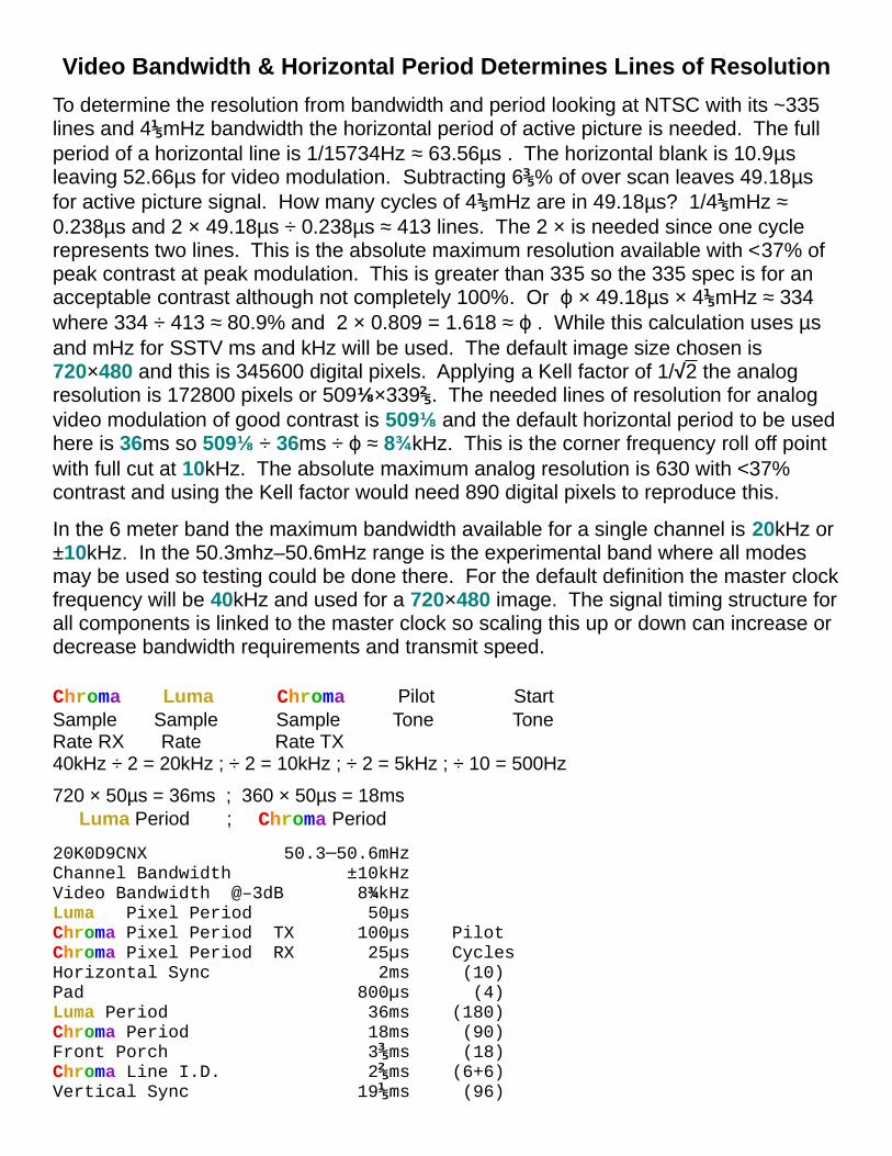
Video Bandwidth & Horizontal Period Determines Lines of Resolution
To determine the resolution from bandwidth and period looking at NTSC with its ~335 lines and 4⅕mHz bandwidth the horizontal period of active picture is needed. The full period of a horizontal line is 1/15734Hz ≈ 63.56µs . The horizontal blank is 10.9µs leaving 52.66µs for video modulation. Subtracting 6⅗% of over scan leaves 49.18µs for active picture signal. How many cycles of 4⅕mHz are in 49.18µs? 1/4⅕mHz ≈ 0.238µs and 2 × 49.18µs ÷ 0.238µs ≈ 413 lines. The 2 × is needed since one cycle represents two lines. This is the absolute maximum resolution available with <37% of peak contrast at peak modulation. This is greater than 335 so the 335 spec is for an acceptable contrast although not completely 100%. Or ф × 49.18µs × 4⅕mHz ≈ 334 where 334 ÷ 413 ≈ 80.9% and 2 × 0.809 = 1.618 ≈ ф . While this calculation uses µs and mHz for SSTV ms and kHz will be used. The default image size chosen is 720×480 and this is 345600 digital pixels. Applying a Kell factor of 1/√2 the analog resolution is 172800 pixels or 509⅛×339⅖. The needed lines of resolution for analog video modulation of good contrast is 509⅛ and the default horizontal period to be usedhere is 36ms so 509⅛ ÷ 36ms ÷ ф ≈ 8¾kHz. This is the corner frequency roll off point with full cut at 10kHz. The absolute maximum analog resolution is 630 with <37% contrast and using the Kell factor would need 890 digital pixels to reproduce this.
In the 6 meter band the maximum bandwidth available for a single channel is 20kHz or ±10kHz. In the 50.3mhz–50.6mHz range is the experimental band where all modes may be used so testing could be done there. For the default definition the master clockfrequency will be 40kHz and used for a 720×480 image. The signal timing structure forall components is linked to the master clock so scaling this up or down can increase or decrease bandwidth requirements and transmit speed.
Chroma Luma Chroma Pilot StartSample Sample Sample Tone ToneRate RX Rate Rate TX40kHz ÷ 2 = 20kHz ; ÷ 2 = 10kHz ; ÷ 2 = 5kHz ; ÷ 10 = 500Hz
720 × 50µs = 36ms ; 360 × 50µs = 18ms Luma Period ; Chroma Period
20K0D9CNX 50.3─50.6mHz Channel Bandwidth ±10kHzVideo Bandwidth @–3dB 8¾kHz Luma Pixel Period 50µs Chroma Pixel Period TX 100µs PilotChroma Pixel Period RX 25µs CyclesHorizontal Sync 2ms (10)Pad 800µs (4)Luma Period 36ms (180)Chroma Period 18ms (90)Front Porch 3⅗ms (18)Chroma Line I.D. 2⅖ms (6+6)Vertical Sync 19⅕ms (96)

HSync Pad LPeriod Pad FrntPrch Luma 2ms 800µs 36ms 800µs 3⅗ms = 43⅕ms 10 + 4 + 180 + 4 + 18 = 216 Pilot Cycles
HSync Pad CPeriod Pad Chroma 2ms 800µs 18ms 800µs = 21⅗ms 10 + 4 + 90 + 4 = 108 Pilot Cycles
43⅕ms + 21⅗ms = 64⅘ms (1 Scan Line Period) 216 + 108 = 324 Pilot Cycles
64⅘ms × 160 + 19⅕ms = 10⅖ Seconds per Field 324 Lines Vsync
10⅖s × 3 = 31⅕ Seconds per FrameThis is just for the full frame but does not include the start tone, data header and color bars which will add moretime. 36 seconds would probably be a reasonable time with a modest data header for full transmission.
Scaled to other bandwidths
Master Channel Video Analog Clock BW BW Seconds Lines of kHz kHz kHz Resolution 40 20⅖ 9 10⇒ ⅕ 31⅕ 525──────AM / MW 40 20 8¾ 10 31 509⇒ ⅕ 38 25 9⅚ 12⇒ ½ 32⅘ 603──────FMSt-SC 38 19 8¼ 9⇒ ½ 32⅚ 506 852×480 32 16 7 8 39 509⇒ 16:9 30 15 6½ 7⇒ ½ 41⅗ 505 22½/45kHz 25 12½ 5½ 6⇒ ¼ 50 512 ReSample 20 10 4 ⅓ 5 62⇒ ⅜ 1'02" 505 15 7½ 3¼ 3⇒ ¾ 83⅙ 1'23" 505 13½ 6¾ 3 3⇒ ⅜ 92⅖ 1'32" 518 12 6 2⅝ 3 104 ⇒ 1'44" 509 CornerFreq FullCut⇒

Data HeadersTransmitted Mode Code using conventional method: VIS
Parameters: (ASCII)Mode Orientation Width Height LpF Interlace ModBW Emission LumaDotClock ChromaDotClockResampleClock Pilot VSync HSync Pad LumaPeriod ChromaPeriod FrntPrch ChromaID
Mode ─ [B+W|SEQ|PAL|CRP] (B&W, Sequential, PAL, Chroma Rotary Phase™). SEQ Orientation ─ [Landscape|Portrait] Image is sent in landscape mode. Width ─ Width of image in pixels. ÷4 (Pilot dependent) 720 Height ─ Height of image in pixels. ÷3 (Interlace dependent) & ÷2 = ÷6 480 LpF ─ Lines per Field. 160 Interlace ─ Number of fields per frame. 3 ModBW ─ Modulation method [DSB|ISB|VSB|SSB] and bandwidth in Hz. DSB20000 LumaDotClock ─ Sample rate for Luma signal in Hz. 20000ChromaDotClock ─ Sample rate for Chroma signal in Hz. 40000 ResampleClock ─ Luma re-sample rate for non-standard bandwidth of master clock in Hz. ? Pilot ─ Synchronization tone sent during Start, VSync & HSync 5000 to control 8× master clock. VSync ─ Number of pilot cycles for VSync duration. ÷3 96 HSync ─ Number of pilot cycles for HSync duration. 10 Pad ─ Number of pilot cycles to pad between components. 4 LumaPeriod ─ Number of pilot cycles during Luma signal. 180 ChromaPeriod ─ Number of pilot cycles during Chroma signal. 90 FrntPrch ─ Number of pilot cycles for Front Porch preceding HSync of Chroma signal. 18 ChromaID ─ Number of pilot cycles for U or V Chroma line ID 6+6 identification duration on HSync front porch.
Order of components in a Luma/Chroma scan line: (ASCII)HSync Pad LumaPeriod Pad FrntPrch HSync Pad ChromaPeriod Pad
Information: (UTF-8)Emission CallSign Name xMitTime xMitDate xMitLocation ImageTimeImageDate ImageLocation ImageID History Owner Title Description
Emission ─ Emission Designation. 20K0D9CNX CallSign ─ Ham/Station call sign or identification. Name ─ Person, Group, or Company Name. Owner ─ Owner/copyright holder, and license. xMitTime ─ Transmit time. \ UTC from NIST. xMitDate ─ Transmit date. > To be filled in at time of transmission. xMitLocation ─ Transmit location. / ImageTime ─ Image creation time. ImageDate ─ Image creation date.ImageLocation ─ Image creation location. (Possibly GPS info.) ImageID ─ Image identification code or file name. History ─ Records of transmit, receive, Ajdustments: Brightness, Contrast, Color, Hue ... Title ─ Image title. Description ─ Detailed description of image.
ASCII Database Separators Oct Dec Hex Char<GS> Group 035 29 1D GS<RS> Record 036 30 1E RS<US> Unit 037 31 1F US
Transmitted Data String using QAM, COFDM optional:<GS>Parameters,Order,Information<GS>Mode,Orientation,Width,Height,LpF,Interlace,ModBW,LumaDotClock,ChromaDotClock,ResampleClock,Pilot,VSync,HSync,Pad,LumaPeriod,ChromaPeriod,FrntPrch,ChromaID<RS>Mode<US>Orientation<US>Width<US>Height<US>LpF<US>Interlace<US>ModBW<US>LumaDotClock<US>ChromaDotClock<US>ResampleClock<US>Pilot<US>VSync<US>HSync<US>Pad<US>LumaPeriod<US>ChromaPeriod<US>FrntPrch<US>ChromaID<GS>HSync,Pad,LumaPeriod,Pad,FrntPrch,HSync,Pad,ChromaPeriod,Pad<GS>Emission,CallSign,Name,Owner,xMitTime,xMitDate,xMitLocation,ImageTime,ImageDate,ImageLocation,ImageID,History,Title,Description<RS>Emission<US>CallSign<US>Name<US>Owner<US>xMitTime<US>xMitDate<US>xMitLocation<US>ImageTime<US>ImageDate<US>ImageLocation<US>ImageID<US>History<US>Title<US>Description<GS>
Copyright ©2019 – J. S. Gilstrap – KD5TVJ – All Rights Reserved.
↓↓720×480↓↓ (CC BY-SA 4.0) Creative Commons Attribution, Share Alike.

11/9kHz 1¼kHz 13/7kHz 1 kHz ⅔ 2kHz 2½kHz 3 kHz 5kHz⅓ (93% Gray)
Lines of Resolution Luma Frequency for 40kHz DotClock 7%
Detect, Display & StorageDetected (16–Bit Integer [A/D], each channel)λ = Mλ ÷ 7 × 49152 [75%] (Signed) [(Mλ + 3½) ÷ 7 Unsigned]U = MB ÷ K × 49152 [75%] (Signed) [2/√3 56756]⇒V = MR ÷ K × 49152 [75%] (Signed)K = 4.715
Color Difference (16–Bit Integer, each channel)B ─ λ = U × 2 ÷ √3 (Signed)R ─ λ = V (Signed)G ─ λ = −¼ × (B − λ) −½ × (R − λ) (Signed)
Display (16–Bit Integer ea. to 3×8-Bit Integer)RD = 255 × [ λ + (R ─ λ) ] (Unsigned ; 0─1)GD = 255 × [ λ + (G ─ λ) ] (Unsigned ; 0─1)BD = 255 × [ λ + (B ─ λ) ] (Unsigned ; 0─1)
Storage (16–Bit Integer ea. to 32-Bit[12+10+10] Integer) λS = 2¹² × λ (Unsigned ; 0─1)BλS = 2¹⁰ × 7 × (B ─ λ) ÷ 12 (Signed ; ±½) RλS = 2¹⁰ × 7 × (R ─ λ) ÷ 10 (Signed ; ±½) 2³²

Notes:
The receive device/application should have DC bias error control to manually correct for any reception/detection tracking errors. While the DC carrier tracking is checked/ corrected each time during the sync pulses and during the summation of 2 or 3 consecutive Luma lines but not the Chroma lines tracking errors can still occur. Using a low enough corner frequency and proper gain onthe PLL for fast lock onto the IF carrier without overshoot is the optimal tuning but also not to be affected by the signal itself. Co-channel interference can produce a beat note causing PLL mis-tracking creating platform motion and a correction signal from the DSP can be synthesized to neutralize this. Platform motion can cause incorrect Secθ modulation to occur through the ΔG block to the signal that is easier to prevent than to correct within the DSP. The C-QUAM decoder chip MC13028 has a maximum tracking accuracy of ~⅖° resulting in ~43dB of separation but the MC13020 and possibly the MC13022 are the only chips hackable capable of proper decoding. This represents a ±25mV offset for a maximum Q output peak of ±3½V of the video signal. This is of no consequence and under ideal reception conditions this would be unnoticeable to the eye.
If used on the AM/MW band then employing 9/10kHz whistle filters are desirable.
Reducing recommended bandwidth for a given master clock frequency will reduce sharpness, but willstill produce a softer viewable image, e.g. NTSC–M/PAL–[M|N] with its 1⅜:1 pixel aspect ratio. The standard controls of brightness, contrast, color, and hue should be included within the application. Optional advanced controls could also include gamma and individual RGB gain/bias.
A detailed meta data history should follow image upon each re-transmission. Original origin and time,date & location stamps about each re-transmission. Original image meta data along with any adjustments made to image, described above.
As part of the meta data history it should have a dropout record and if patched, where, using the surrounding information. A comprehensive method of detecting dropouts, caused by interference, should be employed.
Unless another image file format supports this an optimized format is desirable that uses TruColor™ YUV matrixing and that contains all meta data. A file extension of '.ffx' for Fast Fax might be good.
The IF oscillator should be a crystal reference of 450kHz (3.6mHz÷8) while the local oscillator will be a PLL so the incoming carrier signal frequency will be locked to the 450kHz oscillator. This will maintain the center frequency for the ceramic IF filter. Any Doppler shift occurring will 1st be correctedfor center tracking of IF and then the master clock will track the changes so accurate sample timing will be maintained.
Using the Weaver method a SSB signal can be generated for the HF band with a 3kHz BW using the DSB 6kHz BW spec. on page 9. To detect a Weaver oscillator is used to unfold the SSB signal into a conventional DSB signal for normal detection. This method may also be known as SSB-FM although it actually uses PM. This could transmit a 720×480 image in <2 min. within a 3khz BW.

The ΣHSλ to λUV TruColor™ Matrix━━━━━━━━━━━━━━━━━━━━━━━━━━━━━━━━━━━
(Yet Another Chroma Matrix ;-). What NTSC should have been?
A method for converting ΣHSλ Color with a modified Luma (λ) toanalog Color TV λUV to balance for better Chroma (UV) matrixing.
Where: Σ = Chroma level is a vector matrix sum/difference and not a saturation percentage factor. H = Hue of the Chroma signal in θ° derived from the quadrature matrix. S = Saturation level (R) of the Chroma signal as quadrature summation of the U & V vectors. λ = Brightness, or intensity factor of the Luma signal.
32-Bit – 12-Bit Luminance, 2×10-Bit Chrominance, U & V each.
Matrixing━━━━━━━━Let:
R = Red \G = Green Each range from 0 to 1.B = Blue /
HSV HSVλ = Matrixed B & W Luma channel. Hue HueU = Matrixed B − λ Chroma channel. U #3300FF 252.00° −U #CCFF00 72.00°V = Matrixed R − λ Chroma channel. V #FF0055 340.00° −V #00FFAA 160.00°W = Matrixed G − λ Chroma channel. W #00FF33 132.00° −W #FF00CC 312.00°
Enhanced channels:I = Matrixed Skin Chroma channel. I #F96D00 26.27° −I #008CF9 206.27°Q = Matrixed Purple Chroma channel. Q #E700FB 295.22° −Q #14FB00 115.22°
We have: λ = +1/7 × B +2/7 × R +4/7 × GB − λ = +6/7 × B −2/7 × R −4/7 × GR − λ = −1/7 × B +5/7 × R −4/7 × GG − λ = −1/7 × B −2/7 × R +3/7 × GG − λ = −¼ × (B − λ) −½ × (R − λ) [W, B−λ Scaled with √3/2]
Encode:If: U(x) = √3/2 × (B − λ) × 0° ┐ Quadrature _|_ V(y) = (R − λ) × 90° ┘ Sub-Carrier |Then: W = √3 × (G − λ) @ 240°
Chroma Vector R = √ U² + V²Chroma Hue θ = [ aTan2(V,U) ; If θ < 0 Then θ + 2π ]
Decode: SyncDetU: B − λ = ─┼─ @ 0° ÷ √3/2V: R − λ = ─┼─ @ 90°W: G − λ = ─┼─ @ 240° ÷ √3

100% Color Bars Composite━━━━━━━━━━━━━━━━━━━━━━ (Chroma × ¾) ┌──┐ 1.4241◀ ┊ ├──┐ 1.2812◀ ┌──┐ 7/7 ┌──┤◀ ┊ ├──┐ 1.1384◀ │ └──┐ 6/7 │ ├◀ ──┤ ┊ ├──┐ 0.9955◀ │ └──┐ 5/7 │ ◀ ┊ ├──┤ ┊ ├──┐ 0.8527◀ │ └──┐ 4/7 │ ◀ ┊ ┊ ├──┤ ┊ ├──┐ 0.7098◀ λ │ └──┐ 3/7 0.2902 └──┤◀ ▶ ┊ ├──┤ ┊ ┊ │ Luma └──┐ 2/7 0.1473 └──┤◀ ▶ ┊ ├──┤ ┊ │ └──┐ 1/7 │0.0045 └──┤◀ ▶ ┊ ├──┤ ──┘ └─── 0/7 ─┘ −0.1384 └──┤◀ ▶ ┊ ├── 0.000◀ Wh Yl Cy Gr Mg Rd Bl Bk −0.2812 └──┤▶ ┊ −0.4241 └──┘▶ 6/7 ┌──┐▶ 4/7 ┌──┐ │ │ ┌──┐ ┌──┐ ┌──┐ ┌──┐ 1 ▶ ◀ 2/7 ┌──┐ │ │ │ │ │▶ │ │ │ │ │ │ │B − λ ───┐ │ │ │ │ │ └─── 0.0 ◀ B │ │ │ │ │ │ │ │ [1] │ │ │ │ └──┘ −2/7 │◀ │ │ │ │ │ │ │ │ │ └──┘ −4/7 ─┘◀ └──┘ └──┘ └──┘ └── 0 ◀ └──┘ −6/7◀
[7 6 5 4 3 2 1 0] ┌──┐ 5/7◀ 4/7 ┌──┘ │ ┌─────┐ ┌─────┐ 1 ▶ ◀ 1/7 ┌──┐ │ │ │▶ │ │ │R − λ ───┘ │ │ │ ┌─── 0.0 ◀ R │ │ │ │ [2] │ │ └──┘ −1/7 │◀ │ │ │ │ ┌──┘ −4/7 ─┘◀ └─────┘ └───── 0 ◀ −5/7 └──┘ ▶
Wh Yl Cy Gr Mg Rd Bl Bk Wh Yl Cy Gr Mg Rd Bl Bk
3/7 ┌──┐▶ 2/7 ┌──┘ │ ┌───────────┐ 1 ▶ ◀ 1/7 ┌──┘ │ │▶ │G − λ ───┘ │ ┌─── 0.0 ◀ G │ │ [4] │ ┌──┘ −1/7 │◀ │ │ ┌──┘ −2/7 ─┘◀ └─────────── 0 ◀ └──┘ −3/7◀
Rectangular PolarColor Luma Chroma Levels Chroma ChromaBar Level U×√3/2 V Hue θ Peak Level━━━━━━━━━━━━━━━━━━━━━━━━━━━━━━━━━━━━━━━━━━━━━━━━━━━━━━━━━━━━━━━━━━━━━━━━━ White 100.00% N/A N/A N/A N/A Yellow 85.71% −3×√3/7 +1/7 169.11° 2/√7 Cyan 71.43% +1×√3/7 −5/7 289.11° 2/√7 Green 57.14% −2×√3/7 −4/7 229.11° 2/√7 Magenta 42.86% +2×√3/7 +4/7 49.11° 2/√7 Red 28.57% −1×√3/7 +5/7 109.11° 2/√7 Blue 14.28% +3×√3/7 −1/7 349.11° 2/√7 Black 0.00% N/A N/A N/A N/A
The composite Chroma × ¾ scaling for all colors with full saturation produces a level of 0.5669pk or 1.134p-p when modulated. When combined with Luma the Luma + Chroma peak for Yellow is at 142 %⅖ , and Blue is at -42 %⅖ .