viewing and projection - computer science and...
TRANSCRIPT

Viewing and ProjectionViewing and Projection

The topics
• Interior parameters• Projection type• Field of view• Clipping• Frustum• Frustum…
• Exterior parametersp• Camera position• Camera orientation• Camera orientation

Transformation PipelineLocal coordinate
Local‐>World
World coordinate
World >Eye
ModelViewMatrixWorld‐>Eye
Eye coordinate
Projection Matrix
Cli di t
others
Clip coordinate
Screen coordinate

Projection
• The projection transforms a point from a high‐dimensional space to a low dimensional spacedimensional space to a low‐dimensional space.
• In 3D, the projection means mapping a 3DIn 3D, the projection means mapping a 3D point onto a 2D projection plane (or called image plane).
• There are two basic projection types: • Parallel: orthographic, oblique• Perspective

Orthographic ProjectionImage Plane
Direction of Projectionz-axis
z=k
xy
1 0 0 00 1 0 0
xy
k1
0 0 0 k0 0 0 1
z1

Orthographic Projection
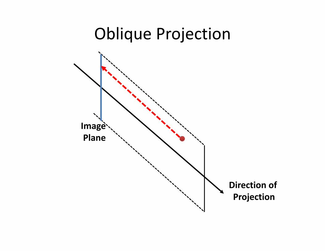
Oblique Projection
Image Plane
Direction of Projection

Properties of Parallel Projection
• Definition: projection directions are parallel.
• Doesn’t look real.
• Can preserve parallel lines
ProjectionProjection
P ll l i 3D P ll l i 2DParallel in 3D Parallel in 2D
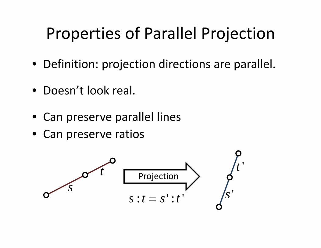
Properties of Parallel Projection
• Definition: projection directions are parallel.
• Doesn’t look real.
• Can preserve parallel lines• Can preserve ratiosp
t t 'Projection
st
s 's : t s ' : t 's : t s : t

Properties of Parallel Projection
• Definition: projection directions are parallel.
• Doesn’t look real.
• Can preserve parallel lines• Can preserve ratiosp• CANNOT preserve angles
Projection

Properties of Parallel Projection
• Definition: projection directions are parallel.
• Doesn’t look real.
• Can preserve parallel lines• Can preserve ratiosp• CANNOT preserve angles
• Often used in CAD, architecture drawings, when images can be used for measurement.when images can be used for measurement.

Properties of Parallel Projection
• No foreshortening
Image PlaneImage Plane

Perspective Projection
• Perspective projection has foreshortening:
Center of Projection
Image Plane

Perspective Projection• Images are mapped onto the image plane in different ways:different ways:
An imageAn image(640*640)
Center of Projection
Image Plane
Projection
Image Plane

Perspective Projection• Images are mapped onto the image plane in different ways:different ways:
An imageAn image(640*640)
Center of Projection
Image Plane
Projection
Image Plane

Perspective Projection• Angle of view tells us the mapping from the image to the image plane:image to the image plane:
Angle of viewField of view
Center of Projection
Image Plane
Projection
Image Plane

Perspective Projection• Not everything will be displayed.
Frustum
Center of Projection
Image Plane
j
Near Plane Far Plane

Perspective Projection• The frustum of perspective projection looks like:like:
Center of Projection
Image Plane
Near PlaneNear Plane

Ortho Projection• What’s the frustum of orthographic projection?
Image Plane
Near FarNear Far

Homogenous Coordinates
• In general, the homogeneous coordinate system is define as:is define as:
wxwy
xy
I h wz
w
z1
In 3DIn homogeneousspace
• For example,
2
4
214
428
0.5 1

Homogenous Coordinates
• Both homogenous vectors and matrices are l blscalable:
wxwy
xy
y
wzw
yz1
wm00 wm01 wm02 wm03
wm10 wm11 wm12 wm13
m00 m01 m02 m03
m10 m11 m12 m13
10 11 12 13
wm20 wm21 wm22 wm23
wm30 wm31 wm32 wm33
10 11 12 13
m20 m21 m22 m23
m30 m31 m32 m33

Perspective Projection• Derivation:
x ' xyz
xy 'd1
1
1
Z Axis d
Image PlaneImage PlaneXY Plane

Perspective Projection• Derivation:
xd / z xyz
xd / zyd / zd1
1
1
Z Axis d
Image PlaneImage PlaneXY Plane

Perspective Matrix• Derivation:
x
xd / z
xyz
xd / zyd / zd
How?
1
d1
How?
xd / zyd / z
dd
xy
y
d1
dd1
yz1
The z axis now becomes useless…

OpenGL Perspective Matrix• In practice, OpenGL uses the z axis for depth test Its matrix looks like this:test. Its matrix looks like this:
d
x
x / z
dd
a b
yz
y / za b / z
1 1
1
The depth value now can be used for depth testThe depth value now can be used for depth test.We will discuss this in more details later...

Vanishing Point• Given a ray:
px
p tn x
py
pz
1
nx
ny
px tnx
py tny
pz tnz
1 nz
1
1
• Its projection: d(px tnx )
d px tnx
d
px tnx
d(py tny )
...(p tn )
dd
a b1
x x
py tny
pz tnz
1
d x x
pz tnz
dpy tny
p tn
(pz tnz ) 1 1 pz tnz

Vanishing Point• When t goes to infinity:
p tn n Parallel lines meet ath i hi i
limt
dpx tnx
pz tnz
dpy tny
dnx
nz
dny
the vanishing point.
• What if there is another ray:
dpz tnz
d
nz
y
qx tnx
q tn
qy tny
qz tnz
1
1

Properties of Perspective Projection
• Lines are mapped to lines.P ll l li t i ll l I t d• Parallel lines may not remain parallel. Instead, they may meet at the vanishing point.
• Ratios are not preserved• Ratios are not preserved.
• It has foreshortening effects. So it looks real.
• Distances cannot be directly measured, as in parallel projectionparallel projection.

Basic OpenGL Projection• Everything will be considered in the eye space:
• Geometry objects have been transformed into the eye y j ycoordinate system using the GL_MODELVIEW matrix.
• You define the projection matrix in GL_PROJECTION, also in the eye space.in the eye space.
• OpenGL always assume that the viewing direction is the –z direction.
• OpenGL automatically processes each vertex using GL_PROJECTION:
Aft j ti th f t i t d i t• After projection, the frustum is converted into a canonical view volume ( [‐1, 1] in all coordinates)

OpenGL Orthographic Projection
glOrtho(left,�right,�bottom,�top,�near,�far)X range Y range Z range
(right, top, far)(right, top, far)
(1, 1, 1)( , , )
(left, bottom, near) (‐1, ‐1, ‐1)

OpenGL Orthographic Projection
glOrtho(l,�r,�b,�t,�n,�f)
• Translation so that the center is the origin.• Scaling so that the size becomes (2 2 2)Scaling so that the size becomes (2, 2, 2).
l 2 2 r l 1
r l2
1 t b
2
2r l
2t b
2r l
r lr l
2t b
t bt b
2
1 f n
21
t b2
f n1
t b t b2
f n
f nf n1
1 1 1

OpenGL Perspective ProjectionglFrustum(left,�right,�bottom,�top,�near,�far)
Always positive
(left, right, bottom, top)may not be centered along
Always positive,although it’s facingthe –z direction
Frustum
y gthe axis
Center of ProjectionProjection
Near Plane(Image Plane) Far Plane

OpenGL Perspective ProjectiongluPerspective(fov,�aspect_ratio,�near,�far)
Always positive
ratio=image_width/image_height
Always positive,although it’s facingthe –z direction
Frustumf
top: near*ctan(fov/2)right: near*ratio*ctan(fov/2)
Center of Projection
fov
Projection
Near Plane(Image Plane) Far Plane

OpenGL Perspective Projection
glFrustum(…) is less useful than gluPerspective(...).glFrustum(…) is less useful than gluPerspective(...).
But we can still use it for ut we can still use it fordemonstration purpose next.

OpenGL Perspective Projection
ProjectionProjection
xd / z
n
x
yd / z
n
nn
n
yz
1
1 1

OpenGL Perspective Projection
Projection
xd / zyd / z
nn
xy
in (‐1, 1)yd / z
a b / z1
na b1
yz1
1 1 in (‐n, ‐f), why???

OpenGL Perspective Projection
a b / (n) 1 (z n)
xd / z
a b / ( n) 1 (z n)a b / ( f ) 1 (z f )
yd / za b / z
a
f n1
a
f n
b 2 fn
b f n

OpenGL Perspective Projection
Projection
(r/n, t/n, 1)
Projection
(l/n, b/n, ‐1)
11
x
1
f nf n
2 fnf n
yz
f n f n
1
1

OpenGL Perspective Projection
(r/n, t/n, 1) (1, 1, 1)
Transform
(l/n, b/n, ‐1) (‐1, ‐1, ‐1)
2nr l
2n
1r l2n
t b
2nr l
r lr l
2n t b
2n
t b1
1
1t b2n
11
2nt b
t bt b
11
1 1 1
TranslationScaling

OpenGL Perspective Projection
(1, 1, 1)
Projection
(‐1, ‐1, ‐1)
2nr l
r lr l
2 t b
11
2nr l
r lr l
2n t b
2n
t bt bt b
11
f nf n
2 fnf n
1
t b t b
f nf n
2 fnf n
1
1
Original ProjectionTransformation

What happens after projection?• Clipping
• Viewport transformation
clipping
• Viewport transformation(1, 1)
viewport
(800, 800)
• Rasterization(‐1, ‐1)
viewport
(0, 0)
rasterizerasterize

Depth Test• Before rasterization, all processes are done based on vertices.on vertices.
• The z coordinate at each vertex is transformed into a new z value (or called the depth value)a new z value (or called the depth value).
• During rasterization, the z value of each pixel is i t l t d f tiinterpolated from vertices.
• The z value then stored in the depth buffer for• The z value then stored in the depth buffer, for occlusion tests. (smaller z means closer).

Depth Test
• The depth buffer is part of the frame buffer:
bl d bl h d h b ff
glutInitDisplayMode(GLUT_DOUBLE|GLUT_RGB|GLUT_DEPTH);
• To enable or disable the depth buffer:glEnable(GL_DEPTH_TEST);
• Without the depth test the occlusion is
glDisable(GL_DEPTH_TEST);
Without the depth test, the occlusion is determined by the drawing order.

Common Issues
• When you set up the perspective matrix:• Near cannot be zero!• far/near cannot be too large! (far cannot be / g (too large, or near cannot be too small.) Why?
2n r l 2nr l
r lr l
2n t b
t b t b
f nf
2 fnf
f n f n
1