vigil 3 amplifiers - baldwin boxall · vigil 3 amplifiers installation instructions vigil 3...
TRANSCRIPT
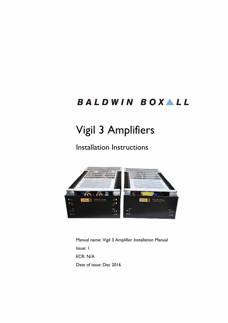
Vigil 3 Amplifiers
Installation Instructions
Manual name: Vigil 3 Amplifier Installation Manual
Issue: 1
ECR: N/A
Date of issue: Dec 2016

Vigil 3 Amplifiers
Installation Instructions
ii Vigil 3 Amplifier Installation Manual issue 1
© Dec 2016 Baldwin Boxall Communications Limited
Wealden Industrial Estate
Farningham Road, Jarvis Brook
Crowborough
East Sussex
TN6 2JR
UK
Telephone: +44 (0)1892 664422
Facsimile: +44 (0)1892 663146
Email: [email protected]
Website: http://www.baldwinboxall.co.uk
This equipment has been designed and manufactured to conform to the following EC Standards:
EMC: EN55103-1 Environment Classification: E1,
EMC: EN55103-2 Environment Classification: E5,
Safety: EN60065
Failure to use the equipment in the manner described in the product literature will invalidate the conformity.
A “Declaration of Conformity” statement to the above standards and a list of auxiliary equipment used for compliance verification is available on request.

Vigil 3 Amplifiers
Installation Instructions
Vigil 3 Amplifier Installation Manual issue 1 iii
Amendment Record ___________________________________v
Proprietary Notice ____________________________________ v
Safety Information ___________________________________ vi
Comments_________________________________________ vi
Introduction
Vigil 3 Amplifier Description _____________________________1
Vigil 3 Amplifier Specifications ____________________________3
Installation Examples
Example 1: A-B Dual Circuit _____________________________6
Example 2: Paralleled Outputs for Higher Power ______________7
Basic Fault Finding
“OK / Fault” LED flashing or not illuminated _________________9
Disassembly Procedures _______________________________10
Maintenance
Maintenance Requirements of BS5839-8 ___________________13
Vigil 3 Amplifiers Routine Maintenance ____________________13

Vigil 3 Amplifiers
Installation Instructions
iv Vigil 3 Amplifier Installation Manual issue 1

Vigil 3 Amplifiers
Installation Instructions
Vigil 3 Amplifier Installation Manual issue 1 v
AMENDMENT RECORD
PROPRIETARY NOTICE
All data and information contained within this manual is of a proprietary nature with the exclusive title to the same held by Baldwin Boxall Communications Limited. The possession of this manual and the use of the information is, therefore, restricted only to those persons duly authorised by Baldwin Boxall Communications Limited.
Do not reproduce, transcribe, store in a retrieval system or translate into any language, any part of this manual without the prior permission of Baldwin Boxall Communications Limited.
In the interest of continual product development, Baldwin Boxall Communications Limited reserves the right to make changes to product specification without notice or liability. Use of Baldwin Boxall Communications Limited products as critical components in life support systems is not authorised except with express written approval from Baldwin Boxall Communications Limited.
Change Note
Number
Nature of Amendment Date of
Amendment
DP347 Initial release: Issue 1 Dec 2016

Vigil 3 Amplifiers
Installation Instructions
vi Vigil 3 Amplifier Installation Manual issue 1
SAFETY INFORMATION
Personnel who install, maintain or repair this equipment must read the safety information below before starting work.
Voltages in excess of 30 Volts RMS or 50 Volts DC are considered Hazardous and in certain circumstances can be lethal.
If Functional Testing, Maintenance, or Repair is to be completed with the Mains Power (and/or battery backup) connected then this should only be undertaken by personnel who are fully aware of the danger involved and who have taken adequate precautions and training.
This Manual contains Warnings, Cautions and Notes.
Warnings describe potential threats to health or life, e.g.
Cautions describe potential threats to the equipment, e.g.
Notes are statements that are useful to the user in the context of a particular section of the manual, e.g.
COMMENTS
Comments regarding the content of this manual are welcome and should be addressed to [email protected].
!
WARNING
Before attempting to remove this component, ensure the Mains
Power Supply and Battery Backup have been disconnected.
CAUTION
Notice must be taken of all cautions.
If a Caution is ignored the equipment may be damaged.
CAUTION: ELECTRO-STATIC SENSITIVE DEVICES
Observe the relevant precautions for the protection of Electro-
static Sensitive Devices when handling this equipment.
NOTE: Do not speak into the microphone until the "Speak Now" LED is
illuminated.

Vigil 3 Amplifier
Installation Instructions
Vigil 3 Amplifier Installation Manual issue 1 1
1 Introduction
1.1 VIGIL 3 AMPLIFIER DESCRIPTION
The Vigil 3 Amplifier range consists of modules containing 2 or 4 amplifier blocks.
The following Vigil 3 amplifier modules are available;
• BV75D - 2 x 75W Amplifier Blocks
• BV150D -2 x 150W Amplifier Blocks
• BV300D - 2 x 300W Amplifier Blocks
• BV75Q - 4 x 75W Amplifier Blocks
• BV150Q - 4 x 150W Amplifier Blocks
Vigil 3 Amplifiers contain a built in mains PSU and when combined with a BVMBC Battery Charger Module form a complete EN54-4 compliant Battery Backed power supply system.
The audio input for each amplifier is presented on two separate RJ45 connectors.
Each amplifiers output is presented on a single 2-way plug/cage clamp termination connectors providing 100V output.
Vigil 3 Amplifier
Installation Instructions
2 Vigil 3 Amplifier Installation Manual issue 1
The Amplifier Module Mains Input is presented on a standard IEC connection and the 24V DC input (battery connection) is presented on a two 2-way plug/cage clamp termination.
In addition there is a single RJ45 AUX Output for connection to the BVMBC battery charger module.
The power output stage of the amplifier is protected against overload conditions (i.e. short circuits or abnormal loads). Should an amplifier be subjected to an abnormal load the input to the relevant power amplifier is attenuated to a safe level. The amplifier output voltages are also sensed and should they exceed 100V the relevant input signal will be attenuated ensuring safe operation without creating unnecessary distortion.
Over temperature protection is provided using sensors attached to the module heat sink. Should the temperature exceed 70C an Over Temperature fault is indicated and if it exceeds 75C the input signal to the relevant amplifier will be attenuated to a safe level.
If the system is under surveillance it will cause the surveillance detector to indicate a fault condition due to the gain reduction.
Each amplifier block has status LED’s on the front panel consisting of an OK/FAULT LED and a 10%/100% LED.
The OK/FAULT LED indicates the following;
• Steady Green - OK
• Flashing Green - PSU Fault, no 24V or mains present
• Yellow - Overload or Over Temperature Fault
The 10%/100% LED indicates the following;
• Off - No signal output
• Green - 10V signal output
• Yellow - 100V signal output

Vigil 3 Amplifier
Installation Instructions
Vigil 3 Amplifier Installation Manual issue 1 3
1.2 VIGIL 3 AMPLIFIER SPECIFICATIONS
Table 1.1 — Vigil 3 Amplifier Specifications
AMPLIFIERS BV300D
2 x 300W
BV150D
2 x 150W
BV150Q
4 x 150W
BV75D
2 x 75W
BV75Q
4 x 75W
1KHz rated O/P power,
<0.2% THD
300W @
33.3 Ohms 150W @ 66.6 Ohms 75W @ 132 Ohms
Output regulationBetter than
0.5dB Better than 0.3dB Better than 0.2dB
Output voltage obtainable 100V only
Frequency response (-3dB) 35Hz to 20kHz
Input sensitivity and
impedance 0dBm @ 10K Ohms Balanced
Input common mode
rejection ratio (50Hz-20kHz) better than 40dB (typically 60dB)
O/P noise reference to
rated O/P
Better than
85dB(A) Better than 80dB(A)
Cross talk between amps at
1kHz Better than 70dB
Supply voltage (batteries) 22-28V DC
Standby current (batteries) 50mA per amplifier
Rated output power 14A / Amp 7.5A / Amp 3.75A / Amp
Output stage protection
Thermal
Load
Action
Output stage above 90°C
Excessive output stage current
Reduces input to safe level using low distortion VCA
Fuse Protection
AC supply (5 x 20mm) 2 x 2A(T) 1 x 2A(T) 2 x 2A(T) 1 x 2A(T) 2 x 2A(T)
Battery (automotive blade) 2 x 20A 1 x 20A 2 x 20A 1 x 20A 2 x 20A
Terminations
Speaker Line O/P 2 x cage clamp4 x 2 cage
clamp
2 x cage
clamp
4 x 2 cage
clamp
Balanced line inputs RJ45 connections
DC supply (batteries) 2 pin rising clamp
Mains supply input IEC 6A filtered connector
Dimensions 142 mm W x 75 mm H x 311 mm D
Weight 3.1 kg 2.3kg 3.1kg 2.3kg 3.1kg
Mains Supply 230 V +10%/-15% 50/60Hz
Standby Power
Consumption (Mains) 16W 8W 16W 8W 16W
AUX DC O/P @ 30V 5A 2.5A 5A 2.5A 5A
Max Power Consumption 700W 350W 700W 175W 350W

Vigil 3 Amplifier
Installation Instructions
4 Vigil 3 Amplifier Installation Manual issue 1
Vigil 3 Amplifiers
Installation Instructions
Vigil 3 Amplifier Installation Manual issue 1 5
2 Installation Examples
The Vigil 3 Amplifiers have been designed for quick and simple connection and configuration.
The individual amplifier blocks can either be used as independent amplifiers, can be one of two amplifiers wired as an A-B Dual Circuit using a single input signal, or the 300W amplifiers can be paralleled with other 300W Vigil 3 Amplifiers to enable higher power outputs (up to a maximum of 4 Vigil 3 300W amplifiers giving a total of 1200W).
The amplifier blocks have two paralleled input connectors to enable simple interconnection using standard RJ45 patch leads.
The 100V Line output connectors are “cage clamp” type as this type of connector is more reliable than screw terminals.
NOTE: Where possible when A-B circuits are used it is recommended that
A and B circuits are connected to amplifiers in serperate modules. This is
due to power supplies, mains connections and battery connections being
shared by amplifiers inside a module.
NOTE: Where possible when reserve amplifiers are used it is recommended
that reserve amplifiers should be located in a different amplifier module
to the primary amplifier. This is due to power supplies, mains connections
and battery connections being shared by amplifiers inside a module.

Vigil 3 Amplifiers
Installation Instructions
6 Vigil 3 Amplifier Installation Manual issue 1
In order to use the Vigil 3 amplifiers with a BVMBC battery charger module the AUX output connection of up to 5 amplifier modules must be connected to the BVMBC. For more information please see the BVMBC installation manual.
2.1 EXAMPLE 1: A-B DUAL CIRCUIT
Figure 2.1 — Both Amplifiers use the same Input Signal

Vigil 3 Amplifiers
Installation Instructions
Vigil 3 Amplifier Installation Manual issue 1 7
2.2 EXAMPLE 2: PARALLELED OUTPUTS FOR
HIGHER POWER
Figure 2.2 — Connection Details & Settings for Paralleled Amplifiers
NOTE: A maximum of 4 300W amplifier modules can be paralleled
togetther (i.e. 2 x BV300D). Only parallel 300W modules.
NOTE: It is not recommended to use paralleled amplifiers in Voice Alarm
Systems, consider lower power A-B circuits instead.

Vigil 3 Amplifiers
Installation Instructions
8 Vigil 3 Amplifier Installation Manual issue 1

Vigil 3 Amplifiers
Installation Instructions
Vigil 3 Amplifier Installation Manual issue 1 9
3 Basic Fault Finding
The Vigil 3 Amplifiers front panels provide indicators to show the current status of the unit. The following sections provide basic Fault Finding information should these indicators show a fault condition.
3.1 “OK / FAULT” LED FLASHING OR NOT
ILLUMINATED
The OK/FAULT LED should be permanently illuminated green to show the mains and 24V DC supplies are present.

Vigil 3 Amplifiers
Installation Instructions
10 Vigil 3 Amplifier Installation Manual issue 1
Should the OK/FAULT not be permanently illuminated green please refer to Table 3.1 for fault finding information
Table 3.1 — Fault Finding
3.2 DISASSEMBLY PROCEDURES
There are no Disassembly Procedures for this unit.
OK/FAULT LED Status Fault Check
Off No Power Present (24V or
Mains)
Battery Connection
Battery Voltage
Battery Fuses
Mains Connection
Mains Fuses / Circuit
Breakers
Flashing 24V or Mains Supply Failed Remove 24V supply if LED
extinguishes then fault is with
mains supply. Check mains
supply as above.
Remove Mains Supply if LED
extinguishes then fault is with
24V supply. Check battery
connections as above.
If both Mains Supply and 24V
supply are present at the
amplifier module then it has
failed and must be returned
for service.
Yellow Overload or
Overtemperature Fault
Disconnect speaker lines, if
LED returns to Green then
either the speaker lines are
overloaded or shorted
Disconnect speaker lines, if
LED remains yellow then an
overtemperature fault has
occured. Allow amplifier
module to cool and check
cooling fans.
!
WARNING
The Vigil 3 Amplifiers output stages contain Hot Parts, High
Voltages, and operate at High Frequencies.
Do not attempt to disassemble these units or operate them
without the covers in place.

Vigil 3 Amplifiers
Installation Instructions
Vigil 3 Amplifier Installation Manual issue 1 11
CAUTION
There are no user replaceable fuses inside the Vigil 3 amplifiers.
Failed units should be returned to Baldwin Boxall for repair or
replacement.

Vigil 3 Amplifiers
Installation Instructions
12 Vigil 3 Amplifier Installation Manual issue 1

Vigil 3 Amplifiers
Installation Instructions
Vigil 3 Amplifier Installation Manual issue 1 13
4 Maintenance
4.1 MAINTENANCE REQUIREMENTS OF
BS5839-8
When a Vigil 3 Amplifiers is installed in a Voice Alarm System then the system must be maintained according to the requirements of BS5839-8.
4.2 VIGIL 3 AMPLIFIERS ROUTINE
MAINTENANCE
The Vigil 3 Amplifiers amplifier module requires a minimum of routine maintenance.
If the unit is operated in a particularly dusty environment, it may be necessary to occasionally remove accumulated dust from the external heatsink using a vacuum cleaner or similar.
