vigilohmifl12h - productinfo.schneider-electric.com... · vigilohmifl12h insulationfaultlocator...
TRANSCRIPT

Vigilohm IFL12H
Insulation Fault Locator
User manual7EN02-0407-0209/2019
www.schneider-electric.com
Legal InformationThe Schneider Electric brand and any trademarks of Schneider Electric SE and itssubsidiaries referred to in this guide are the property of Schneider Electric SE or itssubsidiaries. All other brands may be trademarks of their respective owners.
This guide and its content are protected under applicable copyright laws andfurnished for informational use only. No part of this guide may be reproduced ortransmitted in any form or by any means (electronic, mechanical, photocopying,recording, or otherwise), for any purpose, without the prior written permission ofSchneider Electric.
Schneider Electric does not grant any right or license for commercial use of the guideor its content, except for a non-exclusive and personal license to consult it on an "asis" basis. Schneider Electric products and equipment should be installed, operated,serviced, and maintained only by qualified personnel.
As standards, specifications, and designs change from time to time, informationcontained in this guide may be subject to change without notice.
To the extent permitted by applicable law, no responsibility or liability is assumed bySchneider Electric and its subsidiaries for any errors or omissions in the informationalcontent of this material or consequences arising out of or resulting from the use of theinformation contained herein.

Insulation Fault Locator
Safety informationImportant information
Read these instructions carefully and look at the equipment to become familiarwith the device before trying to install, operate, service, or maintain it. Thefollowing special messages may appear throughout this manual or on theequipment to warn of potential hazards or to call attention to information thatclarifies or simplifies a procedure.
The addition of either symbol to a “Danger” or “Warning” safety label indicatesthat an electrical hazard exists which will result in personal injury if theinstructions are not followed.
This is the safety alert symbol. It is used to alert you to potential personal injuryhazards. Obey all safety messages that accompany this symbol to avoid possibleinjury or death.
DANGERDANGER indicates a hazardous situation which, if not avoided, will result indeath or serious injury.
Failure to follow these instructions will result in death or serious injury.
WARNINGWARNING indicates a hazardous situation which, if not avoided, could resultin death or serious injury.
CAUTIONCAUTION indicates a hazardous situation which, if not avoided, could result inminor or moderate injury.
NOTICENOTICE is used to address practices not related to physical injury.
Please note
Electrical equipment should be installed, operated, serviced and maintained onlyby qualified personnel. No responsibility is assumed by Schneider Electric for anyconsequences arising out of the use of this material. A qualified person is one whohas skills and knowledge related to the construction, installation, and operation ofelectrical equipment and has received safety training to recognize and avoid thehazards involved.
7EN02-0407-02 3

Insulation Fault Locator
NoticeFCC
This equipment has been tested and found to comply with the limits for a Class Adigital device, pursuant to Part 15 of the FCC rules. These limits are designed toprovide reasonable protection against harmful interference when the equipment isoperated in a commercial environment. This equipment generates, uses, and canradiate radio frequency energy and, if not installed and used in accordance withthe instruction manual, may cause harmful interference to radio communications.Operation of this equipment in a residential area is likely to cause harmfulinterference in which case the user will be required to correct the interference athis own expense.
The user is cautioned that any changes or modifications not expressly approvedby Schneider Electric could void the user’s authority to operate the equipment.
This digital apparatus complies with CAN ICES-3 (A) /NMB-3(A).
4 7EN02-0407-02

Insulation Fault Locator
About this manualThis manual discusses features of the Vigilohm IFL12H insulation fault locator andprovides installation, commissioning, and configuration instructions.
This manual is intended for use by designers, panel builders, installers, systemintegrators, and maintenance technicians who are related with ungroundedelectrical distribution systems featuring insulation monitoring devices (IMDs) withfault locating devices for medical applications.
Throughout the manual, the term “device” refers to IFL12H. Throughout themanual, the term “IMD” refers to IM20-H.
This manual assumes you have an understanding of insulation monitoring andlocating and are familiar with the equipment and power system in which yourdevice is installed.
This manual does not provide instructions on how to incorporate device data orperform device configuration using energy management systems or software.
Please contact your local Schneider Electric representative to learn whatadditional training opportunities are available for your devices.
Make sure you are using the most up-to-date version of your device’s firmware inorder to access the latest features.
The most up-to-date documentation about your device is available for downloadfrom www.schneider-electric.com.
Related documents
Document Number
Instruction Sheet: Vigilohm IFL12H InsulationFault Locator
QGH34270
Vigilohm Catalog PLSED310020EN
The ITearthing system: a solution to improveindustrial electrical network availability -Application guide
PLSED110006EN
System earthings in LV (The schematics of earthlinks in LV (neutral modes) Cahier technique n°172 )
CT172
The ITsystem earthing (unearthed neutral) in LV(The ITscheme (in isolated neutral) of the linksto the earth in LV Cahier technique n° 178)
CT178
Secure power distribution and monitoringsolution for operating theatres - Solution guide
DESWED109024EN
7EN02-0407-02 5


Insulation Fault Locator
Table of Contents
Safety precautions ......................................................................................9Introduction ................................................................................................10
Ungrounded power system overview..........................................................10Insulation resistance (R) monitoring ...........................................................10Device overview .......................................................................................10Supplemental information.......................................................................... 11Hardware overview................................................................................... 11Accessories .............................................................................................12Device configuration and analysis tools ......................................................12
Application .................................................................................................14Example application: Locating the insulating alarm with IMD........................14Example application: Locating the insulating alarm with IMD, wheredevice and IMD are connected to an external network .................................14Example application: Locating the insulating alarm with IMD, wheredevice and IMD are connected to communication network ...........................15
Human Machine Interface (HMI) ............................................................17Device menu ............................................................................................17Display interface.......................................................................................17Navigation buttons and icons.....................................................................18Information icons ......................................................................................18Status screens .........................................................................................19Parameter modification using the display....................................................21
Function......................................................................................................23Commissioning ........................................................................................23
Automatic commissioning ....................................................................24Manual commissioning........................................................................24Checking wiring connection .................................................................25
General configuration................................................................................26Clock .................................................................................................26Password ...........................................................................................26Language...........................................................................................26Identification.......................................................................................27Display...............................................................................................27
Network configuration ...............................................................................27Channel Name ...................................................................................27
Alarm configuration...................................................................................28Insulation alarm (Ins. Alarm) thresholds ................................................29
I/O configuration .......................................................................................30Insulation alarm relay (Ins. Al. Relay)....................................................30
R measurement........................................................................................31Insulation measurements ....................................................................31
Monitoring power system insulation ...........................................................31Insulation fault log.....................................................................................31Reset.......................................................................................................32Auto-test ..................................................................................................33
Communication .........................................................................................35Communication parameters ......................................................................35
7EN02-0407-02 7

Insulation Fault Locator
Modbus functions .....................................................................................35Modbus register table format .....................................................................36Modbus registers table..............................................................................36Alarm event records..................................................................................43Date and time (TI081 format) .....................................................................45
Maintenance ..............................................................................................47Product status light indicator......................................................................47Troubleshooting .......................................................................................47
Specifications ............................................................................................49
8 7EN02-0407-02

Safety precautions Insulation Fault Locator
Safety precautionsInstallation, wiring, testing and service must be performed in accordance with alllocal and national electrical codes.
Safety measures
DANGERHAZARD OF ELECTRIC SHOCK, EXPLOSION, OR ARC FLASH• Apply appropriate personal protective equipment (PPE) and follow safe
electrical work practices. See NFPA 70E in the USA, CSA Z462 orapplicable local standards.
• Turn off all power supplying this device and the equipment in which it isinstalled before working on the device or equipment.
• Always use a properly rated voltage sensing device to confirm that all poweris off.
• Treat communications and I/O wiring connected to multiple devices ashazardous live until determined otherwise.
• Do not exceed the device’s ratings for maximum limits.• Disconnect all the device’s input and output wires before performing
dielectric (hi-pot) or Megger testing.• Never shunt an external fuse or circuit breaker.• Ensure that your ungrounded system has a compatible insulation monitoring
device.Failure to follow these instructions will result in death or serious injury.
NOTE: See IEC 60950-1:2005, Annex W for more information oncommunications and I/O wiring connected to multiple devices. See IEC60364-4-41 for more information on protection against electrical shock.
WARNINGUNINTENDED OPERATION
Do not use this device for critical control or protection applications where humanor equipment safety relies on the operation of the control circuit.
Failure to follow these instructions can result in death, serious injury, orequipment damage.
NOTICEEQUIPMENT DAMAGE• Do not open the device case.• Do not attempt to repair any components of the device.Failure to follow these instructions can result in equipment damage.
7EN02-0407-02 9

Insulation Fault Locator Introduction
Introduction
Ungrounded power system overviewUngrounded power system is an earthing system, which increases continuity ofservice of power systems and protection of people and property.
This system varies from country to country, including some applications where thissystem is mandated, such as hospital and the naval applications. This system istypically used in instances where the unavailability of power could result in lostproduction or incur significant downtime costs. Other potential applications arewhen there is a need to minimize the risk of fire and explosion. Lastly, this systemis chosen in certain cases because it can facilitate preventive and correctivemaintenance operations.
The system transformer’s neutral is isolated from earth, or there is a highimpedance between the neutral and earth, while the electrical load frames areearthed. This isolates the transformer and the load such that if the first fault occursthere is no loop for shorting current to flow, allowing the system to continue tooperate normally without hazard to people and equipment. This system must havevery low network capacitance to ensure that the first fault current cannot generatesignificant voltage. However, the faulty circuit must be detected and repairedbefore a second fault occurs. Because this system can tolerate an initial fault,maintenance operations can be improved and carried out in a safe and convenientmanner.
Insulation resistance (R) monitoringUngrounded power system require insulation monitoring to identify when the firstinsulation fault has occurred.
In ungrounded power system, the installation must either be ungrounded or mustbe grounded using a sufficiently high level of impedance.
In the event of only one ground or earth fault, the fault current is very low andinterruption is unnecessary. However, given that a second fault could potentiallycause the circuit breaker to trip, an IMD has to be installed to indicate an initialfault. The device installed along with IMD detects the initial fault on the particularchannel where the fault occurred. This device must trigger an audible and/or avisual signal.
By constantly monitoring the insulation resistance, you can keep track of thesystem quality, which is a form of preventive maintenance. Further, monitoring theinsulation resistance of individual channels, you can keep track of the individualchannel quality.
Device overviewThe device is a digital insulation fault locator (IFL) for low-voltage ungroundedpower systems. An insulation monitoring device (IMD) must be connected to theungrounded system where the device is connected. The device along with IMDlocates the first fault and signals fault as alarm.
IMD monitors the insulation resistance of the system by injecting a signal. Thistechnique is used for all power system types - AC, DC, combined, rectified, with avariable speed drive, etc. The device is connected to the channels of the systemusing Toroid. The device uses the injected signal from the IMD to monitor theindividual channel circuits’ insulation resistance. The device alerts when one ormore of the monitored channels resistance is lower than the defined threshold andidentifies the faulty channels. The device also provides local channel resistancevalues, which is used for more precise monitoring of individual channels within thesystem for the purposes of preventative maintenance.
10 7EN02-0407-02

Introduction Insulation Fault Locator
The device offers the following features:• Fault location up to 12 channels• Fast fault location (time < 5 s)• Dedicated commissioning mode for quick installation verification• Auto-detects and configures compatible toroids in commissioning mode• Detection of insulation faults in accordance to the configured threshold• Relay for fault indication• Communication via Modbus RS-485 protocol• Configurable channel name• Configurable insulation threshold per channel• Insulation resistance display (R)• Insulation fault log
Supplemental informationThis document is intended to be used in conjunction with the installation sheet thatships in the box with your device and accessories.
See your device’s installation sheet for information related to installation.
See your product’s catalog pages at www.schneider-electric.com for informationabout your device, its options and accessories.
You can download updated documentation from www.schneider-electric.com orcontact your local Schneider Electric representative for the latest informationabout your product.
Hardware overviewVigilohm IFL12H feature 5 terminal blocks.
A Alarm relay
B Auxiliary power supply
C Product status LED
D Communication LED
E Menu button
F No alarm LED
G Esc button
H Alarm LED
I 3 contextual menu buttons
J LabelNOTE: Scan the QR code toview the device documentation:QR code link
K RS-485 communication
L 12 toroid connections
M Voltage input
N LCD screen
O Gasket
P Commercial reference andmanufacturing data
7EN02-0407-02 11

Insulation Fault Locator Introduction
Q Specification LabelNOTE: Scan the QR code toview the device documentation:QR code link
R DIN mounting clip
Device commercial reference
Model Commercial reference
IFL12H IMDIFL12H
AccessoriesAccessories are required depending on the type of installation on which the deviceis installed.
Accessories list
Accessory Catalog number
Toroid Refer Vigilohm catalog
Toroids
The toroids are used to connect the device to the channels of the system, whichcan be monitored. The compatible toroids are:• TA30
NOTE: This toroid is advised for IFL12H.• PA50• IA80• MA120• SA200• GA300• TOA80• TOA120Refer to the Vigilohm catalog for the most up to date listing of compatible devices.Refer to the toroid user guide for specifications.
Device configuration and analysis tools
ION Setup
ION Setup is a device configuration and verification tool.
ION Setup communicates with the device on the network and provides the basicconfiguration, which can be done via HMI and also advanced configuration, suchas firmware upgrade and other features.
See ION Setup for latest version and instruction to install the tool and to add yourdevice.
12 7EN02-0407-02

Introduction Insulation Fault Locator
Ecoreach
Ecoreach is a software solution to configure and commission the smart device.
Ecoreach communicates with the device on the network and provides thefollowing features:• Automatic device discovery• Device Check up & Control• Firwmare upgradeSee Ecoreach for instruction to install the solution and to add your device.
Power Monitoring Expert
EcoStruxure™ Power Monitoring Expert is a complete supervisory softwarepackage for power management applications.
The software collects and organizes data gathered from your facility’s electricalnetwork and presents it as meaningful, actionable information via an intuitive webinterface.
Power Monitoring Expert communicates with devices on the network to provide:• Real-time monitoring through a multi-user web portal• Trend graphing and aggregation• Power quality analysis and compliance monitoring• Preconfigured and custom reportingSee the EcoStruxure™ Power Monitoring Expert online help for instructions onhow to add your device into its system for data collection and analysis.
Power SCADA Operation
EcoStruxure™ Power SCADA Operation is a complete real-time monitoring andcontrol solution for large facility and critical infrastructure operations.
It communicates with your device for data acquisition and real-time control. Youcan use Power SCADA Operation for:• System supervision• Real-time and historical trending, event logging• PC-based custom alarmsSee the EcoStruxure™ Power SCADA Operation online help for instructions onhow to add your device into its system for data collection and analysis.
Gateways and supervisionThe device is compatible with the gateways and supervision products.
The compatible gateway products are:• Com’X510
See Com’X510 Product Information for more information..• Link150
See Link150 Product Information for more information.The compatible supervision product is spaceLYnk. See spaceLYnK ProductInformation for more information.
7EN02-0407-02 13
Insulation Fault Locator Application
ApplicationThis section explains the following examples of the insulation fault locationapplication for ungrounded power system:• Locating the insulating alarm with IMD• Locating the insulating alarm with IMD, where device and IMD are connected
to an external network• Locating the insulating alarm with IMD, where device and IMD are connected
to communication network
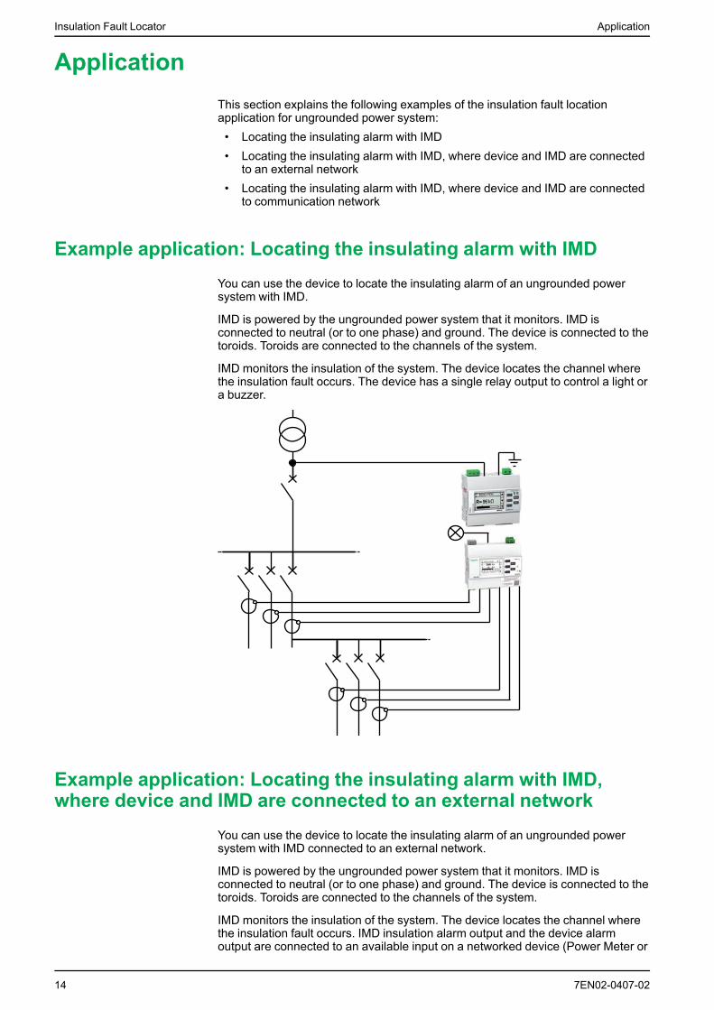
Example application: Locating the insulating alarm with IMDYou can use the device to locate the insulating alarm of an ungrounded powersystem with IMD.
IMD is powered by the ungrounded power system that it monitors. IMD isconnected to neutral (or to one phase) and ground. The device is connected to thetoroids. Toroids are connected to the channels of the system.
IMD monitors the insulation of the system. The device locates the channel wherethe insulation fault occurs. The device has a single relay output to control a light ora buzzer.
Example application: Locating the insulating alarm with IMD,where device and IMD are connected to an external network
You can use the device to locate the insulating alarm of an ungrounded powersystem with IMD connected to an external network.
IMD is powered by the ungrounded power system that it monitors. IMD isconnected to neutral (or to one phase) and ground. The device is connected to thetoroids. Toroids are connected to the channels of the system.
IMD monitors the insulation of the system. The device locates the channel wherethe insulation fault occurs. IMD insulation alarm output and the device alarmoutput are connected to an available input on a networked device (Power Meter or
14 7EN02-0407-02

Application Insulation Fault Locator
PLC, for example). The networked device is connected to a supervisor via acommunication network.
NOTE: In this example, only the fault information is available to the supervisor.
PLC
Modbus
Ethernet Modbus TCP
Example application: Locating the insulating alarm with IMD,where device and IMD are connected to communication network
You can use the device to locate the insulating alarm of an ungrounded powersystem with IMD connected to communication network.
IMD is powered by the ungrounded power system that it monitors. IMD isconnected to neutral (or to one phase) and ground. The device is connected to thetoroids. Toroids are connected to the channels of the system.
IMD monitors the insulation of the system. The device locates the channel wherethe insulation fault occurs. IMD and the device are connected to a supervisor viaModbus communication. This application can support the following actions fromthe supervisor level:• Display:◦ Product status◦ All the channels insulation alarm (active and acknowledged)
• Configuring the product remotely: all the settings can be accessed remotely
7EN02-0407-02 15

Insulation Fault Locator Application
Ethernet Gateway
Modbus
Power Monitoring ExpertPower SCADA OperationEcoreach
Ethernet Modbus TCP
16 7EN02-0407-02

Human Machine Interface (HMI) Insulation Fault Locator
Human Machine Interface (HMI)
Device menuUsing the device’s display, you can navigate through the different menus toperform basic setup on your device.
Monitoring
INSULATIONR
SUMMARYSettings
Ins. Alarm
I/O Config
Password
Language EnglishFrancaisEspañolPусскийChinese ( )ItalianoDeutschPortuguês
Identification IMDIFL12HFirmware versionFirmware release dateCRC App.Serial numberQR code
Ins. Alarm
Network
Ins. Al. Relay
Modbus
Address
Modify password
MENU
Activation
Display
Contrast
Backlight
Date/Time
Baudrate
Parity
Commission
Auto
Manual
Reset
Reset Logs
Factory Reset
Logging
Network
Channel Name
Display interfaceUse the device display to perform various tasks such as configuring the device,displaying status screens, acknowledging alarms, or viewing events.
7EN02-0407-02 17

Insulation Fault Locator Human Machine Interface (HMI)
1 Screen identification area containing a menu icon, and the name of the menu or the parameter
2 Information area displaying information specific to the screen (measurement, insulation alarm,settings)
3 Navigation buttons
Navigation buttons and iconsUse the display buttons to navigate through menus and perform actions.
Legend Button Icon Description
1 Menu – Display the level 1 menu (Menu).
2 Esc – Go back to the previous level.
3 Contextual menu button 3 Scroll up the display or move to the previous item in a list.
Access the date and time setting. If the clock icon flashes, it means thatthe Date/Time parameter needs to be set.
Increase a numerical value.
Modify the selected character
Select all channels to set same value of insulation alarm threshold.
Select all channels to perform manual commission.
Select each channel to set value of insulation alarm threshold.
Select each channel to perform manual commission.
4 Contextual menu button 2 Scroll down the display or move to the next item in a list.
Move one digit to the left within a numerical value. If the digit on the farleft is already selected, pressing the button loops you back to the digiton the right.
Move from one character to the right of the one that is currentlyselected, or to loop back to the character on the left.Move from one channel to another channel to set value of insulationalarm threshold and to select channel for manual commissioning.
5 Contextual menu button 1 Validate the selected item.
Run the auto-test manually.
Go to a menu or submenu, or edit a parameter.
Acknowledge the insulation alarm.
Exit automatic commissioning mode.
Information iconsIcons in the information area of the LCD display provide information such as whatmenu is selected and the insulation alarm status.
18 7EN02-0407-02

Human Machine Interface (HMI) Insulation Fault Locator
Icon Description
Main menu
• System resistance (in the absence of an insulation fault)• Measurement parameters menu• Monitoring menu• System resistance as primary record in Logging page
Fault log menu
Setting parameters menu and submenu
Display language selection menu
Product identification
• Indication of an insulation alarm• Indication of product status• Indication of channel status
Summary
No alarm
Alarm
Toroid disconnect
Date/Time parameters menu
Insulation alarm parameters menu
I/O configuration parameters menu
Modbus parameters menu
Commission parameters menu
Password parameters menu
Display parameters menu
Reset parameters menu
Status screens
Summary
The default screen shows the summary screen. This screen displaysuncommissioned channels, commissioned channels, and insulation status of thecommissioned channels.
An example of all 12 commissioned channels is as follows:
7EN02-0407-02 19

Insulation Fault Locator Human Machine Interface (HMI)
SUMMARY
1 2 3 4 5 6
10 11 12987
An example of 12 commissioned channel and 3 channels (channel number : 2, 6,and 10) displaying insulation alarm is as follows:
SUMMARY
1 2 3 4 5 6
10 11 12987
An example of 12 commissioned channel and 3 channels (channel number : 2, 6,and 10) displaying acknowledged insulation alarm is as follows:
SUMMARY
1 2 3 4 5 6
10 11 12987
Insulation resistance measurement (R)
The device displays the insulation resistance measurement of each individualchannel. An example measurement of channel 4 is as follows:
INSULATION
100R = k
1k 10k 100k 1M 10M100
=
CHANNEL - 4
4
50 k
10
20 7EN02-0407-02

Human Machine Interface (HMI) Insulation Fault Locator
Insulation alarm detected: insulation fault
The device displays the insulation fault screen when the insulation value fallsbelow the insulation alarm threshold. An example of insulation alarm of channel 4is as follows:
INS.ALARM
R =
1k 10k 100k 1M 10M100
=
5004
CHANNEL - 4
50 k
10
Acknowledge the insulation alarm by pressing the button.
Insulation alarm acknowledged
This screen is displayed when you have acknowledged the insulation alarm. Anexample of insulation alarm acknowledged of channel 4 is as follows:
INS.ALARM
1k 10k 100k 1M 10M10010
4
CHANNEL - 4
500R =
= 50 k
Parameter modification using the displayTo modify the values, you must be thoroughly familiar with the interface menustructure and general navigation principles.
For more information about how the menus are structured, see Device menu,page 17.
To modify the value of a parameter, follow either of these two methods:• Select an item (value plus unit) in a list.• Modify a numerical value, digit by digit and character value.For the following parameters, the numerical value can be modified:• Date• Time• Password• Modbus address• Toroid turnsFor Channel Name parameter, the character value can be modified.
7EN02-0407-02 21

Insulation Fault Locator Human Machine Interface (HMI)
Selecting a value in a list
To select a value in a list, use the up and down menu buttons to scroll through the
parameter values until you reach the desired value, then press to confirm thenew parameter value.
Modifying a numerical value
The numerical value of a parameter is made up of digits and the one on the farright is selected by default. To modify a numerical value, use the menu buttons asfollows:
• to modify the selected digit.
• to select the digit to the left of the one that is currently selected, or to loopback to the digit on the right.
• to confirm the new parameter value.
Modifying a character value
The character value of a parameter is made up of character and the one on the farleft is selected by default. To modify a character value, use the menu buttons asfollows:
• to modify the selected character.
• to select the character to the right of the one that is currently selected, orto loop back to the character on the left.
• to confirm the new parameter value.
Saving a parameter
After you have confirmed the modified parameter, one of following two actionsoccur:• If the parameter has been saved correctly, the screen displays Saved and
then returns to the previous display.• If the parameter has not been saved correctly, the screen displays Error and
the editing screen remains active. A value is deemed to be out of range whenit is classed as forbidden or when there are several interdependentparameters.
Canceling an entry
To cancel the current parameter entry, press the Esc button. The previous screenis displayed.
22 7EN02-0407-02

Function Insulation Fault Locator
Function
CommissioningThe device must be commissioned so that the device can detect toroids andidentify the insulation fault in the respective toroids.
Performing commissioning is mandatory when you:• Install a new device• Install one or more toroid to an installed device• Remove one of more toroid from an installed device• Replace the toroid with a different type. (Example: Replace TA30 type by
PA50 type)• Replace the devicePerforming commissioning is not required when you reconnect or replace a toroidwith the same type of toroid.
The device offers the following commissioning modes:• Automatic• Manual
7EN02-0407-02 23

Insulation Fault Locator Function
Automatic commissioning
1. At first power up or factory reset, the device displays Detecting Toroidmessage with a percentage progress bar.
NOTE: At first power up or factory reset, the device performs automaticcommissioning.
• If toroid is detected, the Commissioning screen displays. This screenshows the status of commissioning. The following table provides theinformation of the various displays of commissioning grid.
HMI Display Information
4Commissioned channel 4
4Non-commissioned channel 4
4
Commissioned channel 4 with insulation fault
NOTE: Channel 4 is provided as an example. The displays areapplicable for all 12 channels.NOTE: If you have connected a toroid which is not one of therecommended toroids, then the device should be manuallycommissioned. SeeManual commissioning, page 24. Refer to theVigilohm catalog for the most up to date listing of compatible toroids.
• If toroid is not detected, the No toroidmessage displays. Perform one ofthe following action:◦ Check if the toroid is properly connected and navigate toMenu >
Settings > Commission > Auto. The device performs automaticcommissioning.
◦ The connected toroid is not one of the recommended toroids. Thedevice should be manually commissioned. See Manualcommissioning, page 24.NOTE: Refer to the Vigilohm catalog for the most up to date listing ofcompatible toroids.
2. You can check the wiring of the system. To check, see Checking wiringconnection, page 25. If you do not want to check, ignore this step andcontinue to next step.
3. Press button to exit the commissioning mode.NOTE: The device automatically exits commissioning mode after onehour if manual exit is not performed.
The device displays Summary screen and the clock icon flashes to show thatdate and time needs to be set.
NOTE: If you have connected a new toroid or replaced a toroid, navigatetoMenu > Settings > Commission > Auto. The device performsautomatic commissioning.
Manual commissioning
The device must be manually commissioned if the connected toroid is not one ofthe recommended toroids.
NOTE: Refer to the Vigilohm catalog for the most up to date listing ofcompatible toroids.
24 7EN02-0407-02

Function Insulation Fault Locator
1. Navigate toMenu > Settings > Commissioning > Manual.The Manual screen displays with the channel grid and a flashing dot on thechannel 1 grid. This indicates the channel 1 is selected.
2. Perform any one of the following:
• To commission channel 1, press button.
• To commission other channels, press button to navigate to the
desired channel and press button.
• To commission all channels, press button and press button.The Toroid Turns screen displays.
3. Set the toroid turns (Allowed values: 300 to 3000) and press the button.To set the toroid turns, see Parameter modification using the display, page21.• If the turn ratio is valid, the Savedmessage displays.• If the turn ratio is not valid, the Errormessage displays. Select the
correct turn ratio.
4. Press Esc button.The Manual screen displays with the channel grid and a flashing dot on thechannel 1 grid. This indicates the channel 1 is selected.
5. Perform Step 2 and Step 4 for other non commissioned channels.
Checking wiring connection
You can check the wiring of the system once the toroid has been commissioned.Performing this check successfully confirms that the wiring of the device is properand the device is ready to use.
You can perform any of the following checks:• You can induce one dummy fault on one channel. You can perform this check
for all channels sequentially.1. Induce a dummy fault on one of the channel.
The device displays the insulation alarm on the detected channel, thealarm LED turns ON, and the no alarm LED turns OFF.
2. Recover the dummy fault on the channel.The device returns to toroid detected state, the alarm LED turns OFF,and the no alarm LED turns ON.
• You can induce two dummy faults simultaneously on two channels.1. Induce a dummy fault on one of the channel.
The device displays the insulation alarm on the detected channel, thealarm LED turns ON, and the no alarm LED turns OFF.
2. Induce a dummy fault on the other channel.The device displays the insulation alarm on both the detected channels,the alarm LED remains ON, and the no alarm LED remains OFF.
NOTE: If both the induced dummy faults are zero-impedance fault,then the device displays the insulation alarm on any one of thechannel.
3. Recover the dummy fault on one of the channel.The insulation alarm on this channel is recovered. Because the dummyfault still exist on other channel, the device displays the insulation alarmon the other channel, the alarm LED remains ON, and the no alarmLED remains OFF.
4. Recover the dummy fault on other channel.
7EN02-0407-02 25

Insulation Fault Locator Function
The device returns to toroid detected state, the alarm LED turns OFF,and the no alarm LED turns ON.
NOTE: You are strongly advised not to induce more than one zero-impedancedummy fault.
General configuration
Clock
The date/time must be set:• On first power up.• Whenever factory reset is performed.• Whenever the power supply is interrupted.• When switching between summer and winter time and vice versa.If the auxiliary power supply is interrupted, the device retains the date and timesetting from immediately before the interruption. The device uses the date andtime parameter to time-tag the system insulation faults recorded. The date isdisplayed in the format: dd/mm/yyyy. The time is displayed using the 24-hour clockin the format: hh/mm
After commissioning, the clock icon flashes on the Summary screen to indicatethat the clock needs to be set. To set the date and time, see Parametermodification using the display, page 21.
Password
You can set a password to limit access to configuration of the device parametersto authorized personnel only.
When a password is set, the information displayed on the device can be viewedbut the parameter values cannot be edited. By default, the password protection isnot activated. The default password is 0000. You can set a 4-digit password from0000 to 9999.
To activate the password, navigate toMenu > Settings > Password > Activationand select ON.
To modify the password, navigate toMenu > Settings > Password > ModifyPassword and edit the new password. To modify the parameter value, seeParameter modification using the display, page 21.
Language
The device supports 8 languages for HMI display.
The list of languages supported by the device HMI are as follows:• English (Default)• French• Spanish• Russian• Chinese• Italian• German• PortugueseTo set the language, navigate toMenu > Language. To modify the parametervalue, see Parameter modification using the display, page 21.
26 7EN02-0407-02

Function Insulation Fault Locator
Identification
You can view the information about the device on the Identification screen.
The Identification screen displays the following information:• Commercial reference• Firmware version• Firmware release date• CRC App• Serial number• QR code
NOTE: Scan the QR code to view the Vigilohm products webpage.To view the Identification screen, navigate to Menu > Identification.
Display
You can set the contrast and backlight for the display.
You can access the device display parameters by selecting Menu > Settings >Display.
The display parameters and its allowed and default values are as follows:
Parameter Default value Allowed values
Contrast 50 % 10 % to 100 %
Backlight 100 % 10 % to 100 %
To modify the parameter value, see Parameter modification using the display,page 21.
Network configurationYou can configure the electrical network parameters to suit to the electricalapplications you want to monitor.
You can access the device network parameters by selectingMenu > Settings >Network.
The network parameter is Channel Name.
To modify the parameter value, see Parameter modification using the display,page 21.
Channel Name
You can set the channel name of your preference for all 12 channels.
The channel name can be set only in English. The allowed characters are:• A to Z• a to z• 0 to 9• Special characters (Hyphen-minus (-), Slash (/), Percent(%), Full stop (.),
(blank))The length of the channel name is automatically adjusted depending on thecharacter selection. For example, if the channel name contains only the character“W”, then the maximum length is 8 characters and if the channel name containsonly the character “I”, then the maximum length is 18 characters.
Use the following contextual buttons for editing:
7EN02-0407-02 27

Insulation Fault Locator Function
• to modify the selected character.
• to select the character to the right of the one that is currently selected, orto loop back to the character on the left.
• to confirm the channel name.
Changing the channel name
1. Navigate toMenu > Settings > Network > Channel Name.The CHANNEL NAME screen displays with the channel grid and a flashingdot on the channel 1 grid. This indicates the channel 1 is selected.
2. Perform any one of the following:
• To modify the name for channel 1, press button.
• To modify the name for other channels, press button to navigate to
the desired channel and press button.The CHANNEL NAME screen displays with the default name CHANNEL – 1and the character C highlighted.
3. Press the .The CHANNEL NAME screen displays and the highlighted character displaysblank character.
Use the button to navigate to the desired character.
NOTE: On each press of button, the characters are looped in thefollowing sequence:1. A to Z2. a to z3. 0 to 94. Special characters (Minus (-),Slash (/), Percent(%), Full stop (.),
(blank))
4. Press the button and navigate to the next character.
5. Perform Step 3 to update the selected character.
6. Perform Step 4 and Step 5 for other characters.
7. Press to confirm the channel name.A Saved message displays.
8. Press Esc button.The CHANNEL NAME screen displays with the channel grid and a flashingdot on the channel 1 grid. This indicates the channel 1 is selected.
9. Perform Step 2 to Step 7 to change other channel names.
Alarm configurationYou can configure the insulation alarm threshold to suit to the electricalapplications you want to monitor.
You can access the device alarm parameters by selectingMenu > Settings > Ins.Alarm.
The alarm parameter is Ins. Alarm.
28 7EN02-0407-02

Function Insulation Fault Locator
You can set the parameter values for all commissioned or uncommissionedchannels
To modify the parameter value, see Parameter modification using the display,page 21.
Insulation alarm (Ins. Alarm) thresholds
You can set the threshold value as per the level of insulation of the application youmonitor.
The allowed values for this parameter are from 50 kΩ to 200 kΩ. The defaultvalue is 50 kΩ. This value can be set for 12 channels individually or together.
When the device is powered up, it retrieves the last insulation alarm thresholdvalues recorded.
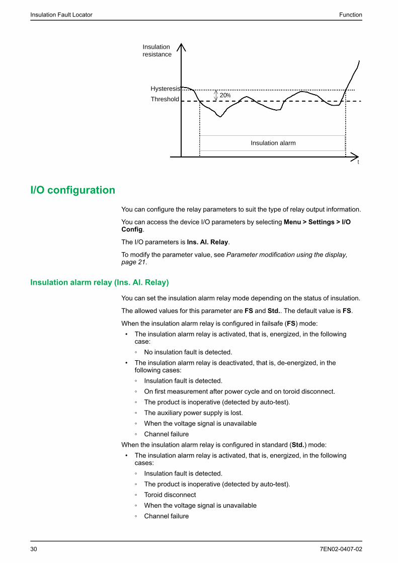
An insulation alarm is cleared when the insulation level reaches 20% above thethreshold.
Insulation alarm threshold hysteresis
A hysteresis is applied to limit the error in the insulation alarm due to fluctuationsin the measurement when approaching threshold value.
A hysteresis principle is applied:• When the insulation value measured decreases and falls below the setting
threshold, the insulation alarm is triggered or the countdown is started if aninsulation alarm time delay has been set.
• When the insulation value measured increases and exceeds 1.2 times the setthreshold (i.e. the setting threshold +20%), the insulation alarm isdeactivated.
The following diagrams show the behaviors:• Without hysteresis:
Threshold
Insulation alarm
Insulation alarm
Insulation alarm
t
Insulation resistance
• With hysteresis:
7EN02-0407-02 29
Insulation Fault Locator Function
20%Threshold
Insulation alarm
Hysteresis
t
Insulation resistance
I/O configurationYou can configure the relay parameters to suit the type of relay output information.
You can access the device I/O parameters by selectingMenu > Settings > I/OConfig.
The I/O parameters is Ins. Al. Relay.
To modify the parameter value, see Parameter modification using the display,page 21.
Insulation alarm relay (Ins. Al. Relay)
You can set the insulation alarm relay mode depending on the status of insulation.
The allowed values for this parameter are FS and Std.. The default value is FS.
When the insulation alarm relay is configured in failsafe (FS) mode:• The insulation alarm relay is activated, that is, energized, in the following
case:◦ No insulation fault is detected.
• The insulation alarm relay is deactivated, that is, de-energized, in thefollowing cases:◦ Insulation fault is detected.◦ On first measurement after power cycle and on toroid disconnect.◦ The product is inoperative (detected by auto-test).◦ The auxiliary power supply is lost.◦ When the voltage signal is unavailable◦ Channel failure
When the insulation alarm relay is configured in standard (Std.) mode:• The insulation alarm relay is activated, that is, energized, in the following
cases:◦ Insulation fault is detected.◦ The product is inoperative (detected by auto-test).◦ Toroid disconnect◦ When the voltage signal is unavailable◦ Channel failure
30 7EN02-0407-02

Function Insulation Fault Locator
• The insulation alarm relay is deactivated, that is, de-energized, in thefollowing cases:◦ No insulation fault is detected.◦ On first measurement after power cycle◦ The auxiliary power supply is lost.
R measurement
Insulation measurements
The device monitors the insulation per connected channel of ungrounded powersystem.
The device measures and displays the insulation resistance R (Ω) continuously for12 channels.
To view these values, navigate to Menu > Monitoring. To view each channelmeasurements, use the contextual menu buttons.
Monitoring power system insulationThe device monitors the ungrounded power system insulation in resistance inaccordance with the following timing diagram which represents the defaultsettings:
10 2 3 40 2 4
Display
Threshold
Hysteresis
1 42 3
Insulation
Standard
FailsafeRelay
NC C NO8 7 6
NC C NO8 7 6
NC C NO8 7 6
NC C NO8 7 6
NC C NO8 7 6
NC C NO8 7 6
NC C NO8 7 6
NC C NO8 7 6
INSULATION
200R = k
1k 10k 100k 1M 10M100
=
CHANNEL - 4
4
50 k
10
INS.ALARM
R =
1k 10k 100k 1M 10M100
=
5004
CHANNEL - 4
50 k
10
INS.ALARM
1k 10k 100k 1M 10M10010
4
CHANNEL - 4
500R =
= 50 k
INSULATION
200R = k
1k 10k 100k 1M 10M100
=
CHANNEL - 4
4
50 k
10
1 Network insulation is normal and no alarm on any channel.
2 An insulation fault occurred on channel 4. Active alarm is displayed on channel 4. Pressbutton to acknowledge the alarm. See Relay Mode, page 30 for more information on relaymodes.
3 An insulation fault occurred on channel 4. Active alarm acknowledged.
4 The insulation fault is corrected. The alarm LED turns off. The device reverts to normal status.
Insulation fault logThe device records the details of the 240 most recent fault events. You can accessall the 240 logs through HMI and communication. The fault events are triggered byinsulation fault status.
Event 1 is the event that was recorded most recently and event 240 is the oldestrecorded event.
The oldest event is deleted when a new event occurs (the table is not reset).
7EN02-0407-02 31

Insulation Fault Locator Function
By referring to this information, the performance of the distribution system can beimproved and maintenance work is facilitated.
Insulation fault log display screen
You can the view the details of an insulation fault event by navigating toMenu >Logging.
LOGGING
100
CHANNEL - 4
4
01
07
INS.ALARM
01.09.2018 - 09:49
01.09.2018 - 09:52
R =
1
2
3
4
7
9
5
6
8
1 Insulation fault value recorded
2 Type of fault recorded:Insulation fault
NOTE: Only insulation fault is recorded as primary record.
3 Date and time when the fault appearedNOTE: This information is stored as primary record.
4 Date and time when the fault disappeared due to any one of the following event:
• Insulation fault acknowledgement
• Power failure while on active alarm.
• Toroid disconnect while on active alarm.
• Voltage signal unavailable while on active alarm.
• Product or channel error while on active alarm.
• Automatic commissioning initiated while on active alarm.NOTE: This information is stored as secondary record.
5 Number of the event displayed
6 Total number of events recorded
7 Name of the channel, where the log is recorded
8 Number of the channel, where the log is recorded
9 Up and down arrows: Use to view recorded events
ResetYou can reset logs. Further, you can perform factory reset.
You can access the device reset parameters by selecting Menu > Settings >Reset.
The reset parameters are Reset Logs and Factory Reset.
On performing reset of logs, the existing logs information is erased but the settingsparameter value remains unchanged. On performing factory reset, the devicerestarts and automatic commissioning is initiated. Also, settings parameter valuesare reset to default.
The complete list of settings parameters, its default value, and allowed values are:
32 7EN02-0407-02

Function Insulation Fault Locator
Parameter Default Value Allowed Values
Ins. Alarm 50 kΩ 50...200 kΩ
Channel Name CHANNEL – 1 toCHANNEL – 12 for 12channels
• A to Z• a to z• 0 to 9• Special characters (Hyphen-minus (-), Slash
(/), Percent(%), Full stop (.), (blank))The length of the channel name is automaticallyadjusted depending on the character selection. Forexample, if the channel name contains only thecharacter “W”, then the maximum length is 8characters and if the channel name contains only thecharacter “I”, then the maximum length is 18characters.
Ins. Al. Relay FS • FS• Std.
Address 1 1...247
Baudrate 19200 • 4800• 9600• 19200• 38400
Parity Even • None• Even• Odd
ModifyPassword
0000 0000...9999
Activation(Password)
OFF • ON• OFF
Contrast 50% 10...100%
Backlight 100% 10...100%
Auto-test
Auto test overview
The device performs auto-test in background to detect any potential faults in itsinternal and external circuits.
The device’s auto test function tests:• The product: indicator lights, internal electronics.• The measuring chain and the insulation alarm relay.You can initiate auto test by pressing the T contextual menu button on theSummary screen. Auto test is disabled during insulation fault, product error, orsystem error.
Auto test sequence
During auto test, the device’s indicator lights illuminate and information is shownon the display.
The following LEDs turn ON in sequence and turn OFF after the predefined time:1. Alarm Orange2. No Alarm Green3. Product Status Red4. Product Status Green5. Communication Orange
7EN02-0407-02 33

Insulation Fault Locator Function
The relay toggles.• If the auto test is successful, the following screen appears for 3 seconds and
a status screen is displayed:
• If the auto test fails, the Product Status LED turns ON and a message isdisplayed to indicate that the product is malfunctioning. Disconnect theauxiliary power supply of device and reconnect. If the fault persists, contacttechnical support.
34 7EN02-0407-02

Communication Insulation Fault Locator
Communication
Communication parametersBefore initiating any communication with the device, you must configure theModbus communication port. You can configure communication parameters byselecting (Menu > Settings > Modbus).
The communication parameters and its allowed and default values are as follows:
Parameter Default value Allowed values
Address 1 1...247
Baud rate 19200 • 4800• 9600• 19200• 38400
Parity Even • None• Even• Odd
To modify the parameter value, see Parameter modification using the display,page 21.
In point-to-point mode, when the device is directly connected to a computer, thereserved address 248 can be used to communicate with the device irrespective ofthe device internal address.
Modbus functionsThe device supports Modbus function codes.
Function Code Function Name
Decimal Hexadecimal
3 0x03 Read Holding Registers 1
4 0x04 Read Input Registers 1
6 0x06 Write Single Register
8 0x08 Diagnostic Modbus
16 0x10 Write Multiple Registers
43 / 14 0x2B / 0E Read Device Identification
43 / 15 0x2B / 0F Get Date/Time
43 / 16 0x2B / 10 Set Date/Time
Read Device Identification request
Number Type Value
0 VendorName Schneider Electric
1 ProductCode IMDIFL12H
2 MajorMinorRevision XXX.YYY.ZZZ
3 VendorURL www.schneider-electric.com
4 ProductName Insulation Fault Locator
5 ModelName IFL12H
7EN02-0407-02 35
1. The Read Holding and Read Input registers are identical.

Insulation Fault Locator Communication
The device answers any type of requests (basic, regular, extended).
Modbus register table formatRegister tables have the following columns.
Column heading Description
Address The address of the Modbus, in decimal (dec) and hexadecimal (hex)formats.
Register The register of the Modbus, in decimal (dec) and hexadecimal (hex)formats.
R/W Read only (R) or read/write (R/W) register.
Unit The unit in which the information is expressed.
Type The coding data type.
Range Permitted values for this variable, usually a subset of what the formatallows.
Description Provides information about the register and the values applied.
Modbus registers tableThe following table lists the Modbus registers that apply to your device.
System status registers
Address Register R/W
Unit Type Range Description
dec hex dec hex
100 64 101 65 R – Uint16 – Product identifier
17032 - IFL12H
114..115 72...73 115...116 73...74 R – Uint32 – Product state• Bit1 - Reserved• Bit2 - Auto test• Bit3 - Commissioning• Bit4 - Safe state• Bit5 - Monitoring• Bit6 - Channel error• Bit7 - Product error• Bit8 - System error• Bit9 - Reserved• Bit10 - Reserved
116 74 11722 75 R – Uint16 – Product error codes• 0XFFFF - No error• 0x0000 - Unknown error• 0x0DEF - Undefined model• 0xAF00 - Auto-test failure• 0xBE00 - Metering• 0xC0F1 - Configuration error• 0x5EFA - Sensor call
problem• 0xD1A1 - Glued IO• 0xD1A2 - RAM• 0xD1A3 - EEPROM• 0xD1A4 - Relay• 0xD1A5 - Status input• 0xD1A6 - Flash
36 7EN02-0407-02

Communication Insulation Fault Locator
System status registers (Continued)
Address Register R/W
Unit Type Range Description
dec hex dec hex
• 0xD1A7 - SIL• 0xE000 - NMI interrupt• 0xE001 - Hard fault
exception• 0xE002 - Memory fault
exception• 0xE003 - Bus fault exception• 0xE004 - Usage fault
exception• 0xE005 - Unexpected
interrupt• 0xFAF5 - Unexpected
interrupt
120...1-39
78...8B 121...140 79...8C R – UTF8 – Product family
140...1-59
8C...9F 141...160 8D...A0 R/W
– UTF8 – Product name (User applicationname)
160...1-79
A0...B3 161...180 A1...B4 R – UTF8 – Product codeIMDIFL12H
180...1-99
B4...C7 181...200 B5...C8 R – UF8 – Manufacturer: Schneider Electric
208...2-19
D0...DB
209...220 D1...DC R – UF8 – ASCII serial number
220 DC 221 DD R – Uint16 – Manufacturing unit identifier
227...2-46
E3...F6 228...247 E4...F7 R – UTF8 – Product capability
247...2-66
F7...10-A
248...267 F8...10B R – UTF8 – Product modelIFL12H
300...3-06
12C...-132
301...307 12D...133 R – Uint16 – Date and time in 7 register formatThe following parameterscorrespond to each register:• 300 - Year• 301 - Month• 302 - Day• 303 - Hour• 304 - Minute• 305 - Second• 306 - Millisecond
307...3-10
133...1-36
308...311 134...137 R/W
– Uint16 – Date and time in TI081 format.See Date and time (TI081 format),page 45.
320...3-24
140...1-49
321...325 141...145 R – Uint16 – Present firmware version• X represents the primary
revision number, which isencoded in register 321
• Y represents the secondaryrevision number, which isencoded in register 322
• Z represents the qualityrevision number, which isencoded in register 323
325...3-29
145...1-49
326...330 146...14A R – Uint16 – Previous firmware version• X represents the primary
revision number, which isencoded in register 326
• Y represents the secondaryrevision number, which isencoded in register 327
7EN02-0407-02 37

Insulation Fault Locator Communication
System status registers (Continued)
Address Register R/W
Unit Type Range Description
dec hex dec hex
• Z represents the qualityrevision number, which isencoded in register 328
340...3-44
154...1-58
341...345 155...159 R – Uint16 – Boot firmware version• X represents the primary
revision number, which isencoded in register 341
• Y represents the secondaryrevision number, which isencoded in register 342
• Z represents the qualityrevision number, which isencoded in register 343
500...5-05
1F4...1-F9
501...506 1F5...1FA R – UTF8 – Hardware revision
550...5-55
226...2-2B
551...556 227...22C R – UTF8 – Existing OS version
556...5-61
22C...-231
557...562 22D...232 R – UTF8 – Previous OS version
562...5-67
232...2-37
563...572 233...23C R – UTF8 – Existing RS/Boot version
586...5-91
24A...-24F
587...592 24B...250 R – UTF8 – Existing SIL OS version
Modbus
Address Register R/W
Unit Type Range Description
dec hex dec hex
750 2EE 751 2EF R/W
– Uint16 1...247 Device address
Default value: 1
751 2EF 752 2F0 R/W
– Uint16 • 0 = 4800• 1 = 9600• 2 = 19200• 3 = 38400
Baud rate
Default value: 2 (19200)
752 2F0 753 2F1 R/W
– Uint16 • 0 = Even• 1 = Odd• 2 = None
Parity
Default value: 0 (Even)
38 7EN02-0407-02

Communication Insulation Fault Locator
Insulation alarm
Address Register R/W Unit Type Range Description
dec hex dec hex
1102 44E 1103 44F R – Uint16 – Product alarm status• Bit 1...12 - Channel status
for channel 1 to 12respectivelyThis bit is set for thecorresponding channel forany of the following states:◦ Active alarm◦ Alarm acknowledged◦ Toroid disconnect◦ First measurement◦ Channel error
• Bit 13 - System errorThis bit is set for thefollowing states:◦ Voltage signal
unavailable◦ Toroid disconnect◦ No toroid
• Bit 14 - Product errorThis bit is set for Productfailure state.
1103 44F 1104 450 R – Uint16 – Compliment for product alarmstatus
1104...-1105
450...45-1
1105...1-106
451...452 R – Uint32 0...0XFFFFFFFF Status counter
7EN02-0407-02 39

Insulation Fault Locator Communication
Insulation alarm (Continued)
Address Register R/W Unit Type Range Description
dec hex dec hex
1110...1-111
456...45-7
1111...1-112
457...458 R – Uint32 – Product status• 0 - No alarm• Bit 1 - Active alarm• Bit 2 - Reserved• Bit 3 - Reserved• Bit 4 - Alarm acknowledged• Bit 5 - Reserved• Bit 6 - Reserved• Bit 7 - Reserved• Bit 8 - Reserved• Bit 9 - First measurement• Bit 10 - Reserved• Bit 11 - Reserved• Bit 12 - Reserved• Bit 13 - Auto test• Bit 14 - Commissioning• Bit 15 - Reserved• Bit 16 - Uncommissioned• Bit 17 - Locating signal
unavailable• Bit 18 - Reserved• Bit 19 - Reserved• Bit 20 - Reserved• Bit 21 - Reserved• Bit 22 - Toroid disconnect• Bit 23 - Reserved• Bit 24 - Reserved• Bit 25 - Product error• Bit 26 - Channel error• Bit 27 - Reserved• Bit 28 - Reserved• Bit 29 - Reserved• Bit 30 - Reserved• Bit 31 - Reserved• Bit 32 - Power Down
1112...1-134
458...46-E
1113...1-135
459...46F R – Uint32 – Channel (1 to 12) status. Eachchannel represents 2 registers.• 0 - No alarm• Bit 1 - Active alarm• Bit 2 - Reserved• Bit 3 - Reserved• Bit 4 - Alarm acknowledged• Bit 5 - Reserved• Bit 6 - Reserved• Bit 7 - Reserved• Bit 8 - Reserved• Bit 9 - First measurement• Bit 10 - Reserved• Bit 11 - Reserved• Bit 12 - Reserved• Bit 13 - Auto test• Bit 14 - Commissioning• Bit 15 - Reserved• Bit 16 - Uncommissioned• Bit 17 - Locating signal
unavailable
40 7EN02-0407-02

Communication Insulation Fault Locator
Insulation alarm (Continued)
Address Register R/W Unit Type Range Description
dec hex dec hex
• Bit 18 - Reserved• Bit 19 - Reserved• Bit 20 - Reserved• Bit 21 - Reserved• Bit 22 - Toroid disconnect• Bit 23 - Reserved• Bit 24 - Reserved• Bit 25 - Product error• Bit 26 - Channel error• Bit 27 - Reserved• Bit 28 - Reserved• Bit 29 - Reserved• Bit 30 - Reserved• Bit 31 - Reserved• Bit 32 - Power Down
Diagnostics
Address Register R/W Unit Type Range Description
dec hex dec hex
2001...-2004
7D1...7-D4
2002...2-005
7D2...7D5 R – Date/Time
– Total uptime since first power upof product.
Registers correspond to (result -01/01/2000) = total uptime.
TI081 date format (See Date andtime (TI081 format), page 45)
2005...-2006
7D5...7-D6
2006...2-007
7D6...7D7 R – Uint32 – Total number of power cyclessince first power-up of the product
2050 802 2051 803 W – Uint16 – Write 0x1919 to reset factorysettings (default factory settings)
2051 803 2052 804 W – Uint16 – Write 0xF0A1 to reset all logs
CRC
Address Register R/W Unit Type Range Description
dec hex dec hex
2500...-2501
9C4...9-C5
2501...2-502
9C5...9C6 R – Uint32 – Application CRC value.
2502...-2503
9C6...9-C7
2503...2-504
9C7...9C8 R – Uint32 – Boot CRC value
Settings
Address Register R/W Unit Type Range Description
dec hex dec hex
2997...-2998
BB5...BB6
2998...2-999
BB6...BB7 R – Uint16 – Total number of settings changedsince first power-up. Incrementedby 1 for each change of one orseveral parameters.
3001 BB9 3002 BBA R/W – Uint16 • 1= Standard• 2 = Failsafe
Insulation alarm relay logiccommand
Default value: 2 (Failsafe)
3014 BC6 3015 BC7 R/W – Uint16 0000...9999 Password
Default value: 0000
7EN02-0407-02 41

Insulation Fault Locator Communication
Settings (Continued)
Address Register R/W Unit Type Range Description
dec hex dec hex
3015 BC7 3016 BC8 R/W – Uint16 • 0 = OFF• 1 = ON
Password protection
Default value: 0 (passwordprotection deactivated)
3016 BC8 3017 BC9 R/W – Uint16 • 0 = English• 1 = French• 2 = Spanish• 3 = Russian• 4 = Chinese• 5 = Italian• 6 = German• 7 = Portuguese
Interface language
Default value: 0 (English)
3017 BC9 3018 BCA R/W % Uint16 10...100% Screen contrast
Default value: 50%
3018 BCA 3019 BCB R/W % Uint16 10...100% Screen brightness.
Default value: 100%
3042 BE2 3043 BE3 W – Uint16 – Commissioning mode
Write 0xAABB to entercommisioning
Write 0xBBAA to exitcommisioning
Monitoring
Address Register R/W Unit Type Range Description
dec hex dec hex
10000..-.10023
2710...-2727
10001...-10024
2711...27-28
R Ohm Float32 – Resistance for 12 channels. Eachchannel represents 2 registers.
10072..-.10083
2758...-2763
10073...-10084
2759...27-64
R – Unit16 • 0 = Equal• 1 = Under• 2 = Over• 3 = UnderStrict• 4 = OverStrict
R equality for 12 channels. Eachchannel represents 1 register.
NOTE: The following registers is applicable for channel 1. For channel 2register, add “30” value to channel 1 register. For channel 3 register, add “30”value to channel 2 register and so on.
Settings – For individual channels
Address Register R/W Unit Type Range Description
dec hex dec hex
11000..-.11008
2A-F8...2-B00
11001...-11009
2AF9...2-B01
R/W – UTF8 Allowed length : 18characters
Name of the channel. The mostsignificant byte of the fist registercontains first character. The lastsignificant byte of last registercontains last character.Default value: CHANNEL - 1
11009..-.11010
2B01...-2B02
11010...-11011
2B02...2-B03
R/W Ohm Uint32 50...200 kΩ Insulation alarm threshold
Default value: 50 kΩ
11016 2B08 11017 2B09 R/W turns Uint16 • 0 =Uncommissioned
• 470, 1000 = Auto• 300...3000 =
Manual
Number of toroid turns
Default value: 0
42 7EN02-0407-02
Communication Insulation Fault Locator
Logging
Address Register R/W Unit Type Range Description
dec hex dec hex
19996..-.19997
4E1-C...4E1-D
19997...-19998
4E1D...4-E1E
R – Unit32 – Roll over counter
19998..-.19999
4E1-E...4E1F
19999...-20000
4E1F...4-E20
R – Uint16 1...240 Number of event records
20001 4E21 20002 4E22 R – Uint16 – Most recent record number
20002..-.20013
4E22...-4E2D
20003...-20014
4E23...4-E2E
R – Record – Record 1
20014..-.20025
4E2-E...4E39
20015...-20026
4E2F...4-E3A
R – Record – Record 2
...
20710..-.20721
50E6...-50F1
20711...-20722
50E7...50-F2
R – Record – Record 60
22870..-.22881
5956...-5961
22871...-22882
5957...59-62
R – Record – Record 240
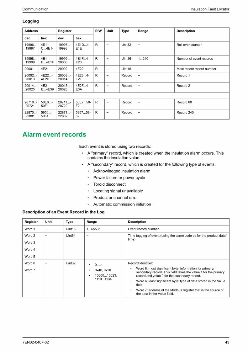
Alarm event recordsEach event is stored using two records:• A "primary" record, which is created when the insulation alarm occurs. This
contains the insulation value.• A "secondary" record, which is created for the following type of events:◦ Acknowledged insulation alarm◦ Power failure or power cycle◦ Toroid disconnect◦ Locating signal unavailable◦ Product or channel error◦ Automatic commission initiation
Description of an Event Record in the Log
Register Unit Type Range Description
Word 1 – Uint16 1...65535 Event record number
Word 2
Word 3
Word 4
Word 5
– Uint64 – Time tagging of event (using the same code as for the product date/time)
Word 6
Word 7
– Uint32 • 0….1• 0x40, 0x20• 10000...10023,
1110...1134
Record identifier:• Word 6, most significant byte: information for primary/
secondary record. This field takes the value 1 for the primaryrecord and value 0 for the secondary record.
• Word 6, least significant byte: type of data stored in the Valuefield.
• Word 7: address of the Modbus register that is the source ofthe data in the Value field.
7EN02-0407-02 43

Insulation Fault Locator Communication
Description of an Event Record in the Log (Continued)
Register Unit Type Range Description
Word 8
Word 9
Word 10
Word 11
– Uint64 – Depending on the type of record (primary or secondary):• Primary record (when the event occurs): Insulation resistance
value (in Ohm) when the event occurred (encoded in Float32in the last 2 registers).
• Secondary record (for the earlier list of events) (encoded inUint32 in the last 2 registers)
Word 12 – Uint16 1...65534 Primary/secondary record identifier for the event:• In the case of a primary record for an event, this identifier is an
odd integer; numbering starts at 1 and the number isincremented by 2 for each new event.
• In the case of a secondary record for an event, this identifier isequal to the primary record identifier plus 1.
Example of an event
The next 2 records relate to an example insulation alarm that occurred on October1, 2010 at 12:00 pm and was acknowledged at 12:29 pm.
Record number: 1
Address Register Unit Type Value Description
dec hex dec hex
20002 4E22 20003 4E23 – Uint16 1 Record number
20003 4E23 20004 4E24 – Uint64 • 10• 0• 10• 1• 12• 0• 0
Date when insulation alarm occurred(October 1, 2010, 12:00 pm)
20007 4E27 20008 4E28 – Uint32 • 1• 0x40• 100-
00
Record identifier:• Primary record plus secondary
record• Float32 value (insulation
resistance)• Value of register 10000 (register
for insulation resistancemonitoring)
20009 4E29 20010 4E2A Ohm Uint64 10000 Insulation resistance value at the timeof the insulation alarm
20013 4E2D 20014 4E2E – Uint16 1 Secondary record identifier for theevent
Record number: 2
Address Register Unit Type Value Description
dec hex dec hex
20014 4E2E 20015 4E2F – Uint16 2 Record number
20015 4E2F 20016 4E30 – Uint64 • 10• 0• 10• 1• 12• 29• 0
Date when insulation alarmacknowledged (October 1, 2010, 12:29pm)
44 7EN02-0407-02

Communication Insulation Fault Locator
Record number: 2 (Continued)
Address Register Unit Type Value Description
dec hex dec hex
20019 4E33 20020 4E34 – Uint32 • 1• 0x20• 1112
Record identifier:• Secondary record• Uint32 value (alarm
acknowledged)• 1112 register value (channel
status).
20021 4E35 20022 4E36 – Uint64 8 Value of insulation alarm register at thetime of insulation alarmacknowledgement
20025 4E39 20026 4E3A – Uint16 2 Secondary record identifier for theevent
Date and time (TI081 format)The following structure is used for date-time information exchange using Modbusprotocol.
The date/time are encoded in 8 bytes as follows:
b15 b14 b13 b12 b11 b10 b09 b08 b07 b06 b05 b04 b03 b02 b01 b00 Word
0 0 0 0 0 0 0 0 R4 Y Y Y Y Y Y Y Word 1
0 0 0 0 M M M M WD WD WD D D D D D Word 2
SU 0 0 H H H H H iV 0 mn mn mn mn mn mn Word 3
ms ms ms ms ms ms ms ms ms ms ms ms ms ms ms ms Wrod 4
• R4: Reserved bit (reserved by IEC870-5-4), set to 0• Y - Years◦ 1 byte◦ Value from 0...127 (1/1/2000 to 31/12/2127)
• M - Months◦ 1 byte◦ Value from 1...12
• D - Days◦ 1 byte◦ Value from 1...31
• H - Hours◦ 1 byte◦ Value from 0...23
• mn - Minutes◦ 1 byte◦ Value from 0...59
• ms - Milliseconds◦ 2 byte◦ Value from 0...59999
The following fields are in CP56Time2a standard and are considered as optional:• WD - Week Day◦ If not used, set to 0 (1 = Sunday, 2 = Monday...)◦ Value from 1...7
7EN02-0407-02 45
Insulation Fault Locator Communication
• SU - Summertime◦ If not used, set to 0 (0 = standard time, 1 = summertime)◦ Value from 0...1
• iV - Validity of the information contained in the structure◦ If not used, set to 0 (0 = valid, 1 = not valid or not synchronized in system)◦ Value from 0...1
This information is encoded in binary form.
46 7EN02-0407-02

Maintenance Insulation Fault Locator
Maintenance
Safety precautionsThe following safety precautions must be thoroughly implemented beforeattempting to commission the system, repair electrical equipment or carry outmaintenance.
Carefully read and follow the safety precautions described below.
DANGERHAZARD OF ELECTRIC SHOCK, EXPLOSION, OR ARC FLASH• Apply appropriate personal protective equipment (PPE) and follow safe
electrical work practices. See NFPA 70E in the USA, CSA Z462 orapplicable local standards.
• Turn off all power supplying this device and the equipment in which it isinstalled before working on the device or equipment.
• Always use a properly rated voltage sensing device to confirm that all poweris off.
Failure to follow these instructions will result in death or serious injury.
NOTICEEQUIPMENT DAMAGE• Do not open this unit.• Do not attempt to repair any components of this product or any of its
accessory products.Failure to follow these instructions can result in equipment damage.
Product status light indicatorIf the Product status light indicator is red, there is an error in the power system oryour device.
The error is one of the following cases:• Auto test not OK• Product error• System error• No toroid• Toroid disconnect• Locating signal unavailable
TroubleshootingThere are some checks you can perform to try to identify potential issues with thedevice’s operation.
The following table describes potential problems, their possible causes, checksyou can perform and possible solutions for each. After referring to this table, if youcannot resolve the problem, contact your local Schneider Electric salesrepresentative for assistance.
7EN02-0407-02 47

Insulation Fault Locator Maintenance
Potential problem Possible cause Possible solution
The device displays nothing when switchedon.
No power supply to the device. Check that the auxiliary power supply ispresent.
The auxiliary power supply is not compliant. Check the auxiliary voltage.
The device notified an insulation fault, butyour system shows no signs of abnormalbehavior.
The insulation alarm threshold is notappropriate.
Check the value of the insulation alarmthreshold. Modify the insulation alarmthreshold as appropriate.
You deliberately created an insulation fault,but the device failed to detect it.
The resistance value used to simulate thefault is greater than the value of theinsulation alarm threshold.
Use a resistance value that is lower than theinsulation alarm threshold or modify theinsulation alarm threshold.
The fault is not detected between neutraland ground.
Start again ensuring you are betweenneutral and ground.
IMD detecting fault, the device is not The insulation alarm threshold is notappropriate.
Check the value of the insulation alarmthreshold. Modify the insulation alarmthreshold as appropriate.
There are faults on the same phase onseveral feeders and insufficient signal tolocate fault with the selected devicethreshold.
Fault is on an ungrounded system locationnot monitored by the device, such as thebus between the branches
Check for insulation fault upstream of thedevice with the mobile fault location kit.
Device alarming but IMD not detecting fault The insulation alarm threshold is notappropriate.
Check the value of the insulation alarmthreshold. Modify the insulation alarmthreshold as appropriate.
Ungrounded system insulation may havechanged over time or under differentconditions.
Review insulation resistance history on theIMD and identify if its threshold needschanges.
Alarm relay behaviour inverted (off whenshould be on, or vice versa)
Incorrect relay wiring Change relay wiring to provide the expectedrelay behaviour.
Alarm still on even after fault fixed Second fault exists on indicated branchcircuit (same live conductor, same feeder)
Check and correct the second fault.
The product status LED is red and thedisplay indicates that an error occurredduring the auto-test.
Internal error Briefly disconnect the auxiliary power supplyto the device.
Although the device is being supplied withpower, the product status LED does not lightup.
Faulty indicator light. Restart the auto-test and check that theproduct status LED lights up briefly.
The alarm LED does not light up in theevent of a fault.
Faulty indicator light. Restart the auto-test and check that thealarm LED lights up briefly.
48 7EN02-0407-02

Specifications Insulation Fault Locator
SpecificationsThis section provides specifications for the device.
Auxiliary power
AC 110...230 V LN / 400 V LL ± 15% 50/60 Hz• < 22 VA at 440 V• < 8 VA at 230 V
DC 125...250 V ± 15% < 10 W
Monitored network
AC / DC 230 V
Maximum leakage capacitance 5 µF
Electrical
Insulation resistance range 100 Ω...250 kΩ
Response time 5 s
Accuracy As per IEC61557–9
Threshold 50...200 kΩ
Hysteresis ± 20%
Relay configuration • Standard• Failsafe
Relay maximum AC voltage / current 250 V / 6 A
Relay maximum AC load 1500 VA
Relay maximum DC voltage / current 48 V / 1 A
Mechanical
Weight 0.55 kg (1.12 lb)
Mounting position Vertical orientation only
IP degree of protection • IP20 : Other sides• IP54 : Front
Installation category • 300 V, CAT III, Pollution degree 2• 600 V, CAT II, Pollution degree 2
Environment
Operating temperature -25...70 °C (-13...158 °F)
RH non-condensing 5...95%
Maximum dewpoint 37 °C (99 °F)
Storage temperature -40...85 °C (-40...185 °F)
Operating altitude ≤ 3000 m (9843 ft)
Usage • For indoor use only• Not suitable for wet locations
Standards
Product IEC 61557-9
Safety IEC/UL 61010-1
7EN02-0407-02 49

Insulation Fault Locator Specifications
Standards (Continued)
EMC • IEC 61326-2-4• IEC 61326-3-1• IEC 61000-6-2• IEC 61000-6-4
Installation IEC 60364-7-710
50 7EN02-0407-02


Schneider Electric35 rue Joseph Monier92500 Rueil MalmaisonFrance
+ 33 (0) 1 41 29 70 00
www.schneider-electric.com
As standards, specifications, and design change from time to time,please ask for confirmation of the information given in this publication.
© 2019 – Schneider Electric. All rights reserved.
7EN02-0407-02