viing 095c sris section 351 rvrsing mcnicl inrnl gr pumps page...
TRANSCRIPT
VIKING PUMP • A Unit of IDEX Corporation • Cedar Falls, IA ©2012
Section 351Page 351.1Issue ASERIES 095C
VIKING 095C SERIES REVERSING MECHANICAL INTERNAL GEAR PUMPS
Displacements No. 4
Flow RangeGPM 4 to 35
LPM 15 to 134
Pressure RangePSI 232
Bar 16
Temperature Range
°F -40° to 225°
°C -40° to 107°
Viscosity RangeSSU 150 to 70,000
cSt 33 to 140,000
Pump Size ml/rev GPM LPMHJ095C 45 14 54
HL095C 63 20 75
A095C 80 25 96
AS095C 112 35 134
Operating Range:
Theoretical Displacement, Nominal Flow Rates at 1750 GPM:
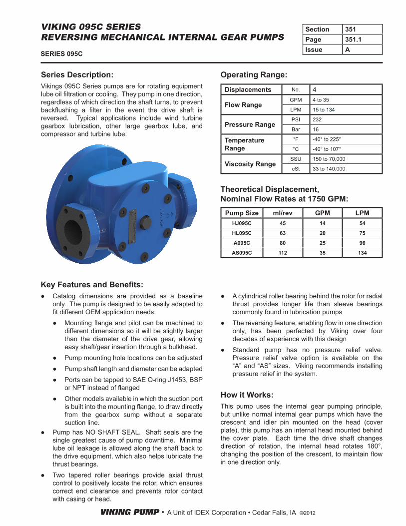
Series Description:Vikings 095C Series pumps are for rotating equipment lube oil filtration or cooling. They pump in one direction, regardless of which direction the shaft turns, to prevent backflushing a filter in the event the drive shaft is reversed. Typical applications include wind turbine gearbox lubrication, other large gearbox lube, and compressor and turbine lube.
Key Features and Benefits:● Catalog dimensions are provided as a baseline
only. The pump is designed to be easily adapted to fit different OEM application needs:
● Mounting flange and pilot can be machined to different dimensions so it will be slightly larger than the diameter of the drive gear, allowing easy shaft/gear insertion through a bulkhead.
● Pump mounting hole locations can be adjusted ● Pump shaft length and diameter can be adapted ● Ports can be tapped to SAE O-ring J1453, BSP
or NPT instead of flanged ● Other models available in which the suction port
is built into the mounting flange, to draw directly from the gearbox sump without a separate suction line.
● Pump has NO SHAFT SEAL. Shaft seals are the single greatest cause of pump downtime. Minimal lube oil leakage is allowed along the shaft back to the drive equipment, which also helps lubricate the thrust bearings.
● Two tapered roller bearings provide axial thrust control to positively locate the rotor, which ensures correct end clearance and prevents rotor contact with casing or head.
● A cylindrical roller bearing behind the rotor for radial thrust provides longer life than sleeve bearings commonly found in lubrication pumps
● The reversing feature, enabling flow in one direction only, has been perfected by Viking over four decades of experience with this design
● Standard pump has no pressure relief valve. Pressure relief valve option is available on the “A” and “AS” sizes. Viking recommends installing pressure relief in the system.
How it Works:This pump uses the internal gear pumping principle, but unlike normal internal gear pumps which have the crescent and idler pin mounted on the head (cover plate), this pump has an internal head mounted behind the cover plate. Each time the drive shaft changes direction of rotation, the internal head rotates 180°, changing the position of the crescent, to maintain flow in one direction only.

VIKING PUMP • A Unit of IDEX Corporation • Cedar Falls, IA ©2012
Section 351Page 351.2Issue A SERIES 095C
VIKING 095C SERIES REVERSING MECHANICAL INTERNAL GEAR PUMPS
Materials of Construction
Component HJ095C, HL095C A095C, AS095C
Casing Cast Iron Cast Iron
Head Cast Iron Ductile Iron
Rotor Ductile Iron Ductile Iron
Idler Cast Iron Ductile Iron
Rotor Shaft and Idler Pin Steel Steel
Idler Bushing Carbon Graphite Carbon Graphite
O-Ring * Buna-N Buna-N
* Optional O-ring materials available
Specifications
② Model
Number
Port Size(SAE J518 Code 61)
①Nominal
Displacement
Maximum Developed Pressure
Maximum Speed
①Nominal
Capacity at Max. Speed
Maximum Hydrostatic
Pressure
②Minimum
Recommended Temperature
②Maximum
Recommended Temperature
Approximate Shipping Weight
(Pump Only)
Lip Seal Inches Gal/rev ml/rev PSI BAR RPM GPM LPM PSI BAR °F °C °F °C .Lb. Kg
HJ095C 1.5 0.012 45
232 161800
107 225 400 28 -40 -40 225 107
32 14
HL095C 1.5 0.017 63 32 14
A095C 2 0.021 801200
67 30
AS095C 2.5 0.030 112 68 31
① Nominal displacement and capacity based on 1500 SSU (330 cSt) liquid at 100 PSI (7 Bar).
Keyed, metric-dimensioned shaft for mounting drive gear
Idler
Rotor
Cover plate
Bracket pilot for mounting to drive equipment (machined
to fit OEM needs)
Spring tensioner to ensure smooth transition during
shaft rotation change
SAE J518 Code 61 flange ports, using metric fasteners
180° rotatable internal head with idler pin and crescent
Dual tapered roller bearings for axial thrust control
Cylindrical roller bearings behind rotor for radial thrust control
② Temperature limits shown for standard Buna-N O-rings. Optional elastomers offer lower or higher temperature capabilities.
VIKING PUMP • A Unit of IDEX Corporation • Cedar Falls, IA ©2012
Section 351Page 351.3Issue ASERIES 095C
VIKING 095C SERIES REVERSING MECHANICAL INTERNAL GEAR PUMPS
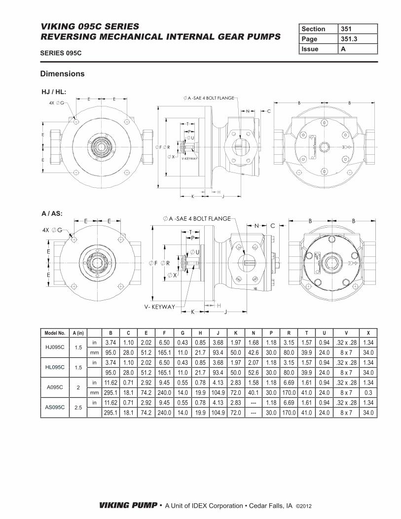
Model No. A (in) B C E F G H J K N P R T U V X
HJ095C 1.5in 3.74 1.10 2.02 6.50 0.43 0.85 3.68 1.97 1.68 1.18 3.15 1.57 0.94 .32 x .28 1.34
mm 95.0 28.0 51.2 165.1 11.0 21.7 93.4 50.0 42.6 30.0 80.0 39.9 24.0 8 x 7 34.0
HL095C 1.5in 3.74 1.10 2.02 6.50 0.43 0.85 3.68 1.97 2.07 1.18 3.15 1.57 0.94 .32 x .28 1.34
95.0 28.0 51.2 165.1 11.0 21.7 93.4 50.0 52.6 30.0 80.0 39.9 24.0 8 x 7 34.0
A095C 2in 11.62 0.71 2.92 9.45 0.55 0.78 4.13 2.83 1.58 1.18 6.69 1.61 0.94 .32 x .28 1.34
mm 295.1 18.1 74.2 240.0 14.0 19.9 104.9 72.0 40.1 30.0 170.0 41.0 24.0 8 x 7 0.3
AS095C 2.5in 11.62 0.71 2.92 9.45 0.55 0.78 4.13 2.83 --- 1.18 6.69 1.61 0.94 .32 x .28 1.34
295.1 18.1 74.2 240.0 14.0 19.9 104.9 72.0 --- 30.0 170.0 41.0 24.0 8 x 7 34.0
Dimensions
HJ / HL:
A / AS:
T
RF
K J
A -SAE 4 BOLT FLANGE
N C
UP
X
H
V-KEYWAY
B BE E
E
E
4X G
T
R
K J
A -SAE 4 BOLT FLANGEN C
F
U
P
X
HV- KEYWAY
B BEE
E
E
4X G

VIKING PUMP • A Unit of IDEX Corporation • Cedar Falls, IA ©2012
Section 351Page 351.4Issue A SERIES 095C
VIKING 095C SERIES REVERSING MECHANICAL INTERNAL GEAR PUMPS
Pump SizePump Speed (RPM)
520 640 780 950 1150 1450 1750
HJ095CHL095C 2.4 2.8 3.4 4.5 6.2 9.5 13.5
A095CAS095C 3.2 3.9 5.5 7.7 11.2 --- ---
1 m = 3.28 feet1 foot = 0.305 m① - At pump suction portN/A - Not Applicable - pump not rated for speeds listed.
PERFORMANCE CURVE NOTESPrinted performance curves are not available.
Performance curves can be electronically generated with the Viking Pump Selector Program. This program can be located on www.vikingpump.com/pumpselector for the general public.
For authorized distributors, this program can be found listed under the “Products” tab at www.idexconnect.com. Security passwords are required to access IDEXconnect.
Vacuum Pressure
(Inches-Mercury) In.-Hg.
(Kilopascal) kPa*
(lbf/in.2) PSI
(Kilopascal) kPa*
1 3.4 1 6.9
5 17 25 172
10 34 50 345
15 51 100 690
20 68 150 1034
25 85 200 1379
250 1724
*1 kPa = 1 bar
INLET CONDITIONS: The performance curves show “Based on 10 (or 15) In.-Hg.” which is Viking’s standard test condition. This is not the maximum vacuum capability of the pump.
NPSH (Net Positive Suction Head): The NPSHR (Net Positive Suction Head Required by the pump) is given in the table below and applies for viscosities through 750 SSU. NPSHA (Net Positive Suction Head Available in the system) must be greater than NPSHR.
For a complete explanation of NPSH, see Viking Application Data Sheet, AD-19.
Mechanical Efficiency =(Differential Pressure, PSI) (Capacity, GPM) (100)
(Horsepower, BHP) (1715)
095C SERIES NET POSITIVE SUCTION HEAD REQUIRED (NPSHR) ①
FEET OF LIQUID (SP. GR. 1.0), VISCOSITIES - 38 SSU TO 750 SSU
FOR VISCOSITIES ABOVE 750 SSU (NPSHR data not available): The performance curves are based on 15 In.-Hg. While vacuums up to 20 In.-Hg. will not generally result in any loss of capacity, it is recommended that the suction line size and possibly the pump port size be increased to hold the expected vacuum to 15 In.-Hg. or less, when measured at the pump suction port. Vacuum above 20 In.-Hg. should be avoided. (Refer to “Engineering Data” Catalog Section 510 for information helpful in determining suction line size.)
MECHANICAL EFFICIENCY: The Mechanical Efficiency (expressed in percent) can be calculated by using the following formula:
METRIC CONVERSION: The following table has been compiled for conversion to metric values.