vip x1600 module - bosch...
TRANSCRIPT
VIP X1600 Module
EN | 2 Quick Installation Guide | VIP X1600 Module
Bosch Security Systems | 2006-08 | V2.0
These instructions "Quick Installation Guide" show the mounting of a VIP X1600 module into a VIP X1600 base and its wiring. In the drawings the VIP X1600 module displayed in audio version stands for all versions.
Warning
You should always make yourself familiar with the required safety measures in the cor-responding chapter of the user's manual. You will find important details on the installa-tion and on the operation of the unit in the user's manual. These instructions "Quick Installation Guide" only show the basic installation of a VIP X1600 module; they are no substitute for the complete user's manual.
VIP X1600 Module | Quick Installation Guide EN | 3
Bosch Security Systems | 2006-08 | V2.0
Contents of Delivery
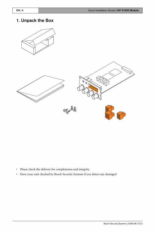
• VIP X1600 module Network Video Server, basic version or audio version
• Plug-in connectors
• Mounting kit for installation in VIP X1600 base
• Quick Installation Guide
EN | 4 Quick Installation Guide | VIP X1600 Module
Bosch Security Systems | 2006-08 | V2.0
1. Unpack the Box
• Please check the delivery for completeness and integrity.
• Have your unit checked by Bosch Security Systems if you detect any damages!
VIP X1600 Module | Quick Installation Guide EN | 5
Bosch Security Systems | 2006-08 | V2.0
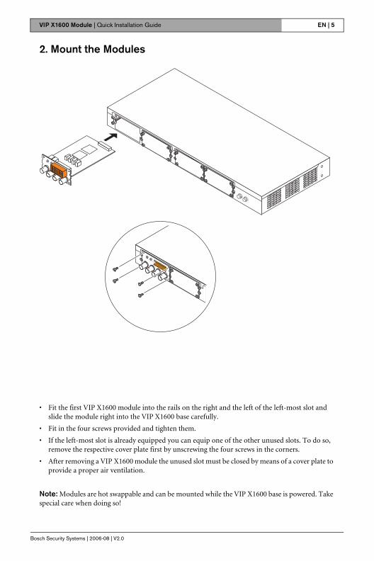
2. Mount the Modules
• Fit the first VIP X1600 module into the rails on the right and the left of the left-most slot and slide the module right into the VIP X1600 base carefully.
• Fit in the four screws provided and tighten them.
• If the left-most slot is already equipped you can equip one of the other unused slots. To do so, remove the respective cover plate first by unscrewing the four screws in the corners.
• After removing a VIP X1600 module the unused slot must be closed by means of a cover plate to provide a proper air ventilation.
Note: Modules are hot swappable and can be mounted while the VIP X1600 base is powered. Take special care when doing so!
EN | 6 Quick Installation Guide | VIP X1600 Module
Bosch Security Systems | 2006-08 | V2.0
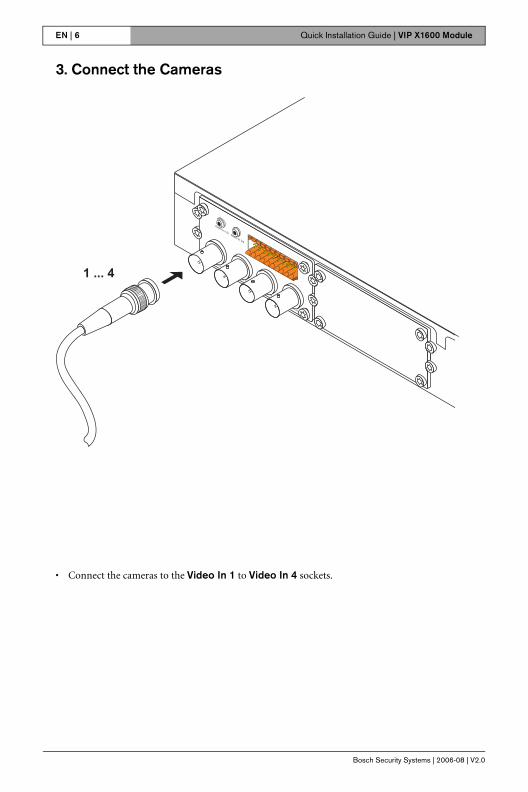
3. Connect the Cameras
• Connect the cameras to the Video In 1 to Video In 4 sockets.
VIP X1600 Module | Quick Installation Guide EN | 7
Bosch Security Systems | 2006-08 | V2.0
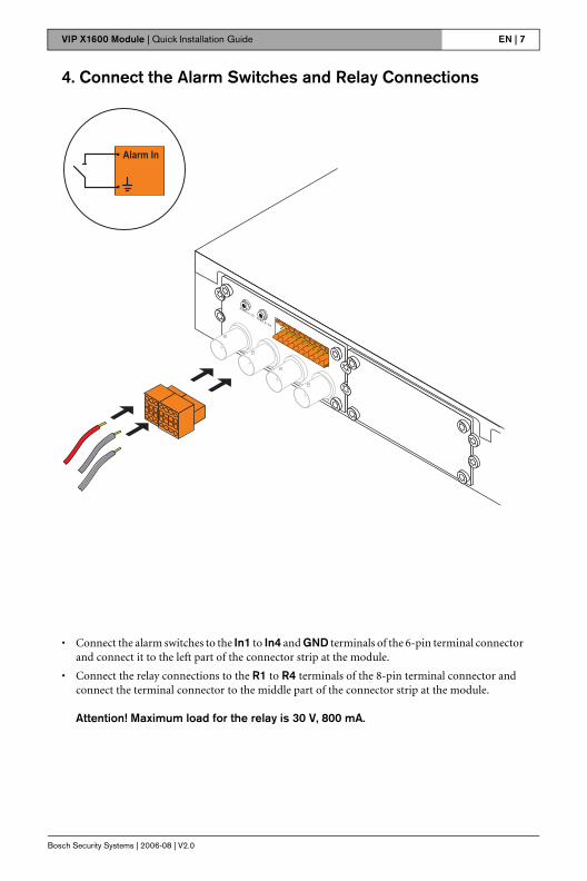
4. Connect the Alarm Switches and Relay Connections
• Connect the alarm switches to the In1 to In4 and GND terminals of the 6-pin terminal connector and connect it to the left part of the connector strip at the module.
• Connect the relay connections to the R1 to R4 terminals of the 8-pin terminal connector and connect the terminal connector to the middle part of the connector strip at the module.
Attention! Maximum load for the relay is 30 V, 800 mA.
EN | 8 Quick Installation Guide | VIP X1600 Module
Bosch Security Systems | 2006-08 | V2.0
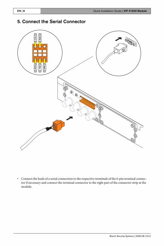
5. Connect the Serial Connector
• Connect the leads of a serial connection to the respective terminals of the 6-pin terminal connec-tor if necessary and connect the terminal connector to the right part of the connector strip at the module.

VIP X1600 Module | Quick Installation Guide EN | 9
Bosch Security Systems | 2006-08 | V2.0
6. Connect the Audio Components (Audio Version Only)
• For Line connections use the Audio In 1 / 2 and Audio In 3 / 4 jacks.
Line In: 9 kOhm typ., 5,5 Vp-p max.
EN | 10 Quick Installation Guide | VIP X1600 Module
Bosch Security Systems | 2006-08 | V2.0
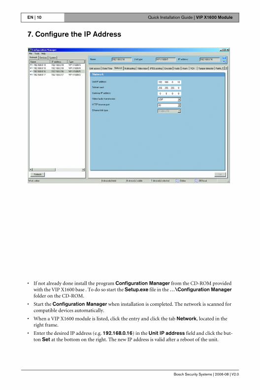
7. Configure the IP Address
• If not already done install the program Configuration Manager from the CD-ROM provided with the VIP X1600 base . To do so start the Setup.exe file in the …\Configuration Manager folder on the CD-ROM.
• Start the Configuration Manager when installation is completed. The network is scanned for compatible devices automatically.
• When a VIP X1600 module is listed, click the entry and click the tab Network, located in the right frame.
• Enter the desired IP address (e.g. 192.168.0.16) in the Unit IP address field and click the but-ton Set at the bottom on the right. The new IP address is valid after a reboot of the unit.

VIP X1600 Module | Quick Installation Guide EN | 11
Bosch Security Systems | 2006-08 | V2.0
8. Test the Configuration
• Launch the Web browser and enter the IP address of the VIP X1600 module as the URL (e.g. http://192.168.0.16) to check that the unit is properly connected to the network.
Note: Set the graphics card of the computer to 16-bit or 32-bit color depth. Otherwise the com-puter cannot display the video images.
• Use the links at the top of the Web pages to navigate.
Bosch Sicherheitssyteme GmbH Bosch Security Systems B.V.Robert-Koch-Straße 100 P.O. Box 8000285521 Ottobrunn 5600 JB EindhovenGermany The Netherlandswww.bosch-sicherheitssysteme.de www.boschsecuritysystems.com
© 2006 Bosch Sicherheitssysteme GmbHSubject to change.VIPX1600M4/0806/QIG_en/3