vip x1/vip x2 – network video...
TRANSCRIPT
VIP X1/VIP X2 – Network video server
Bosch Security Systems | 2006-05 | V2.0
VIP X1/VIP X2 | Quick Installation GuideEN | 2
These instructions "Quick Installation Guide" refer to the units VIP X1 and VIP X2, both in basic and in audio version. The title shows the basic versions of VIP X1 and VIP X2. In the drawings the VIP X1 in audio version is displayed standing for all versions.
Attention
You should always make yourself familiar with the required safety measures in the cor-responding chapter of the user's manual (see CD-ROM supplied). You will find more important details on the installation and on the operation of the unit in the manual. These instructions "Quick Installation Guide" only show the basic installation of a VIP X1 or VIP X2, but they are no substitute for the complete user's manual.
Bosch Security Systems | 2006-05 | V2.0
VIP X1/VIP X2 | Quick Installation Guide EN | 3
Contents of Delivery
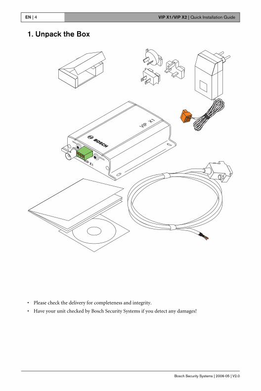
• VIP X1 (or VIP X2) Network Video Server, basic version or audio version
• Power outlet with four primary adapters
• Configuration cable
• CD-ROM
• Quick Installation Guide
Bosch Security Systems | 2006-05 | V2.0
VIP X1/VIP X2 | Quick Installation GuideEN | 4
1. Unpack the Box
• Please check the delivery for completeness and integrity.
• Have your unit checked by Bosch Security Systems if you detect any damages!
Bosch Security Systems | 2006-05 | V2.0
VIP X1/VIP X2 | Quick Installation Guide EN | 5
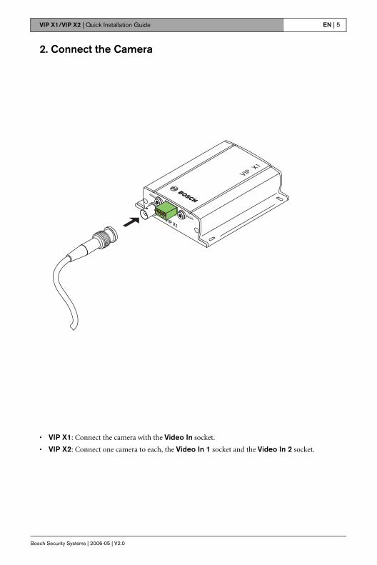
2. Connect the Camera
• VIP X1: Connect the camera with the Video In socket.
• VIP X2: Connect one camera to each, the Video In 1 socket and the Video In 2 socket.
Bosch Security Systems | 2006-05 | V2.0
VIP X1/VIP X2 | Quick Installation GuideEN | 6
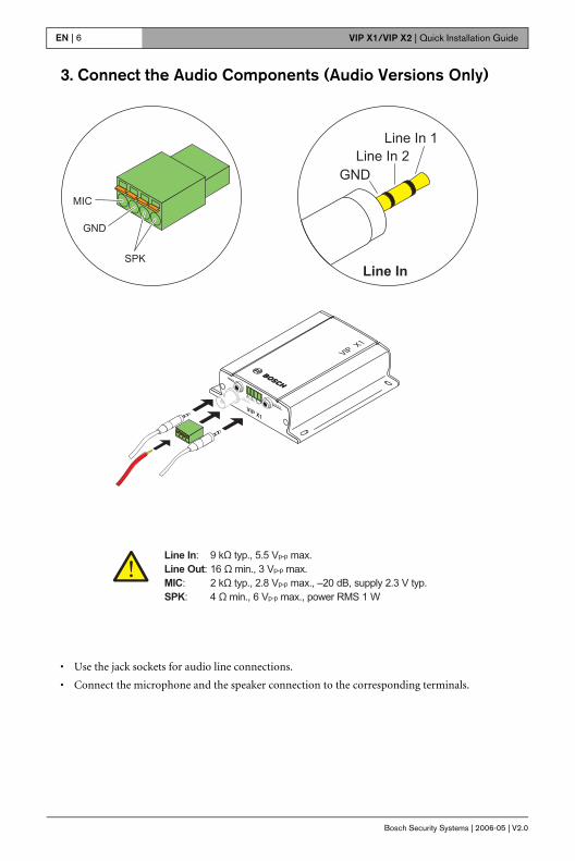
3. Connect the Audio Components (Audio Versions Only)
• Use the jack sockets for audio line connections.
• Connect the microphone and the speaker connection to the corresponding terminals.
Bosch Security Systems | 2006-05 | V2.0
VIP X1/VIP X2 | Quick Installation Guide EN | 7
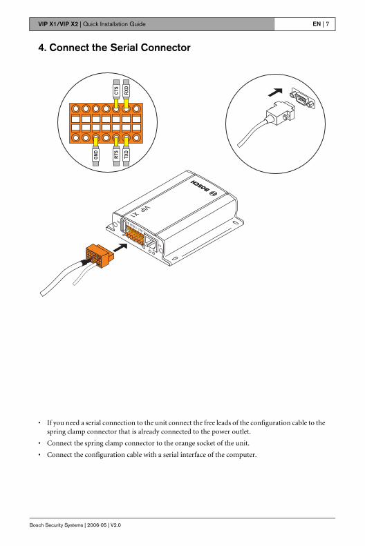
4. Connect the Serial Connector
• If you need a serial connection to the unit connect the free leads of the configuration cable to the spring clamp connector that is already connected to the power outlet.
• Connect the spring clamp connector to the orange socket of the unit.
• Connect the configuration cable with a serial interface of the computer.
Bosch Security Systems | 2006-05 | V2.0
VIP X1/VIP X2 | Quick Installation GuideEN | 8
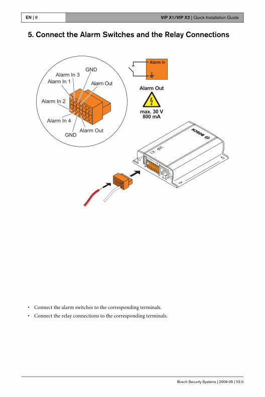
5. Connect the Alarm Switches and the Relay Connections
• Connect the alarm switches to the corresponding terminals.
• Connect the relay connections to the corresponding terminals.
Bosch Security Systems | 2006-05 | V2.0
VIP X1/VIP X2 | Quick Installation Guide EN | 9
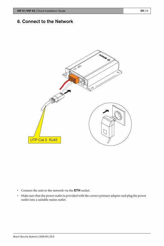
6. Connect to the Network
• Connect the unit to the network via the ETH socket.
• Make sure that the power outlet is provided with the correct primary adapter and plug the power outlet into a suitable mains outlet.
Bosch Security Systems | 2006-05 | V2.0
VIP X1/VIP X2 | Quick Installation GuideEN | 10
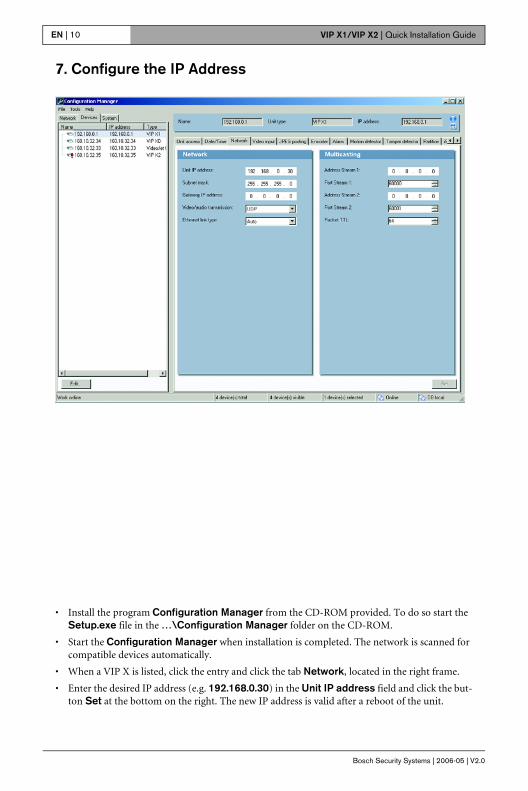
7. Configure the IP Address
• Install the program Configuration Manager from the CD-ROM provided. To do so start the Setup.exe file in the …\Configuration Manager folder on the CD-ROM.
• Start the Configuration Manager when installation is completed. The network is scanned for compatible devices automatically.
• When a VIP X is listed, click the entry and click the tab Network, located in the right frame.
• Enter the desired IP address (e.g. 192.168.0.30) in the Unit IP address field and click the but-ton Set at the bottom on the right. The new IP address is valid after a reboot of the unit.
Bosch Security Systems | 2006-05 | V2.0
VIP X1/VIP X2 | Quick Installation Guide EN | 11
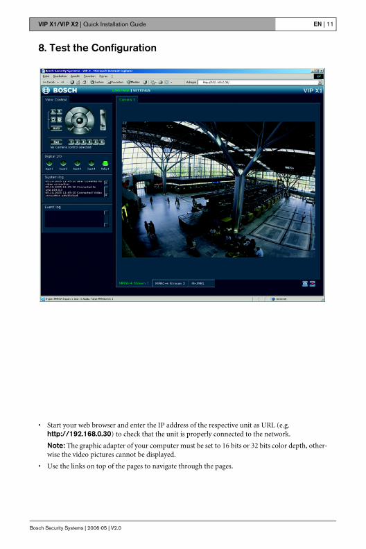
8. Test the Configuration
• Start your web browser and enter the IP address of the respective unit as URL (e.g. http://192.168.0.30) to check that the unit is properly connected to the network.
Note: The graphic adapter of your computer must be set to 16 bits or 32 bits color depth, other-wise the video pictures cannot be displayed.
• Use the links on top of the pages to navigate through the pages.
Bosch Sicherheitssyteme GmbH Bosch Security Systems B.V.Robert-Koch-Straße 100 P.O. Box 8000285521 Ottobrunn 5600 JB EindhovenGermany The Netherlandswww.bosch-sicherheitssysteme.de www.boschsecuritysystems.com
© 2006 Bosch Sicherheitssysteme GmbHSubject to change. Printed in Germany.2501B/0506/QIG_en/3d