viperstud product catalog - cemcosteel.com · a high strength, flat steeldrywall framing system the...
TRANSCRIPT

Effective 5/11/2018 | #VSB5-5/2015
Expanding Your Solutions
ViperStud® Product CatalogInterior Non-Load Bearing Studs and Track

Standing Strong.TM
The Proprietary Steel Framing System That Has Withstood The Test Of Time ...
By providing a lighter, stronger,
more e�cient framing system,
ViperStud® has earned the trust
of industry leaders nationwide.
Made from high-strength steel
and formed with exclusive
VViiperRRiibb ttechhnollogy,
ViperStud® is the �at steel
system that will be here
for the long term,
you can count on that.
ViperStud Drywall Framing System is tested or conforms to these standards:• AISI S100-12 North American Specification
for the Design of Cold-Formed Steel Structural Members, 2012.
• AISI S220-11 North American Standard for Cold-Formed Steel Framing—Non-Structural Members
• ASTM A1003 Standard Specification for Steel Sheet, Carbon, Metallic- and Nonmetallic Coated for Cold-Formed Framing Members
• ASTM C645 Standard Specification for Nonstructural Steel Framing Members
• ASTM A653/A653M Standard Specification for Steel Sheet, Zinc-Coated (Galvanized) or Zinc-Iron Alloy-Coated (Galvannealed) by the Hot-Dip Process
• ASTM C754 Standard Specification for Install-ation of Steel Framing Members to Receive Screw-Attached Gypsum Panel Products
• ASTM E90 Standard Test Method for Laboratory Measurement of Airborne Sound Transmission Loss of Building Partitions and Elements
• ASTM E119 Standard Test Methods for Fire Tests of Building construction and Materials. Fire rated for 1, 2, 3, and 4 hour rated walls.
• ASTM E72 Standard Test Methods of Conducting Strength Tests of Panels for Building Construction
• ASTM C1629 Standard Classification for Abuse-Resistant Nondecorated Interior Gypsum Panel Products and Fiber-Reinforced Cement Panels
ViperStud is listed in the following:• ICC-ES ESR-2620• NYC Department of Buildings MEA 56-08-M,
MEA 56-08-M Vol 2, MEA 235-08-M
Architectural Testing Approved & ICC ES Code Compliant Viper25, Viper20, Viper 18mil, Viper 30mil, and Viper 33mil manufactured by CEMCO received an evaluation report (ESR# 2620) from ICC Evaluation Service (ICC-ES), providing evidence that the ViperStud Drywall Framing System meets code requirements. Building officials, architects, contractors, specifiers, designers and others utilize these Evaluation Reports to provide a basis for using or approving metal framing in construction projects following the International Building Code.
LEED v4 for Building & Design Construction• MR Prerequisite: Construction and Demolition
Waste Management Planning• MR Credit: Construction and Demolition
Waste Management• MR Credit: Building Product Disclosure and
Optimization—Sourcing of Raw Materials, Option 2
• MR Credit: Building Product Disclosure and Optimization—Material Ingredients, Option 1.
• MR Credit: Building Life-Cycle Impact Reduction, Option 4
Recycled Content • Total Recycled Content: 36.9%• Post-Consumer: 19.8%• Pre-Consumer: 14.4%
Code Information ViperStud Drywall Framing has been verified by the following IAS Accredited Test Agencies and/or certified by the Product Evaluation Agencies listed here.
Patents ViperStud Patent #D621,964 ViperTrack Patent #D621,963
IBC/IRC 2012/2015 CompliantViperStud complies with 2015 ICC-ES code compliance certification programs. Please see the full versions of these reports at www.cemcosteel.com.
U.S. Patent Nos. D621,964 and D621,963 are assigned to Ware Industries, Inc. and used by CEMCO under license from Ware Industries, Inc. “ViperStud®,” “ViperTrack®,” and “ViperRib®” are registered trademarks of Ware Industries, Inc. The ViperStud logo and “Standing Strong.™” are trademarks of Ware Industries, Inc. The “ViperStud®,” “ViperTrack®,” “ViperRib®,” and “Standing Strong.™” trademarks are used by CEMCO under license from Ware Industries, Inc. ©2011 Ware Industries, Inc. All rights reserved.
A Track Record You Can Count On, Verified Code Compliant

A High Strength, Flat Steel Drywall Framing SystemThe ViperStud® Drywall Framing System offers all the benefits of conventional flat steel studswith a design that performs even better. The ViperStud® drywall framing system is interchange-
able with conventional framing components. Since ViperStud® is flat steel, it is easy to plumband mark, make minor adjustments and use laser levels. This makes installation the same
as conventional studs. No extra training or special fastenersare required for installation.
Knurl & Rib TechnologyThe stud and track system utilizes a knurled flange and reinforcing ribs along with a flat
stud design. Knurling is the pattern of small ridges formed on the flange to prevent screwsfrom walking. Since knurling is only formed on one side of the steel, the stud stays flat, never
compromising the strength or thickness of the steel.
ViperRib® technology applies a reinforced ribbing over the web and flange of ViperStud.The ribs provide added strength, are lessprone to twist and creating”high-shoulders” when fin-ishing gypsum board.
Knurling Pattern
Flat Steel
ViperRib®
Inside FlangeView
ViperRib® Technologymakes ViperStud stronger & less prone to twist or buckle.
The One-Track SystemWe’ve tested ViperTrack25 extensively with Viper25 and Viper20 studs. Our third-party testing proves that it is not necessary to use the same thickness track as the stud. Nowyou can submit a lighter gauge track with your Viper20 studsand reduce your cost.
• Saves money• Fewer items to inventory• Supported by testing
Not applicable for Impact or Abuse Rated walls. Fire rated walls should be built per specific assembly requirements.
3www.cemcosteel.com
For more information, please contact CEMCO’s Technical Service Department at 800-416-2278.This technical information reflects the most current information available and supersedes anyand all previous publications effective May 11, 2018 #VSB5-5/2015
ViperStud® Drywall Framing System
VIPERSTUD® & VIPERTRACK®

MODEL NO.
DESIGN THICKNESS (in)
MINIMUM THICKNESS (in)
YIELD (ksi) WEB SIZES (in) COATING
1,2FLANGE
(in)RETURN
LIP VIPER25 0.0155 0.0147 50 1-5/8, 2-1/2, 3-5/8, 4, 6 G40 1-1/4 1/4
VIPER 18mil 0.0188 0.0179 33 1-5/8, 2-1/2, 3-5/8, 4, 6 G40 1-1/4 1/4VIPER20 0.0205 0.0195 57 1-5/8, 2-1/2, 3-5/8 G40 1-1/4 1/4VIPER20 0.0220 0.0209 57 4, 6 G40 1-1/4 1/4
VIPER 30mil 0.0312 0.0296 33 1-5/8, 2-1/2, 3-5/8, 4, 6 G40 1-1/4 1/4VIPER 33mil 0.0346 0.0329 33 1-5/8, 2-1/2, 3-5/8, 4, 6 G40 1-1/4 1/4
MODEL NO.
DESIGN THICKNESS (in)
MINIMUM THICKNESS (in)
YIELD (ksi) WEB SIZES (in) COATING
1,2FLANGE
(in) VIPERTRACK25 0.0155 0.0147 50 1-5/8, 2-1/2, 3-5/8, 4, 6 G40 1-1/4
VIPERTRACK 18mil 0.0188 0.0179 33 1-5/8, 2-1/2, 3-5/8, 4, 6 G40 1-1/4VIPERTRACK20 0.0205 0.0195 50 1-5/8, 2-1/2, 3-5/8 G40 1-1/4VIPERTRACK20 0.0220 0.0209 50 4, 6 G40 1-1/4
VIPERTRACK 30mil 0.0312 0.0296 33 1-5/8, 2-1/2, 3-5/8, 4, 6 G40 1-1/4VIPERTRACK 33mil 0.0346 0.0329 33 1-5/8, 2-1/2, 3-5/8, 4, 6 G40 1-1/4
Viper25 (15 mil) is equivalent to conventional 25 gauge (18 mil) studs, and Viper20 (20 & 21 mil) is equivalent to conventional 20 gauge (30 mil). Both Viper25 and Viper20 meet ASTM C645. ASTM C 645 Section 5.1 allows for permissible dimensional thickness variations. Section 8.2 allows for thickness variations and exemptions from minimum section property values, if specified performance requirements are not met. The ViperStud Drywall Framing products meet and exceed these requirements.
Notes: 1. Per ASTM C645 & ASTM A1003 Table 1. 2. G60 and G90 available upon request. 3. Knockout size for 1-5/8" & 2-1/2" stud is 3/4" x 1-3/4".
Knockout size for 3-5/8", 4", and 6" stud is 1-1/2" x 2-1/2".
ViperStud®
ViperTrack®
MODEL NO.DESIGN
THICKNESS (in)
MINIMUM THICKNESS
(in)YIELD (ksi)
COATING 4,5 WEB SIZES (in) 2 LEG
SIZE (in)GAP (in)
LOAD (lb.)
MAX HEIGHT1
5 psf, 16”o.c. VIPERTRACK25 0.0155 0.0147 50 G40 1-5/8, 2-1/2, 3-5/8, 4, 6 2” 1/2” 34 10’-3”
VIPERTRACK18mil 0.0188 0.0179 33 G40 1-5/8, 2-1/2, 3-5/8, 4, 6 2” 1/2” 33 9’ 11”
VIPERTRACK200.0205 0.0195
50 G401-5/8, 2-1/2, 3-5/8 2” 1/2” 68 20’-6”
0.0205 0.0195 2-1/2, 3-5/8 2-1/2” 3/4” 45 13’-8”0.0205 0.0195 2-1/2, 3-5/8 3” 1” 34 10’-3”
VIPERTRACK200.0220 0.0209
50 G404, 6 2” 1/2” 78 23’-8”
0.0220 0.0209 4, 6 2-1/2” 3/4” 52 15”-9”0.0220 0.0209 4, 6 3” 1” 39 11’-10”
VIPERTRACK30mil
0.0312 0.029633 G40
1-5/8, 2-1/2, 3-5/8, 4, 6 2” 1/2” 91 27’-6”0.0312 0.0296 2-1/2, 3-5/8, 4, 6 2-1/2” 3/4” 61 18’-4”0.0312 0.0296 2-1/2, 3-5/8, 4, 6 3” 1” 45 13’-9”
VIPERTRACK 33mil
0.0346 0.032933 G40
1-5/8, 2-1/2, 3-5/8, 4, 6 2” 1/2” 112 33’-10”0.0346 0.0329 2-1/2, 3-5/8, 4, 6 2-1/2” 3/4” 75 22’-7”0.0346 0.0329 2-1/2, 3-5/8, 4, 6 3” 1” 56 16’-11”
Notes:1. Max wall height based on stud spacing of
16” o.c. & 5 PSF lateral load. 2. 1-5/8” deep leg track available with max 2” leg.3. Wall studs are not fastened to deep leg track.4. G60, G90 available upon request.5. Per ASTM C645 & ASTM A1003, Table 1
DEEP LEG DEFLECTION TRACKDeflection track can be required at the top of a wall to allow for anticipation downward movement of the primary structure. A gap is provided between the end of the stud and track to accommodate this movement. The studs are not fastened to the track to allow movement up or down. The bridging is required within 12" from the top to keep the stud in place and provide rotational restraint. The leg of the track must be long enough to provide the required gap, bearing surface for the studs and allow for construction tolerances.
Studs are secured by one of the following methods:
A. CR channel and BRC Clip. 12" down from the stud end.
B. Attaching flat strap at each side of the stud flange. 12" down from the stud end.
C. Attaching 2 screws at each leg of the deep leg track, near the stud flanges. (Total 4 screws)
ViperStud® Drywall Framing System
PHYSICAL PROPERTIES
www.cemcosteel.com
For more information, please contact CEMCO’s Technical Service Department at 800-416-2278.This technical information reflects the most current information available and supersedes anyand all previous publications effective May 11, 2018 #VSB5-5/2015
4

Notes: 1. Section properties are in accordance with AISI S100-12. Viper 25 and Viper20 section properties are based on testing. Allowable moment (Ma) is calculated in accordance with Chapter F of AISI S100-12 specification.
2. Nominal moment for Viper 18 mil, Viper 30 mil, and Viper 33 mil conventional studs are based on calculations in accordance with AISI S100-12. Allowable moments (Ma) can be calculated with a 1.67 safety factor. 3. Section properties are in accordance with AISI S100-12 with S2-09 and AISI S220-11.
4. Web depth-to-thickness ratio exceeds 200. 5. Web depth-to-thickness ration exceeds 260. 6. Viperstud is considered fully braced when unbraced length is less than listed Lu.7. KΦ assumed to be zero for distortional buckling moments.
MODEL NO.
GAUGE(mils) MEMBER
DESIGN (in)
MIN. (in)
YIELD (ksi)
WEIGHT(lb/ft)
GROSS PROPERTIES EFFECTIVEPROPERTIES MOMENTS
CRITICAL UNBRACEDLENGTH (in)
AREA (in2)
Ix(in4)
Rx (in)
Iy (in4)
Ry (in)
Ixd (in4)
Sx (in3)
Allowable Moment
Ma (in-k)
Local Buckling Nominal Moment 2
Viper
Mnl (in-k)
DistortionalBuckling Nominal Moment2
Viper
Mnd (in-k)
Nominal Moment
for Conventional
Studs 3
Mn (in-k)
VIPER25 25EQ(15)
162VS125-15 0.0155 0.0147 50 0.24 0.071 0.032 0.671 0.015 0.461 0.032 0.024 0.66 1.42 1.20 1.02 (18MIL) 25.1250VS125-15 0.0155 0.0147 50 0.29 0.085 0.084 .0998 0.017 0.452 0.090 0.042 1.17 2.72 2.12 1.72 (18MIL) 24.8362VS125-154 0.0155 0.0147 50 0.35 0.102 0.199 1.390 0.019 0.435 0.205 0.058 1.60 3.48 2.90 2.47 (18MIL) 24.5400VS125-154 0.0155 0.0147 50 0.37 0.108 0.250 1.520 0.020 0.429 0.255 0.061 1.69 3.99 3.06 2.74 (18MIL) 24.4600VS125-155 0.0155 0.0147 50 0.47 0.139 0.659 2.180 0.022 0.397 0.628 0.085 2.36 5.90 4.27 4.13 (18MIL) 23.7
VIPER 18mil
25(18)
162VS125-18 0.0188 0.0179 33 0.28 0.069 0.039 0.684 0.018 0.461 0.037 0.035 0.68 1.14 1.23 1.02 (18MIL) 30.70250VS125-18 0.0188 0.0179 33 0.34 0.099 0.102 1.015 0.020 0.454 0.098 0.065 1.29 2.15 1.95 1.72 (18MIL) 29.70362VS125-18 0.0188 0.0179 33 0.41 0.120 0.241 1.414 0.023 0.437 0.237 0.084 1.65 2.76 2.89 2.47 (18MIL) 29.90400VS125-184 0.0188 0.0179 33 0.43 0.127 0.303 1.542 0.024 0.431 0.299 0.093 1.83 3.06 3.20 2.74 (18MIL) 29.80
VIPER20 20EQ(20/21)
162VS125-20 0.0205 0.0195 57 0.32 0.093 0.042 0.673 0.020 0.459 0.050 0.038 1.18 2.74 2.14 1.99 (30MIL) 23.4250VS125-20 0.0205 0.0195 57 0.38 0.111 0.111 1.000 0.023 0.451 0.129 0.065 2.05 4.50 3.71 3.49 (30MIL) 23.1362VS125-20 0.0205 0.0195 57 0.45 0.134 0.261 1.400 0.025 0.433 0.298 0.090 2.85 6.10 5.15 5.14 (30MIL) 22.8400VS125-21 0.0220 0.0209 57 0.52 0.152 0.352 1.520 0.028 0.426 0.377 0.117 3.69 8.02 6.67 5.74 (30MIL) 22.7600VS125-215 0.0220 0.0209 57 0.67 0.196 0.929 2.180 0.030 0.394 0.869 0.161 5.06 11.20 9.16 9.00 (30MIL) 22.0
VIPER 30mil
20(30)
162VS125-30 0.0312 0.0296 33 0.46 0.135 0.062 0.688 0.028 0.455 0.062 0.067 1.32 2.21 2.38 1.99 (30MIL) 30.8250VS125-30 0.0312 0.0296 33 0.55 0.161 0.166 1.020 0.032 .0448 0.163 .0120 2.31 3.96 3.86 3.49 (30MIL) 30.1362VS125-30 0.0312 0.0296 33 0.67 0.197 0.391 1.410 0.037 0.431 0.385 0.172 3.39 5.67 5.85 5.14 (30MIL) 29.7400VS125-30 0.0312 0.0296 33 0.71 0.209 0.493 1.540 0.038 0.425 0.486 0.191 3.78 6.31 6.52 5.74 (30MIL) 29.6600VS125-30 0.0312 0.0296 33 0.92 0.271 1.310 2.190 0.042 0.392 1.230 0.341 5.95 11.30 9.93 9.00 (30MIL) 28.7
VIPER 33mil
20(33)
162VS125-33 0.0346 0.0329 33 0.50 0.147 0.069 0.683 0.030 0.453 0.068 0.077 1.53 2.55 2.71 2.29 (33MIL) 30.8250VS125-33 0.0346 0.0329 33 0.61 0.178 0.183 1.010 0.036 0.447 0.181 0.137 2.65 4.53 4.42 4.02 (33MIL) 30.1362VS125-33 0.0346 0.0329 33 0.75 0.220 0.432 1.400 0.040 0.429 0.428 0.201 3.96 6.62 6.75 6.00 (33MIL) 29.7400VS125-33 0.0346 0.0329 33 0.78 0.230 0.544 1.540 0.041 0.424 0.539 0.224 4.42 7.38 7.53 6.70 (33MIL) 29.5600VS125-33 0.0346 0.0329 33 1.02 0.301 1.440 2.190 0.046 0.391 1.390 0.400 6.93 13.20 11.60 10.55 (33MIL) 28.6
VIPERSTUD®
PRODUCT NAME
LEG SIZE (in)
WEIGHT (lb/ft)
DESIGN (in)
MIN.(in)
YIELD (ksi)
GROSS PROPERTIES EFFECTIVE PROPERTIES TORSIONAL PROPERTIES
AREA (in2)
Ix(in4)
Sx(in)
Rx(in4)
Iy(in)
Sy(in4)
Ry(in3)
Ixd(in4)
Sxe(in3)
Ma(in-k)
Xo(in)
Jx103
(in4)Cw(in6)
Ro(in) ß
VIPERTRACK 1.25" LEG162VT125-15 1.25 0.22 0.0155 0.0147 50 0.064 0.035 0.040 0.736 0.011 0.013 0.412 0.022 0.018 0.53 -0.877 0.005 0.006 1.22 0.480250VT125-15 1.25 0.26 0.0155 0.0147 50 0.078 0.086 0.066 1.050 0.012 0.013 0.400 0.054 0.027 0.80 -0.768 0.006 0.015 1.36 0.683362VT125-155 1.25 0.32 0.0155 0.0147 50 0.095 0.197 0.105 1.440 0.014 0.014 0.381 0.155 0.039 1.15 -0.665 0.008 0.035 1.63 0.833400VT125-155 1.25 0.34 0.0155 0.0147 50 0.101 0.247 0.120 1.560 0.014 0.014 0.374 0.141 0.043 1.27 -0.638 0.008 0.043 1.73 0.864600VT125-156 1.25 0.45 0.0155 0.0147 50 0.132 0.642 0.210 2.210 0.015 0.015 0.342 0.325 0.063 1.90 -0.523 0.011 0.109 2.29 0.948162VT125-18 1.25 0.26 0.0188 0.0179 33 0.077 0.042 0.048 0.733 0.013 0.0149 0.411 0.030 0.025 0.50 -0.878 0.009 0.007 1.215 0.478250VT125-18 1.25 0.32 0.0188 0.0179 33 0.094 0.105 0.080 1.057 0.015 0.0160 0.399 0.079 0.046 0.90 -0.766 0.011 0.018 1.366 0.685362VT125-18 1.25 0.39 0.0188 0.0179 33 0.115 0.240 0.127 1.442 0.017 0.0168 0.380 0.192 0.066 1.30 -0.664 0.014 0.042 1.632 0.835400VT125-18 1.25 0.42 0.0188 0.0179 33 0.122 0.300 0.145 1.566 0.017 0.0170 0.374 0.244 0.072 1.43 -0.636 0.014 0.053 1.731 0.865
600VT125-186, 7 1.25 0.54 0.0188 0.0179 33 0.160 0.779 0.254 2.208 0.019 0.0176 0.342 - - - -0.521 0.019 0.132 2.294 0.948162VT125-20 1.25 0.29 0.0205 0.0195 50 0.085 0.046 0.052 0.737 0.014 0.017 0.411 0.031 0.027 0.79 -0.874 0.012 0.008 1.22 0.483250VT125-20 1.25 0.35 0.0205 0.0195 50 0.103 0.114 0.087 1.060 0.016 0.018 0.399 0.081 0.045 1.33 -0.766 0.014 0.020 1.36 0.685362VT125-20 1.25 0.43 0.0205 0.0195 50 0.123 0.261 0.139 1.440 0.018 0.018 0.380 0.179 0.064 1.92 -0.663 0.018 0.046 1.63 0.835400VT125-21 1.25 0.49 0.0220 0.0209 50 0.143 0.351 0.170 1.570 0.02 0.020 0.373 0.246 0.081 2.41 -0.635 0.023 0.061 1.73 0.865600VT125-216 1.25 0.64 0.0220 0.0209 50 0.187 0.910 0.297 2.210 0.022 0.021 0.341 0.557 0.117 3.49 -0.520 0.030 0.154 2.29 0.949162VT125-30 1.25 0.44 0.0312 0.0296 33 0.129 0.071 0.080 0.741 0.022 0.025 0.409 0.056 0.051 1.00 -0.868 0.042 0.012 1.21 0.488250VT125-30 1.25 0.53 0.0312 0.0296 33 0.156 0.175 0.132 1.060 0.025 0.027 0.397 0.142 0.090 1.77 -0.760 0.051 0.030 1.36 0.689362VT125-30 1.25 0.65 0.0312 0.0296 33 0.192 0.399 0.211 1.440 0.027 0.028 0.378 0.331 0.152 3.00 -0.658 0.062 0.069 1.63 0.837400VT125-30 1.25 0.69 0.0312 0.0296 33 0.203 0.499 0.240 1.570 0.028 0.028 0.371 0.417 0.176 3.47 -0.631 0.066 0.086 1.73 0.867600VT125-30 1.25 0.90 0.0312 0.0296 33 0.266 1.300 0.421 2.210 0.031 0.029 0.339 1.030 0.250 4.94 -0.517 0.086 0.216 2.29 0.949162VT125-33 1.25 0.49 0.0346 0.0329 33 0.143 0.079 0.088 0.742 0.024 0.028 0.408 0.064 0.059 1.16 -0.866 0.057 0.013 1.21 0.489250VT125-33 1.25 0.59 0.0346 0.0329 33 0.174 0.195 0.146 1.060 0.027 0.029 0.396 0.162 0.103 2.04 -0.758 0.069 0.033 1.36 0.690362VT125-33 1.25 0.72 0.0346 0.0329 33 0.212 0.443 0.234 1.440 0.03 0.031 0.377 0.375 0.173 3.43 -0.657 0.085 0.077 1.63 0.838400VT125-33 1.25 0.77 0.0346 0.0329 33 0.225 0.554 0.266 1.570 0.031 0.031 0.370 0.473 0.200 3.95 -0.629 0.090 0.096 1.73 0.868600VT125-33 1.25 1.00 0.0346 0.0329 33 0.295 1.440 0.467 2.210 0.034 0.032 0.339 1.190 0.298 5.89 -0.516 0.118 0.239 2.29 0.949
www.cemcosteel.com
For more information, please contact CEMCO’s Technical Service Department at 800-416-2278.This technical information reflects the most current information available and supersedes anyand all previous publications effective May 11, 2018 #VSB5-5/2015
ViperStud® Drywall Framing System
SECTION PROPERTIES
5
VIPERTRACK®

ViperStud® Drywall Framing System
DEEP LEG VIPERTRACK SECTION PROPERTIES
VIPERTRACK®
PRODUCT NAME
LEG SIZE (in)
WEIGHT (lb/ft)
DESIGN (in)
MIN. (in)
YIELD (ksi)
GROSS PROPERTIES EFFECTIVE PROPERTIES TORSIONAL PROPERTIESAREA
(in2)Ix
(in4)Sx(in)
Rx(in4)
Iy(in)
Sy(in4)
Ry(in3)
Ixd(in4)
Sxe(in3)
Ma(in-k)
Xo(in)
Jx103
(in4)Cw(in6)
Ro(in) ß
VIPERTRACK 2.00" LEG162VT200-15 2.00 0.30 0.0155 0.0147 50 0.087 0.052 0.060 0.773 0.038 0.030 0.663 0.025 0.017 0.50 -1.57 0.007 0.021 1.87 0.295250VT200-15 2.00 0.34 0.0155 0.0147 50 0.101 0.126 0.096 1.117 0.044 0.032 0.662 0.060 0.026 0.79 -1.43 0.008 0.054 1.93 0.453362VT200-155 2.00 0.40 0.0155 0.0147 50 0.118 0.278 0.148 1.533 0.050 0.034 0.648 0.127 0.039 1.16 -1.28 0.009 0.122 2.10 0.629400VT200-155 2.00 0.42 0.0155 0.0147 50 0.124 0.345 0.167 1.667 0.051 0.034 0.642 0.155 0.043 1.28 -1.24 0.010 0.152 2.17 0.676600VT200-156 2.00 0.53 0.0155 0.0147 50 0.155 0.859 0.281 2.353 0.057 0.036 0.608 0.357 0.065 1.93 -1.06 0.012 0.384 2.65 0.841250VT200-187 2.00 0.42 0.0188 0.0179 33 0.122 0.154 0.116 1.121 0.053 0.0383 0.661 - - - -1.43 0.014 0.066 1.93 0.455362VT200-187 2.00 0.49 0.0188 0.0179 33 0.144 0.339 0.180 1.537 0.060 0.0407 0.647 - - - -1.28 0.017 0.149 2.10 0.630400VT200-187 2.00 0.51 0.0188 0.0179 33 0.151 0.420 0.203 1.670 0.062 0.0412 0.642 - - - -1.24 0.018 0.186 2.17 0.677
600VT200-186, 7 2.00 0.64 0.0188 0.0179 33 0.188 1.039 0.339 2.350 0.069 0.0434 0.607 - - - -1.06 0.022 0.464 2.65 0.841162VT200-20 2.00 0.39 0.0205 0.0195 50 0.116 0.069 0.079 0.775 0.051 0.039 0.662 0.036 0.027 0.91 -1.57 0.016 0.028 1.87 0.296250VT200-20 2.00 0.45 0.0205 0.0195 50 0.134 0.167 0.127 1.118 0.058 0.042 0.661 0.091 0.041 1.41 -1.42 0.019 0.071 1.93 0.454362VT200-20 2.00 0.53 0.0205 0.0195 50 0.157 0.369 0.196 1.534 0.066 0.045 0.647 0.190 0.060 2.06 -1.28 0.022 0.161 2.10 0.630400VT200-21 2.00 0.60 0.0220 0.0209 50 0.176 0.491 0.237 1.670 0.072 0.048 0.641 0.261 0.076 2.59 -1.23 0.028 0.216 2.17 0.677600VT200-216 2.00 0.75 0.0220 0.0209 50 0.220 1.221 0.398 2.350 0.081 0.051 0.606 0.602 0.115 3.91 -1.05 0.036 0.544 2.65 0.842162VT200-30 2.00 0.60 0.0312 0.0296 33 0.176 0.107 0.120 0.779 0.077 0.060 0.660 0.069 0.055 1.09 -1.56 0.057 0.043 1.87 0.299250VT200-30 2.00 0.69 0.0312 0.0296 33 0.203 0.256 0.193 1.120 0.088 0.064 0.659 0.174 0.098 1.94 -1.42 0.066 0.108 1.92 0.457362VT200-30 2.00 0.81 0.0312 0.0296 33 0.238 0.563 0.298 1.540 0.099 0.068 0.645 0.400 0.167 3.29 -1.27 0.077 0.246 2.10 0.633400VT200-30 2.00 0.85 0.0312 0.0296 33 0.250 0.698 0.336 1.670 0.102 0.068 0.639 0.502 0.188 3.71 -1.23 0.081 0.306 2.17 0.680600VT200-30 2.00 1.06 0.0312 0.0296 33 0.312 1.735 0.564 2.360 0.114 0.072 0.605 1.270 0.276 5.45 -1.05 0.101 0.769 2.65 0.843162VT200-33 2.00 0.66 0.0346 0.0329 33 0.195 0.119 0.133 0.780 0.085 0.066 0.660 0.080 0.064 1.27 -1.56 0.078 0.048 1.87 0.300250VT200-33 2.00 0.77 0.0346 0.0329 33 0.225 0.284 0.214 1.120 0.098 0.071 0.658 0.199 0.113 2.23 -1.42 0.090 0.120 1.92 0.458362VT200-33 2.00 0.90 0.0346 0.0329 33 0.264 0.626 0.330 1.540 0.110 0.075 0.644 0.455 0.191 3.76 -1.27 0.105 0.272 2.10 0.634400VT200-33 2.00 0.94 0.0346 0.0329 33 0.277 0.775 0.373 1.670 0.113 0.076 0.638 0.570 0.220 4.34 -1.23 0.111 0.340 2.17 0.680600VT200-33 2.00 1.18 0.0346 0.0329 33 0.347 1.930 0.625 2.360 0.126 0.080 0.604 1.480 0.338 6.69 -1.05 0.138 0.852 2.65 0.844
VIPERTRACK 2.50" LEG162VT250-20 2.50 0.46 0.0205 0.0195 50 0.136 0.085 0.097 0.790 0.092 0.059 0.823 0.039 0.026 0.88 -2.05 0.019 0.052 2.35 0.237250VT250-20 2.50 0.52 0.0205 0.0195 50 0.154 0.202 0.153 1.150 0.106 0.064 0.830 0.094 0.041 1.40 -1.89 0.022 0.130 2.36 0.360362VT250-20 2.50 0.60 0.0205 0.0195 50 0.177 0.440 0.234 0.158 0.120 0.068 0.822 0.200 0.060 2.06 -1.71 0.025 0.295 2.47 0.519400VT250-21 2.50 0.68 0.0220 0.0209 50 0.198 0.584 0.282 1.720 0.132 0.074 0.817 0.274 0.076 2.58 -1.66 0.032 0.395 2.53 0.566600VT250-216 2.50 0.82 0.0220 0.0209 50 0.242 1.430 0.465 2.430 0.145 0.078 0.785 0.630 0.115 3.92 -1.45 0.039 0.989 2.93 0.757162VT250-30 2.50 0.71 0.0312 0.0296 33 0.207 0.131 0.147 0.794 0.140 0.090 0.822 0.076 0.057 1.13 -2.04 0.067 0.080 2.34 0.239250VT250-30 2.50 0.80 0.0312 0.0296 33 0.234 0.310 0.233 1.150 0.161 0.097 0.828 0.190 0.102 2.01 -1.88 0.076 0.199 2.35 0.363362VT250-30 2.50 0.92 0.0312 0.0296 33 0.270 0.673 0.356 1.580 0.181 0.102 0.820 0.437 0.167 3.30 -1.71 0.088 0.449 2.47 0.521400VT250-30 2.50 0.96 0.0312 0.0296 33 0.281 0.831 0.400 1.720 0.187 0.104 0.816 0.548 0.185 3.66 -1.66 0.091 0.560 2.52 0.568600VT250-30 2.50 1.17 0.0312 0.0296 33 0.344 2.030 0.659 2.430 0.211 0.110 0.784 1.330 0.275 5.43 -1.44 0.112 1.400 2.93 0.758162VT250-33 2.50 0.78 0.0346 0.0329 33 0.230 0.145 0.163 0.796 0.155 0.100 0.821 0.088 0.066 1.31 -2.04 0.092 0.089 2.34 0.239250VT250-33 2.50 0.89 0.0346 0.0329 33 0.260 0.344 0.258 1.150 0.178 0.107 0.827 0.218 0.117 2.32 -1.88 0.104 0.221 2.35 0.363362VT250-33 2.50 1.02 0.0346 0.0329 33 0.299 0.748 0.395 1.580 0.201 0.114 0.820 0.498 0.198 3.92 -1.71 0.119 0.498 2.47 0.522400VT250-33 2.50 1.06 0.0346 0.0329 33 0.312 0.923 0.443 1.720 0.207 0.115 0.815 0.623 0.226 4.46 -1.66 0.124 0.621 2.52 0.569600VT250-33 2.50 1.30 0.0346 0.0329 33 0.381 2.250 0.730 2.430 0.234 0.122 0.783 1.580 0.336 6.64 -1.44 0.152 1.550 2.93 0.759
VIPERTRACK 3.00" LEG162VT300-20 3.00 0.53 0.0205 0.0195 50 0.157 0.100 0.114 0.801 0.151 0.083 0.981 0.041 0.028 0.95 -2.53 0.022 0.087 2.83 0.200250VT300-20 3.00 0.59 0.0205 0.0195 50 0.175 0.237 0.180 1.170 0.173 0.089 0.995 0.098 0.041 1.39 -2.36 0.025 0.216 2.81 0.298362VT300-20 3.00 0.67 0.0205 0.0195 50 0.198 0.512 0.272 1.610 0.195 0.095 0.994 0.207 0.060 2.05 -2.17 0.028 0.484 2.87 0.433400VT300-21 3.00 0.75 0.0220 0.0209 50 0.220 0.677 0.327 1.750 0.216 0.103 0.991 0.284 0.076 2.58 -2.11 0.036 0.647 2.92 0.477600VT300-216 3.00 0.90 0.0220 0.0209 50 0.264 1.630 0.532 2.490 0.245 0.109 0.964 0.653 0.115 3.92 -1.86 0.043 1.610 3.25 0.673162VT300-30 3.00 0.81 0.0312 0.0296 33 0.238 0.155 0.174 0.805 0.229 0.126 0.980 0.081 0.058 1.15 -2.53 0.077 0.134 2.83 0.201250VT300-30 3.00 0.90 0.0312 0.0296 33 0.266 0.363 0.274 1.170 0.262 0.135 0.993 0.204 0.104 2.06 -2.35 0.086 0.329 2.80 0.299362VT300-30 3.00 1.02 0.0312 0.0296 33 0.301 0.783 0.414 1.610 0.296 0.144 0.992 0.469 0.165 3.25 -2.16 0.098 0.738 2.87 0.435400VT300-30 3.00 1.06 0.0312 0.0296 33 0.312 0.964 0.464 1.760 0.306 0.146 0.989 0.587 0.183 3.61 -2.10 0.101 0.918 2.91 0.479600VT300-30 3.00 1.28 0.0312 0.0296 33 0.375 2.320 0.754 2.490 0.347 0.155 0.962 1.380 0.274 5.41 -1.85 0.122 2.290 3.25 0.674162VT300-33 3.00 0.90 0.0346 0.0329 33 0.264 0.172 0.192 0.807 0.254 0.139 0.979 0.094 0.068 1.34 -2.52 0.105 0.149 2.82 0.202250VT300-33 3.00 1.00 0.0346 0.0329 33 0.295 0.404 0.303 1.170 0.290 0.150 0.993 0.234 0.120 2.38 -2.35 0.118 0.366 2.80 0.300362VT300-33 3.00 1.14 0.0346 0.0329 33 0.334 0.869 0.459 1.620 0.328 0.159 0.992 0.535 0.200 3.96 -2.16 0.133 0.819 2.87 0.436400VT300-33 3.00 1.18 0.0346 0.0329 33 0.347 1.070 0.514 1.760 0.339 0.162 0.988 0.669 0.223 4.40 -2.10 0.138 1.020 2.91 0.480600VT300-33 3.00 1.41 0.0346 0.0329 33 0.416 2.580 0.836 2.490 0.384 0.171 0.961 1.640 0.334 6.60 -1.85 0.166 2.540 3.25 0.675
Notes: 1. Section properties are in accordance with AISI S100-12. 2. Cold-work of forming is not included. 3. The effective moment of inertia fpr deflection is calculated based on AISI S100-12
procedure 1 for serviceability determination.
4. The center line bend radius is greater than 2 times the design thickness or 3/32. 5. Web-to-thickness ration exceeds 200. 6. Web-to-thickness ratio exceeds 260.7. Flange-width-to-thickness-ratio exceeds 60.
www.cemcosteel.com
For more information, please contact CEMCO’s Technical Service Department at 800-416-2278.This technical information reflects the most current information available and supersedes anyand all previous publications effective May 11, 2018 #VSB5-5/2015
6

MODELNO. DEPTH
GAUGE(mil.) MEMBER
DESIGN (in)
MIN. (in)
YIELD (ksi)
SPACING O.C.(in)
5 PSF 7.5 PSF 10 PSF
L/120 L/240 L/360 L/120 L/240 L/360 L/120 L/240 L/360
VIPER25
1-5/8” 25 EQ(15)
162VS125-15 0.0155 0.0147 50 12 13’-9” 11’-4” 9’-10” 12’-0” 9’-11” 8’-3” 10’-11” 8’-10” --162VS125-15 0.0155 0.0147 50 16 12’-6” 10’-4” 8’-8” 10’-11” 8’-10” -- 9’-11” 7’-11” --162VS125-15 0.0155 0.0147 50 24 10’-11” 8’-10” -- 9’-5” -- -- 8’-2” -- --
2-1/2” 25 EQ(15)
250VS125-15 0.0155 0.0147 50 12 17’-3” 14’-5” 12’-9” 15’-0” 12’-7” 11’-1” 13’-8” 11’-6” 10’-1”250VS125-15 0.0155 0.0147 50 16 15’-8” 13’-1” 11’-7” 13’-8” 11’-6” 10’-1” 12’-3” 10’-5” 8’-9”250VS125-15 0.0155 0.0147 50 24 13’-8” 11’-6” 10’-1” 11’-6” 10’-0” 8’-2” 10’-0” 8’-8” --
3-5/8” 25 EQ(15)
362VS125-15 0.0155 0.0147 50 12 20’-10” 17’-3” 15’-2” 18’-2” 15’-1” 13’-3” 15’-10” 13’-9” 12’-0”362VS125-15 0.0155 0.0147 50 16 18’-11” 15’-9” 13’-9” 15’-10” 13’-9” 12’-0” 13’-9” 12’-6” 10’-11”362VS125-15 0.0155 0.0147 50 24 15’-10” 13’-9” 12’-0” 12’-11” 12’-0” 10’-6” 11’-3” 10’-11” 9’-6”
4” 25 EQ(15)
400VS125-15 0.0155 0.0147 50 12 22’-1” 18’-3” 16’-3” 19’-3” 15’-11” 14’-2” 16’-8” 14’-6” 12’-11”400VS125-15 0.0155 0.0147 50 16 20’-1” 16’-7” 14’-9” 16’-8” 14’-6” 12’-11” 14’-5” 13’-2” 11’-9”400VS125-15 0.0155 0.0147 50 24 16’-8” 14’-6” 12’-11” 13’-7” 12’-8” 11’-3” 11’-0” 11’-6” 10’-1”
6” 25 EQ(15)
600VS125-15 0.0155 0.0147 50 12 24’-8” 23’-9” 21’-1” 22’-3” 20’-9” 18’-5” 20’-0” 18’-10” 16’-9”600VS125-15 0.0155 0.0147 50 16 22’-11” 21’-7” 19’-2” 20’-0” 18’-10” 16’-9” 17’-5” 17’-2” 15’-3”600VS125-15 0.0155 0.0147 50 24 20’-1” 18’-10” 16’-9” 16’-5” 16’-5” 14’-8” 14’-2” 14’-2” 13’-0”
VIPER 18MIL
1-5/8” 25(18)
162VS125-18 0.0188 0.0179 33 12 12’-10” 10’-7” 9’-4” 11’-3” 9’-3” 8’-2” 10’-3” 8’-5” --162VS125-18 0.0188 0.0179 33 16 11’-9” 9’-8” 8’-6” 10’-3” 8’-5” -- 9’-4” -- --162VS125-18 0.0188 0.0179 33 24 10’-3” 8’-5” -- 8’-11” -- -- 8’-2” -- --
2-1/2” 25(18)
250VS125-18 0.0188 0.0179 33 12 17’-5” 14’-5” 12’-7” 14’-7” F 12’-7” 11’-0” 12’-8” F 11’-5” 9’-8”250VS125-18 0.0188 0.0179 33 16 15’-6” F 13’-1” 11’-6” 12’-8” F 11’-5” 9’-8” 11’-0” F 10’-3” 8’-6”250VS125-18 0.0188 0.0179 33 24 12’-8” F 11’-5” 9’-8” 10’-4” F 9’-8” 8’-1” 8’-11” F 8’-6” --
3-5/8” 25(18)
362VS125-18 0.0188 0.0179 33 12 21’-7” F 17’-7” 15’-4” 17’-8” F 15’-4” 13’-5” 15’-3” F 13’-11” 12’-2”362VS125-18 0.0188 0.0179 33 16 18’-9” F 15’-11” 13’-11” 15’-3” F 13’-11” 12’-2” 13’-3” F 12’-8” 11’-0”362VS125-18 0.0188 0.0179 33 24 15’-3” F 13’-11” 12’-2” 12’-6” F 12’-2” 10’-6” 10’-10” F 10’-10” F 9’-5”
4” 25(18)
400VS125-18 0.0188 0.0179 33 12 20’-6” F 18’-5” 16’-3” 16’-9” F 16’-1” 14’-2” 14’-6” F 14’-6” F 12’-11”400VS125-18 0.0188 0.0179 33 16 17’-9” F 16’-9” 14’-9” 14’-6” F 14’-6” F 12’-11” 12’-7” F 12’-7” F 11’-9”400VS125-18 0.0188 0.0179 33 24 14’-6” F 14’-6” F 12’-11” 11’-10” F 11”-10” F 11’-2” 10’-3” F 10’-3” F 9’-11”
6” 25(18)
600VS125-18 0.0188 0.0179 33 12 25’-5” F 24’-9” 21’-8” 20’-9” F 20’-9” F 18’-11” 18’-0” F 18’-0” F 17’-2”600VS125-18 0.0188 0.0179 33 16 22’-0” F 22’-0” F 19’-8” 18’-0” F 18’-0” F 17’-2” 15’-7” F 15’-7” F 15’-7” F600VS125-18 0.0188 0.0179 33 24 18’-0” F 18’-0” F 17’-2” 14’-8” F 14’-8” F 14’-8” F 12’-9” F 12’-9” F 12’-9” F
VIPER20
1-5/8” 20EQ(20)
162VS125-20 0.0205 0.0195 57 12 14’-3” 11’-3” 9’-10” 12’-5” 9’-10” 8’-5” 11’-3” 8’-10” --162VS125-20 0.0205 0.0195 57 16 12’-11” 10’-3” 8’-10” 11’-3” 8’-10” -- 10’-3” 7’-11” --162VS125-20 0.0205 0.0195 57 24 11’-3” 8’-10” -- 9’-10” -- -- 8’-10” -- --
2-1/2” 20EQ(20)
250VS125-20 0.0205 0.0195 57 12 17’-11” 14’-10” 13’-2” 15’-8” 13’-0” 11’-6” 14’-3” 11’-10” 10’-5”250VS125-20 0.0205 0.0195 57 16 16’-4” 13’-6” 12’-0” 12’-3” 11’-10” 10’-5” 12’-11” 10’-9” 9’-4”250VS125-20 0.0205 0.0195 57 24 14’-3” 11’-10” 10’-5” 12’-5” 10’-4” 8’-9” 11’-3” 9’-2” --
3-5/8” 20EQ(20)
362VS125-20 0.0205 0.0195 57 12 21’-10” 17’-11” 15’-9” 19’-1” 15’-8” 13’-9” 17’-4” 14’-3” 12’-6”362VS125-20 0.0205 0.0195 57 16 19’-10” 16’-4” 14’-4” 17’-4” 14’-3” 12’-6” 15’-4” 12’-11” 11’-4”362VS125-20 0.0205 0.0195 57 24 17’-4” 14’-3” 12’-6” 14’-6” 12’-5” 10’-11” 12’-7” 11’-4” 9’-11”
4” 20EQ(21)
400VS125-21 0.0220 0.0209 57 12 24’-0” 19’-1” 16’-8” 21’-0”` 16’-8” 14’-7” 19’-1” 15’-2” 13’-3”400VS125-21 0.0220 0.0209 57 16 21’-10” 17’-4” 15’-2” 19’-1” 15’-2” 13’-3” 17’-4” 13’-9” 12’-0”400VS125-21 0.0220 0.0209 57 24 19’-1” 15’-2” 13’-3” 16’-8” 13’-3” 11’-7” 14’-11” 12’-0” 10’-5”
6” 20EQ(21)
600VS125-21 0.0220 0.0209 57 12 29’-1” 25’-7” 22’-6” 25’-10” 22’-4” 19’-8” 23’-8” 20’-4” 17’-11”600VS125-21 0.0220 0.0209 57 16 26’-9” 23’-3” 20’-6” 23’-8” 20’-4” 17’-11” 21’-9” 18’-6” 16’-3”600VS125-21 0.0220 0.0209 57 24 23’-8” 20’-4” 17’-11” 20’-11” 17’-9” 15’-7” 18’-2” 16’-2” 14’-2”
VIPER30MIL
1-5/8” 20(30)
162VS125-30 0.0312 0.0296 33 12 14’-7” 11’-6” 10’-0” 12’-9” 10’-0” 8’-6” 11’-7” 8’-11” --162VS125-30 0.0312 0.0296 33 16 13’-3” 10’-5” 8’-11” 11’-7” 8’-11” -- 10’-6” 7’-10” --162VS125-30 0.0312 0.0296 33 24 11’-7” 8’-11” -- 10’-1” -- -- 8’-10” -- --
2-1/2” 20(30)
250VS125-30 0.0312 0.0296 33 12 18’-9” 14’-10” 13’-0” 16’-4” 13’-0” 11’-4” 14’-10” 11’-10” 10’-4”250VS125-30 0.0312 0.0296 33 16 17’-0” 13’-6” 11’-10” 14’-10” 11’-10” 10’-4” 13’-6” 10’-9” 9’-3”250VS125-30 0.0312 0.0296 33 24 14’-10” 11’-10” 10’-4” 12’-9” 10’-4” 8’-10” 11’-0” 9’-3” --
3-5/8” 20(30)
362VS125-30 0.0312 0.0296 33 12 23’-3” 18’-6” 16’-2” 20’-4” 16’-2” 14’-1” 18’-6” 14’-8” 12’-10”362VS125-30 0.0312 0.0296 33 16 21’-2” 16’-9” 14’-8” 18’-6” 14’-8” 12’-10” 16’-4” 13’-4” 11’-6”362VS125-30 0.0312 0.0296 33 24 18’-6” 14’-8” 12’-10” 15’-4” 12’-10” 11’-0” 13’-4” 11’-6” 9’-11”
4” 20(30)
400VS125-30 0.0312 0.0296 33 12 25’-2” 20’-0” 17’-6” 22’-0” 17’-6” 15’-3” 19’-5” 15’-11” 13’-10”400VS125-30 0.0312 0.0296 33 16 22’-11” 18’-2” 15’-11” 19’-5” 15’-11” 13’-10” 16’-10” 14’-5” 12’-7”400VS125-30 0.0312 0.0296 33 24 19’-5” 15’-11” 13’-10” 15’-10” 13’-10” 12’-1” 13’-9” 12’-7” 10’-11”
6” 20(30)
600VS125-30 0.0312 0.0296 33 12 31’-10” 26’-9” 23’-4” 26’-0” 23’-4” 20’-5” 22’-6” 21’-3” 18’-6”600VS125-30 0.0312 0.0296 33 16 27’-7” 24’-3” 21’-3” 22’-6” 21’-3” 18’-6” 19’-6” 19’-3” 16’-10”600VS125-30 0.0312 0.0296 33 24 22’-6” 21’-3” 18’-6” 18’-5” 18’-5” 16’-2” 15’-11” 15’-11” 14’-8”
VIPER33 MIL
1-5/8” 20(33)
162VS125-33 0.0346 0.0329 33 12 14’-11” 11’-10” 10’-4” 13’-0” 10’-4” 8’-10” 11’-10” 9’-4” --162VS125-33 0.0346 0.0329 33 16 13’-6” 10’-9” 9’-4” 11’-10” 9’-4” -- 10’-9” 8’-4” --162VS125-33 0.0346 0.0329 33 24 11’-10” 9’-4” -- 10’-4” -- -- 9’-4” -- --
2-1/2” 20(33)
250VS125-33 0.0346 0.0329 33 12 19’-4” 15’-4” 13’-5” 16’-10” 13’-5” 11’-8” 15’-4” 12’-2” 10’-8”250VS125-33 0.0346 0.0329 33 16 17’-7” 13’-11” 12’-2” 15’-4” 12’-2” 10’-8” 13’-11” 11’-0” 9’-8”250VS125-33 0.0346 0.0329 33 24 15’-4” 12’-2” 10’-8” 13’-5” 10’-8” 9’-2” 12’-0” 9’-8” --
3-5/8” 20(33)
362VS125-33 0.0346 0.0329 33 12 23’-10” 18’-11” 16’-6” 20’-10” 16’-6” 14’-5” 18’-11” 15’-0” 13’-1”362VS125-33 0.0346 0.0329 33 16 21’-8” 17’-2” 15’-0” 18’-11” 15’-0” 13’-1” 17’-2” 13’-8” 11’-0”362VS125-33 0.0346 0.0329 33 24 18’-11” 15’-0” 13’-1” 16’-6” 13’-1” 11’-4” 14’-4” 11’-10” 10’-3”
4” 20(33)
400VS125-33 0.0346 0.0329 33 12 25’-8” 20’-4” 17’-10” 22’-5” 17’-10” 15’-7” 20’-4” 16’-2” 14’-1”400VS125-33 0.0346 0.0329 33 16 23’-4” 18’-6” 16’-2” 20’-4” 16’-2” 14’-2” 18’-4” 14’-8” 12’-10”400VS125-33 0.0346 0.0329 33 24 20’-4” 16’-2” 14’-1” 17’-3” 14’-2” 12’-4” 15’-0” 12’-10” 11’-2”
6” 20(33)
600VS125-33 0.0346 0.0329 33 12 34’-5” 27’-7” 24’-1” 28’-1” 24’-1” 21’-1” 24’-4” 21’-11” 19’-2”600VS125-33 0.0346 0.0329 33 16 29’-10” 25’-1” 21’-11” 24’-4” 21’-11” 19’-2” 21’-1” 19’-11” 17’-5”600VS125-33 0.0346 0.0329 33 24 24’-4” 21’-11” 19’-2” 19’-11” 19’-2” 16’-9” 17’-2” 17’-2” 15’-2”
Notes:1. Viper composite limiting heights are based on testing in accordance with ICC-ES
acceptance criteria AC86-2012.2. No screws are required between stud and track, except as required by ASTM C754.
Composite heights are based on using standard top track. Screw fastening of stud to track is not required. Mechanically fastening of gypsum panel to the stud and track is required.
3. Viper composite limiting heights based on a single layer of 5/8” type X gypsum board applied vertically to both sides of the wall over full height. 5/8” Type X wallboard from the following manufacturers are acceptable: USG, National, Georgia-Pacific, Temple Inland, CertainTeed, American, & LaFarge.
ViperStud® Drywall Framing System
COMPOSITE LIMITING HEIGHTS – 5/8" TYPE X3
7
MODELNO. DEPTH
GAUGE(mil.) MEMBER
YIELD (ksi)
SPACING O.C. (in)
5 PSF 7.5 PSF 10 PSF
L/120 L/240 L/360 L/120 L/240 L/360 L/120 L/240 L/360
VIPER25
1-5/8” 25 EQ(15)
162VS125-15 50 12 9’-5” F 7’-6” 6’-7” 7’-8” F 6’-7” -- 6’-7” F 6’-0” --162VS125-15 50 16 8’-1” F 6’-10” 6’-0” 6’-7” F 6’-0” -- -- -- --162VS125-15 50 24 6’-7” F 6’-0” -- -- -- -- -- -- --
2-1/2” 25 EQ(15)
250VS125-15 50 12 12’-6” F 10’-7” 9’-2” 10’-2” F 9’-2” 8’-1” 8’-10” F 8’-5” 7’-4”250VS125-15 50 16 10’-10”F 9’-7” 8’-5” 8’-10” F 8’-5” 7’-4” 7’-8” F 7’-7” 6’-8”250VS125-15 50 24 8’-10” F 8’-5” 7’-4” 7’-1” W 7’-1” W 6’-5” -- -- --
3-5/8” 25 EQ(15)
362VS125-156 50 12 14’-7” F 13’-11” 12’-1” 11’-11” F 11’-11”F 10’-7” 10’-4” F 10’-4” F 9’-7”362VS125-156 50 16 12’-8” F 12’-7” 11’-0” 10’-4” 10’-4” F 9’-7” 9’-0” F 9’-0” F 8’-10”362VS125-156 50 24 10’-4” F 10’-4” F 9’-7” 8’-5” F 8’-5” F 8’-5” 6’-7” W 6’-7” W 6’-7”W
4” 25 EQ(15)
400VS125-156 50 12 15-0” F 15’-0” 13’-1” 12’-4” F 12’-4” F 11’-5” 10’-7” F 10’-7” F 10’-5”400VS125-156 50 16 13’-0” F 13’-0” F 11’-11” 10’-7” F 10’-7” F 10’-5” 9’-2” F 9’-2” F 9’-2”F400VS125-156 50 24 10’-7” F 10’-7” F 10’-5” 8’-6” W 8’-6” W 8’-6” W 6’-5” W 6’-5” W 6’-5”W
6” 25 EQ(15)
600VS125-15 50 12 17’-8” F 17’-8” F 17’-7” 14’-1” W 14’-1” W 14’-1”W 10’-7” W 10’-7” W 10’-7”W600VS125-15 50 16 15’-5” F 15’-5” F 15’-5” F 10’-7” W 10’-7” W 10’-7” W 7’-11” W 7’-11” W 7’-11” W600VS125-15 50 24 10’-7” W 10’-7” W 10’-7” W 7’-0” W 7’-0”W 7’-0”W -- -- --
VIPER 18MIL
1-5/8” 25(18)
162VS125-18 33 12 9’ 6” 7’ 10” 6’ 10” 7’ 9” 6’ 10” 5’ 11” 6’ 8” 6’ 2” 5’ 5”162VS125-18 33 16 8’ 3” 7’ 1” 6’ 2” 6’ 8” 6’ 2” 5’ 5” 5’ 10” 5’ 7” 4’ 11”162VS125-18 33 24 6’ 8” 6’ 2” 5’ 5” 5’ 6” 5’ 5” 4’ 8” 4’ 9” 4’ 9” 4’ 3”
2-1/2” 25(18)
250VS125-18 33 12 12’ 5” 10’ 10” 9’ 5” 10’ 1” 9’ 5” 8’ 3” 8’ 9” 8’ 7” 7’ 6”250VS125-18 33 16 10’ 9” 9’ 10” 8’ 7” 8’ 9” 8’ 7” 7’ 6” 7’ 7” 7’ 7” 6’ 9”250VS125-18 33 24 8’ 9” 8’ 7” 7’ 6” 6’ 11” 6’ 11” 6’ 6” 5’ 2” 5’ 2” 5’ 2”
3-5/8” 25(18)
362VS125-18 33 12 14’ 10” 14’ 6” 12’ 8” 12’ 1” 12’ 1” 11’ 1” 9’ 8” 9’ 8” 9’ 8”362VS125-18 33 16 12’ 10” 12’ 10” 11’ 6” 9’ 8” 9’ 8” 9’ 8” 7’ 3” 7’ 3” 7’ 3”362VS125-18 33 24 9’ 8” 9’ 8” 9’ 8” 6’ 5” 6’ 5” 6’ 5” 4’ 10” 4’ 10” 4’ 10”
4” 25(18)
400VS125-186 33 12 15’ 7” 15’ 7” 13’ 9” 12’ 9” 12’ 9” 12’ 0” 11’ 0” 11’ 0” 11’ 0”400VS125-186 33 16 13’ 6” 13’ 6” 12’ 5” 11’ 0” 11’ 0” 10’ 11” 9’ 6” 9’ 6” 9’ 6”400VS125-186 33 24 11’ 0” 11’ 0” 10’ 11” 9’ 0” 9’ 0” 9’ 0” 7’ 9” 7’ 9” 7’ 9”
6” 25(18)
600VS125-18 33 12 - - - - - - - - -600VS125-18 33 16 - - - - - - - - -600VS125-18 33 24 - - - - - - - - -
VIPER20
1-5/8” 20EQ(20)
162VS125-20 57 12 10’-11” 8’-8” 7’-7” 9’-6” 7’-7” 6’-7” 8’-8” 6’-11” 6’-0”162VS125-20 57 16 9’-11” 7’-11” 6’-11” 8’-8” 6’-11” 6’-0” 7’-8”F 6’-4” --162VS125-20 57 24 8’-8” 6’-11” 6’-0” 7’-2” F 6’-0” -- 6’-4” F -- --
2-1/2” 20EQ(20)
250VS125-20 57 12 15’-0” 11’-11” 10’-5” 13’-1” 10’-5” 9’-1” 11’-8” F 9’-6” 8’-4”250VS125-20 57 16 13’-7” 10’-10” 9’-6” 11’-8” F 9’-6” 8’-4” 10’-1” F 8’-7” 7’-6”250VS125-20 57 24 11’-8” F 9’-6” 8’-4” 9’-6” F 8’-4” 7’-2” 8’-4” F 7’-6” 6’-7”
3-5/8” 20EQ(20)
362VS125-20 57 12 19’-6” F 15’-10” 13’-10” 15’-11” F 13’-10” 12’-0” 13’-10” F 12’-6” 10’-11”362VS125-20 57 16 16’-11” F 14’-4” 12’-6” 13’-10” F 12’-6” 10’-11” 11’-11” F 11’-5” 9’-11”362VS125-20 57 24 13’-10” F 12’-6” 10’-11” 11’-2” F 10’-11” 9’-6” 9’-8” F 9’-8” F 8’-8”
4” 20EQ(21)
400VS125-21 57 12 21’-6” 17’-0” 14’-11” 18’-1” F 14’-11” 13’-0” 15’-8” F 13’-6” 11’-10”400VS125-21 57 16 19’-2” F 15’-6” 13’-6” 15’-8” F 13’-6” 11’-10” 13’-7” F 12’-4” 10’-8”400VS125-21 57 24 15’-8” F 13’-6” 11’-10” 12’-10” F 11’-10” 10’-4” 11’-1” F 10’-8” 9’-5”
6” 20EQ(21)
600VS125-21 57 12 26’-0” F 22’-6” 19’-8” 21’-2” F 19’-8” 17’-2” 18’-5” F 17’-11” 15’-7”600VS125-21 57 16 22’-6” F 20’-5” 17’-11” 18’-5” F 17’-11” 15’-7” 15’-11” F 15’-11” F 14’-2”600VS125-21 57 24 18’-5” F 17’-11” 15’-7” 15’-0” F 15’-0” F 13’-7” 12’-1”W 12’-1”W 12’-1”W
VIPER 30MIL
1-5/8” 20(30)
162VS125-30 33 12 11’-8” 9’-4” 8’-1” 10’-2” 8’-1” 7’-1” 9’-4” 7’-5” 6’-6”162VS125-30 33 16 10’-8” 8’-6” 7’-5” 9’-4” 7’-5” 6’-6” 8’-1” F 6’-8” --162VS125-30 33 24 9’-4” 7’-5” 6’-6” 7’-8” F 6’-6” -- 6’-7” F -- --
2-1/2” 20(30)
250VS125-30 33 12 16’-2” 12’-11” 11’-4” 14’-2” 11’-4” 9’-10” 12’-5” F 10’-2” 8’-11”250VS125-30 33 16 14’-8” 11’-8” 10’-2” 12’-5” F 10’-2” 8’-11” 10’-8” F 9’-4” 8’-1”250VS125-30 33 24 12’-5” F 10’-2” 8’-11” 10’-1” F 8’-11” 7’-10” 8’-10” F 8’-1” 7’-1”
3-5/8” 20(30)
362VS125-30 33 12 21’-4” F 17’-2” 15’-0” 17’-5” F 15’-0” 13’-1” 15’-0” F 13’-7” 11’-11”362VS125-30 33 16 18’-5” F 15’-7” 13’-7” 15’-0” F 13’-7” 11’-11” 13’-0” F 12’-5” 10’-10”362VS125-30 33 24 15’-0” F 13’-7” 11’-11” 12’-4” F 11’-11” 10’-5” 10’-7” F 10’-7” F 9’-5”
4” 20(30)
400VS125-30 33 12 22’-6” F 18’-6” 16’-2” 18’-4” F 16’-2” 14’-1” 15’-11” F 14’-8” 12’-11”400VS125-30 33 16 19’-5” F 16’-10” 14’-8” 15’-11” F 14’-8” 12’-11” 13’-8” F 13’-5” 11’-8”400VS125-30 33 24 15’-11” F 14’-8” 12’-11” 13’-0” F 12’-11” 11’-2” 11’-2” F 11’-2” F 10’-2”
6” 20(30)
600VS125-30 33 12 28’-2” F 25’-4” 22’-1” 23’-0” F 22’-1” 19’-4” 19’-11” F 19’-11” F 17’-6”600VS125-30 33 16 24’-5” F 23’-0” 20’-1” 19’-11” F 19’-11” F 17’-6” 17’-2” F 17’-2” F 15’-11”600VS125-30 33 24 19’-11” F 19’-11” F 17’-6” 16’-4” F 16’-4” F 15’-4” 12’-5” W 12’-5” W 12’-5”W
VIPER 33 MIL
1-5/8” 20(33)
162VS125-33 33 12 12’-1” 9’-7” 8’-5” 10’-7” 8’-5” 7’-4” 9’-7” 7’-7” 6’-8”162VS125-33 33 16 11’-0” 8’-8” 7’-7” 9’-7” 7’-7” 6’-8” 8’-8” F 6’-11” 6’-1”162VS125-33 33 24 9’-7” 7’-7” 6’-8” 8’-2” F 6’-8” -- 7’-1” F 6’-1” --
2-1/2” 20(33)
250VS125-33 33 12 16’-10” 13’-4” 11’-7” 14’-8” 11’-7” 10’-2” 13’-4” F 10’-7” 9’-2”250VS125-33 33 16 15’-4” 12’-1” 10’-7” 13’-4” F 10’-7” 9’-2” 11’-6” F 9’-7” 8’-5”250VS125-33 33 24 13’-4” F 10’-7” 9’-2” 10’-10” F 9’-2” 8’-1” 9’-5” F 8’-5” 7’-4”
3-5/8” 20(33)
362VS125-33 33 12 22’-5” 17’-10” 15’-6” 18’-10” 15’-6” 13’-7” 16’-4” F 14’-1” 12’-4”362VS125-33 33 16 19’-11” F 16’-1” 14’-1” 16’-4” F 14’-1” 12’-4” 14’-1” F 12’-10” 11’-2”362VS125-33 33 24 16’-4” F 14’-1” 12’-4” 13’-4” F 12’-4” 10’-10” 11’-6” F 11’-2” 9’-10”
4” 20(33)
400VS125-33 33 12 24’-2” 19’-2” 16’-10” 19’-10” F 16’-10” 14’-7” 17’-2” F 15’-2” 13’-4”400VS125-33 33 16 21’-0” F 17’-5” 15’-2” 17’-2” F 15’-2” 13’-4” 14’-11” F 13’-10” 12’-1”400VS125-33 33 24 17’-2” F 15’-2” 13’-4” 14’-0” F 13’-4” 11’-7” 12’-1” F 12’-1” 10’-7”
6” 20(33)
600VS125-33 33 12 30’-5” F 26’-4” 23’-0” 24’-10” F 23’-0” 20’-1” 21’-6” F 20’-11” 18’-2”600VS125-33 33 16 26’-4” F 23’-11” 20’-11” 21’-6” F 20’-11” 18’-2” 18’-7” F 18’-7” F 16’-7”600VS125-33 33 24 21’-6” F 20’-11” 18’-2” 17’-6” F 17’-6” F 15’-11” 15’-2” F 15’-2” F 14’-6”
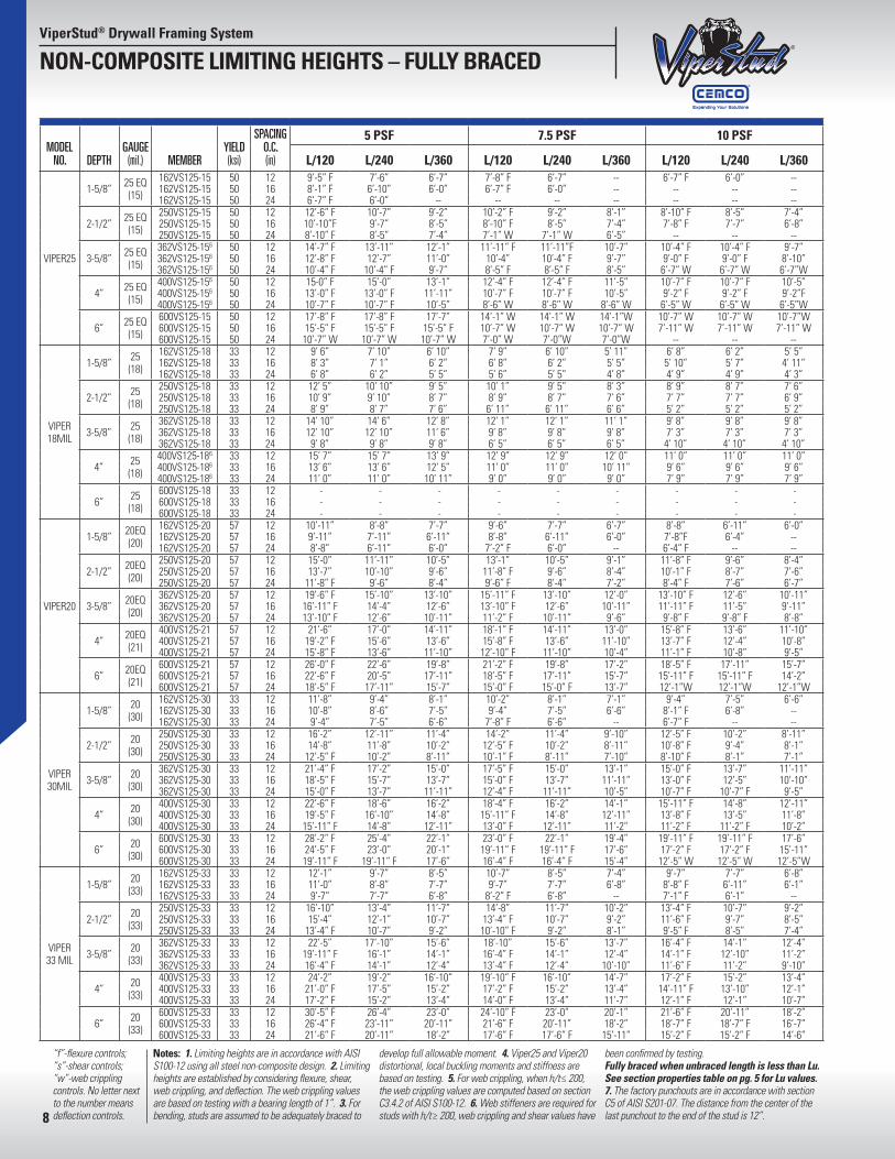
“f”-flexure controls; “s”-shear controls; “w”-web crippling controls. No letter next to the number means deflection controls.
Notes: 1. Limiting heights are in accordance with AISI S100-12 using all steel non-composite design. 2. Limiting heights are established by considering flexure, shear, web crippling, and deflection. The web crippling values are based on testing with a bearing length of 1”. 3. For bending, studs are assumed to be adequately braced to
develop full allowable moment. 4. Viper25 and Viper20 distortional, local buckling moments and stiffness are based on testing. 5. For web crippling, when h/t≤ 200, the web crippling values are computed based on section C3.4.2 of AISI S100-12. 6. Web stiffeners are required for studs with h/t≥ 200, web crippling and shear values have
been confirmed by testing. Fully braced when unbraced length is less than Lu. See section properties table on pg. 5 for Lu values. 7. The factory punchouts are in accordance with section C5 of AISI S201-07. The distance from the center of the last punchout to the end of the stud is 12”.
ViperStud® Drywall Framing System
NON-COMPOSITE LIMITING HEIGHTS – FULLY BRACED
8
MODELNO. DEPTH
GAUGE(mil.) MEMBER
DESIGN (in)
MIN.(in)
YIELD (ksi)
SPACING O.C. (in)
5 PSF 7.5 PSF 10 PSF
L/120 L/240 L/360 L/120 L/240 L/360 L/120 L/240 L/360
VIPER25
1-5/8” 25 EQ(15)
162VS125-15 0.0155 0.0147 50 12 8’-8” F 7’-6” 6’-7” 7’-1”F 6’-7” -- 6’-1” F 6’-0” --162VS125-15 0.0155 0.0147 50 16 7’-6” F 6’-10” 6’-0” 6’-1”F 6’-0” -- -- -- --162VS125-15 0.0155 0.0147 50 24 6’-1” F 6’-0” -- -- -- -- -- -- --
2-1/2” 25 EQ(15)
250VS125-15 0.0155 0.0147 50 12 11’-10” F 10’-7” 9’-2” 9’-7”F 9’-2” 8’-1” 8’-5” F 8’-5” F 7’-4”250VS125-15 0.0155 0.0147 50 16 10’-2” F 9’-7” 8’-5” 8’-5”F 8’-5”F 7’-4” 7’-2” F 7’-2” F 6’-8”250VS125-15 0.0155 0.0147 50 24 8’-5” F 8’-5”F 7’-4” 6’-8”W 6’-8”W 6’-5” -- -- --
3-5/8” 25 EQ(15)
362VS125-156 0.0155 0.0147 50 12 13’-2” F 13’-2”F 12’-1” 10’-10”F 10’-10” F 10’-7” 9’-4”F 9’-4” F 9’-4” F362VS125-156 0.0155 0.0147 50 16 11’-5” F 11’-5”F 11’-0” 9’-4”F 9’-4” F 9’-4” F 7’-10” W 7’-10” W 7’-10”W362VS125-156 0.0155 0.0147 50 24 9’-4” F 9’-4”F 9’-4”F 6’-11”W 6’-11”W 6’-11”W -- -- --
4” 25 EQ(15)
400VS125-156 0.0155 0.0147 50 12 13’-10” F 13’-10”F 13’-1” 11’-4”F 11’-4”F 11’-4” F 9’-10” F 9’-10” F 9’-10” F400VS125-156 0.0155 0.0147 50 16 12’-0” F 12’-0”F 11’-11” 9’-10”F 9’-10” F 9’-10” F 7’-5” W 7’-5” W 7’-5” W400VS125-156 0.0155 0.0147 50 24 9’-10” F 9’-10”F 9’-10”F 6’-6”W 6’-6” W 6’-6” W -- -- --
6” 25 EQ(15)
600VS125-15 0.0155 0.0147 50 12 14’-1” W 14’-1”W 14’-1”W 9’-5”W 9’-5” W 9’-5” W 7’-1” W 7’-1” W 7’-1” W600VS125-15 0.0155 0.0147 50 16 10’-7” W 10’-7”W 10’-7”W 7’-1”W 7’-1” W 7’-1” W -- -- --600VS125-15 0.0155 0.0147 50 24 7’-1” W 7’-1”W 7’-1”W -- -- -- -- -- --
VIPER 18MIL
1-5/8” 25(18)
162VS125-18 0.0188 0.0179 33 12 8’ 11” 7’ 10” 6’ 10” 7’ 4” 6’ 10” 5’ 11” 6’ 4” 6’ 2” 5’ 5”162VS125-18 0.0188 0.0179 33 16 7’ 9” 7’ 1” 6’ 2” 6’ 4” 6’ 2” 5’ 5” 5’ 6” 5’ 6” 4’ 11”162VS125-18 0.0188 0.0179 33 24 6’ 4” 6’ 2” 5’ 5” 5’ 2” 5’ 2” 4’ 8” 4’ 6” 4’ 6” 4’ 3”
2-1/2” 25(18)
250VS125-18 0.0188 0.0179 33 12 12’ 1” 10’ 10” 9’ 5” 9’ 11” 9’ 5” 8’ 3” 8’ 7” 8’ 7” 7’ 6”250VS125-18 0.0188 0.0179 33 16 10’ 6” 9’ 10” 8’ 7” 8’ 7” 8’ 7” 7’ 6” 7’ 5” 7’ 5” 6’ 9”250VS125-18 0.0188 0.0179 33 24 8’ 7” 8’ 7” 7’ 6” 6’ 11” 6’ 11” 6’ 6” 5’ 2” 5’ 2” 5’ 2”
3-5/8” 25(18)
362VS125-18 0.0188 0.0179 33 12 15’ 1” 14’ 6” 12’ 8” 12’ 4” 12’ 4” 11’ 1” 9’ 8” 9’ 8” 9’ 8”362VS125-18 0.0188 0.0179 33 16 13’ 1” 13’ 1” 11’ 6” 9’ 8” 9’ 8” 9’ 8” 7’ 3” 7’ 3” 7’ 3”362VS125-18 0.0188 0.0179 33 24 9’ 8” 9’ 8” 9’ 8” 6’ 5” 6’ 5” 6’ 5” 4’ 10” 4’ 10” 4’ 10”
4” 25(18)
400VS125-186 0.0188 0.0179 33 12 15’ 11” 15’ 8” 13’ 8” 13’ 0” 13’ 0” 12’ 10” 11’ 3” 11’ 3” 10’ 10”400VS125-186 0.0188 0.0179 33 16 13’ 9” 13’ 9” 12’ 5” 12’ 5” 11’ 3” 10’ 10” 9’ 9” 9’ 9” 9’ 9”400VS125-186 0.0188 0.0179 33 24 11’ 3” 11’ 3” 10’ 10” 10’ 10” 9’ 2” 9’ 2” 7’ 11” 7’ 11” 7’ 11”
6” 25(18)
600VS125-18 0.0188 0.0179 33 12 - - - - - - - - -600VS125-18 0.0188 0.0179 33 16 - - - - - - - - -600VS125-18 0.0188 0.0179 33 24 - - - - - - - - -
VIPER20
1-5/8” 20EQ(20)
162VS125-20 0.0205 0.0195 57 12 10’-7” F 8’-8” 7’-7” 8’-7” F 7’-7” 6’-7” 7’-6” F 6’-11” 6’-0”162VS125-20 0.0205 0.0195 57 16 9’-2” F 7’-11” 6’-11” 7’-6” F 6’-11” 6’-0” 6’-6” F 6’-4” --162VS125-20 0.0205 0.0195 57 24 7’-6” F 6’-11” 6’-0” 6’-1” F 6’-0” -- -- -- --
2-1/2” 20EQ(20)
250VS125-20 0.0205 0.0195 57 12 14’-4” F 11’-11” 10’-5” 11’-8” F 10’-5” 9’-1” 10’-1” F 9’-6” 8’-4”250VS125-20 0.0205 0.0195 57 16 12’-5” F 10’-10” 9’-6” 10’-1” F 9’-6” 8’-4” 8’-10” F 8’-7” 7’-6”250VS125-20 0.0205 0.0195 57 24 10’-1” F 9’-6” 8’-4” 8’-4” F 8’-4” 7’-2” 7’-2” F 7’-2” F 6’-7”
3-5/8” 20EQ(20)
362VS125-20 0.0205 0.0195 57 12 16’-2” F 15’-10” 13’-10” 13’-2” F 13’-2” F 12’-0” 11’-5” F 11’-5” F 10’-11”362VS125-20 0.0205 0.0195 57 16 14’-0” F 14’-0” F 12’-6” 11’-5” F 11’-5” F 10’-11” 9’-11” F 9’-11” F 9’-11” F362VS125-20 0.0205 0.0195 57 24 11’-5” F 11’-5” F 10’-11” 9’-4” F 9’-4” F 9’-4” F 8’-1” F 8’-1” F 8’-1” F
4” 20EQ(21)
400VS125-21 0.0220 0.0209 57 12 17’-10” F 17’-0” 14’-11” 14’-7” F 14’-7” F 13’-0” 12’-7” F 12’-7” F 11’-10”400VS125-21 0.0220 0.0209 57 16 15’-6” F 15’-6” F 13’-6” 12’-7” F 12’-7” F 11’-10” 10’-11” F 10’-11” F 10’-8”400VS125-21 0.0220 0.0209 57 24 12’-7” F 12’-7” F 11’-10” 10’-4” F 10’-4” F 10’-4” F 8’-11” F 8’-11” F 8’-11” F
6” 20EQ(21)
600VS125-21 0.0220 0.0209 57 12 23’-1” F 22’-6” 19’-8” 18’-11” F 18’-11” F 17’-2” 16-5” F 16’-5” F 15’-7”600VS125-21 0.0220 0.0209 57 16 20’-0” F 20’-0” F 17’-11” 16’-5” F 16’-5” F 15’-7” 12’-10”W 12’-10”W 12’-10W600VS125-21 0.0220 0.0209 57 24 16’-5” F 16’-5” F 15’-7” 11’-5” W 11’-5” W 11’-5”W 8’-7” W 8’-7” W 8’-7”W
VIPER 30MIL
1-5/8” 20(30)
162VS125-30 0.0312 0.0296 33 12 11’-10” 9’-4” 8’-2” 10’-4” 8’-2” 7’-1” 8’-11” F 7’-5” 6’-6”162VS125-30 0.0312 0.0296 33 16 10’-8” 8-6” 7’-5” 8’-11” F 7’-5” 6’-6” 7’-8” F 6’-8” --162VS125-30 0.0312 0.0296 33 24 8’-11” F 7’-5” 6’-6” 7’-4” F 6’-6” -- 6’-4” F -- --
2-1/2” 20(30)
250VS125-30 0.0312 0.0296 33 12 16’-4” 12’-11” 11’-4” 13’-7” F 11’-4” 9’-11” 11’-10” F 10’-4” 9’-0”250VS125-30 0.0312 0.0296 33 16 14’-5” F 11’-8” 10’-4” 11’-10” F 10’-4” 9’-0” 10’-2” F 9’-4” 8’-1”250VS125-30 0.0312 0.0296 33 24 11’-10” F 10’-4” 9’-0” 9’-7” F 9’-0” 7’-10” 8’-4” F 8’-1” 7’-1”
3-5/8” 20(30)
362VS125-30 0.0312 0.0296 33 12 20’-0” F 17’-2” 15’-0” 16’-4” F 15’-0” 13’-1” 14’-2” F 13’-8” 11’-11”362VS125-30 0.0312 0.0296 33 16 17’-4” F 15’-7” 13’-8” 14’-2” F 13’-8” 11’-11” 12’-4” F 12’-4” F 10’-10”362VS125-30 0.0312 0.0296 33 24 14’-2”F 13’-8” 11’-11” 11’-7” F 11’-7” F 10’-5” 10’-0” F 10’-0” F 9’-6”
4” 20(30)
400VS125-30 0.0312 0.0296 33 12 21’-1” F 18’-7” 16’-4” 17’-2” F 16’-4” 14’-2” 14’-11” F 14’-10” 12’-11”400VS125-30 0.0312 0.0296 33 16 18’-4” F 16’-11” 14’-10” 14’-11” F 14’-10” 12’-11” 12’-11” F 12’-11” F 11’-8”400VS125-30 0.0312 0.0296 33 24 14’-11” F 14’-10” 12’-11” 12’-2” F 12’-2” F 11’-4” 10’-7” F 10’-7” F 10’-2”
6” 20(30)
600VS125-30 0.0312 0.0296 33 12 28’-0” F 25’-6” 22’-4” 22’-10” F 22’-4” 19’-6” 19’-10” F 19’-10” F 17’-8”600VS125-30 0.0312 0.0296 33 16 24’-2” F 23’-2” 20’-2” 19’-10” F 19’-10” F 17’-8” 17’-1” F 17’-1” F 16’-1”600VS125-30 0.0312 0.0296 33 24 19’-10” F 19’-10” F 17’-8” 15’-7” W 15’-7” W 15’-6” 11’-8” W 11’-8” W 11’-8”W
VIPER 33 MIL
1-5/8” 20(33)
162VS125-33 0.0346 0.0329 33 12 12’-2” 9’-8” 8’-5” 10’-7” 8’-5” 7’-5” 9’-6” F 7’-8” 6’-8”162VS125-33 0.0346 0.0329 33 16 11’-1” 8’-10” 7’-8” 9’-6” F 7’-8” 6’-8” 8’-2” F 7’-0” 6’-1”162VS125-33 0.0346 0.0329 33 24 9’-6” F 7’-8” 6’-8” 7’-8” F 6’-8” -- 6’-8”F 6’-1” --
2-1/2” 20(33)
250VS125-33 0.0346 0.0329 33 12 16’-11” 13’-5” 11’-8” 14’-5” F 11’-8” 10’-2” 12’-6” F 10’-7” 9’-4”250VS125-33 0.0346 0.0329 33 16 15’-4” F 12’-2” 10’-7” 12’-6” F 10’-7” 9’-4” 10’-10” F 9’-7” 8’-5”250VS125-33 0.0346 0.0329 33 24 12’-6” F 10’-7” 9’-4” 10’-2” F 9’-4” 8’-1” 8’-10” F 8’-5” 7’-5”
3-5/8” 20(33)
362VS125-33 0.0346 0.0329 33 12 21’-4” F 17’-10” 15’-7” 17’-5” F 15’-7” 13’-7” 15’-1” F 14’-1” 12’-5”362VS125-33 0.0346 0.0329 33 16 18’-5” F 16’-2” 14’-1” 15’-1” F 14’-1” 12’-5” 13’-0” F 12’-11” 11’-2”362VS125-33 0.0346 0.0329 33 24 15’-1” F 14’-1” 12’-5” 12’-4” F 12’-4” F 10’-10” 10’-8” F 10’-8” F 9’-10”
4” 20(33)
400VS125-33 0.0346 0.0329 33 12 22’-6” F 19’-4” 16’-10” 18’-4” F 16’-10” 14’-8” 15’-11” 15’-4” 13’-4”400VS125-33 0.0346 0.0329 33 16 19’-5” F 17’-6” 15’-4” 15’-11” F 15’-4” 13’-4” 13’-10” F 13’-10” F 12’-1”400VS125-33 0.0346 0.0329 33 24 15’-11” F 15’-4” 13’-4” 13’-0” F 13’-0” F 11’-8” 11’-2” F 11’-2” F 10’-7”
6” 20(33)
600VS125-33 0.0346 0.0329 33 12 29-10” F 26’-6” 23’-1” 24’-4” F 23’-1” 20’-2” 21’-1” F 21’-0” 18’-5”600VS125-33 0.0346 0.0329 33 16 25’-10” F 24’-1” 21’-0” 21’-1” F 21’-0” 18’-5” 18’-4” F 18’-4” F 16’-8”600VS125-33 0.0346 0.0329 33 24 21’-1” F 21’-0” 18’-5” 17’-2” F 17’-2” F 16’-0” 14’-6” W 14’-6” W 14’-6” W
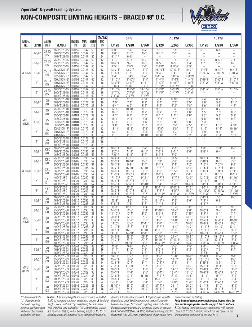
Notes: 1. Limiting heights are in accordance with AISI S100-12 using all steel non-composite design. 2. Limiting heights are established by considering flexure, shear, web crippling, and deflection. The web crippling values are based on testing with a bearing length of 1”. 3. For bending, studs are assumed to be adequately braced to
develop full allowable moment. 4. Viper25 and Viper20 distortional, local buckling moments and stiffness are based on testing. 5. For web crippling, when h/t≤ 200, the web crippling values are computed based on section C3.4.2 of AISI S100-07. 6. Web stiffeners are required for studs with h/t≥ 200, web crippling and shear values have
been confirmed by testing. Fully braced when unbraced length is less than Lu. See section properties table on pg. 5 for Lu values. 7. The factory punchouts are in accordance with section C5 of AISI S100-12. The distance from the center of the last punchout to the end of the stud is 12”.
“f”-flexure controls; “s”-shear controls; “w”-web crippling controls. No letter next to the number means deflection controls.
ViperStud® Drywall Framing System
NON-COMPOSITE LIMITING HEIGHTS – BRACED 48" O.C.
9
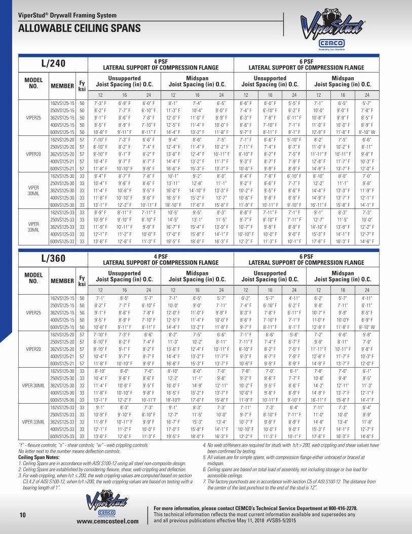
ViperStud® Drywall Framing System
ALLOWABLE CEILING SPANS
10
L/240 4 PSFLATERAL SUPPORT OF COMPRESSION FLANGE
6 PSFLATERAL SUPPORT OF COMPRESSION FLANGE
MODEL NO. MEMBER Fy
ksi
Unsupported Joist Spacing (in) O.C.
Midspan Joist Spacing (in) O.C.
Unsupported Joist Spacing (in) O.C.
Midspan Joist Spacing (in) O.C.
12 16 24 12 16 24 12 16 24 12 16 24
VIPER25
162VS125-15 50 7’-3” F 6’-9” F 6’-0” F 8’-1” 7’-4” 6’-5” 6’-6” F 6’-0” F 5’-5” F 7’-1” 6’-5” 5’-7”250VS125-15 50 8’-2” F 7’-7” F 6’-10” F 11’-3” F 10’-4” 9’-0” F 7’-4” F 6’-10” F 6’-2” F 10’-0” 9’-0” F 7’-8” F362VS125-15 50 9’-1” F 8’-6” F 7’-8” F 12’-0” F 11’-0” F 9’-9” F 8’-3” F 7’-8” F 6’-11” F 10’-8” F 9’-9” F 8’-5” F400VS125-15 50 9’-5” F 8’-9” F 7’-10” F 12’-5” F 11’-4” F 10’-0” F 8’-6” F 7’-10” F 7’-1” F 11’-0” F 10’-0” F 8’-9” F600VS125-15 50 10’-8” F 9’-11” F 8’-11” F 14’-4” F 13’-2” F 11’-8” F 9’-7” F 8’-11” F 8’-1” F 12’-9” F 11’-8” F 8’-10” W
VIPER20
162VS125-20 57 7’-10” F 7’-3” F 6’-6” F 9’-4” 8’-6” 7’-5” 7’-1” F 6’-6” F 5’-10” F 8’-2” 7’-5” 6’-6”250VS125-20 57 8’-10” F 8’-2” F 7’-4” F 12’-4” F 11’-4” F 10’-2” F 7’-11” F 7’-4” F 6’-7” F 11’-0” F 10’-2” F 8’-11”362VS125-20 57 9’-10” F 9’-1” F 8’-2” F 13’-6” F 12’-4” F 10’-11” F 8’-10” F 8’-2” F 7’-5” F 11’-11” F 10’-11” F 9’-8” F400VS125-21 57 10’-4” F 9’-7” F 8’-7” F 14’-4” F 13’-2” F 11’-7” F 9’-3” F 8’-7” F 7’-9” F 12’-8” F 11’-7” F 10’-3” F600VS125-21 57 11’-8” F 10’-10” F 9’-9” F 16’-6” F 15’-3” F 13’-7” F 10’-6” F 9’-9” F 8’-9” F 14’-9” F 13’-7” F 12’-0” F
VIPER 30MIL
162VS125-30 33 9’-4” F 8’-7” F 7’-8” F 10’-1” 9’-2” 8’-0” 8’-4” F 7’-8” F 6’-10” F 8’-10” 8’-0” 7’-0”250VS125-30 33 10’-4” F 9’-6” F 8’-6” F 13’-11” 12’-8” 11’-1” 9’-2” F 8’-6” F 7’-7” F 12’-2” 11’-1” 9’-8”362VS125-30 33 11’-4” F 10’-6” F 9’-5” F 16’-0” F 14’-10” F 13’-3” F 10’-2” F 9’-5” F 8’-6” F 14’-4” F 13’-3” F 11’-9” F400VS125-30 33 11’-8” F 10’-10” F 9’-8” F 16’-5” F 15’-2” F 13’-7” 10’-6” F 9’-8” F 8’-9” F 14’-9” F 13’-7” F 12’-1” F600VS125-30 33 13’-1” F 12’-2” F 10’-11” F 18’-10” F 17’-6” F 15’-8” F 11’-9” F 10’-11” F 9’-10” F 16’-11” F 15’-8” F 14’-1” F
VIPER 33MIL
162VS125-33 33 9’-9” F 8’-11” F 7’-11” F 10’-5” 9’-5” 8’-3” 8’-8” F 7’-11” F 7’-1” F 9’-1” 8’-3” 7’-3”250VS125-33 33 10’-9” F 9’-10” F 8’-10” F 14’-5” 13’-1” 11’-5” 9’-7” F 8’-10” F 7’-11” F 12’-7” 11’-5” 10’-0”362VS125-33 33 11’-9” F 10’-11” F 9’-9” F 16’-7” F 15’-4” F 13’-9” F 10’-7” F 9’-9” F 8’-9” F 14’-10” F 13’-9” F 12’-2” F400VS125-33 33 12’-1” F 11’-2” F 10’-0” F 17’-0” F 15’-8” F 14’-1” F 10’-10” F 10’-0” F 9’-0” F 15’-3” F 14’-1” F 12’-7” F600VS125-33 33 13’-6” F 12’-6” F 11’-3” F 19’-5” F 18’-0” F 16’-3” F 12’-2” F 11’-3” F 10’-1” F 17’-6” F 16’-3” F 14’-6” F
L/360 4 PSFLATERAL SUPPORT OF COMPRESSION FLANGE
6 PSFLATERAL SUPPORT OF COMPRESSION FLANGE
MODEL NO. MEMBER Fy
ksi
Unsupported Joist Spacing (in) O.C.
Midspan Joist Spacing (in) O.C.
Unsupported Joist Spacing (in) O.C.
Midspan Joist Spacing (in) O.C.
12 16 24 12 16 24 12 16 24 12 16 24
VIPER25
162VS125-15 50 7'-1" 6'-5" 5'-7" 7'-1" 6'-5" 5'-7" 6'-2" 5'-7" 4'-11" 6'-2" 5'-7" 4'-11"250VS125-15 50 8'-2" F 7'-7" F 6'-10" F 10'-0" 9'-0" 7'-11" 7'-4" F 6'-10" F 6'-2" F 8'-8" 7'-11" 6'-11"362VS125-15 50 9'-1" F 8'-6" F 7'-8" F 12'-0" F 11'-0" F 9'-9" F 8'-3" F 7'-8" F 6'-11" F 10'-7" F 9'-9" 8'-5" F400VS125-15 50 9'-5" F 8'-9" F 7'-10" F 12'-5" F 11'-4" F 10'-0" F 8'-6" F 7'-10" F 7'-1" F 11-0" F 10'-0"F 8'-9" F600VS125-15 50 10'-8" F 9'-11" F 8'-11" F 14'-4" F 13'-2" F 11'-8" F 9'-7" F 8'-11" F 8'-1" F 12'-9" F 11'-8" F 8'-10" W
VIPER20
162VS125-20 57 7'-10" F 7'-3" F 6'-6" 8'-2" 7'-5" 6'-6" 7'-1" F 6'-6" 5'-8" 7'-2" 6'-6" 5'-8"250VS125-20 57 8'-10" F 8'-2" F 7'-4" F 11'-3" 10'-2" 8'-11" 7'-11" F 7'-4" F 6'-7" F 9'-9" 8'-11" 7'-9"362VS125-20 57 9'-10" F 9'-1" F 8'-2" F 13'-6" F 12'-4" F 10'-11" F 8'-10" F 8'-2" F 7'-5" F 11'-11" F 10'-11" F 9'-8" F400VS125-21 57 10'-4" F 9'-7" F 8'-7" F 14'-4" F 13'-2" F 11'-7" F 9'-3" F 8'-7" F 7'-9" F 12'-8" F 11'-7" F 10'-3" F600VS125-21 57 11'-8" F 10'-10" F 9'-9" F 16'-6" F 15'-3" F 13'-7" F 10'-6" F 9'-9" F 8'-9" F 14'-9" F 13'-7" F 12'-0" F
VIPER 30MIL
162VS125-30 33 8'-10" 8'-0" 7'-0" 8'-10" 8'-0" 7'-0" 7'-8" 7'-0" 6'-1" 7'-8" 7'-0" 6'-1"250VS125-30 33 10'-4" F 9'-6" F 8'-6" F 12'-2" 11'-1" 9'-8" 9'-2" F 8'-6" F 7'-7" F 10'-8" 9'-8" 8'-5"362VS125-30 33 11'-4" F 10'-6" F 9'-5" F 16'-0" F 14'-9" 12'-11" 10'-2" F 9'-5" F 8'-6" F 14'-2" 12'-11" 11'-3"400VS125-30 33 11'-8" F 10'-10" F 9'-8" F 16'-5" F 15'-2" F 13'-7" F 10'-6" F 9'-8" F 8'-9" F 14'-9" F 13'-7" F 12'-1" F600VS125-30 33 13'-1" F 12'-2" F 10'-11"F 18'-10"F 17'-6" F 15'-8" F 11'-9" F 10'-11" F 9'-10" F 16'-11" F 15'-8" F 14'-1" F
VIPER 33MIL
162VS125-33 33 9'-1" 8'-3" 7'-3" 9'-1" 8'-3" 7'-3" 7'-11" 7'-3" 6'-4" 7'-11" 7'-3" 6'-4"250VS125-33 33 10'-9" F 9'-10" F 8'-10" F 12'-7" 11'-5" 10'-0" 9'-7" F 8'-10" F 7'-11" F 11'-0" 10'-0" 8'-9"362VS125-33 33 11'-9" F 10'-11" F 9'-9" F 16'-7" F 15'-3" 13'-4" 10'-7" F 9'-9" F 8'-9" F 14'-8" 13'-4" 11'-8"400VS125-33 33 12'-1" F 11'-2" F 10'-0" F 17'-0" F 15'-8" F 14'-1" F 10'-10" F 10'-0" F 9'-0" F 15'-3" F 14'-1" F 12'-7" F600VS125-33 33 13'-6" F 12'-6" F 11'-3" F 19'-5" F 18'-0" F 16'-3" F 12'-2" F 11'-3" F 10'-1" F 17'-6" F 16'-3" F 14'-6" F
“f” - flexure controls; “s” - shear controls; “w” - web crippling controls. No letter next to the number means deflection controls.Ceiling Span Notes:1. Ceiling Spans are in accordance with AISI S100-12 using all steel non-composite design. 2. Ceiling Spans are established by considering flexure, shear, web crippling and deflection.3. For web crippling, when h/t ≤ 200, the web crippling values are computed based on section
C3.4.2 of AISI S100-12, when h/t >200, the web crippling values are based on testing with a bearing length of 1”.
4. No web stiffeners are required for studs with h/t > 200, web crippling and shear values have been confirmed by testing.
5. All values are for simple spans, with compression flange either unbraced or braced at midspan.
6. Ceiling spans are based on total load of assembly, not including storage or live load for accessible ceilings.
7. The factory punchouts are in accordance with section C5 of AISI S100-12. The distance from the center of the last punchout to the end of the stud is 12”.
www.cemcosteel.com
For more information, please contact CEMCO’s Technical Service Department at 800-416-2278.This technical information reflects the most current information available and supersedes anyand all previous publications effective May 11, 2018 #VSB5-5/2015

ViperStud® Drywall Framing System
SCREW ALLOWABLE LOADS (lbs.)
11
MODEL NO.
DESIGN THICKNESS
(in)
MIN. THICKNESS
(in)
FYYIELD
(ksi)
FU TENSILE
(ksi)
#6 SCREW(0.138" dia; 0.25" head)
#8 SCREW(0.164” dia; 0.3125” head)
#10 SCREW(0.190” dia; 0.34” head)
C645 SCREW
PENETRATION TEST (P, F)SHEAR PULL OUT PULL OVER SHEAR PULL OUT PULL OVER SHEAR PULL OUT PULL OVER
VIPER25 0.0155 0.0147 50 50 759 30 97 909 36 121 939 42 132 PASS
VIPER20 (1-5/8" – 3-5/8") 0.0205 0.0195 57 57 1069 46 146 1249 54 183 1309 63 199 PASS
VIPER20 (4" – 6") 0.0220 0.0209 57 57 1299 49 157 1419 58 196 1449 98 213 PASS
VIPER 18mil 0.0188 0.0179 33 33 44 24 78 48 29 97 52 33 105 --
VIPER 30mil 0.0312 0.0296 33 33 95 40 129 103 48 161 111 55 175 --
VIPER 33mil 0.0346 0.0329 33 33 110 45 143 120 53 178 130 61 194 --
Notes:1. Capacities are based on section E4 of the AISI S100-12 Specification. 2. Capacities are based on Allowable Strength Design (ASD).3. Screw pull-out capacities are based on listed head diameter. 4. Two sheets of equal thickness and tensile strength are assumed in tabulated values.5. When materials of different steel thickness and tensile strength are connected, use the
lowest value for shear capacity (tilting and bearing), for pull-out capacity use sheet closest to screw tip and for pull-over capacity use sheet closest to screw head.
6. Where multiple fasteners are used, screws are assumed to have a center-to-center spacing of at least 3 times the nominal diameter.
7. Screws are assumed to have a center-of-screw to edge-of-steel dimension of at least 1.5 times the nominal diameter of the screw.
8. When screws are subjected to combination of shear and tension forces, interaction equation of AISI S100-12 Specification section E4.5 shall be used .
9. Viper25 & Viper20 shear values are tested per AISI S100-12 and AISI S905, tests conducted by Structural Testing & Research, Inc.
10. Non Structural Code Compliance Certification Program requires the Shear and Pullout values of a screw in Viper25 & Viper20 be equal or greater than the equivalent conventional stud.
Notes:• Rock-on is a registered trademark of ITW Buildex. • Durock is a registered trademark of the United States Gypsum Co. (USG)• Phillips is a registered trademark of the Phillips Screw Co. • Hi-Abuse, Hi-Impact, and Permabase are registered trademarks of the National Gypsum Co.
SCREW PENETRATION TESTING (ASTM C 645, ASTM C 1002)
To pass screw penetration tests, studs must be capable of pulling the head of the screw below surface of gypsum board in less than 2 seconds without spin out.
HI-ABUSE/HI-IMPACT – VIPER20
SHEATHING TYPE AND THICKNESS
STEEL FRAMING
SCREW TYPE
DRILL SPEED
(rpm)PASS/FAIL
ASTM-C-1002
USG 5/8” VHI 3-5/8” VIPER20
#6 X 1-1/4”TYPE S
SHARP PT
2500
4000
PASS
PASS
NATIONAL GYPSUM5/8” HIGH IMPACT
3-5/8” VIPER20
#6 X 1-1/4”TYPE S
SHARP PT
2500
4000
PASS
PASS
NATIONAL GYPSUM 5/8” HIGH ABUSE
3-5/8” VIPER20
#6 X 1-1/4”TYPE S
SHARP PT
2500
4000
PASS
PASS
CEMENT BOARD – VIPER20
SHEATHING TYPE AND THICKNESS
STEEL FRAMING SCREW TYPE
DRILL SPEED
(rpm)PASS/FAIL
ASTM-C-1002
USG 1/2” Durock® VIPER20
#9 BUILDEX ROCK-ON
2500
4000
PASS
PASS
#9 PHILLIPS CEMENT BOARD
2500
4000
PASS
PASS
NATIONAL GYPSUM 5/8” PERMABASE VIPER20
#9 BUILDEX ROCK-ON
2500
4000
PASS
PASS
#9 PHILLIPS CEMENT BOARD
2500
4000
PASS
PASS
GYPSUM BOARD – VIPER25 & VIPER20
1/2” TYPE C5/8” TYPE X5/8” TYPE X
VIPER25VIPER25VIPER20
#6 X1-1/4” TYPE S SHARP PTTYPE S SHARP PT
250025002500
PASSPASSPASS
www.cemcosteel.com
For more information, please contact CEMCO’s Technical Service Department at 800-416-2278.This technical information reflects the most current information available and supersedes anyand all previous publications effective May 11, 2018 #VSB5-5/2015

ViperStud® Drywall Framing System
ACOUSTIC PERFORMANCE (ASTM E 90)
12www.cemcosteel.com
For more information, please contact CEMCO’s Technical Service Department at 800-416-2278.This technical information reflects the most current information available and supersedes anyand all previous publications effective May 11, 2018 #VSB5-5/2015
41
46
61
• R-13 fiberglass insulation • RC-Max resilient channel, one side• 1 Layer 5/8” type X GWB, each side
44
VIPER25 16” O.C.
STC Rating
• R-13 fiberglass insulation • 1 Layer 5/8” type X GWB, each side
51
47
52
VIPER25 24” O.C.
STC Rating
VIPER20 16” O.C.
STC Rating
49• R-13 fiberglass insulation • 1 Layer 5/8” type X GWB, one side• 2 Layers of type type X GWB, other side
• R-13 fiberglass insulation •1 Layer 5/8” type X GWB, each side
WALL TYPES
A
B
C
D
E
• R-11 fiberglass insulation• RC channel 1 side• Double layers of 5/8” type X GWB, each side
• 1 Layer of 5/8” type X GWB, each side
• R-11 fiberglass insulation • 1 Layer of 5/8” type X GWB, each side
• R-11 fiberglass insulation• RC1 channel 1 side, • 1 Layer of 5/8” type X GWB, each side
The ViperStud® drywall framing system has been tested to determine the transmission of sound through walls. Acoustic tests were performed using 3-5/8” ViperStud steel studs. The tests were performed according to ASTM E 90 in different configurations. May use RC-1 or RC1-X.
Sound testing performed by Western Electro-Acoustic Laboratory and Architectural Testing, Inc.

ViperStud® Drywall Framing System
FIRE TESTING DATA (ASTM E 119)
13www.cemcosteel.com
For more information, please contact CEMCO’s Technical Service Department at 800-416-2278.This technical information reflects the most current information available and supersedes anyand all previous publications effective May 11, 2018 #VSB5-5/2015
VIPERSTUD® ISFIRE TESTED
1 Hour Wall Assembly
2 Hour Wall Assembly
3 Hour Wall Assembly
4 Hour Wall Assembly
Insulation shown is optional in most assemblies.Check UL Design Guide for rated assembly requirements.
UL Design No. ViperStud Min. Thickness Wall Rating: UL Design No. ViperStud Min. Thickness Wall Rating:U375 Viper25 2 HR V412 Viper20 2 HRU403 Viper20 2 HR V416 Viper20 1 HRU407 Viper25 1/2 or 1 HR V417 Viper25 1 HRU408 Viper20 2 HR V418 Viper20 2 HRU411 Viper20 2 HR V419 Viper20 2 HRU412 Viper20 2 HR V425 Viper20 1 HRU419 Viper25 1, 2, 3 or 4 HR V435 Viper25 1 HRU421 Viper20 2 HR V437 Viper20 1 HR ChaseU431 Viper20 4 HR V438 Viper25 1, 2, 3, or 4 HRU435 Viper20 3 or 4 HR V443 Viper20 4 HRU436 Viper20 1, 2, or 3 HR V444 Viper20 1 HRU450 Viper20 1, 3, or 4 HR V448 Viper25 1 HRU451 Viper20 1 HR V449 Viper20 2 HRU454 Viper20 2 HR V452 Viper25 1 or 2 HRU463 Viper20 3 or 4 HR V469 Viper25 1 or 2 HR ChaseU465 Viper20 1 HR Chase V476 Viper20 1, 3, or 4 HRU466 Viper20 1 HR V486 Viper25 1, 2, or 2-1/2 HRU471 Viper20 1-1/2 HR V488 Viper25 1 or 2 HR ChaseU475 Viper20 1, 2, 3 or 4 HR V489 Viper25 1, 2, 3, or 4 HRU478 Viper20 3 HR V496 Viper20 1 or 2 HR ChaseU491 Viper20 2 HR V498 Viper25 1, 2, 3, or 4 HRU493 Viper25 1, 2 HR Chase W411 Viper25 1/2 or 1 HRU494 Viper20 1 HR W415 Viper20 1 or 2 HRU495 Viper20 1 or 2 HR W423 Viper25 1/2 or 1 HRU496 Viper20 1 HR W424 Viper25 1/2 or 1 HRV410 Viper20 2 HR W432 Viper25 2 HR
W433 Viper25 1/2 HRNote: Check UL Design assembly for minimum stud web width and other requirements.Visit www.cemcosteel.com for more information on fire rated assemblies.
VIPERSTUD® FIRE TESTING DATA (ASTM E119)

IMPACT TESTING (ASTM C 1629)ViperStud® Drywall Framing System
14www.cemcosteel.com
For more information, please contact CEMCO’s Technical Service Department at 800-416-2278.This technical information reflects the most current information available and supersedes anyand all previous publications effective May 11, 2018 #VSB5-5/2015
Test Summary:All tests were conducted to ASTM C 1629 standard using Test Method ASTM E 695 for Soft Body Impact Tests and ASTM C 1629 Annex 1 forHard Body Impact Tests. Each test was repeated 3 times as required by the test method and results reported to the ASTM standard publishedvalues for Level Classification.
Test Materials:Steel Studs – Viper20 Stud and track spaced 16” o.c., do not use ViperTrack25 on Viper20 studs for impact resistant walls. Tests conducted using USG® & National Gypsum® boards.
Testing conducted by IAS Certified 3rd party testing lab Intertek Testing Services.
NATIONAL GYPSUM®
Soft Body Impact Test Board Assembly ClassificationSingle Drop 3-5/8” NGC Hi-Abuse Level 2
Soft Body Impact Test Board Assembly ClassificationSingle Drop 3-5/8” NGC Hi-Impact Level 3
Soft Body Impact Test Board Assembly ClassificationProgressive Drop 3-5/8” NGC Hi-Abuse Level 1
Soft Body Impact Test Board Assembly ClassificationProgressive Drop 3-5/8” NGC Hi-Impact Level 3
Hard Body Impact Test Board Assembly ClassificationSingle Drop 3-5/8” NGC Hi-Impact Level 3
USG®
Soft Body Impact Test Board Assembly ClassificationSingle Drop 3-5/8” USG FiberRock AR Level 2
Soft Body Impact Test Board Assembly ClassificationProgressive Drop 3-5/8” USG FiberRock VHI Level 3
Hard Body Impact Test Board Assembly ClassificationSingle Drop 3-5/8” USG FiberRock AR Level 1
Hard Body Impact Test Board Assembly ClassificationSingle Drop 3-5/8” USG FiberRock VHI Level 3
Generic 5/8” Type X Board
NGC 5/8” Hi-ImpactHi-Abuse
3-5/8” Viper20
Generic 5/8” Type X Board
USG 5/8” FiberRock ARFiberRock VHI
3-5/8” Viper20
Soft body impact test using ViperStud.
- FiberRock VHI & FiberRock AR are registered trademarks of the United States Gypsum Co. (USG)- Hi-Abuse, Hi-Impact, & Permabase are registered trademarks of the National Gypsum Co.- ProRoc & ProRoc Extra are registered trademarks of Certainteed.- Protecta AR 100 is a registered trademark of Lafarge Gypsum.- ComfortGuard AR & ComfortGuard IR are registered trademarks of Temple-Inland.- Dens Brand is a trademark of Georgia Pacific.

CEMCO STRUCTURAL ENGINEERING
The CEMCO Structural Engineering division provides solutions that make sure your buildings are designed to current codes and specifications. Our methodology helps you control costs and keep your projects on schedule. We work closely with owners, designers, and contractors to facilitate efficient project execution.
The structural engineering division uses state-of-the-art software and technologies to streamline the request, design, and issuance processes to cut costs and save time on your projects.
Let the experienced CEMCO Structural Engineering team add value to your project with the following services:
• Thorough review of your architectural plans to determine structural requirements.
• Member sizing and cost estimation for preliminary and conceptual designs.• Professional, certified engineering shop drawing and calculations.• Use our project submittal form to submit your project online.
CEMCO STRUCTURAL ENGINEERING 1-2-3 PROCESS
1 Review client structural and architectural plans.
2 Deliver shop drawings and structural solutions based on the client’s needs.
3 Provide full engineering support through the life of the project.
CEMCO warrants to Purchaser only the Products to be free from defects in material and workmanship for a period of one year from the date of delivery, subject to CEMCO’s standard manufacturing and commercial variations and practice. CEMCO MAKES NO OTHER REPRESENTATIONS OR WARRANTIES TO PURCHASER REGARDING THE PRODUCTS AND EXPRESSLY DISCLAIMS ALL OTHER IMPLIED OR EXPRESS WARRANTIES, INCLUDING ALL WARRANTIES OF MERCHANTABILITY AND FITNESS FOR A PARTICULAR PURPOSE. CEMCO’s Product Warranty does not apply to any Product to the extent it has been subject to (1) other than normal wear and tear, or (2) improper installation, alteration, modification, or repair, tampering, negligence, abuse or accident, or (3) improper storage. LIABILITY IS LIMITED TO REPAIR OR REPLACEMENT, AT CEMCO’S OPTION, OF ANY DEFECTIVE PRODUCT. CEMCO will repair and replace, at its option, Products which upon inspection it finds to be defective, based on claims made in writing to CEMCO within a reasonable time after discovery. Products alleged to be defective must be returned, freight prepaid, within thirty (30) days to CEMCO with the return authorization number, obtained from CEMCO, clearly
marked on the outside of the return container for repair or replacement by CEMCO. THE ABOVE WARRANTY SHALL CONSTITUTE PURCHASER’S EXCLUSIVE REMEDY WITH RESPECT TO THE PRODUCTS FURNISHED HEREUNDER. IN NO EVENT SHALL CEMCO BE LIABLE OR RESPONSIBLE TO PURCHASER OR ANY OTHER PERSON FOR ANY SPECIAL, INDIRECT OR CONSEQUENTIAL LOSSES OR DAMAGES, WHETHER BASED ON CONTRACT, TORT, STRICT LIABILITY OR OTHER THEORY OF LAW, EVEN IF CEMCO SHALL HAVE BEEN ADVISED OF THE POSSIBILITY OF ANY LOSS OR DAMAGES, ALL SUCH DAMAGES AND CLAIMS BEING SPECIFICALLY DISCLAIMED. IN NO EVENT SHALL CEMCO’S LIABILITY EXCEED THE PURCHASE PRICE OF THE PRODUCT.
All transactions shall be governed by the laws of the State of California (including, without limitation, the provisions of the California Commercial Code), without giving affect to any conflict of law rule or principle of such state. The United Nations Convention for the International Sale of Goods shall not apply to this agreement.
15

ViperStud® Drywall Framing System
SFIA – CODE COMPLIANCE CERTIFICATION PROGRAM
16www.cemcosteel.com
For more information, please contact CEMCO’s Technical Service Department at 800-416-2278.This technical information reflects the most current information available and supersedes anyand all previous publications effective May 11, 2018 #VSB5-5/2015
CODE COMPLIANCE CERTIFICATION PROGRAM
SFIA developed, an industry supported Code Compliance Certification Program endorsed by the Association of the Wall and Ceiling Industry. The program is accessible to all manufacturers to certify that structural and nonstructural cold-formed steel framing they produce complies with the IBC 2015 code requirements.
Structural and nonstructural cold-formed steel framing certification is administered and audited by an independent third Administrator meeting IAS AC98 requirements and demonstrating compliance with ISO/IEC Standard 17020.
The validation process includes a minimum of two unannounced manufacturing audits per year of each facility operated by a manufacturer, as well as on-going random selection and independent testing of certified structural and nonstructural cold-formed steel framing products.
Manufacturing facilities that satisfy the requirements for certification are authorized to label structural and nonstructural cold-formed steel framing members they produce as “certified code compliant.” Check the updated list of Certified Production Facilities at Intertek's website at http://www.intertek.com/building/sfia/.
IAS#AA-676
Independen t I n spec t ion by :IBC AND IRCASTM C645ASTM A1003/A1003M
ASTM B117AISI S220
ART / COPY PROOF
CUSTOMER
COPY DIRECTION
J & N PART #
SFIA
LABEL SIZE MATERIAL
DESCRIPTION
SFIA Non Structural
3X16NS
3.00 x 16.00 Durable PolyPro
UV / LAMINATE OPTION
CYAN MAGENTA YELLOW BLACK PMS PMS PMS PMS
CYAN MAGENTA YELLOW BLACK PMS 7490
DATE 01-03-2018
NOTICE: This artwork and barcode may have been modified by J&N Associatesto ensure both printability and scannability.Please double check all fold lines, perf lines, score lines, varnish/opaque areas, etc prior to approving.
5
PLEASE READ AND ACKNOWLEDGE
PROOF APPROVAL NOTES
Please contact your CSR to inform themof proof approval or changes needed.PROOF CREATED BYJ & N Job Number
PGL-010320181697
INK COLORS - FRONT
INK COLORS - BACK
2
1 3
4
5
6
UVPATTERN UV VARNISH MATTE LAMINATE
PLEASE PROOF CAREFULLY FOR ACCURACY
PLEASE PROOF READ! This proof is an actual copy of the artwork from which your job will be printed. It is submitted for your review and approval. Please examine for any errors in placement, spelling, size, fonts, color, material, part number, unwind, UV / Laminate options or design. If any errors are found, mark them clearly on the proof or compile a clear list of them in an email and return it to your customer service representative. We cannot be responsible for any errors in this copy after the return of this proof with your approval.Please note that extensive changes or delay in returning this proof willdelay the final delivery date of your order.In submitting this proof, we assume no responsibility for non-compliance with local, state or federal laws and regulations. If this print is to be used in connection with products subject to any governmental labeling regulations, it is your responsibility to determine whether this copy complies with these regulations, as we cannot render legal opinions.
PROOF: 2 X PROOF APPROVED DATE ______________
Approved By:__________________________
PROOF NOT APPROVED Changes/Revisions 8
7
NONE
NOTE: This proof does NOT show accurate color! Do not use color printout for color match. Refer to PMS numbers for color reference or provide a sample for color matching with your order.
J & N Associates404-402-3186

ViperStud® Drywall Framing System
NOTES
17www.cemcosteel.com
For more information, please contact CEMCO’s Technical Service Department at 800-416-2278.This technical information reflects the most current information available and supersedes anyand all previous publications effective May 11, 2018 #VSB5-5/2015

ViperStud® Drywall Framing System
NOTES
18www.cemcosteel.com
For more information, please contact CEMCO’s Technical Service Department at 800-416-2278.This technical information reflects the most current information available and supersedes anyand all previous publications effective May 11, 2018 #VSB5-5/2015

ViperStud® Drywall Framing System
NOTES
19www.cemcosteel.com
For more information, please contact CEMCO’s Technical Service Department at 800-416-2278.This technical information reflects the most current information available and supersedes anyand all previous publications effective May 11, 2018 #VSB5-5/2015

Expanding Your Solutions
Effective 5/11/2018 | #VSB5-5/2015
Pittsburg, CA
City of Industry, CA
Denver, CO
Ft. Worth, TX
Corporate Headquarters13191 Crossroads Parkway North, Suite 325, City of Industry, CA 91746
P: 800.775.2362 | F: 626.330.7598
Southern California Manufacturing Facility263 North Covina Lane, City of Industry, CA 91746
P: 800.775.2362 | F: 626.330.7598
Northern California Manufacturing Facility1001-A Pittsburg Antioch Hwy, Pittsburg, CA 94565
P: 925.473.9340 | F: 925.473.9341
Denver Colorado Manufacturing Facility490 Osage Street, Denver, CO 80204
P: 303.572.3626 | F: 303.572.3627
Fort Worth Texas Manufacturing Facility8600 Will Rogers Blvd, Fort Worth, TX 76140
P: 817.568.1525 | F: 817.568.2759
www.cemcosteel.com