virtual blind stick - engineeringjunjie/project/sp6.pdf · multimeter - i . executive summary ....
TRANSCRIPT
Virtual Blind Stick
Project Duration:
May 23, 2013 — August 7, 2013
Project Submission Date:
August 7, 2013
Prepared by: Fei Ye
Ma Yixin Shen Junjie Wu Mingqiu
Yang Zhaohong Undergraduate Engineers UM-SJTU Joint Institute
Team Multimeter
Prepared for: Dr. Roberto Dugnani
Associate Research Scientist, VG100 Professor UM-SJTU Joint Institute
Dr. Rockwell Clancy Technical Communications Lecturer, VG100 Instructor
UM-SJTU Joint Institute
Multimeter - i
Executive Summary This report introduces our design of a virtual blind stick. The goal of it is to find a new way to help blind people walking. The blind in China are a large group of people. However, the unsound facilities for the blind cannot ensure them the safety of going out. Common blind stick is not the best method to solve this problem because it’s inconvenient to carry, inefficient to use and lessens the user’s dignity in some way. So, blind people really need a portable, efficient and covert guide. Also, our product is expected to be cheaper than congeneric products in the market, which lets most blind people be able to afford one intelligent crutch. We set three main parts in our criteria, which are the user-friendless, sustainability and durability and functionality. We include all the main goals we expect our design to achieve in it. All the expectations in criteria are set according to requirement of blind people and our technique level. We have considered many aspects in our criteria, including shape, weight, practicability, functionality and user’s feeling. Our design will be made on the basis of criteria strictly. Thus, our team designed the Virtual Blind Stick for helping the blind people walk without the traditional blind stick, which is long, heavy and inconvenient. When the user places the device in the right position on their body, the sensor will detect the road situation ahead of him/her, both on the ground and in the air. Whenever the sensor detects the changes of road situation which may cause danger to the user, he/she will be warned in time. In this sense, the Virtual Blind Stick can successfully substitute the traditional one. Furthermore, it is smaller but has more functions at the same time. Later we have a test on our prototype. There are three parts in our prototype tests: measure the accuracy of the on-waist device to detect the obstacles ahead, the accuracy of the on-waist device to detect the pit ahead, and the accuracy of the on-hand device to detect the obstacle around the user. The result is quite satisfying. To summarize, our design reaches most goals we have set. In addition, our device protects the blinds dignity. They no longer have to bring the blind stick which clearly shows that they are blind. Besides, although our design is not so efficient, it introduces a new concept of using modern technics to help blind people. After further developing, it is possible to put design into industry. To gain a better design, first we suggest choosing a more friendly and efficient way to alarm. Second, a stable structure is needed. Besides, special obstacles such as doorsills and door curtains need to be distinguished, and hence more accurate sensors are recommended. Furthermore, functions such as telling the direction and location can be added.
Multimeter - ii
Table of Contents 1. INTRODUCTION ...................................................................................................................... 1
2. BACKGROUND ........................................................................................................................ 1
2.1 Chinese Conditions Concerning the Blind People ............................................................ 1
2.2 Problems with Common Blind Stick ................................................................................. 2
2.3 Existing Designs ................................................................................................................ 2
2.3.1 Electronic talking stick for the blind ....................................................................... 2
2.3.2 White stick for blind persons ................................................................................... 2
2.3.3 System for guiding the visually handicapped .......................................................... 2
3. CRITERIA .................................................................................................................................. 3
3.1 User-Friendliness ............................................................................................................... 3
3.2 Durability and Sustainability ............................................................................................. 3
3.3 Functionality ...................................................................................................................... 3
4. FINAL DESIGN ......................................................................................................................... 4
4.1 Design Overview ............................................................................................................... 4
4.2 On-Waist Part .................................................................................................................... 5
4.3 On-Hand Part ..................................................................................................................... 9
5. PROTOTYPE ........................................................................................................................... 11
6. EVALUATIONS ...................................................................................................................... 12
6.1 On-Waist Part .................................................................................................................. 12
6.1.1 Measure the accuracy of detecting obstacle ahead .............................................. 12
6.1.2 Measure the accuracy of detecting a pit ahead ..................................................... 12
6.2 On-Hand Part ................................................................................................................... 13
6.2.1 Measure the accuracy of detecting obstacles around ........................................... 13

Multimeter - iii
7. RECOMMENDATIONS .......................................................................................................... 14
7.1 To Users ........................................................................................................................... 14
7.2 To Designers .................................................................................................................... 14
8. CONCLUSION ......................................................................................................................... 15
REFERENCES ............................................................................................................................. 16
Appendix A: Gantt Chart .......................................................................................................... A – 1
Appendix B: Code..................................................................................................................... B – 1
Appendix C: CAD Drawing...................................................................................................... C – 1
Appendix D: Test Data ............................................................................................................. D – 1
Appendix E: WHO Report ........................................................................................................ E – 1
Appendix F: Electronic Talking Stick for the Blind .................................................................. F – 1
Appendix G: White Stick for Blind Persons ............................................................................. G – 1
Appendix H: System for Guiding the Visually Handicapped ......................................................... H – 1
Appendix I: Cost Analysis ..........................................................................................................I – 1
List of Figures Figure 2.1 Blind Track .................................................................................................................. 1
Figure 2.2 Common Blind Stick ................................................................................................... 2
Figure 4.1 Usage of Virtual Blind Stick ....................................................................................... 4
Figure 4.2 Design Overview ......................................................................................................... 5
Figure 4.3 On-Waist Part .............................................................................................................. 6
Figure 4.4 Arduino Mega 2560 Front and Back ........................................................................... 7
Figure 4.5 MP3 Shield .................................................................................................................. 7
Figure 4.6 Ultrasonic Sensor ......................................................................................................... 8
Figure 4.7 How the Ultrasonic Sensor Works .............................................................................. 8

Multimeter - iv
Figure 4.8 3D View of the Frame of the On-Waist Part in CAD ..................................................9
Figure 4.9 On-Hand Part ................................................................................................................9
Figure 4.10 Arduino Pro Mini Front and Back .............................................................................. 10
Figure 4.11 The Inside Structure of the Oscillator ........................................................................ 10
Figure 4.12 3D View of the Frame of the On-Hand Part in CAD ................................................. 11
Figure 5.1 First Prototype ............................................................................................................ 11
Figure 5.2 Final Prototype ........................................................................................................... 11
Figure 6.1 Error Rate of Detecting Obstacles Ahead .................................................................. 12
Figure 6.2 Error Rate of Detecting a Pit Ahead ........................................................................... 13
Figure 6.3 Error Rate of Detecting Obstacles Around ................................................................. 13

Multimeter - 1
1. INTRODUCTION The goal of our project is to find a new way to help blind people walking. There is a large group of blind people in China. However, due to the ridiculous blind tracks, they have difficulty going out. Common blind stick is not the best method to solve this problem because it’s inconvenient to carry, inefficient to use and lessens the user’s dignity in some way. So, blind people really need a portable, efficient and covert guide. Also, our product is expected to be cheaper than congeneric products in the market, which lets most blind people be able to afford one intelligent crutch. Our solution to the walking problem of blind people is to detect the conditions of the ground around and then provide immediate feedbacks to the users. Ultrasonic sensors are applied to measure the height of the ground and the distance between the user and possible obstacles. Our design is divided into two parts. One is the on-hand part, which is fixed on the user’s hand and is used to find obstacles in all directions; the other is the on-waist part, which is attached on the use’s waist and focuses on the conditions of the ground. The feedbacks will be conveyed to the users though an oscillator and an earphone.
This report is intended to provide details of our project for people who are interested in it or want to improve it. The following parts cover the necessary background, the criteria we set for our project, the final design and the current prototype, the test we conducted, the recommendations for the users and other designers, the conclusion we drew and the references.
2. BACKGROUND This section provides necessary information for our project, including the Chinese conditions concerning the blind, the problems with the common blind stick and existing designs.
2.1 Chinese Conditions Concerning the Blind People According to the report of WHO (2010) about Chinese blindness problem (See Appendix E), there were about 5 million blind people in China at that time, which is the biggest number among all the countries, and “By definition, these people cannot walk about unaided.” This number keeps increasing these years. Hence, the blind in China are a large group of people. However, facilities for them are far from good, especially the blind tracks. Horrible blind tracks are often seen even in the biggest cities like Beijing and shanghai (Figure 2.1). The safety of this group of people is obviously not secured.
Figure 2.1: Blind Track (Figure 2.1 is from
http://qiyuan.youth.cn/perspective/201211/t20121115_2617314_5.html)

Multimeter - 2
2.2 Problems with Common Blind Stick There are mainly three problems with the common blind stick (Figure 2.2). First, it’s inconvenient to carry because one of the user’s hands will be occupied with a long stick all the time. Next, it’s inefficient to use. In the street, blind people with a common blind stick have to walk at a very slow pace. Also, a long stick in hand clearly shows the disability of the user which actually lessens user’s dignity. So, blind people really need a portable, efficient and covert guide.
2.3 Existing Designs Now, in the market, there are several intelligent blind crutches similar to our project. Here are three examples. However, compared to the common blind stick, their utilization is much less. The main reason is the high price.
2.3.1 Electronic talking stick for the blind
This stick can talk to guide a blind person to walk and go upstairs and downstairs, and to warn the user of dangerous pits in road, and can even call for help when the user falls (See Appendix F). This design is much humanized. However, it fails to meet the criterion of portability.
2.3.2 White stick for blind persons
A transmitter and a receiver are fixed on a white stick to emit directed signals and receive reflected ones (See Appendix G). The display means based on a rotatable and a ring-shaped element transfers received signals into perceptible instructions for the user. This design has similar testing concept to our project. However, it fails to meet the criterion of portability, too.
2.3.3 System for guiding the visually handicapped
The system includes a wire or strip with a uniform conductivity embedded within a blind track, the detector in a shoe of the blind or a tip of a blind stick, and a vibrator, in electrical communication with the detector (See Appendix H). Through vibration, the blind person is able to know his proximity to the electrical conductor to determine that he is proceeding in a proper direction within or along the blind track. This system seems very efficient and safe. However, in China, now, it’s impossible to build so many intelligent blind tracks which are a necessity in this system.
Figure 2.2: Common Blind Stick (Figure 2.2 is from
http://ltpic.cn/download_page. php?id=238318&catid=0)

Multimeter - 3
3. CRITERIA This section introduces the criteria for our visual blind stick. We set several points of criterion by ourselves. We act as blind people at the beginning of our project 2 to know the requirement of them. All the criteria were set based on the requirement of blind people and our expectation of the product. These criteria could help us make our product more targeted.
3.1 User-Friendliness At first, the reason why we wanted to create such a product was that we wanted to provide the blind people an easier way to walk in their daily life. Therefore, the requirement and feeling must be one of the most important points for us to think about. Thus, we supposed that our design should be easy to carry, to use and to adjust for a blind person. We needed our design to be at least 50% lighter and more portable than the traditional blind stick, so that a blind person can save more physical power. Compared with the traditional blind stick which must be held and swung all the time while walking, our design should be easier to use in two aspects, which were the weight and size. For product which is designed for blind people, we should also make the way to use as simple as possible. Because we could not ask a blind person to pay much time to learn how to use a complex device, which was unacceptable. Thus, we expected that a blind person only needed to turn on or off something like a switch to make the device work or stop, without any other adjustment during the using time.
3.2 Durability and Sustainability Except some one-time-used products, sustainability will certainly be an essential factor to judge whether a product is qualified or not. In addition, for a product must be used with energy, durability has the similar status with sustainability. Since we considered that our design was a daily appliance for the blind which may be used very frequently, it should be good enough in sustainability. Limited by the material and technology we could use, we could only set a duration which was about one year long as our goal in sustainability of our design; and the truth was that we could not test the real sustainable time, thus the sustainability was definitely a serious problem and challenge for us. The durability was also a key point for our design. We must make the product powerful enough so that is will not be out of power while a blind person is using it in some public places. However, we could only set the effective time for each battery as about 10 hours. We may try to make some improvement in these two aspects.
3.3 Functionality In our design, the most essential thing for our product is that it can do what the traditional stick do, namely, to detect obstacles and warn the blind person. This is the basis on which we can substitute the traditional blind stick by our new design. Whatever other functions our design has, these two are always the most important. We expect that our design can find any obstacle ahead of the blind person within about one meter. More importantly, our design should also be able to detect stairs and holes on the ground. What we need to improve is the sensitivity of our design.

Multimeter - 4
4. FINAL DESIGN 4.1 Design Overview Our team designed the Virtual Blind Stick for helping the blind people walk without the traditional blind stick, which is long, heavy and inconvenient. When the user places the device in the right position on their body (Figure 4.1), the sensor will detect the road situation ahead of him/her, both on the ground and in the air. Whenever the sensor detects the changes of road situation which may cause danger to the user, he/she will be warned in time. In this sense, the Virtual Blind Stick can successfully substitute the traditional one. Furthermore, it is smaller but has more functions at the same time.
Figure 4.1: Usage of Virtual Blind Stick

Multimeter - 5
Our design, the Virtual Blind Stick, can be divided into two parts. The big one is called the on-waist part while the small one is called the on-hand part. The names come from the position where they are placed on the user’s body. Figure 4.2 gives an overview of our design. The materials we applied and the costs are listed in Appendix I. The code we programmed can be seen in Appendix B.
Figure 4.2: Design Overview
4.2 On-Waist Part The on-waist part (Figure 4.3) is designed to be pinned on the belt because the waist is one of the most stable parts of a human body when walking while the other parts will shake a lot. Its main job is to detect the ground changes, such as walls as well as stairs both upwards and downwards. Thus it plays a dominant role in our design. In addition, it uses earphones to clearly warn the user out of danger from the sudden ground changes. The on-waist part includes four main components – an Arduino Mega 2560 board, an MP3 shield, an ultrasonic sensor and the frame.

Multimeter - 6
Figure 4.3: On-Waist Part
Arduino Mega 2560 “Arduino is an open-source electronics prototyping platform based on flexible, easy-to-use hardware and software. It's intended for artists, designers, hobbyists and anyone interested in creating interactive objects or environments.” (Retrieved from www.arduino.cc, 2013) We used Arduino to sense the road situation by receiving input from the ultrasonic sensor and then react to the sudden situation changes by warning the user. The reason why we used the Arduino Mega 2560 with a large size is because no other Arduino boards have the same amount of receive (RX) and transmit (TX) TTL serial pins which can satisfy our demands. Figure 4.4 shows both the front and back of the Arduino Mega 2560 board.
Ultrasonic Sensor
MP3 Shield
Arduino Mega 2560
Frame
Multimeter - 7
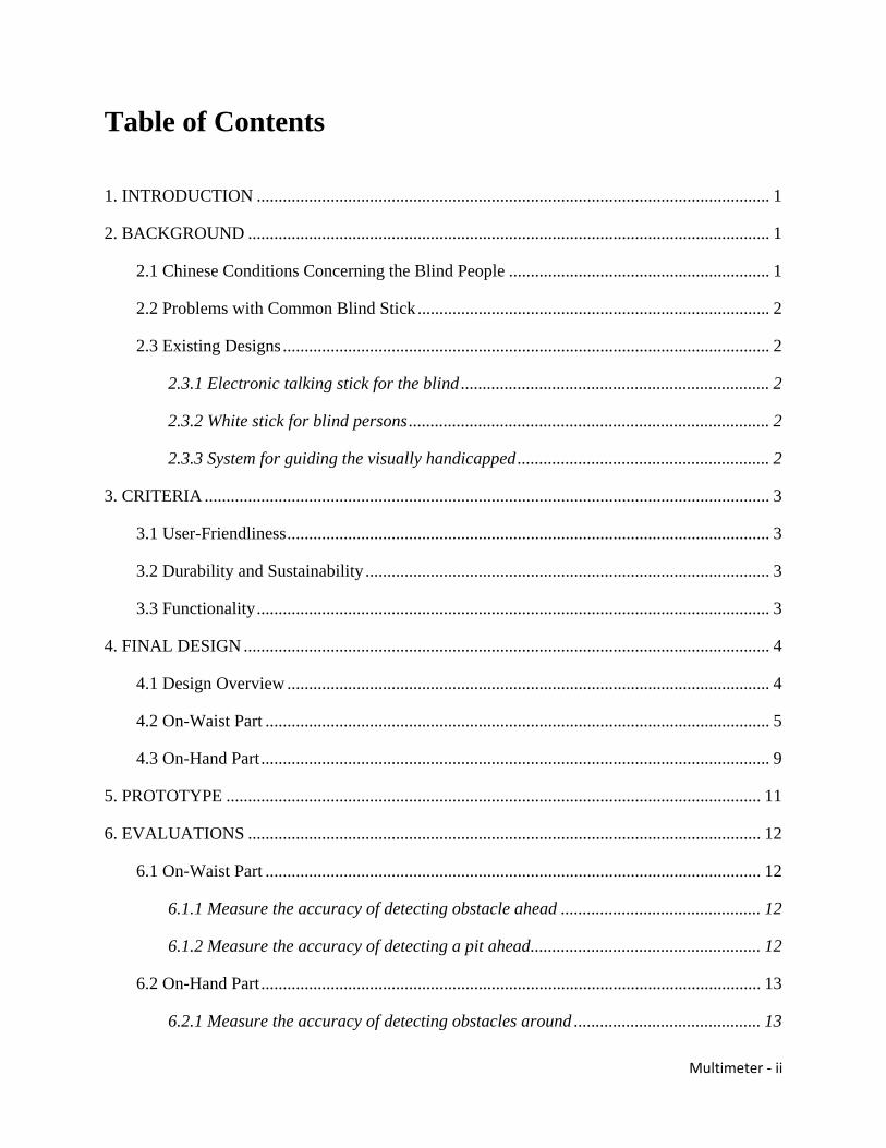
Figure 4.4: Arduino Mega 2560 Front and Back (Figure 4.4 is from http://arduino.cc/en/Main/arduinoBoardMega2560)
MP3 shield Arduino has a lot of extension modules to expand its functions and MP3 shield is one of them. It can play music both from SD card and U-disk. We used it to give oral warnings to the user directly when there is a sudden ground change. The sound “High” from the earphones indicates the higher ground in front of the user while the sound “Low” indicates the lower ground. Figure 4.5 shows the appearance of the MP3 shield.
Figure 4.5: MP3 Shield
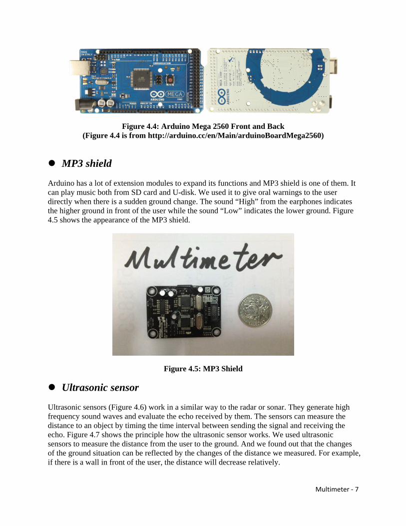
Ultrasonic sensor Ultrasonic sensors (Figure 4.6) work in a similar way to the radar or sonar. They generate high frequency sound waves and evaluate the echo received by them. The sensors can measure the distance to an object by timing the time interval between sending the signal and receiving the echo. Figure 4.7 shows the principle how the ultrasonic sensor works. We used ultrasonic sensors to measure the distance from the user to the ground. And we found out that the changes of the ground situation can be reflected by the changes of the distance we measured. For example, if there is a wall in front of the user, the distance will decrease relatively.

Multimeter - 8
Figure 4.6: Ultrasonic Sensor
Figure 4.7: How the Ultrasonic Sensor Works (Figure 4.7 is from http://www.robotc.net/wiki/Tutorials/Arduino_ Projects/Mobile_Robotics/BoeBot/What_Is_An_Ultrasonic_Sensor)
Frame Almost every electronic product has a frame, not only to protect the electronic components inside but also to make it more humanized, not excepting our design, the Virtual Blind Stick. For the material, we decided to choose plexiglass, also known as PMMA, because of its moderate properties, easy handling and processing, and low cost. Most important of all, it is very light and solid. For the structure, we tried to make it as small as possible. Besides, it should be also good-looking. Figure 4.8 shows the 3D view of the frame of the on-waist part in CAD. See more details in Appendix C.

Multimeter - 9
Figure 4.8: 3D View of the Frame of the On-Waist Part in CAD
4.3 On-Hand Part The on-hand part (Figure 4.9) is designed to be fastened on the back of the user’s hand so that it will be more flexible to use. Comparing to the on-waist part, the on-hand part plays a helping role. Instead of detecting the ground changes, it is used to check whether there are obstacles above the waist. Whenever the on-hand part successfully detects the obstacles, the oscillator will shake to give the user a warning. The on-hand part includes four main components – an Arduino Pro mini board, an ultrasonic sensor, an oscillator and the frame.
Figure 4.9: On-Hand Part
Ultrasonic Sensor
Oscillator
Arduino Pro Mini
Frame

Multimeter - 10
Arduino Pro Mini Arduino Pro Mini is one of the smallest Arduino boards at present which is available to ordinary customers. It has almost all the functions we need for the on-hand part. We used Arduino Pro Mini to sense the obstacles around the user by receiving input from the ultrasonic sensor and then react to the sudden situation changes by vibrating the oscillator to warn the user. Figure 4.10 shows the both the front and back of the Arduino Pro Mini board.
Figure 4.10: Arduino Pro Mini Front and Back (Figure 4.10 is from http://arduino.cc/en/Main/ArduinoBoardProMini)
Ultrasonic sensor This part has been mentioned before. See 4.2-Ultrasonic sensor.
Oscillator Oscillator is widely used in cell phones for vibrating. It is made up of a micro motor and a balance weight which is set on the motor. When the current is switched on, the balance weight will make vibration since the center of the mass of the balance weight is not on the spin axis. We used the oscillator for the on-hand part to warn the user out of danger from the obstacles around him/her above the waist. Figure 4.11 shows the structure of the oscillator.
Figure 4.11: The Inside Structure of the Oscillator (Figure 4.11 is from http://pad.cnmo.com/19/195465.html)
Motor
Balance Weight
Multimeter - 11
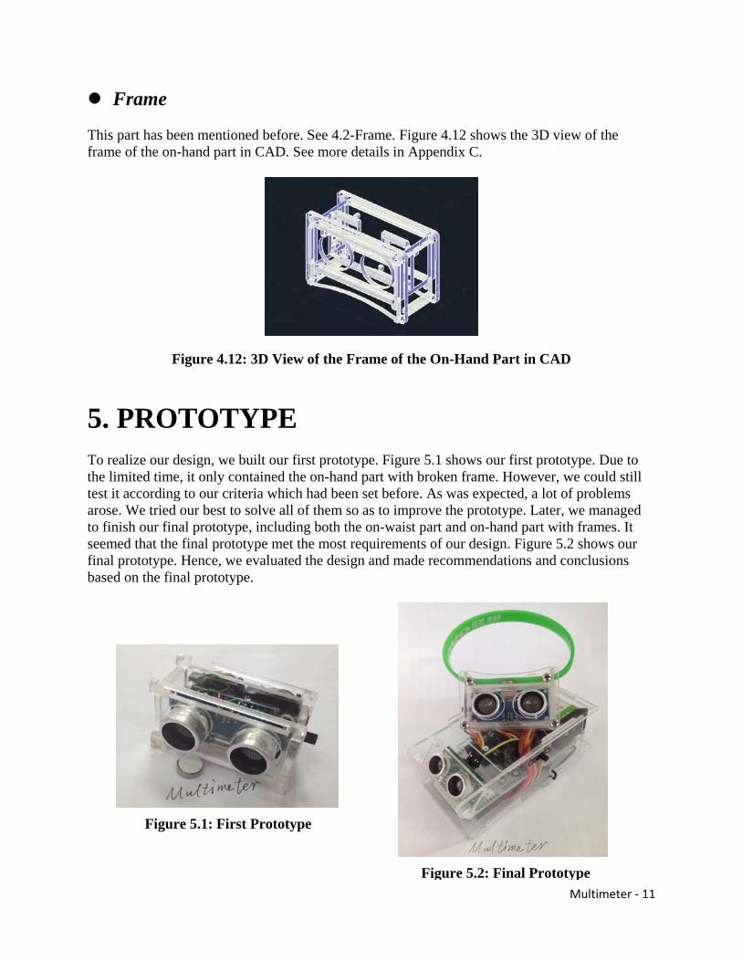
Frame This part has been mentioned before. See 4.2-Frame. Figure 4.12 shows the 3D view of the frame of the on-hand part in CAD. See more details in Appendix C.
Figure 4.12: 3D View of the Frame of the On-Hand Part in CAD
5. PROTOTYPE To realize our design, we built our first prototype. Figure 5.1 shows our first prototype. Due to the limited time, it only contained the on-hand part with broken frame. However, we could still test it according to our criteria which had been set before. As was expected, a lot of problems arose. We tried our best to solve all of them so as to improve the prototype. Later, we managed to finish our final prototype, including both the on-waist part and on-hand part with frames. It seemed that the final prototype met the most requirements of our design. Figure 5.2 shows our final prototype. Hence, we evaluated the design and made recommendations and conclusions based on the final prototype.
Figure 5.1: First Prototype
Figure 5.2: Final Prototype

Multimeter - 12
6. EVALUATIONS This section presents the results of our final prototype tests. There are three parts in our prototype tests: measure the accuracy of the on-waist device to detect the obstacles ahead, the accuracy of the on-waist device to detect the pit ahead, and the accuracy of the on-hand device to detect the obstacle around the user.
6.1 On-Waist Part The on-waist device is used to detect the obstacles, such as a wall or the stairs upwards, in front of the user. In this part, we tested the accuracy of the on-waist device to detect the obstacle and pit on front of the user.
6.1.1 Measure the accuracy of detecting obstacles ahead In this part, we had measured the accuracy of the on-waist device to detect the stairs upwards in front of the user. As you can see in Figure 6.1, when the height of the stair is 10cm, the error is about 60%. The error decreases with the increase height of the stair. When the height is 50cm, the error rate can be finally controlled lower than 10%. The error can be controlled between 3%~1% when the height of the stair is higher than 60cm. See more details in Appendix D.
Figure 6.1: Error Rate of Detecting Obstacles Ahead
6.1.2 Measure the accuracy of detecting a pit ahead
We had measured the accuracy of the on-waist device to detect a pit in front of the user. As in Figure 6.2, when the depth of the pit is 10cm, the error rate is about 50%. After the height is about 25cm, the error can be controlled lower than 10%. The error is lower than 5% when pit is deeper than 30cm. See more details in Appendix D.
Multimeter - 13
Figure 6.2: Error Rate of Detecting a Pit Ahead
6.2 On-Hand Part The on-hand device is used to detect obstacles around the user. This device plays a helping role in the two-part device.
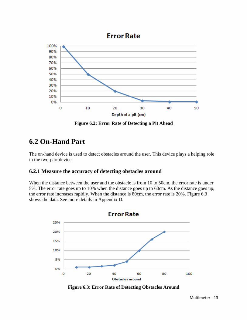
6.2.1 Measure the accuracy of detecting obstacles around
When the distance between the user and the obstacle is from 10 to 50cm, the error rate is under 5%. The error rate goes up to 10% when the distance goes up to 60cm. As the distance goes up, the error rate increases rapidly. When the distance is 80cm, the error rate is 20%. Figure 6.3 shows the data. See more details in Appendix D.
Figure 6.3: Error Rate of Detecting Obstacles Around

Multimeter - 14
7. RECOMMENDATIONS This section will cover the recommendations to those people who are going to use our product, and future developers who are interested in our products.
7.1 To Users
Pre-use practice
It is recommended to practice our devise in a safe location with monitoring before actually using it. Our devise works in a curtain method, and only after practice, will the user be able to handle our devise competently, and hence ensure his or her safety.
Regular battery replacement
Although a fully charged battery can support at least eight-hours-long work of our devise, it is still important to replace the battery regularly. Otherwise, due to long time usage, the dangerous case in which the battery dies out while the user is still walking outside may occur.
Staying alert
Our device is just an ancillary tool. It is impossible to handle all the situations which may happen on the road, so the user still needs to stay alert outside.
7.2 To Designers
Better alarm
So for our design only contain the alarm of sounds like numbers and high or low, however it very inefficient to use these sound, and boring to hear them. If possible, a more efficient and friendly way of alarm would be preferred.
Stable construction
Considering the fact that the devise is hanged on the waist and hand, it is clear that the devise will be moving all the time. This means that a stable construction is needed. In order to achieve this, high quality processor and sensors, impact reduction framework, and high strength shell is required.
Special obstacles
So far the design is only able to detect normal obstacles such as walls and stairs. However, it requires a more powerful obstacle distinguish system to deal with the complex which may happen. For example, the new design needs to be able to detect a doorsill which may cause

Multimeter - 15
falling, and to distinguish a door curtain which can go through from a solid wall. To achieve this, high accuracy sensors are needed.
Location and direction
To a blind people, knowing his location and direction is very important, because he cannot tell them by observation the surrounding scene. However, due several limits, we fail to add these functions to our product. It is strongly recommended to add these functions.
8. CONCLUSION Our design reaches some goals we have set. First it is convenient to carry. The total weight of our product is less than 500 grams. The on hand part, and on waist part can be easily fixed onto human body by a tie and a cramp. Second, it is easy to use. All the user has to do is to put on the device and turn on the switch. Third, by summing up the using time in tests, the result shows that the device can work for at least 8 hours for a single battery. Fourth, when the danger is detected, the device can make the alarm correctly. It is a success in these respects.
However, we fail to fulfill one criterion which is to detect the situation around correctly. So far our design is only able to detect big obstacles, but to other small or special, it fails to work. This problem still needs to be fixed.
To summarize, our design reaches most goals we have set. In addition, our device protects the blinds dignity. They no longer have to bring the blind stick which clearly shows that they are blind. Besides, although our design is not so efficient, it introduces a new concept of using modern technics to help blind people. After further developing, it is possible to put design into industry.

Multimeter - 16
REFERENCES Arduino Team. [date unknown]. Arduino Mega 2560 [Internet]. Arduino web site. [cited in 2013
July 28]. Available from: http://arduino.cc/en/Main/ArduinoBoardMega2560
Arduino Team. [date unknown]. Arduino Pro Mini [Internet]. Arduino web site. [cited in 2013 July 28]. Available from: http://arduino.cc/en/Main/ArduinoBoardProMini
Hsieh. C. (1992). U.S. Patent No 5097856: Electronic Talking Stick for the Blind. Washington, DC: U.S. Patent and Trademark Office.
Jansen. R. J. (1998). U.S. Patent No 5816277: White Stick for Blind Persons. Washington, DC: U.S. Patent and Trademark Office.
Michael Margolis (2011). Arduino Cookbook, second edition. Sebastopol: O’ Reilly Media
Nanayakkara. P. L., Nanayakkara. A. R. & Nanayakkara. L. (2005). U.S. Patent No 6867697 B2: System for Guiding the Visually Handicapped. Washington, DC: U.S. Patent and Trademark Office.
ROBOTC Team. 2012 Aug 15. What is an Ultrasonic Sensor? [Internet]. ROBOTC web site. [cited in 2013 July 28]. Available from: http://www.robotc.net/wiki/Tutorials/Arduino_Projects/Mobile_Robotics/BoeBot/What_Is_An_Ultrasonic_Sensor
WHO. 2010 Nov 22. Blindness as a public health problem in China: Global Initiative for the Elimination of Avoidable Blindness [Internet]. WHO web site. [cited in 2013 July 29]. Available from: http://www.who.int/mediacentre/factsheets/fs230/en/

A – 1
Appendix A: Gantt Chart

A – 2

A – 3

A – 4

A – 5

A – 6

B – 1
Appendix B: Code
On-Hand Part (Arduino Pro Mini): int Trig=8;
int Echo=9;
int OUT=6;
int normalDistance=0;
int cm=0;
void setup()
{
// put your setup code here, to run once:
pinMode(Echo,INPUT);
pinMode(Trig,OUTPUT);
pinMode(OUT,OUTPUT);
Serial.begin(9600);
/*digitalWrite(Trig,LOW);
delayMicroseconds(2);
digitalWrite(Trig,HIGH);
delayMicroseconds(10);
digitalWrite(Trig,LOW);
normalDistance=pulseIn(Echo,HIGH)/58.0;*/
}
void loop()
{
// put your main code here, to run repeatedly:
digitalWrite(Trig,LOW);

B – 2
delayMicroseconds(2);
digitalWrite(Trig,HIGH);
delayMicroseconds(10);
digitalWrite(Trig,LOW);
cm=pulseIn(Echo,HIGH)/58.0;
cm=(int(cm*100.0))/100.0;
Serial.print(cm);
Serial.print("cm");
Serial.println();
if(cm<=60)
{
analogWrite(OUT,255-3*cm);
delay(100);
digitalWrite(OUT,LOW);
delay(50);
}
delay(50);
digitalWrite(OUT,LOW);
}
On-Waist Part (Arduino Mega 2560): unsigned int mm = 0;
int normalDistance[4];
unsigned int HighLen = 0;
unsigned int LowLen = 0;
int count1=0;
int count2=0;
/*void play(int x)

B – 3
{
switch (x){
case 0 :
{
Serial1.println("\\zero\r\n");
break;
}
case 1 :
{
Serial1.println("\\one\r\n");
break;
}
case 2 :
{
Serial1.println("\\two\r\n");
break;
}
case 3 :
{
Serial1.println("\\three\r\n");
break;
}
case 4 :
{
Serial1.println("\\four\r\n");
break;
}
case 5 :
{

B – 4
Serial1.println("\\five\r\n");
break;
}
case 6 :
{
Serial1.println("\\six\r\n");
break;
}
case 7 :
{
Serial1.println("\\seven\r\n");
break;
}
case 8 :
{
Serial1.println("\\eight\r\n");
break;
}
case 9 :
{
Serial1.println("\\nine\r\n");
break;
}
}
delay(700);
}
void makeSound(int x)
{
int a[3];

B – 5
a[2]=x%10;
x=x/10;
a[1]=x%10;
a[0]=x/10;
play(a[0]);
play(a[1]);
play(a[2]);
delay(1000);
}*/
void setup()
{
Serial.begin(9600);
Serial1.begin(19200);
delay(2000);//等待 2 秒钟播放器初始化完成
Serial1.println("\\:v 250\r\n"); // 音量设置最大 数字 0-255 数字越大音量越大
Serial2.begin(9600);
do
{
Serial2.flush();
Serial2.write(0X55);
delay(2);
if(Serial2.available() >= 2)
{
HighLen = Serial2.read();
LowLen = Serial2.read();
normalDistance[1]=HighLen*256 + LowLen;
Serial.println(normalDistance[1], DEC);
}
delay(200);

B – 6
Serial2.flush();
Serial2.write(0X55);
delay(2);
if(Serial2.available() >= 2)
{
HighLen = Serial2.read();
LowLen = Serial2.read();
normalDistance[2]=HighLen*256 + LowLen;
Serial.println(normalDistance[2], DEC);
}
delay(200);
Serial2.flush();
Serial2.write(0X55);
delay(2);
if(Serial2.available() >= 2)
{
HighLen = Serial2.read();
LowLen = Serial2.read();
normalDistance[3]=HighLen*256 + LowLen;
Serial.println(normalDistance[3], DEC);
}
delay(200);
}while(normalDistance[1]<800||normalDistance[1]>1500||normalDistance[2]<800||normal
Distance[2]>1500||normalDistance[3]<800||normalDistance[3]>1500);
//normalDistance=950;
normalDistance[0]=(normalDistance[1]+normalDistance[2]+normalDistance[3])/3;
Serial1.println("\\zero\r\n");
Serial.print("normalDistance is: ");
Serial.print(normalDistance[0], DEC);

B – 7
Serial.println("mm");
}
void loop() {
Serial2.flush();
Serial2.write(0X55);
delay(2);
if(Serial2.available() >= 2)
{
HighLen = Serial2.read();
LowLen = Serial2.read();
mm=HighLen*256 + LowLen;
}
else mm=normalDistance[0];
if (mm<=normalDistance[0]-150)
{
count1++;
if (count1>3)
{
Serial1.println("\\:v 255\r\n");
Serial1.println("\\high\r\n");
delay(600);
Serial1.println("\\:p\r\n");
Serial.println("alarm");
//makeSound(mm);
}
}
else count1=count1/2;
if(mm>=normalDistance[0]+200)
{

B – 8
count2++;
if (count2>5)
{
Serial1.println("\\low\r\n");
delay(600);
Serial1.println("\\:p\r\n");
Serial.println("alarm");
}
}
else count2=count2/2;
Serial.print("Present Distance is: ");
Serial.print(mm, DEC);
Serial.println("mm");
delay(70);
}

C – 1
Appendix C: CAD Drawing
On-Waist Part:

C – 2
3D View of On-Waist Part:

C – 3
On-Hand Part:
C – 4
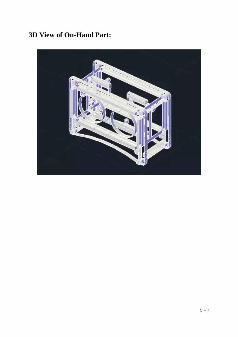
3D View of On-Hand Part:

D – 1
Appendix D: Test Data There are three parts in our prototype tests: measure the accuracy of the on-waist device to
detect the obstacles ahead, the accuracy of the on-waist device to detect the pit ahead, and the
accuracy of the on-hand device to detect the obstacle around the user.
On-waist part
The on-waist device is used to detect the obstacles, such as a wall or a upstairs, in front of the user. In this part, we tested the accuracy of the on-waist device to detect the obstacle and pit on front of the user.
Measure the accuracy of detecting obstacle ahead:
In this part, we had measured the accuracy of the on-waist device to detect a upstairs in front of the user. As you can see on figure D – 2, when the height of the stair is 10cm, the error is about 60%. The error decreases with the increase height of the stair. When the height is 50cm, the error rate can be finally controlled under 10%. The error can be controlled between 3%~1% when the height of the stair is higher than 60cm.
Figure D – 1: Initial Data of Detecting Obstacle Ahead

D – 2
Figure D – 2: Error Rate of Detecting Obstacle Ahead
Measure the accuracy of detecting a pit ahead:
We had measured the accuracy of the on-waist device to detect a pit in front of the user. As in Figure D – 4, when the depth of the pit is 10cm, the error rate is about 50%. After the height is about 25cm, the error can be controlled under 10%. The error is lower than 5% when pit is deeper than 30cm.
Figure D – 3: Initial Data of Detecting a Pit Ahead

D – 3
Figure D – 4: Error Rate of Detecting a Pit Ahead
On-hand part
The on-hand device is used to detect obstacles around the user. This device plays a helping role in the our two-part device.
Measure the accuracy of detecting obstacles around
When the distance between the user and the obstacle is from 10 to 50cm, the error rate is under 5%. The error rate goes up to 10% when the distance goes up to 60cm. As the distance goes up, the error rate increases rapidly. When the distance is 80cm, the error rate is 20%. Figure D – 6 shows the data.

D – 4
Figure D – 5: Initial Data of Detecting Obstacles Around
Figure D – 6: Error Rate of Detecting Obstacles Around

E – 1
Appendix E: WHO Report
Blindness as a public health problem in China
Global Initiative for the Elimination of Avoidable Blindness
Fact sheet N°230 China accounts for about 18% of the world's blind. The country is estimated to have the largest number of blind people in the world – around 5 million. By definition, these people cannot walk about unaided. Against the background of a huge population, estimated by the UN at some 1267 million people, these figures do not look impressive. Indeed, the current prevalence of blindness in China – the total number of blind people at any given time expressed as a percentage of the total population -- is around 0.4%. However, in absolute terms, the country's ever-increasing blind population has already surpassed the total population in such countries as Denmark, Finland or Norway. In China, blindness is not only a public health and social problem. Apart from the unspeakable suffering and hardship that it has brought upon these millions of people and their immediate families, this condition is a serious drain on the national economy. However, any attempt to arrive at the total direct and indirect costs of blindness to the Chinese economy will be guesswork. Such statistics do not exist in the country. For comparison, in 1990, the total cost of blindness to the federal budget in the USA was estimated to be around US$4.1 billion. It was also estimated that if all the avoidable blindness in persons under 20 and working-age adults were prevented, a potential saving of US$1.0 billion per year would accrue to the federal budget. In a study from India in 1989, such costs, including a minimal subsistence allowance for the blind, were estimated at some US$4.6 billion per year. Globally, the aggregated costs of blindness to the world economy were put at some US$25 billion.
Causes of blindness

E – 2
The major causes of blindness in China include cataract, cornea diseases, trachoma, glaucoma and a number of factors contributing to blindness in children. The main cause of blindness in China today is cataract -- a condition that refers to a clouding of the crystalline lens of the eye. It is predominantly a disease associated with ageing. Cataract is responsible for approximately 50% of the country's blind, or around 2.5 million people. Each year, around 400 000 people become totally blind because of cataracts alone. Trachoma is still endemic in certain parts of China. Of the thirty-one provinces in the country, the disease is reported in eight. Trachoma blindness prevalence of 0.1% is reported in the Henan Province. The disease is the second cause of blindness after cataract in the Shandong Province and the third one in the Hunan and Yunnan Provinces. It is also considered a public health problem in the Fujian and Hebei Provinces. Trichiasis surgeries are still performed in the Anhui and Gansu Provinces. Blindness in Chinese children is mainly caused by vitamin A deficiency, measles, conjunctivitis in the newborn, congenital cataract and retinopathy of prematurity(ROP). Of an estimated 1 million blind children in Asia, some 400 000 probably live in China. According to the UN and WHO, vitamin A deficiency remains a public health problem in China. It will remain so even after the year 2000 – the target year for the elimination of blindness resulting from vitamin A deficiency, which was ambitiously set by the World Summit for Children in 1990. ROP blindness is emerging as a problem in the country because of the ever-increasing survival of low and very low birth weight infants.
National efforts
In 1949, when the Peoples' Republic of China came into existence, the principal causes of blindness were infectious eye diseases (mainly trachoma), vitamin A deficiency, trauma and glaucoma. The prevalence of trachoma – a disease associated with poor housing, sanitation and hygiene -- was as high as 50%, reaching 90% in remote rural areas of China. From its inception the new State and the national authorities at all levels made great efforts to prevent and treat trachoma, which was declared a public health priority. Ophthalmologists throughout the country responded enthusiastically and actively participated in these nationwide efforts. As a result, in the 1960's the prevalence and severity of trachoma was significantly reduced throughout the country. However, during the ten years of the Cultural Revolution, blindness prevention efforts in China were discontinued. They were reinitiated only in the 1980's.

E – 3
In 1984, blindness prevention in China received a new impetus. The Government established a National Steering Group for the Prevention of Blindness that has subsequently developed a "Nationwide Working Programme for Blindness Prevention and Primary Eye Care, 1991-2000". In 1996, at the initiative of the Ministry of Health, supported by other ministries, June 6 was declared to be the annual National Eye-Care Day, a move that has played a significant role in mobilizing the public at large and national authorities at all levels for blindness prevention. An epidemiological survey in the early 80s was the first to suggest that the principal cause of blindness in China was no longer trachoma but cataracts. Blindness prevention and treatment projects, which focused on screening and surgical intervention for cataracts, were initiated in all parts of the country. The China Disabled Persons' Federation–an influential nationwide organization catering for the needs of an estimated 20 million people with disabilities, began promoting cataract surgery throughout the country. In 1988, the State Council approved the "Five-year Working Programme of Activities for China's Disabled Persons". The Programme set a target of 500 000 cataract surgeries in the five years that followed. The Outline of the "Eighth Five-year Plan of Activities for China's Disabled Persons", approved by the State Council in 1991, stipulated for 600 000 cataract operations between 1991 and 1995. The goal of the Chinese Ministry of Health over the coming years is to reduce the prevalence of blindness in the country to less than 0.3%, i.e. almost by half. Special emphasis in the prevention of blindness in China is placed on improving the quantity and quality of cataract surgeries, as well as on intensifying efforts to avoid eye injuries in the workplace (within an occupational health programme) and among children (within a school health education programme).
Cataract, human resources and eye care delivery
Cataract blindness in China reflects the overall problems the country is facing in the eye care delivery. At present, China has some 126 million people over 60 years of age. The country is also estimated to have the highest growth rate of the elderly population in the world. By 2020, the group of older people is projected to increase by 90% and reach 240 million people. This estimated increase would place China on top of the list of five developing countries that are expected to have the largest elderly populations in the world by 2020.

E – 4
Age-related conditions in China, such as vision loss due to cataract, will increase accordingly if no preventive actions are taken. The Chinese Ministry of Health estimates that if the current trends remain unchanged, the number of people blind from cataract alone will more than double, reaching over 5 million by 2020, while the overall number of China's blind will increase four times. The number of cataract operations per million population per year (Cataract Surgical Rate or CSR) is illustrative of the delivery of eye care in any country. Today, an estimated 360000 cataract operations are performed in China, giving the average national CSR of 290 per million population per year. This rate is higher than in Africa (200) but particularly low if compared to the established market economies, where it ranges between 3000 and 5000. On the other hand, the CSR in China is steadily on the rise. It was estimated to be 136 in 1994 and 192 in 1997. In certain provinces, the CSR is already considerably higher than the average national rate. Lack of adequately trained eye care practitioners seems to be the main bottleneck. There is an estimated 22 000 eye doctors in China, who have different levels of training and experience. About 50% of them practice cataract surgery. This means that the country probably has only around 5-7 cataract surgeons per million population or 1 per 150 000 -- 200 000 population. In addition, the distribution of surgically active ophthalmologists is very uneven. Most of them are found in urban settings, while more than 70% of the population lives in the rural areas. On average, of the 2400 county hospitals scattered throughout the country, 45% do not have a trained cataract surgeon. In some provinces, such as Xinjiang, Tibet and Hunan, this percentage is even higher, often reaching 75%. The situation at the county level is frequently further complicated by the lack of appropriate equipment and supplies. Nevertheless, from 1988 to 1996, an estimated 1.75 million sight-recovering cataract surgeries was performed in China. However, two randomized sample surveys (in the Shunyi District, Beijing, and in the Doumen County, Guangdong Province) carried out in 1996 revealed that in more than 10% of these cases the outcome of the operation was poor. In the operated patients, the sight was either not restored, or they continued to have low vision. The surveys showed that the lower than expected quality of cataract surgery was not an isolated phenomenon. One of the reasons is the lack of practical knowledge about and supply of intraocular lenses, which are successfully used in cataract surgery in developed countries. As a result, the cataract surgical coverage in China chronically lags behind the expected needs by some 80%. The current backlog of urgent cataract cases, which require surgical intervention, exceeds 2 million.

E – 5
International response
WHO has always recognized blindness and visual impairment as a public health problem in many countries, both developed and, particularly, developing. However, for a long time, the magnitude of the problem could not be assessed, and meaningful global and regional prevention activities could not be initiated for lack of epidemiological data. The first task faced by the WHO Programme for the Prevention of Blindness (PBL), created in 1978, was to prepare reliable estimates of prevalence of blindness and visual disability worldwide. In response to this challenge, PBL developed internationally acceptedsimple population assessment methodologies to measure prevalence of visual loss and identify its causes. Standard low-cost field surveys, designed by WHO and conducted mainly by trained non-specialist staff, provided the badly needed epidemiological data and helped arrive at national blindness estimates. On the basis of national data, regional and global estimates were prepared and used in the development of the WHO Global Data Bank on Blindness, an indispensable tool for planning international action to prevent or treat blindness. PBL started its work in China in 1981. It supported and assisted the Chinese health authorities in epidemiological surveys on blindness and its causes in many provinces. As a result of these collaborative efforts, the true picture of blindness in the country began to emerge. In 1986, a WHO Collaborating Centre was established at the Institute of Ophthalmology in Beijing. Thus, the foundation was laid for further collaborative research and training activities. At the same time, in cooperation with leading scientists, institutions and collaborating organizations, WHO continued to develop strategies and technical standards for control of specific blinding diseases. Scientifically sound, field-tested and regularly updated, these strategies were gradually gaining worldwide acceptance. For example, the "SAFE" strategy for the elimination of trachoma is of special relevance to China, where foci of the blinding disease persist in a number of provinces. "SAFE" stands for Surgery for trichiasis (inturned eyelashes), Antibiotics, Facial cleanliness and Environmental improvement. It consists of a combination of public health interventions, which seek community participation and involvement. A WHO Alliance for the Global Elimination of Trachoma (GET 2020) was established in 1997, which constitutes an integral part of Vision 2020.

E – 6
WHO-developed strategies have been adopted by governments, international agencies, nongovernmental development organizations, as well as Foundations in their every-day work to prevent and treat blindness.
Nongovernmental development organizations (NGDOs)
NGDOs have been playing an increasingly important role in blindness prevention worldwide. In developing countries, the NGDO network is currently spending an estimated US$80 million per year on blindness prevention and treatment. At present, there are 12 NGDOs actively collaborating with WHO and the Ministry of Health and supporting eye care delivery in 19 of the 31 provinces in China. Among them (in alphabetical order):
• Amity Foundation (China) • Asia Foundation for the Prevention of Blindness (Hong Kong, China) • Christoffel-Blindenmission (Christian Blind Mission International (CBM), Germany) • Foresight (Australia) • Foundation for Eye Care Himalaya (The Netherlands) • The Fred Hollows Foundation (Australia) • Helen Keller International (USA) • The Lions Club International (USA) • ORBIS International (USA) • Singapore National Eye Centre (Singapore) • Seva Foundation (USA) • Tibet Vision Project (USA)
With rare exceptions, all these NGDOs have agreed to work together within Vision 2020 towards the common goal of eliminating avoidable blindness in China by the year 2020. There are other NGDOs, like Health Hong Kong Foundation, which are working independently with the Ministry of Health. The NDGOs working within Vision 2020 will concentrate on developing model projects for delivery of high-volume, good quality and affordable cataract services and eye care at the county hospital level. Such efforts will require programmes to train Chinese cataract surgeons and provide assistance to the Chinese Ministry of Health and China Disabled Persons' Federation with appropriate equipment and technologies. These organizations will also continue to support the delivery of cataract operations.

E – 7
Training activities will be carried out with emphasis on counties without a cataract surgeon, where trainee ophthalmologists will be identified on the understanding that they will return to work in their own county. A uniform certification of competence for cataract surgery will be developed in consultation with the Chinese Ministry of Health. Some of the NDGOs will continue to be involved in the prevention and treatment of trachoma and vitamin A deficiency.

F – 1
Appendix F: Electronic Talking Stick for the Blind (24-Mar-1992)
Publication Number: US 5097856 Publish Date: 24-Mar-1992
Application Number: US 7/640903 Filing Date: 14-Jan-1991
US Patent Publication (Source: USPTO) Abstract (English) This invention relates to an electronic talking stick for the blind and more particularly to a stick which talks to instruct a blind man to walk and go upstairs and downstairs, and to warn a blind man of dangerous depression in road, and which calls for help when a blind man who uses the stick falls. It is generally comprised of a supporting rod, a control box, a handle, a free steering caster, and a horizontal scanning device, in which the free steering caster helps the whole assembly to slide; two detectors in the control box and a range finder and moving object detector in the handle are arranged for trouble detection to let detected signals be converted into voice, by means of the processing through a control circuit, to instruct the user through an earphone connected to the handle.
Inventors Chi-Sheng; Hsieh Taipei, TW
Classifications International: A61H 3/02 National: 135/72; 135/911; 381/51 Field of Search: 135/72; 135/88; 135/65; [+6]
Patent References US
3158851 Directional obstacle detecting cane for the blind Nov-1964 135/85
US 3546467
Typhlocane with range extending obstacle sensing devices
Dec-1970 135/65
US 3996950
Obstacle detection device for use by the blind Dec-1976 135/85 [+3]
Examiners Primary: Scherbel; David A. Assistant: Mai; Lan
Attorney, Agent or Firm Asian Pacific Int'l Patent and Trademark Office
Inventors

F – 2
CHI-SHENG HSIEH TW
Applicants CHI SHENG HSIEH TW
Priority US 640903 A 14-Jan-1991
Classifications International (2006.01): A61H 3/06; G01S 7/481; G01S 7/483; G01S 17/42 Cooperative (2013.01.01): A61H 3/068; A61H 3/061; G01S 7/4813; [+3]
Patent Family Membership 24570156 simple family Electronic talking stick for the blind
BACKGROUND OF THE INVENTION
The present invention is related to an electronic talking stick for the blind to help a blind man to walk, which utilizes synthetic voice to inform passers or the blind man of the existing situation. It indeed helps to solve the problems a blind man may encounter while carrying a conventional stick or being guided by guide dog.
In U.S. Pat. No. 4,280,204, a cane for the blind provided with an ultrasonic obstacle sensing apparatus is disclosed, wherein a transducer 16 is mounted on shank portion 14 of the cane 10 to transmit and receive a directional, multiple lobe pattern of ultrasonic energy, whereby when an elevated obstacle is detected, an obstacle detection signal is transmitted by an AM transmitter through antenna 86 to an AM receiver 84 where it is heard by visually impaired person 80. The protective zone provided for a cane user with this arrangement is quite limited and the obstacles detected can not be identified to be a passer or a stationary object.
In U.S. Pat. No. 3,546,467, a relatively costly and complex mobility cane utilizing a plurality of aesthetically objectionable, object detecting, coherent (laser) sensor pairs, is described. Highly directional transmitting and receiving sensors are mounted in a spaced relation on the cane shank. The ability to adjust the object sensors to the desired maximum object detection range is dependent upon the ability to mechanically set the angular position of each sensor with respect to the cane shank. Accordingly, an object must actually intersect a relatively narrow light beam in order to be detected and the protective zone is also very limited.
U.S. Pat. No. 2,496,639 discloses a mobility cane employing a pair of ultrasonic energy transmitting and receiving piezoelectric transducers. This particular cane is less complex than the above-mentioned U.S. Pat. No. 3,546,467. However, it suffers all of the shortcomings of the U.S. Pat. No. 2,496,639.
According to the present invention, an electronic talking stick for the blind includes a telescopic supporting rod, a control box, a handle mounted on the supporting rod and a free steering caster mounted under the control box. The handle and the control box are provided with detecting device and processing system to automatically detect road obstructions and convert detected signals into voice to inform the user or the

F – 3
person detected. According to the present invention, the supporting rod is rotatable and telescopic, and the DC power supply is rechargeable.
SUMMARY OF THE INVENTION
It is an object of this intention to provide an electronic talking stick for the blind, which can talk to instruct a blind man to walk and go upstairs and downstairs, and to warn a blindman of dangerous depression in road, and which calls for help when a blind man who uses the stick falls. It is generally comprised of a supporting rod, a control box, a handle, a free steering caster, and a horizontal scanning device, in which the free steering caster helps the whole assembly to slide; two detectors in the control box and a range finder and moving object detector in the handle are arranged for trouble detection, converting detected signals into voice, by means of the processing through a control circuit, to instruct the user through an earphone connected to the handle.
BRIEF DESCRIPTION OF THE DRAWINGS
FIG. 1 illustrates an electronic talking stick embodying the present invention;
FIG. 2 is a perspective view of a control box according to the present invention;
FIG. 3 is a schematic drawing illustrating the structure of a free steering caster according to the present invention;

F – 4
FIG. 4 is a schematic drawing illustrating the structure of a horizontal scanning device according to the present invention;
FIG. 5 is a block diagram of the scanning device of the present invention;
FIG. 6 is a flow chart illustrating a scanning detection signal processing procedure according to the present invention;
FIG. 7 is a circuit diagram of the scanning system of the present invention;
FIG. 8 is a scanning detection signal processing circuit diagram of the present invention;
FIG. 9 is a flow chart illustrating the control process of the present invention; and
FIG. 10 is a flow chart illustrating the horizontal scanning process of the present invention.

F – 5

F – 6

F – 7
DETAILED DESCRIPTION OF THE PREFERRED EMBODIMENT
Referring to FIG. 1, which illustrates an electronic talking stick for the blind embodying the present invention which includes a supporting rod (10), a control box (20), a handle (30), and a free steering caster (40). According to the present invention, the full length of the electronic talking stick is set within 110 cm-150 cm. The supporting rod (10) is telescopic, including two elongated segments controlled by a revolving coupler (11), the full length of which may be flexibly arranged to fit for use by a blindman within 150-180 cm in height. The handle (30) is mounted on the supporting rod (10) at the top and firmly secured thereto by means of a control knob (31) through which the angular position of the handle (30) on the supporting rod (10) may be flexibly adjusted according to user's preference and convenience. A power switch (33) is mounted on the handle to control power supply, and an earphone socket (32) is located on the handle (30) for connection thereto of an earphone (36) to help a blindman to receive voice instruction from the control box (20) while the blindman passes through a noisy environment.
When a user is ready to walk, one may hold the handle (30) with one hand and push the power switch (33) forward to the ON position to connect electric power supply. Immediately after power on, an user will hear a word--"Ready!"--through the earphone (36). Under this condition, if the stick is horizontally placed or suspended in the air and the free steering caster (40) is not in touch with the ground, the control circuit in the control box (20) will judge if the stick is not in use or the user fell to the ground (this will be described further), and a voice--"Pick up your stick, otherwise will call for help 5 seconds later"--will be generated through the earphone (36).
A range finder (34) and a moving object detector (35) are mounted on the handle (30) at the front of which the effective range is respectively set within 1.2 meters. Before starting to walk, one may hold the handle (30) with one hand and turn it around to detect the environment. If a voice--"Obstruction!"--is heard through the earphone (36), one shall have to turn the handle (30) to another direction until the range finder (34) detects a clean target direction for walking. When walking, the moving object detector (35), which is a kind of infrared detector and mounted on the handle (30) at the front below the range finder (34), starts to continuously detect the front environment within a range of 1.2 meters. If any moving object signal is detected, the control box (20), which is connected to the supporting rod (10) at the bottom will generate a voice--"Excuse me, let me pass!".
Referring to FIG. 1 again, the control box (20) (which will be described further in FIG. 2) is connected to the supporting rod (10) at the bottom to bear the total weight of the stick so that a blindman can very conveniently manipulate the stick as shown in FIG. 2, the control box (20) comprises internally a horizontal scanning device (51) and a ground surface detector (70). As shown in FIG. 1, the control box has an external horizontal scanning window (21) and a ground surface detecting window (22) to efficiently detect ground surface condition and any front obstructions while moving. Two acrylic cover boards (23) are bilaterally mounted on the control box (20) with small flash lights respectively set at the inner side for use while walking in the night.
Referring to FIG. 2, a main control case (80) is mounted on the control box (20) internally at the back side having received therein a rechargeable battery and a control processing circuit board. A scanner holder (50) is set inside the control box (20) at the front of the main control case (80) having mounted thereon a horizontal scanning device (51) scanning device secured to a perforated circular aluminum plate (62) (FIG. 4)

F – 8
via the revolving shaft of a DC motor (52). The horizontal scanning device (51) is controlled to make a horizontally reciprocating motion within an angle of 30 degrees, by a scanner controller (60) set at the bottom of the DC motor (52), so as to constantly perform a 30 degrees sector scanning process while moving, and to constantly send scanning signals to the main control case (80) for processing (the control processing process will be outlined in FIG. 4). A charging socket (56) (FIG. 2) is located on the control box (20) at the back side for connection thereto of a battery charger to charge the battery set therein.
FIG. 3 illustrates the structure of the free steering caster (40). The free steering caster (40) is movably secured to the control box (20) at the bottom with the caster holder (41) coupled with a fixture (42), which is mounted on the control box (20) at the bottom, through a bearing (43). Through the effect of the bearing (43), the caster (40) is allowed to steer in all directions by means of the control through the supporting rod. Therefore, a blind man can very easily control the moving of the FIG. 1 electronic talking stick. A spring (45) is set between the fixture (42) and the control box (20). According to the present invention, the total weight of the battery and other component parts set inside the control box (20) is approximately 0.8 kg. Therefore, the load of the control box (20) constantly presses on the spring (45) to trigger the micro-switches (44) to continuously operate (this will be outlined further) and to send normal operation signal to a control processing circuit for processing.
Referring to FIG. 2 again, the ground surface detector (70) of the control box (20) is arranged to detect a range within 0.3 meter, the detecting direction of which is 45 degrees downward to horizontal level so as to constantly detect front ground surface condition at a 45 degrees angle of inclination. The detected signal from the ground surface detector (70) will be sent to a control processing circuit for treatment.
Referring to FIG. 4, the horizontal scanning device (60) is generally comprised of a base (63) for securing thereto of the DC motor (52), an optical sensor (61) mounted on the base (63), a perforated aluminum circular plate (62) coupled with the motor shaft of the DC motor (52) at the top and set at the front of the optical sensor (61) while the horizontal scanning device (51) is coupled with the motor shaft of the DC motor (52) at the bottom (as viewed in inverted FIG. 4). The optical sensor (61) includes a pair of transceivers (611) and (612), to respectively read the information from the data holes (621) and 622 of the aluminum circular plate (62). The data holes (621) are comprised of fifteen holes, while the side holes (622) are comprised of two rectangular holes having approximately double the size of the data holes (621) and being respectively set at both sides of the data holes (621). When in operation, the DC motor (52) will be triggered to revolve reversely immediately after the transceiver (612) receives a signal from either of the side holes (622). Thus, the aluminum circular plate (62) will be driven to make reciprocating motion within a 30 sector plane. During reciprocating motion of the aluminum circular plate (62), an intermittent signal will be resulted from the data holes (621) through the transceiver (611). The intermittent signals from the transceiver (611) as well as the signal detected by the horizontal scanning device (51) are simultaneously sent to a control processing circuit for comparison, analysis and treatment for further judging if there is any obstruction in front of the user. (With respect to the principle of comparison, analysis and treatment please refer to the circuit flow chart.)
Referring to the block diagram of the scanning device 51 of the present invention as shown in FIG. 5. and according to the present invention, the scanning process of the horizontal scanning device (51) is made through infrared ray reflection. It is generally comprised of seven parts as outlined hereunder:

F – 9
Pulse generator (511): to constantly produce a fixed frequency so as to emit a narrow light beam through a diode, and to operate when power supply is connected;
Pulse amplifier (522): to amplifier the weak infrared signal received;
Wave filter-detector circuit (533): generally comprised of a band-pass filter circuit to eliminate noises and to pick up required signal;
Synchronous amplifier-comparator (544): to amplify the main signal picked and to compare the main signal with the frequency transmitted (Because the main signal may be attenuated during posterior filtration process, it must be amplified again for comparison with the frequency transmitted;
Load drive stage (555): because load consumes higher rating, an additional drive is required; and
Reflected radio wave from a reflecting object (100) is sent to the pulse generator (511) and load drive (555) may be connected to external load (566).
Please refer to the scanning system circuit of the present invention as illustrated in FIG. 7. As illustrated, the scanning system circuit is generally comprised of a power supply and a main voltage circuit of relay at load, in which the detecting head is connected to another low voltage circuit at load through a 3-core cable. Because the main circuit is separately received in the box while the detecting head is exposed to the weather, it is very safe in operation. In the scanning circuit as illustrated in FIG. 7, IC71 is a standard Schmitt trigger-oscillator, C72 is from R72, R73 to transistor Q71, and it picks up a small current gain value 50 to drive a 500 mA electric current to emit through an infrared diode TX71, wherein the emitting range may be adjusted through R74 by changing the electric current gain value.
The reflected infrared light beam will be detected by the photodiode RX71. A filter network may be set in front of the light collecting lens to eliminate interference from pulse mode light source such as filament tube, discharging lamp or TV screen. Regular tungsten filament tube may produce infrared radiation, however, it does not make trouble because only weak energy will be resulted during each cycle the tungsten filament is heated and cooled down. The pulse which enters through the photodiode RX71 is a low level pulse and will be treated through a filter circuit composed of resistors R75 and IC72a to attenuate noises and pick up the pulse required. The pulse picked is sent through resistor R77 for dropping process to further be sent to another filter circuit comprised of R78 and IC72b. The former filter circuit is to cut off noisy signal of the front half cycle of the pulse while the latter is to cut off noisy signal of the rear half cycle of the pulse. Therefore, a right pulse can be obtained after passing through the capacitor C75. The right pulse thus obtained is further buffered through reverse stage IC72c and sent to computing amplifier stage IC73. Before going into the computing amplifier state, the pulse will be trimmed through resistor R80, capacitor C77 and C76 to make the wave form more accurate.
IC73a and IC73b are standard computing amplifier. Because the gain value is very high, any weak voltage entry from input end may cause big wave motion at output end. The resistors R81, R82, R83, R84, R85 and R86 form a voltage divider. The biased voltage from the voltage divider is sent to a transistor Q72 via a resistor R87 to control the load L72. The load L72 may vary with the function required.

F – 10
FIG. 6 is a flow chart illustrating the process in treating scanning detection signal according to the present invention. When sensor (611) receives a signal reflected from an object, the reflected signal is immediately sent to decoder (622) for identification. The decoded signal from the decoder (622) is further locked at signal locking circuit (633). During output of locked signal from locking circuit (633), a corresponding speech data is picked up from a memory bank (644) and concomitantly sent to a voice microprocessor (655) for digital-analog conversion. The weak voice pulse thus obtained is further sent to an amplifier (666) for audio frequency amplification and for further output through a speaker (600). The voice from the speaker (600) can thus be received and understood by people. During the process, the power supply (699) is to provide the circuit with required working power, and the counter (677) is to send the signal provided by the voice microprocessor (655) to drive a warning system (688).
FIG. 8 is a scanning detection signal processing circuit diagram of the present invention. The language processor and the speaker of the present circuit will provide an output whenever an obstruction is encountered. For example, when infrared sensor S1 is triggered, a corresponding voice will be provided through the speaker.
IC7 is (74HC147) 10 vs 4 lines priority coder for checking if any triggering signal input, the input terminals of which are respectively connected to the output loads of the infrared sensors S1-S9, and the input terminals connect a 20K resistors R1-R9 to +5 V, for example, when the infrared sensor S1 is not triggered, the logic is 1, and the logic will become 0 when signal is triggered. When the infrared sensor S1 is triggered, IC1 locks the A, B, C, D of the encoder IC7 and simultaneously triggers the flip-flop IC2b. The reverse output terminals Q1-Q4 of the IC1 are respectively connected to the ends A4-A7 of the programmable read-only memory IC3. IC2a is a CD4520 counter the output terminals of which are respectively connected to the ends A0-A3 of the read-only memory IC3 to scan memory area in proper order. As soon as the infrared sensor S1 is triggered, the end Q1 of the flip flop IC2b becomes high potential. Each time NAND gate IC6 produces a pulse wave in negative direction, a pre-determined program is picked up from the programmable read-only memory IC3 and sent to the voice processor IC4 through the input end ALD. For example, when the direction of an obstruction detected is 5 (the DCBA of the IC7 are 0101), a voice of right forward will be provided through the speaker. When a voice is delivered, the end SBY of the voice processor IC4 becomes low potential, and therefore, the NAND gate IC6 will drive the counter IC2a to add by 1 automatically when it is at positive edge. Each voice report must include 1-7 allophones. A 4H and 44H 16 numbering system data will be provided to reset the voice processor after each program is executed, and at the same time, the end 06 of the programmable read-only memory IC3 will become high potential to reset the counter IC2a and the flip-flop IC2b and to further turn the circuit to start status.
Voice amplification is made through a low rating audio frequency amplifier. When audio frequency signal is picked up from the pin Dout of the IC4, it is filtered through a type filter circuit (R7, R8, C6, C7 and C6 form a type filter circuit) to eliminate noises therefrom, and sent to the amplifier IC5 for maximum 200 mw amplification, wherein the capacitor C9 is to change amplified gain, and the well amplified voice is sent through the capacitor C12 to the speaker.
The control process of the present invention is outlined as illustrated in FIG. 9. When power supply is connected, the system is reset to detect if the caster touches the ground due to operation of switches 44 by the weight of the talking stick. If the caster does not touch the ground within 3 seconds, it informs the

F – 11
user--"Pick up the stick or will call for help after 5 seconds" An audio warning will be provided 5 seconds thereafter if the caster is still not in touch with the ground. If the user starts to use the present invention and the caster is pressing on the ground, the range finder 34 and the moving object detector 35 will simultaneously detect if there is any obstructions or moving objects within 1.2 meters. If no signal is detected, the user may keep moving forward. If any obstruction is detected, a voice of "Obstruction!" will be sent through the earphone to inform the user; or a voice--"Please let me pass!" will be provided through the speaker if any moving object is detected. During operation, the ground surface detector 70 keeps detecting ground surface condition through a 45 degree inclination angle, and the horizontal scanning device 51 detects a horizontal area within 1 meter. All detected signals will be converted into corresponding voice to inform the user of the condition of obstructions and the obstructed direction. The light detector is to detect the intensity of outside light and to turn on the flash lights behind acrylic boards 23 under ambient dark conditions.
FIG. 10 is a flow chart illustrating the operation of the horizontal scanning detection of the present invention. When the present invention is in use, the motor counterrevolution switch starts to operate, the horizontal scanning device starts to detect any obstruction, the counter of the control processing circuit board is cleared to zero, and horizontal data holes (total 15 holes) detection switch starts to detect. If any obstruction signal is detected, the counter will add by 1 to report detection result and to record the value of the counter as well as the detection result. Under this condition, if the revolution of the motor does not reach an angle of 30 degrees the system operates to continuously detect obstructions; if the motor reaches an angle of 30 degrees, it changes revolving direction immediately, and the record is analyzed and the result is reported. Then, it returns to start and the result is sent to main control circuit.
The data reading (signal detection) mode of the horizontal scanning device (51) through the aluminum circular plate (62) is outlined hereinafter. Referring to FIG. 4 again, the aluminum circular plate (62) includes 15 data holes (621) divided into left, middle and right regions, i.e. each region includes 5 data holes, wherein the five data holes (1-5) of the left region correspond to the reading range of the data detected from front left area; the middle five data holes (6-10) of the middle region correspond to the reading range of the data detected from the right front area; the five data holes (11-15) of the right region correspond to the reading range of the data detected from the left front area.
If a signal is detected through the fifth hole of the left region as well as the first hole of the right region, the signal is immediately sent to the control processing circuit board for processing and it is meant that an object is detected at the front left area. If a signal is detected through three holes concomitantly, it is recognized that a big obstruction is detected. If a signal is detected only through one single hole, it is meant that the size of the obstruction is too small to interfere with walking. According to the present invention, the horizontal scanning device is designed to detect a range within 1 meter, which range will be sufficient for a blind-man to turn one's walking direction.
Having shown and described a preferred embodiment of the present invention by way of example, it should be realized that structural changes could be made and other examples given without departing from either the spirit or scope of this invention.
(Source: USPTO)

G – 1
Appendix G: White Stick for Blind Persons (06-Oct-1998)
Publication Number: US 5816277 Publish Date: 06-Oct-1998
Application Number: US 8/875065 Filing Date: 25-Jun-1997
US Patent Publication (Source: USPTO) Abstract (English) The invention relates to a white stick with a transmitter for emitting directed signals, a receiver for receiving signals which are reflected by an object and with display means for converting received signals into an indication which is perceptible by the user of the white stick. The display means includes an at least partially ring-shaped element extending around the white stick and which through a motor is rotatable around an axis which substantially coincides with the centerline of the white stick, wherein the plane in which said ring-shaped element is positioned encloses an angle with said axis differing from 90.degree.. It is possible that the ring-shaped element is at least partially housed in a recess provided in the surface in the white stick.
Inventors Jansen; Reindert Jan Baarn, NL
Assignees Techn-O-Tape, BV NL
Priority NL 1001500 25-Oct-1995
Classifications International: A45B 7/00 National: 135/65; 135/911; 135/66 Field of Search: 135/65; 135/66; 135/911; 135/910
Patent References US
3546467 Typhlocane with range extending obstacle sensing devices
Dec-1970 135/65
US 4280204
Mobility cane for the blind incorporating ultrasonic obstacle sensing apparatus
Jul-1981 135/911
US 4648710
Blind guide device Mar-1987 135/911 [+6]
PCT Filing

G – 2
Filed: WO PCT/NL96/00411 22-Oct-1996 Published: WO WO97/15265 01-May-1997 US 371 (c)(1)(2)(4) Date: 22-Sep-1997
Examiners Primary: Mai; Lanna
Attorney, Agent or Firm St.Onge Steward Johnston & Reens LLC
Inventors JANSEN REINDERT JAN NL
Applicants TECHN O TAPE BV NL
Priority NL 1001500 A 25-Oct-1995 [+1] Classifications International (2006.01): A61H 3/06 International: A45B 7/00 Cooperative (2013.01.01): A61H 3/068; A61H 3/061; A61H 2003/063; Y10S 135/911
Patent Family Membership 19761753 simple family White stick for blind persons
The invention relates to a whitestick with a transmitter for emitting directed signals, a receiver for receiving signals which are reflected by an object and with display means for converting received signals into an indication which is perceptible by the user of the whitestick.
As is well known a whitestick is an essential auxiliary means for blind or partially sighted persons during orienting. However, a disadvantage of the known whitestick is that its reach is limited. For solving this problem attempts have been made in the past to offer an increased "reach" to a partially sighted or blind person. Thus the whitestick was provided with a transmitter and a receiver, whereby received signals were converted into a perceptible indication. Among others, examples of such known whitesticks can be found in Austrian patent specification 355.099 describing a whitestick which is provided with vibration means positioned in the handle, and in German Gebrauchsmuster 9300256, from which a whitestick is known comprising a plate which can be put into vibration.
Also Dutch patent application 93.01911 any United States and foreign patent as may issue therefrom being incorporated herein by reference thereto, in the name of applicant relates to a whitestick of the type referred to above, in which the perceptible indication is realised by means of a notch projecting to a more or less extent.
These known whitesticks have several drawbacks. The constructions and control means which are required for obtaining the desired result are often complicated and thus expensive. Further the whitesticks require a lot of (electrical) energy, thus that their operation time is very limited.

G – 3
It is an object of the present invention to provide a whitestick of the present type which does not show these disadvantages.
Thus the whitestick according to the invention is characterised in that the display means comprise an at least partially ring-shaped element extending around the whitestick and which through a motor is rotatable around an axis which substantially coincides with the centerline of the whitestick, wherein the plane in which said ring-shaped element is positioned encloses an angle with said axis differing from 90.degree..
Because the ring-shaped element is positioned in a plane enclosing an angle with the axis of rotation differing from 90.degree., a rotation of the ring-shaped element around said axis of rotation creates a change of the distance between the ring-shaped element and a defined fixed point at the circumference of the whitestick, such as for example a hand of the user at that position. Thus, during a rotation of the ring-shaped element, the user as it were feels a movement of said ring-shaped element into forward or backward direction, like this obtaining the desired perceptible indication of the distance towards an object registrated by means of the transmitter and receiver.
The construction of the whitestick according to the invention is extremely simple. Further already a small rotation of the ring-shaped element leads to a clearly perceptible variation of the position of said element. Such a small rotation only needs little energy, such that the whitestick has a long period of operation when using batteries.
With respect to the construction of the ring-shaped element a number of possibilities exist. A simple embodiment is characterised by the fact, that the ring-shaped element is anchor-shaped. In this embodiment both legs of the anchor together define a ring segment which follows the circumference of the whitestick. The neck of the anchor defines the connection between said ring segment and the axis of rotation.
However it is possible too that the ring-shaped element is a complete ring fully encircling the whitestick. Of course said ring is connected with the axis of rotation by means of a connecting part. The advantage of this embodiment is, that a damaging of the ring shaped element and the entrance of pollutions into the whitestick is almost completely excluded.
Further it is advantageous, that the ring-shaped element is at least partially housed in a recess provided in the surface of the whitestick. Like this the ring-shaped element is largely protected against external influences, whereas nevertheless the user can clearly feel the movement of the ring-shaped element. Further it is a result of such a partially protected positioning of said ring-shaped element that the counter force exerted onto the ring-shaped element by the user is minimised, such that the energy consumption of the whitestick is further decreased.
Further a special embodiment should be mentioned, according to which the ring-shaped element is mounted directly onto the outgoing shaft of the motor. Like this the energy consumption can be limited to an absolutely minimised value. For, to obtain a displacement of the ring-shaped element the rotation of the motor is limited to a fraction of a complete revolution.

G – 4
Finally control-wise it is preferred that with the motorshaft there is also connected a magnet which cooperates with a Hall-sensor for indicating and controlling the angle of rotation of the motor.
Hereinafter the invention will be elucidated referring to the drawing in which a number of embodiments of the whitestick according to the invention are illustrated.
FIG. 1 shows schematically and in cross section a part of a first embodiment of the whitestick according to the invention;

G – 5
FIG. 2 shows a top plan view of the whitestick illustrated in FIG. 1.;
FIG. 3 shows the ring-shaped element applied in the whitestick according to FIG. 1;
FIG. 4 shows an alternative ring-shaped element, and
FIG. 5 shows a detail of a further embodiment of the whitestick according to the invention.
FIG. 1 shows in cross section and schematically part of a whitestick according to the invention. Housed therein is a transmitter 1 for emitting directed signals and a receiver 2 for receiving signals which are reflected by an object. Through lines not shown the transmitter 1 and receiver 2 are connected with a processing unit not shown either which, depending upon the signals received, controls a motor 3. The outgoing shaft 4 of the motor 3 coincides with the centerline 5 of the whitestick 6. A partially ring-shaped element 7 is mounted onto the outgoing shaft 4. This ring-shaped element 7 may be shaped in different ways, for example in correspondence with FIG. 3 as an anchor or in correspondence with FIG. 4 as a complete ring.
As appears clearly from FIG. 2 the ring-shaped element 7 extends in a plane which encloses an angle with the outgoing shaft 4 or centerline 5, respectively, differing from 90.degree.. Thus a rotation of the ring-shaped element 7 around shaft 4 will lead to an apparent displacement of the ring-shaped element 7 in longitudinal direction of the whitestick 6 relative to a fixed position thereof or, as indicated, relative to a finger 8 of the user positioned thereon. Thus, starting from the starting position 7 of the ring-shaped element represented in FIG. 2 a rotation towards position 7' will lead to an increase of the distance between the ring-shaped element and the finger 8, whereas otherwise a rotation towards position 71" leads to a decrease of said distance. This changing distance provides for an indication which is perceptible by the user and which is a measure of the distance to a registrated object as determined by the transmitter 1, the receiver 2 and not-illustrated processing unit.
In the shown embodiment the ring-shaped element 7 is directly mounted onto the outgoing shaft 4 of the motor 3, such that the motor 3 only needs to rotate over a small angle. As a result the energy consumption is extremely low.
In order to be able to indicate or control, respectively, the angle of rotation of the motor 3, further in correspondence with the shown embodiment a magnet 9 is attached to the outgoing shaft 4, which magnet cooperates without contact with a Hall-sensor 10 indicated only schematically. Of course also potentiometers can be used for this goal, but this leads to an increase of friction in the system and thus to an increase of energy consumption.
Finally FIG. 5 shows a special embodiment of the whitestick according to the invention, at which in the surface of the whitestick 6 a recess 11 is shaped which at least partially houses the ring-shaped element 7. Like this the ring-shaped element 7 is protected against damage, whereas further the entrance of pollution is limited to a minimum. Further this embodiment has the disadvantage that the force exerted onto the ring-shaped element 7 by a finger 8 or the like is small, such that the energy consumption of the whitestick for rotating the ring-shaped element 7 is minimised. Nevertheless the motion of the ring-shaped element 7, especially the increase or

G – 6
decrease, respectively, of its distance towards the finger of the user is readily perceptible by the user. Possibly an appropriate profile may be provided on the ring-shaped element 7 in this context.
The invention is not limited to the embodiment described before which can be varied widely within the scope of the invention as defined by the claims.
(Source: USPTO)

H – 1
Appendix H: System for Guiding the Visually Handicapped (15-Mar-2005)
Publication Number: US 6867697 B2 Publish Date: 15-Mar-2005
Application Number: US 10/112668 Filing Date: 01-Apr-2002
US Patent Publication (Source: USPTO) Abstract (English) A system for guiding of the visually handicapped includes a continuous electrical conductor, in the nature of a wire or strip, having a substantially uniform conductivity embedded within a walkway to be traversed by the handicapped person. The system also including a proximity for detecting the conductor in which the detector may be in a shoe of the user or a tip of a walking cane. The system further includes a signalling element, in the nature of a vibrator, in electrical communication with the detector such that, through the presence of such vibration, the visually handicapped person is able to determine his proximity to the electrical conductor to determine that he is proceeding in a proper direction within or along the walkway. The signalling element is preferably provided with a switch, for example, a mercury switch, so that the shoe or cane circuit will become energized only upon the occurrence of movement or motion of the shoe or cane within which the proximity detector is located. The approach by a user to a location of interest along the walkway, such as an intersection, bathroom, or Braille telephone, may be indicated through the provision of a pattern of irregularity of the conductivity within the continuous electrical conductor. Different patterns of irregularity may indicate different advisories to the user.
Inventors/Applicants Nanayakkara, Pravin L. [+2] Boca Raton, FL, US
Classifications International: G08B 23/00 National: 340/573.1; 340/407.1; 340/825.19 Field of Search: 340/573.1; 340/573.4; 340/407.1; [+8] Patent References
US 3718896 A
Guiding devices Feb-1973 340/573.1
US 4025922 A
Traffic control system May-1977 340/407.1 X
US 4095214 A
Electronic monitoring system and responder device
Jun-1978 340/573.1 [+9]
Prior Publications

H – 2
US 2003/0184441 A1
System for guiding the visually handicapped 02-Oct-2003
Examiners Primary: Mullen, Jr., Thomas J
Attorney, Agent or Firm Silverman, M. K.
Inventors NANAYAKKARA PRAVIN L [+2] US
Priority US 112668 A 01-Apr-2002
Classifications International (2006.01): A61H 3/06; G08G 1/005; G09B 21/00 International: G08B 23/00 Cooperative (2013.01.01): A61H 3/068; A61H 3/061; A61H 3/066; [+4] Patent Family Membership 28453403 simple family System for guiding the visually handicapped
BACKGROUND OF THE INVENTION
1. Area of Invention
The invention relates to guiding devices for use by persons including, but not limited to, the blind, visually impaired, security personnel, emergency personnel and fire fighters.
2. Prior Art
Guiding devices have been designed in which a signal is sent out from the device and is reflected from an object positioned above the walking level and returned to the device, this in the manner of a simplified type of radar or sonar to thereby operate a signalling means to indicate to the user that an object is in front of him. Systems of this type have, however, proven unsatisfactory due to difficulty in the interpretation of the types of signals returned in which a user can often confuse background objects with objects that are in the foreground. Such prior art is reflected in U.S. Pat. No. 3,360,775 (1967) to Schroeder.
A later device of this type is reflected in U.S. Pat. No. 3,718,896 (1973) to Moat in which, provided within a blindman's cane is a transmitter that transmits pulses of energy in a directional manner and a receiver which accepts the first or earliest returned pulses, rejecting all others for a predetermined period. Thereby, only those pulses relative to objects which are in the foreground are processed by the system.

H – 3
More sophisticated systems, such as that reflected in U.S. Pat. No. 4,660,022, involve the use of sound generators selectably positioned at different locations, typically within corridors of a building or shopping mall in which a signal from the cane will actuate the sound generator to convey important information to the blind person, such as “intersection approaching,” “bathroom approaching,” or any other information deemed important for a blind person to obtain when in public places such as pedestrian crossings, railroad stations, airports, and passageways within public buildings. This approach however requires the positioning of such sound generators at numerous places within the public area or space of interest.
In recent years, the above has been improved upon through such approaches as radio-frequency guidance system for visually handicapped, as are reflected in U.S. Pat. No. 5,144,294 (1992) to Alonzi, et al, and U.S. Pat. No. 6,097,305 (2000) to Im, et al. Also, prior art of more recent vintage teaches complete electronic autorouting or navigation systems for the blind, as is reflected in U.S. Pat. No. 5,806,017 (1998) to Hancock, in which the entire routing or itinerary of a visually impaired person may be programmed at the beginning of a trip or may be programmed on a daily, weekly, or task-by-task basis.
The prior art, as reflected in the above, is unquestionably of great value to the visually impaired person if he is fortunate enough to live or work within an area which is able to afford systems of such sophistication.
Also, a further shortcoming of such prior art is that the visually handicapped person is readily identifiable as such by reason of the requirement that he at all times make use of a cane or the like. Thereby, the present invention seeks to address both the issue of cost and, particularly, the issue of social stigma attached to the use of a cane by a person who becomes visually impaired due to illness, accident, or physical condition later in life. Accordingly, within the present invention addresses an alternative to the historic need for use of a cane by blind persons or others having impediments in their mobility or recollection of how to navigate from one point to another.
SUMMARY OF THE INVENTION
The instant invention relates to a system for guiding of the visually handicapped including emergency personnel such as firemen and first aid staff in poorly lit passages which includes two continuous electrical conductors, in the nature of a wire or strip, having a substantially uniform conductivity, the same embedded within a walkway to be traversed by the handicapped person. The system also includes means for detecting proximity of a user to said conductors in which said means may be in the shoes of the user or a tip of a walking cane. The system further includes signalling means, in the nature of a vibrator, in electrical communication with said detecting means such that, through the presence of such vibration, the visually handicapped person is able to determine his proximity to the electrical conductors and, thereby, that he is proceeding in a proper direction within or along said walkway. The signalling means is preferably provided with a switch means, for example, a mercury switch, such that the circuit will become energized only upon the occurrence of movement or motion of the object within which the proximity detecting means is located. The approach by a user to a location of interest along the walkway, such as an intersection, bathroom, Braille telephone, or information counter may be indicated through the provision of a

H – 4
pattern of irregularity of the conductivity within said continuous electrical conductor. Different patterns of irregularity may indicate different advisories to the user. Also, varying the number of electrical conductors embedded, may identify and indicate different information to the user.
It is accordingly an object of the present invention to provide a guiding device for the visually handicapped, due to blindness or an environmental conditions such as lack of illumination, fog, smoke or the like to obviate the need for a walking cane or, alternatively, if a walking cane is employed, enhance the ease of use thereof to effect efficient navigation between points within areas and structures both public and private.
It is another object to provide a system of the above type to render blind persons less obvious when they are in public places.
It is a further object of the invention to provide a system and method for alleviating the uneasiness of visually impaired persons when they are seeking to reach destinations within areas that they are otherwise unfamiliar with.
It is a yet further object to provide a system of the above type having particular value to visually handicapped and other persons subject to forms of disorientation when they are walking in locations, both public and private, such as post offices, banks, schools, shopping malls, supermarkets, bus stops, taxi stands, railroad stations and airports and information centers. Such information centers may provide locations of important places with directions from pre-recorded audio messages available at a press of a button.
It is another object to provide a system for guiding of the blind that may be incorporated fully within an article of clothing, such as a shoe, of the user, thereby eliminating entirely the need for use of a walking cane.
The above and yet other objects and advantages of the present invention will become apparent from the hereinafter set forth Brief Description of the Drawings, Detailed Description of the Invention and claims appended herewith.
BRIEF DESCRIPTION OF THE DRAWINGS
FIG. 1 is a top schematic view showing the locations within which continuous electrical conductors, in accordance with the invention, are provided within walkways of selected building and structure.

H – 5
FIG. 2 is an enlarged view of the indicated part of FIG. 1.
FIG. 3 is a vertical cross-sectional view taken through the floor of the walkway of FIG. 1 showing a positioning of two conductors, such that one or both conductors may be sensed by a sensor within in a shoe or cane.
FIG. 4 is a vertical schematic partial breakaway view showing a shoe which has been provided with an electrical proximity sensor in accordance with the invention.
FIG. 5 is a bottom schematic breakaway view of the shoe of FIG. 4.

H – 6
FIG. 6 is a schematic view of a walking cane that has been provided with sensing and signalling means in accordance with the invention.
FIG. 7 is an enlarged view of the upper portion of another embodiment of the invention.
FIG. 8 is an electrical block diagram of a conductor proximity sensor that may be used with the present invention.

H – 7
FIG. 9 is a schematic view of an arrangement of conductors in which the walkway of FIGS. 1-3 is linear.
FIG. 10 is a view similar to that of FIG. 9 in which the walkway is curved.
FIG. 11 is a schematic view of a conductor arrangement in which a corner or turn of the walkway occurs.
FIG. 12 is a schematic view of a double lane linear walkway.

H – 8
FIG. 13 is a schematic view for a T-intersection of walkways.
FIG. 14 is a schematic view for a four-way in intersection of walkways.
DETAILED DESCRIPTION OF THE INVENTION
With reference to the overhead schematic view of FIG. 1, there may be seen a plurality of walkways 10 which may comprise walkways within public or private structures, residences, or walkways within an outdoor area, e.g., a downtown section of a city street. Embedded within each walkway or applied at substantially the surface thereof is a continuous electrical conductor 12 of substantially uniform electrical conductivity. See enlarged schematic view of FIG. 2. It has, in a preferred embodiment, been found that parallel pairs of metal conductors 12 will afford redundancy for purposes of the invention and will also enlarge the range of conductive material detecting means, as is set forth below.
Such sensors, and proximity sensors in general, operate upon a principle of response to changes in capacitance or inductance when introduced into a field 14 of a probe 15. See FIG. 3. When the necessary range setting of the probe is met, an alarm will trigger within a particular distance from the probe 15 and as the field 14 of the probe is changed, i.e., upon closing movement of the probe towards the metal conductor 12, respective changes in capacitance or inductance will occur unbalancing a set bridge circuit, described below. The bridge output is then passed through a signal amplifier which in turn will operates as audio or other alarm.
The strength of the signal received by the sensor is related to the distance between the sensor probe 15 and conductors 12, positioned on or in the walkway 10. The detectors will produce an output signal at or less than a specific distance between the sensor probe and conductors thereby producing said local pattern or field 14 of capacitive or inductive density as may be seen in the vertical cross-sectional view of FIG. 3. If there is no variation in field density produced by the excitation signal, the detector will produce a constant output which may be used to power any annunciation means such as a vibrator. However, if the proximity sensor drifts from the pathway defined by conductors 12, a change in the field pattern will occur, causing the eventual collapse

H – 9
thereof if the probe 15 is moved too far away from conductors 12. This change in output can be utilized to produce a warning signal to the user.
Applying the above principles to the instant invention, a sensor or conductor detecting means 16 is placed within a forward most portion of a shoe18. See FIGS. 4 and 5. From said sensor 16 is produced the above-referenced excitation signal 20 from which field 14, about conductor 12, is produced. Through wires 22, sensor 16 is in electrical communication with signalling means 24 in the nature of a vibrator 26, such that a user of the system is advised that he is correctly navigating walkway 10.
Also shown in FIG. 4 is a battery pack 28 which, like signalling means 24, is embedded within heel 30 of shoe 32. Further shown therein is an on-off switch 34 by which a user may turn off the entire system if he is either not using shoe 32 or is in a location not provided with conductors 12 of the present invention. The above elements are shown in bottom breakaway view in FIG. 5. It should be further noted that battery a pack 28 may be provided with a motion detector, such as a mercury switch 42, so that the circuit of FIGS. 4 and 5 is closed and, thereby, the system activated, only in the event of movement of the shoe 32.
It is to be appreciated that the present system may be provided with means by which the character of vibration 26 becomes more noticeable to the user if electromagnetic field contact is diminished or lost entirely between sensor 16 and walkway conductors 12. There is thereby provided a means by which a visually handicapped or other cognitively impaired person, may navigate about and within a defined area without requirement for the use of a walking cane or the like.
It is to be further appreciated that modifications, in the nature of programmed irregularities 36, in the pattern of conductivity may be provided at locations such as intersection 37 (see FIG. 2), a bathroom 38 or Braille signs 40 at which a variety of useful information may be furnished to blind persons in an area new to him, such as may be the case at an airport or shopping mall. Different patterns of irregularity may correlate to different types of locations or intersections.
In FIG. 6 is shown the application of the present invention to an otherwise conventional cane 44. Therein, there is provided a conductivity proximity sensor 116, which is in electrical communication to wires 122, with signalling means 124. Batteries 128 within said cane 44 are also shown, as is vibratory output 126 of signalling means 124. Thereby, the system as shown in FIGS. 1, 2 and 3 may be advantageously utilized by a handicapped person wishing to use a conventionally appearing walking cane.
A variation of the embodiment of FIG. 5 is shown in FIG. 7 wherein the user employs a glove 200 into which is integrated vibratory means 226. In this embodiment, the walking cane 244 will appear as a simple linear rod.
In FIG. 8 is shown a representative circuit 50 for said proximity sensors 16 and 116. Therein is provided a microcontroller 52 which includes a pulse generator 54, means for pulse duration measurement 56, and a decision manager 58. The microcontroller is actuated by clock circuitry 60 and a comparator 62 which functions off of a pulse length reference 64. Said

H – 10
inputs 60 and 62 generate microcontroller outputs of notification circuitry 66(such as vibrators/signalling means 24), and a high current pulse circuit 68 which powers a probe coil/inductor 70 which inputs to means 72 for amplifying any detected signal, i.e., any change in the pattern of capacitive density about the conductors 12. Amplifier means 72 feeds into said comparator 62 which, in turn, feeds into said pulse length measurement means 56 of controller 52. Decision manager 58 determines if a notification event has occurred, e.g., sufficient drop off of pattern density.
Related to the invention are capacitative proximity sensors of the type set forth in U.S. Pat. Nos. 5,619,128; 5,352,974; and 6,023,159. Sensors of this type were originally developed for the purpose of detecting the location of studs behind vertical surfaces such as walls, floors, and similar structures. Sensors of this are also used for security purposes as metal detectors. As is shown in U.S. Pat. No. 6,211,672 (2001) to Bauman, et al, the teaching of which is incorporated by reference. Proximity sensors operate upon a principle of measurement of changes in capacitance due to changes in the dielectric constant of the surface or material to be monitored. Such changes in capacitance may be due to many variables; however, for purposes of the present invention, a change in the dielectric constant of a floor or sidewalk is caused by a change in conductivity, that is, the presence or absence of a continuous electrical conductor, such as said conductors 12A or 12B (see FIGS. 3 and 9), which have been applied to a given walkway. It is, however, to be understood that the measurement of changes of other electrical parameters is within the scope of the electrical detecting means set forth above.
With reference to the views of FIGS. 9 thru 14, there are shown various specific geometries of types of walkways with which conductors 12A and 12B of the inventive system may be used with reference to a walkway. More particularly, in the schematic view of FIG. 9 is shown a linear walkway 100 in which conductor 12A is used for travel by a system user in a first direction indicated by the letter L and associated arrow, and the second conductor12B for travel in an opposite direction indicated by the letter R and its associated arrow. Given that said conductors 12A and 12B are, in the view of FIG. 9, continuous, this indicates to the visually impaired user that the walkway is a continuous and linear one.
A similar strategy is employed with relationship to curved walkway 200 as is shown in the view of FIG. 10, that is, continuity of the conductor indicates that there is no change in the linear or curvilinear direction of the walkway 200.
With respect to FIG. 11, there is shown a corner or elbow portion of a walkway 300, therein a gap 302 is employed within the conductor to warn a user moving in direction R that a turn to the right is approaching. Conversely, gap 304 is employed for a user approaching from an opposite direction to indicate that a turn to the left is approaching. Thereby, a user of the system may be readily advised upon the approach of a turn or elbow in the pathway 300. After passing such turn the conductors continue in the pattern above referenced in FIG. 9.
With reference to FIG. 12, there is shown a variation of the embodiment of FIG. 9, which, typically, would be employed within corridors having a larger width, for example, in airports or shopping malls. Therein, each direction, for example, north and south are indicated by letters N and S with

H – 11
associated arrows, and would be furnished with a separate pairs of conductors 12A and 12B to thereby define a dedicated space or avenue for use by system users and persons having other types of handicaps.
With reference to FIG. 13, there is shown a walkway 500 which includes a T intersection; such walkways by definition include an approach 502 in which a user approaches from a direction A, a corridor 504 in which a user approaches from a direction B, and a corridor 506 in which the user approaches from a direction C. In the event of approach from direction A, there are provided gaps 508 and 510. If the user wishes to turn left, he, of course, must bear in that direction. However, in the event that gap 508 or 510 is missed by the user, there is provided a “barrier” conductor 512 by which the user may be warned before colliding with the end of the T intersection. Conductor 512 has the additional function of enabling one approaching the intersection from direction B or direction C to continue in a straight direction if one does not wish to turn into corridor 502. In the case of one approaching the T shaped intersection 500 from direction B or C, and wishing to make a respective left or right turn, the conductor arrangement follows closely the protocol above set forth with respect to FIG. 11. That is, in the case of approach from direction B, there is provided a gap 514 to advise the user that the left hand turn which he desires to make is approaching. Conversely, if one is approaching from direction C, there is provided a gap 516 in the conductor, thereby advising the user that a right hand turn is approaching. It is further noted that, in the case of corridors 504 and 506, ends 518 and 520 of “barrier” conductor 512 may be extended to begin sufficiently well prior to the intersection such that the user's sensor will pick-up the existence of three conductors, namely, 12A, 12B, and 512, this advising the user that he is approaching the T shaped intersection and that a decision must soon be made with regard to whether he is to continue straight into corridor 506 or is to make a left turn into corridor 502. If the user is unsure of which direction in which to proceed he may, at that intersection, request assistance or seek the location of a Braille sign 40 or other user assistance means. See FIG. 2.
With reference to the schematic of FIG. 14, there is shown a cross-shaped or four-way intersection 600 in which a user may approach the same from any of directions A, B, C and D as is indicated by the respective arrows therein, these arrows corresponding to corridors 602, 604, 606, and 608respectively. Therein, in the fashion above described in FIGS. 11 and 13, there are provided respective gaps 610, 612, 614 and 616 by which one approaching from any of said directions A, B, C and D may be appropriately advised of an impending turn to either the left or the right, if the user wishes to turn in either direction. Further, in the manner above described with respect to FIG. 13, there are provided “barrier” conductors 618 and620 which, as above noted, serve two functions, the first that of advising the user that he has passed, or is about to pass, a turn onto a left or right corridor and the second function, that of a center conductor between the two standard conductors 12A and 12B, to warn the user that he is approaching either a T or a cross-shaped intersection and, as well, to guide him through the intersection if he wishes to proceed across intersection600 into a corridor co-linear with the one from which he is arriving.
While there has been shown and described the preferred embodiment of the instant invention it is to be appreciated that the invention may be embodied otherwise than is herein specifically shown and described and that, within said embodiment, certain changes may be made in the form and

H – 12
arrangement of the parts without departing from the underlying ideas or principles of this invention as set forth in the claims appended herewith. Other such embodiments may include adaptation of the probe 15 or sensor 16 for use by fire, security and emergency personnel.
(Source: USPTO)
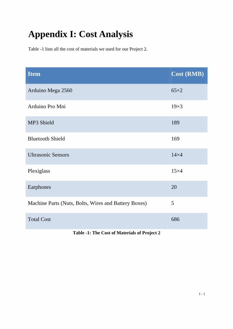
I - 1
Appendix I: Cost Analysis Table -1 lists all the cost of materials we used for our Project 2.
Item Cost (RMB)
Arduino Mega 2560 65×2
Arduino Pro Mni 19×3
MP3 Shield 189
Bluetooth Shield 169
Ultrasonic Sensors 14×4
Plexiglass 15×4
Earphones 20
Machine Parts (Nuts, Bolts, Wires and Battery Boxes) 5
Total Cost 686
Table -1: The Cost of Materials of Project 2

I - 2
Table -2 lists all the cost of materials we used for our final prototype.
Item Cost (RMB)
Arduino Mega 2560 65
Arduino Pro Mni 19
MP3 Shield 189
Ultrasonic Sensors 14×2
Plexiglass 15
Earphones 20
Machine Parts (Nuts, Bolts, Wires and Battery Boxes) 5
Total Cost 341
Table -2: The Cost of Materials of Final Prototype
Actually, the total cost for our final design might be less if it can be put into assembly line. The Arduino boards have so many functions, which are beyond our demand, that increase their prices. If we developed a board that only met our requirement, the total cost would decrease a lot.