virtual network based on sdn and iot
TRANSCRIPT

The Faculty of Electrical Engineering The University of Melbourne
Virtual Networks Based on SDN and IoT
Student: Chien-Cheng Lai
Student ID: 665452
Supervisor: Dr Jayavardhana Gubbi
Dr Marimuthu Palaniswami

ELEN90011 Directed Studies
1
Table of Contents Executive Summary .......................................................................................... 6
1. Introduction ................................................................................................. 8
2. Network Virtualization ................................................................................. 9 2.1. Types of virtualization .................................................................................... 10 2.2. Virtualization Tools ........................................................................................ 11
2.2.1. Xen .......................................................................................................... 11 2.2.2. VMware ................................................................................................... 12 2.2.3. OpenVZ ................................................................................................... 12
2.3. Performance Evaluation ................................................................................ 13
3. Virtual Network Interface .......................................................................... 15 3.1. Network virtualization approaches ................................................................. 15 3.2. Network virtualization Technology ................................................................. 18 3.3. Xen prototype ................................................................................................ 22 3.4. OpenFlow prototype ...................................................................................... 24
4. Performance Improvement and Control of Virtual Network Elements ...... 27 4.1. Improvement on Xen prototype ..................................................................... 28
4.1.1. Xen migration .......................................................................................... 28 4.1.2. I/O virtualization techniques .................................................................... 29
4.2. Improvement on OpenFlow prototype ........................................................... 30 4.2.1. OpenFlow migration ................................................................................ 31 4.2.2. OpenFlow discovery ................................................................................ 32 4.2.3. OpenFlow spanning tree ......................................................................... 32
5. Autonomic Systems in Context-Aware Technologies ............................... 34
5.1. Architecture and operation of autonomic systems ........................................ 34 5.2. Piloting with multi-agent systems .................................................................. 35 5.3. Content-aware technology for network control .............................................. 38
6. Providing Isolation and Quality of Service to Virtual Networks ................. 40 6.1. Difficulty in packet forwarding using Xen ....................................................... 40 6.2. Maximum Usage Controller ........................................................................... 42
7. Piloting System ......................................................................................... 45 7.1. Autonomic Piloting Systems .......................................................................... 45 7.2. The multi-agent APS ..................................................................................... 48
ELEN90011 Directed Studies
2
8. Management and Control: The Situated View .......................................... 53 8.1. The fuzzy control system ............................................................................... 53 8.2. Anomaly Detection for Autonomous Management Virtual Networks System
(ADAGA) ................................................................................................................. 54
9. Internet of things (IoT) .............................................................................. 56
10. Software Defined-Network on Virtual Network and IoT .......................... 57 10.1. The Network Operating System .................................................................. 58 10.2. The SDN interface ....................................................................................... 58 10.3. Network virtualization on SDN ..................................................................... 59 10.4. Internet of Things (IoT) on SDN .................................................................. 60
11. Conclusion .............................................................................................. 62
12. References ............................................................................................. 63

ELEN90011 Directed Studies
3
Figure list Figure 2.1 Non-virtual vs virtual computational environment [1] ....................... 9
Figure 2.2 Pluralistic architecture of virtual networks [1] ................................. 10
Figure 2.3 Full Virtualization [2] ....................................................................... 11
Figure 2.4 Paravirtualization [2] ....................................................................... 11
Figure 3.1. Network Architecture: Monist and Pluralist modes [5] .................. 15
Figure 3.2 Types of Virtualization Interface [6] ................................................ 16
Figure 3.3 Network Virtualization Models [7] ................................................... 17
Figure 3.4 Xen virtual networking: one data and control planes per virtual
router [9] ................................................................................................... 18
Figure 3.5 OpenFlow virtual networking: a shared data plane per node with all
the control planes [9] ................................................................................ 19
Figure 3.6 Header fields in an OpenFlow Network [1] ..................................... 19
Figure 3.7 The centralized OpenFlow controller model [1] .............................. 20
Figure 3.8 Forwarding table in TCP/IP and OpenFlow based networks [9] .... 21
Figure 3.9 Network relocation using Xen and OpenFlow [1] ........................... 22
Figure 3.10 Xen prototype architecture [10] .................................................... 23
Figure 3.11 Controller, physical and virtual router module interactions [10] ... 24
Figure 3.12 OpenFlow prototype architecture [7] ............................................ 25
Figure 3.13 Application layer in OpenFlow GUI [7] ......................................... 26
Figure 4.1 Relationship between piloting plane and virtualized network element
[11] ........................................................................................................... 27
Figure 4.2 The architecture of virtual network elements [11] .......................... 28
Figure 4.3 Router migration between virtual and physical nodes [10] ............ 29
Figure 4.4 The FlowVisor operation [12] ......................................................... 30
Figure 4.5 The hierarchy of FlowVisor [12] ..................................................... 31
Figure 4.6 The operation of Flow Migration [13] .............................................. 32
Figure 4.7 LLDP frame format [14] .................................................................. 32
Figure 4.8 Network Topology by using spanning tree algorithm [1] ................ 33
Figure 5.1 The architecture of an autonomic element [16] .............................. 34
Figure 5.2 Autonomic control loop [1] .............................................................. 35
Figure 5.3 A multi-agent system architecture [17] ........................................... 36
Figure 5.4 Ginkgo architecture [15] ................................................................. 36

ELEN90011 Directed Studies
4
Figure 5.5 Dimax architecture [15] .................................................................. 37
Figure 5.6 JADE architecture [18] ................................................................... 38
Figure 6.1 Xen Architecture with two virtual networks [1] ................................ 40
Figure 6.2 Packet forwarding in Xen-based networks [22] .............................. 41
Figure 6.3 Availability of the secure data plane update via using MUC [1] ..... 43
Figure 6.4 Influence of MUC over the RTT [22] .............................................. 43
Figure 6.5 Resource sharing control by using MUC and TC [21] .................... 44
Figure 7.1 An autonomic piloting-oriented architecture [25] ............................ 46
Figure 7.2 Architecture of autonomic piloting system [1] ................................ 47
Figure 7.3 Different situated views based on the definition of algorithm [1] .... 47
Figure 7.4 The piloting system in three autonomic planes [27] ....................... 48
Figure 7.5 Class diagram of the PAs information model [28] .......................... 49
Figure 7.6 The multi-agent system for self-management of VNs [29] ............. 50
Figure 7.7 Recovery time with the multi-agent system and SCP [25] ............. 51
Figure 7.8 The Cloud environment with the multi-agent system of the VN [28]
................................................................................................................. 52
Figure 8.1 The Fuzzy control system architecture [6] ..................................... 54
Figure 8.2 The Processor utilization of a virtual router with and w/o controller
[31] ........................................................................................................... 54
Figure 8.3 Network components in an ADAGA system [31] ............................ 55
Figure 10.1 Traditional and Software-Defined Network architectures [34] ...... 57
Figure 10.2 The NOS Architecture [37] ........................................................... 58
Figure 10.3 The SDN Interface [38] ................................................................ 59
Figure 10.4 Typical IoT gateways for smart homes [40] ................................. 61
Figure 10.5 SDN enabled IoT gateways for smart homes [40] ....................... 61

ELEN90011 Directed Studies
5
Table List Table 2.1 Performance Evaluation of Virtualization Tools [1] ......................... 13
Table 5.1 An architecture of context-aware systems [15] ............................... 39
Table 6.1 CPU consumption on dom0 [21] ..................................................... 41
Table 7.1 The architecture of Virtual Network environment [25] ..................... 45
Table 7.2 The main functions of Autonomic Piloting Systems [26] ................. 46

ELEN90011 Directed Studies
6
Executive Summary The network has led us into the digital society with information exchange
instantly around the world. However, with the growth complexity of the
traditional network, it becomes difficult to manage based on close or
proprietary network architectures and provide customized services to the
subscribers. To deal with the limitation for physical networks, virtual networks
are proposed depending on a pluralist network architecture, enabling multiple
virtual networks to coexist on a shared virtualization layer for a dynamic multi-
stack network.
A virtual network divides slicing of a physical resource into several virtual
resources including of a set of virtual routers and links on the same physical
infrastructure to enhance network performance. Xen and OpenFlow are
introduced for network virtualization, allowing multiplex several virtual networks
without performance loss.
In the traditional network model, a router comprises a control plane and data
plane. The control plane decides how to cope with network traffic and data
plane forwards traffic depending on the decisions made by the control plane.
The Xen architecture enables several Virtual Machines (VMs) to execute
simultaneously on the same hardware. Each VM runs a virtual router with its
own control and data planes that can be virtualized to provide influential and
flexible platform for network control and management. Moreover, It allows
adding new functions such as hop-by-hop packet processing, which can
implement network authentication and access control.
On the other hand, OpenFlow is an open standard architecture that allows
providing open protocols, and programing the flow table in different switches
and routers by centralizing control planes in a controller and separate the data
planes in the routers. Therefore, OpenFlow can easily maintain the whole
topology over all the virtual nodes.

ELEN90011 Directed Studies
7
The OpenFlow architecture is based on Software-defined network (SDN),
which can provide the following benefits:
• Dynamic and adaptive management
• Low cost
• Centralization and optimization
• Load-balancing and scalability
• Fault tolerance
SDN allows the network administrator to manage and program resources
according to user requirement via available Application Programming
Interfaces (APIs), which are proprietary or open on a controller. By using the
SDN data-control separation, it allows establishing slices based on multiple
parameters such as bandwidth, flowspace and CPU loads. Each slice is
independent without interference of other slices and subdividing slices can
establish the hierarchical model to improve the performance of SDN virtual
networks.
Furthermore, The SDN can modify the network behavior according to user
needs and provides flexible network management on Internet of things (IoT).
With an OpenFlow-based virtual network, it enables the Internet access control,
user management and monitoring according to usage capacity for each user or
device.
In the smart home, the IoT acts as a gateway to connect each of smart sensor-
embedded devices and forward data to external networks. If there are
thousands of hundreds IoT gateways in the smart home networking, they will
become very difficult to manage with high costs for organizations when the
network policy changes or the requirement of updating the software. By using
SDN, IoT gateways are regarded as the SDN-enabled switches and
programmed by the controller for routing, access control, and secure tunnel
establishment between the IoT gateway and data centers. Therefore, the SDN
controller can effectively centralize management of each IoT gateway for the
implementation of smart homes.

ELEN90011 Directed Studies
8
1. Introduction With the advanced technology of the Internet, the network facilitates the
information exchange around the world. Nevertheless, the traditional network
becomes too complicated to manage because of closed and proprietary
network architectures. It is difficult to establish new and innovative services on
a single data center or interconnected data centers for enterprises. The main
cause of a traditional network limitation is that using switches, router and other
network devices to implement the large number of distributed protocols
becomes too complex on closed and proprietary interfaces. This has led to
four major issues.
Difficulty of optimization is the first issue. It is difficult for network operators to
introduce new revenue services and optimize the costly infrastructures such as
data center, wide area networks and enterprise networks. Known issues like
security, mobility, robustness and manageability of traditional networks are the
second problem that have not been successfully dealt with so far. Capital costs
are another problem. Operating costs continuous growth but the return of
investment has not been compensating yet. Difficulty of customization is a
further issue. Network operators and third parties are able to provide
customized cost effective solutions to subscribers because of proprietary and
closed networks.
In order to cope with the current limitations and support new requirements,
network virtualization is proposed based on a pluralist network architecture,
allowing multiple virtual networks to coexist on the top of a shared virtualization
layer for a dynamic multi-stack network. By doing so, service providers have
more opportunities to provide real-time multiple end-to-end and customized
services to customers with security levels.

ELEN90011 Directed Studies
9
2. Network Virtualization Virtualization is a technique for sharing computational resources from physical
hardware, allowing levels of isolation between virtual environments. The
difference between a non-virtualized and virtualized computational
environment is shown in Figure 2.1. The left side of the figure is a conventional
computational architecture that an Operating System (OS) controls the bottom
hardware and applications are run on the OS. On the contrary, a virtualized
computational environment offers a virtualization layer, which enables multiple
OSs to execute simultaneously. Each OS has its own applications and controls
their access to the hardware [1].
Figure 2.1 Non-virtual vs virtual computational environment [1]
The benefit of virtualization can centralize storage pools by using virtual
volumes to consolidate free capacity and also integrate management interface
in order to reduce complexity and enhance system effectiveness.
Furthermore, virtualization technique can provide multiple virtual networks that
are comprised of a set of virtual routers and links [2]. Each virtual network has
a particular network stack to share a single physical network infrastructure, as
shown in Figure 2.2.
Virtual router resources include Central Processing Unit (CPU), Random
Access Memory (RAM), storage devices and network. CPU is used for
incoming packets processing. RAM is utilized to store forwarding the tables,
which is comprised of packets [3]. The main use of storage device is to store
Virtual Machine (VM) images. Network conducts forward packets as a task of a
router.

ELEN90011 Directed Studies
10
Figure 2.2 Pluralistic architecture of virtual networks [1]
Virtualization is implemented by a hypervisor or Virtual Machine Monitor (VMM)
that multitask the computational resources between multiple virtual
environments or known as VMs [1].
In order to establish a hypervisor for hardware virtualization, there are three
requirements: efficiency, resource control and equivalency. First of all, the
instructions of virtual CPU (vCPU) should be effectively running in the real
CPU without intervention from the hypervisor. Secondly, the hypervisor can
control all of the resources [2]. Finally, a virtual interface can provide to virtual
environment equivalent to the original interface.
2.1. Types of virtualization CPU virtualization includes full virtualization and para-virtualization. Full
virtualization virtualizes the original interface that is exposed to virtual
environment and the guest OS located in the VM shown in figure 2.3.
Therefore, the guest OS can execute directly without modifications [2].

ELEN90011 Directed Studies
11
Figure 2.3 Full Virtualization [2]
Para-virtualization means alongside virtualization that communicate between
the guest OS and the hypervisor to provide better performance and efficiency
shown in Figure 2.4. However, the guest OS has to be modified and
recompiled to produce para-virtualized OS images.
Figure 2.4 Paravirtualization [2]
2.2. Virtualization Tools There are three virtualization tools: Xen, VMware and OpenVZ.
2.2.1. Xen Xen is an open-source hypervisor that uses the para-virtualization technique
and runs multiple VMs simultaneously on a single physical machine. Xen
architecture consists of a hypervisor resided above the physical hardware and
VMs located over a hypervisor. Each VM can run its own OS and applications
as shown in Figure 2.5 [4].

ELEN90011 Directed Studies
12
Figure 2.5 The Xen architechture [4]
2.2.2. VMware VMware is based on the full virtualization and the architecture is comprised of
the hardware interface, VMM, resource manager, service console and VM
shown in Figure 2.6. VMware can dynamically share sources that can allocate
and relocate by the system administrator [3].
Figure 2.6 VMware architecture [3]
2.2.3. OpenVZ OpenVZ is an open source OS-Level virtualization tool shown in Figure 2.7. A
Virtual Private Server (VPS) isolates each virtual environment and looks like a
physical layer with its own process, files, Internet Protocols (IP) addresses,
system configuration and permission of root shell access[1]. Hence, each VPS

ELEN90011 Directed Studies
13
can have its own applications and services independent of each other.
Nevertheless, due to the limitation of the same Linux OS on OpenVZ, it
becomes less flexible compared to Xen and VMware.
Figure 2.7 OpenVZ architecture [1]
2.3. Performance Evaluation In order to distinguish the performance among three virtualization tools, the
same specification hardware was adopted to test CPU, Memory, Hard disk, file
system performance and network performances via algorithms and
benchmarking tools. The result was shown as Table 2.1.
Performance Xen VMware OpenVZ
CUP Good Poor Fair
Memory Fair Poor Good
Hard Disk Fair Poor Good
File System Poor Fair Good
Network Excellent Poor Fair Table 2.1 Performance Evaluation of Virtualization Tools [1]
In general, Xen not only outperformed among CPU, memory and virtualized
network but also shares the same computer resources between the VMs with
no attenuation of performance caused by the hypervisor. On the other hand,
VMware performed the worst result in the test and does not allow modification
of source codes that become more inflexible. Similarly, although OpenVZ had
great computational performance, it is limited to the same OS and kernel that

ELEN90011 Directed Studies
14
result in different levels of router complexity [1]. As a result, and Xen becomes
the best ideal virtualization tool for building virtual routers that support any OS
inside the VMs.
ELEN90011 Directed Studies
15
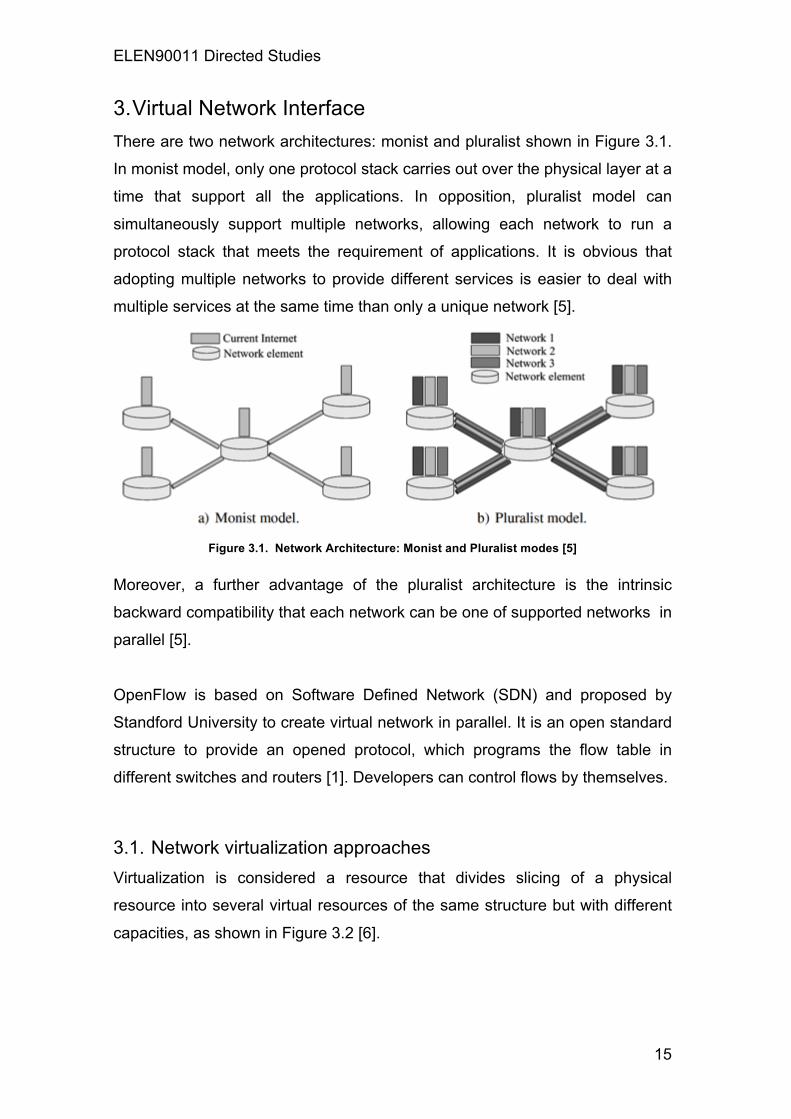
3. Virtual Network Interface There are two network architectures: monist and pluralist shown in Figure 3.1.
In monist model, only one protocol stack carries out over the physical layer at a
time that support all the applications. In opposition, pluralist model can
simultaneously support multiple networks, allowing each network to run a
protocol stack that meets the requirement of applications. It is obvious that
adopting multiple networks to provide different services is easier to deal with
multiple services at the same time than only a unique network [5].
Figure 3.1. Network Architecture: Monist and Pluralist modes [5]
Moreover, a further advantage of the pluralist architecture is the intrinsic
backward compatibility that each network can be one of supported networks in
parallel [5].
OpenFlow is based on Software Defined Network (SDN) and proposed by
Standford University to create virtual network in parallel. It is an open standard
structure to provide an opened protocol, which programs the flow table in
different switches and routers [1]. Developers can control flows by themselves.
3.1. Network virtualization approaches Virtualization is considered a resource that divides slicing of a physical
resource into several virtual resources of the same structure but with different
capacities, as shown in Figure 3.2 [6].

ELEN90011 Directed Studies
16
Figure 3.2 Types of Virtualization Interface [6]
The concurrent exist of several virtual slices over the same resource is critical
because the virtualization layer separates the real resource and slices. Figure
3.2 also illustrates computer virtualization and network virtualization. The
computer virtualization is run by the Virtual Machine Monitor (VMM), which
supplies VMs with a virtual interface similar to hardware devices such as a
processor, memory, Input and Output (IO) devices. Likewise, each VMs can
implement directly over the physical hardware, but actually the resource of
hardware is shared among several VMs [7]. This is also called resource
sharing slicing that each VM is isolated and cannot interfere with each other.
Furthermore, computer virtualization is widely used in data centers to conduct
multiple servers in a single physical device.
The network virtualization originated from Virtual Private Networks (VPNs) and
Virtual Local Area Networks (VLANs) [8], allowing router virtualization by a
customized network protocol stack. Furthermore, the network virtualization can
be illustrated in the virtualization layer of architectural design shown in Figure
3.3.

ELEN90011 Directed Studies
17
Figure 3.3 Network Virtualization Models [7]
Figure 3.3 a) shows the traditional network element model with a single control
and data plane. In a router, the control plane is in charge of execution of the
network control such as routing protocols while the data plane is responsible
for implementing forwarding tables and hardware data routes.
In Figure 3.3 b), the control plane is virtualized on the virtualization layer,
allowing multiple control software to run on it and sharing the same data plane.
This model allows implementing multiple and customized protocol stacks
rather than single one protocol stack that greatly enhance programmability. In
Figure 3.3 c), both control and data planes are virtualized, enabling
customization data plane by sacrificing the performance of packet forwarding.
For example, each virtual control plane may not completely isolate and
interfere with each other in Figure 3.3 c) that results in dropping packets during
storing forwarding tables [7]. This will become a trade-off between network
programmability and performance.

ELEN90011 Directed Studies
18
3.2. Network virtualization Technology By implementing shared data planes, Xen and OpenFlow can be used for
network virtualization, enabling multiplex several virtual networks without
performance loss compared to the same packet rate handled by a single virtual
network.
Xen enables several VMs to execute simultaneously on the same hardware as
shown in Figure 3.4. Each VM runs a virtual router with its own control and
data planes in the Xen virtualization layer [9]. Both data and control planes can
be virtualized to provide influential and flexible platform for network control and
management. It allows adding new functions such as hop-by-hop packet
processing, which can be used for network authentication and access control.
Figure 3.4 Xen virtual networking: one data and control planes per virtual router [9]
On the other hand, OpenFlow can separate control and data planes in order to
carry out the packet forwarding procedure in the data plane and the network
control procedure in the control plane. A controller includes a shared data
plane which is used for flow table while all the control planes are centralized in
a node, enabling running applications under the control of virtual network
shown in Figure 3.5 [9].

ELEN90011 Directed Studies
19
Figure 3.5 OpenFlow virtual networking: a shared data plane per node with all the control planes [9]
The data plane in OpenFlow is a flow table described by counters, header
fields and actions. The header fields are a 12-tuple model that describes the
packet header shown in Figure 3.6. The 12-tuple structure supports high
flexibility for packet forwarding because a flow not only can be in Transmission
Control Protocol (TCP/IP) network, but also on the TCP port for the Medium
Access Control (MAC) address. For the objective in the future, packet header
will be described by virtual network administrators for a combination of fields
instead of fixed fields. By doing so, OpenFlow can forward packets by running
any protocol stack in networks.
Figure 3.6 Header fields in an OpenFlow Network [1]
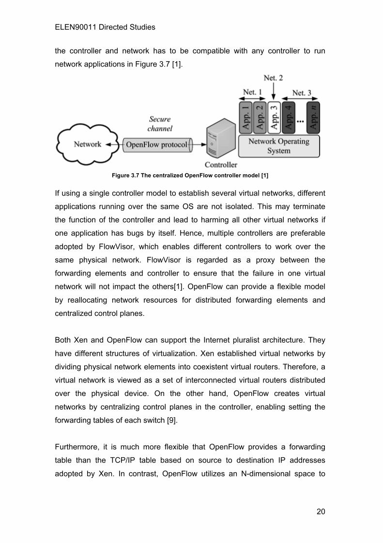
The controller in OpenFlow works as an interface between the network
applications and forwarding elements that supplies the basic functions to
obtain packets from a flow to monitor nodes. An OpenFlow protocol between
ELEN90011 Directed Studies
20
the controller and network has to be compatible with any controller to run
network applications in Figure 3.7 [1].
Figure 3.7 The centralized OpenFlow controller model [1]
If using a single controller model to establish several virtual networks, different
applications running over the same OS are not isolated. This may terminate
the function of the controller and lead to harming all other virtual networks if
one application has bugs by itself. Hence, multiple controllers are preferable
adopted by FlowVisor, which enables different controllers to work over the
same physical network. FlowVisor is regarded as a proxy between the
forwarding elements and controller to ensure that the failure in one virtual
network will not impact the others[1]. OpenFlow can provide a flexible model
by reallocating network resources for distributed forwarding elements and
centralized control planes.
Both Xen and OpenFlow can support the Internet pluralist architecture. They
have different structures of virtualization. Xen established virtual networks by
dividing physical network elements into coexistent virtual routers. Therefore, a
virtual network is viewed as a set of interconnected virtual routers distributed
over the physical device. On the other hand, OpenFlow creates virtual
networks by centralizing control planes in the controller, enabling setting the
forwarding tables of each switch [9].
Furthermore, it is much more flexible that OpenFlow provides a forwarding
table than the TCP/IP table based on source to destination IP addresses
adopted by Xen. In contrast, OpenFlow utilizes an N-dimensional space to

ELEN90011 Directed Studies
21
define each flow, where N is the number of header fields for specifing a flow [9],
as shown in Figure 3.8.
Figure 3.8 Forwarding table in TCP/IP and OpenFlow based networks [9]
By using N-dimensional space in the forwarding table, it enables packets to be
forwarded not only on the IP but also other protocols. Consequently, OpenFlow
can support more virtual networks running in parallel while Xen is limited to the
number of VMs that can be multiplexed over the network hardware.
In order to maintain the same virtual topology in the Xen virtual network,
migrating virtual routers are used to transfer a physical router and establish
tunnels from neighborhood. On the other hand, OpenFlow, is simpler for
network reallocation because of the centralized control plane, which maintains
the whole topology over all the nodes, identifying where the physical devices
are and how they connect [1], as shown in Figure 3.9.

ELEN90011 Directed Studies
22
Figure 3.9 Network relocation using Xen and OpenFlow [1]
3.3. Xen prototype Xen prototype is based on Web services that contain two main sections: the
Virtual Machine Server (VMS) and piloting plane as shown in Figure 3.10. The
piloting plane is for the management of virtual network elements by sending
commands to the VMS and provides services for integrated interface to control
network Xen machines. However, the piloting plane can be replaced by a
Graphic User Interface (GUI), which can access to whole network
administrative tasks by the Web service communication interface [10].

ELEN90011 Directed Studies
23
Figure 3.10 Xen prototype architecture [10]
On the other hand, there are other modules that have to be developed for
critical tasks in the VMS. For example, in order to obtain information related to
CPU, memory and network-related data, a data gatherer module is needed. In
the same way, the topology discovery module is also required to obtain the
virtual and physical network topologies. Migration module is needed for
migration of virtual routers without packet losses as well as control the virtual
router throughput. A further module is a scheduler for Virtual CPUs of the
virtual routers. These modules are required to retrieve data from virtual,
physical routers and the controller. Consequently, communication module is
needed to interconnect all of them shown in Figure 3.11. There is another
client communication module establishing exchange Extensible Markup
Language (XML) messages with the request and then delivering it via a socket
to the server communication module executing inside the physical router [10].
If the request comes from the virtual router, then the physical layer acts as an
intermediate between the virtual router and controller.
All in all, VMS is used to address physical and virtual hosts of the network
while the GUI simplifies the network administration by the Web service
communication interface.

ELEN90011 Directed Studies
24
Figure 3.11 Controller, physical and virtual router module interactions [10]
3.4. OpenFlow prototype The OpenFlow prototype is based on Web Services. The communication
between the prototype and external applications utilizes the HTTP (Hyper Text
Transfer Protocol) to exchange XML messages. In Figure 3.12, the Network
Operating System (NOS) controller offers the OpenFlow protocols and
implements the secure channel for running the applications. There are six
applications running on a NOS controller: Stats application is used to collect
switch-related statistics and convert them into XML messages. Discovery
application explores the network topology and describes it as an XML
message. Spanning Tree application implements a spanning tree algorithm to
avoid network loops and redundant broadcast retransmissions. Flow Manager
application carries out flow changes by adding, deleting and modifying flows.
Flow Migration application conducts flow modifications by migrating a flow from
one path to another [7]. Web Server application undertakes the HTTP protocol
to provide an interface between NOS controller and the external application.

ELEN90011 Directed Studies
25
Figure 3.12 OpenFlow prototype architecture [7]
Moreover, users can access the interface, execute commands and queries,
and modify flow tables to facilitate configuration and network management via
a Web browser.
The OpenFlow GUI is comprised for three layers shown in Figure 3.13. Data
link layer is the first layer, which is comprised of a NOX controller and its
applications. It is used to conduct user commands and collect data. The
second layer is data processing layer that contains a Web server for
processing all received information before sending to other layers. The
presentation layer is the third layer that consists of script files and mark
described by the web browser such as Hyper Text Markup Language (HTML).
It organizes and displays the data to the user. Furthermore, the application
communicates among these layers over the HTTP protocol [7].

ELEN90011 Directed Studies
26
Figure 3.13 Application layer in OpenFlow GUI [7]

ELEN90011 Directed Studies
27
4. Performance Improvement and Control of Virtual
Network Elements Piloting plane is developed to execute intelligent algorithms to automatically
instantiate, delete virtual network, migrate network elements and set resources
allocation of parameters as shown in Figure 4.1. Therefore, piloting plane can
dynamically allocate resources to each virtual network based on the condition
of current network, number of users, priority of per virtual network and Service
Level Agreements (SLA) [11].
Figure 4.1 Relationship between piloting plane and virtualized network element [11]
A virtual network element consists of the virtualization and piloting planes. The
virtualization plane offers the platform for running logical network elements
over a single shared physical network. The piloting plane supports the
intelligence performance of network optimization based on SLAs for each
virtual network.
In Figure 4.2, the controller is regarded as the piloting plane that aggregates
and receives information sent by nodes. All nodes are required to provide an
interface with piloting plane and convert to XML control message [11]. Sensors
and actuators also form the virtualization system. Sensors collect information
and actuators implement actions.

ELEN90011 Directed Studies
28
Figure 4.2 The architecture of virtual network elements [11]
4.1. Improvement on Xen prototype The Xen-based prototype consists of controller, router and client nodes. The
controller node is used to receive and consolidate data from all network nodes.
It obtains data and sends commands to physical and virtual router. Router
nodes include physical and virtual routers that execute several modules and
receive commands from the controller node. Finally, the client node enables
users to interact with the controller by using the GUI for user monitoring and a
simple control interface shown in Figure 3.11.
The controller node involves the VMS and client communication. The VMS
uses a Simple Object Access Protocol (SOAP) interface to interact with the
piloting plane and client node. It integrates all prototype information and runs
algorithms. The client communication communicates with other router nodes
running on other routers [10]. In addition, if a request is addressed to a virtual
router, the proxy module in the physical router is forwarded to the virtual router
as a message channel.
4.1.1. Xen migration The purpose of Xen migration is to organize virtual networks or routers among
physical resources with influencing the packet forwarding and network control
service. Xen migration also can reconfigure dynamically of the network
topologies without turning off the running routers.
In Figure 4.3, the virtual node B is migrated from the physical node 2 to node 6.
Nevertheless, there is no one-hop neighbor of the physical node 1. Hence, a

ELEN90011 Directed Studies
29
tunnel from the physical node 6 to node 1 requires to be established to
simulate a one-hop neighborhood in order to conduct link migration. Another
solution is to build a new virtual router to replace the tunnel [10].
Figure 4.3 Router migration between virtual and physical nodes [10]
4.1.2. I/O virtualization techniques I/O virtualization is undertaken by the VMM, which is required to multiplex
outgoing data flows and de-multiplex incoming data flows. I/O virtualization
techniques are comprised of direct assignment of device, multi-queued devices
and Single Root I/O Virtualization (SR-IOV). The direct assignment of device
uses Direct Memory Access (DMA) to transfer data directly to a VM without
being processed by VMM or hypervisor.
Multiple queues are address by the Interface Card (NIC) in order to classify
packets using a certain pattern such as the virtual local area network (VLAN)
or MAC destination address and push them into the appropriate queue.
Consequently, each queue has its own traffic isolated from each other.

ELEN90011 Directed Studies
30
The SR-IOV standard can share Peripheral Component Interconnect Express
(PCI-Express) devices such as NICs access among VMs [12]. It also can
bypass the VMM involvement in data transfer.
4.2. Improvement on OpenFlow prototype The FlowVisor is adopted to allow multiple NOS controllers to execute in
parallel in order to divide the physical network into several virtual networks. It
regulates the sharing of network resources such as the bandwidth, traffic,
usage of switch CPU and flow tables [1].
The FlowVisor is regarded as a special type of OpenFlow controller. In Figure
4.4, the FlowVisor intercepts the flow messages delivered by guest controller
that verifies the user slicing policy. Then it modifies the message to refine the
control to a slice of the network [12]. Finally, if the message matches the slice
policy, FlowVisor forwards it from switches to guests.
Figure 4.4 The FlowVisor operation [12]

ELEN90011 Directed Studies
31
The FlowVisor hierarchy virtualizes several switches in parallel. In Figure 4.5
FlowVisor 1 recursively divides the virtual slices defined by FlowVisor 2 and 3.
The OpenVisor aims at five network resources: bandwidth isolation, topology
exploration, traffic, device CPU surveillance and control of forwarding tables.
Figure 4.5 The hierarchy of FlowVisor [12]
4.2.1. OpenFlow migration Flow Migration defines a new route between source and destination of
OpenFlow switches, and then modifies the current path of the flow to new path
without packet loss. Dijkstra Algorithm is utilized to calculate the smallest path
from the source to the destination for the Flow migration shown in Figure 4.6 in
order to minimize the number of hops in the new path [13].

ELEN90011 Directed Studies
32
Figure 4.6 The operation of Flow Migration [13]
4.2.2. OpenFlow discovery The discovery application carries out the Link Layer Discovery Protocol (LLDP),
which enables nodes to send information of capabilities and the current status
of network devices. The LLDP frame format is shown in Figure 4.7. With this
information, the application establishes a data structure, which involves the
source switch and port, and destination switch and port. Therefore, the data
structure is used to identify a link and the aggregation of all links in a network
describes the network topology [14].
Figure 4.7 LLDP frame format [14]
Moreover, the default application only provides the physical network topology,
but information about the prototype of virtual networks also required. Therefore,
the modified discovery application is adopted to obtain the definition and
forward traffic in virtual networks.
4.2.3. OpenFlow spanning tree Multiple paths between a source and destination are a common characteristic
of network topologies. However, although these redundant paths raise network
reliability, it can also lead to errors during broadcast in Ethernet networks. As a

ELEN90011 Directed Studies
33
result, the spanning tree algorithm is used to establish a topology for
broadcasting frames without creating loops as shown in Figure 4.8 [1].
Figure 4.8 Network Topology by using spanning tree algorithm [1]

ELEN90011 Directed Studies
34
5. Autonomic Systems in Context-Aware Technologies Autonomic systems such as multi-agent systems (MASs) are used for a pilot
system to adapt complex environment, conduct the autonomic computing of
highly dynamic networks without intervention and increase network scalability
[15].
5.1. Architecture and operation of autonomic systems The architecture of an autonomic element is composed of a managed
component and correspondent autonomic manager. An autonomic manager
undertakes the requirement of self-monitoring and self-adjusting. An automatic
manager includes an internal monitor, external monitor, self-monitor, self-
adjuster and heartbeat monitor as shown in Figure 5.1.
Figure 5.1 The architecture of an autonomic element [16]
An internal monitor looks up the state of the managed component and sends
the information to the self-monitor for action and assessment. Likewise, an
external monitor examines the state of the environment through an autonomic
signal channel, which connects to the other autonomic managers and passes
the information to the self-monitor component. A self-adjuster enables the
status adjustment of the managed component. A heartbeat monitor
summarizes the state of autonomic element and sends to other autonomic
elements for the control of the autonomic state [16].
ELEN90011 Directed Studies
35
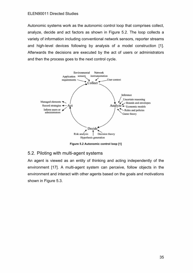
Autonomic systems work as the autonomic control loop that comprises collect,
analyze, decide and act factors as shown in Figure 5.2. The loop collects a
variety of information including conventional network sensors, reporter streams
and high-level devices following by analysis of a model construction [1].
Afterwards the decisions are executed by the act of users or administrators
and then the process goes to the next control cycle.
Figure 5.2 Autonomic control loop [1]
5.2. Piloting with multi-agent systems An agent is viewed as an entity of thinking and acting independently of the
environment [17]. A multi-agent system can perceive, follow objects in the
environment and interact with other agents based on the goals and motivations
shown in Figure 5.3.

ELEN90011 Directed Studies
36
Figure 5.3 A multi-agent system architecture [17]
In order to establish context-aware infrastructure, an autonomic platform
including a knowledge plane and piloting plane has need to be created. There
are three types of autonomic platforms: the Ginkgo, Dimax and Java Agent
Development Framework (JADE) platforms [15].
The Ginkgo platform provides the knowledge plane with application information
and distributed knowledge in real time shown in Figure 5.4.
Figure 5.4 Ginkgo architecture [15]
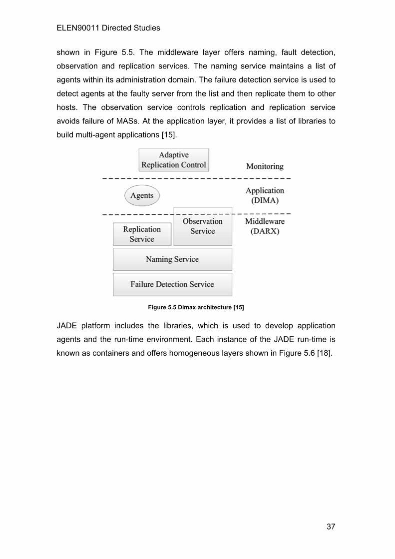
Dimax is a fault-tolerant multi-agent platform that provides multiple services. It
can divide into three levels: the middleware, application and monitor layers
ELEN90011 Directed Studies
37
shown in Figure 5.5. The middleware layer offers naming, fault detection,
observation and replication services. The naming service maintains a list of
agents within its administration domain. The failure detection service is used to
detect agents at the faulty server from the list and then replicate them to other
hosts. The observation service controls replication and replication service
avoids failure of MASs. At the application layer, it provides a list of libraries to
build multi-agent applications [15].
Figure 5.5 Dimax architecture [15]
JADE platform includes the libraries, which is used to develop application
agents and the run-time environment. Each instance of the JADE run-time is
known as containers and offers homogeneous layers shown in Figure 5.6 [18].

ELEN90011 Directed Studies
38
Figure 5.6 JADE architecture [18]
5.3. Content-aware technology for network control A context-aware system can be used to characterize the situation of an entity
by any information. It also enables the system and network control to work
automatically without human intervention [19].
The context-aware system consists of three functions of subsystems: sensing,
thinking, and acting shown in Figure 5.7. The first sensing subsystem breaks
into sensors and raw data retrieval layers. Sensors are developed to detect
context information from physical and virtual networks. After gathering data by
the raw data retrieval layer, sensors translate raw data into XML data
structures for request by agents. The context information can control the
resource allocation among virtual networks. The computational resources of
network elements include the memory, bandwidth, traffic and network topology.
With the context information, the piloting system can deal with environmental

ELEN90011 Directed Studies
39
changes in order to ensure the isolation and the resource allocation of each
virtual network.
The second thinking subsystem is comprised of preprocessing and
storage/management layers. The preprocessing layer converts and aggregates
all context information from different sensors to offer more accurate information.
The storage/management defines knowledge representation techniques and
store context information in a machine process form.
The third acting subsystem is part of the piloting system responsible for
adapting to environmental changes based on the context information collected
or situations recognized by the sensing or thinking subsystems. The acting
subsystem has four applications: establishment of multiple tailored network,
flexible management, real-time control and monitoring [15].
The establishment of multiple tailored networks can be used in each virtual
network with its own protocol stack, network topology and administration policy.
This can allow service providers to allocate an end-to-end virtual path to
provide customized network services with Quality of Service (QoS) guarantees.
Flexible management in network virtualization layer can move a virtual network
component from one physical hardware to another without the modifying the
virtual network topology. Real-time control supports real-time dynamically
allocation of resources to each virtual network depending on the network
condition, number of users, priority of virtual networks and service level
agreement. Monitoring is a further application for observing available
bandwidth, processor, memory usage, connection and end-to-end delay [19]
Applications Application Subsystem
Storage/Management Thinking Subsystem Preprocessing/Reasoning
Raw Data Retrieval Sensing Subsystem Sensors
Table 5.1 An architecture of context-aware systems [15]

ELEN90011 Directed Studies
40
6. Providing Isolation and Quality of Service to Virtual
Networks A dynamic control, which comprises the local and global control, is proposed to
ensure isolation, Quality of Service (QoS) and improve the Xen network
management and overall performance. The local control can guarantee the
isolation and Service Level Agreement (SLAs) with each physical node in the
Xen network while the global control deals with physical node failures by using
a distributed fault-tolerant algorithm and migrates virtual nodes [20].
6.1. Difficulty in packet forwarding using Xen A virtual network is viewed as a set of virtual routers established over the
physical infrastructure. Xen architecture consists of a hypervisor, a privileged
virtual machine called dom0 and normal virtual machine, called user domains
(domUs) shown in Figure 6.1 [1].
Figure 6.1 Xen Architecture with two virtual networks [1]
The Xen hypervisor manages the access to the physical resource. Dom0 can
directly access the hardware and establish an interface between the virtual
drivers resided in the domUs and physical device. Nevertheless, the Xen
hypervisor cannot effectively isolate dom0 utilization of resources shown in
Table 6.1. A malicious or fault action in domUs can easily consume the dom0
CPU utilization that may lower the overall performance of other domains [21].

ELEN90011 Directed Studies
41
CPU (%) Description
0.71 ± 0.60 Basic CPU consumption on dom0
66.43 ± 8.93 TCP traffic from domU to dom0
85.49 ± 5.91 TCP traffic from domU1 to domU2
1.79 ± 1.01 TCP traffic from an external machine to domU Table 6.1 CPU consumption on dom0 [21]
The traditional Xen architecture is inefficient for running networks because the
packet forwarding of domUs consumes more time and longer path shown in
Figure 6.2a). In opposition, the plane separation can improve the forwarding
performance because data packets are forwarded directly by a shared data
plane in dom0 shown in Figure 6.2b) [22].
Figure 6.2 Packet forwarding in Xen-based networks [22]

ELEN90011 Directed Studies
42
6.2. Maximum Usage Controller In order to provide isolation to the Xen virtualization platform by managing the
use of dom0 resources, the Maximum Usage Controller (MUC) is proposed for
a fixed amount of resources and a parameter known as the weight. The fixed
resource reservation ensures the availability of minimal resources to each
virtual network while the weight aims at idle resources, which allocates among
virtual networks [23].
MUC monitors bandwidth by looking up the volume of bits transmission on
each output physical link. If a router exceeds the distributed bandwidth in the
out link, the MUC punishes a router by dropping its packets. Similarly, the
MUC can manage memory utilization by observing the size of the forwarding
table of per virtual router. If the memory of dom0 reaches the limits, all virtual
routers will occupy more memory. Hence, the fixed resource reservation will be
punished to reduce the size of the routing table [22]. This will reduce
forwarding performance by domUs instead of packet drops.
In addition, a malicious behavior occurs when a domU attempts to break or
damage isolation in virtual networks. It is classified as an opponent domain,
which is also punished by dropping packets or routes. Furthermore, the
punishment should not influence the low-value transmission, but it can avoid a
domU exhausting all dom0 resources.
An effective MUC is analyzed in opponent domains to confirm the efficiency for
sharing resources. The success probability of data plane updates with the
traffic between two virtual machines shown in Figure 6.3 a). The MUC
punishes traffic from domU2 to domU1 to avoid the overload of Dom0
resources [1]. Therefore, MUC guarantees the update of a secure data with
high availability and high-performance connection between routers.

ELEN90011 Directed Studies
43
Figure 6.3 Availability of the secure data plane update via using MUC [1]
In Figure 6.4 a), the round trip time (RTT) is measured the background traffic
with MUC. Without the background traffic, the result shows that data
transmission with a low RTT for both MUC and no MUC. Nevertheless, when
background traffic is implemented, the dom0 CPU is overloaded and
increasing the response time of the system also known as the RTT. On the
other hand, MUC avoids dom0 CPU being overloaded [22]. Although MUC
control leads to packet drops, the drops do not cause a main impact on traffic
shown in Figure 6.4 b).
Figure 6.4 Influence of MUC over the RTT [22]
Another experiment is the average throughput of the TCP and User Datagram
Protocol (UDP) traffic from external virtual machines conducted by the
resource sharing of MUC and traffic control (TC) shown in Figure 6.5. The
available resources are allocated equally between two virtual networks.
Although MUC introduces a more variation in traffic than TC, the average
throughput of MUC has a lower error rate [21]. This result indicates that MUC
has a higher fairness in the link resource sharing for Xen architecture.

ELEN90011 Directed Studies
44
Figure 6.5 Resource sharing control by using MUC and TC [21]

ELEN90011 Directed Studies
45
7. Piloting System The piloting system is used to deal with Virtual Networks (VNs) such as control
and management entities over a multi-agent system. Also, the piloting
architecture is based on piloting agents (PAs) in federations [1].
7.1. Autonomic Piloting Systems Autonomic Piloting Systems (APSs) are proposed by IBM and provide different
management tasks among various nodes, links and services. In order to solve
a problem of conflicting configurations between two sub-networks, the piloting
plane allows collaboration of different autonomic control loops that are non-
conflicting [24].
The architecture of VN environment involves four planes shown in Table 7.1.
The data plane is used to transmit data from a sender to one or multiple
recipients [25]. The management and control planes conduct algorithms for
diagnostics, failure detection, routing, security control and management, and
flow control.
Plane Type Function
Data Plane Forwarding data
Control Plane Control algorithms
Management Plane Features of management
Piloting Plane Provide real-time information to the management and
control plane Table 7.1 The architecture of Virtual Network environment [25]
This architecture can be viewed as autonomic piloting-oriented architecture
illustrated in Figure 7.1. The piloting plane consists of two sub-planes: the
Knowledge Plane (KP) and Orchestration Plane (OP). The KP provides
knowledge for control and management algorithms while the OP synchronizes
networks elements. The main purpose of the Piloting Plane (PP) is to
supervise and integrate all other planes’ behaviors. The PP also can be
regarded as a control framework that can be federated with other PPs,
optimizes monitoring of network and ensure the availability of the required
knowledge [25].

ELEN90011 Directed Studies
46
Figure 7.1 An autonomic piloting-oriented architecture [25]
The PP works as a control workflow for all APSs. Each APS deals with a
cluster of virtual devices or networks by a common policies and knowledge
with the functions in Table 7.2 [26].
Name Functions
Federation Allow the APS or piloting domain to merge into a large
domain
Negotiation The APSs act as the entity and negotiate other
autonomous entities in order to support SLAs
Distribution The APS offers communication and control services that
divides tasks and run simultaneously over multiple PAs
with the PP
Governance Each APS can conduct in an individual, distributed or
cooperative modes
System Views The APS can store and disseminate information via KP
through interfaces Table 7.2 The main functions of Autonomic Piloting Systems [26]
According to Figure 7.2, APSs consist of three types of architecture: The first
type is the dynamic planner, which is used for policy-based dispatcher. It
establishes and eliminates behavior, and conducts the interface for the PAs
and main inter-management functions. The second type implements piloting
tasks and works as a proxy for the communication between APSs and PAs. A

ELEN90011 Directed Studies
47
further type is the situated view, which comprises of the intra-system and inter-
system views. The difference between them is that the intra-system regards a
single APS as an overall view whereas the inter-system views the APSs as a
whole of the entire PP [1].
Figure 7.2 Architecture of autonomic piloting system [1]
Furthermore, situated views may be different depending on the algorithm for
the entire, intermediate and one-hop views illustrated in Figure 7.3.
Figure 7.3 Different situated views based on the definition of algorithm [1]
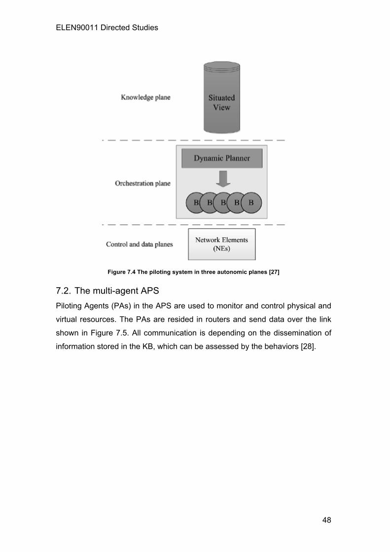
Similarly, an autonomic system is divided into three autonomic planes shown
in Figure 7.4. The OP manages and integrates behaviors in real time via the
dynamic planner. Each behavior is considered as a specialized function
conducted by the agent. In the KP, agents in the network environment review
the situated view for important modifications. In control and data planes,
Network Elements (NEs) are configured such as the condition of computing
bandwidth[27].
ELEN90011 Directed Studies
48
Figure 7.4 The piloting system in three autonomic planes [27]
7.2. The multi-agent APS Piloting Agents (PAs) in the APS are used to monitor and control physical and
virtual resources. The PAs are resided in routers and send data over the link
shown in Figure 7.5. All communication is depending on the dissemination of
information stored in the KB, which can be assessed by the behaviors [28].

ELEN90011 Directed Studies
49
Figure 7.5 Class diagram of the PAs information model [28]
Moreover, the PAs can break into four behaviors: monitor, analyze, plan and
execute, which are conducted periodically in order and creates the autonomic
cycle of the manager. Monitor gathers data from virtual and physical nodes,
and stores in the KB. Analyze diagnoses the usage of physical network link. If
the utilization exceeds the threshold, the KB will update the information to
inform other behaviors. Plan makes a proposal when a threat occurs. Execute
takes an action and inform the modifications for other behaviors [28].
The multi-agent system can be used for a distributed architecture to allow self-
management of VNs over the PP such as self-configuration, self-optimization
and self-protection illustrated in figure 7.6. This distributed management
architecture with self-organizing VNs maintains effective utilization of physical
resources, monitors the target link and minimizes the network traffic load via
the migration of virtual nodes. It is conducted by the self-organization based on
the autonomic control loop [29].

ELEN90011 Directed Studies
50
Figure 7.6 The multi-agent system for self-management of VNs [29]
Furthermore, the multi-agent system is required for failure recovery. Failures
can appear via problems in virtual or physical nodes or even in the physical
links. Hence, agents have a responsibility to diagnose virtual routers and
inform other neighbors for information. Also, an autonomic control loop for self-
healing of VNs is carried out by the dynamic planner and four behaviors of
Monitor, Analyze, Plan and Execute [29].
If the virtual router is failed to connect, it can recover by self-management of
two ways. The first establish a VM from the image file and the second restores
the machine from the backup memory file. The recovery time T! from a VN can
present to the equation:
T! = T! + T! + T! + T!
where T! is failure diagnosed time; T! is the time of planning action which
includes information exchange between agents; T! is the time of creating the
VM and T! is the time of routing protocols.
Similarly, the static and dynamic routings are used for self-management in the
VN. The virtual router is manually configured by the static routing while
dynamic routing conduct the virtual router by the Open Shortest Path First
(OSPF) algorithm [27].

ELEN90011 Directed Studies
51
The multi-agent system with the Secure Copy Protocol (SCP) can also be used
for monitoring the recovery time of the virtual router shown in Figure 7.7. The
dynamic routing consumes more time due to the convergence time the routing
algorithm. Although the approach is time-saving for transmission and storage,
the backup can influence the network performance during the high utilization.
Therefore, distributed storage and increased memory can alleviate the
overhead [25].
Figure 7.7 Recovery time with the multi-agent system and SCP [25]
Finally, the idea of an APS to deal with VNs can also be applied to a cloud
environment shown in Figure 7.8. The PAs monitors network resources and
conducts actions such as power management based on SLA. PAs can be
formed as a group into domains like neighborhoods. A neighborhood
comprises the PAs that can request an action from other neighborhoods such
as the requirement of increasing the bandwidth of the VN [28].

ELEN90011 Directed Studies
52
Figure 7.8 The Cloud environment with the multi-agent system of the VN [28]

ELEN90011 Directed Studies
53
8. Management and Control: The Situated View Control and management of network virtualization allows multiplexing
hardware access and offering logical slice of resource to virtualize networks.
The knowledge plane stocks information of each virtual network elements and
allocates in different nodes, which have a partial view of the knowledge plane.
Therefore, the situated view is a partial view of the whole network subject to
the environment and ambient. The knowledge plane has difficulty in the
schedule of making decisions and updating network element information.
Hence, mechanisms are proposed to detect and correct based on the Xen
platform [1].
8.1. The fuzzy control system The fuzzy control system depends on the detection of SLA violations and the
real-time penalty of misbehaving virtual nodes. It calculates the system load
based on the processor and memory. Furthermore, The fuzzy control system
has small computational complexity and can enhance system performance to
reduce the response time of the controller [6]. The control system architecture
has a distributed management of controller agents, which manage both
physical and virtual routers shown in Figure 8.1.
There are five modules composed the controller agent. The Strategy and
Policy Module (SPM) uses management strategies to control and update the
current strategy for each control and monitoring daemon. The Service Level
Module (SLM) manages the database of each virtual router. The Knowledge
Base Module (KBM) stores information and description of violations, estimates
migration and updates detections. The Actuator Module (AM) obtains the
profile and statistics of each virtual router. The Communication Module (CM)
exchanges information among controllers via secure channels [6].
The fuzzy control system consists of three mechanisms. The profile generation
is the first mechanism to offer utilization statistics and SLA detection of
violation. The system load estimator is another mechanism that combines
multiple resources at the output. The adaptive punishment mechanism is a
further mechanism that produces a level of punishment to the system [30].

ELEN90011 Directed Studies
54
Figure 8.1 The Fuzzy control system architecture [6]
The experiment shows that without the controller, the virtual router may occupy
the main resource of utilization, possibly lower the performance of other
routers illustrated in Figure 8.2. With the controller, the virtual router is limited
to the processing consumption of the virtual machine based on the SLA [31].
Figure 8.2 The Processor utilization of a virtual router with and w/o controller [31]
8.2. Anomaly Detection for Autonomous Management Virtual
Networks System (ADAGA) The ADAGA system can collect, analyze data and send alarms to notify
possible abnormality happening in network environments. It regards the
initialization of all time series as zero by the correct predictor, which analyzes
false positive and negative values when predictor parameters are different.
False positive means that alarms were wrongly sent because of no anomalies.

ELEN90011 Directed Studies
55
False negative means that alarms were not generated when anomalies
occurred [31].
The ADAGA system focuses on detecting anomalies and fixing mechanisms
on virtual networks. The network components in ADAGA system are
composed of identification, location data of equipment and connections with
multiple processors, memories and network interface models shown in Figure
8.3. Analyzing the data statistics rather than collecting real data defines an
effective anomaly detection system. The feature not only provides more
effective processing and storage but also avoids issues with privacy of the data
packets [31].
Figure 8.3 Network components in an ADAGA system [31]
In time series, a fixed sampling interval may lead to distortions in the
observations because an unpredictable event may synchronize and also
cannot accurately observe periodic behaviors on the virtual network. This issue
reduces accuracy of detection. The time series management module in the
ADAGA system provides and controls the time series with the received
observations to minimize the overhead. Also, the ADAGA system offers an
alarm control with the cumulative notices of alarms. If the system detects an
anomaly during the observations, the alarm will be sent to notify the system
based on a counter threshold defined by the network administrator [32].

ELEN90011 Directed Studies
56
9. Internet of things (IoT) Internet of things (IoT) is an integrated system of connected physical objects
that can access via the Internet. The things in IoT can an electric device with
built-in-sensors as an example. The object is assigned an IP address and able
to collect and transfer data over the Internet without manual assistance or
human intervention.
IoT allows the things to gather data without any help from us. Therefore, we
can track and analyze every thing, which not only greatly reduce costs, waste
and loss but also increase convenience and performance. Via IoT, we can
know the instant information from everywhere. It allows devices to observe,
identify and understand a circumstance or the surrounding without being based
on human help [33].
IoT can connect embedded devices in different systems to the Internet. When
the devices are connected online, they can be controlled from anywhere. IoT is
an innovation force that can help industries improve performance and provide
better results. For instance, Business in the utilities, oil, gasoline,
manufacturing, and transportation can utilize IoT to provide instant monitoring
and up to date information for the customers.
Furthermore, IoT can help organizations reduce the expenditure via improve
process efficiency, productivity and property utilization. With improved devices
tracking by using sensors and connectivity, IoT can benefit the real-time
services for smarter devices of the things.
However, if the IoT is used in traditional networks, it may be limited to the
proprietary or close network. The data center of traditional architecture has
become too complex and difficult to deal with if the thousands of hundreds
data are sent to the data center from the IoT devices at the same time.
Therefore, virtual networks are proposed to solve the situation and provide a
better network architecture to improve the efficiency and performance on IoT.

ELEN90011 Directed Studies
57
10. Software Defined-Network on Virtual Network and IoT Software-Defined Network (SDN) is a network architecture that provides
dynamic and adaptive management with the low cost and high bandwidth. The
architecture separates the control plane, which is the network control for
software applications and data plane that is used for data processing in
forwarding tables, allowing a centralized control plane in a controller with
multiple data plane supported by the OpenFlow protocol illustrated in Figure
10.1 [34].
Figure 10.1 Traditional and Software-Defined Network architectures [34]
In traditional network, the network administrator can only configure some basic
parameters via low level commands and each modification in the network
policy needs individual configuration from each network devices. On the other
hand, SDN allows the network administrator to manage and program
resources according to user requirement via available Application
Programming Interfaces (APIs), which are proprietary or open on the controller
[35].
The advantage of OpenFlow is the elements and functions of network devices
can be control externally. The elements include routing tables and functions
such as read the header, send a packet to the port and discard a packet. By
updating the firmware, the physical network devices can support OpenFlow
without the replacement of hardware to implement SDN services [36].

ELEN90011 Directed Studies
58
10.1. The Network Operating System The Network Operating System (NOS) is based on the notion of OpenFlow
that the operating system enables users to establish applications through high-
level abstraction of information and resources. The abstraction is divided into
southbound and northbound APIs. The northbound API allows application and
management system to program the network and request services such as
routing, computing data path and security. The southbound API uses the
OpenFlow protocol and defines a set of open commands for data forwarding
that enables routers to explore the topology of the network and define the
physical behavior and virtual switches based on the request by the northbound
API shown in Figure 10.2 [37].
Figure 10.2 The NOS Architecture [37]
10.2. The SDN interface The SDN interface is comprised of the three-tiered architecture. The top tier is
applications and high-level policies. The control plane tier is in the middle for
data traffic and the data plane tier comprises physical and virtual switches [38].
A northbound API communicates with a high-level element whereas a
southbound API enables a particular network to communicate with a lower-end
element illustrated in Figure 10.3.

ELEN90011 Directed Studies
59
Figure 10.3 The SDN Interface [38]
10.3. Network virtualization on SDN Virtual network allows different operating systems to share hardware resources,
which means multiple virtual networks can run on the same infrastructure with
its own topology and routing protocols. Nevertheless, the typical virtual network
is controlled only by the network administrator with finite parameters such as
port numbers and some particular network protocols. By using the SDN data-
control separation, it allows establishing slices based on multiple parameters
such as bandwidth, flowspace and CPU loads. Each slice is independent
without interference of other slices and subdividing slices can create the
hierarchical model to improve the performance of SDN virtual networks [37].
Moreover, the controller duplicates the configuration of flow tables from the old
to new switch and modifies the routes automatically, allowing replacing a
network device with the disruption or packet loss. Therefore, the SDN virtual
network can dynamically turn off or deactivate the unused network devices on
weekends or at nights and automatically enable them for the traffic
requirement [38].

ELEN90011 Directed Studies
60
10.4. Internet of Things (IoT) on SDN The Internet of Things (IoT) enables active participants such as the number of
users and devices to communicate among themselves by exchange data,
information and establishing services via a unified framework [39]. The SDN
can modify the network behavior based on user needs and offers flexible
network management on IoT. With an OpenFlow-based virtual network, it
enables the Internet access control and user management and monitoring
according to usage capacity for each user or device. For example, the smart
home with automatic appliances such as the air conditioning, watching
machine, smart plug and other sensor-embedded devices of lighting and
multimedia is commonly used on the IoT [37].
The IoT acts as a gateway to connect each of smart home devices to external
network. It has some significant features. Firstly, the IoT gateway forwards
data from the smart devices to outside and protects the devices from external
attacks. Furthermore, the IoT gateway support confidentiality when data is
transmitted over the Internet and priority of critical messages from devices over
other traffic such as Point-to-Point (P2P), File Transfer Protocol (FTP), social
networking applications and other bandwidth-consuming applications. The
typical IoT gateways for smart homes are illustrated in Figure 10.4. For the
utility companies, it is pricey to deploy and manage hundreds of gateways in
the area of home networking [40].

ELEN90011 Directed Studies
61
Figure 10.4 Typical IoT gateways for smart homes [40]
On the other hand, SDN provides a controller host for simple and scalable
management. IoT gateways are viewed as SDN enable switches and
programmed by the controller for routing, access control, secure tunnel
establishment between the IoT gateway and utility server, and prioritizing
critical traffic [40]. In other words, the SDN controller centralizes management
of each IoT gateway for smart homes shown in Figure 10.5.
Figure 10.5 SDN enabled IoT gateways for smart homes [40]

ELEN90011 Directed Studies
62
11. Conclusion In order to deal the limitation of traditional networks such as optimization of
utilization and customized services, virtual networks are proposed to provide
integrated management interface in order to reduce complexity and enhance
network effectiveness via the pluralist model for multiple virtual networks.
Virtual networks enable different operating systems to share hardware
resources running on the same infrastructure with its own topology and routing
protocols. OpenFlow is proposed with an open standard architecture that
allows providing open protocols and programming flow tables in various virtual
switches and routers based on the SDN. By doing so, the SDN can provide
dynamic and adaptive management with the low cost but large bandwidth and
high throughput by centralizing control planes in a controller and separate the
data planes.
Furthermore, The SDN can modify the network behavior more effectively
based on user requirement and offers flexible network management on IoT.
With an OpenFlow-based virtual network, it enables the Internet access control
and user management and monitoring according to capacity for each user or
device.
For instance, the IoT in the smart home acts as a gateway to connect each of
smart home sensor-embedded devices and transfer collected data to external
network. If the network policy changes, it will become high-priced to
reconfigure each IoT gateway among thousands of hundreds smart homes for
enterprises such as utility companies. Via SDN, the IoT gateways are viewed
as SDN enable switches and programmed by the controller for routing, access
control, secure tunnel establishment between the IoT gateway and the data
center.
The SDN allows administrators to have a global view of the network and
provides a distinct advantage that facilitates the implementation of the IoT
smart city in the near future.

ELEN90011 Directed Studies
63
12. References
[1] O. C. M. B. Duarte and G. Pujolle, Virtual Networks: Pluralistic
Approach for the Next Generation of Internet. Great Britain: Wiley, 2013.
[2] G. J. Popek and R. P. Goldberg, "Formal Requirements for Virtualizable
Third Generation Architectures," Communications of the ACM, vol. 17,
pp. 412-421, 1974.
[3] K. Adams and O. Agesen, "A Comparison of Software and Hardware
Techniques for x86 Virtualization," OPERATING SYSTEMS REVIEW,
vol. 40, pp. 2-13, 2006.
[4] N. Egi, A. Greenhalgh, M. Handley, M. Hoerdt, L. Mathy, and T.
Schooley, "Evaluating Xen for Router Virtualization," 2007 16th
International Conference on Computer Communications & Networks, p.
1256, 2007.
[5] T. Anderson, L. Peterson, S. Shenker, and J. Turner, "Overcoming the
internet impasse through virtualization," Computer, p. 34, 2005.
[6] N. C. Fernandes, M. D. D. Moreira, I. M. Moraes, L. H. G. Ferraz, R. S.
Couto, H. E. T. Carvalho, et al., "Virtual networks: isolation,
performance, and trends," Annales des Telecommunications, p. 339,
2011.
[7] D. F. Macedo, Z. Movahedi, J. Rubio Loyola, J. A. Astorga Rivera, G.
Koumoutsos, and G. Pujolle, "The AutoI approach for the orchestration
of autonomic networks," 2012.
[8] J. V. D. Merwe, J. L. Rexford, and Y. Wang, "Virtual router migration,"
2011.
[9] P. S. Pisa, N. C. Fernandes, H. E. T. Carvalho, M. D. D. Moreira, M. E.
M. Campista, L. H. M. K. Costa, et al., "OpenFlow and Xen-Based
Virtual Network Migration," 2010, pp. 170-181.
[10] R. d. S. Alves, M. E. M. Campista, S. H. M. K. Costa, and O. C. M. B.
Duarte, "Towards a pluralist internet using a virtual machine server for
network customization," presented at the Proceedings of the Asian
Internet Engineeering Conference, Bangkok, Thailand, 2012.

ELEN90011 Directed Studies
64
[11] Y. Wang, E. Keller, B. Biskeborn, J. v. d. Merwe, and J. Rexford, "Virtual
routers on the move: live router migration as a network-management
primitive," SIGCOMM Comput. Commun. Rev., vol. 38, pp. 231-242,
2008.
[12] D. M. F. Mattos, N. C. Fernandes, V. T. da Costa, L. P. Cardoso, M. E.
M. Campista, L. H. M. K. Costa, et al., "OMNI: OpenFlow MaNagement
Infrastructure," 2011 International Conference on the Network of the
Future (NOF), p. 52, 2011.
[13] N. Gude, T. Koponen, J. Pettit, B. Pfaff, N. McKeown, and S. Shenker,
"NOX: towards an operating system for networks," SIGCOMM Comput.
Commun. Rev., vol. 38, pp. 105-110, 2008.
[14] R. B. Freitas, L. B. de Paula, E. Madeira, and F. L. Verdi, "Using virtual
topologies to manage inter-domain QoS in next-generation networks,"
International Journal of Network Management, vol. 20, pp. 111-128,
2010.
[15] A. Ranganathan and R. H. Campbell, "An infrastructure for context-
awareness based on first order logic," Personal & Ubiquitous Computing,
vol. 7, pp. 353-364, 2003.
[16] R. Sterrit and D. Bustard, "Towards an Autonomic Computing
Environment," 2003, pp. 694-698.
[17] M. Woolridge and M. J. Wooldridge, Introduction to Multiagent Systems:
John Wiley 2001.
[18] R. H. Bordini, Multi-agent programming. [electronic resource] :
languages, platforms and applications: Springer, 2009.
[19] S. Loke, Context-aware pervasive systems. [electronic resource] :
architectures for a new breed of applications: Boca Raton, FL :
Auerbach Publications, 2007.
[20] N. C. Fernandes and O. C. M. B. Duarte, "XNetMon: A Network Monitor
for Securing Virtual Networks," 2011 IEEE International Conference on
Communications (ICC), 2011.
[21] D. M. F. Mattos, L. H. G. Ferraz, L. H. M. K. Costa, and O. C. M. B.
Duarte, "Virtual Network Performance Evaluation for Future Internet
Architectures," Journal of Emerging Technologies in Web Intelligence,
vol. 4, pp. 304-314, 2012.

ELEN90011 Directed Studies
65
[22] N. Egi, A. Greenhalgh, M. Handley, M. Hoerdt, F. Huici, and L. Mathy,
"Fairness issues in software virtual routers," Applications, Technologies,
Architectures & Protocols for Computer Communication, p. 33, 2008.
[23] H. E. T. Carvalho and O. C. M. B. Duarte, "Elastic Allocation and
Automatic Migration Scheme for Virtual Machines," Journal of Emerging
Technologies in Web Intelligence, vol. 4, pp. 333-342, 2012.
[24] Y. Cheng, R. Farha, M. S. Kim, A. Leon-Garcia, and J. Won-Ki Hong, "A
generic architecture for autonomic service and network management,"
Computer Communications, vol. 29, pp. 3691-3709, 2006.
[25] C. C. Marquezan, L. Z. Granville, G. Nunzi, and M. Brunner, "Distributed
autonomic resource management for network virtualization," Network
Operations & Management Symposium (NOMS), 2010 IEEE, p. 463,
2010.
[26] I. Fajjari, M. Ayari, and G. Pujolle, "VN-SLA: A Virtual Network
Specification Schema for Virtual Network Provisioning," Ninth
International Conference on Networks (ICN), p. 337, 2010.
[27] H. Derbel, N. Agoulmine, and M. Salaün, "ANEMA: Autonomic network
management architecture to support self-configuration and self-
optimization in IP networks," Computer Networks, vol. 53, pp. 418-430,
2009.
[28] M. A. Soares and E. R. M. Madeira, "A multi-agent architecture for
autonomic management of virtual networks," 2012 IEEE Network
Operations & Management Symposium, p. 1183, 2012.
[29] J. Kodama, T. Hamagami, H. Shinji, T. Tanabe, T. Funabashi, and H.
Hirata, "Multi-agent-based autonomous power distribution network
restoration using contract net protocol," Electrical Engineering in Japan,
vol. 166, pp. 56-63, 2009.
[30] F. Silveira and C. Diot, "URCA: Pulling out Anomalies by their Root
Causes," IEEE, p. 1, 2010.
[31] D. Brauckhoff, K. Salamatian, and M. May, "A Signal Processing View
on Packet Sampling and Anomaly Detection," IEEE, p. 1, 2010.
[32] S. Ali, I. U. Haq, S. Rizvi, N. Rasheed, U. Sarfraz, S. A. Khayam, et al.,
"On mitigating sampling-induced accuracy loss in traffic anomaly
ELEN90011 Directed Studies
66
detection systems," SIGCOMM Comput. Commun. Rev., vol. 40, pp. 4-
16, 2010.
[33] P. Wang, R. Valerdi, S. Zhou, and L. Li, "Introduction: Advances in IoT
research and applications," in Information Systems Frontiers vol. 17, ed,
2015, pp. 239-241.
[34] M. Casado, N. Foster, and A. Guha, "Abstractions for Software- Defined
Networks," Communications of the ACM, vol. 57, pp. 86-95, 2014.
[35] H. Farhady, H. Lee, and A. Nakao, "Software-Defined Networking: A
survey," Computer Networks, vol. 81, pp. 79-95, 2015.
[36] T. Suyama, Y. Kishino, and F. Naya, "Abstracting IoT devices using
virtual machine for wireless sensor nodes," in Internet of Things (WF-
IoT), 2014 IEEE World Forum on, 2014, pp. 367-368.
[37] Á. L. Valdivieso Caraguay, A. B. Peral, L. I. Barona López, and L. J.
García Villalba, "SDN: Evolution and Opportunities in the Development
IoT Applications," International Journal of Distributed Sensor Networks,
pp. 1-10, 2014.
[38] K. Kirkpatrick, "Software-Defined Networking," Communications of the
ACM, vol. 56, pp. 16-19, 2013.
[39] J. Gubbi, R. Buyya, S. Marusic, and M. Palaniswami, "Internet of Things
(IoT): A vision, architectural elements, and future directions," Future
Generation Computer Systems, vol. 29, pp. 1645-1660, 2013.
[40] V. R. Tadinada, "Software Defined Networking: Redefining the Future of
Internet in IoT and Cloud Era," in Future Internet of Things and Cloud
(FiCloud), 2014 International Conference on, 2014, pp. 296-301.