#virtualdesignmaster 3 challenge 3 - dennis george
TRANSCRIPT
Virtual Design Master
Disaster Recovery Plan Season 3 - Challenge 3
Prepared by
Dennis George

Authors The following authors contributed to the creation of this deliverable.
Dennis George
892 Bessy Trail, Milton, ON L9T 0A6 Canada (905) 699 – 3151 [email protected]
Revision History Revision Change Description Updated By Date
0.1 Document Created Dennis George 07/16/2015
0.2 Document Updated Dennis George 07/17/2015
0.3 Document Updated Dennis George 07/20/2015
Table of Contents Section 1:!Overview ................................................................................... 5!
Executive Summary ...................................................................................................... 6!Project Overview ........................................................................................................ 6!
Project Goals ........................................................................................................... 7!Constraints .............................................................................................................. 8!Risks ....................................................................................................................... 8!Assumptions ............................................................................................................ 9!
Section 2:!Application RTPO requirements ........................................... 10!
Microsoft Exchange Environment ............................................................................... 11!Overview .................................................................................................................. 11!
Web Application servers running IIS/MSSQL locally on each instance ...................... 11!Overview .................................................................................................................. 11!
MariaDB cluster servers .............................................................................................. 12!Overview .................................................................................................................. 12!
File servers .................................................................................................................. 12!Overview .................................................................................................................. 12!
CoreOS servers with Docker engine ........................................................................... 13!Overview .................................................................................................................. 13!
Legacy Windows NT servers running IBM DB2 .......................................................... 13!Overview .................................................................................................................. 13!
Section 3:!The Chosen DR Solution – VMware vCloud Air .................. 14!
Architecture ................................................................................................................. 15!
Section 4:!Products And Technologies Leveraged .............................. 17!
VMware vCloud Air and “on-prem” components leveraged ........................................ 18!
Microsoft Windows Server 2012 R2 Active Directory Services ................................... 19!
Microsoft DFS-R .......................................................................................................... 20!
MariaDB Galera cluster ............................................................................................... 20!
Section 5:!Disaster Recovery Plan - Processes and procedures ........ 21!

Overall disaster recovery plan .................................................................................. 22!
Section 6:!References .............................................................................. 23!Supplemental Information and Links ........................................................................ 24!

SECTION 1: OVERVIEW

Executive Summary Project Overview Our millionaire philanthropist friend is seeking an infrastructure design for permanent human colonization on Mars. Virtual Design Master an online reality show that challenges virtualization professionals to come up with innovative virtualization designs has been tasked to select the next Virtual Design Master to design a permanent IT infrastructure on Mars.
In challenge 1, the team designed an “on-prem” infrastructure solution to support various critical control systems such as the Environmental system, Greenhouse control system, and productivity and collaboration systems.
As part of the challenge 2 initiatives, the team was tasked to design a solution to support the same requirements in a public cloud of choice and provide justification for the same.
Now for challenge 3, the team is asked to design a disaster recovery plan for some key applications on Mars, by deploying our own infrastructure or leveraging the cloud.
The components to be protected are as follows:
• 5-node Microsoft Exchange environment (2 front-end and 3 mailbox servers). Each machine with 4 CPU and 12GB of RAM.
• 15 web application servers running IIS/MSSQL locally on each instance. Each machine is 2 CPU and 8 GB of RAM.
• 3 servers running a MariaDB cluster. Each machine with 1 CPU and 4 GB of RAM.
• 5 file servers (15 TB each of storage). Each machine with 2 CPU and 12 GB of RAM.
• 15 virtual machines running CoreOS to support Docker. Each machine with 4CPU and 12 GB of RAM.
• 2 legacy Windows NT 4 servers running IBMDB2.
Each machine with 1 CPU and 4 GB of RAM.
The Disaster Recovery plan is expected to define the RTPO requirements for each application, outline the different products used and also describe the processes and procedures that will be leveraged for the DR plan.
After careful planning, and thought process the team has designed this Disaster Recovery plan, o

Project Goals During the course of the project, the Virtual Design Master team and Dennis George identified a number of different project goals. The following summarizes those goals and illustrates how this Disaster Recovery Plan addresses them.
Goal ID Description
GO01 Build infrastructure or leverage public cloud services for BCDR operations on our Moon base, and justify the choice.
GO02 Define the RTO and RPO requirements for each application.
GO03 Show what products you would use for this disaster recovery scenario.
GO04 Design a Disaster Recovery plan, describing the processes and procedures that would be used in a disaster for the following components:
• 5-node Microsoft Exchange environment (2 front-end and 3 mailbox servers). Each machine with 4 CPU and 12GB of RAM.
• 15 web application servers running IIS/MSSQL locally on each instance. Each machine is 2 CPU and 8 GB of RAM.
• 3 servers running a MariaDB cluster. Each machine with 1 CPU and 4 GB of RAM.
• 5 file servers (15 TB each of storage). Each machine with 2 CPU and 12 GB of RAM.
• 15 virtual machines running CoreOS to support Docker. Each machine with 4CPU and 12 GB of RAM.
• 2 legacy Windows NT 4 servers running IBMDB2. Each machine with 1 CPU and 4 GB of RAM.
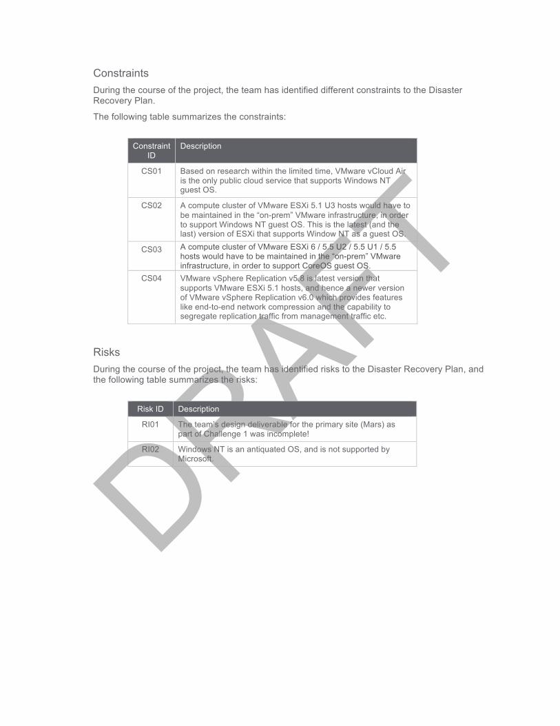
Constraints During the course of the project, the team has identified different constraints to the Disaster Recovery Plan.
The following table summarizes the constraints:
Constraint
ID Description
CS01 Based on research within the limited time, VMware vCloud Air is the only public cloud service that supports Windows NT guest OS.
CS02 A compute cluster of VMware ESXi 5.1 U3 hosts would have to be maintained in the “on-prem” VMware infrastructure, in order to support Windows NT guest OS. This is the latest (and the last) version of ESXi that supports Window NT as a guest OS.
CS03 A compute cluster of VMware ESXi 6 / 5.5 U2 / 5.5 U1 / 5.5 hosts would have to be maintained in the “on-prem” VMware infrastructure, in order to support CoreOS guest OS.
CS04 VMware vSphere Replication v5.8 is latest version that supports VMware ESXi 5.1 hosts, and hence a newer version of VMware vSphere Replication v6.0 which provides features like end-to-end network compression and the capability to segregate replication traffic from management traffic etc.
Risks During the course of the project, the team has identified risks to the Disaster Recovery Plan, and the following table summarizes the risks:
Risk ID Description
RI01 The team’s design deliverable for the primary site (Mars) as part of Challenge 1 was incomplete!
RI02 Windows NT is an antiquated OS, and is not supported by Microsoft.
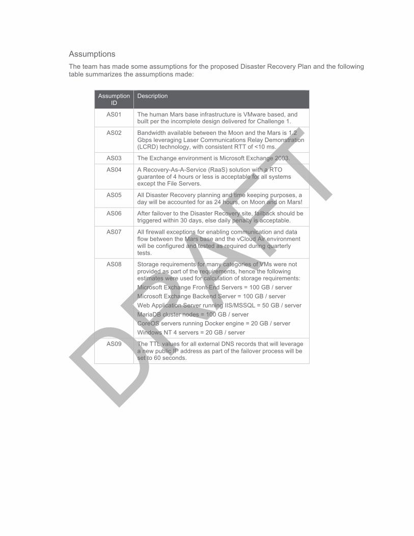
Assumptions The team has made some assumptions for the proposed Disaster Recovery Plan and the following table summarizes the assumptions made:
Assumption
ID Description
AS01 The human Mars base infrastructure is VMware based, and built per the incomplete design delivered for Challenge 1.
AS02 Bandwidth available between the Moon and the Mars is 1.2 Gbps leveraging Laser Communications Relay Demonstration (LCRD) technology, with consistent RTT of <10 ms.
AS03 The Exchange environment is Microsoft Exchange 2003.
AS04 A Recovery-As-A-Service (RaaS) solution with a RTO guarantee of 4 hours or less is acceptable for all systems except the File Servers.
AS05 All Disaster Recovery planning and time keeping purposes, a day will be accounted for as 24 hours, on Moon and on Mars!
AS06 After failover to the Disaster Recovery site, failback should be triggered within 30 days, else daily penalty is acceptable.
AS07 All firewall exceptions for enabling communication and data flow between the Mars base and the vCloud Air environment will be configured and tested as required during quarterly tests.
AS08 Storage requirements for many categories of VMs were not provided as part of the requirements, hence the following estimates were used for calculation of storage requirements: Microsoft Exchange Front-End Servers = 100 GB / server Microsoft Exchange Backend Server = 100 GB / server Web Application Server running IIS/MSSQL = 50 GB / server MariaDB cluster nodes = 100 GB / server CoreOS servers running Docker engine = 20 GB / server Windows NT 4 servers = 20 GB / server
AS09 The TTL values for all external DNS records that will leverage a new public IP address as part of the failover process will be set to 60 seconds.

SECTION 2: APPLICATION RTPO REQUIREMENTS
Microsoft Exchange Environment
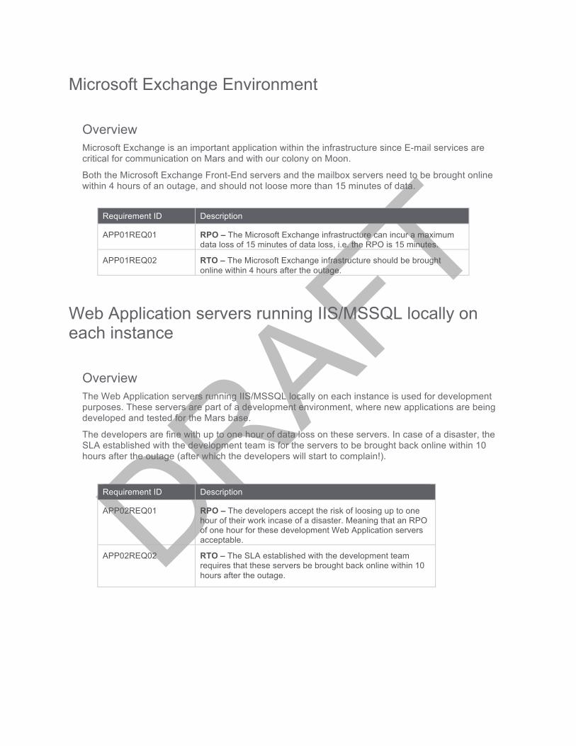
Overview Microsoft Exchange is an important application within the infrastructure since E-mail services are critical for communication on Mars and with our colony on Moon.
Both the Microsoft Exchange Front-End servers and the mailbox servers need to be brought online within 4 hours of an outage, and should not loose more than 15 minutes of data.
Requirement ID Description
APP01REQ01 RPO – The Microsoft Exchange infrastructure can incur a maximum data loss of 15 minutes of data loss, i.e. the RPO is 15 minutes.
APP01REQ02 RTO – The Microsoft Exchange infrastructure should be brought online within 4 hours after the outage.
Web Application servers running IIS/MSSQL locally on each instance
Overview The Web Application servers running IIS/MSSQL locally on each instance is used for development purposes. These servers are part of a development environment, where new applications are being developed and tested for the Mars base.
The developers are fine with up to one hour of data loss on these servers. In case of a disaster, the SLA established with the development team is for the servers to be brought back online within 10 hours after the outage (after which the developers will start to complain!).
Requirement ID Description
APP02REQ01 RPO – The developers accept the risk of loosing up to one hour of their work incase of a disaster. Meaning that an RPO of one hour for these development Web Application servers acceptable.
APP02REQ02 RTO – The SLA established with the development team requires that these servers be brought back online within 10 hours after the outage.

MariaDB cluster servers
Overview The MariaDB cluster is used to host the new census database on Mars. This database is actively queried from and written to by front-end systems on both the Moon and Mars bases. While the front-end systems are out of scope for this disaster recovery plan, the census database itself should be considered as a Tier 1 system for Disaster Recovery purposes. Data loss is not tolerable, due to the constant influx of humans to Mars, and the lack of processes to re-collect this data.
Requirement ID Description
APP03REQ01 RPO - The critical nature of the data gathered, holds the MariaDB cluster of servers to a RPO requirement of zero. Meaning that no data loss can be tolerated.
APP03REQ02 RTO – In case of a disaster at the Mars base, the MariaDB cluster should be consistently accessible for Reads/Write at the Moon base.
File servers
Overview The file servers are used to house home drive data for virtual desktop users for the Mars and Moon bases, along with sharing data between the two bases. Although the availability of the virtual desktop infrastructure itself is out of scope for this Disaster Recovery plan, it is imperative to be able to make these file servers actively available in the Disaster Recovery environment, as a means for sharing data with our colony on Moon.
The file servers need to need to be consistently available on Moon and on Mars active Reads / Writes, with bi-directional replication of changes. In case of a disaster a maximum of 15 minutes of data loss is acceptable.
Requirement ID Description
APP04REQ01 RPO - The maximum acceptable data loss for the changes made to the data hosted by the file servers is 15 minutes.
APP04REQ02 RTO – In case of a disaster in any of the sites, the other site should have the access to the data within 10 minutes.

CoreOS servers with Docker engine
Overview The CoreOS servers running the Docker engine are used to run instances of WordPress for our bloggers on Mars. They are very active bloggers, each trying to document their experiences on Mars, in different fields such as Healthcare, IT, Finance etc., such that others can learn from and collaborate on these experiences.
People who follow these blogs are hooked on to the content generated, and cannot tolerate these systems being unavailable for more than 4 hours. The bloggers are only able to remember the past 12 hours worth of events, hence it is necessary that in case of a disaster the systems are brought back online with no more than 12 hours of lost data.
Requirement ID Description
APP05REQ01 RPO - Since the bloggers cannot remember events older than 12 hours, the RPO for the CoreOS servers is 12 hours.
APP05REQ02 RTO – The people reading and following these blogs can only tolerate up to 4 hours of downtime in case of a disaster, hence the RTO is 4 hours.
Legacy Windows NT servers running IBM DB2
Overview The legacy Windows NT servers running IBM DB2 contains some of humanity’s census data, and these servers were converted into OVF templates and copied prior to leaving Earth. These are standalone servers and are not joined to a Windows NT 4.0 domain. The census data within the IBM DB2 database is in the process of being ported over to the new MariaDB based database. There are no active applications dependent on these servers, and the only users of this system are developers working on the migration of the data. And In case of a disaster, these servers can be one of the last services to be brought back online. There are no changes to the data stored in these systems, and is used for read-only purposes. The developers can be productive without these servers being available for up to a maximum of 48 hours.
Requirement ID Description
APP06REQ01 RPO – Since there are no changes being made to data on these servers, just a simple deployment from virtual machine template will suffice.
APP06REQ02 RTO - In case of a disaster, these servers should be brought back online in 48 hours, such that the developers can resume their work.

SECTION 3: THE CHOSEN DR SOLUTION – VMWARE VCLOUD
AIR As part of the proposed Disaster Recovery Plan, the team has chosen VMware vCloud Air public cloud services for BCDR operations on Moon. This choice was made after careful consideration to the project requirements, and long-term vision for infrastructure services for the human settlement on Mars, while leveraging our temporary Moon base for BCDR purposes. The disaster recovery plan leverages our “on-prem” VMware based infrastructure on the Mars Base as our Primary site. The primary drivers for selecting public cloud services delivered via VMware vCloud Air for the proposed Disaster Recovery plan are as follows:
• Since humanity has moved on to our Mars base, there are no more IT personnel left on the moon who have the know-how to deploy and maintain infrastructure, hence leveraging public cloud services for Disaster Recovery on the Moon is the strategic path forward.
• VMware vCloud Air integrates well with the “on-prem” VMware infrastructure and both support Windows NT guest OS. And based on the limited research the team has done, VMware ESXi and VMware vCloud Air is the only interoperable hypervisor and cloud service combination that supports the legacy Windows NT guest OS for virtual machines.
• vCloud Air On-Demand – We will leverage this utility based public cloud service for a “Pilot Light” environment that will be deployed for critical infrastructure components and strategic application components that will be constantly running in the public cloud. This will ensure that critical services required by the applications are available in the public cloud in case of a disaster.
• vCloud Air Disaster Recovery – This public cloud Recovery-as-a-Service (RaaS) gives us the subscription based compute, storage and network capacity required for failing over to the VPC if a disaster were to hit our Mars base.
• Multiple global facilities around the world, which can be leveraged for Disaster Recovery scenarios and planning.
• Dedicated “Direct Connect” links between the Mars base and the Moon base with 1 Gbps network bandwidth and low-latency (<10 ms) will be leveraged for replication of critical components and data between the Primary site (Mars) and the Disaster Recovery site (Moon).

15
Architecture The following logical diagram illustrates the high-level diagram wherein the primary Mars Base will leverage vCloud Air on our Moon base for Disaster Recovery purposes.

16
• The human IT infrastructure on Mars is based on the VMware infrastructure design conducted as part of Challenge 1.
• A VMware vCloud Air Region on Moon will be leveraged for Disaster Recover purposes. • Redundant Laser Communications Relay Demonstration (LCRD) links between the Moon and
Mars provided by Galacticast (Network Service Provider) will be leveraged for communication with 1 Gbps total available bandwidth and < 10 ms latency.
• Direct connect between the Mars base and the VMware vCloud Air service provided by Galacticast will be leveraged to provide consistent and predictable bandwidth of 1 Gbps and < 10 ms. latency. This is an important aspect of the design in order to achieve the RTPO requirements.
• The VMware vCloud Air On-Demand service will be leveraged for deploying a “Pilot Light” environment with necessary infrastructure components to facilitate disaster recovery, and in case of a disaster the VMware vCloud Air Disaster Recovery Service will be leveraged for failing over virtual machines from the Mars Base to the vCloud Air RaaS on the Moon.
• A VPN will be deployed between VMware vCloud Air On-Demand environment and the VMware vCloud Air Disaster Recovery environment, with associated routing, SNAT/DNAT, firewall rules etc. for successful communication.
• Microsoft Active Directory domain controllers will be deployed in the “Pilot Light” environment, comprising of two Active Directory Domain Controllers, one of them being a Global Catalog server. Appropriate Active Directory (AD) Sites and Services configuration will be performed, in order to reflect a secondary site with associated link costs to optimize AD replication traffic.
• Custom DHCP Options will be configured to leverage AD DNS services in the “Pilot Light” environment for the vCloud Air subnets.

17
SECTION 4: PRODUCTS AND TECHNOLOGIES LEVERAGED
18
VMware vCloud Air and “on-prem” components leveraged
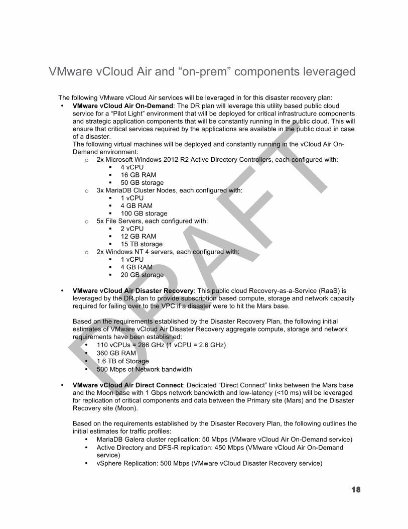
The following VMware vCloud Air services will be leveraged in for this disaster recovery plan: • VMware vCloud Air On-Demand: The DR plan will leverage this utility based public cloud
service for a “Pilot Light” environment that will be deployed for critical infrastructure components and strategic application components that will be constantly running in the public cloud. This will ensure that critical services required by the applications are available in the public cloud in case of a disaster. The following virtual machines will be deployed and constantly running in the vCloud Air On-Demand environment:
o 2x Microsoft Windows 2012 R2 Active Directory Controllers, each configured with: ! 4 vCPU ! 16 GB RAM ! 50 GB storage
o 3x MariaDB Cluster Nodes, each configured with: ! 1 vCPU ! 4 GB RAM ! 100 GB storage
o 5x File Servers, each configured with: ! 2 vCPU ! 12 GB RAM ! 15 TB storage
o 2x Windows NT 4 servers, each configured with: ! 1 vCPU ! 4 GB RAM ! 20 GB storage
• VMware vCloud Air Disaster Recovery: This public cloud Recovery-as-a-Service (RaaS) is
leveraged by the DR plan to provide subscription based compute, storage and network capacity required for failing over to the VPC if a disaster were to hit the Mars base.
Based on the requirements established by the Disaster Recovery Plan, the following initial estimates of VMware vCloud Air Disaster Recovery aggregate compute, storage and network requirements have been established:
• 110 vCPUs = 286 GHz (1 vCPU = 2.6 GHz) • 360 GB RAM • 1.6 TB of Storage • 500 Mbps of Network bandwidth
• VMware vCloud Air Direct Connect: Dedicated “Direct Connect” links between the Mars base
and the Moon base with 1 Gbps network bandwidth and low-latency (<10 ms) will be leveraged for replication of critical components and data between the Primary site (Mars) and the Disaster Recovery site (Moon).
Based on the requirements established by the Disaster Recovery Plan, the following outlines the initial estimates for traffic profiles:
• MariaDB Galera cluster replication: 50 Mbps (VMware vCloud Air On-Demand service) • Active Directory and DFS-R replication: 450 Mbps (VMware vCloud Air On-Demand
service) • vSphere Replication: 500 Mbps (VMware vCloud Disaster Recovery service)

19
The following components will be leveraged in the “on-prem” VMware infrastructure on Mars: • VMware vSphere Replication 5.8: VMware vSphere Replication is a requirement for replication
of virtual machine between the “on-prem” infrastructure and the vCloud Air public cloud service. This is the latest version of vSphere Replication that also supports all the versions of ESXi compute cluster hosts in-scope for this Disaster Recovery plan. The following VMware vSphere Replication settings will be configured for each group of virtual machines: Virtual machine category VMware vSphere Replication Policy
Microsoft Exchange Front-End and Mailbox servers
RPO: 15 minutes Point in time instances:
Instances per day: 6 Days: 4
Web Application servers running IIS/MSSQL locally
RPO: 1 Hour Point in time instances:
Instances per day: 4 Days:
CoreOS virtual machines to support Docker RPO: 12 hours Point in time instances:
Instances per day: 2 Days: 12
• VMware vCloud connector: VMware vCloud connector plug-in for VMware vCenter will be
leveraged for managing the “on-prem” infrastructure and the VMware vCloud Air public cloud infrastructure from a single-pane of glass i.e. vSphere.
• VMware ESXi 6.0: A compute cluster of VMware ESXi 6.0 nodes will be leveraged to run “CoreOS” based Docker engines.
• VMware vSphere 5.1 U3: A compute cluster of VMware ESXi 5.1 U3 nodes will be leveraged to run virtual machines with Windows NT as the guest OS.
• VMware vCenter Server 6.0: VMware vCenter Server 6.0 will be leveraged for the management of the “on-prem” infrastructure.
Microsoft Windows Server 2012 R2 Active Directory Services
• Two Microsoft Windows Server 2012 R2 domain controllers will be deployed in the VMware vCloud Air On-Demand environment, as part of the “Pilot Light” environment.

20
• One of the Domain Controllers in the “Pilot Light” Environment will be a Global Catalog server. • The Domain Controllers in the “Pilot Light” environment will be leveraged for internal DNS
services.
Microsoft DFS-R Microsoft Windows Server 2012 R2 DFS-R based data replication will be leveraged for the file servers, such that users from both the Moon base and the Mars base can access the data. And in case of a disaster at one site, the other site will still be able to access the all the data except for the last 15 minutes. • Five additional Windows Server 2012 R2 file servers will be deployed in the VMware vCloud Air
On-Demand environment on the Moon, to replicate the file server infrastructure on Mars. • DFS-R will be configured with all ten servers in the replication group, leveraging a hub and spoke
topology to optimize bandwidth utilization. • Based on the estimated traffic profile, bandwidth utilization for DFS-R replication will be
configured to be limited to 445 Mbps, which should be more than sufficient to achieve the RTPO requirements for the File Servers.
• A Domain-based DFS Namespace will provide a consistent shared folder path for accessing replicated shared folders on the Mars site (primary) nodes, or in the event of a disaster, the replica of those shared folders at the Moon site (DR).
• The Mars base (Primary site) and the Moon base (DR site) will each have one Namespace server added to the Namespace.
• Replication will be configured to 15 minute intervals 7 days a week, this will satisfy the RPO requirements.
MariaDB Galera cluster The MariaDB Galera cluster will be extended to the cloud by adding 3 more cluster nodes in the VMware vCloud Air On Demand environment. • The cluster will be configured for synchronous replication across the nodes to accommodate
RTPO requirements, considering the latency is <10 ms. • In order to optimize traffic flow, the Galera cluster will be configured into two segments, one in the
Mars Base (On-prem infrastructure) and the other in the Moon Base (vCloud Air infrastructure), each consisting of three cluster nodes each.
• The Relay Node in each segment will be responsible for WriteSet replication to the relay node in the other site.
• Based on the estimated traffic profile, bandwidth available for the MariaDB cluster WriteSet replication is 50 Mbps, which is expected to be more than sufficient for the rate of changes in the database.
21
SECTION 5: DISASTER RECOVERY PLAN - PROCESSES AND
PROCEDURES
22
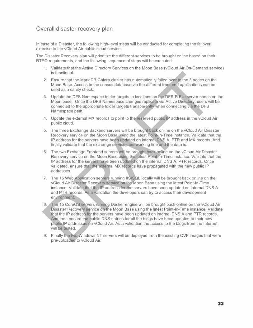
Overall disaster recovery plan
In case of a Disaster, the following high-level steps will be conducted for completing the failover exercise to the vCloud Air public cloud service.
The Disaster Recovery plan will prioritize the different services to be brought online based on their RTPO requirements, and the following sequence of steps will be executed:
1. Validate that the Active Directory Services on the Moon Base (vCloud Air On-Demand service) is functional.
2. Ensure that the MariaDB Galera cluster has automatically failed over to the 3 nodes on the Moon Base. Access to the census database via the different front-end applications can be used as a sanity check.
3. Update the DFS Namespace folder targets to locations on the DFS-R File server nodes on the Moon base. Once the DFS Namespace changes replicate via Active Directory, users will be connected to the appropriate folder targets transparently when connecting via the DFS Namespace path.
4. Update the external MX records to point to the reserved public IP address in the vCloud Air public cloud.
5. The three Exchange Backend servers will be brought back online on the vCloud Air Disaster Recovery service on the Moon Base using the latest Point-In-Time instance. Validate that the IP address for the servers have been updated on internal DNS A, PTR and MX records. And finally validate that the exchange services are working fine and the data is.
6. The two Exchange Frontend servers will be brought back online on the vCloud Air Disaster Recovery service on the Moon Base using the latest Point-In-Time instance. Validate that the IP address for the servers have been updated on the internal DNS A, PTR records. Once validated, ensure that the external MX records have propagated with the new public IP addresses.
7. The 15 Web Application servers running IIS/SQL locally will be brought back online on the vCloud Air Disaster Recovery service on the Moon Base using the latest Point-In-Time instance. Validate that the IP address for the servers have been updated on internal DNS A and PTR records. As a validation the developers can try to access their development environment.
8. The 15 CoreOS servers running Docker engine will be brought back online on the vCloud Air Disaster Recovery service on the Moon Base using the latest Point-In-Time instance. Validate that the IP address for the servers have been updated on internal DNS A and PTR records. And then ensure the public DNS entries for all the blogs have been updated to their new public IP addresses on vCloud Air. As a validation the access to the blogs from the Internet will be tested.
9. Finally the two Windows NT servers will be deployed from the existing OVF images that were pre-uploaded to vCloud Air.

23
SECTION 6: REFERENCES

Supplemental Information and Links
These links provide further information on the concepts and recommendations discussed during this document.
• Laser Communications Relay Demonstration (LCRD) – Brief description of the LCRD technology.
• VMware vCloud Air Documentation – Documentation for the VMware vCloud Air service. • VMware vCloud Air Cloud Computing Pricing Guide – This guide provides pricing for different
vCloud Air services. • VMware vCloud Air - Dedicated Connectivity – Direct Connect – Article outlining the vCloud
Air Direct Connect offering. • Windows NT 4.0 documentation covers information on how to install the operating system in a
virtual machine – Instructions on installing Windows NT 4 as a guest OS on VMware ESXi. • MariaDB Galera Clustering Use Cases – Article outlining details for Galera clustering for
MariaDB. • 5 Performance tips for running Galera Cluster for MySQL or MariaDB on AWS Cloud – Article
providing guidance for performance tuning mechanisms of Galera clusters. • Tuning replication performance in DFSR – Article outlining performance tuning techniques for
DFS-R replication. • DFS-R Topologies – Article outlining the different DFS-R topologies.