vised obstacle detection and multi robot object position...
TRANSCRIPT
r
Vision Based Obstacle Detection and Multi Robot Object Position Estimation
(December 2010)
Author: M ark Boulton
Supervisor: Professor Thomas B räunl
School of E lectr ical, E lectronic & Computer Engineering The University of Western Aust ralia
Vision Based Obstacle Detection and School of Electrical, Electronic and Computer Engineering Multi Robot Object Position Estimation The University of Western Australia
(i)
ABSTRACT As society becomes increasingly risk averse to placing people in potentially hazardous situations autonomous robotic systems technologies are being sought as a possible alternative. This is the motivation behind the Multi Autonomous Ground-robotic International Challenge (MAGIC) and in particular, this thesis is a description of several subsystems of a solution entered in the MAGIC 2010 competition.
In order for any autonomous robot to navigate through its environment, it must be able to avoid collisions with objects in the environment. In addition, for multiple robots to collaborate and find the same object in a newly mapped environment a solution that combines all object position reports and creates a single estimate for the position of these objects is essential.
This thesis describes issues associated with obstacle avoidance and position estimation for objects of interest, and presents implemented solutions to these problems. Also presented are the design, implementation and analysis of these systems as they relate to their integration into a MAGIC 2010 solution.
For obstacle avoidance, two solutions are presented, firstly one using colour histogram matching and the other using stereo vision with ground plane projection. Colour histogram matching assumes that all free path space around the robot will have a very similar colour histogram to that of the patch directly in front of the robot, quite a valid assumption in structured environments. The stereo vision solution takes advantage of the inherent 3D information in stereo imagery by creating a ground plane projection and thus finds objects that are above or below the ground plane.
An expectation maximisation algorithm is used as a solution to object position estimation for static objects of interest. To solve the same problem for mobile objects of interest a weighted average of position information is implemented.

Vision Based Obstacle Detection and School of Electrical, Electronic and Computer Engineering Multi Robot Object Position Estimation The University of Western Australia
(ii)
ACKNOWLEDGEMENTS First I must thank my supervisor Thomas Bräunl for the feedback and advice he provided, along with his continuing work to support students in the fields of robotics and autonomous systems.
Thanks must also go to Adrian Boeing and Aidan Morgan for their significant contribution throughout the year to support both myself but also all the other students and volunteers working on WAMBot for MAGIC 2010. Without their dedication this project would not have got off the ground or been the success it was.
Special thanks must go to Nicolas Garel with whom I spent a lot of time working on the vision systems and using the output of his detection software as the input into my Correlator. Nic, thanks for putting up with the many test runs and having to walk back and forth in the red suit!
I must also acknowledge the others student and many volunteers who put in such a huge effort to get WAMBot to the MAGIC 2010 finals. I was very proud to be part of such a fantastic, dedicated and capable team, well done everyone.
Finally but by no means least, I must thank my loving wife Melanie who put up with me disappearing to UWA for many weekends
for letting me follow my passion for this topic. Melanie, thank you! Also apologies to my girls Alexis, Destiny and Karin, I think I have some major playtime that is owed to you over the coming months.
Vision Based Obstacle Detection and School of Electrical, Electronic and Computer Engineering Multi Robot Object Position Estimation The University of Western Australia
(iii)
TABLE OF CONTENTS Abstract........................................................................................................................................ i Acknowledgements ..................................................................................................................... ii Table of Contents ....................................................................................................................... iii Table of Figures ......................................................................................................................... iv Table of Tables ........................................................................................................................... v Chapter 1. Introduction................................................................................................................ 1
1.1 Project Motivation ........................................................................................................ 1 1.1.1 MAGIC and WAMBot Goals ....................................................................... 1
1.2 Project Relevance ......................................................................................................... 3 1.3 Acronyms ..................................................................................................................... 4 1.4 Outline of this Thesis .................................................................................................... 5
Chapter 2. Background and Options ............................................................................................ 7 2.1 Obstacle Detection ........................................................................................................ 7
2.1.1 Passive Systems ........................................................................................... 7 2.1.2 Active Systems ............................................................................................. 7 2.1.3 Importance of Obstacle Detection ................................................................. 7 2.1.4 Literature ...................................................................................................... 8
2.2 Object Position Estimation ............................................................................................ 9 2.2.1 Importance of Position Estimation ................................................................ 9 2.2.2 Literature ...................................................................................................... 9
Chapter 3. VisIon - Theory ........................................................................................................ 11 3.1 Colour Histograms ...................................................................................................... 11 3.2 Stereo vision Idealistic Model ..................................................................................... 12 3.3 Stereo Camera Calibration .......................................................................................... 14
3.3.1 Intrinsic Parameters .................................................................................... 14 3.3.2 Extrinsic Parameters ................................................................................... 15
3.4 Ground Plane Projection ............................................................................................. 16 Chapter 4. Object Position Estimation ....................................................................................... 18
4.1 Position Estimation Errors .......................................................................................... 18 4.2 Expectation Maximisation .......................................................................................... 20
Chapter 5. Project ...................................................................................................................... 21 5.1 System Overview ........................................................................................................ 21 5.2 Robot Platform ........................................................................................................... 22
5.2.1 Hardware .................................................................................................... 22 5.2.2 Software ..................................................................................................... 23
Chapter 6. Obstacle Detection - Implementation ........................................................................ 24 6.1 Initial Hardware Configuration ................................................................................... 25 6.2 Vision System SW Framework ................................................................................... 25 6.3 Resolution .................................................................................................................. 25 6.4 Baseline Distance ....................................................................................................... 26 6.5 Camera Height ............................................................................................................ 26
Vision Based Obstacle Detection and School of Electrical, Electronic and Computer Engineering Multi Robot Object Position Estimation The University of Western Australia
(iv)
6.6 Calibration .................................................................................................................. 27 6.7 Obstacle Detection Design .......................................................................................... 28
6.7.1 Vision Control ............................................................................................ 31 6.7.2 Image Pre-Processing ................................................................................. 31 6.7.3 Obstacle Detection ..................................................................................... 31 6.7.4 Camera Calibration..................................................................................... 31
6.8 Implented Options ...................................................................................................... 32 6.8.1 Colour and Texture Matching ..................................................................... 32 6.8.2 Ground Plane Projection ............................................................................. 34
6.9 Improving the Results ................................................................................................. 38 Chapter 7. Object Location Correlation ..................................................................................... 40
7.1 Correlator Design ....................................................................................................... 40 7.1.1 Inputs ......................................................................................................... 40 7.1.2 Outputs ....................................................................................................... 41 7.1.3 Overview .................................................................................................... 41 7.1.4 Minimum Merge Distance .......................................................................... 43 7.1.5 Testing Strategy ......................................................................................... 43 7.1.6 Application Structure.................................................................................. 43
7.2 Implementation Results .............................................................................................. 44 7.3 Improving the Results ................................................................................................. 45
7.3.1 Global Pose ................................................................................................ 45 7.3.2 Mobile OOI Track ...................................................................................... 46
Chapter 8. Conclusions.............................................................................................................. 47 Appendix A. Bibliography ........................................................................................................ 48 Appendix B. System Requirements ........................................................................................... 51 Appendix C. Disparity and Baseline vs Distance ....................................................................... 55 Appendix D. Ground Plane Calculations ................................................................................... 58
TABLE OF FIGURES Figure 1.1 Possible final challenge phase layout .......................................................................... 3 Figure 3.1 Stereo image projection of single point between camera sensors ............................... 12 Figure 3.2 Stereo image projection of points between camera sensors ....................................... 13 Figure 3.3 Stereo camera setup on a base (or robot) ................................................................... 16 Figure 3.4 Left projected and original right image of doorway................................................... 17 Figure 4.1 Multi robot pose induced errors ................................................................................ 19 Figure 6.1 Left and right images of one set of calibration images .............................................. 27 Figure 6.2 Left and right original images ................................................................................... 28 Figure 6.3 Left and right images after calibration/rectification ................................................... 28
Vision Based Obstacle Detection and School of Electrical, Electronic and Computer Engineering Multi Robot Object Position Estimation The University of Western Australia
(v)
Figure 6.4 Stereo Vision Sub-Systems and Interfaces ................................................................ 30 Figure 6.5 Colour and texture matching examples ..................................................................... 33 Figure 6.6 Rectified left and right images .................................................................................. 35 Figure 6.7 Canny edge detector applied to images ..................................................................... 35 Figure 6.8 Ground Plane projection applied to left image .......................................................... 36 Figure 6.9 Highlighted areas indicate obstacles ......................................................................... 37 Figure 6.10 Bottom half of disparity map for previous image pairs ............................................ 38 Figure 6.11 Results combining GP obstacles with disparity maps .............................................. 38 Figure 7.1 Sample SOOI and MOOI detections ......................................................................... 41 Figure 7.2 OOI Correlator Sub-Systems and Interfaces ............................................................. 44 Figure 7.3 GCS HMI showing correlated OOIs ......................................................................... 45 Figure C.1 Disparity vs Distance for Different Baselines ........................................................... 57
TABLE OF TABLES Table 1.1 Acronyms .................................................................................................................... 4 Table 3.2 Example Hue vs Saturation Colour Histogram ........................................................... 11 Table C.3 Disparity vs Distance for Different Baselines ............................................................ 56 Table D.4 X left vs projects X left into right for different camera heights .................................. 58
Vision Based Obstacle Detection and School of Electrical, Electronic and Computer Engineering Multi Robot Object Position Estimation The University of Western Australia
1
CHAPTER 1. INTRODUCTION
The field of autonomous navigation is presented with many challenges to ensure that static, mobile and other obstacles above (including overhangs) and below (ditches and drop-offs) the ground plane are successfully navigated. In addition, a number of robots, working together to find and uniquely identify the same object in its environment is made extremely difficult due to the associated error introduced by each vehicle when identifying objects.
This thesis does not describe a pure research project but a solution to a set of given requirements in order to develop a solution to an existing engineering challenge.
1.1 PROJECT MOTIVATION
In 2010 The University of Western Australia combined with other local and interstate universities and local industry worked together to produce seven unmanned ground vehicles (robots). The competition was MAGIC 2010 (Multi Autonomous Ground-robotic International Challenge) and sponsored by the Australian Defence Science and Technology Organisation (DSTO). These robots needed to be able to autonomously explore and map out an urban environment (both indoors and out), find static and mobile objects of interest and neutralise them (DSTO D. S., 2010). An output of the system had to be a single map of the explored area. The solution developed is known by it WAMBot (Western Australian MAGIC Robotics Team).
The goal of the project was to build an Unmanned Ground Vehicle (UGV) that is capable of competing in MAGIC 2010 within a fixed budget. Ultimately, it was not possible to perform a full implementation of the stereo based obstacle detection system on the final UGV due to high cost of purchasing cameras of the required quality that could be used indoors and outdoors. As the stereo solution was not fully developed and made part of the final WAMBot solution, this thesis also includes work performed to solve issues with multi-robot object location correlation as they pertain to the MAGIC 2010 competition.
1.1.1 M A G I C and W A M Bot Goals
The goals set for the WAMBot project team are the goals for the MAGIC 2010 challenge itself which are:
Prepare a team of UGVs (Unmanned Ground Vehicles) that weigh in at less than 40kg,
Have these vehicles accurately and completely explore and map the challenge area for each of the 3 phases,
Vision Based Obstacle Detection and School of Electrical, Electronic and Computer Engineering Multi Robot Object Position Estimation The University of Western Australia
2
The UGVs with sensor packages must operate in an urban environment,
Correctly locate, classify and recognise all OOIs (Objects Of Interest) and simulated threats both static (SOOI) and mobile (MOOI),
Complete the 3 phases of the challenge within 3.5 hours, and
Minimise operator input to less than 10 minute across all three phases.
The three phases of the competition are designed to provide an increasing level of difficulty to the ic systems, with the final phase expected to also challenge the endurance of the UGVs, see (DSTO, 2010) for full details. In summary the phases are:
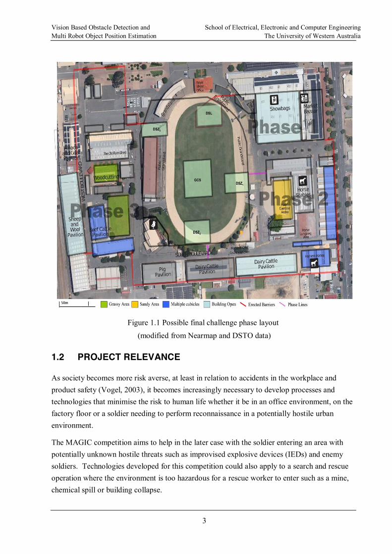
Phase 1 Covering an approximate area of 2.1 Ha this phase involves navigating primarily flat terrain in both GPS coverage and occluded areas. The indoor course will be challenging but environment will only have static objects of interest.
Phase 2 Covering an approximate area of 2.2 Ha with similar GPS constraints. Geographic layout of the buildings will be more complex and require vehicles to cover more distance to complete the mapping task. There will also be many small rooms with narrow entrances <1m. Both static and mobile objects of interest will be present.
Phase 3 Covering an approximate area of 4.9 Ha this phase is significantly larger with more complex terrain including large open areas, parked vehicles, curbs and poles. Sniper activity will be present in one area thus potentially stopping UGVs that stray into that area. Buildings will be larger and more complex to map.
The following Figure 1.1 represents an example of what was to be expected for the 3 phases in the finals of the MAGIC 2010 competition.
Vision Based Obstacle Detection and School of Electrical, Electronic and Computer Engineering Multi Robot Object Position Estimation The University of Western Australia
3
Figure 1.1 Possible final challenge phase layout (modified from Nearmap and DSTO data)
1.2 PROJECT RELEVANCE
As society becomes more risk averse, at least in relation to accidents in the workplace and product safety (Vogel, 2003), it becomes increasingly necessary to develop processes and technologies that minimise the risk to human life whether it be in an office environment, on the factory floor or a soldier needing to perform reconnaissance in a potentially hostile urban environment.
The MAGIC competition aims to help in the later case with the soldier entering an area with potentially unknown hostile threats such as improvised explosive devices (IEDs) and enemy soldiers. Technologies developed for this competition could also apply to a search and rescue operation where the environment is too hazardous for a rescue worker to enter such as a mine, chemical spill or building collapse.
Vision Based Obstacle Detection and School of Electrical, Electronic and Computer Engineering Multi Robot Object Position Estimation The University of Western Australia
4
Various forms of UGVs are already available (see (QinetiQ North America, 2010) as an example) that require an operator to either directly remote control the robot or set a series of waypoints for them to follow. A system though that could perform the same tasks autonomously with many UGVs only requiring minimal input from a single operator would make exploration and recognisance missions more productive due to the same or reduced time being required by the operator.
In order to achieve these autonomous systems there are technical problems that must be overcome such as navigation, collision avoidance, UGV collaboration and independent object of interest recognition. This thesis discusses collision avoidance and estimating OOI positions from multiple observations from multiple UGVs.
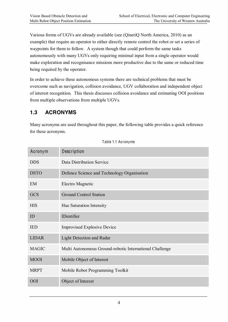
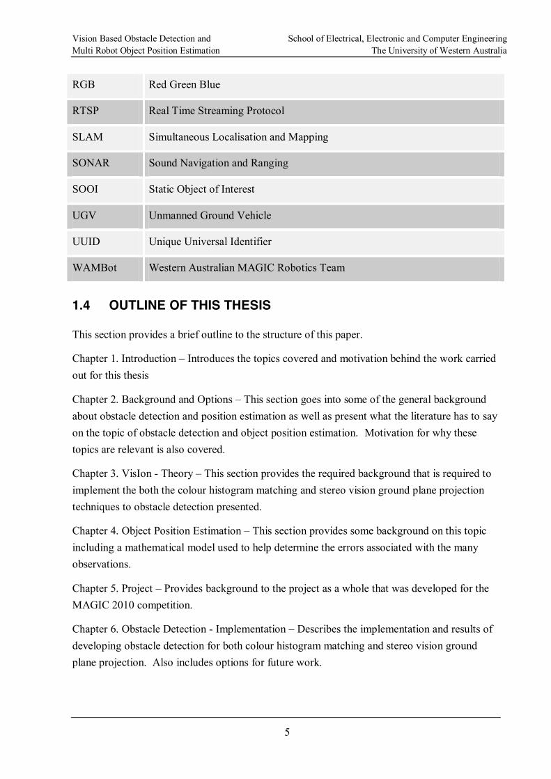
1.3 ACRONYMS
Many acronyms are used throughout this paper, the following table provides a quick reference for these acronyms.
Table 1.1 Acronyms
Acronym Description
DDS Data Distribution Service
DSTO Defence Science and Technology Organisation
EM Electro Magnetic
GCS Ground Control Station
HIS Hue Saturation Intensity
ID IDentifier
IED Improvised Explosive Device
LIDAR Light Detection and Radar
MAGIC Multi Autonomous Ground-robotic International Challenge
MOOI Mobile Object of Interest
MRPT Mobile Robot Programming Toolkit
OOI Object of Interest
Vision Based Obstacle Detection and School of Electrical, Electronic and Computer Engineering Multi Robot Object Position Estimation The University of Western Australia
5
RGB Red Green Blue
RTSP Real Time Streaming Protocol
SLAM Simultaneous Localisation and Mapping
SONAR Sound Navigation and Ranging
SOOI Static Object of Interest
UGV Unmanned Ground Vehicle
UUID Unique Universal Identifier
WAMBot Western Australian MAGIC Robotics Team
1.4 OUTLINE OF THIS THESIS
This section provides a brief outline to the structure of this paper.
Chapter 1. Introduction Introduces the topics covered and motivation behind the work carried out for this thesis
Chapter 2. Background and Options This section goes into some of the general background about obstacle detection and position estimation as well as present what the literature has to say on the topic of obstacle detection and object position estimation. Motivation for why these topics are relevant is also covered.
Chapter 3. VisIon - Theory This section provides the required background that is required to implement the both the colour histogram matching and stereo vision ground plane projection techniques to obstacle detection presented.
Chapter 4. Object Position Estimation This section provides some background on this topic including a mathematical model used to help determine the errors associated with the many observations.
Chapter 5. Project Provides background to the project as a whole that was developed for the MAGIC 2010 competition.
Chapter 6. Obstacle Detection - Implementation Describes the implementation and results of developing obstacle detection for both colour histogram matching and stereo vision ground plane projection. Also includes options for future work.

Vision Based Obstacle Detection and School of Electrical, Electronic and Computer Engineering Multi Robot Object Position Estimation The University of Western Australia
6
Chapter 7. Object Location Correlation Describes the implementation and results for the multiple robot position estimation problem. Also includes options for future work.
Chapter 8. Conclusions Provides a brief summary of the results for the project.
Appendices Includes bibliography, tables of relevant calculations, results and justifications for statements made in the main text.
Vision Based Obstacle Detection and School of Electrical, Electronic and Computer Engineering Multi Robot Object Position Estimation The University of Western Australia
7
CHAPTER 2. BACKGROUND AND OPTIONS
2.1 OBSTACLE DETECTION
Active or passive sensors systems are both viable options for the detection of obstacles in the environment.
A passive sensor system is any system that uses energy (magnetic, electrical, etc) that is either reflected or emitted from objects in the environment to determine information about the scene. This is in contrast to an active sensor system that emits EM energy that is then reflected off objects in the scene to then be collected and used to determine information about the scene.
2.1.1 Passive Systems
Vision, using either mono or stereo cameras, is a common passive sensor for the detection of obstacles in the environment. The big advantage of the passive system is that a large spatial resolution in both the horizontal and vertical directions (Discant, Rogozan, Rusu, & Bensrhair, 2007).
The primary disadvantage of vision based systems is that the scene has to be interpreted to determine the required information.
2.1.2 Active Systems
Light Detection and Ranging (LIDAR) systems are amongst some of the more accurate devices for the collection of information about a scene. SONAR (Sound Navigation And Ranging) is another method for detecting objects in the scene but tend not to work well in an outdoor environment.
A LIDAR system is quite accurate compared to a vision based system at determining the range to an object but they are restricted to a single plane (Froehlich, Mettenleiter, & Haertl, 1997). Thus to collect information about the entire scene either a system with many planes or a system that moves the single plane are required.
2.1.3 Importance of Obstacle Detection
In everyday life, people move about their environment in relative ease, seeing and avoiding objects and obstacles with which they might collide. This comes very easily to almost everyone but duplicating this in a robotics system has proven to be quite difficult, (Rankin, Huertas, & Matthies, 2005) shows performance of many systems but still none of them perfect.
If a UGV is going to be successfully in completing its objective of exploring an unknown environment, it must be able to avoid collisions with the environment, whether they are poles,
Vision Based Obstacle Detection and School of Electrical, Electronic and Computer Engineering Multi Robot Object Position Estimation The University of Western Australia
8
ditches, walls or other unknown types of obstacles. The need for a robust solution to this problem could ultimately determine success or failure of the mission as, if the UGV falls down a ditch it is no longer able to perform its task and is potentially may lead to the loss of an expensive item of technology.
2.1.4 Literature
There are many papers related to obstacle detection, discussed below are a few examples related to the use of colour histogram matching and stereo vision.
The paper (Rankin, Huertas, & Matthies, 2005) provides a good overview of some of the techniques available for obstacle detection in an outdoor environment. The paper covered obstacle detection for water hazards, tree trunks, excessive slope, range density based (to remove false positives of vegetation such as tall grass), positive (obstacle sticking up out of the ground), negative (ditches) and low overhanging. They present a table where they show good
positive and tree trunk algorithms. The paper does give a good overview of the problem of obstacle detection by making it clear that a one size fits all approach is not feasible. There is not much in the way of details for algorithms to support the results so it is not possible to duplicate what they have achieved.
A method of obstacle detection is the use of colour histograms to find a free path with (Ulrich & Nourbakhsh, July/August 2000) being a good example of this technique. This paper makes some assumptions about the environment including:
Obstacles differ in appearance from the ground,
The ground is relatively flat, and
There are no overhanging obstacles.
This paper describes how the generation of a colour histogram from a patch in front of the robot can be used as a template to find areas with a very similar histogram in the rest of the image. Such a process should result in finding a clear path for the UGV to traverse. The process/algorithms described and assumptions made can be applied to help achieve the goals of this project except that it cannot be guaranteed that the ground in front of the robot will not contain debris on it that will cause false positives.
Although block matching stereo correspondence algorithms did not need to be designed and implemented in their own right as they formed part of the OpenCV library, the paper (Birchfield & Tomasi, 1998) is a good reference of the theory behind this. This paper presents the issues associated with finding pixel correspondence between stereo images and generating a
Vision Based Obstacle Detection and School of Electrical, Electronic and Computer Engineering Multi Robot Object Position Estimation The University of Western Australia
9
disparity map. The methods described correspond with the approach taken with the use of stereo cameras in this paper with stereo image pairs being row aligned.
The paper (Mandelbaum, McDowell, Bogoni, Beich, & Hansen, 1998) although not particularly detailed does support the use of disparity map and mapping of what is thought to be ground plane between left and right images.
In the paper (Konolige, Oct, 1997) shows some good early work in the use of row aligned images and computing a disparity map. In particular an excellent example in figure 4 is shown of the problems that are encountered if images are misaligned vertically by just two rows.
In (Li & Brady, July, 1998) an excellent description of the ground plane transformation is presented. A detailed analysis shows how the transform can be applied to a generic stereo cameras setup with multiple joints and angles plus how this can be applied to a system where these angles can be changed during the operation of the system.
2.2 OBJECT POSITION ESTIMATION
2.2.1 Importance of Position Estimation
In both military and civilian scenarios, the ability for multiple UGV to have automatic generation of the position of OOIs found in the environment is more than just a nice to have.
If the situation in which no single system is correlating position observations from multiple UGVs is considered then the only alternative is to have a human operator look at each observation and determine if it is the same OOI and if so have the system merge it with other observations of the same object. This is time consuming and likely to be error prone when the system has many UGVs all reporting on the same object. Even if each UGV only reports an OOI position once it would still be time consuming for an operator to manually merge the various OOI observations together.
It is for this reason that a solution and implementation to this problem are presented in this thesis.
2.2.2 Literature
The subject of multiple robot object position estimation is not well covered for the general case of finding zero or more objects in the environment of different types. Much of the literature instead relates to such special cases as robot soccer where a single known object is being tracked and a position estimated for it. For this project this topic also covers both static and mobile objects, both of which require different techniques to determine the object positon.
Vision Based Obstacle Detection and School of Electrical, Electronic and Computer Engineering Multi Robot Object Position Estimation The University of Western Australia
10
An algorithm is required in order to estimate a position from multiple observations of the same object. In (Bilmes, 1998) the theory behind and justification for an expectation maximisation algorithm is put forward parameter estimation being applied to a Gaussian distribution.
In (Ferrein, Hermanns, & Lakemeyer, 2006) various algorithms are tested to determine the current location of the soccer ball in robot soccer. As might be expected algorithms such as a Kalman filter proved effective with the least amount of error as they could obviously use prior information and the motion of a ball to better evaluate where it might next be located.
Similarly the paper (Stroupe, Martin, & Balch, 2001) also discusses soccer ball position estimation but also includes details on the various error that are introduced as part of a single robot determining the current location of the ball and following on with the impact on multiple robot ball position estimation.
Vision Based Obstacle Detection and School of Electrical, Electronic and Computer Engineering Multi Robot Object Position Estimation The University of Western Australia
11
CHAPTER 3. VISION - THEORY
To be able to find obstacles in the environment it is first necessary to determine or extrapolate 3D information about the environment.
3.1 COLOUR HISTOGRAMS
The output from most image sensors is a 2D matrix of red, green and blue (RGB) values, one for each pixel of the image. The HSI values are independent so that an increase in the brightness in an image does not necessarily change the colour (HS) of the object being observed. In order for the colour information in an image to be useful for finding similar colours in the same or a different image (Zhang & Wang, 2000) these RGB values must be converted to hue, saturation and intensity (HSI). This must be done as colour information in HS space is not impacted by the brightness of the scene.
The colour histogram is different to what may be the more common image or intensity histogram. The intensity histogram provides the number of pixels in an image for each of the available intensity levels. For a black and white image, this will simply be the two values, one for the black level and one for the white level.
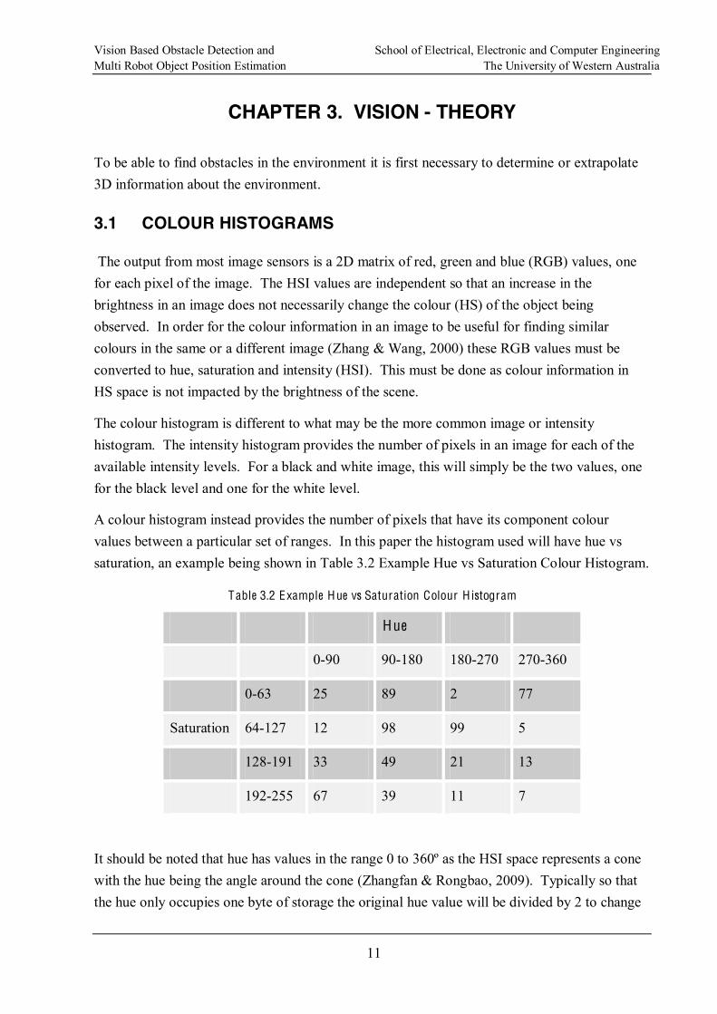
A colour histogram instead provides the number of pixels that have its component colour values between a particular set of ranges. In this paper the histogram used will have hue vs saturation, an example being shown in Table 3.2 Example Hue vs Saturation Colour Histogram.
Table 3.2 Example Hue vs Saturation Colour H istogram
Hue
0-90 90-180 180-270 270-360
0-63 25 89 2 77
Saturation 64-127 12 98 99 5
128-191 33 49 21 13
192-255 67 39 11 7
It should be noted that hue has values in the range 0 to 360º as the HSI space represents a cone with the hue being the angle around the cone (Zhangfan & Rongbao, 2009). Typically so that the hue only occupies one byte of storage the original hue value will be divided by 2 to change
Vision Based Obstacle Detection and School of Electrical, Electronic and Computer Engineering Multi Robot Object Position Estimation The University of Western Australia
12
the range to 0-180º, this is important when processing images in the HSI space (Bradski & Kaehler, 2008).
The purpose of computing the colour histogram is that it provides a colour description of the image area that was processed. This histogram can be compared, using various techniques such as earth movers distance (Ling & Okada, 2007) or back projection (Lee, Lee, & Jeong, 2003), to histograms of other sample areas or compared to a previously generated histogram to determine if the histograms match. This match may indicate that the areas being looked at are part of the same object (Ulrich & Nourbakhsh, July/August 2000).
3.2 STEREO VISION IDEALISTIC MODEL
Stereo vision is a method by which 3D scene information is reconstructed from different views of the scene from two, typically displaced horizontally, cameras.
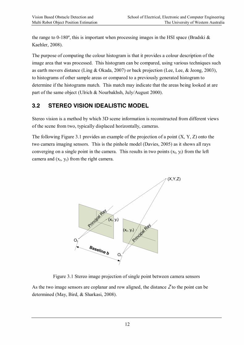
The following Figure 3.1 provides an example of the projection of a point (X, Y, Z) onto the two camera imaging sensors. This is the pinhole model (Davies, 2005) as it shows all rays converging on a single point in the camera. This results in two points (xl, yl) from the left camera and (xr, yr) from the right camera.
Princip
al Ray
Princip
al Ray
Ol
Or
(xl, yl)
(xr, yr)
(X,Y,Z)
Baseline b
Figure 3.1 Stereo image projection of single point between camera sensors
As the two image sensors are coplanar and row aligned, the distance Z to the point can be determined (May, Bird, & Sharkasi, 2008).
Vision Based Obstacle Detection and School of Electrical, Electronic and Computer Engineering Multi Robot Object Position Estimation The University of Western Australia
13
Baseline bOl
Prin
cipa
l Ray
Prin
cipa
l Ray
Or
xl1 xr1
Z2
Z1
P1
P2
f
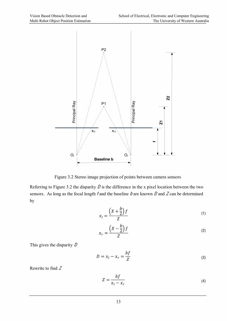
Figure 3.2 Stereo image projection of points between camera sensors
Referring to Figure 3.2 the disparity D is the difference in the x pixel location between the two sensors. As long as the focal length f and the baseline b are known D and Z can be determined by
(1)
(2)
This gives the disparity D
(3)
Rewrite to find Z
(4)
Vision Based Obstacle Detection and School of Electrical, Electronic and Computer Engineering Multi Robot Object Position Estimation The University of Western Australia
14
It can be seen then that the disparity D is inversely proportional to the distance Z to the point being viewed and proportional to the distance between the camera centres b.
The problem when using disparity to determine distance to an object is the discontinuity in the disparity value (Birchfield & Tomasi, 1999). As the discontinuity is based on physical pixels in the image sensor, it is not possible to end up with a non-integer disparity of say 36.827. Examining the sample data in Appendix C. Disparity and Baseline vs Distance, the impact of this discontinuity is seen particularly on smaller disparity values. This data also shows the impact of increasing the baseline distance between the cameras. It may appear beneficial to separate the cameras as much as possible to reduce the discontinuity at greater distances but problems with occlusion and finding points of correspondence increase (Chang, Chatterjee, & Kube, 1991).
The pinhole model is considered idealistic (Davies, 2005) because it is not possible (extremely impractical) to have two cameras that are truly row aligned across the whole image and coplanar.
3.3 STEREO CAMERA CALIBRATION
The problem with the idealistic model is that it is not possible to simply obtain two cameras off the shelf and use them in this manner. Camera pairs must be calibrated so that the idealistic model can be applied.
To calibrate a stereo camera configuration both extrinsic and intrinsic parameters associated with the setup and the cameras themselves must be taken into consideration.
The intrinsic parameters define the correction required to:
Image sensor centre offset from focal centre of lens, and
Lens distortion.
The extrinsic parameters define the correction required to:
Image sensor planes to become coplanar, and
Image sensor planes to become row aligned.
3.3.1 Intrinsic Parameters
To be able to treat a camera in the pinhole model described previously it is necessary to correct for any image sensor misplacement or lens distortion in the camera (Bradski & Kaehler, 2008).
Vision Based Obstacle Detection and School of Electrical, Electronic and Computer Engineering Multi Robot Object Position Estimation The University of Western Australia
15
If the image sensor is not positioned at exactly the centre of the lenactual centre pixel location on the image centre will be offset. The following two equations provide the translated/corrected centre location:
(5)
(6)
where:
xcorrected and ycorrected are the actual location of a pixel corrected for X and Y centre offset.
fx and fy are the focal length of the lens in the X and Y direction.
cx and cy are the actual image sensor centre offsets for the lens principal ray.
X, Y and Z is the real word location of the point being projected.
The correction for camera distortion is a significantly more complex issue and is outside the scope of this paper, please refer to (Bradski & Kaehler, 2008).
In short thought the projection of a point in space onto an image sensor, ie world coordinates onto pixel coordinates can be defined as:
(7)
Where A is:
(8)
and R and T are the rotation and translation matrices correcting the lens distortion.
3.3.2 Ext rinsic Parameters
To be able to work with calibrated stereo cameras it is necessary to determine what rotation and translation are required to move the left image sensor onto the right image sensor (or vice versa). This allows for the required determination of differences between the images to draw out 3D information.
The Essential Matrix captures the extrinsic parameters.
Vision Based Obstacle Detection and School of Electrical, Electronic and Computer Engineering Multi Robot Object Position Estimation The University of Western Australia
16
As for the full intrinsic matrix, the full definition can be found in (Davies, 2005)
3.4 GROUND PLANE PROJECTION
The ground plane is the plane of points that represents the flat ground (Se & Brady, 2002).
For a group of points in 3D that exist on the ground plane a transform will map the left image of a stereo image pair onto the right image sensor. Points that did not originate on the ground plane are displaced in the transformed image and can be used to identify regions that are above or below the ground plane.
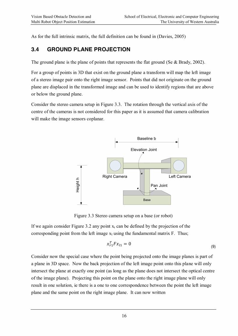
Consider the stereo camera setup in Figure 3.3. The rotation through the vertical axis of the centre of the cameras is not considered for this paper as it is assumed that camera calibration will make the image sensors coplanar.
Base
Baseline b
Elevation Joint
Pan Joint
Right Camera Left Camera
Hei
ght h
Figure 3.3 Stereo camera setup on a base (or robot)
If we again consider Figure 3.2 any point xr can be defined by the projection of the corresponding point from the left image xl using the fundamental matrix F. Thus;
(9)
Consider now the special case where the point being projected onto the image planes is part of a plane in 3D space. Now the back projection of the left image point onto this plane will only intersect the plane at exactly one point (as long as the plane does not intersect the optical centre of the image plane). Projecting this point on the plane onto the right image plane will only result in one solution, ie there is a one to one correspondence between the point the left image plane and the same point on the right image plane. It can now written
Vision Based Obstacle Detection and School of Electrical, Electronic and Computer Engineering Multi Robot Object Position Estimation The University of Western Australia
17
(10)
where Fp is the projection matrix for the plane being considered.
For details on applying this to our model in Figure 3.3 refer to (Li & Brady, July, 1998). For the special case where the cameras do not rotate about their vertical centre, their image planes are perpendicular to the ground plane and where the camera pair does not rotate about the pan joint the result is
(11)
Referring to Appendix D. Ground Plane Calculations it can be seen that as the cameras are moved higher above the ground that the projection of the left onto the right leads to a loss of information as the mapping becomes less and less influenced by the y (height in the image) pixel location.
From equation (11) it is known that as the height h increases the influence of the height of the pixel in the image is reduced, this impacts the ability for any further ground plane processing to find the discontinuities between the original right image and the projected left image.
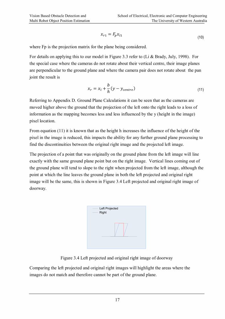
The projection of a point that was originally on the ground plane from the left image will line exactly with the same ground plane point but on the right image. Vertical lines coming out of the ground plane will tend to slope to the right when projected from the left image, although the point at which the line leaves the ground plane in both the left projected and original right image will be the same, this is shown in Figure 3.4 Left projected and original right image of doorway.
Left ProjectedRight
Figure 3.4 Left projected and original right image of doorway
Comparing the left projected and original right images will highlight the areas where the images do not match and therefore cannot be part of the ground plane.
Vision Based Obstacle Detection and School of Electrical, Electronic and Computer Engineering Multi Robot Object Position Estimation The University of Western Australia
18
CHAPTER 4. OBJECT POSITION ESTIMATION
For a fixed robot system where a the object classification system is providing location information that relates to the same object, the two main sources of error for the position are the distance from the robot to the object and the angle off centre of the object in the vision system (Stroupe, Martin, & Balch, 2001). Errors in these two parameters can be modelled on a Gaussian distribution making object position estimation easier. For a mobile robot performing
in its current position and heading (pose1) also has error associated with how this pose was determined, which presents more problems when combined with the previously mentioned errors.
If given separate observations of what may be the same object from a different mobile robot or from the same mobile robot that has lost and then found the same object again (but has not detected it) a system is needed to correlate these observations and merge them if they are considered statistically close, ie the same object.
4.1 POSITION ESTIMATION ERRORS
Observations of the OOI have a number of sources of error that must be mitigated to produce a final global estimate of the OOI position. The OOI observations have the following main sources of error:
Inaccurate estimation of distance and angle
Occluded observations
Inaccuracies in a UGV local pose
will be within a certain error bounds relative to all other UGVs
Errors associated with the distance and angle measures can be system specific as the technologies used can have quite an impact on the accuracy of these measurements. LIDAR for example will typically measure distance to an accuracy of 3cm where as a vision based approach will become less accurate with increasing distance (see Appendix C. Disparity and Baseline vs Distance). Any error model applied to this will be system dependant.
1 Strictly speaking, the pose should also include the roll, pitch, yaw and elevation but for this discussion the
most importance.
Vision Based Obstacle Detection and School of Electrical, Electronic and Computer Engineering Multi Robot Object Position Estimation The University of Western Australia
19
local pose, ie its position and heading, any error introduced in this pose, e.g. encoder drift, over time will introduce error into the observations made by the UGV (Zhou & Chirikjian, 2003).
If the actual global pose of a UGV does not match what the UGV believes to be its global pose then objects will be detected out of position. The amount of error is dependent on how far out the UGV estimate of its global pose is compared to what it actually is. Again a model to determine such errors is difficult.
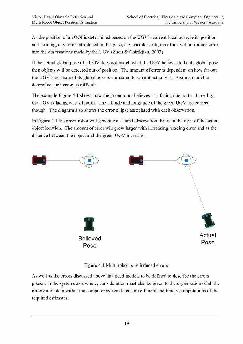
The example Figure 4.1 shows how the green robot believes it is facing due north. In reality, the UGV is facing west of north. The latitude and longitude of the green UGV are correct though. The diagram also shows the error ellipse associated with each observation.
In Figure 4.1 the green robot will generate a second observation that is to the right of the actual object location. The amount of error will grow larger with increasing heading error and as the distance between the object and the green UGV increases.
BelievedPose
ActualPose
Figure 4.1 Multi robot pose induced errors
As well as the errors discussed above that need models to be defined to describe the errors present in the systems as a whole, consideration must also be given to the organisation of all the observation data within the computer system to ensure efficient and timely computations of the required estimates.
Vision Based Obstacle Detection and School of Electrical, Electronic and Computer Engineering Multi Robot Object Position Estimation The University of Western Australia
20
4.2 EXPECTATION MAXIMISATION
This section provides some background of the theory behind this process although it is not meant to be a comprehensive description of expectation maximisation algorithms. For a comprehensive description of expectation maximisation algorithms see (Bilmes, 1998) and for an application see (Pulford & Logothetis, 1997).
An expectation maximisation algorithm is a method for finding the unknown parameters of a statistical model through maximum likelihood estimates. The expectation maximisation algorithm is an iterative method firstly performing an expectation step using log likelihood estimate of the current unknown parameters followed by a maximisation step that determines the values by maximising the expected log likelihood found in the expectation step. This process is repeated across several iterations until the parameters found stabilise.
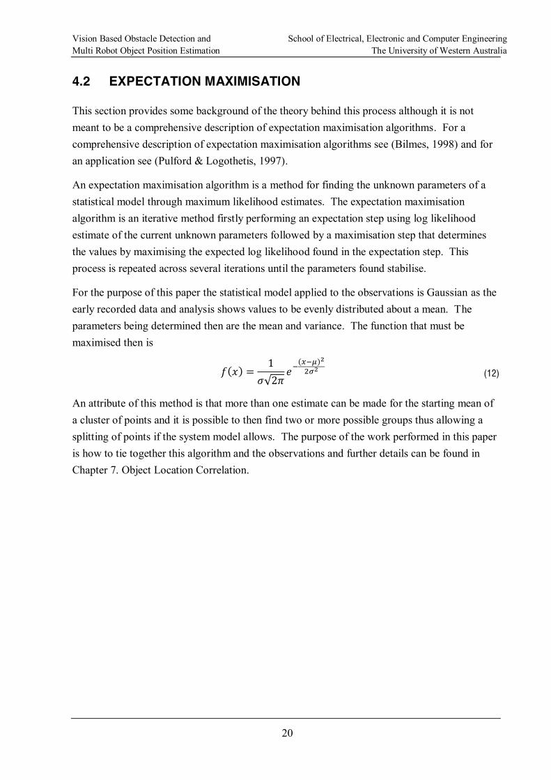
For the purpose of this paper the statistical model applied to the observations is Gaussian as the early recorded data and analysis shows values to be evenly distributed about a mean. The parameters being determined then are the mean and variance. The function that must be maximised then is
(12)
An attribute of this method is that more than one estimate can be made for the starting mean of a cluster of points and it is possible to then find two or more possible groups thus allowing a splitting of points if the system model allows. The purpose of the work performed in this paper is how to tie together this algorithm and the observations and further details can be found in Chapter 7. Object Location Correlation.
Vision Based Obstacle Detection and School of Electrical, Electronic and Computer Engineering Multi Robot Object Position Estimation The University of Western Australia
21
CHAPTER 5. PROJECT
As mentioned in 1.1 Project Motivation, the work described here is in support of the WAMBot project. As this is the first year that such an attempt has been made the goals of the system as a whole were to develop a system from scratch that could achieve the MAGIC 2010 objectives.
As previously described, this paper discusses solutions to obstacle detection and multiple robot object correlation.
5.1 SYSTEM OVERVIEW
The following is a brief description of how the system is designed and what various systems make up the final solution.
The UGVs are broken up into two types of vehicles, Sensors and Disruptors. Sensors are required to perform all exploration, mapping and object detection tasks. The Disruptor vehicles
generated map so that it can find its way to the object.
The system as a whole is controlled from the Ground Control Station using wireless communications1 to collect and control the various operations of the UGVs.
The key sub-systems are:
Localisation determine where in the environment the UGV is currently. Incorporates mapping of the environment (SLAM).
Vision take data from the cameras and process it to find obstacles, objects of interest and track objects of interest.
Object tracking once the vision system detects an object it is tracked for as long as it is maintained within the field of view of the vision systems camera, this applies to static and mobile objects with the UGV stationary or moving.
Map builder on the UGV it builds the local map, on the GCS it merges the maps into a single map that is distributed to the UGVs for use during exploration.
Exploration AI component to ensure that all areas are mapped out.
1 The final system uses a multiple hop, dynamic mesh network on top of an 802.1g wireless infrastructure.
Vision Based Obstacle Detection and School of Electrical, Electronic and Computer Engineering Multi Robot Object Position Estimation The University of Western Australia
22
Path planner plots a path on the local map to use to move the UGV to a location commanded by Exploration or an operator on the GCS (waypoint).
Correlation merges object detection information from many sources into a merged view of the objects also maintaining state information about the correlated objects.
Communications provide the required wireless communications between the Rangers, Disruptors and Ground Control Station. Communications also includes the Data Distribution System used to communicate between the separate systems mentioned here.
Drivable surface detection determine if the path in front of the robot can be safely traversed.
GCS HMI the interface presented to the user to control how the exploration, mapping and neutralisation processes are carried out.
E-Stop a method to safely stop the UGV if required.
A subset of the full requirements relating to the solutions this paper presents are details in Appendix B. System Requirements. The above list of sub-systems are not all required to achieve the given subset of system requirements but are required to achieve the goals of the system as a whole.
5.2 ROBOT PLATFORM
Following is a description of the hardware and software used to develop and operate the WAMBot system.
5.2.1 Hardware
The robots use the following key hardware components:
Pioneer P3AT for the robot base,
Mo-Co-So MiniITX automotive PC on board robot x86 based computing platform,
SICK LMS 111 laser scanner for mapping of the surrounding environment, scan line set about 50cm above the ground,
Hokuyo URG-04LX-UG01 lower end laser scanner mounted vertically for ground profile information,
IBEO Lux used for assisting in the detection of mobile objects of interest, ie people,
Logitech Sphere AF primary camera sensor for the system,
Vision Based Obstacle Detection and School of Electrical, Electronic and Computer Engineering Multi Robot Object Position Estimation The University of Western Australia
23
QStarz BT-Q818X NEMA compliant GPS receiver,
XSenS MTi IMU Inertial Measurement Unit, used for compass and additional input into localisation system,
AXIS M3114-R direct network attach camera (uses RTSP) for remote user operation of the robot, and
PICO Station Wireless AP mesh enabled 2.4GHz wireless access point.
5.2.2 Software
The following key software packages are used on the system
Windows XP this was the operation system for the UGV computing platform and the GCS.
Microsoft Visual Studio 2008 this platform is required for C++ development, debugging, etc.
IntelliJ IDEA this platform is required for the Java development.
RTI Data Distribution Service provided the interface to send SW objects between the various sub-system applications.
OpenCV provided the infrastructure for the vision system.
MRPT provided the infrastructure to support the mobile robot platform.
NOTE: Software and configuration files developed for this thesis and for the project as a whole, are stored in an online version control system.
Vision Based Obstacle Detection and School of Electrical, Electronic and Computer Engineering Multi Robot Object Position Estimation The University of Western Australia
24
CHAPTER 6. OBSTACLE DETECTION - IMPLEMENTATION
For this project, the required outcome from the obstacle detection system is the detection of objects or terrain that must be avoided in order to have a traversable path for the UGV. As the laser scanner has a single line output horizontal to the ground and approximately 50cm above it, anything above or below this plane is not be detected by the SLAM system. There are also obstacles that are not always detected1 by the laser scanner, such as table legs and some types of mesh fencing, even though they are at a height which would allow for detection by the laser scanner.
To design a solution for obstacle detection there were several proposals put forward:
Mount the SICK laser scanner on a motorised pivoting head that would tip the unit forward and backwards so that it can detect obstacles close to the ground.
Use a vision system to allow enable colour histogram mapping to find a clear path.
Use stereo vision provide required 3D scene information and thus detect objects above or below the ground plane.
Mount a separate laser scanner tilted permanently downward.
Use a second laser scanner mount with its beam in the vertical plane pointing straight ahead of the UGV.
The solution that was decided on was stereo vision, as with a single set of stereo images it is possible to extract obstacle and distance data from the scene. All the other options would require a temporal solution, ie analysis of data over time to build up a model of the terrain around the UGV. A temporal solution is always more difficult for a mobile robotic system as
nt any movement of the UGV since the previous sensor sweep when integrating the many data sets.
A stereo vision based approach to obstacle detection also meant that objects of interest, once found in the scene, could have their distance readily extracted from the disparity map for the detected object. Distances measurements of 20m (greater distances would be an advantage though) are required for this solution.
1 The limitations were determined in early testing of the system.
Vision Based Obstacle Detection and School of Electrical, Electronic and Computer Engineering Multi Robot Object Position Estimation The University of Western Australia
25
Due to difficulties with setting up and maintaining a calibrated stereo camera configuration, only several sequences of images were taken and then used to evaluate the various algorithms being used for obstacle detection.
6.1 INITIAL HARDWARE CONFIGURATION
A platform was required to start prototyping the detection systems (both obstacles and objects of interest) so as to determine the true requirements for the UGV vision system. It was important though to choose a platform that based on its specifications could be a contender for use in the final system.
The Logitech Sphere was chosen initially as it had a higher than required resolution of 2Megapixels1, good quality optics with autofocus plus the ability to work in bright sunlight and in low light indoor environments.
For a stereo camera setup to work successfully it is a definite requirement (see (Belbachir, 2010) and (Konolige, Oct, 1997)) that the cameras are capable of being fixed into a rigid configuration. In the prototype solution which did not need to be mounted on the UGV a board was simply used with basic straps to hold the camera and base in place separated by the required distance. Images taken from each camera were used to help align the cameras so that they were as close as possible to having their image sensors coplanar and row aligned.
6.2 VISION SYSTEM SW FRAMEWORK
As the need for this project was to develop a system ready for a competition to be held in November 2010 it was necessary to take on board and use a software framework that had already been tested and contained many functions that would assist in the development of a vision based obstacle detector. OpenCV was chosen as the CIIPS team has used it successfully in the past for vision-based applications. It also has numerous performance enhancements to take advantage of the latest Intel x86 CPUs.
6.3 RESOLUTION
After some basic performance tests with performing stereo capture, generating disparity maps and performing object of interest searches on a set of images a resolution of 640x480 was
1 It was already well known by the team that with limited processing power available that 0.5Megapixel resolution would have to be more than adequate.

Vision Based Obstacle Detection and School of Electrical, Electronic and Computer Engineering Multi Robot Object Position Estimation The University of Western Australia
26
considered the maximum that could be used without impacting on the performance of the rest of the system and still being able to provide several updates per second.
The choice of resolution ultimately also impacted the intrinsic focal length parameter as it is measured in pixels, ie the focal length is relative to the resolution.
6.4 BASELINE DISTANCE
The distance of an object from the UGV needs to be determined to approximately ±2m accuracy at 20m. From 3.2 Stereo vision Idealistic Model it is known that the distance is inversely proportional to the disparity and proportional to the baseline distance.
Appendix C. Disparity and Baseline vs Distance provides the distances versus disparity for several baselines using the Logitech Sphere camera1.
From Appendix C. it was concluded that a 30cm baseline would be appropriate to provide the required level of accuracy at 20m. This baseline also provided good resolution for detecting obstacles 1-1.5m from the robot although larger than desired disparities of up to 128 pixels were being used (searching out to larger disparities increases the processing time to find the points of convergence).
If the primary requirement of the system was to only detect obstacles around the vehicle then a baseline of 10cm or less would be more appropriate. At a baseline of 10cm for the Logitech Sphere working with a maximum disparity of 128, detection of distance to obstacles down to 43cm is possible.
6.5 CAMERA HEIGHT
The height of the cameras is to some extent determined by the physical constraints of the UGV and the other sensors mounted on it. The effect of the camera height on the performance of a ground plane projection algorithm must be considered though during the design of the UGV.
The goal with the height is to maximise the information content from the resulting transform. Appendix D. Ground Plane Calculations provides details of projection values for various camera heights and different y pixel heights on the resulting images. From the table presented, a height of 60cm was chosen as it results in a good mapping of X left values to valid X right values. 1 The values in the appendix will differ for different types and model of camera as the distance is dependent on the focal length of the particular camera.
Vision Based Obstacle Detection and School of Electrical, Electronic and Computer Engineering Multi Robot Object Position Estimation The University of Western Australia
27
6.6 CALIBRATION
As discussed in 3.3 Stereo Camera Calibration before use can be made of any stereo imagery the cameras must be calibrated to each other so that their resulting images are co-planar and row aligned.
The OpenCV function for stereo camera calibration were used. These functions calculate both the intrinsic and extrinsic parameters for the cameras generating matrices that could be applied to a captured set of image to translate, rotate and morph the images to provide images that are ready for further stereo processing.
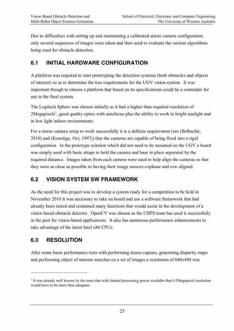
The camera calibration process requires the developer to present a checkerboard pattern to the imaging system at various angles of rotation and with edges angled towards and away from the cameras. Whilst this process may appear routine in practices it proved quite difficult to achieve accurate and consistent results. The following pictures show some calibration images using the checkerboard pattern.
Figure 6.1 Left and right images of one set of calibration images
Significant time was lost on this process which ultimately worked out to be a problem with OpenCV 2.0. Upgrading to OvenCV 2.1 made this process more reliable but the following does need to be considered to ensure good results:
Use a checkerboard that takes up as much of both camera image areas as possible. This may mean an A3 or A2 size sheet at an appropriate distance from the cameras.
Fix the checkerboard to a rigid flat surface.
Ensure that the boaexposed as possible, ie move to corners, etc.
Vision Based Obstacle Detection and School of Electrical, Electronic and Computer Engineering Multi Robot Object Position Estimation The University of Western Australia
28
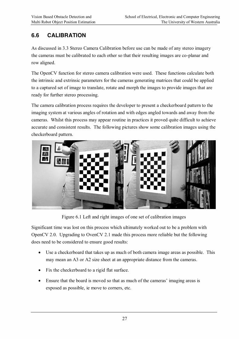
The following figures shows firstly the original captured images followed by two images from the left and right of the camera pair after they have been processed to make the images co-planar and row aligned.
Figure 6.2 Left and right original images
Note in Figure 6.2 how the images are offset horizontally and vertically.
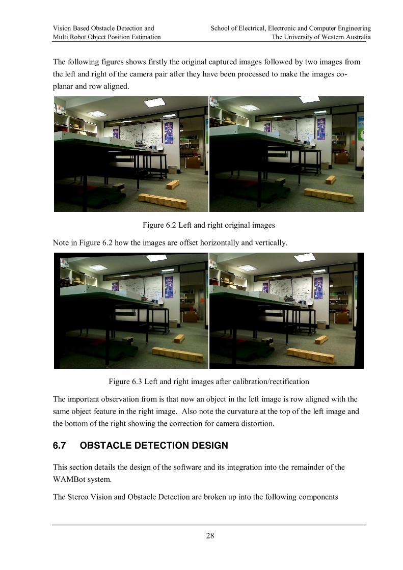
Figure 6.3 Left and right images after calibration/rectification
The important observation from is that now an object in the left image is row aligned with the same object feature in the right image. Also note the curvature at the top of the left image and the bottom of the right showing the correction for camera distortion.
6.7 OBSTACLE DETECTION DESIGN
This section details the design of the software and its integration into the remainder of the WAMBot system.
The Stereo Vision and Obstacle Detection are broken up into the following components
Vision Based Obstacle Detection and School of Electrical, Electronic and Computer Engineering Multi Robot Object Position Estimation The University of Western Australia
29
Vision Control
Image Pre-Processing
Obstacle Detection
Camera Calibration not shown.
The C++ language was chosen to develop this system as it is tightly coupled with the OpenCV library as well as being performance sensitive.
The following diagram shows how the obstacle detection is integrated into the WAMBot system as a whole.
Vision Based Obstacle Detection and School of Electrical, Electronic and Computer Engineering Multi Robot Object Position Estimation The University of Western Australia
30
«subsystem»ImageCapture (OpenCV)
StereoCameras
USB
RawStereoImages
RawStereoImages
ProcessedStereoImages
ProcessedStereoImages
ObstacleData
«subsystem»DataDistributionService
ExtrinsicIntrinsicParametersFile
ParameterData
«subsystem»Navigation
«subsystem»PathPlanner
ObstacleData
ObstacleData
Third Party
LegendStereo Vision
System
WAMBot System
«subsystem»OOIDetectionAndTrackingRawImages
VisionControl StereoImagePreProcessing
ObstacleDetection
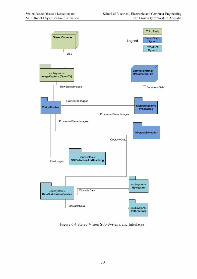
Figure 6.4 Stereo Vision Sub-Systems and Interfaces
Vision Based Obstacle Detection and School of Electrical, Electronic and Computer Engineering Multi Robot Object Position Estimation The University of Western Australia
31
6.7.1 Vision Control
This component is required to take raw captured images and pass them onto other systems for direct use or for further processing. It uses OpenCV to setup and read the image data from the stereo cameras.
This system must also listen to vehicle pose information being sent via DDS so that any movement of the UGV between when the images were taken and when the other WAMBot sus-systems use the obstacle information can be catered for.
6.7.2 Image Pre-Processing
This system takes the raw stereo images captured from the cameras and applies the required transforms for the intrinsic and extrinsic parameters of each camera to make the resulting images co-planar and row aligned. The transform parameters will be read from a configuration file generated during the camera calibration process.
The output of this system will be a pair of images that are suitable for generating a disparity map and for the application of other image processing techniques.
6.7.3 Obstacle Detection
Taking the pre-processed stereo images this system will apply the required algorithms to find obstacles in the scene that would not constitute a navigable path for the UGV. Using disparity data this system will determine the distance to the obstacle.
The output of this system will be a message containing data about the obstacles detected in the scene and their relative angle and distance from the UGV when the image was captured.
Finally, it will take the processed stereo image and apply obstacle detection algorithms passing on free space distance information through DDS to other WAMBot sub-systems.
6.7.4 Camera Calibration
This is a separate application run once to generate the intrinsic and extrinsic parameter file used by the Image Pre-Processing system. It uses multiple snapshots of a checkerboard taken at various angles and orientations. This data is then processed passed onto an OpenCV routine to determine the unknown parameters.
This system uses the same OpenCV image capture functions as the Vision Control system.
The output of the calibration is the previously mentioned parameters data file that is read in by the Image Pre-Processor.
Vision Based Obstacle Detection and School of Electrical, Electronic and Computer Engineering Multi Robot Object Position Estimation The University of Western Australia
32
6.8 IMPLENTED OPTIONS
What is required from obstacle detection is the ability to find a clear path in front of the UGV. As previous discussed in Chapter 2. Background and Options there are various options available to solving this problem each with its own advantages and disadvantages.
6.8.1 Colour and Texture M atching
This technique relies on the assumption that all the navigable ground is a similar colour and texture to that of the ground that it only requires a single image to perform the required processing.
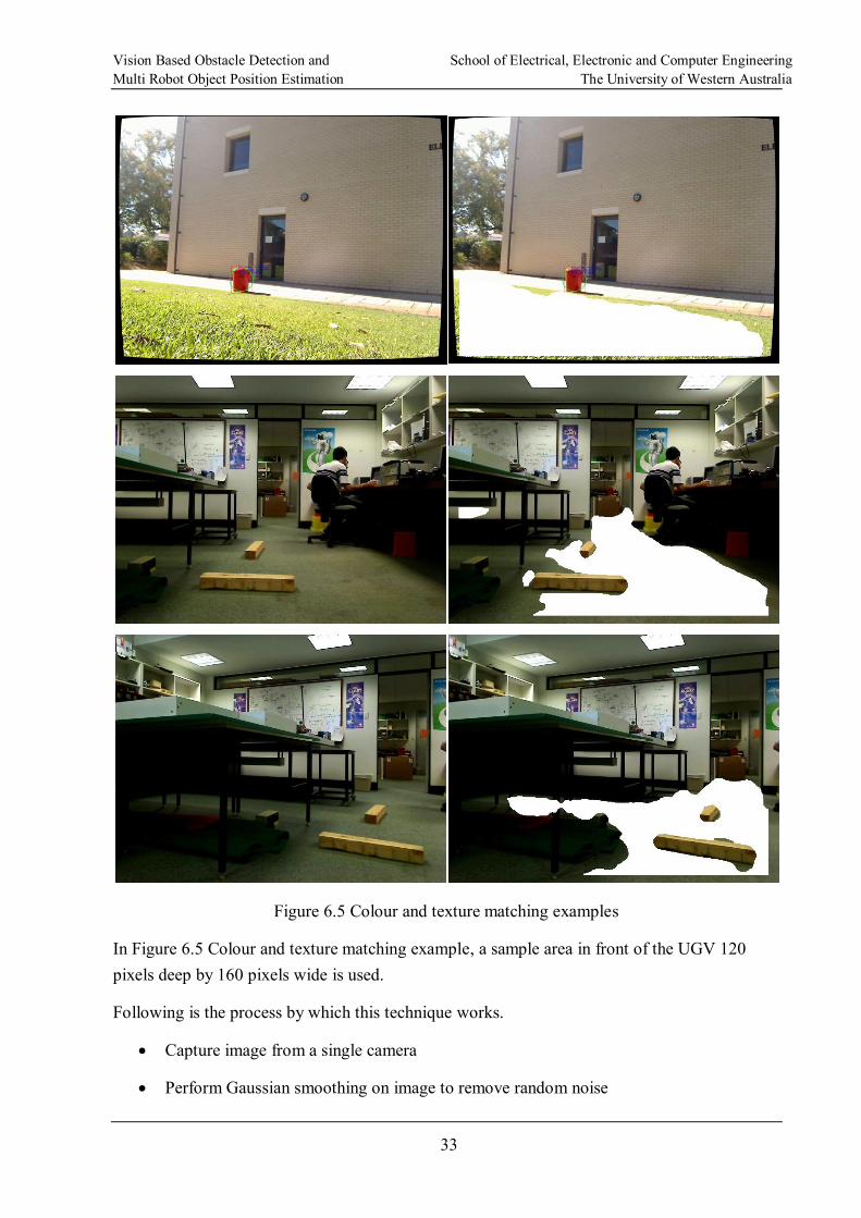
In Figure 6.5 the image on the left is the original and the right shows the navigable area shaded in white. This method works well except for the small patch of wall that is picked up in the middle set of images.
Vision Based Obstacle Detection and School of Electrical, Electronic and Computer Engineering Multi Robot Object Position Estimation The University of Western Australia
33
Figure 6.5 Colour and texture matching examples
In Figure 6.5 Colour and texture matching example, a sample area in front of the UGV 120 pixels deep by 160 pixels wide is used.
Following is the process by which this technique works.
Capture image from a single camera
Perform Gaussian smoothing on image to remove random noise
Vision Based Obstacle Detection and School of Electrical, Electronic and Computer Engineering Multi Robot Object Position Estimation The University of Western Australia
34
Convert image to Hue, Saturation and Value from Red, Green and Blue generated by the camera.
Compute a 2D hue vs saturation matrix of the region in front of the UGV.
Normalise the histogram to values 0..1.
Use the cvCalcBackProjectPatch OpenCV function which uses a sliding window over the image to find areas that match (are close to) the given template. In this case the CV_COMP_INTERSECT algorithm was used which for each point in the image patch and template it sums the minimum at that point, thus obviously good matches will result in a high value at that point and poor matches a low value.
The major issue with this is that the ground must be evenly lit, not be littered with any debris (paper, etc) and of a consistent texture and colour. Also during trials of this algorithm it was found that the cvCalcBackProjectPatch function consumes a lot of CPU time which could only be reduced by reducing the template match area which resulted in a reduced performance of accurately finding clear space in front of the UGV.
Distance measurements could only be determined for a stereo vision configuration, although mono is only required to implement the algorithm. Distance would be required to make the output of this system useful to navigation parts of the UGV system.
For a UGV needing to navigate in an unstructured and unknown environment this solution, at least by itself, is not an option.
6.8.2 G round Plane Projection
This technique is based on the theory described in 3.4 Ground Plane Projection. Described here is how this theory was implanted to create a solution that would provide the localisation, navigation and path planning systems of the UGV with information about obstacles in the environment.
In 6.4 Baseline Distance, the justification for a baseline distance of 30cm was given and is used in the prototype system.
The height of the camera lenses was set at 59cm for the prototype system, justification for which was given in 6.5 Camera Height.
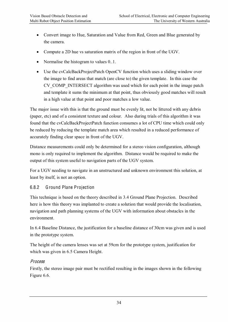
Process Firstly, the stereo image pair must be rectified resulting in the images shown in the following Figure 6.6.
Vision Based Obstacle Detection and School of Electrical, Electronic and Computer Engineering Multi Robot Object Position Estimation The University of Western Australia
35
Figure 6.6 Rectified left and right images
Next the left rectified image has the Canny edge detector applied to it. This step is required to reduce the search space for mismatches between the left projected image and the original right image by only searching around feature edges. The output of this process is shown in the following Figure 6.7.
Figure 6.7 Canny edge detector applied to images
Vision Based Obstacle Detection and School of Electrical, Electronic and Computer Engineering Multi Robot Object Position Estimation The University of Western Australia
36
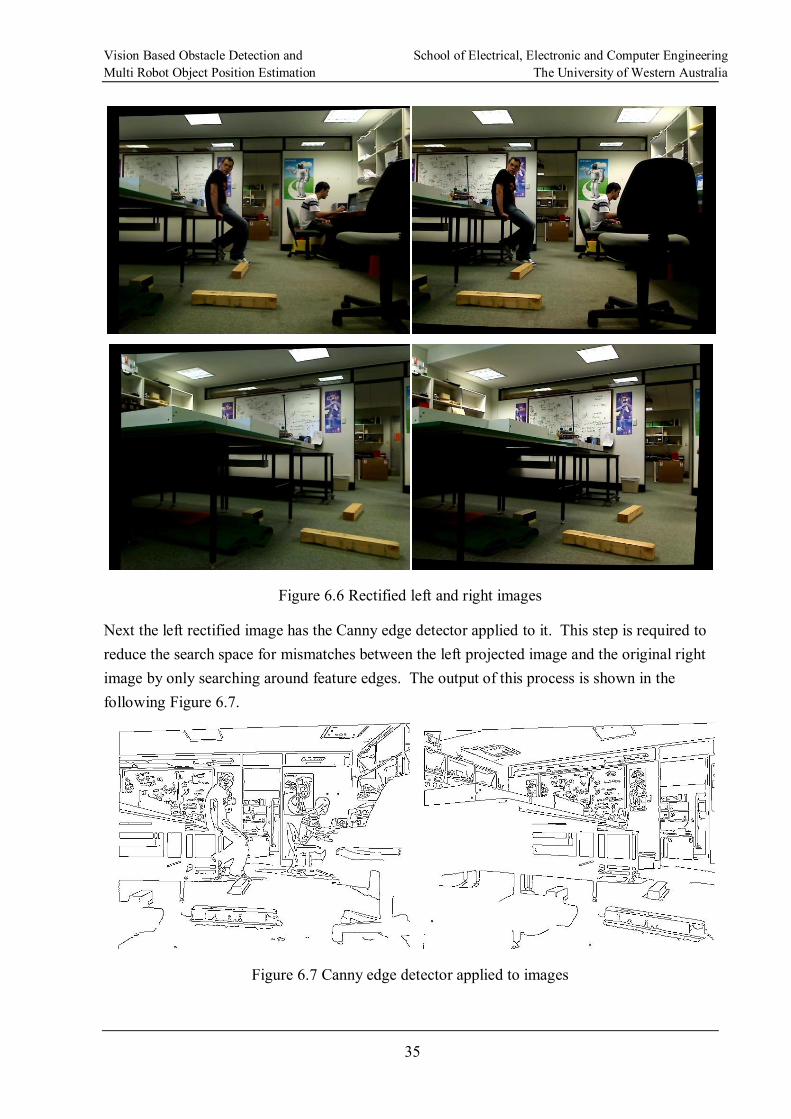
The Canny left image along with the original left image (converted to grey scale for block matching) are then projected onto the right image using the ground plane detection process described previously.
Figure 6.8 Ground Plane projection applied to left image
Using a least mean squares algorithm the projected left image is matched against the original right image. This matching is only performed at the edge of objects as found by the Canny detector. Following is the result of this show in Figure 6.9.

Vision Based Obstacle Detection and School of Electrical, Electronic and Computer Engineering Multi Robot Object Position Estimation The University of Western Australia
37
Figure 6.9 Highlighted areas indicate obstacles
At first glance it may appear that just the edges as originally found during edge detection have been picked out but it should be noted that for example in the left picture of Figure 6.9 the first wooden post is not marked as an obstacle although the edge detector did pick out features on it. Further examination into this problem of not picking out such items relates to the accuracy of actually having the cameras mounted perpendicular to the ground plane, this problem though is discussed later in 6.9 Improving the Results.
An important point of note from the above is that only obstacles sticking out of the ground plane have been considered since computations were not done for the upper half of the image. This scenario was acceptable for the WAMBot project as overhanging obstacles would not make up part of the challenge. With limited CPU resources the team does not want to waste time generating information that will never be used.
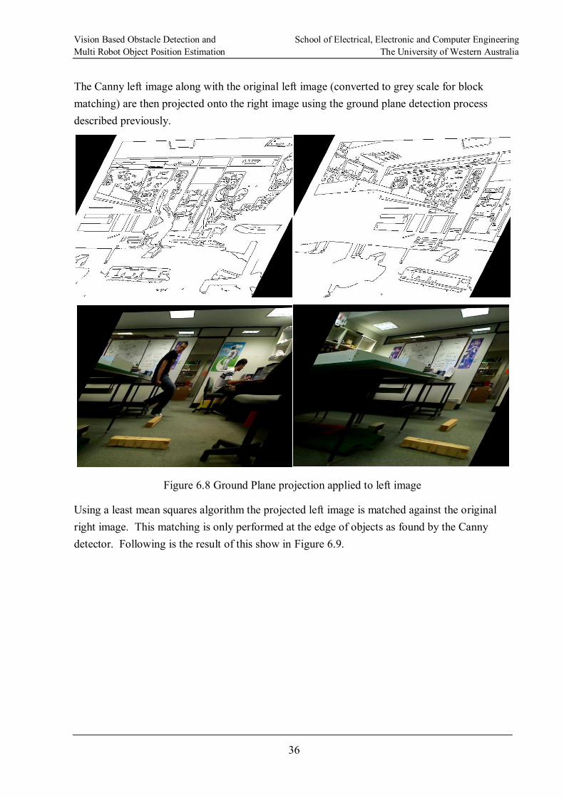
To know how far these obstacles are from the UGV it is next necessary to generate a disparity map by using one of the OpenCV block matching algorithms to find correspondence between the left and right rectified images. The stereo semi-global block matching algorithm was eventually used as it used half the CPU and generated better results than the stand stereo block matching algorithm. Again, the bottom half of the image was considered in line with the obstacle data generated with the results being shown in Figure 6.10. NOTE: The left image is the one with the person and the chair in the right foreground with the right image being the angled shot under the table.
Vision Based Obstacle Detection and School of Electrical, Electronic and Computer Engineering Multi Robot Object Position Estimation The University of Western Australia
38
Figure 6.10 Bottom half of disparity map for previous image pairs
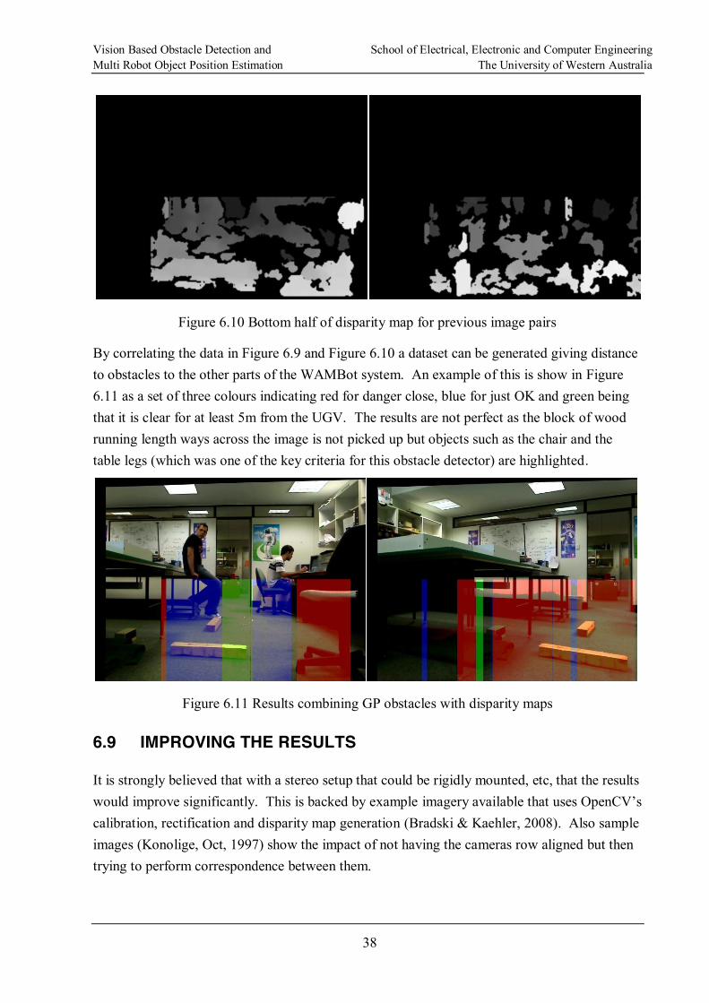
By correlating the data in Figure 6.9 and Figure 6.10 a dataset can be generated giving distance to obstacles to the other parts of the WAMBot system. An example of this is show in Figure 6.11 as a set of three colours indicating red for danger close, blue for just OK and green being that it is clear for at least 5m from the UGV. The results are not perfect as the block of wood running length ways across the image is not picked up but objects such as the chair and the table legs (which was one of the key criteria for this obstacle detector) are highlighted.
Figure 6.11 Results combining GP obstacles with disparity maps
6.9 IMPROVING THE RESULTS
It is strongly believed that with a stereo setup that could be rigidly mounted, etc, that the results would improve significantly. This is backed by example calibration, rectification and disparity map generation (Bradski & Kaehler, 2008). Also sample images (Konolige, Oct, 1997) show the impact of not having the cameras row aligned but then trying to perform correspondence between them.
Vision Based Obstacle Detection and School of Electrical, Electronic and Computer Engineering Multi Robot Object Position Estimation The University of Western Australia
39
One of the biggest problems with the ground plane projection technique is ensuring that the
but was not able to be fully prototyped where a relatively inexpensive laser scanner was mounted so that its beam points vertically out in front of the UGV. This information would be used to generate the correct projection (where it showed a flat plane or near flat plane in front of the UGV) matrix for the angle of the ground plane relative to the vehicle. Obvious merging of this data with what is found by the ground plane projection would be valuable as items such as the lump of wood in the left picture of Figure 6.9 Highlighted areas indicate obstacles would be detected.
An alternative is to model the ground plane based on the disparity map and then use RANSAC to model the uncertainty (Se & Brady, 2002).
Vision Based Obstacle Detection and School of Electrical, Electronic and Computer Engineering Multi Robot Object Position Estimation The University of Western Australia
40
CHAPTER 7. OBJECT LOCATION CORRELATION
For the WAMBot project, the goal required of object location correlation is to take position estimates for objects of interest, both static and mobile, from multiple UGVs and present a single unified picture to the operators on the GCS and to the other WAMBot systems that may require it for such tasks as navigation or neutralisation.
7.1 CORRELATOR DESIGN
The multi robot object position estimator or as it will be called in this text, Correlator, needs to work with many of the other WAMBot systems in order to both achieve its goals and to help achieve the goals of the system as a whole.
The correlator will need to use the Data Distribution Service as the bearer for the various messages that it must both receive and send.
The Java programming language was chosen for the development of this system. The
management features indicated this would result in a stable application. The correlator did need to perform many calculations but as its output was only near real time (updates were required to be sent out every second or two) and with a dedicated core available on the GCS, performance was not considered to be an issue. Finally DDS took care of the mapping of objects and data between the C/C++ and Java languages.
The overall goals of the OOI correlator were;
Fuse OOI position observations generated by one or more UGVs,
Manage the classification state of current set of correlated OOIs,
Present all correlated OOIs with a unique ID, and
Use DDS for receiving observations from UGVs and UAVs, receiving updates from the HMI and sending updates to the HMI.
7.1.1 Inputs
The correlator needs to accept the following inputs;
OOI Observation this is a message giving the pose of the UGV plus the angle and distance to the observed OOI. This observation message will also indicate whether the type of the object being observed is a static, mobile, non-combatant or unknown. Whilst the OOI Detection system is tracking an object OOI Observation messages will
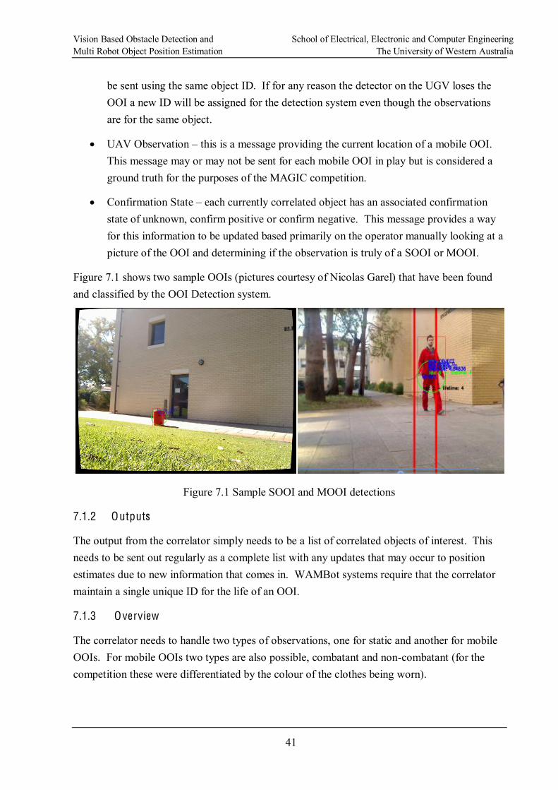
Vision Based Obstacle Detection and School of Electrical, Electronic and Computer Engineering Multi Robot Object Position Estimation The University of Western Australia
41
be sent using the same object ID. If for any reason the detector on the UGV loses the OOI a new ID will be assigned for the detection system even though the observations are for the same object.
UAV Observation this is a message providing the current location of a mobile OOI. This message may or may not be sent for each mobile OOI in play but is considered a ground truth for the purposes of the MAGIC competition.
Confirmation State each currently correlated object has an associated confirmation state of unknown, confirm positive or confirm negative. This message provides a way for this information to be updated based primarily on the operator manually looking at a picture of the OOI and determining if the observation is truly of a SOOI or MOOI.
Figure 7.1 shows two sample OOIs (pictures courtesy of Nicolas Garel) that have been found and classified by the OOI Detection system.
Figure 7.1 Sample SOOI and MOOI detections
7.1.2 Outputs
The output from the correlator simply needs to be a list of correlated objects of interest. This needs to be sent out regularly as a complete list with any updates that may occur to position estimates due to new information that comes in. WAMBot systems require that the correlator maintain a single unique ID for the life of an OOI.
7.1.3 Overview
The correlator needs to handle two types of observations, one for static and another for mobile OOIs. For mobile OOIs two types are also possible, combatant and non-combatant (for the competition these were differentiated by the colour of the clothes being worn).
Vision Based Obstacle Detection and School of Electrical, Electronic and Computer Engineering Multi Robot Object Position Estimation The University of Western Australia
42
When a UGV detects an OOI (via the OOI Detection system) it will assign that OOI a UUID and send out an OOI Observation message as described in 7.1.1. The OOI Detection system will continue to send out updated position information with the same UUID as long as the
track on the object is not lost. If the track is lost, the OOI Detection system will assign what it thinks is a new OOI a new UUID and continue to send out OOI Observation messages now using this new UUID for the tracked object. Simultaneously other UGVs will detect this or other OOIs and send out similar OOI Observation messages.
For static OOIs the correlator needs to maintain all observations referenced against the UGV OOI Detection system assigned UUID. Each one of the UGV UUIDs is assigned a correlator UUID so that a single UUID exists for each correlated object of interest. An expectation maximisation function is applied to the observed points1 to generate a centre and a major and minor axis radius (standard deviation or error). UGV assigned UUIDs are considered to be referencing the same OOI if their error bounds overlap or they are within 2.5m (see 7.1.4) of each other. If they are determined to be the same then the earliest correlator assigned UUID is maintained for both UGV UUIDs being merged and any new observation for either UGV UUID is automatically assigned to this merged correlator UUID. The correlator UUID also has associated with it a confirmation state. The initial value of this state is assigned the value given to the correlator by the OOI Observation system. A Confirmation State message with a correlator UUID can change this state to conf irmed positive or conf irmed negative. Any new observations that merge to this UUID will automatically pick up the updated confirmation state.
For mobile OOIs only the last two observations are maintained for any given UGV UUID and any new observation will update the correlated position by taking a weighted average of these last two and the most recent observation (Ferrein, Hermanns, & Lakemeyer, 2006). A correlated UUID is assigned to each UGV UUID as was done for the static case. A particular point of note here is that if an observation is not received that can be matched against any other received positions, the old positions will be timed out after 60 seconds as there is no guarantee as to where the MOOI will have moved to. The MOOIs were considered the same if they were within 2.5m (see 7.1.4) of each other. In addition to the observations generated by the UGVs observations were also received from a UAV feed. This information again was correlated with the currently known positions and correlated MOOIs were merged with the UAV feed by updating the current position estimate and setting their state to conf irmed positive.
1 A minimum of 3 observations are required on any particular UGV UUID before an EM is applied. This is to help remove noise from the total set of observations and to have enough data to apply the EM function.
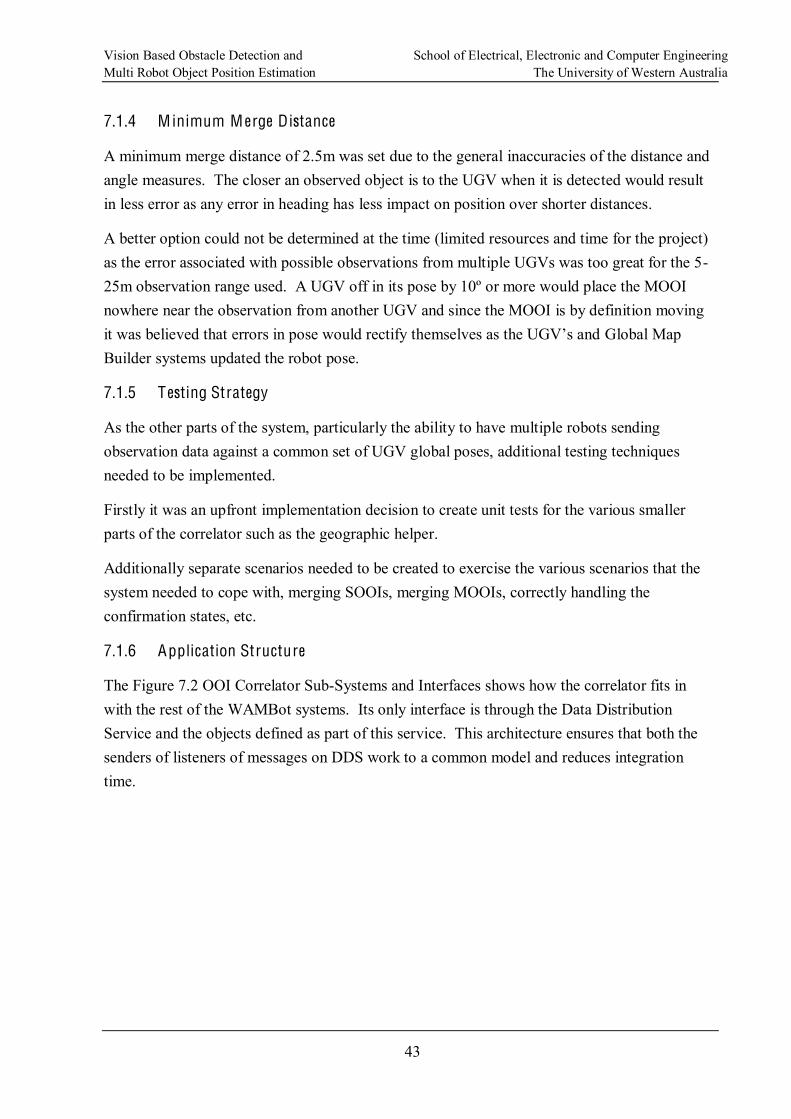
Vision Based Obstacle Detection and School of Electrical, Electronic and Computer Engineering Multi Robot Object Position Estimation The University of Western Australia
43
7.1.4 M inimum M erge Distance
A minimum merge distance of 2.5m was set due to the general inaccuracies of the distance and angle measures. The closer an observed object is to the UGV when it is detected would result in less error as any error in heading has less impact on position over shorter distances.
A better option could not be determined at the time (limited resources and time for the project) as the error associated with possible observations from multiple UGVs was too great for the 5-25m observation range used. A UGV off in its pose by 10º or more would place the MOOI nowhere near the observation from another UGV and since the MOOI is by definition moving
Global Map Builder systems updated the robot pose.
7.1.5 Testing Strategy
As the other parts of the system, particularly the ability to have multiple robots sending observation data against a common set of UGV global poses, additional testing techniques needed to be implemented.
Firstly it was an upfront implementation decision to create unit tests for the various smaller parts of the correlator such as the geographic helper.
Additionally separate scenarios needed to be created to exercise the various scenarios that the system needed to cope with, merging SOOIs, merging MOOIs, correctly handling the confirmation states, etc.
7.1.6 Application Structure
The Figure 7.2 OOI Correlator Sub-Systems and Interfaces shows how the correlator fits in with the rest of the WAMBot systems. Its only interface is through the Data Distribution Service and the objects defined as part of this service. This architecture ensures that both the senders of listeners of messages on DDS work to a common model and reduces integration time.
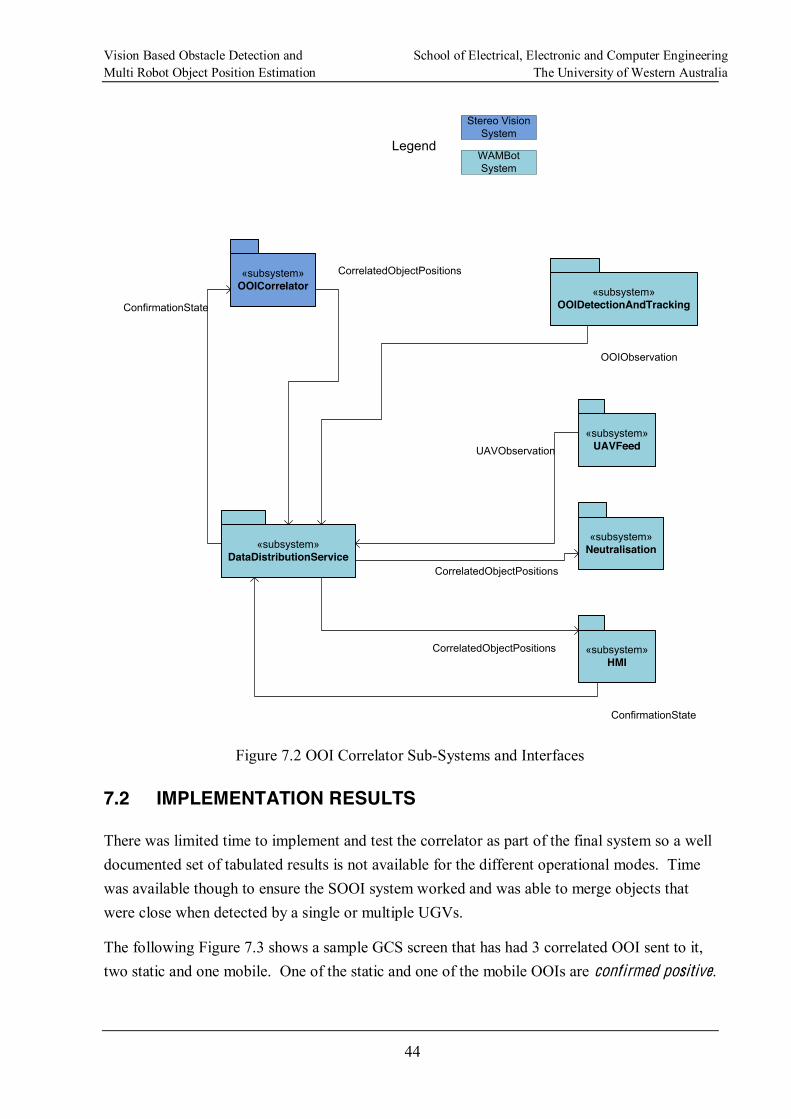
Vision Based Obstacle Detection and School of Electrical, Electronic and Computer Engineering Multi Robot Object Position Estimation The University of Western Australia
44
«subsystem»OOICorrelator
«subsystem»DataDistributionService
CorrelatedObjectPositions
«subsystem»Neutralisation
«subsystem»HMI
Legend
Stereo Vision System
WAMBot System
«subsystem»OOIDetectionAndTracking
OOIObservation
«subsystem»UAVFeedUAVObservation
CorrelatedObjectPositions
CorrelatedObjectPositions
ConfirmationState
ConfirmationState
Figure 7.2 OOI Correlator Sub-Systems and Interfaces
7.2 IMPLEMENTATION RESULTS
There was limited time to implement and test the correlator as part of the final system so a well documented set of tabulated results is not available for the different operational modes. Time was available though to ensure the SOOI system worked and was able to merge objects that were close when detected by a single or multiple UGVs.
The following Figure 7.3 shows a sample GCS screen that has had 3 correlated OOI sent to it, two static and one mobile. One of the static and one of the mobile OOIs are conf irmed positive.
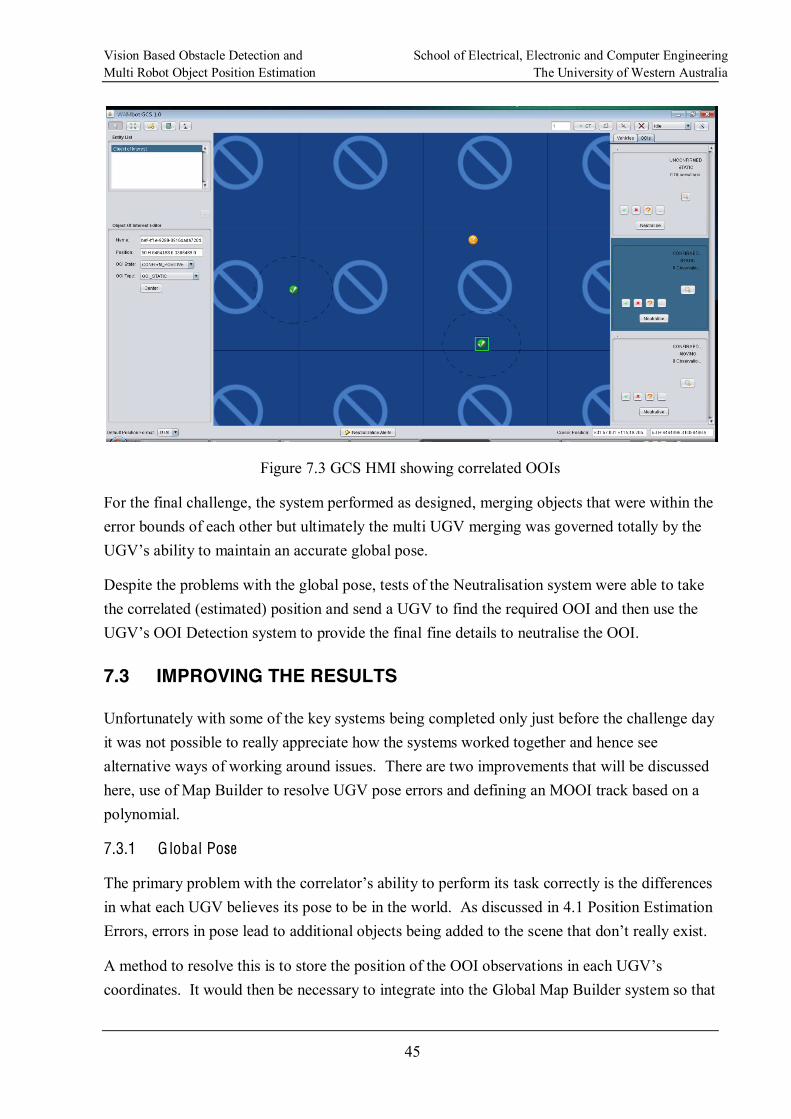
Vision Based Obstacle Detection and School of Electrical, Electronic and Computer Engineering Multi Robot Object Position Estimation The University of Western Australia
45
Figure 7.3 GCS HMI showing correlated OOIs
For the final challenge, the system performed as designed, merging objects that were within the error bounds of each other but ultimately the multi UGV merging was governed totally by the
ntain an accurate global pose.
Despite the problems with the global pose, tests of the Neutralisation system were able to take the correlated (estimated) position and send a UGV to find the required OOI and then use the
fine details to neutralise the OOI.
7.3 IMPROVING THE RESULTS
Unfortunately with some of the key systems being completed only just before the challenge day it was not possible to really appreciate how the systems worked together and hence see alternative ways of working around issues. There are two improvements that will be discussed here, use of Map Builder to resolve UGV pose errors and defining an MOOI track based on a polynomial.
7.3.1 Global Pose
task correctly is the differences in what each UGV believes its pose to be in the world. As discussed in 4.1 Position Estimation Errors, errors in pose lead to additional objects being added to the s
coordinates. It would then be necessary to integrate into the Global Map Builder system so that
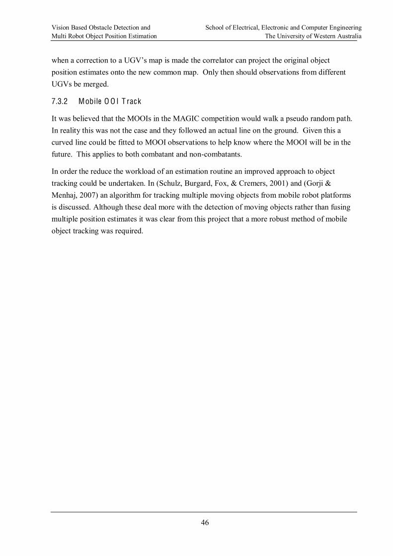
Vision Based Obstacle Detection and School of Electrical, Electronic and Computer Engineering Multi Robot Object Position Estimation The University of Western Australia
46
the correlator can project the original object position estimates onto the new common map. Only then should observations from different UGVs be merged.
7.3.2 Mobile O O I T rack
It was believed that the MOOIs in the MAGIC competition would walk a pseudo random path. In reality this was not the case and they followed an actual line on the ground. Given this a curved line could be fitted to MOOI observations to help know where the MOOI will be in the future. This applies to both combatant and non-combatants.
In order the reduce the workload of an estimation routine an improved approach to object tracking could be undertaken. In (Schulz, Burgard, Fox, & Cremers, 2001) and (Gorji & Menhaj, 2007) an algorithm for tracking multiple moving objects from mobile robot platforms is discussed. Although these deal more with the detection of moving objects rather than fusing multiple position estimates it was clear from this project that a more robust method of mobile object tracking was required.
Vision Based Obstacle Detection and School of Electrical, Electronic and Computer Engineering Multi Robot Object Position Estimation The University of Western Australia
47
CHAPTER 8. CONCLUSIONS
The aim of the work for this thesis was to develop obstacle avoidance and object position estimation systems for the entrant, WAMBot, in the MAGIC 2010 competition.
Presented has been a discussion of the theory, options and two implementations of vision based obstacle detection techniques. It was shown how the use of histogram colour matching can be used to find free space for the UGV to navigate through. Also presented was a method using a stereo vision based ground plane projection to find obstacles above and below the ground plane. The results presented are not perfect and this is to be expected as others in the field (Rankin, Huertas, & Matthies, 2005) use many different techniques to detect different classes of obstacle in the environment. Unfortunately, due to project budget constraints, this solution could not be further developed as part of the final UGV solution. Several improvements, in particular more accurately estimating the ground plane should be used in future development.
Also discussed were methods to the problem of multi robot object position estimation. The results in the final system were good for the given implementation for single UGVs in correlating both static and mobile objects of interest as long as the detection system primarily detected objects that fitted the given criteria. For multiple robots the solution only performed acceptably when there was close agreement between the UGVs on their global pose. Improvements including integration with the Global Map Builder should be considered for future development to resolve issues with global pose, as well as estimating the MOOI movement as a polynomial since the MOOIs followed a fixed path.
As a closing note, the WAMBot entrant came fourth in the November finals of MAGIC 2010,
Vision Based Obstacle Detection and School of Electrical, Electronic and Computer Engineering Multi Robot Object Position Estimation The University of Western Australia
48
APPENDIX A. BIBLIOGRAPHY
Belbachir, A. N. (2010). Smart Cameras. Springer US.
Bilmes, J. A. (1998). A Gentle Tutorial of the EM Algorithm. International Computer Science Institute. Berkeley CA.
Birchfield, S., & Tomasi, C. (1998). Depth discontinuities by pixel-to-pixel stereo. Sixth International Conference on Computer Vision, (pp. 1073-1080). Bombay.
Birchfield, S., & Tomasi, C. (1999). Depth Discontinuities by Pixel-to-Pixel Stereo. International Journal of Computer Vision , 35 (3), 269-293.
Bradski, G., & Kaehler, A. (2008). Learning OpenCV, Computer Vision with the OpenCV Library. New York: O'Reilly Media.
Chang, C., Chatterjee, S., & Kube, P. (1991). On an Analysis of Static Occlusion in Stereo Vision. Proceedings of Computer Vision and Pattern Recognition, (pp. 722-723).
Davies, E. R. (2005). Machine Vison, Theory, Algorithms, Practicalities. San Francisco: Denise E.M. Penrose.
Discant, A., Rogozan, A., Rusu, C., & Bensrhair, A. (2007). Sensors for Obstacle Detection - A Survey. Electronics Technology, 30th International Spring Seminar on, (pp. 100-105). Cluj-Napoca .
DSTO. (2010). MAGIC 2010 December Information Pack. Retrieved Novermber 18, 2010, from Defence Science and Technology Organisation: http://www.dsto.defence.gov.au/attachments/MAGIC2010-DecemberInformationPackage-Final.pdf
DSTO, D. S. (2010, November 13). DSTO Events MAGIC 2010 Super-smart robots wanted for international challenge. Retrieved November 19, 2010, from Defence Science and Technology Organisation (DSTO): http://www.dsto.defence.gov.au/MAGIC2010/
Ferrein, A., Hermanns, L., & Lakemeyer, G. (2006). Comparing Sensor Fusion Techniques for Ball Position Estimation. Robot Soccer World Cup IX , 154 165.
Froehlich, C., Mettenleiter, M., & Haertl, F. (1997). Active Laser Radar (LIDAR) for Measurement of Corresponding Height and Reflectance Images. Proceedings of SPIE , New Image Processing Techniques and Applications: Algorithms Methods, and Components II, 3101, pp. 292-305.
Vision Based Obstacle Detection and School of Electrical, Electronic and Computer Engineering Multi Robot Object Position Estimation The University of Western Australia
49
Gorji, A., & Menhaj, M. (2007). Multiple Target Tracking for Mobile Robots Using the JPDFAF Algorithm. 19th IEEE International Conference on Tools with Artif icial Intelligence, (pp. 137-145).
Konolige, K. (Oct, 1997). Small Vision Systems: Hardware and Implementation. Proceedings of E ighth International Symposium Robotics Research.
Lee, J.-h., Lee, W.-h., & Jeong, D.-s. (2003). Object Tracking Method Using Back-projection of Multiple Color Histogram Models. Proceedings of the 2003 International Symposium on Circuits and Systems, 2, pp. 668-671.
Li, F., & Brady, M. (July, 1998). Modeling the Ground Plane Transformation for Real-Time Obstacle Detection. Computer Vision and Image Understanding , Vol. 71, No. 1, pp. 137 152.
Robust Histogram Comparison. IEEE TRANSACTIONS ON PATTERN ANALYSIS AND MACHINE INTELLIGENCE , 29 (5), pp. 840-853.
Mandelb -Time Stereo Processing, Obstacle Detection, and Terrain Estimation from Vehicle-Mounted Stereo Cameras. Proceeds of IEEE Workshop Applications of Computer Vision, (pp. 288-289).
May, J., Bird, J., & Sharkasi, A. (2008). Simplified Stereo-Vision for Automated Control. IEEE International Conference on Technologies for Practical Robot Applications, (pp. 31-35).
Pulford, G., & Logothetis, A. (1997). An expectation-Maximisation Tracker for Multiple Observations of a Single target in Clutter. Proceedings of the 36th IEEE Conference on Decision and Contro, 5, pp. 4997 - 5003.
QinetiQ North America, I. (2010). Unmanned Vehicles - Qinetiq-NA. Retrieved Novermber 30, 2010, from Systems Engineering, IT Solutions, Technology Development - QinetiQ North America: http://www.foster-miller.com/products-unmanned-systems.htm
Rankin, A., Huertas, A., & Matthies, L. (2005). Evaluation of Stereo Vision Obstacle Detection Algorithms for Off-Road. AUVSI Symp. on Unmanned Systems .
Schulz, D., Burgard, W., Fox, D., & Cremers, A. (2001). Tracking Multiple Moving Objects with a Mobile Robot. Proceedings of the 2001 IEEE Computer Society Conference on Computer Vision and Pattern Recognition, (pp. 1-371 - 1-377).
Se, S., & Brady, M. (2002). Ground Plane Estimation, Error Analysis and Applications. Robotics and Autonomous Systems , 39 (2), 59-71.
Vision Based Obstacle Detection and School of Electrical, Electronic and Computer Engineering Multi Robot Object Position Estimation The University of Western Australia
50
Stroupe, A., Martin, M., & Balch, T. (2001). Distributed Sensor Fusion for Object Position Estimation by Multi-Robot Systems. Proceedings of IEEE Conference Robotics and Automation, (pp. 1092 1098).
Ulrich, I., & Nourbakhsh, I. (July/August 2000). Appearance-Based Obstacle Detection with Monocular Color Vision. Proceedings of the AAAI National Conference on Artif icial Intelligence. Austin, TX.
Vogel, D. (2003). The Politics of Risk Regulation in Europe and the United States. The Yearbook of European Environmental Law , 3.
Zhang, C., & Wang, P. (2000). A new method of color image segmentation. Proceedings of the 15th ICPR, (pp. 617-620, Vol 3). Barcelona.
Zhangfan, C., & Rongbao, C. (2009). License Plate Location Method Based on Modified HSI Model of Color Image. The Ninth International Conference on Electronic Measurement & Instruments, (pp. 4-197 - 4-201).
Zhou, Y., & Chirikjian, G. (2003). Probabilistic Models of Dead-Reckoning Error in Nonholonomic Mobile Robots. Proceedings of IEEE International Conference on Robotics & Automation, 2, pp. 1594 - 1599. Taipai.
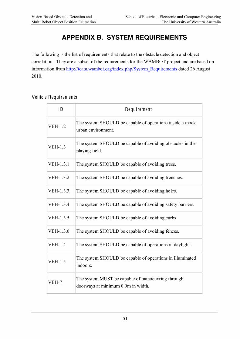
Vision Based Obstacle Detection and School of Electrical, Electronic and Computer Engineering Multi Robot Object Position Estimation The University of Western Australia
51
APPENDIX B. SYSTEM REQUIREMENTS
The following is the list of requirements that relate to the obstacle detection and object correlation. They are a subset of the requirements for the WAMBOT project and are based on information from http://team.wambot.org/index.php/System_Requirements dated 26 August 2010.
Vehicle Requi rements
ID Requirement
VEH-1.2 The system SHOULD be capable of operations inside a mock urban environment.
VEH-1.3 The system SHOULD be capable of avoiding obstacles in the playing field.
VEH-1.3.1 The system SHOULD be capable of avoiding trees.
VEH-1.3.2 The system SHOULD be capable of avoiding trenches.
VEH-1.3.3 The system SHOULD be capable of avoiding holes.
VEH-1.3.4 The system SHOULD be capable of avoiding safety barriers.
VEH-1.3.5 The system SHOULD be capable of avoiding curbs.
VEH-1.3.6 The system SHOULD be capable of avoiding fences.
VEH-1.4 The system SHOULD be capable of operations in daylight.
VEH-1.5 The system SHOULD be capable of operations in illuminated indoors.
VEH-7 The system MUST be capable of manoeuvring through doorways at minimum 0.9m in width.
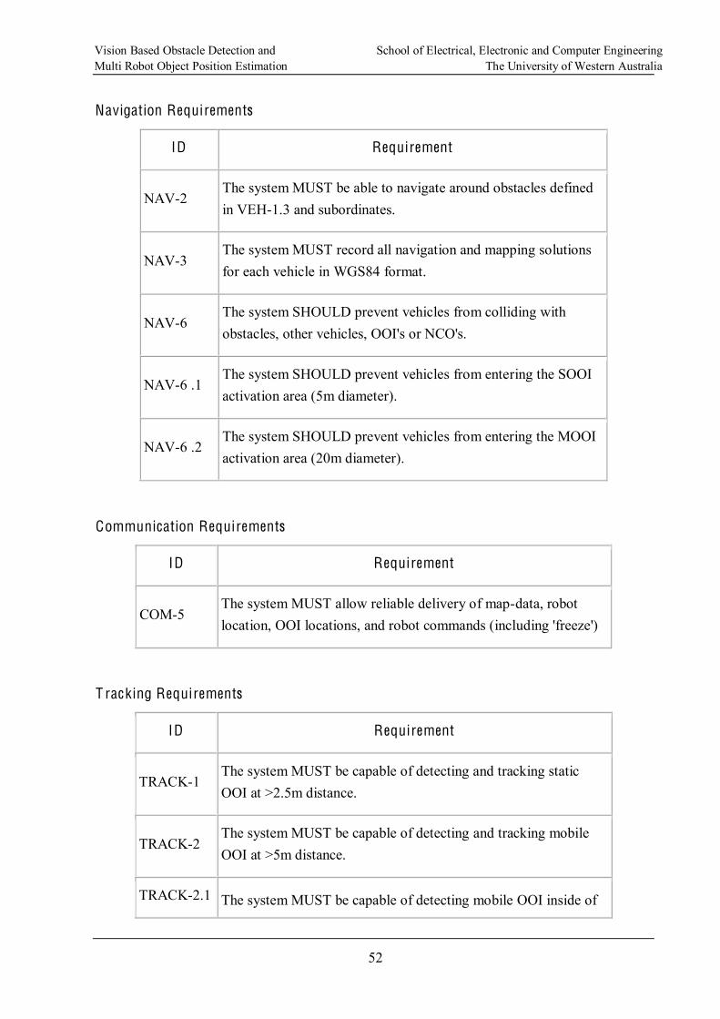
Vision Based Obstacle Detection and School of Electrical, Electronic and Computer Engineering Multi Robot Object Position Estimation The University of Western Australia
52
Navigation Requirements
ID Requirement
NAV-2 The system MUST be able to navigate around obstacles defined in VEH-1.3 and subordinates.
NAV-3 The system MUST record all navigation and mapping solutions for each vehicle in WGS84 format.
NAV-6 The system SHOULD prevent vehicles from colliding with obstacles, other vehicles, OOI's or NCO's.
NAV-6 .1 The system SHOULD prevent vehicles from entering the SOOI activation area (5m diameter).
NAV-6 .2 The system SHOULD prevent vehicles from entering the MOOI activation area (20m diameter).
Communication Requirements
ID Requirement
COM-5 The system MUST allow reliable delivery of map-data, robot location, OOI locations, and robot commands (including 'freeze')
T racking Requirements
ID Requirement
TRACK-1 The system MUST be capable of detecting and tracking static OOI at >2.5m distance.
TRACK-2 The system MUST be capable of detecting and tracking mobile OOI at >5m distance.
TRACK-2.1 The system MUST be capable of detecting mobile OOI inside of
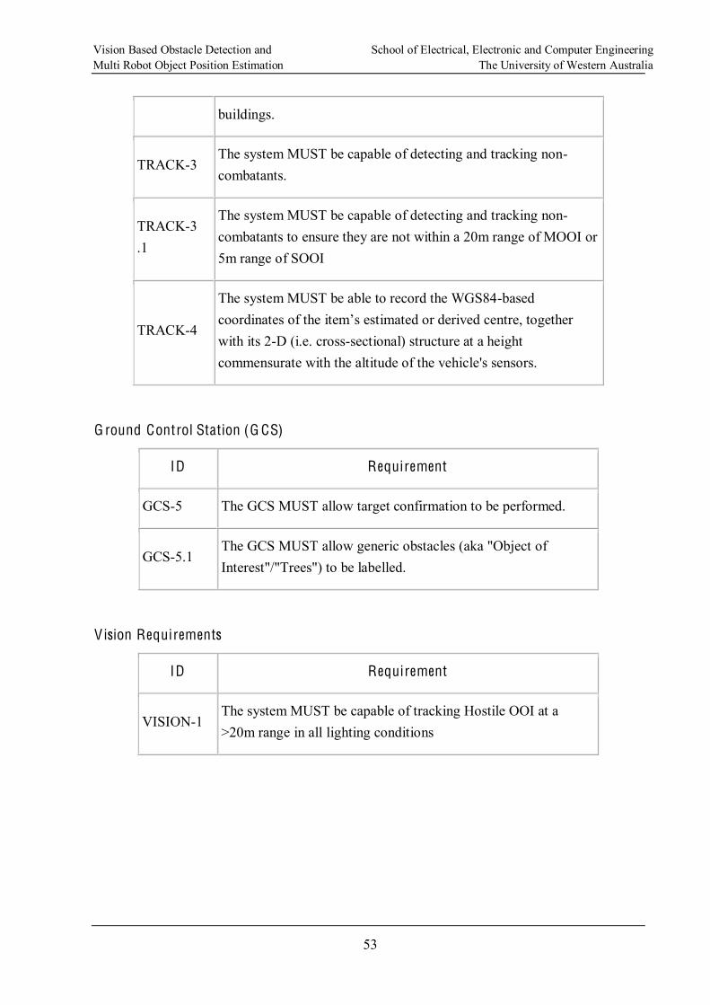
Vision Based Obstacle Detection and School of Electrical, Electronic and Computer Engineering Multi Robot Object Position Estimation The University of Western Australia
53
buildings.
TRACK-3 The system MUST be capable of detecting and tracking non-combatants.
TRACK-3 .1
The system MUST be capable of detecting and tracking non-combatants to ensure they are not within a 20m range of MOOI or 5m range of SOOI
TRACK-4
The system MUST be able to record the WGS84-based
with its 2-D (i.e. cross-sectional) structure at a height commensurate with the altitude of the vehicle's sensors.
G round Control Station (G CS)
ID Requirement
GCS-5 The GCS MUST allow target confirmation to be performed.
GCS-5.1 The GCS MUST allow generic obstacles (aka "Object of Interest"/"Trees") to be labelled.
V ision Requirements
ID Requirement
VISION-1 The system MUST be capable of tracking Hostile OOI at a >20m range in all lighting conditions
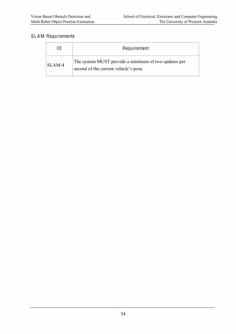
Vision Based Obstacle Detection and School of Electrical, Electronic and Computer Engineering Multi Robot Object Position Estimation The University of Western Australia
54
SL A M Requirements
ID Requirement
SLAM-4 The system MUST provide a minimum of two updates per
Vision Based Obstacle Detection and School of Electrical, Electronic and Computer Engineering Multi Robot Object Position Estimation The University of Western Australia
55
APPENDIX C. DISPARITY AND BASELINE VS DISTANCE
To use the disparity from a set of stereo images to calculate the distance to the object being observed it is necessary to know the focal length of the camera being used. Also as the disparity is not continuous due to the fact that it is based on discrete image sensor pixels a baseline must be chosen such that the required level of accuracy can be obtained.
This section provides details of the disparity versus distance for several baselines.
The following Table C.3 Disparity vs Distance for Different Baselines provides the distances that would be determines for various disparities. This information is generated for four different baselines to show the impact of the baseline on the granularity of the distances that can be measured.
The resolution chosen was 640x480 as any greater resolution was considered too high and would add considerably to the processing load of the system.
The focal length f was determined by the calibration of the Logitech Sphere camera and was part of the intrinsic matrix.
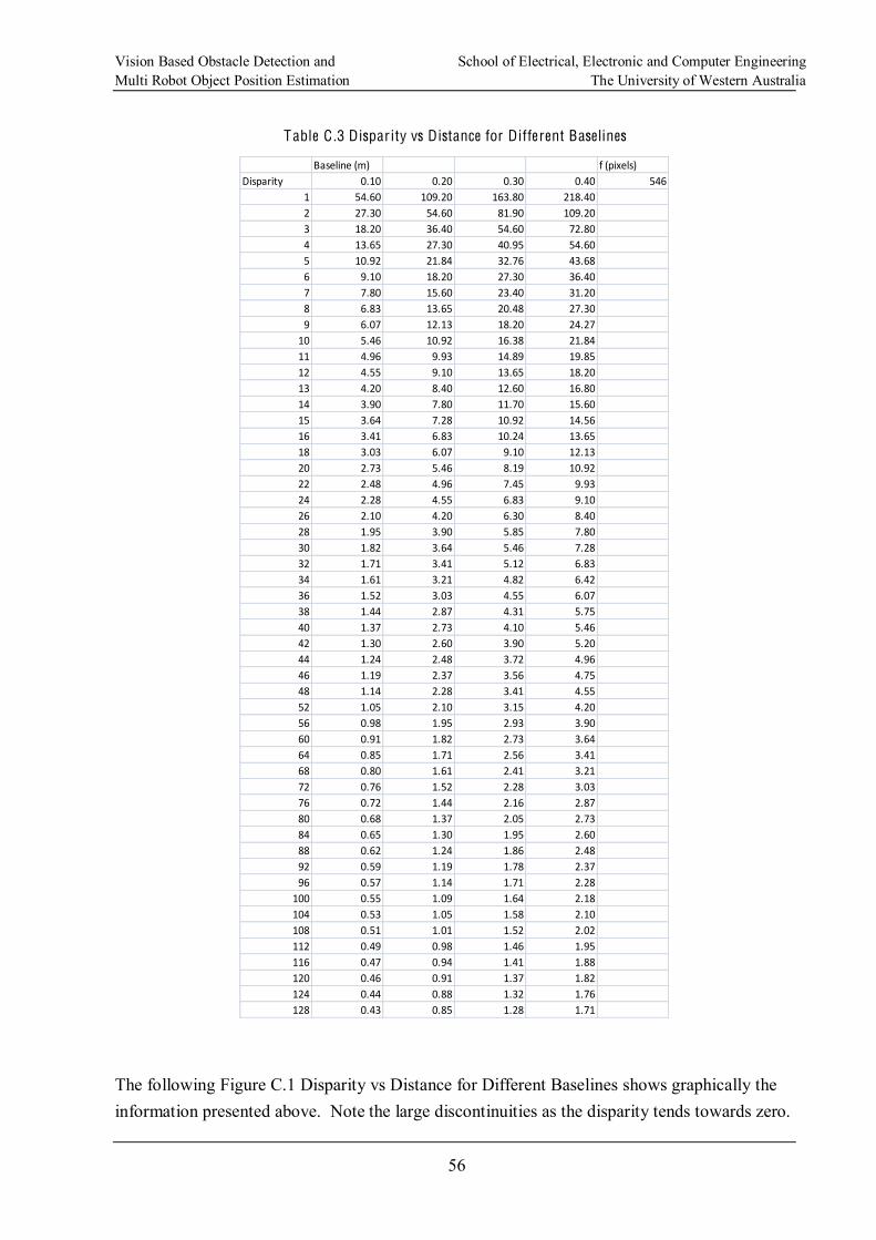
Vision Based Obstacle Detection and School of Electrical, Electronic and Computer Engineering Multi Robot Object Position Estimation The University of Western Australia
56
Table C .3 Disparity vs Distance for Different Baselines
Baseline (m) f (pixels)
Disparity 0.10 0.20 0.30 0.40 546
1 54.60 109.20 163.80 218.40
2 27.30 54.60 81.90 109.20
3 18.20 36.40 54.60 72.80
4 13.65 27.30 40.95 54.60
5 10.92 21.84 32.76 43.68
6 9.10 18.20 27.30 36.40
7 7.80 15.60 23.40 31.20
8 6.83 13.65 20.48 27.30
9 6.07 12.13 18.20 24.27
10 5.46 10.92 16.38 21.84
11 4.96 9.93 14.89 19.85
12 4.55 9.10 13.65 18.20
13 4.20 8.40 12.60 16.80
14 3.90 7.80 11.70 15.60
15 3.64 7.28 10.92 14.56
16 3.41 6.83 10.24 13.65
18 3.03 6.07 9.10 12.13
20 2.73 5.46 8.19 10.92
22 2.48 4.96 7.45 9.93
24 2.28 4.55 6.83 9.10
26 2.10 4.20 6.30 8.40
28 1.95 3.90 5.85 7.80
30 1.82 3.64 5.46 7.28
32 1.71 3.41 5.12 6.83
34 1.61 3.21 4.82 6.42
36 1.52 3.03 4.55 6.07
38 1.44 2.87 4.31 5.75
40 1.37 2.73 4.10 5.46
42 1.30 2.60 3.90 5.20
44 1.24 2.48 3.72 4.96
46 1.19 2.37 3.56 4.75
48 1.14 2.28 3.41 4.55
52 1.05 2.10 3.15 4.20
56 0.98 1.95 2.93 3.90
60 0.91 1.82 2.73 3.64
64 0.85 1.71 2.56 3.41
68 0.80 1.61 2.41 3.21
72 0.76 1.52 2.28 3.03
76 0.72 1.44 2.16 2.87
80 0.68 1.37 2.05 2.73
84 0.65 1.30 1.95 2.60
88 0.62 1.24 1.86 2.48
92 0.59 1.19 1.78 2.37
96 0.57 1.14 1.71 2.28
100 0.55 1.09 1.64 2.18
104 0.53 1.05 1.58 2.10
108 0.51 1.01 1.52 2.02
112 0.49 0.98 1.46 1.95
116 0.47 0.94 1.41 1.88
120 0.46 0.91 1.37 1.82
124 0.44 0.88 1.32 1.76
128 0.43 0.85 1.28 1.71
The following Figure C.1 Disparity vs Distance for Different Baselines shows graphically the information presented above. Note the large discontinuities as the disparity tends towards zero.
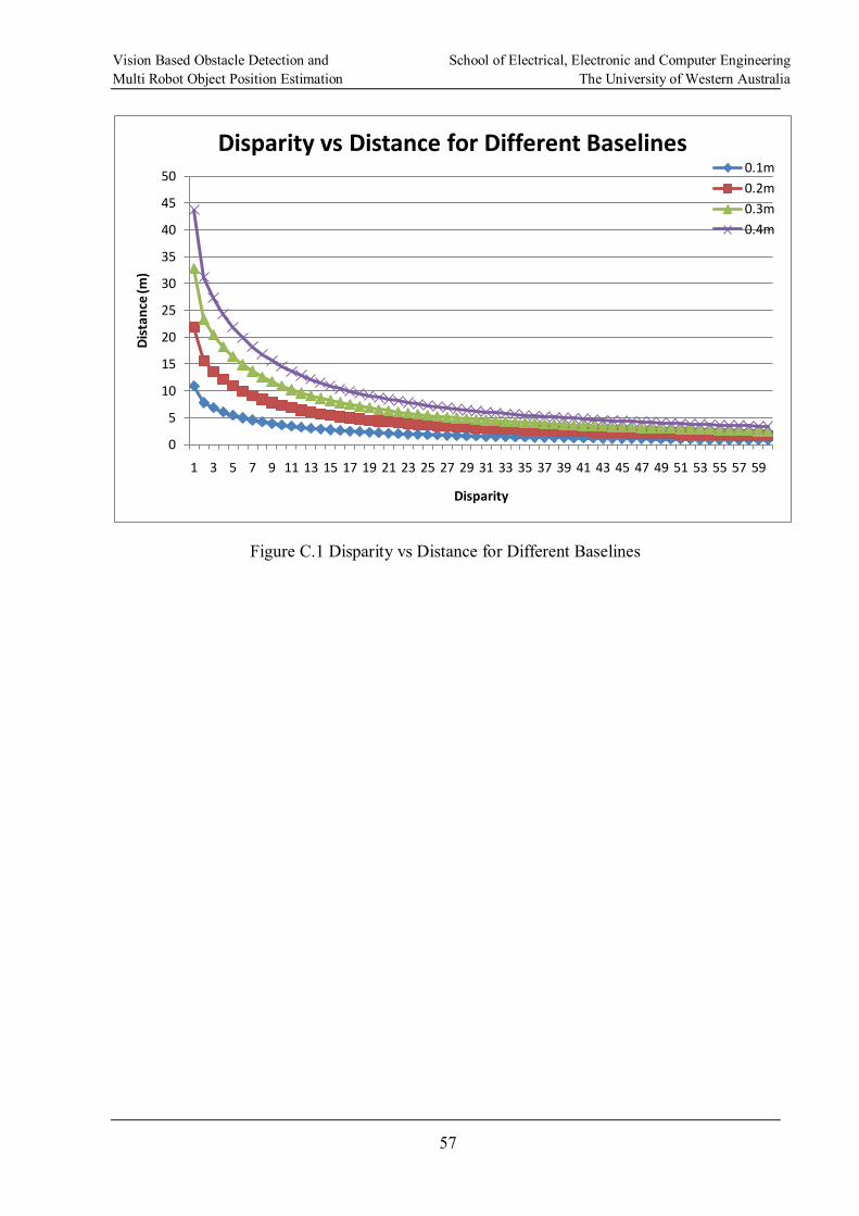
Vision Based Obstacle Detection and School of Electrical, Electronic and Computer Engineering Multi Robot Object Position Estimation The University of Western Australia
57
Figure C.1 Disparity vs Distance for Different Baselines
0
5
10
15
20
25
30
35
40
45
50
1 3 5 7 9 11 13 15 17 19 21 23 25 27 29 31 33 35 37 39 41 43 45 47 49 51 53 55 57 59
Distance (m
)
Disparity
Disparity vs Distance for Different Baselines0.1m
0.2m
0.3m
0.4m
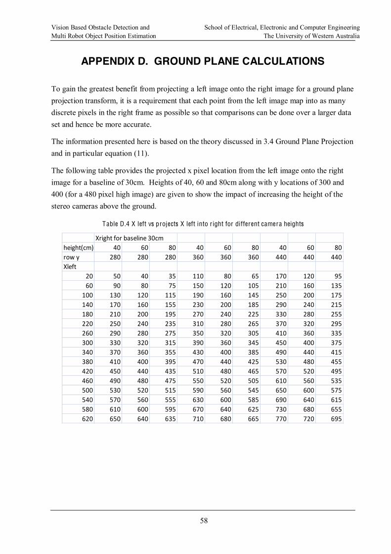
Vision Based Obstacle Detection and School of Electrical, Electronic and Computer Engineering Multi Robot Object Position Estimation The University of Western Australia
58
APPENDIX D. GROUND PLANE CALCULATIONS
To gain the greatest benefit from projecting a left image onto the right image for a ground plane projection transform, it is a requirement that each point from the left image map into as many discrete pixels in the right frame as possible so that comparisons can be done over a larger data set and hence be more accurate.
The information presented here is based on the theory discussed in 3.4 Ground Plane Projection and in particular equation (11).
The following table provides the projected x pixel location from the left image onto the right image for a baseline of 30cm. Heights of 40, 60 and 80cm along with y locations of 300 and 400 (for a 480 pixel high image) are given to show the impact of increasing the height of the stereo cameras above the ground.
Table D .4 X left vs projects X left into r ight for different camera heights
Xright for baseline 30cm
height(cm) 40 60 80 40 60 80 40 60 80
row y 280 280 280 360 360 360 440 440 440
Xleft
20 50 40 35 110 80 65 170 120 95
60 90 80 75 150 120 105 210 160 135
100 130 120 115 190 160 145 250 200 175
140 170 160 155 230 200 185 290 240 215
180 210 200 195 270 240 225 330 280 255
220 250 240 235 310 280 265 370 320 295
260 290 280 275 350 320 305 410 360 335
300 330 320 315 390 360 345 450 400 375
340 370 360 355 430 400 385 490 440 415
380 410 400 395 470 440 425 530 480 455
420 450 440 435 510 480 465 570 520 495
460 490 480 475 550 520 505 610 560 535
500 530 520 515 590 560 545 650 600 575
540 570 560 555 630 600 585 690 640 615
580 610 600 595 670 640 625 730 680 655
620 650 640 635 710 680 665 770 720 695