visible emissions program operations manual - us epa · visible emissions program operations manual...
TRANSCRIPT

Visible Emissions Program Operations Manual
U.S. ENVIRONMENTAL PROTECTION AGENCY REGION IV AIR SURVEILLANCE BRANCH SURVEILLANCE & ANALYSIS DIVISION ATHENS, GEORGIA 30601
_.

EPA-340/ l-79-009
February 1979
Visible Emissions Program Operational Manual
Victoria Scott
Pacific Environmental Services, Inc. 1930 14th Street
Santa Monica, California 90404
Contract No. 68-01-4140
Task No. 32
EPA Project Officer: John R. Busik
Task Manager: Tom Rose
Prepared for
U.S. ENWRONMENTAL PROTECTION AGENCY Region IV Air Surveillance Branch Surveillance 81 Analysis Division
Athens, Georgia 30601
__,_. , . _,.& --__. u I _ . . - . - . . . - . _ . - - _ . - - _ b . * . . . _ - I - I - . - . - . - _ . - _--__. _ . . . _ . . . . - . _ -__ ____ *-__ ._____ _ . - _ . . . _ . ______ --__-. -___-.___ ,_ _ . .
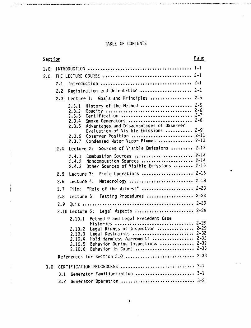
TABLE OF CONTENTS
Sect ion Page
1.0 INTRODUCTION .......................................... l-l
2.0 THE LECTURE COURSE .................................... 2-1
2.1 Introduction ..................................... 2-l
2.2 Registration and Orientation ..................... 2-l
2.3 Lecture 1: Goals and Principles ................. 2-5
2.3.1 History of the Method ..................... 2-5
2.3.2 Opacity ................................... 2-6 2.3.3 Certification ............................. 2-7 2.3.4 Smoke Generators .......................... 2-8 2.3.5 Advantages and Disadvantages of Observer
Evaluation of Visible Emissions ........... 2-9 2.3.6 Observer Position ......................... 2-11
2.3.7 Condensed Water Vapor Plumes .............. 2-13
2.4 Lecture 2: Sources of Visible Emissions ......... 2-13
2.4.1 Combustion Sources ........................ 2-14 2.4.2 Noncombustion Sources ..................... 2-14
2.4.3 Other Sources of Visible Emissions ........ 2-15
2.5 Lecture 3: Field Operations ..................... 2-15
2.6 Lecture 4: Meteorology .......................... 2-18
2.7 Film: "Role of the Witness" ..................... 2-23
2.8 Lecture 5: Testing Procedures ................... 2-23
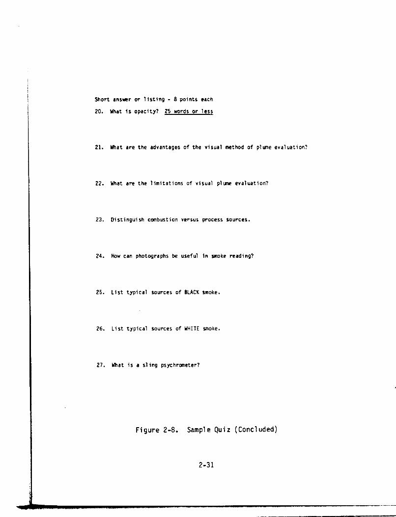
2.9 Quiz ............................................. 2-29
2.10 Lecture 6: Legal Aspects ........................ 2-29
2.10.1 Method 9 and Legal Precedent Case Histories ................................ 2-29
2.10.2 Legal Rights of Inspection ............... 2-29 2.10.3 Legal Restraints ......................... 2-32 2.10.4 Hold Harmless Agreements ................. 2-32 2.10.5 Behavior During Inspections .............. 2-32 2.10.6 Behavior in Court ........................ 2-33
References for Section 2.0 ............................ 2-33
3.0 CERTIFICATION PROCEDURES .............................. 3-l
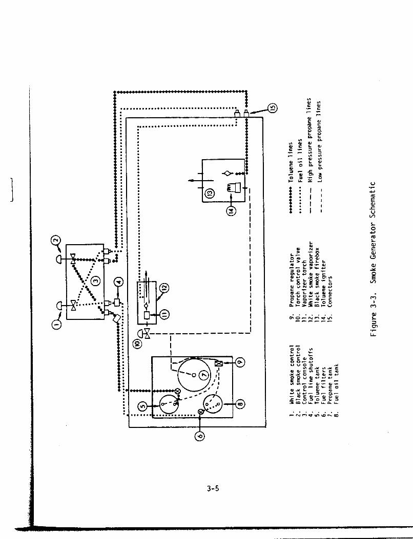
3.1 Generator Familiarization ........................ 3-l
3.2 Generator Operation .............................. 3-2
.
i

TABLE OF CONTENTS (Continued)
Section Page
3.3 Generator Calibration ............................ 3-6
3.3.1 Zero and Span Drift ....................... 3-6 3.3.2 Calibration Error ......................... 3-8
3.3.3 Calibration Procedures .................... 3-8
3.4 Practice Sessions ................................ 3-9
3.5 Training Sessions ................................ 3-14
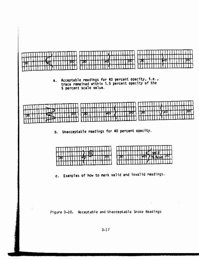
3.6 Testing Procedures . . . . . . . . . . . . . . . . . . . . . . . . . . . . . . . 3-18
3.7 Generator Shutdown . . . . . . . . . . . . . . . . . . . . . . . . . . . . . . . 3-19
3.8 Maintenance Procedures . . . . . . . . . . . . . . . . . . . . . . . . . . . 3-22
3.9 Recordkeeping .................................... 3-23
3.10 Recertification Procedures ....................... 3-24
References for Section 3.0 . . . . . . . . . . . . . . . . . . . . . . . . . . . . 3-24
4.0 DATA REDUCTION ........................................ 4-l
4.1 Grading the Certification Form ................... 4-1
4.2 Certification Letters ............................ 4-3
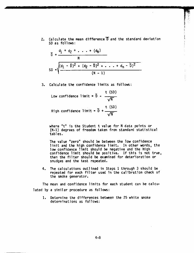
4.3 Mean Deviation and Confidence Limits .............. 4-6
References for Section 4.0 ............................ 4-10
APPENDIX A.
APPENDIX B.
APPENDIX C.
APPENDIX D.
APPENDIX E.
APPENDIX F.
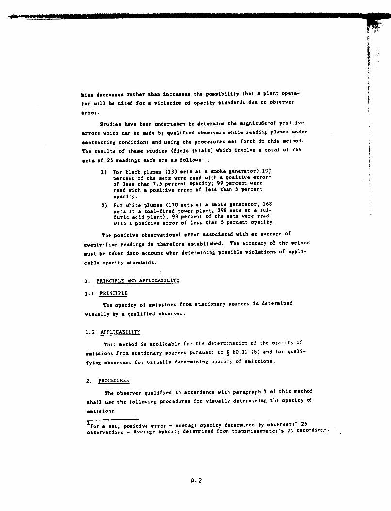
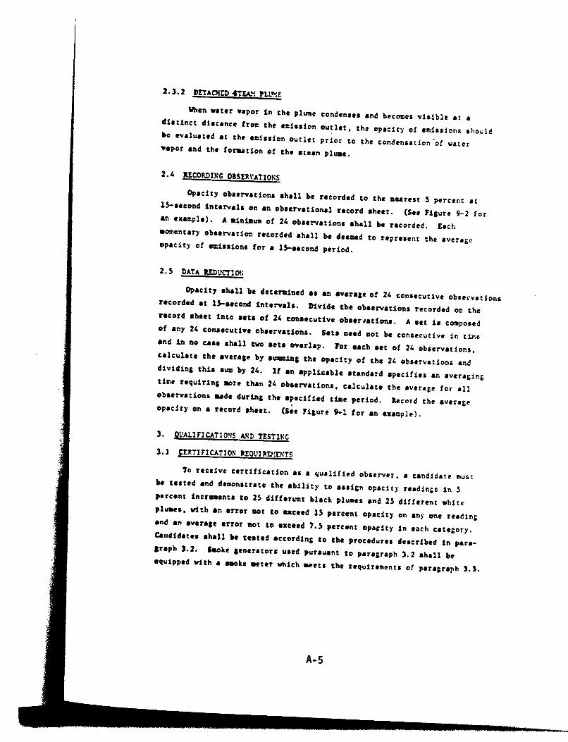
METHOD 9 ...................................... A-l
CAMERA INSTRUCT IONS ........................... B-l
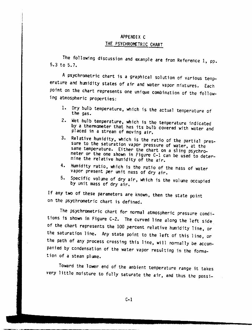
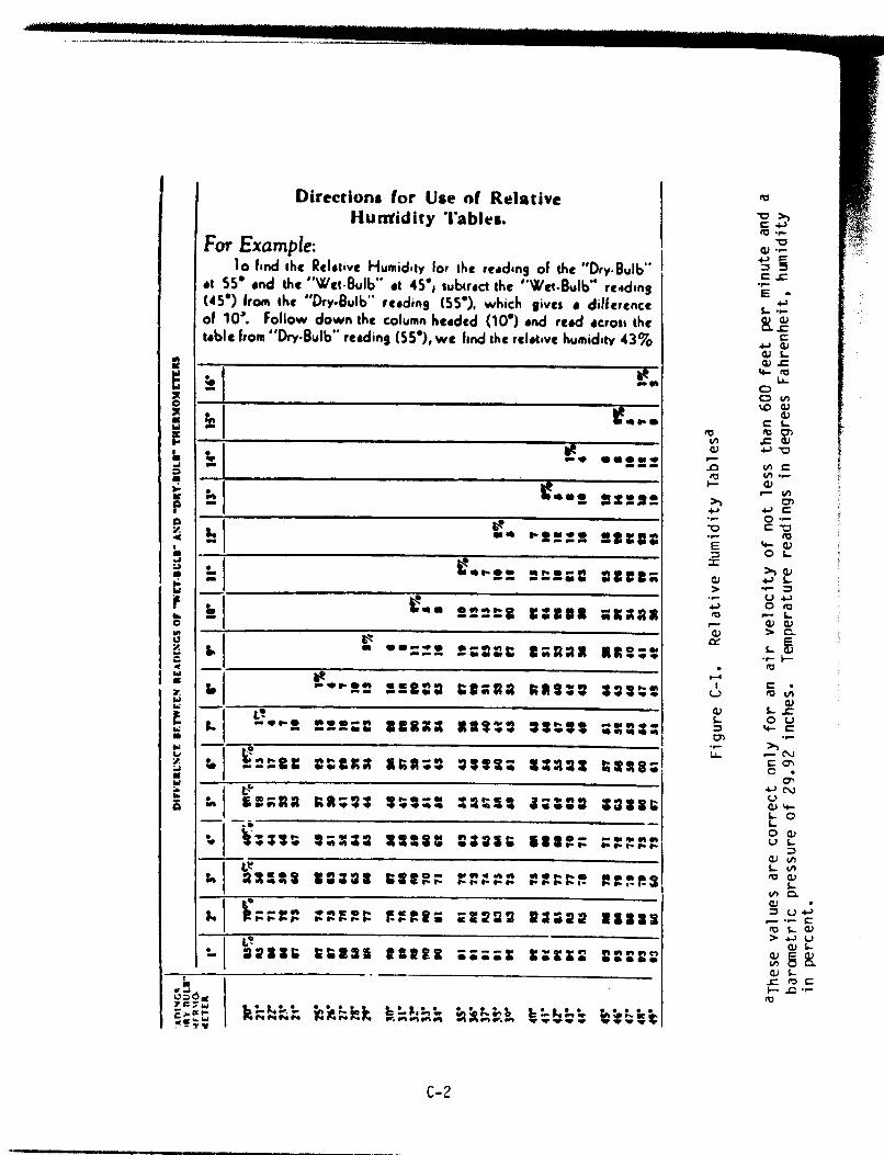
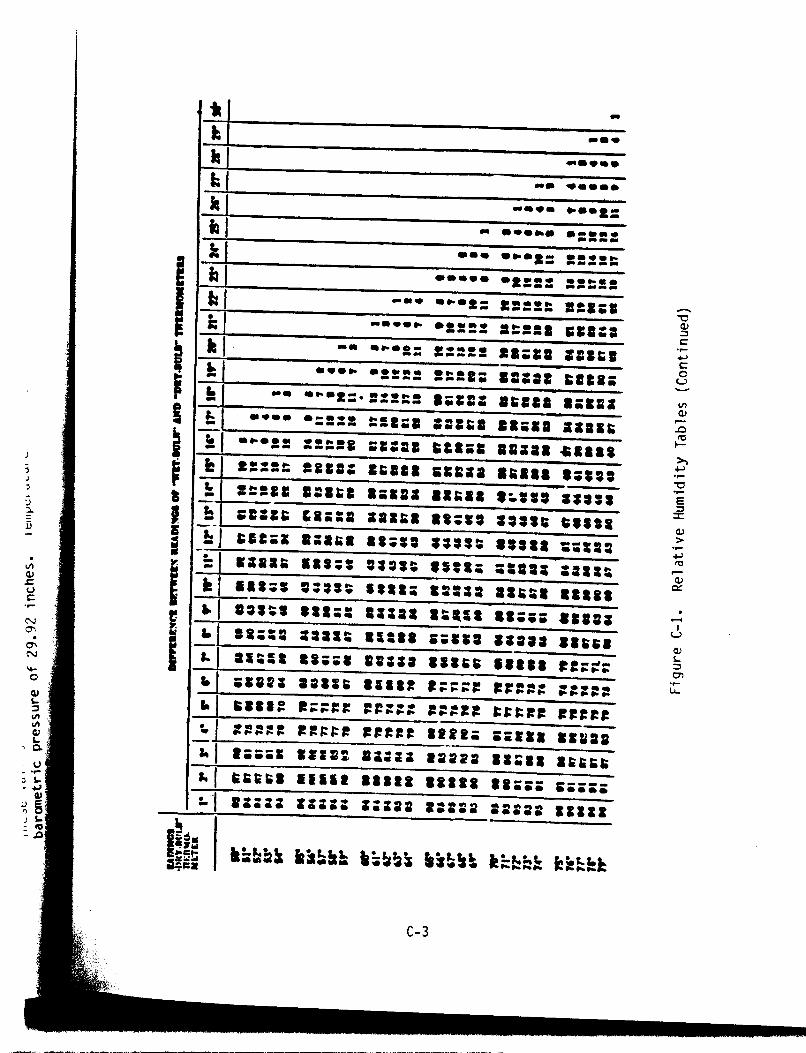
THE PSYCHROMETRIC CHART ....................... C-l
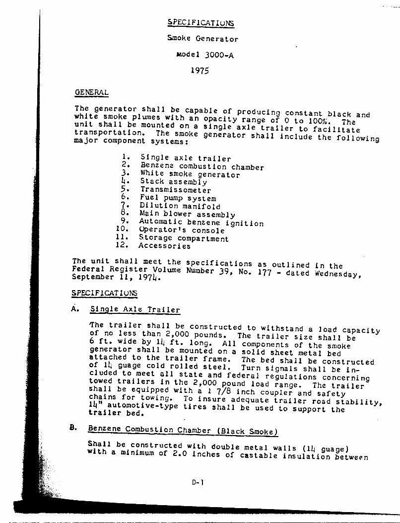
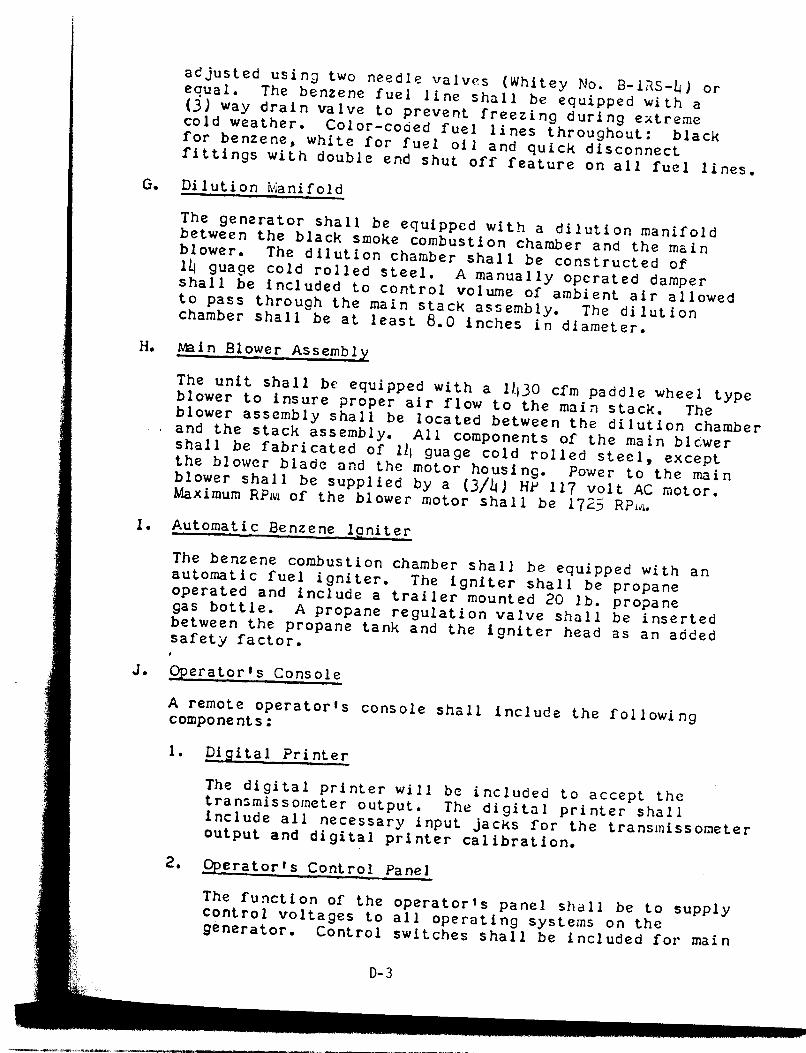
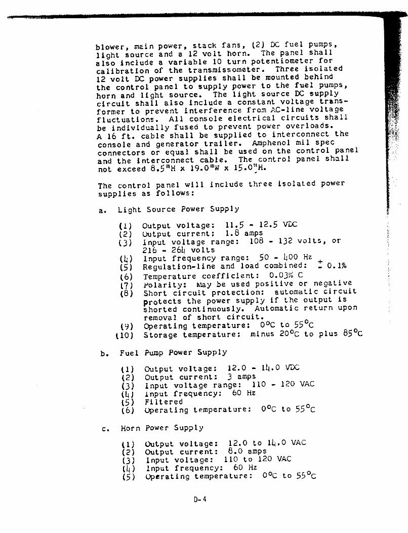
SMOKE GENERATOR SPECIFICATIONS, MODEL 3000-A . . D-l
OPERATOR'S MANUAL, MODEL 3000 SMOKE GENERATOR ..................................... E-l
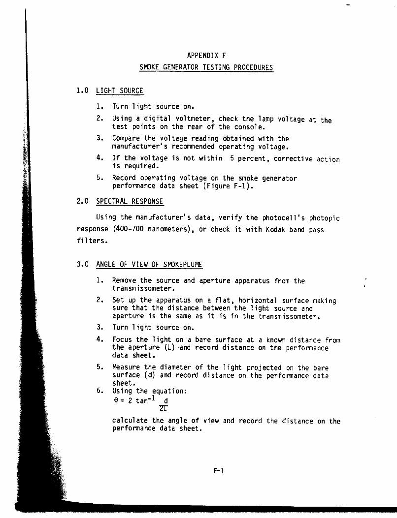
SMOKE GENERATOR TESTING PROCEDURES ............ F-l
1.0 Light Source ..................................... F-l
2.0 Spectral Response ................................ F-l
,__ . ._ - _ - - . _ . . . . . . - . . . . .a ,1_-_- - _...__eI_m . - - - - . - . . - - . - - - - - - - - - - - - - _. . . - . - . _ - . . . . _ . . . . I _ _ . - _. - . - . ____ .._L - _ - - - . . . . . . . -
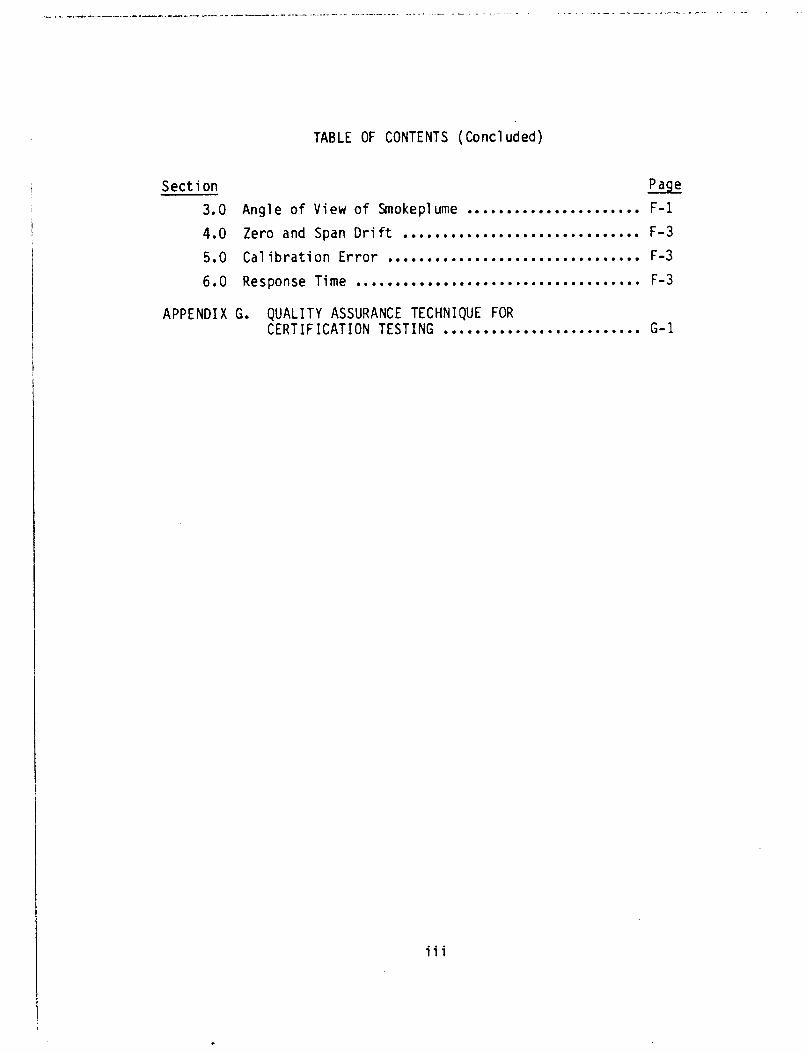
TABLE OF CONTENTS (Concluded)
Section Paqe
3.0 Angle of View of Smokeplume ...................... F-l
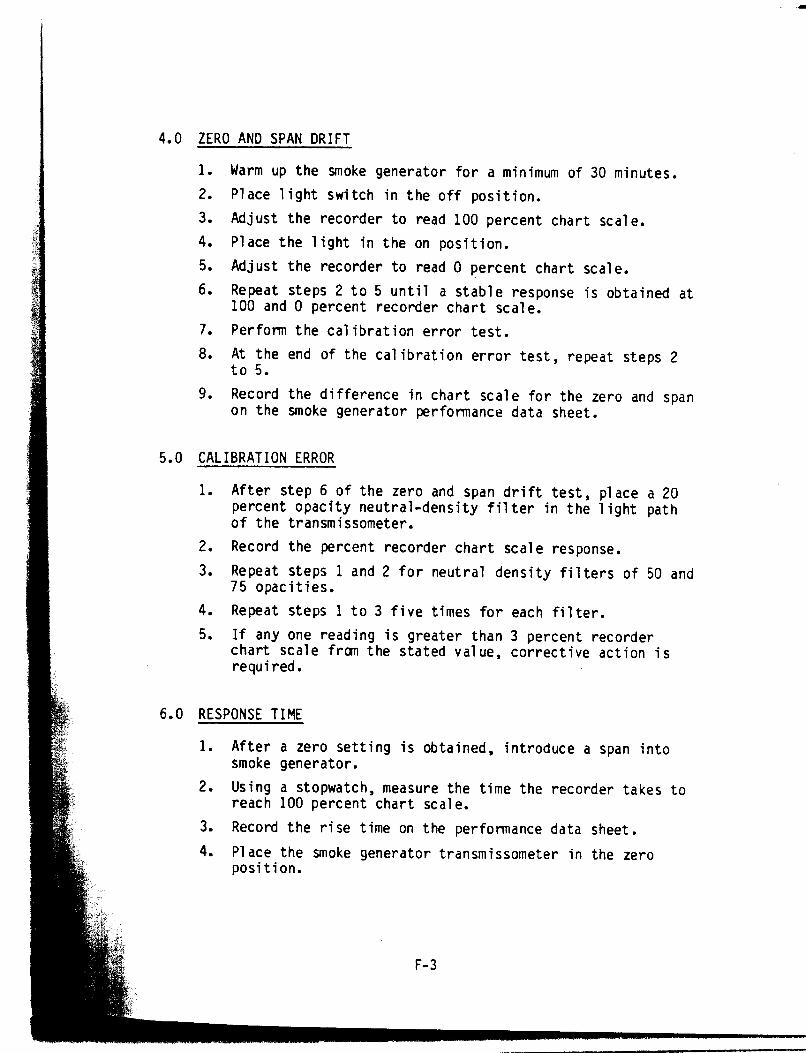
4.0 Zero and Span Drift .............................. F-3
5.0 Calibration Error ................................ F-3
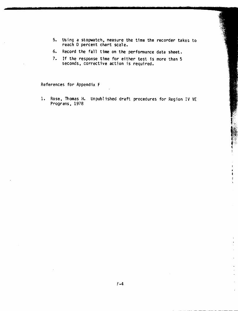
6.0 Response Time .................................... F-3
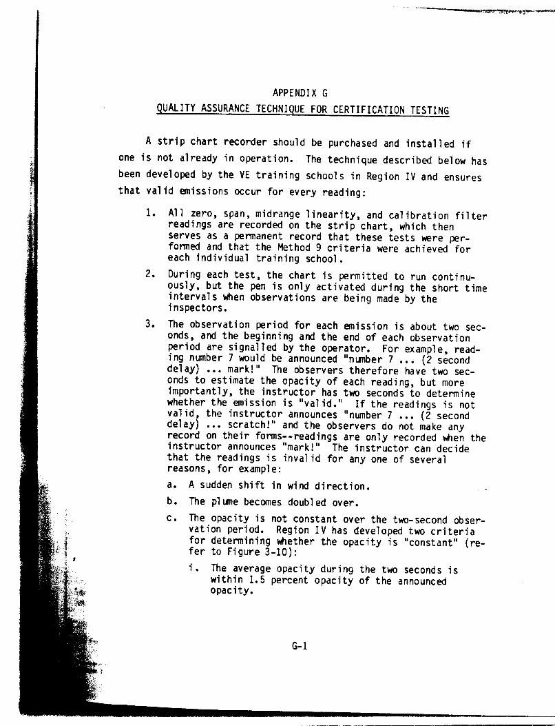
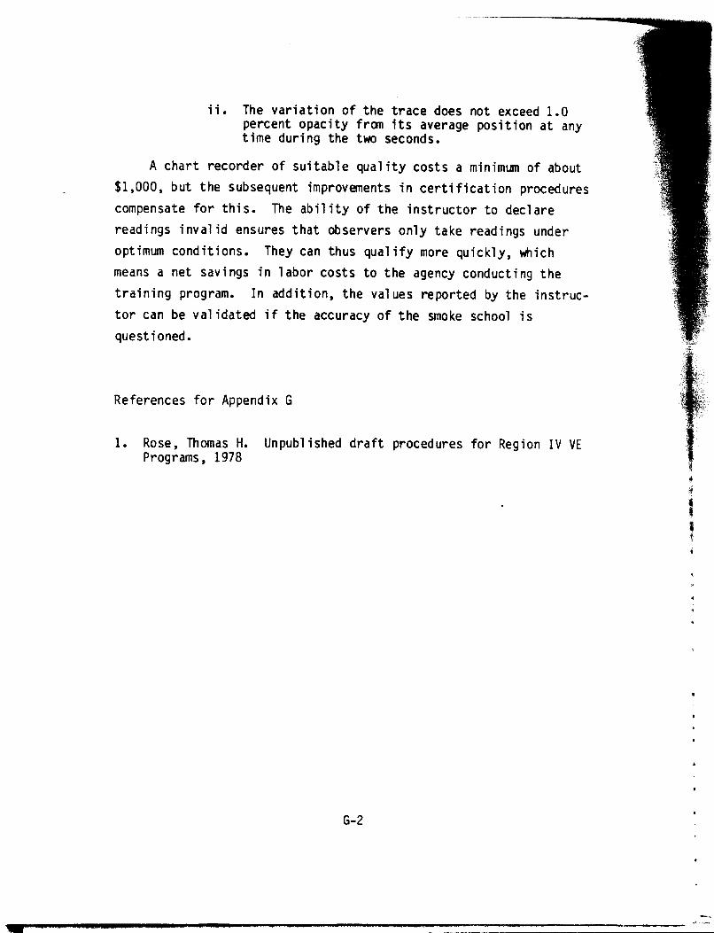
APPENDIX G. QUALITY ASSURANCE TECHNIQUE FOR CERTIFICATION TESTING . . . . . . . . . . . . . . . . . . . . . . . . . G-l
iii
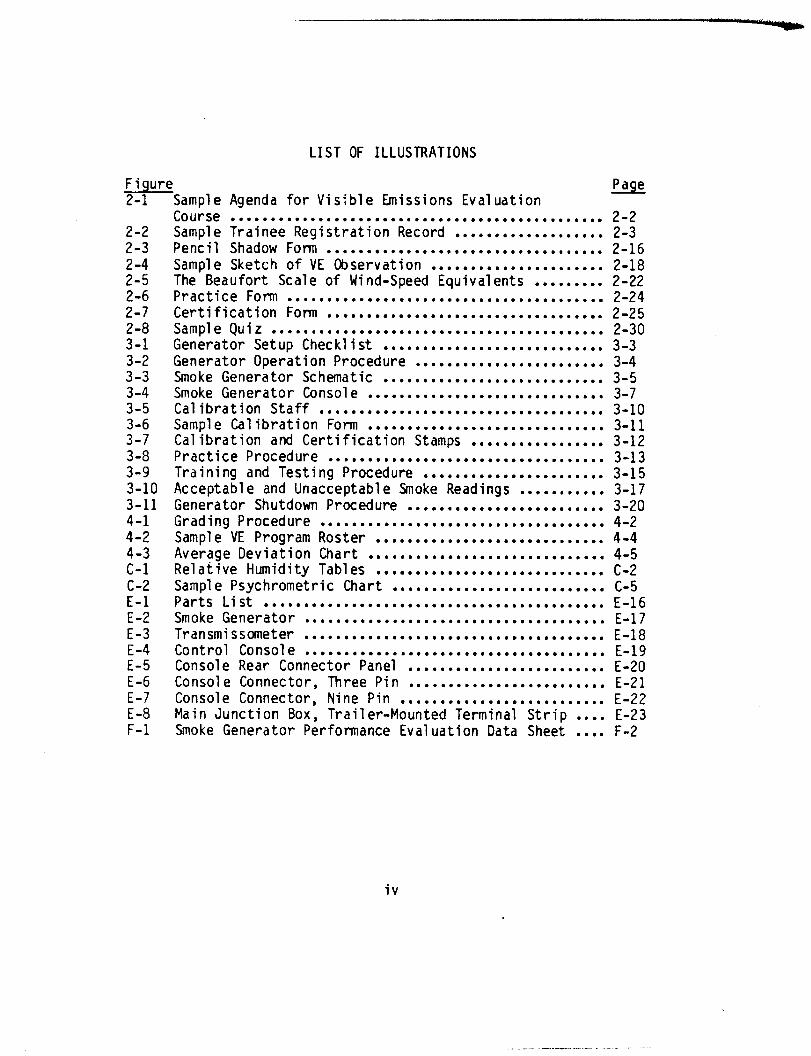
LIST OF ILLUSTRATIONS
EF Sample Agenda for Visible Emissions Evaluation Page
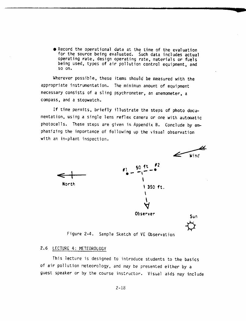
2-2 2-3
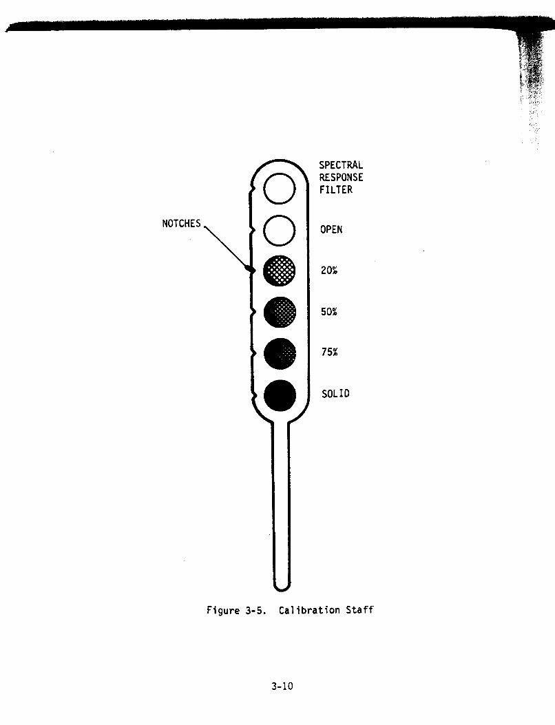
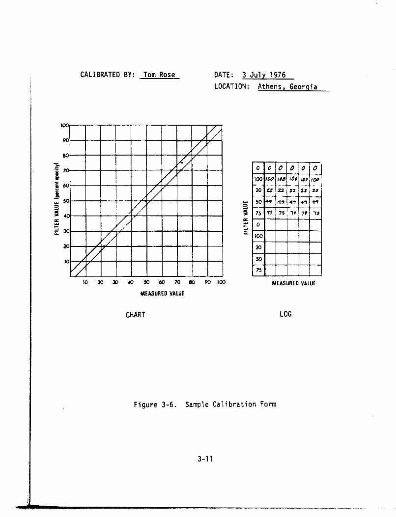
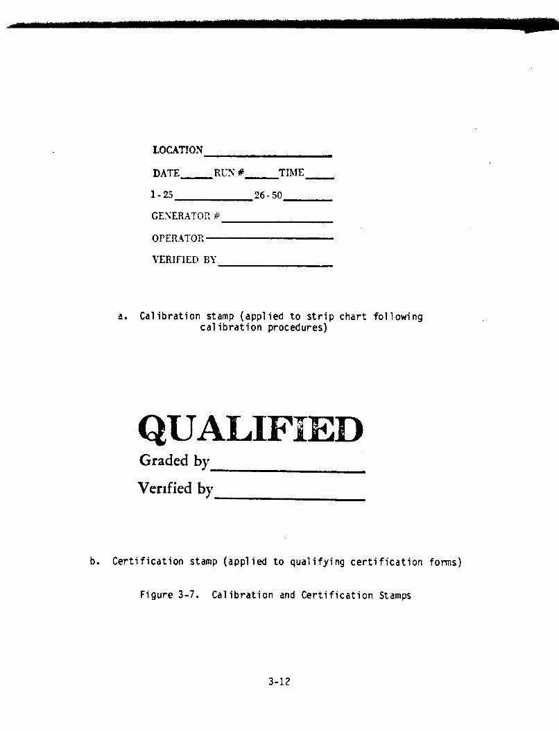
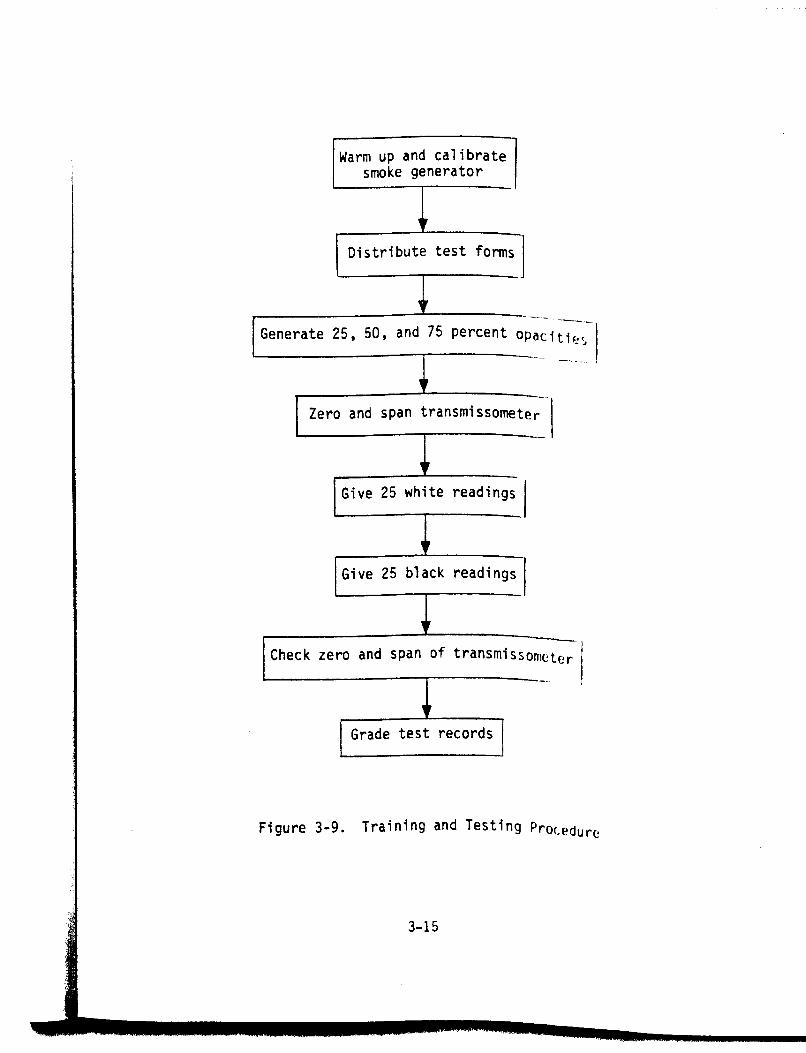
22:; 2-6 2-7 2-8 3-l 3-2 3-3 3-4 3-5 3-6 3-7
33:; 3-10 3-11 4-l 4-2
2:: c-2 E-l E-2 E-3
;:; E-6 E-7 E-8 F-l
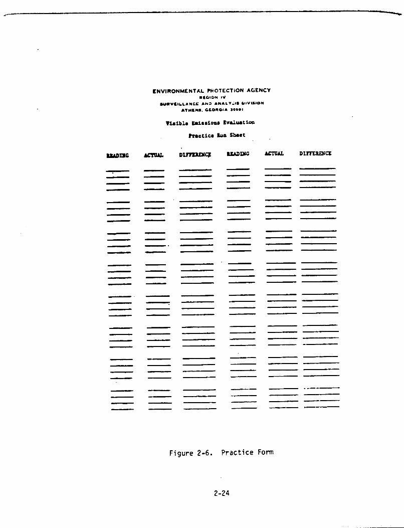
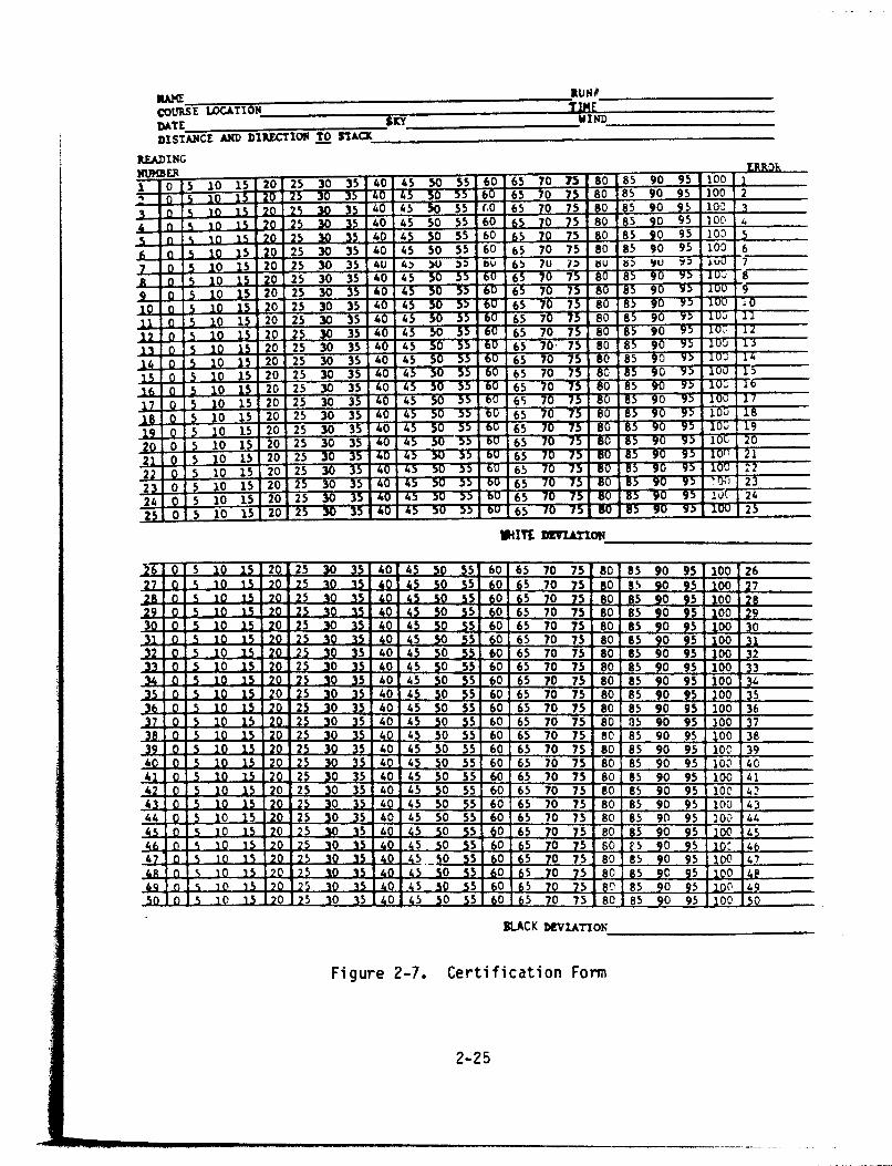
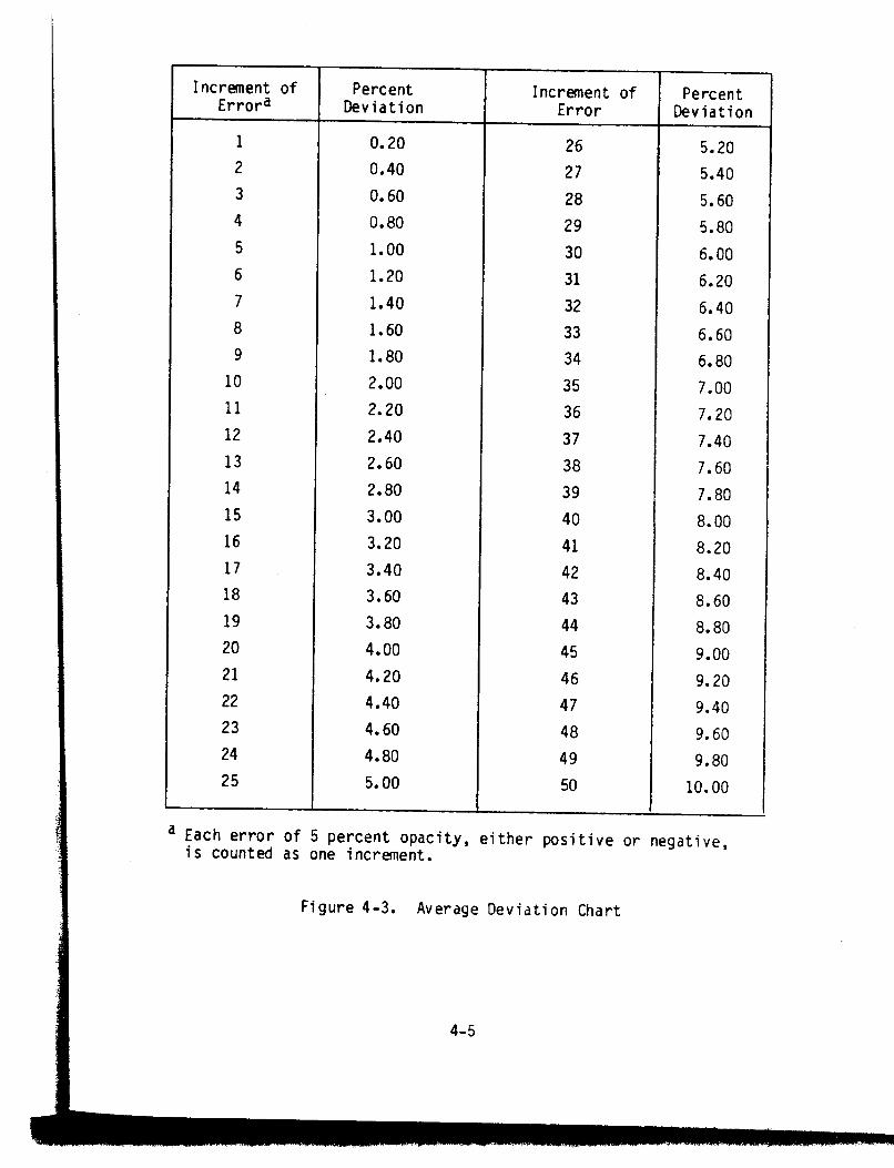
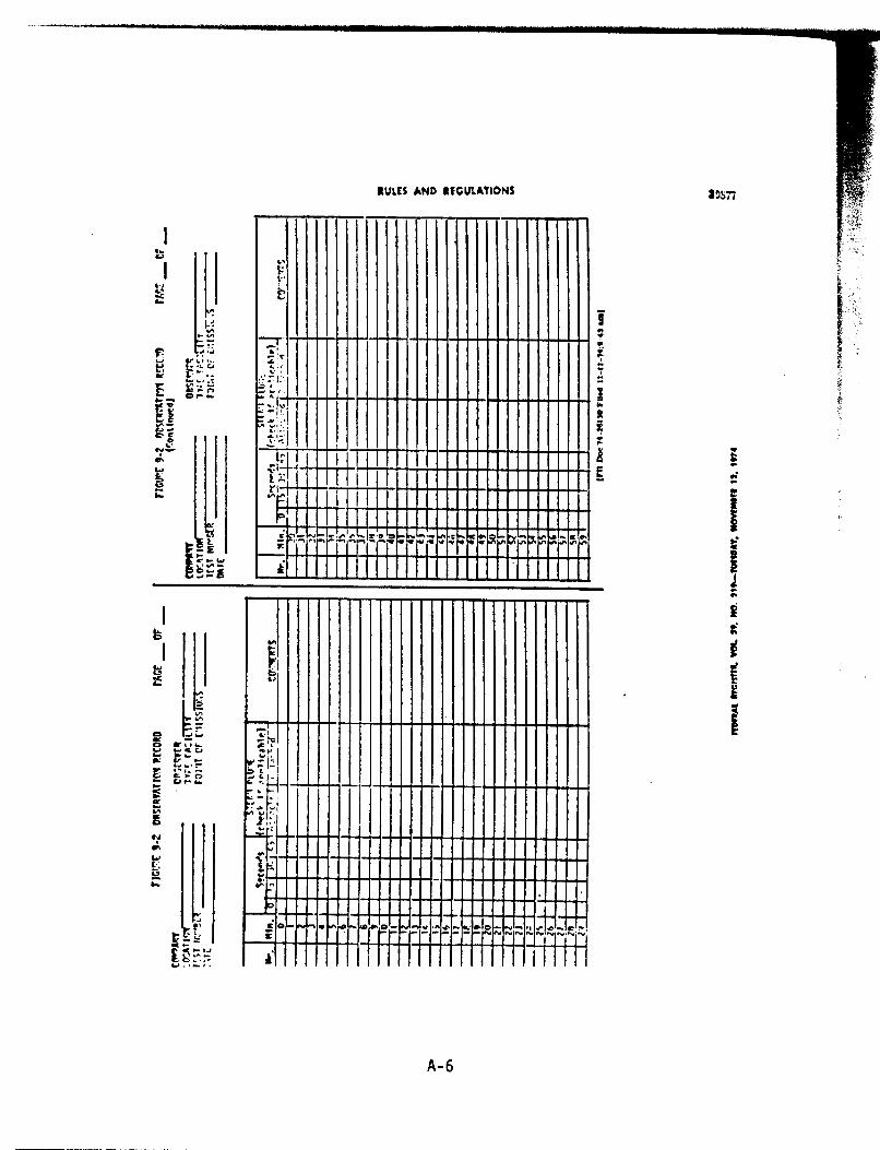
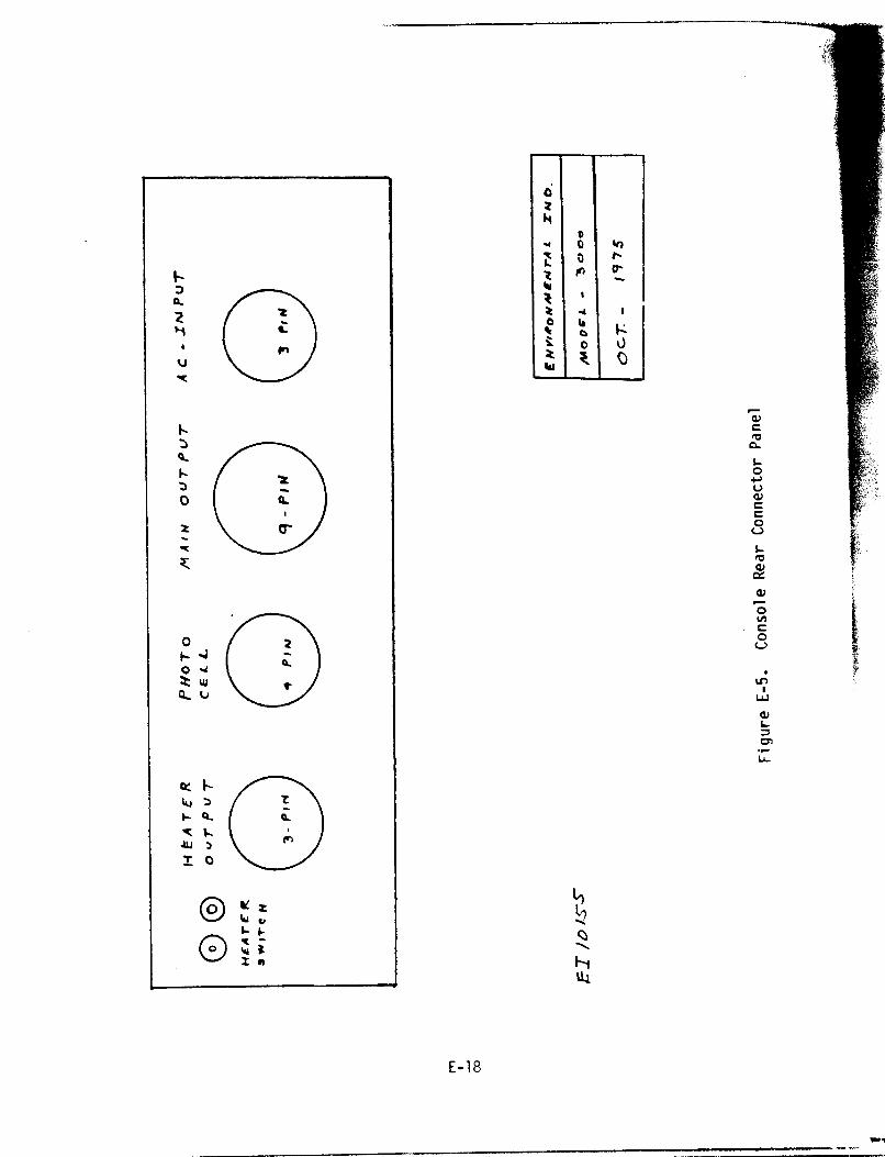
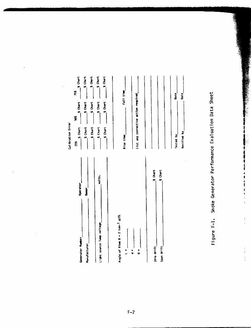
Course ............................................... Sample Trainee Registration Record ................... 22:: Pencil Shadow Form ................................... 2-16 Sample Sketch of VE Observation ...................... 2-18 The Beaufort Scale of Wind-Speed Equivalents ......... 2-22 Practice Form ........................................ 2-24 Certification Form ................................... 2-25 Sample Quiz .......................................... 2-30 Generator Setup Checklist ............................ Generator Operation Procedure ........................ 33:: Smoke Generator Schematic ............................ 3-5 Smoke Generator Console .............................. 3-7 Calibration Staff .................................... 3-10 Sample Calibration Form .............................. 3-11 Calibration and Certification Stamps ................. 3-12 Practice Procedure ................................... 3-13 Training and Testing Procedure ....................... 3-15 Acceptable and Unacceptable Smoke Readings ........... 3-17 Generator Shutdown Procedure ......................... 3-20 Grading Procedure .................................... Sample VE Program Roster ............................. 44:; Average Deviation Chart .............................. 4-5 Relative Humidity Tables ............................. c-2 Sample Psychrometric Chart ........................... c-5 Parts List ........................................... E-16 Smoke Generator ...................................... E-17 Transmissometer ...................................... E-18 Control Console ...................................... E-19 Console Rear Connector Panel ......................... E-20 Console Connector, Three Pin ......................... E-21 Console Connector, Nine Pin .......................... E-22 Main Junction Box, Trailer-Mounted Terminal Strip .... E-23 Smoke Generator Performance Evaluation Data Sheet .... F-2
iv

1.0 INTRODUCTION
This manual was prepared for use by the instructors and smoke
generator operators who conduct EPA Region IV visible emissions
(VE) training programs. It describes the specific smoke generators
owned by Region IV, but is otherwise generally applicable to
training programs throughout the nation. The instructor should
always emphasize the meteorological and other parameters pertinent
to the area where candidates will be evaluating smoke.
Section 2.0 is devoted to the lecture phase of the training
program. It outlines the general content of each suggested talk
and includes a sample agenda for the course. Both lectures and
agenda may be modified or expanded depending on the needs of the
class, since the program described in this manual is a minimal one.
The films and slide shows referred to in this section can be ob-
tained through the Air Surveillance Branch of Region IV EPA.
Section 3.0 discusses the procedures involved in conducting
the certification phase of the program. Generator setup, calibra-
tion, shutdown, and maintenance are included, as well as training
and testing procedures.
Section 4.0 deals with certification criteria and confidence
limits. The appendices include a copy of Method 9, "Visual Deter-
mination of the Opacity of Emissions from Stationary Sources,' and
further details on smoke generator design, specifications, and
testing.
This manual is not intended to be a comprehensive source of
information presented in visible emissions lectures (student manu-
als and other references fill that need). Rather, it is a general
guideline for instructors, including both an outline of key issues
that should be addressed by the speakers and a step-by-step outline
for smoke generator operators in Region IV.
l-l

2.0 THE LECTURE COURSE
2.1 INTRODUCTION
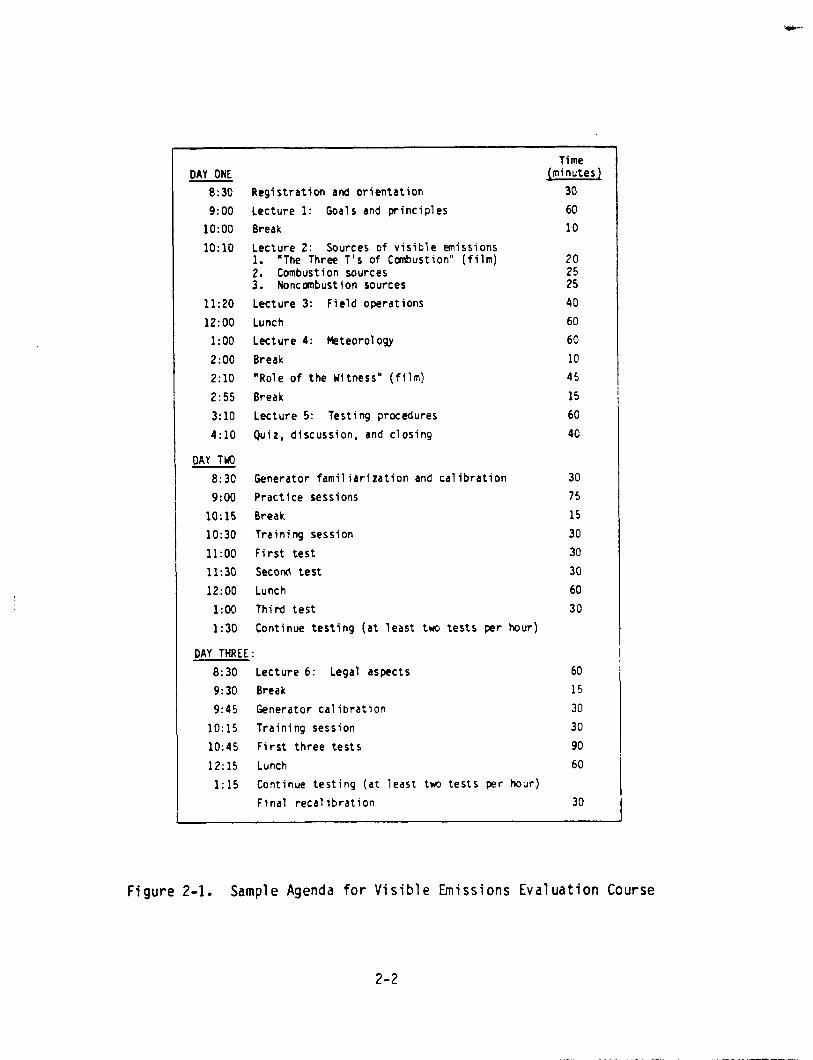
Figure 2-l gives a suggested timetable for the three-day visi-
ble emissions evaluation course. Time allotments and order of pre-
sentation may be modified to accommodate guest speakers, but the
amount of material to be covered requires that a relatively strict
schedule be maintained. Less than three days does not provide suf-
ficient time for both a complete lecture course and the minimum 10
test runs to which students are entitled when attempting to qualify
as VE evaluators.
The purposes of the lecture course are:
l To provide a working knowledge of the principles behind the method of evaluating emissions by the concept of opacity.
l To familiarize the student with the legal rights and re- straints involved in reading visible emissions and in de- fending his observations in court.
l To prepare the student for the certification training and test phase of the program.
These goals are accomplished by a series of lectures, films,
and work sessions conducted on the first day of the visible emis-
sions program. A quiz is administered at the end of the first day
to determine the effectiveness of this lecture course.
2.2 REGISTRATION AND ORIENTATION
Registration is usually conducted by the training officer, al-
though the course instructor may perform this task if necessary. A
brief welcoming address should be given, which is usually presented
by a higher level staff member. Registration and orientation,
which consist primarily of introductions, welcome, and completion
of trainee registration forms (Figure Z-2), involve the following
preliminaries:
2-l
DAY ONE Time
(minutes1
30
60
10
8:30 Registration and orientation
9:00 Lecture 1: Goals and principles
lo:oo Break
1O:lO Lecture 2: Sources of visible emissions 1. "The Three T's of Canbustion" (film) 2. Combustion sources 3. Noncombustion sources
11:20 Lecture 3: Field operations
12:OO Lunch
1:00 Lecture 4: Meteorology
2:00 Break
2:lO "Role of the Witness" (film)
2:55 Break
3:lO Lecture 5: Testing procedures
4:lO Quiz, discussion, and closing
DAY ThQ
B:30 Generator familiarization and calibration
9:oo Practice sessions
lo:15 Break
10:30 Training session
ll:oo First test
11:30 Second test
12:OO' Lunch
l:oo Third test
1:30 Continue testing (at least two tests per hour)
DAY THREE:
8:30 Lecture 6: Legal aspects
9:30 Break
9:45 Generator calibration
10:15 Training session
10:45 First three tests
12:15 Lunch
I:15 Continue testing (at least tm) tests per hour)
Final recalibration
20
::
40
60
60
10
45
15
60
40
30
75
15
30
30
30
60
30
60
15
30
30
90
60
30
Figure 2-1. Sample Agenda for Visible Emissions Evaluation Course
2-2
_ ____._-___ ._-._ - . ._ - - . . . - _ - - - I . I T ” , . - - -

TRAINEE REGISTRATION RECORD - Technical Course
IA51 NAME (4-W
MI.,M~MiS~,
Fositicn Title
Cfvil Service or PHS Ccnntssloned Grade
FIRST NAME W-W
local Residence During Course
EMPLOYER
Address
EDUCATION (Check highest degree obtafncd) (u)
Rachel or CL
Halter 01
Lbctor 0,
Yam of Co1 lcge Tralnlng (Check comet box) Cw)
mfizF@%q
r I !“oFESS10~NA: OR 3CCUPATiONAL CODE W-J*) II 04 Health fducatar OR Sani tartan I
FOR MODERATOR’S USE OS&
01 Admfnl%trrtar OS Indmtrtal Hygfentst 03 Statlsttclarl Cow-w st>rtlng date --- (0.W-l
02 Chemist 06 Hcteorolog~st 15 Technictan a- (I-90)
03 fngineer 07 Physical Scicntfst IX Other Sft Rfvfalt SlOr K-1 COL’F NIJM¶F~
INlllAlCW U.S. CITIZEN 0,)
-fS El, NO [7,
YEARS OF PROFESSIONAL EXPERIENCE <W
pLqyGzq~O,I
EMPLOYER CATEGORY (For U.S. and Foreign lrclnees) Cal-40
;OVERNMENT
FEDW.L (HATIONAL)
EPA (U.S. only)
Oept. of Oefensc
Other Federal
STATE
LOCAL
CL 0.1 q O¶ cl 04 cl 01
UWVERSITY
faculty
Student
IROUSTRY
CONSULTAUT
OTHER
q ” q Jor 0 0:: Cl b
Figure 2-2. Sample Trainee Registration Record

1.
2.
3.
4.
5.
6.
7.
8.
9.
10.
11.
Introduce yourself and welcome the class to the facility and to the course.
State the purpose for and method of conducting the train- ing course in evaluation of visible emissions.
a. The purpose is to train the student so that he or she can qualify as a certified visible emissions evalua- tor, i.e., can determine the opacities of both gray- black and nonblack plumes within 7.5 percent of the correct reading on the average, with no reading incor- rect by more than 15 percent.
b. Half the time is devoted to lectures and half the time to training and test runs using a smoke generator.
i. Lectures include instruction on the sources of visible plumes, the effects of weather on these plumes, the legal basis for visible emissions regu- lations, and certification and field procedures.
ii. Training includes instruction in correctly identi- fying plume opacities, training runs, and actual test runs to establish or re-establish certification.
Have each student introduce him or herself, giving a short background as to where he is from, with whcm he is affili- ated, and so on.
Hand out registration materials and any other student ma- terials not previously distributed, giving any necessary instructions for filling out registration cards.
Point out the locations of restrooms, explain arrangements for coffee during break periods, and so on.
Check that all students have adequate transportation for the remainder of the session.
Suggest convenient restaurants or cafeterias for lunch and mention local spots of interest and scenic attractions in the area.
Give the names and affiliations of any guest speakers tie will be contributing to the course.
Collect the completed registration forms.
If time permits and such a show is available, present a "sound-slide" introduction to the facility.
Have a secretary prepare a class roster to hand out to the students at the end of the first day.
2-4

2.3 LECTURE 1: GOALS AND PRINCIPLES
The purpose of this lecture is to introduce the student to the
history, principles, and practice of conducting visible emissions
evaluations. Visual aids include a 2 x 2 slide projector, screen,
and Visible Emissions Slide Show No. 1.
Begin by re-emphasizing the purpose of conducting the course,
expanding upon and clarifying the introductory remarks made during
orientation. Explain that certification is necessary to assure
accurate VE evaluations, and that it will be discussed in more
detail later in the day (refer to Sections 2.3.3 and 2.8). Then
start the slide talk, covering each of the following points.
2.3.1 HISTORY OF THE METHOD
The official standard for visible emissions evaluation proce-
dures is the current Method 9, "Visual Determination of the Opacity
of Emissions from Stationary Sources," published in the Federal
Register, Volune 39, No. 219, on November 12, 1974 (refer to Ap-
pendix A). All students should have a copy of this document for
study during the training course and for reference during future
field operations.
Explain that Method 9 is the standard method used and approved
by the U.S. Environmental Protection Agency to test for visible
emissions (slide No. 1). It is just as valid as stack testing
methods: in fact, its accuracy is much higher.
The entire visible emissions evaluation system is loosely
based on the principles devised by Maximillian Ringelmann around
the turn of the century in an attempt to measure air polluting
waste from coal-fired boilers (slide No. 2).
The Ringelmann Chart, a method by which the densities of
columns of smoke rising fran stacks may be compared, was one of the
first tools used to measure emissions to the atmosphere (slide No.

3). The chart consists of a scheme by which graduated shades of
gray that vary by five equal steps between white and black can be
accurately reproduced by means of a rectangular grid of black lines
of definite width and spacing on a white background.
In the 1950's, the term “equivalent opacity" was introduced
and the principle of visible emissions evaluation was extended to
other colors of smoke. The modern term is simply "opacity," which
is defined as the obscuring powr of the plume.
The Federal government has discontinued the use of Ringelmann
numbers in Method 9 procedures and in Federal New Source Perform-
ance Standards (NSPS), basing the determination of the optical den-
sity of visible emissions fran stationary sources solely on opacity
(refer to Section 2.3.2). Some state regulations have not made
this change, however, and so continue to operate under a dual sys-
tem in which the Ringelmann Chart is used in the evaluation of
black and gray emissions and equivalent opacity is used for all
other visible emissions.
Certified evaluators must be familiar with both systems of
measurement, but all smoke readings conducted by EPA personnel in
Region IV must be in percent opacity only.
Students should be told that the Ringelmann Chart is actually
unnecessary and that the training they are receiving will enable
them to evaluate the opacity of smoke plumes without such artifi-
cial aids.
2.3.2 OPACITY
The concept of "equivalent opacity" made possible the applica-
tion of the Ringelmann principle to white and other nonblack colors
of smoke. One of the first applications of this concept was in the
1945 air pollution control ordinances of the County of Los Angeles,
which specified that nonblack plumes be judged by the amount of
light that they obscure. The 1947 California Health and Safety
2-6

Code was subsequently amended to limit visible emissions for a giv-
en period of time not only to Ringelmann No. 2 shade of gray, but
also to any opacity that obscures an observer's view to a degree
equal to or greater than Ringelmann No. 2.
Opacity simply means the degree to which an image or back-
ground viewed through the plume is obscured. A good working defin-
ition of opacity is "the obscuring power of the plume expressed in
percent." (Thus reference to an opacity as "equivalent" to a given
Ringelmann number is no longer required or desirable.)
2.3.3 CERTIFICATION
The concept of opacity and the training through which evalua-
tors learn to apply it are presented in a series of smoke schools
that are held all over the country (slide No.4).
Qualifying trainees are certified for 6 months following the
date they successfully complete the lecture and test portions of
the visible emissions evaluation course. Recertification may be
obtained without repeating all of the classroom part of the course
(refer to Section 2.10).
To become certified, observers must read 25 white and 25 black
smoke plunes of varying opacities with a deviation of not more than
7.5 percent for each set of 25 readings and without erring by more
than 15 percent opacity on any single reading. Testing procedures
are explained in detail in Sections 2.8 and 3.6.
The standard of accuracy that students must demonstrate to
become certified is necessary to assure the quality of visible
emissions observations. Only currently certified evaluators can
perform field operations (Section 2.5) and act as expert witnesses
in court (Section 2.10).
2-7
_. -.__ -_- _..- - --
2.3.4 SMOKE GENERATORS
In order to train personnel to evaluate visible emissions, a
smoke generator that produces both black and white smoke and an
instrument that measures the transmission of light through this
smoke are necessary.
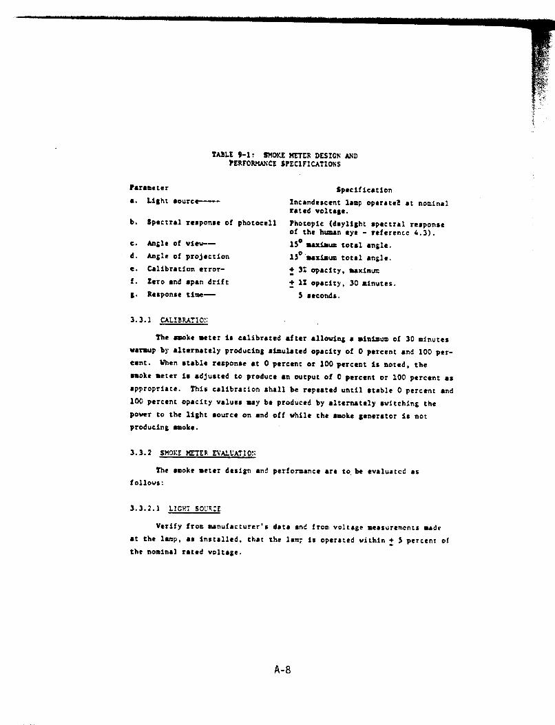
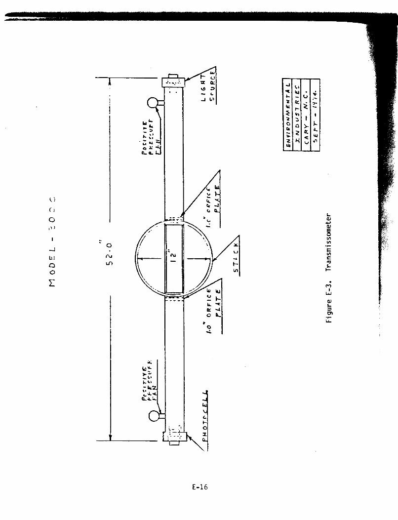
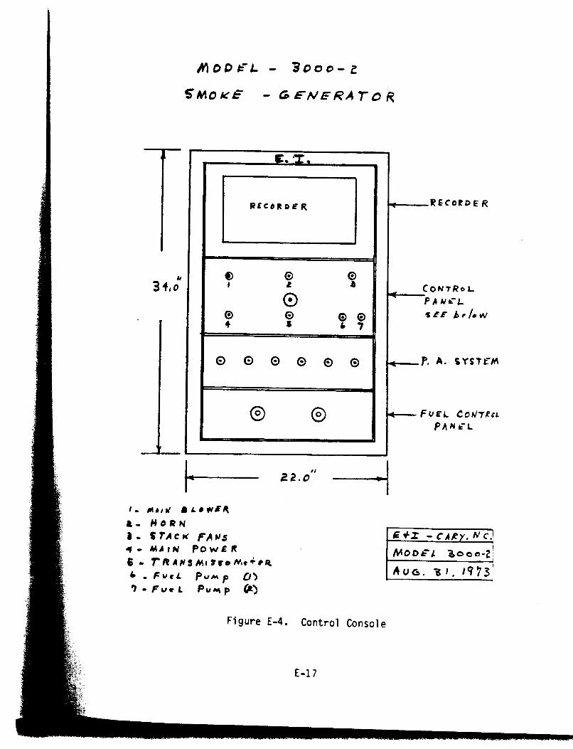
The instrument that measures light passing through the plume
is a transmissometer, which consists of a light source and photo-
cell combination; the percent transmission is indicated by a strip
chart recorder calibrated from 0 to 100 percent opacity. Calibra-
tion is accomplished by means of neutral-density filters. Further
details on the design, calibration, and operation of the smoke gen-
erator are included in the field portion of the course (refer to
Section 3.0).
Black smoke is generated by the incomplete combustion of tolu-
ene or other organic hydrocarbons in a specially designed, insul-
ated combustion chamber (slide No. 5). Smoke density is varied by
adjusting the fuel injection rate. The smoke is pumped through a
fan and up the stack past the transmissometer, which reads the opa-
city of the smoke.
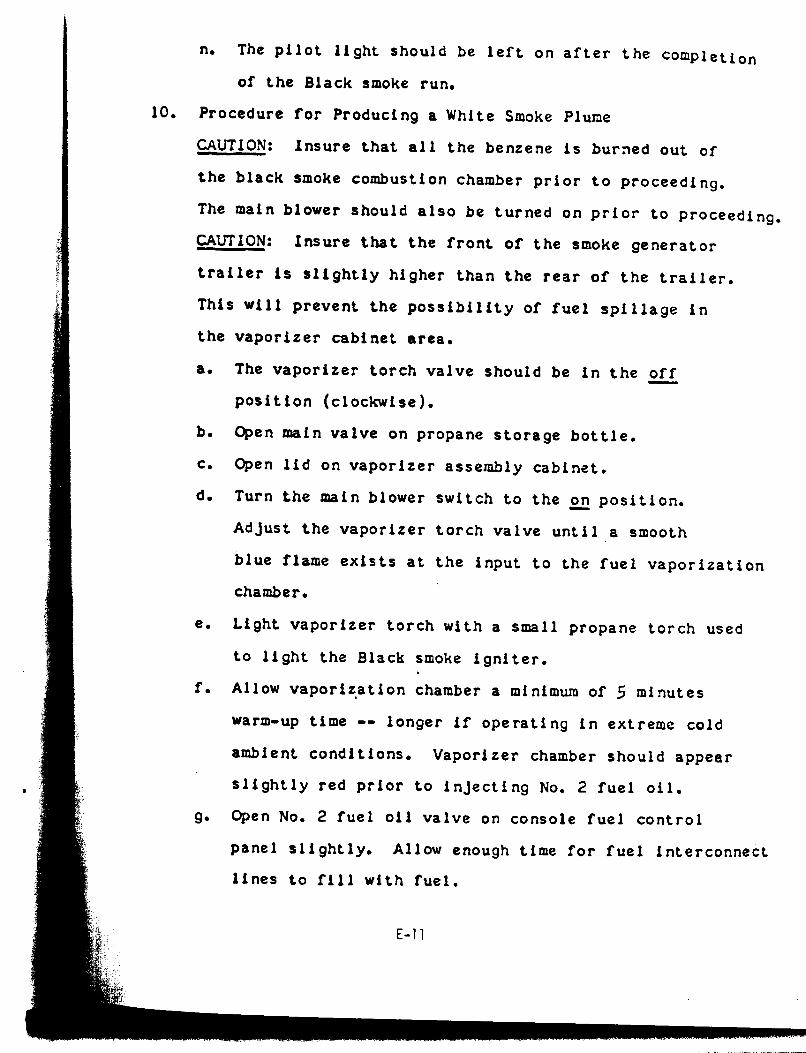
White smoke is generated by vaporizing kerosene or No. 2 fuel
oil on a heated plate or in a hot box (slide No. 6). Smoke density
is controlled by adjusting the fuel flow rate. The white smoke is
also pumped through a fan and past the transmissometer.
The opacity of the smoke depends upon several mechanisms
(slide No. 7):
l Reflection: the return of a ray of light after striking the surface of the smoke particles.
l Refraction: the change of direction of a ray of light in in passing from one medium (air) into another (smoke parti- cles) in which its speed is different. This is similar to a lens or prism effect.
2-8

._..-., L, l.,_-*.UI.l Y---.-.r--IC~-Y_LI le....- . - * -rr.-r.2r.nr--llru.-u-ru^ru-~-.rr--*--IrlU--- -.i.er a*._. . . . - .
l Absorption: the reduction in energy in the form of electro- magnetic radiation by a mediun or by a reflecting surface. Dark-colored smoke particles absorb the energy of the light, thus preventing it fran getting to the detector. (The detector in this case is a phototopic photocell much like that in a camera.)
2.3.5 ADVANTAGES AND DISADVANTAGES OF OBSERVER EVALUATION OF VISIBLE EMISSIONS
Observer evaluation of visible emissions has numerous advan-
tages over stack testing. These include:
l Short training time (24 to 32 hours)
l No extensive technical background needed
l No expensive equipment required
l Many readings per observer per day
l Source testing not necessary in order to cite violators
l Questionable emissions easily located
l Cannot practically test many sources by any other method
One of the main reasons for using the visible emissions method
is its low cost (slide No. 8). Comparison of the cost of the mini-
mum equipment needed for the VE inspector versus that of a conven-
tional stack testing system reveals the truth of this statement: a
sun visor and a compass add up to around $8.35, whereas the samp-
ling procedures, tests, scaffolding, and so on required for Method
5 stack testing can very easily cost about $17,000. The amount of
time for the VE inspection is approximately 1 hour; the time for a
stack test is about 9 man-days.
Moreover, there are numerous facilities that cannot be prac-
tically tested by any method other than smoke reading. A battery
of coke ovens is one such source: a VE inspection would take about
2 days, but stack testing would require all year (slide No. 9).
There are, however, several criticisms of visible emissions
control regulations and the ability of evaluators to enforce them
2-9

objectively. In addition to the variables mentioned in rela-
tion to viewer position (refer to Section 2.3.6), these criticisms
concern the difficulties of accurately evaluating smoke under the I
following conditions:
l When the emissions are gaseous at stack temperature but condense after plume expansion
l At night
a When condensed water vapor is present in the plume
l From within the building housing a point source
l When polluters circumvent regulations by adding more air to the effluent or by building a new stack of smaller diameter for emitting the same quantity of effluent
l When opacity is not well correlated with the amount of material emitted
l In the presence of weather constraints such as raindrops, inclement weather, and high winds that shear the plume
While these objections have a certain degree of validity,
they are mitigated by the following points:
l Opacity is not influenced by night time per se. The light source should be behind the plume when making VE observa- tions during hours of darkness. The light source can be the moon, a star, a street light, or city lights. The densest part of the plume should be between the observer and the lighted object.
I) Visible emissions evaluation programs teach inspectors how to identify the presence of water vapor in plumes and how to read such plumes so as to avoid looking through the "steam" or condensed water vapor.
l Other methods of measuring emissions may be preferable with- in the building housing a point source, but this does not invalidate the method of observer evaluation.
l Circumvention can be detected by comparing current readings with past VE records, which include the location and stack diameter of all observed emission points.
l Opacity limits are enforceable independent of mass emission limits and other standards. Studies such as those by Ensor and Pilat have attempted to calculate smoke plume opacity from particulate air pollutant properties (Reference l), but
Z-10
. . . .
issue. Refer also Cement Association
this remains a complex and controversial to the EPA Response to Remand in Portland v. Ruckelshaus (Reference 2).
l Certified inspectors are aware of the inf luences of weather constraints and do not attempt to make VE observations under inappropriate conditions.
The validity of observer evaluation of visible emissions is
also attested to by the ability of students to learn to read smoke
(slide No. 10). Judging opacity is no different than judging
shades of color. The human eye is capable of selecting a very nar-
row range of the electromagnetic spectrum and identifying its fre-
quency of light. The VE training program consists of calibrating
this type of ability to a scale that distinguishes opacity in in-
crements of 5 percent. This is done by first teaching the student
to recognize 25, 50, and 75 percent opacity, and then giving read-
ings in between these standards.
2.3.6 OBSERVER POSITION
Opacity or smoke density observations may vary according to
the position of the sun, atmospheric lighting, background of the
plune, and size of particles in the plume (slide No. 11). This
variability can be minimized by reading plumes under the following
conditions:
l With the sun in the 140 degree sector to the observer's back, and preferably in a 90 degree sector
l With the wind blowing at approximately right angles to the observer's line of sight and fran a point not less than two stack heights and not more than 0.25 miles from the source
a Against a background that contrasts with the color of the plune
0 With the longer axis of rectangular outlets at approximately right angles to the observer's line of sight
l Through the densest part of the plume and tiere the plume is approximately the diameter of the stack
l With summertime readings avoiding the hours between 10:00 a.m. and 1:30 p.m. (when the sun is high in the sky)
2-11
The major rule is to keep the sun directly over the observer's
back. This and the other guidelines are illustrated by the follow-
ing scenario:
l The deputy comes out to read smoke in the morning and what does he see (slide No. 12)? Can he read smoke? Why not? *
l He comes back after about 4 hours and the sun has moved across the sky (slide No. 13). Now, should he look through line A or line B? Obviously, he should look through line B.
l In fact, the only thing that would make it easier for the deputy to read smoke would be to get a good background (slide No. 14).
Emphasize once again that the correct line of vision is per-
pendicular to the long axis of the plume (slide no. 15). The best
viewing spot is one stack diameter above the stack exit, where the
plume is densest.
Encourage students to observe plumes using different back-
grounds and with the sun located at different angles in order to
demonstrate the effects that these parameters have on observed
opacity (slides No. 16 - 19).
Illustrate what happens to a smoke plume when the wind is
blowing (slide No. 20). Also show how the plume can look very
thick if it is observed along the long axis instead of through it,
and discuss the effects of background (slides No. 21 - 23).
The smoke reading situation is somewhat akin to that of David
and Goliath (slide No. 24), in that the lowly smoke reader, equip-
ped only with his eyes and clipboard, must face the mighty giant of
industry. However, it is not so much the tool you use (slide No.
25), as how well you use it! The importance of correct observer
position cannot be overemphasized. Refer to Section 2.5, Figures
2-3 and 2-4.
2-12
-_‘., _ ,_._, .*,, ~~,,*CN,,,V~‘r’YC*~~~,“,.“‘Y.ZL -..w-llr.u. . ---.-.---..... -------.-v-. - - ------__----------.-- -_ .-, .._ _ .* . ...”
2.3.7 CONDENSED WATER VAPOR PLUMES
Condensed water vapor or "steam" plLlmes are a potential prob-
lem due to aesthetic considerations, visibility reduction, and the
possibility of their masking atmospheric contaminants. Condensed
water vapor is not a pollutant, however, so opacity observations
must be made either beyond or prior to the point where it is visi-
ble in the plune (refer to Appendix A, Sections 2.3.1 and 2.3.2).
The lecture on meteorology (refer to Section 2.6) gives details on
how steam plumes are formed, how to identify and evaluate them, and
how to predict their occurrence through use of a psychrometric
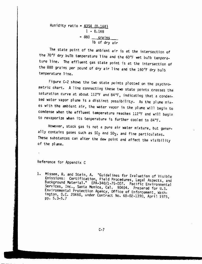
chart (refer also to Appendix C, Figure C-2).
The importance of correctly identifying condensed water vapor
plLanes is illustrated by the following example (slide No. 26). Say
you have two plumes, plume No. 1 and plume No. 2. Which one is
dirtier? Without knowledge of what is contributing to those
plunes, it is impossible to make a judgment. Based on sheer opa-
city, plune No. 2 may appear dirtier. However, its white material
could be-and probably is-condensed water vapor, in which case it
is not pollution. Thus plume No. 1 appears to be much cleaner, but
it is in fact all particulate and is probably the dirtier of the
two.
Condensed water vapor plumes can either be attached to or
detached from the stack exit (slide No. 27). Detached plumes occur
when the entrained water vapor is at too high a temperature and
condenses above the plume, or when sulfuric acid forms above the
plune. This is particularly prevalent where vanadium-containing
fuel oils, such as come from South America, are used in oil-fired
boilers.
2.4 LECTURE 2: SOURCES OF VISIBLE EMISSIONS
This lecture may be given either by an enforcement branch
staff member or by the training course instructor. Visual aids
2-13