vista - vehicle for interplanetary space transport application
DESCRIPTION
UCRL-TR-110500 C. D. Orth LAWRENCE LIVERMORE NATIONAL LABORATORY 0 Disclaimer CONFINE ME N T Charles D. Orth, PhD Systems Analysis Final Report May 16, 2003 I NER T I A L UCRL-LR-110500 S UF N O I Request for copies from LLNL may use either number. NOTE: UCRL-LR-110500 - ii -TRANSCRIPT
0
VISTA – A Vehicle for InterplanetarySpace Transport Application Powered by
Inertial Confinement Fusion
C. D. Orth
May 16, 2003
UCRL-TR-110500
LAWRENCELIVERMORENATIONAL
LABORATORY
Disclaimer
This document was prepared as an account of work sponsored by an agency of the United States Government. Neither the United States Government nor the University of California nor any of their employees, makes any warranty, express or implied, or assumes any legal liability or responsibility for the accuracy, completeness, or usefulness of any information, apparatus, product, or process disclosed, or represents that its use would not infringe privately owned rights. Reference herein to any specific commercial product, process, or service by trade name, trademark, manufacturer, or otherwise, does not necessarily constitute or imply its endorsement, recommendation, or favoring by the United States Government or the University of California. The views and opinions of authors expressed herein do not necessarily state or reflect those of the United States Government or the University of California, and shall not be used for advertising or product endorsement purposes.
This work was performed under the auspices of the U.S. Department of Energy by University of California, Lawrence Livermore National Laboratory under Contract W-7405-Eng-48.
UCRL-LR-110500
V I S T AV I S T AA A VV ehicle for ehicle for II nterplanetary nterplanetary SS pace pace TT ransportransport
AA pplication Powered By Inertial Confinement Fusionpplication Powered By Inertial Confinement Fusion
Charles D. Orth, PhD
Systems Analysis Final Report
I NERTIAL
CONFINEMENT
NOI
SUF
May 16, 2003
LAWRENCE LIVERMORE NATIONAL LABORATORY
University of California • Livermore, California • 94551-0808
UCRL-LR-110500
- ii -
NOTE:
Original Manuscript NumberUCRL-LR-110500
LLNL IM System NumberUCRL-TR-110500
Request for copies from LLNLmay use either number.
UCRL-LR-110500
- iii -
TABLE OF CONTENTS
I. INTRODUCTION.......................................................................................................................2I.1 Transport Concepts for Mars Missions....................................................................................2I.2 The Need to Consider Fusion for Space Propulsion................................................................4I.3 The Development of Fusion-Powered Spacecraft Concepts.....................................................5I.4 The VISTA Concept................................................................................................................6I.5 Intent and Overview of This Report........................................................................................9I.6 Comments on the Reality of ICF ...........................................................................................10
II. THE NATURE OF INERTIAL CONFINEMENT FUSION (ICF) ...................................12II.1 What is fusion?.....................................................................................................................12II.2 What is inertial fusion? ........................................................................................................13II.3 The Advantages of ICF........................................................................................................14II.4 Why don’t we have a terrestrial ICF power plant now? .....................................................15II.5 Why Consider Fusion for Space Propulsion Systems?.........................................................16II.6 Advanced ICF target concepts.............................................................................................17
III. TARGET SYSTEMS..............................................................................................................18III.1 Capsule Design ...................................................................................................................18III.2 Expellant.............................................................................................................................19III.3 Target Fabrication and Assembly......................................................................................20III.4 Target Acceleration, Injection, Tracking, and Beam Pointing...........................................20III.5 Target Performance (Gain)...............................................................................................22III.6 Target Emissions.................................................................................................................24III.7 Advanced Fuels..................................................................................................................25
III.7.1 DD Fuel........................................................................................................................... 25III.7.2 D3He Fuel ........................................................................................................................ 28III.7.3 General Comments about Advanced Fuels and Antimatter .......................................................... 28
III.8 Target and Propellant Storage...........................................................................................29III.9 Onboard Production of Tritium .........................................................................................30
IV. DRIVER SYSTEMS...............................................................................................................32IV.1 A Survey of Terrestrial Driver Developments....................................................................32IV.2 What is a Laser?.................................................................................................................34IV.3 Choice of a DPSSL for VISTA’s Driver.............................................................................35IV.4 A Conceptual Driver Alternative.......................................................................................38IV.5 Beam Line Optics and Focusing .........................................................................................40
V. THRUST CHAMBER SYSTEMS ...........................................................................................42V.1 System Configuration and Basic Engine Operation.............................................................43V.2 Superconducting Magnet .....................................................................................................44V.3 Coil Shield............................................................................................................................47
UCRL-LR-110500
- iv -
V.4 X-Ray Ablation Protection for First Wall & Final Mirrors ................................................48V.5 Target Debris Plasma Physics..............................................................................................49V.6 Plume Formation and Plasma Collection Efficiency............................................................51V.7 Jet Efficiency........................................................................................................................51V.8 Inductor EMF Power Conversion Option............................................................................53V.9 Blanket Options....................................................................................................................53V.10 Shock Isolation...................................................................................................................54
VI. POWER SYSTEMS...............................................................................................................55VI.1 Overall Concepts................................................................................................................55VI.2 Overall Power Flow...........................................................................................................57VI.3 Inductor Power System.......................................................................................................58
VI.3.1 Inductor Power Conversion Subsystem.................................................................................. 59VI.3.2 Inductor Power Conditioning Subsystem................................................................................ 59
VI.4 Rankine Power System.......................................................................................................59VI.4.1 Rankine Power Conversion Subsystem.................................................................................. 60VI.4.2 Rankine Power-Conditioning Subsystem ............................................................................... 62
VI.5 Energy Multiplication Factor .............................................................................................63VI.6 Auxiliary Power System.....................................................................................................63VI.7 Engine Startup Power System.............................................................................................64VI.8 Uncertainties in Power Generation and Their Effects.........................................................64
VII. THERMAL CONTROL SYSTEMS .....................................................................................65VII.1 Concepts and Effects of Technology Development.............................................................65VII.2 Radiator Design With Micrometeoroid Shields.................................................................66VII.3 Refrigeration Systems........................................................................................................68VII.4 Thermal Systems for the Magnet Coil Shield.....................................................................68VII.5 Thermal Systems for the Final Laser Mirrors...................................................................68
VIII. CREW SYSTEMS ...............................................................................................................69VIII.1 Types of Crew Systems.....................................................................................................69VIII.2 Crew Safety......................................................................................................................69VIII.3 Crew System Masses ........................................................................................................70
VIII.3.1 Crew Environment........................................................................................................... 70IX. SPACECRAFT DESIGN.......................................................................................................72
IX.1 Design Requirements ..........................................................................................................72IX.2 Configuration Layout.........................................................................................................72IX.3 Final Turning Mirror Structure .........................................................................................74IX.4 Integration of Conical Shell and Radiator Structure..........................................................74IX.5 Assembly in Orbit...............................................................................................................74
X. ENVIRONMENTAL HAZARDS............................................................................................75X.1 Tritium Hazards ..................................................................................................................75
X.1.1 Tritium Hazards for Fuel Transport Up Through the Atmosphere................................................. 75

UCRL-LR-110500
- v -
X.1.2 Tritium Hazards for Onboard Crew Members............................................................................ 79X.2 Neutron Activation of Spacecraft Components....................................................................79X.3 Neutron Hazards to Other Spacecraft .................................................................................80X.4 Exhaust and Particulate Hazards to Other Spacecraft ........................................................80
XI. TRAJECTORY ANALYSIS FOR MARS MISSIONS.........................................................81XI.1 Simple Approximate Analysis............................................................................................81XI.2 Differences From Our Previous Publications .....................................................................85XI.3 Loss in Performance due to Mass Contingencies ................................................................85XI.4 Loss in Performance due to ALL System Uncertainties......................................................87
XII. TRAJECTORY ANALYSIS FOR MISSIONS BEYOND MARS......................................89XII.1 General Results .................................................................................................................89XII.2 Loss in Performance due to ALL System Uncertainties.....................................................89
XIII. MISSIONS BEYOND THE SOLAR SYSTEM.................................................................91XIV. DEVELOPMENT STRATEGY and TECHNOLOGY READINESS ...............................93
XIV.1 Critical Development Issues .............................................................................................93XIV.2 Current Status..................................................................................................................95XIV.3 Realistic Development Schedule and Costs.......................................................................96XIV.4 Recommendation for Studies of Ways to Reduce Tritium Requirements .........................98XIV.5 Preliminary Technology Readiness Assessment...............................................................99XIV.6 A Fast-Track Approach to Fusion Propulsion..............................................................100
XIV.6.1 Synergism Possible From a NASA-DOE Dual Approach.......................................................100XIV.6.2 Differences Between Terrestrial and Space Applications..........................................................101XIV.6.3 Shifting Toward a Fast-Track Approach..............................................................................101XIV.6.4 Fast-Track R&D Roadmap...............................................................................................104XIV.6.5 NASA R&D Funding Profile ...........................................................................................106
XV. ADVANCED-TECHNOLOGY CONSIDERATIONS ......................................................108XV.1 Near-Future Advancements............................................................................................108XV.2 Far-Future Advancements..............................................................................................109
XVI. COMPARISON WITH OTHER TECHNOLOGIES.......................................................111XVI.1 Magnetic Confinement Fusion (MCF)...........................................................................111XVI.2 Nuclear Electric Propulsion (NEP) Concepts................................................................112XVI.3 Antimatter-Initiated Fission/Fusion................................................................................112XVI.4 Orion-Type Pusher-Plate Concepts Using Nuclear Explosions......................................113XVI.5 General Considerations .................................................................................................113
XVII. CONCLUSIONS..............................................................................................................118APPENDIX A: HIGH-PERFORMANCE SPACECRAFT SCALING ..................................119ACKNOWLEDGMENTS...........................................................................................................138REFERENCES...........................................................................................................................138

UCRL-LR-110500
- vi -
LIST OF FIGURES
I-1 The VISTA Spacecraft Configuration . . . . . . . . . . . . . . . . . . . . . . . . . 8
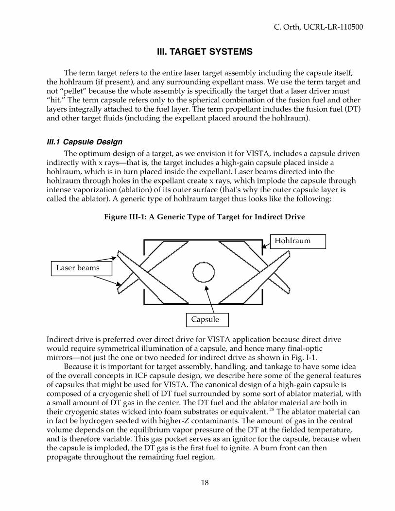
III-1 A Generic Type of Target for Indirect Drive . . . . . . . . . . . . . . . . . . . 18
V-1 Magnetic Thrust Chamber Operation . . . . . . . . . . . . . . . . . . . . . . . . . 42
V-2 Superconducting Magnet/Shield Conceptual Design . . . . . . . . . . . 45
VI-1 Overall Power Flow with Inductor Power System. . . . . . . . . . . . . . 57
VI-2 Overall Power Flow with Ranking Power System. . . . . . . . . . . . . . 58
VI-3 Rankine-Cycle Power Flow Diagram . . . . . . . . . . . . . . . . . . . . . . . . . . 60
XI-1 Comparison of Approximate/Exact Alpha Curves for Mars . . . . . 82
XI-2 Performance Variation with Driver Efficiency, Radiator Tech. . . . 84
XI-3 Performance Variation with Target G, Driver T, Payload M. . . . . . 84
XIV-1 Terrestrial IFE Development Strategy . . . . . . . . . . . . . . . . . . . . . . . . . 97
XIV-2 DPSSL Integrated Research Experiment Configuration . . . . . . . . . . 98
XIV-3 Roadmap for Development of Nuclear Fusion Propulsion . . . . . . 105
XIV-4 Estimated NASA Fast-Track Direct-Cost Funding Profile . . . . . . . . 107
UCRL-LR-110500
- vii -
LIST OF TABLES
I-1 General Assumptions for Project VISTA . . . . . . . . . . . . . . . . . . . . . 6
II-1 Attributes of Various Power Sources . . . . . . . . . . . . . . . . . . . . . . . . . 17
III-1 Target Gains for Different Fuel Masses . . . . . . . . . . . . . . . . . . . . . . . . 24
IV-1 Desired Features of VISTA’s Target Driver. . . . . . . . . . . . . . . . . . . . . 32IV-2 Excimer Laser Processes . . . . . . . . . . . . . . . . . . . . . . . . . . . . . . . . . . . . . 39
V-1 Assumed Magnet Coil Matrix Composition . . . . . . . . . . . . . . . . . . . 46V-2 Magnet Coil Parameters . . . . . . . . . . . . . . . . . . . . . . . . . . . . . . . . . . . . . 46V-3 Magnet and Shield Composition . . . . . . . . . . . . . . . . . . . . . . . . . . . . . 47
XI-1 Parameters Assumed for Advanced-Technology Case . . . . . . . . . . 82XI-2 Distribution of Mass for Advanced Mission to Mars . . . . . . . . . . . . 83XI-3 Effect of mass contingencies on Mars Roundtrip Performance . . . 85XI-4 VISTA Mass Properties Table With Contingencies . . . . . . . . . . . . . 86XI-5 Monte Carlo Variations in Trip Times to Mars . . . . . . . . . . . . . . . . 88
XII-1 Mission Durations to the Planets for Different Target Gains . . . . . 89XII-2 Monte Carlo Variations in Trip Times to Jupiter and Pluto . . . . . 90
XIII-1 DT Missions Beyond Pluto . . . . . . . . . . . . . . . . . . . . . . . . . . . . . . . . . . . 91XIII-2 Time and Kinetic Energy Required to Get to 104 AU. . . . . . . . . . . . . 91
XIV-1 Development Issues for VISTA . . . . . . . . . . . . . . . . . . . . . . . . . . . . . . . 93XIV-2 Technology Readiness Level Estimates . . . . . . . . . . . . . . . . . . . . . . . . 100XIV-3 One Possible DOE Roadmap for IFE . . . . . . . . . . . . . . . . . . . . . . . . . . . 102XIV-4 ICF Fusion-Propulsion Milestones and Key Decision Points . . . . . 103XIV-5 NASA Fast-Track Fusion Propulsion Development Funding . . . . 106
XV-1 Mars Missions With Different Target Fuels . . . . . . . . . . . . . . . . . . . . 108XV-2 Mars Missions With Antimatter Fuel . . . . . . . . . . . . . . . . . . . . . . . . . 109

UCRL-LR-110500
- viii -
PREFACE
This document represents the final report for the original VISTA systems studyconducted in 1986 and 1987 by the following individuals, who formed the systemsanalysis team:
Charles D. OrthLawrence Livermore National Laboratory, Livermore, CA
Gail Klein and Joe SercelJet Propulsion Laboratory, Pasadena, CA
Nathan Hoffman and Kathy Murray(Formerly of) ETEC/Rocketdyne/Rockwell, Canoga Park, CA
Franklin Chang DiazNASA, Astronaut Office, Johnson Space Center, Houston, TX
Many other people in addition to those listed above contributed to this original study,including Bill Hogan and Max Tabak at the Lawrence Livermore National Laboratory(LLNL) and Hoppy Price, Stan Krauthamer, Carl Sauer, Andrey Sergeyevsky, KatieBarhydt, Alok Chatterjee, and Jayant Sharma at the Jet Propulsion Laboratory (JPL).
The original study was conducted to determine whether inertial confinementfusion (ICF) could be adapted for piloted space transport to Mars with a sufficientincrease in speed over conventional rocket technology that the physiologicaldeteriorations from exposures to zero gravity and cosmic rays could be reduced to amanageable level. The study was very successful, and produced the VISTA spacecraftconcept, which is still the leading ICF-powered spacecraft concept in the world.
Since the late 1980’s, the lead author has made extensive additions andimprovements to the original study by (1) making the system mass estimates morerealistic, (2) detailing the design of certain systems such as the superconducting magnetin the magnetic thrust chamber, (3) writing his own simple analytic mission-trajectorycomputer code to do approximate but comprehensive systems analysis combining bothspacecraft system masses and mission trajectories, (4) extending the results todestinations other than Mars, and (5) writing and assembling this report. Theseextensions proved to be very important. For example, the minimum mission durationfor a roundtrip to Mars has increased from 90 days to a more realistic 145 days. Thisdocument therefore includes a description of these enhancements and the extendedmission analyses in addition to the methodology used in the original systems study.

C. Orth, UCRL-LR-110500
1
VISTA--A Vehicle for Interplanetary Space Transport ApplicationPowered by Inertial Confinement Fusion
ABSTRACT
Inertial Confinement Fusion (ICF) is an ideal technology to power self-containedsingle-stage piloted (manned) spacecraft within the solar system because of its inherentlyhigh power/mass ratios and high specific impulses (i.e., high exhaust velocities). Thesetechnological advantages are retained when ICF is utilized with a magnetic thrust chamber,which avoids the plasma thermalization and resultant degradation of specific impulse thatare unavoidable with the use of mechanical thrust chambers. We started with Rod Hyde’s1983 description of an ICF-powered engine concept using a magnetic thrust chamber,1 andconducted a more detailed systems study to develop a viable, realistic, and defensiblespacecraft concept based on ICF technology projected to be available in the first half of the21st century. The results include an entirely new conical spacecraft conceptual designutilizing near-existing radiator technology. We describe the various vehicle systems for thisnew concept, estimate the missions performance capabilities for general missions to theplanets within the solar system, and describe in detail the performance for the baselinemission of a piloted roundtrip to Mars with a 100-ton payload. For this mission, we showthat roundtrips totaling ≥145 days are possible with advanced DT fusion technology and atotal (wet) spacecraft mass of about 6000 metric tons. Such short-duration missions areadvantageous to minimize the known cosmic-radiation hazards to astronauts, and are evenmore important to minimize the physiological deteriorations arising from zero gravity.These ICF-powered missions are considerably faster than those available using chemical ornuclear-electric-propulsion technologies with minimum-mass vehicle configurations. VISTAalso offers onboard artificial gravity and propellant-based shielding from cosmic rays, thusreducing the known hazards and physiological deteriorations to insignificant levels. Weemphasize, however, that the degree to which an ICF-powered vehicle can outperform avehicle using any other realistic technology depends on the degree to which terrestrial-based ICF research can develop the necessary energy gain from ICF targets. Withaggressive progress in such terrestrial research, VISTA will be able to make roundtripmissions to Pluto in ~7 years, and missions to points just beyond the solar system within ahuman lifetime.

C. Orth, UCRL-LR-110500
2
I. INTRODUCTION
Man has always had a fascination for space travel and exploration of the universe.Great progress has already been made in exploring the Earth and the moon with piloted(manned) and unpiloted (unmanned) space missions, and in exploring other nearby bodiesin the solar system using unpiloted probes. The focus for piloted transport in the next fewdecades will undoubtedly be missions to Mars—provided the desire and will to go there cankindle the development of the appropriate technology to get astronauts there and back in asafe manner.
Specifically, in 1990, President Bush approved a National Space Policy Directivereaffirming the commitment of the United States to space exploration, and outlining thesteps to achieve the 1988–1992 Space Exploration Initiative (SEI) that included both pilotedand unpiloted missions to the Moon and to Mars. His desire was to achieve pilotedexploration of Mars by AD 2019. NASA therefore considered strategies for pilotedinterplanetary missions, specifically, a series of roundtrips to the surface of Mars, leading tothe eventual establishment of a permanent Mars base.2 More recently, NASA’s JetPropulsion Laboratory (JPL) sent an orbiter (Mars Global Surveyor) and a lander (MarsPathfinder) to Mars in 1996, and plans to fly two missions to Mars about every 26 monthsthrough 2005 as part of its Mars Exploration Program. Thereafter, the mission emphasis willprobably shift to more distant planets and missions beyond the solar system.
Although much experience will presumably be required during Shuttle, lunar, andSpace-Station missions prior to any piloted mission to another planet, it seems likely that apiloted mission to Mars will be the ultimate focus of the U.S. space program for the early21st century.3 In this report, we focus on such interplanetary transport, and consider apiloted mission to Mars as the most relevant interplanetary mission.
I.1 Transport Concepts for Mars MissionsMost discussions of vehicle concepts for interplanetary transport have assumed the
use of chemical fuels, with some mention of nuclear-fission-powered engines. Such a focusreflects near-term technology, which permits roundtrip missions to Mars with flightdurations of typically one to three years using minimum-mass configurations. Such flightdurations might seem satisfactory, except that the U.S. space flights already completed havedemonstrated that space is a very hazardous radiation environment for such lengthymissions,4 and USSR Souyez flights have demonstrated that man's skeletal physiologysuffers significantly for durations exceeding about 100 days in zero gravity. Longer flightdurations result not only in astronauts being unable to stand up or walk without assistance,but also in a range of associated blood and physiological symptoms.5 In addition, for flightsexceeding roughly one year, the galactic cosmic radiation produces significant physiologicaldeterioration, resulting in predicted leukemias and associated ailments.6 Typically, anygiven human cell will be struck once every three days by a cosmic-ray proton, once amonth by a helium ion, once in 9 years by a heavy ion with charge between 10 (neon) and26 (iron), and 6% of all cells will be hit two or more times by such heavy nuclei in a three-year mission.7 Thus, potential physiological problems are becoming the most pressingconcern of astronauts. Astronauts are therefore emphasizing the need for propulsionsystems that will shorten mission durations.
C. Orth, UCRL-LR-110500
3
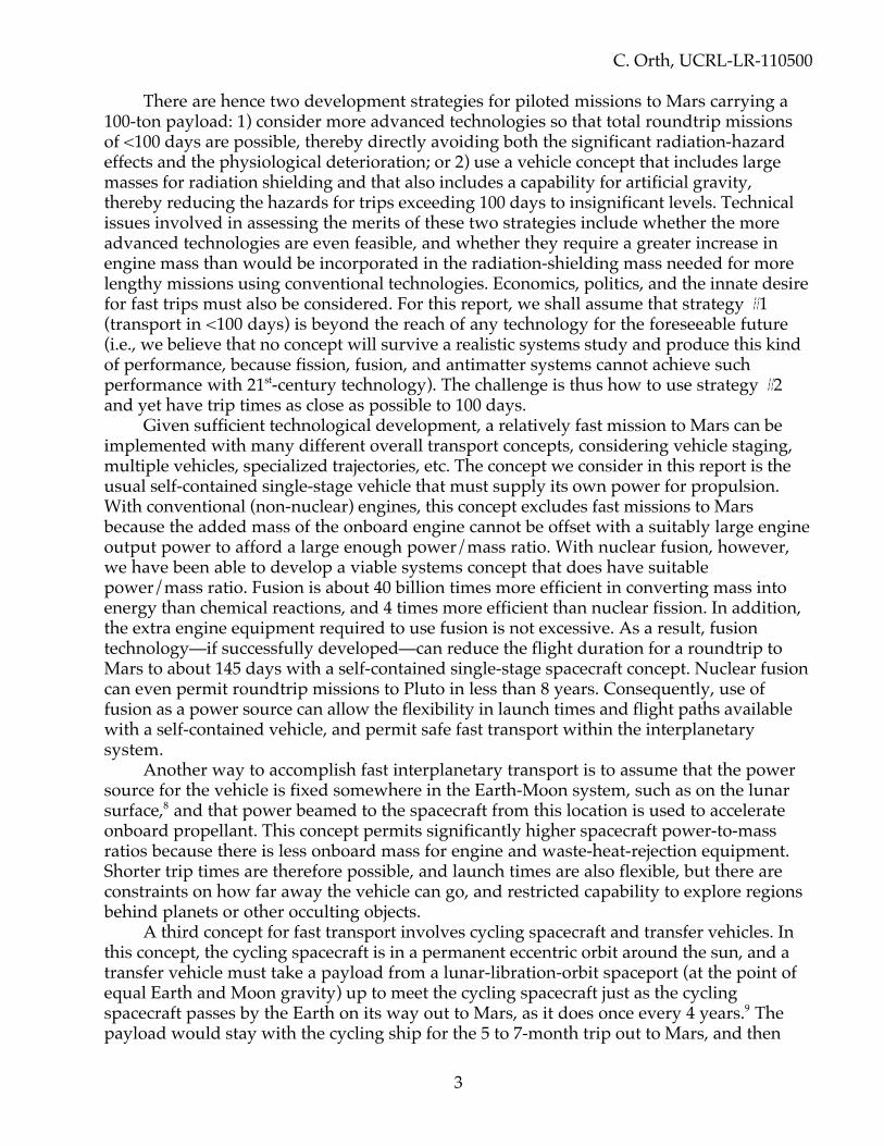
There are hence two development strategies for piloted missions to Mars carrying a100-ton payload: 1) consider more advanced technologies so that total roundtrip missionsof <100 days are possible, thereby directly avoiding both the significant radiation-hazardeffects and the physiological deterioration; or 2) use a vehicle concept that includes largemasses for radiation shielding and that also includes a capability for artificial gravity,thereby reducing the hazards for trips exceeding 100 days to insignificant levels. Technicalissues involved in assessing the merits of these two strategies include whether the moreadvanced technologies are even feasible, and whether they require a greater increase inengine mass than would be incorporated in the radiation-shielding mass needed for morelengthy missions using conventional technologies. Economics, politics, and the innate desirefor fast trips must also be considered. For this report, we shall assume that strategy #1(transport in <100 days) is beyond the reach of any technology for the foreseeable future(i.e., we believe that no concept will survive a realistic systems study and produce this kindof performance, because fission, fusion, and antimatter systems cannot achieve suchperformance with 21st-century technology). The challenge is thus how to use strategy #2and yet have trip times as close as possible to 100 days.
Given sufficient technological development, a relatively fast mission to Mars can beimplemented with many different overall transport concepts, considering vehicle staging,multiple vehicles, specialized trajectories, etc. The concept we consider in this report is theusual self-contained single-stage vehicle that must supply its own power for propulsion.With conventional (non-nuclear) engines, this concept excludes fast missions to Marsbecause the added mass of the onboard engine cannot be offset with a suitably large engineoutput power to afford a large enough power/mass ratio. With nuclear fusion, however,we have been able to develop a viable systems concept that does have suitablepower/mass ratio. Fusion is about 40 billion times more efficient in converting mass intoenergy than chemical reactions, and 4 times more efficient than nuclear fission. In addition,the extra engine equipment required to use fusion is not excessive. As a result, fusiontechnology—if successfully developed—can reduce the flight duration for a roundtrip toMars to about 145 days with a self-contained single-stage spacecraft concept. Nuclear fusioncan even permit roundtrip missions to Pluto in less than 8 years. Consequently, use offusion as a power source can allow the flexibility in launch times and flight paths availablewith a self-contained vehicle, and permit safe fast transport within the interplanetarysystem.
Another way to accomplish fast interplanetary transport is to assume that the powersource for the vehicle is fixed somewhere in the Earth-Moon system, such as on the lunarsurface,8 and that power beamed to the spacecraft from this location is used to accelerateonboard propellant. This concept permits significantly higher spacecraft power-to-massratios because there is less onboard mass for engine and waste-heat-rejection equipment.Shorter trip times are therefore possible, and launch times are also flexible, but there areconstraints on how far away the vehicle can go, and restricted capability to explore regionsbehind planets or other occulting objects.
A third concept for fast transport involves cycling spacecraft and transfer vehicles. Inthis concept, the cycling spacecraft is in a permanent eccentric orbit around the sun, and atransfer vehicle must take a payload from a lunar-libration-orbit spaceport (at the point ofequal Earth and Moon gravity) up to meet the cycling spacecraft just as the cyclingspacecraft passes by the Earth on its way out to Mars, as it does once every 4 years.9 Thepayload would stay with the cycling ship for the 5 to 7-month trip out to Mars, and then

C. Orth, UCRL-LR-110500
4
decouple for a transfer to the appropriate Mars orbit. The return trip to Earth wouldrequire waiting about one year on the planet to catch the cycling spacecraft on its way backtoward the sun. This concept may save resources for many missions, but it restricts launchopportunities and choices for destinations (even with multiple cycling spacecraft), involvesanother crew which must be in space for extended periods, prolongs the stay on Mars, andlimits how fast the trip can be made. A variation of this concept is to use rotating tetheredsystems circling Earth and Mars,10 but such systems assume pickup and dropoff of payloadsat about 2 km/s in eccentric sub-orbital planetary orbits using tethered masses roughly 15times more massive than the payload.
Although these and other concepts permit fast interplanetary transport, we chose toconsider only the first concept, that is, a self-contained single-stage spacecraft. In particular,the objective for the study reported here was to specify a viable vehicle systems concept forpiloted missions within the solar system that would incorporate technology available in thefirst half of the 21st century and enable transport of 100-ton payloads to Mars and back in atime as close as possible to 100 days. We included the 100-day criterion to minimize thephysiological deteriorations to astronauts resulting from zero gravity, as well as theinduced-cancer hazards resulting from in-flight cosmic-radiation exposures, even thoughwe planned to develop a concept that could provide artificial gravity and cosmic-rayshielding for safe missions of longer durations. An additional purpose for including thenear-100-day requirement was to demonstrate the advantages of nuclear fusion, becausesuch fast relatively near-term piloted missions cannot be accomplished using minimum-mass configurations and either chemical or nuclear-fission technologies. As it turned out,our design not only demonstrates the need for the development of fusion propulsion, butalso allows safe transport to any point within the solar system even though the roundtripflight durations exceed the 100-day requirement.
I.2 The Need to Consider Fusion for Space PropulsionWith our current understanding, propulsion systems based on nuclear fusion are
expected to provide the fastest transport to Mars in the 21st century. Systems based onnuclear fission (e.g., nuclear-electric propulsion), although closer to reality than fusionsystems, can only provide roundtrips to Mars of two-thirds of a year or more—certainlynothing close to 145 days. Thus, if man continues to emphasize speed (for whateverreasons), the development of fusion propulsion systems appears to be a necessity. Wereturn to a discussion of the advantages of fusion in Sec. II.1, where we consider the subjectin more detail. A basic understanding of the advantages of fusion is helpful at this point,however, so we now explain what fusion is and why it is so desirable.
Nuclear fusion is the process in which a small amount of mass is converted into energythrough E = mc2 when light elements (e.g., a deuterium isotope D and a tritium isotope T ofhydrogen) are combined to produce heavier elements (e.g., helium He plus a neutron): D +T --> He + n + energy. This reaction releases 17.6 MeV, or 2.8 × 10⁻¹² joule per interaction,which amounts to about one hundred billion joules per gram of fuel (at 1/3 burnup). Saiddifferently, 0.45 kg (one pound) of fusion fuel releases as much energy as about 370,000gallons of petroleum. Thus, although it might take 2,500,000 tons of coal or 160,000,000gallons of oil or 25,000 kg of UO fuel to operate a 1000-MW terrestrial power plant for oneyear, it would take only about 200 kg of DT fusion fuel. Such huge specific energy outputsafford very high power/mass ratios (ten to several hundred watts per gram) and very high

C. Orth, UCRL-LR-110500
5
specific impulses (tens of thousands of seconds). High power/mass ratios permit highaccelerations up to a speed at which a vehicle can coast, thereby conserving fuel for fastertrips. Specific impulse is the ratio of the effective exhaust velocity (m/s) and the accelerationdue to gravity (9.8 m/s2), and hence has units of “seconds.” High specific impulses enablehigh maximum vehicle velocities, and thus shorter trip times. Fusion thus has greatadvantages for interplanetary missions.
Before fusion can occur, fusion fuel must be heated (either by compression or externalheating) to a temperature of about 10 keV (i.e., about 100 million degrees K) and confinedin its heated state long enough to exceed a minimum product of density and confinementtime. If the fusion fuel is compressed to high density and confined for nanoseconds by itsown inward-moving inertia, the fusion process is called Inertial Confinement Fusion (ICF);if the fusion fuel is not compressed but heated by external means and confined for manyseconds by a magnetic field, the fusion process is called Magnetic Confinement Fusion(MCF). We will only consider ICF here, because it has already been shown to work withsufficient compressional energy input. In ICF, a “capsule” containing the fusion fuel isheated either indirectly or directly by lasers or ion beams from a “driver,” which suppliesthe energy needed to compress the fuel (Section II.2 describes ICF in more detail).
I.3 The Development of Fusion-Powered Spacecraft ConceptsThe application of ICF to rocket propulsion began in the early 1970's. Balcomb, et al.11
at the Los Alamos National Laboratory (LANL) proposed a laser-fusion concept thatretained the idea of acquiring acceleration through particles striking a pusher plate. Thepusher-plate idea originated in Project Orion,12 in which nuclear explosions were detonatedbehind a massive plate attached to the spacecraft through a pneumatic spring system. ThenHyde, Wood, and Nuckolls13 at the Lawrence Livermore National Laboratory (LLNL)proposed the use of laser fusion with a magnet to redirect the charged-particle debris fromthe fusion microexplosions, so that the debris would exit the rear of a thrust chamber andprovide thrust. In their concept, the debris never touched any vehicle structure, and washence never forced to thermalize with other materials. Avoidance of thermalizationpermitted specific impulses in the range from 105 to 106 seconds, which were much largerthan the 104 obtainable with the LANL concept.
At about this same time, Winterberg14 proposed the use of relativistic electron beamsto initiate the fusion microexplosions, with a concave mirror reflector open on one side toredirect the debris. Winterberg's work motivated a large systems study by the BritishInterplanetary Society, called Project Daedalus.15 The Daedalus 2-stage propulsion systememployed relativistic electron beams plus a magnetic reaction chamber. The objective ofProject Daedalus was to design a vehicle to be able to go to Barnard's Star 6 light yearsaway with a one-way trip time (without deceleration at the destination) of 50 years at about12% of the speed of light.
Rod Hyde16, expanding on the previous LLNL work, developed a complete concept ofa laser-fusion-powered pencil-shaped vehicle for interplanetary transport that uses DD fueland assumes a capsule energy gain of 1000 at a driver energy of 2 MJ. His thrust chamberincorporated a 16-Tesla superconducting magnet to redirect the capsule debris, andoperated at 100 Hz with an assumed jet efficiency of 42%. His so-called VIP missions, withessentially no payload mass, allowed roundtrip times to Mars in less than 3 weeks, ignoring

C. Orth, UCRL-LR-110500
6
the significant effects of solar and planetary gravities; his so-called cargo missions to Marswould take only 45 days. These mission times would be larger if gravitation were included.
I.4 The VISTA ConceptIn 1986, we began with Hyde's concept and conducted a detailed systems study subject
to the assumptions listed in Table I-1 below. The study team included scientists withexpertise in ICF capsule design, spacecraft trajectory analysis, thermal systems, powersystems, mechanical systems, and actual Shuttle flight experience. The study was intendedto identify the long-term mission benefits for NASA's advanced missions planning, and toidentify the required technological development challenges as an aid to future technologymonitoring, concept re-evaluations, and systems viability assessments. The total mass ofthe spacecraft had to be consistent with the weight capability of NASA's Heavy-Lift LaunchVehicle for assembly in orbit (then 200 tons per lift). Of particular interest was a piloted-Mars mission, so we chose this as the baseline mission. In subsequent sections of this report,we give detailed results for this baseline mission, plus estimates of performance formissions to the outer planets and beyond. Our concept is called VISTA (Vehicle forInterplanetary Space Transport Applications). We assume the use of technology availableby AD 2050 or before, assessed as a reasonable and viable extrapolation of existingtechnology; nevertheless, we believe that this technology base could be developed by AD2020 if there were sufficient national commitment. We label such technology as “early 21st-century technology.”
Table I-1. General Assumptions for Project VISTA.
1. Use of a self-contained single-stage vehicle which carries its own power-generation equipment (asopposed to power transmission from a lunar base, etc.) and which carries the payload through theentire trip without the use of other orbit-transfer vehicles.
2. Use of flight trajectories in interplanetary space that include the effects of gravity.3. Use of early 21st-century technology for all systems. In particular, we assumed the availability of a
laser driver with a delivered output of 0.50 W/g, capsule gains in the range from 200 to 1500, andheat-pipe radiators with 0.07 to 0.15 kg/kWt at 1000 K.
4. Minimum costs (if possible) for R&D, assembly, and operation, but we did not let costs become anoverriding consideration. For example, we did not worry about the purchase or generation cost of 2.2metric tons of tritium, but we assumed that R&D costs would be minimized by the compatibleterrestrial R&D development.
5. Use of a micrometeoroid model that is 10% worse than that given by the 1970 NASA model17.6. No limit on total mass. However, we assumed that greater acceptance of a vehicle concept would occur
if fewer launches by NASA's Heavy Lift Launch Vehicle (or equivalent) were required for assemblyin orbit (at about 200 tons per launch).
7. Use of tritium is acceptable. That is, we assumed the incorporation of safety precautions andprocedures that can reduce the risks of human exposure to tritium to acceptable levels during boostinto orbit, assembly, and vehicle operation.
8. Use of DT fuel is acceptable. That is, we assumed the incorporation of safety precautions, procedures,and shields for personnel in nearby spacecraft to avoid physiological damage from solar-flareparticles and cosmic-ray-induced neutron showers experienced in their spacecraft, therebypermitting the use of DT in VISTA even though VISTA emits copious neutrons as it accelerates away

C. Orth, UCRL-LR-110500
7
from another spacecraft. We merely assumed that the personnel in the nearby spacecraft can hidebehind their own shields for a period of 6 to 12 hours until VISTA gets far enough away that theneutron exposure is no longer a hazard.
9. Artificial gravity is required for all flights exceeding roughly 100 days (to avoid skeletal and otherphysiological deteriorations in crew members).
10. Crew shielding against cosmic-ray-initiated neutron cascade showers is required for all flightsexceeding 1/2 to 1 year (to avoid significant rates of induced leukemias and other cancers).
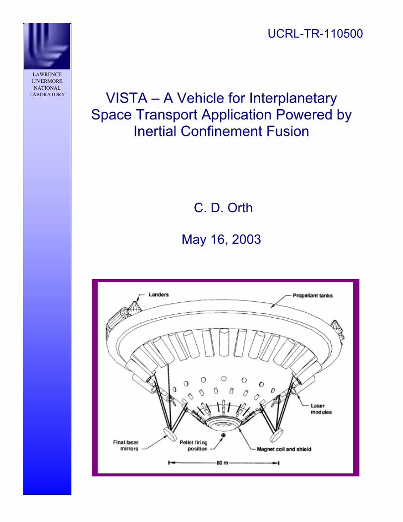
Our results include an entirely new spacecraft concept (Fig. I-1), which can bedescribed as follows. A 13-m-radius superconducting magnet generates a magnetic fieldthat has a peak field of about l2 Tesla and defines the boundaries of a thrust chamber. Pre-assembled marble-size fuel capsules are filled enroute with cryogenic deuterium (D) andtritium (T), which are isotopes of hydrogen. The fuel capsules surrounded by about 50 g ofadded hydrogen mass (called the expellant) are accelerated, injected, and positioned at thecenter of the thrust chamber at a repetition rate of 0 to 30 Hz, depending on the desiredthrottling (i.e., acceleration). Beams from a laser delivering about 5 MJ with an efficiency ofat least 6% are focused on the capsule, causing it to implode and release up to 7,500 MJ inneutron, x-ray, and plasma-debris energy. The conical spacecraft design permits nearly allof the neutron and x-ray energy to escape to space because the spacecraft structure lies inthe shadow of the thermal shield for the superconducting magnet coil. Only a small part(4%) of the emitted capsule energy strikes the shield protecting the superconducting coil,and must be radiated as waste heat or used in a Rankine power cycle. The crew quartersreside inside the propellant tanks at the outer lip of the conical structure, and are therebyshielded from cosmic radiations. Crew access is thereby slowly restricted as the missionproceeds because the consumption of propellant removes the shielding in those regions ofthe spacecraft lip that have been depleted of propellant. The entire structure can be rotatedabout its axis to provide artificial gravity (e.g., 3 rpm provides 1 gee at R = 100 m).
In the VISTA concept, the capsule debris, being conductive, expands spherically untilthe plasma pressure drops below the magnetic pressure. The debris is then deflected by themagnet, which stores an energy that is five times the debris kinetic energy. The debris,which is recombining and decreasing in conductivity, exits the thrust chamber in a limitedsolid angle, producing thrust and propelling the spacecraft with its blunt end forward. Bysimply changing the repetition rate, the ICF engine has variable thrust capability. Bychanging the amount of expellant mass surrounding each capsule (or by changing thecapsule design), the ICF engine has variable specific-impulse capability. We here assumethat the capsule gain (the ratio of the energy produced by the fusion to the driver energysupplied to the capsule) can be as large as 1500 for very advanced DT technology [see Sec.III.5, Eq. (4)]. Such gains allow the ICF engine to have a power/mass ratio of about 20 W/gat a repetition rate of 30 Hz. The avoidance of debris thermalization with surroundingstructures allows effective specific impulses (i.e., specific impulses multiplied by the square-root of the jet efficiency) near 20,000 seconds.

C. Orth, UCRL-LR-110500
8
Figure I-1: The VISTA Spacecraft Configuration. Two final laser focusing mirrors areshown, but optional configurations incorporate one or more mirrors.
The basic engine operation of VISTA is thus as follows. ICF capsules are injected intothe magnetic thrust chamber with the desired repetition rate and with the desired expellantmass per capsule. The capsule is tracked, and imploded using a 5-MJ laser. Depending onthe capsule design employed, the released energy is 200 to 1,500 times larger than the laserenergy. For the typical energy partition leaving the imploded capsule region, we estimatethat one-half of the fusion energy is in the form of high-energy neutrons, one-fourth in xrays, and one-fourth in charged plasma debris. VISTA uses only the plasma debris becauseonly the charged component is deflectable by the magnet—the rest of the energy is simplydiscarded. Typically 32% of the plasma energy is available for jet power as the plasma isredirected by the magnet into an exhaust plume. Consequently, VISTA uses only about 9%of the fusion output for propulsion. Another 5 to 10% of the plasma energy is extracted forpower generation. As mentioned above, the engine is throttled by changing the capsulerepetition rate. Specific impulse, which is set by the plasma temperature, is varied bychanging the capsule design or (more simply) by changing the expellant mass per capsule.

C. Orth, UCRL-LR-110500
9
Steerage of the entire spacecraft is accomplished by injection of the ICF capsules slightly offthe axis of the magnetic thrust chamber.
I.5 Intent and Overview of This ReportThis report describes the results of our systems analysis performed in 1986–1987, plus
the needed extensions and updates to enable the report to be complete enough to befoundational in establishing a realistic concept using fusion-powered space propulsion. Thereport is not meant to be exhaustive, and we have identified in the text where furtherstudies could be beneficial to validate certain scientific and/or engineering principles.
We first acquaint the reader with ICF and its use in the VISTA concept. We describethe power conversion and conditioning systems needed to operate the laser driver andauxiliary equipment. For power conversion, we consider both a Rankine thermal cycle andHyde's inductor pickup coil system. Radiators based on heat-pipe technology remove thewaste heat from the driver and power systems. One notable aspect of the conical design isthat the radiators (with appropriate mechanical stiffeners) actually form the conical surface.
We describe the capsule drivers currently under development for terrestrial ICFapplications, and explain the areas where further development is required beforeapplications to an inertial fusion rocket (IFR) are possible. We consider some advancedfusion fuels (DD and D3He), and show that it is not necessary to pursue a technologicaldevelopment path for an IFR that is different from the terrestrial ICF program because theadvanced fuels do not offer performance exceeding that for DT until extremely advancedtechnological levels are attained. However, there are advantages to using the advancedfuels, namely reduced tritium acquisition costs, reduced tritium hazards, and reducedhazards to personnel in other (nearby) spacecraft because of reduced neutron emissions.Therefore, because VISTA is capable of using any of these fuels, the development planwould begin with DT as the best choice for near-term missions, but would switch to DD forthe intermediate term, and to DD or perhaps D3He in the far term (provided an economicalsource of 3He can be developed).
With advanced DT technology, piloted-Mars missions can be conducted with a totalduration of about 145 days, including a stay on the planet of about 10 days. Roundtripmissions to Pluto will require a little more than 7 years, and roundtrip missions 2.5 timesfurther to 100 AU (1 AU = sun-Earth distance = 1.496x101 1 m) will require nearly 19 years. Inessence, for roundtrips, VISTA reaches coast speeds of 50 to 60 km/s for any destinationwithin the interplanetary system.
VISTA was not designed to go to more distant objects, but if it did, peak speeds wouldstill not exceed about 100 km/s. A roundtrip to 17,225 AU (the Oort Cloud) would thereforetake over 1,630 years! A roundtrip to the nearest star, Alpha Centauri (4 light years away,or about 250,000 AU), would take over 12,000 years! Although this performance isconsiderably better than that possible with either chemical, nuclear-electric (fission), or evenantimatter propulsion systems, it is rather clear that VISTA cannot be used to visit the starsand return within a human lifetime. It is possible, however, to go one-way to 104 AU in 20years, with extremely advanced technology (see Sec. XV.2).
C. Orth, UCRL-LR-110500
10
I.6 Comments on the Reality of ICFIt should be noted that we emphasize reality in this report. Because of the excitement
associated with space travel, many investigators have often introduced concepts for spacevehicles and power systems that seem to have attractive features, but the concepts arefound to suffer from one or more serious oversights after careful investigation is carriedout years later. We take the opposite approach in this report, and describe concepts thathave withstood a complete systems analysis. We therefore offer VISTA as a concept that webelieve is truly realistic. Our approach is significantly different than that taken by authorswho suggest concepts based only on conceptual ideas and/or trajectory analyses (e.g., the“rocket” equation).
Similarly, we use ICF based on the reality of the phenomena as proved both in theexplosion of thermonuclear weapons and in experiments in which underground nuclearexplosions in Nevada were used to generate x rays to drive ICF capsules. In particular,although it is not well known, Halite/Centurion experiments conducted at the U. S. NevadaTest Site using energy from underground explosions to implode an inertial fusion capsulehave already allowed the demonstration of excellent performance, putting to rest thefundamental questions about the basic feasibility to achieve high gain. In fact, the goodperformance in this series provides a new, higher level of confidence that it will indeed bepossible to design working laboratory capsules, such as those for the U. S. National IgnitionFacility (NIF).
It is therefore a misconception to believe that it might take decades to experimentallydemonstrate that ICF can serve as a source of power for space propulsion. This and othermisconceptions have led to many statements that have been published about ICF that aresimply not true today—for example, that capsule gains that would be large enough are“4 orders of magnitude beyond today’s capability,”18 that “an order of magnitude inspecific mass radiator performance is necessary,” and that ICF concepts employing DT “willbe unacceptable for long duration missions because of tritium’s short 12.3 year half life.”19
In addition, when people hear of fusion concepts, they usually think of magneticallyconfined fusion (MCF) and not ICF, presumably because of ICF’s past veil of secrecy andthe predominance in funding for MCF during past decades. However, as we stated above,ICF is already known to work with sufficient energy input. This statement cannot be madefor MCF or any other advanced propulsion concept except those based on fission. This doesnot mean that ICF is already fully developed—the truth is quite the contrary—but it doesmean that proof of principle for advanced technologies has been demonstrated only forICF. Thus, the view that ICF is merely a backup for MCF,20 although perhaps politicallyexpedient at the time the statement was made, is simply not a realistic perspective.
Consequently, the focus of terrestrial ICF efforts directed towards power productionis in reality not a proof of the viability of ICF in principle but a way to improve theeconomics of fusion power plants—that is, to determine whether ICF will be able to generatepower more cheaply than advanced fission reactors or coal/natural-gas-burning plants sothat utility companies will want to invest large amounts of capital to develop commercialfusion power. Terrestrial research is therefore attempting to determine the minimum driverenergy required with laboratory drivers, because the cost of electricity decreases with thesize of the fusion driver that initiates the fusion reactions. This effort to operate near theignition threshold places additional technical challenges on the field that are not directlyrelevant for VISTA, which operates well above any ignition threshold. Nevertheless, theseterrestrial efforts are important for VISTA for two reasons: (1) greater performance interms of higher capsule energy gain is required for really spectacular interplanetary transit

C. Orth, UCRL-LR-110500
11
times, and the methods to achieve such gains can presumably be developed at the lowerdriver energies applicable for terrestrial use; and (2) the best mission performance for spaceapplications does indeed require the smallest overall driver mass, because this reduces theso-called “dry mass” of the spacecraft. For these and other reasons, most terrestrial ICFR&D will automatically apply for space applications, but space applications will probablyrequire even higher capsule gains and even lower driver masses than terrestrial ICF R&Dmay want to pursue. Thus, to be able to use an IFR in the future, interest must be generatednow so that development plans can be formulated. Chapter XIV details our discussion ofthe technology readiness for VISTA.
Another item of reality concerns advanced fusion fuels. The emphasis on the use ofD3He fuel in some literature is in fact motivated by MCF requirements for high direct-thrust efficiency and the desire to reduce neutron shielding and radiator masses.21 On theother hand, ICF can use DT or DD or D3He fuels, although with increasingly moreadvanced requirements for capsule technology. Moreover, the use of matter-antimatterannihilation as a power source in the early 21st century is, at least as seen at this time,beyond the limits of practicality. This is not to say that these other “advanced-technology”systems might somehow be developed at some future date, but only that they are notviable for the near term—and ICF is.
Unless otherwise specified, we will use units as follows: energy in MJ, time in seconds,power in MW, length in meters, and mass in metric tons (one metric ton = 106 grams = 1tonne = 1 t).

C. Orth, UCRL-LR-110500
12
II. THE NATURE OF INERTIAL CONFINEMENT FUSION (ICF)
To describe the nature of fusion and how it can be applied to space propulsion, it ishelpful to begin with a description of fusion in the context of terrestrial fusion power-plantdevelopment. It is in this context that many people were introduced to fusion in the past.Unfortunately, because of the limited information that was available at that time, manyfalse notions arose concerning the readiness of the technology. The context we have chosenwill help clear up these misconceptions.
II.1 What is fusion?Fusion is the nuclear process by which nuclei lighter than iron (e.g., isotopes of
hydrogen) are forced to combine (fuse) to form heavier nuclei (such as helium) through aprocess that releases fast neutrons or protons. Fission, in contrast, is the nuclear process bywhich the nuclei of elements heavier than iron (e.g., uranium) are bombarded with slowneutrons to produce unstable isotopes, which then decay (break up) into lighter nucleithrough the process of radioactivity. Both fusion and fission release energy through thewell-known Einstein equation E = mc2, because the combined mass of the products is lessthan the sum of the masses of the starting nuclei—hence, mass has been converted intoenergy.
One difference between fusion and fission is that fusion releases about four timesmore energy per unit mass, so fusion is preferred from an energetics standpoint. Fusionalso involves less radioactivity because, unlike fission, the process itself is not inherentlyradioactive, and any induced radioactivity (e.g., from neutron emissions activating nearbystructures) can be kept to a minimum by the use of so-called low-activation materials.Fusion is also not subject to explosion (as at Chernobyl). Fusion is also not subject to the“China syndrome” (where the uranium fission fuel can melt down through its containmentif emergency cooling fails) because light elements do not have the high heat contents typicalof the heavy elements used in fission reactors. In addition, light elements have lower decayheats than the fission products produced in fission reactors. Fusion thus offers manyadvantages over fission.
The drawback for fusion has been the difficulty in developing the technology.Because the nuclei that are fused together in a fusion reaction are all positively charged,high temperatures (about 10 keV, or about 100 million degrees Kelvin) are required toovercome what is called the Coulomb (repulsive) barrier and get the nuclei close enough sothat they can “stick” (fuse) together. Such high temperatures are achieved by heating thefuel in some way (e.g., by compression) so that the product of fuel density and theconfinement time nτ can exceed 101 4 s/cm3 (the Lawson criterion). Only then will thecharged byproducts of the reactions deposit their energies in the fuel and “bootstrap” thetemperature up to the required level. At such high temperatures, the fusion fuel cannot becontained by ordinary mechanical vessels, which would melt, so the fuel is confined eithermagnetically or inertially. Magnetic confinement (such as in a Tokamak) involves a low-density gaseous fuel (plasma) confined by heavy external magnets (n ~ 101 4/cm3), soseconds or more of confinement are needed to satisfy the Lawson criterion; inertialconfinement involves densities nearly a thousand times liquid hydrogen densities (i.e., 200to 300 g/cm3 or n ~ 6x10² 5/cm3), so it requires confinement times of ~2x10–12 second. Thedifferent types of fusion are therefore designated by the type of confinement: inertialconfinement fusion (ICF), which is also called inertial fusion, and magnet confinement

C. Orth, UCRL-LR-110500
13
fusion (MCF). Fusion is also known to occur in the center of the sun, where gravitationprovides the confinement and the high temperatures.
II.2 What is inertial fusion?For inertial fusion, a capsule is prepared that is essentially a spherical “fuel” shell of
hydrogen isotopes surrounded by what is called an ablator (i.e., a layer that can be burnedaway). Such a capsule is irradiated with beams of energy from a “driver.” If the irradiationis directly on the capsule, the type of drive is said to be “direct drive.” If the driver beamsare focused into a small metallic cylinder (a “hohlraum” [German: empty room]) that heatsup and irradiates the capsule with x rays, the type of drive is said to be “indirect drive,” andthe hohlraum with the capsule mounted inside are said to be the “target.”
The driver beams (or the x rays) heat up the surface of the ablator to such anenormous temperature that the surface material blows off radially at great speed. Becausefor every (momentum) action there is a (momentum) reaction, the blow off causes aninward compression (implosion) of the capsule. As the capsule implodes, the density andtemperature at its center increase to the point at which the fusion reactions begin (i.e., thefuel “ignites”). At this time, the inward-moving fuel is confined by its own inertia, becausethe inward-moving fuel tends to continue moving inward. This explains why this type offusion goes by the name inertial confinement fusion (ICF).
As the fusion fuel “burns,” the nuclei fuse together and release energy in the form of xrays and fast (14-MeV) neutrons as well as particulate kinetic energy (the energy of thevaporized target materials) that is referred to as plasma debris. This sudden release ofenergy stops the implosion, and reverses it to form a miniature explosion that blows thematerial apart. This disassembly of the fuel limits the fusion burn, as does the depletion ofthe D and T constituents as they are consumed, so that typically only about 1/3 of thefusion fuel actually fuses (i.e., the burn efficiency is ~1/3).
For a terrestrial power-plant application, an ICF capsule is about the size of a marble,and its energy release is about 1/4 ton of TNT equivalent. Such explosion sequences arerepeated at the rate of about 5 to 10 targets every second. The energy from such explosionsis collected as heat in the wall of a spherical fusion chamber that contains the explosions.This heat can be used to operate a power plant with a steam turbine in much the same wayas a coal-fired plant. A fusion plant is hence very similar to a regular power plant, exceptthat a fusion plant needs (1) a driver to generate beams of energy to compress the fusionfuel to the required conditions, and (2) a fusion chamber.
It is noteworthy that inertial fusion will work with different fuels. The simplest fusionreaction, and the one which is the easiest to initiate (because it has the highest cross section),is the combination of one deuterium (D) nucleus with one tritium (T) nucleus to make onehelium nucleus (α particle) plus an energetic (14.1 MeV) neutron. This reaction is referred toas DT fusion, and is written as follows:
D + T = n(14.1 MeV) + α(3.5 MeV) (1)
Deuterium is a heavy form of hydrogen (with one extra neutron in its nucleus), and tritiumis a heavier form of hydrogen (with two extra neutrons). The DT reaction releases 17.6 MeVper interaction, or 339 MJ per mg of DT (at 100% burnup). Only about 1/4 of the totalenergy released appears as kinetic energy of charged particles (see Sec. III.6). Althoughtritium is somewhat radioactive, and hence DT fuel is somewhat radioactive, the nextgeneration of inertial fusion could use just deuterium (DD). This type of fuel has about the
C. Orth, UCRL-LR-110500
14
same energy output, is not radioactive, and can be extracted from (sea) water at the rate ofabout 1/15 gram per gallon (i.e., enough for 1 or 2 capsules); one gallon hence has thereleasable energy content of 1.8 tons of TNT equivalent (at 1/3 burn-up). The vastness ofthe oceans therefore provides an essentially inexhaustible supply of fusion fuel. Thedisadvantage of DD fuel is that it is harder to ignite, requiring about 3 times the ignitiontemperature (and hence a larger driver, and a different target design).There are also moreadvanced forms of fusion, such as D3He (cf. Sec. III.7).
The advantages of fusion (and ICF in particular) arise from its huge release of energy.It is this high specific energy output that enables ICF to have power/mass ratios from tento several hundred watts per gram. The huge energy release enables the fuel and asurrounding mass of expellant to reach very high temperatures (typically near 1 keV, or11,600,000 K). These high temperatures produce particle speeds of typically 3 × 10⁵ m/s,and hence specific impulses in the tens of thousands of seconds. No other viable technologycan produce both high power/mass ratios and high specific impulses. For example, a highpower/mass fission rocket may only produce a specific impulse of one to two thousandseconds.
In DT fusion Eq. (1), 80% (14.1 MeV) of the total energy release (17.6 MeV) resides inthe neutrons, upon their creation. The remaining energy (3.5 MeV) resides in the alphaparticles (4He nuclei). The ranges of the alpha particles are generally shorter than the size ofthe compressed capsule, so all alpha energy is deposited in the fuel. This deposition"bootstraps" the fuel to higher temperatures and higher fusion rates. Most, but not all, ofthe neutrons escape. In fact, assuming that the column density of a compressed fuel capsulemust be at least a few g/cm2, only about 60 to 70% of the total energy escapes the capsulein neutron energy. More neutrons are captured when expellant is added, especiallyhydrogen, which has a short neutron interaction mean free path (4.0 g/cm2). Perhaps only50 to 55% of the total energy will then escape from the capsule-expellant region. A smallfraction (4%) of these neutrons strike VISTA's magnet coil shield and contribute to vehiclewaste heat. The rest of the neutrons travel away from the original location of the capsuleisotropically out into space at about 1/6 the speed of light.
The other half of the fusion energy is divided between x-rays and the plasma debris(cf. Sec. III.6). The x-rays are of course radiated away in the same manner as the neutrons,while the plasma thermal energy is converted into radial kinetic energy of the expellantions as the expellant expands from the vicinity of the hot capsule. Put simply, the capsulemicroexplosion heats the expellant, and all of the mass expands, emitting x rays in theprocess. By the time the debris has expanded more than one meter, its internal temperatureis near 1 eV (i.e., cold), so it stops radiating. The debris radial kinetic energy is still near 1/2to 1 keV, however, even though the plasma temperature is cold. Very crudely, if E is theenergy trapped in a debris mass m, then the final average debris velocity is approximately(2E/m)1/2. It is this high velocity, which basically reflects the original material temperatureprior to expansion, that allows VISTA to have high specific impulse.
II.3 The Advantages of ICFAt this time, ICF has many advantages over MCF. First, ICF is now known to work
with sufficient energy input, as explained in Section I.6. Basic scientific feasibility is thereforeno longer an issue in principle for ICF, with sufficient energy input.
Second, DT fusion produces fast neutrons whose energy content can becollected—and the environment (e.g., crew quarters) shielded from induced

C. Orth, UCRL-LR-110500
15
radioactivity—only by the introduction of shielding. For ICF, this shielding is minimalbecause the source of the neutrons is essentially a point (the center of the implodedcapsule). The shielding for a terrestrial plant can therefore be placed around the exteriorwall of the fusion chamber as a spherical shell, and can even be designed to serve both asshielding and as (or in conjunction with) an absorber of neutron energy for the transfer ofheat energy to a heat exchanger. For MCF, however, the source of the neutrons is a largeextended source (e.g., the entire doughnut-shaped interior cavity of a tokamak).Consequently, the geometry of the shielding for MCF cannot be a spherical shell, soconsiderably more shielding is required. Third, because of the low-density nature of theMCF fuel, and the large amount of shielding required, a power plant utilizing MCF is muchlarger and hence more expensive (and more massive) than we think a power plant utilizingICF will be.
Fourth, ICF has greater physical separability between the location of the fusionreactions and the emplacement of the high-technology equipment that energizes the fusionfuel. Fifth, ICF offers a clearer approach to maintenance—continuous beam maintenancemay even be feasible by including extra driver beams. Sixth, ICF offers more control,because one driver can feed multiple fusion chambers, and variable repetition rate can beemployed. Seventh, ICF has an attractive and shorter development path at lower cost (seeSec. XIV.3).
II.4 Why don’t we have a terrestrial ICF power plant now?Before utility companies will become interested in inertial fusion energy (IFE)—that
is, to make energy in a power plant based on ICF—we must demonstrate that IFE can beeconomically feasible. The main problem for IFE (and fusion in general), other than thecomplex nature of the technology itself, is the great difficulty in designing a power plantthat has a low enough construction cost to permit economic feasibility. The reason for this isthat an IFE plant includes extra systems that a fossil-fuel plant does not have, namely, adriver and a fusion chamber. These systems are in addition to the thermal (steam-turbinebalance-of-plant) equipment that is common to IFE as well as to other types of powerplants. Because the fuel costs for IFE should be almost negligible, the combined cost of thedriver and the fusion chamber for IFE must be compared with the cost of the boiler in afossil-fuel plant and the operational cost of securing fossil fuel. Such a comparison indicatesthat IFE must demonstrate economic feasibility by designing a driver and a fusion chamberthat are low enough in cost.
The size, and therefore the cost, of a fusion chamber is dependent primarily on theplant’s thermal power, and only weakly dependent on the energy that the driver beamsmust focus on the target. In contrast, the cost of the driver is highly dependent on thedelivered energy (cost ~ Edr
1/3). Thus, for a given size of power plant, the economiccompetitiveness of IFE depends on whether the technology will function reliably at theminimum driver energy. The amount of driver energy required is in turn determined bythe target gain (i.e., the ratio of the energy produced by the target and the energy deliveredto the target by the driver beams). One key to the economic feasibility of IFE is thereforethe ability to operate ICF as close to its ignition threshold as is possible and still maintainreliability. Such operation introduces significant technological challenges in finding thetarget design that will produce a high-enough energy gain (>100) at a small-enough driverenergy (1 to 2 megajoules) when target gain tends to increase for a given type of targetroughly as the 1/3 power of the driver energy (G ~ Edr
1/3). Said differently, we can achieve alarger target gain if we use a larger driver, but economics (and dry-mass constraints forspace applications) require minimum driver size.

C. Orth, UCRL-LR-110500
16
The lack of sufficient target gain has made another issue become a key to theeconomic feasibility of IFE. This secondary key is the scientific feasibility of using alaboratory driver to energize an available type of target. Targets requiring more energyrequire a larger driver, which is more difficult to develop because of the technologicalconstraints in generating more energy in temporally shaped spatially smooth beams and indelivering this energy efficiently to a target. Because the most reliable target designs delivercalculated gains significantly less than 100 for small driver energies, a larger (~2 megajoule)driver had to be developed. It is the difficulties with the technological challenges dealingwith target gain and the feasibility of the required driver that have constrained the earlydevelopment of IFE.
II.5 Why Consider Fusion for Space Propulsion Systems?We have seen that ICF as used by VISTA uses only about 1/4 of the emitted fusion
energy, discarding 3/4 of the energy in the form of neutrons and x rays and utilizing onlythe charged debris plasma in the magnetic thrust chamber. This inefficiency of 1/4 wouldappear to exactly cancel fusion’s inherent advantage of a factor of 4 relative to fission inconverting mass into energy by E = mc2 (see Table II-1). Fission can of course be used in thenear term because it is a developed technology and fusion is not, but once fusion isdeveloped, what then? Would fission and fusion be on an equal footing for spaceapplications? No, they would not, because fusion produces high-quality emissions that aredirectly usable in high mass-flow-rate propulsion systems, and fission and antimatter-annihilation concepts do not. Let’s examine why this is so.
In practice, one must be able to use the energy emitted by the process beingconsidered, and it is here that fusion is far better than any of the other power sources,including antimatter-matter annihilation. The reason for this is that, at high exhaust-massflow rates, all of the other power sources require containment vessels to convert theemitted particle energy into a useable form to produce thrust in one direction, and thematerial temperature constraints to avoid melting the containment vessel constrain eitherthe power/mass ratio or the specific impulse or both.
Chemical reactions, although they afford high power/mass ratios (101 to 103 W/g),occur at inherently “low” temperatures, thereby producing low specific impulses (less thanabout 103 s). Fission reactions release high-energy neutrons and gamma rays, but theymust travel through centimeters of material before interacting and delivering their energiesto produce heat; the fission rocket thereby has high power/mass ratios (101 to 102 W/g)but only moderate specific impulses (less than several thousand seconds), while nuclear-electric propulsion (NEP) systems have high specific impulses (103 to 105 s) but onlymoderate power/mass ratios (less than 1 W/g). Fusion, on the other hand, emits a high-speed debris plasma that is directable with a magnetic field, thereby allowing the inherentlyhigh (~1 keV) temperatures of the emitted particles to be directly converted into exhaustvelocities without changing the particle speeds. Antimatter annihilation has such long-rangereaction products that the use of appropriate expellant is impractical without exceeding thedynamical limits of the system (magnet) that redirects the products into an exhaust. Thus,only fusion allows both high power/mass ratios (101 to 103 W/g) and high specific impulses(103 to 106 s).

C. Orth, UCRL-LR-110500
17
Table II-1 Attributes of Various Power Sources
Power Source Total Efficiency ForConverting Mass
Into Energy
Emitted Particle Range in Materials
Chemical reactions Approx. 10–10 Light AngstromsFission reactions 0.0009 Neutrons
Gamma rayscmcm
Fusion reactions 0.0038 X raysNeutronsDebris plasma
µmcmDirectable with a magnet
Antimatter-matter annihilation
1.000 PionsGamma rays
cmcm
ICF is even expected to outperform MCF if ICF can achieve a low driver mass because(1) MCF uses a large volume of fuel, unlike ICF’s point source, so large shielding masses arerequired to avoid neutron irradiation of spacecraft components and the crew; and (2) MCFincorporates high magnet masses at high engine power levels. Thus, it is a good guess thatICF systems (10–20 W/g) will probably outperform the MCF systems (1–10 W/g).22
Consequently, an ICF-powered spacecraft like VISTA is probably the fusion configurationwith the best performance of any fusion system, and certainly the best system amongpractical non-fusion configurations for 21st -century interplanetary missions. Some of thereasons why NASA could consider fusion for its advanced planning have already beendocumented.23 Other MCF and ICF comparisons are described in section XVI.
II.6 Advanced ICF target conceptsWe assume that capsule gains of 300 to 2000 must arise through advanced highly
speculative target concepts such as the fast ignitor.24 This concept employs capsulecompression less sophisticated than that for a normal target, followed by a ~200-ps 101 8
W/cm2 laser pulse to burn through the ablated material vaporized by the compressionaldriver beams and create a “channel” to the fuel core. Ignition is accomplished with a ~30-ps102 0 W/cm2 laser pulse directed through the channel. Such a concept holds the promise oftarget gains in the 500 to 1000 range, and perhaps higher, because less energy is used incompression of capsule material. Other concepts may be required to get gains well above1000.
C. Orth, UCRL-LR-110500
18
III. TARGET SYSTEMS
The term target refers to the entire laser target assembly including the capsule itself,the hohlraum (if present), and any surrounding expellant mass. We use the term target andnot “pellet” because the whole assembly is specifically the target that a laser driver must“hit.” The term capsule refers only to the spherical combination of the fusion fuel and otherlayers integrally attached to the fuel layer. The term propellant includes the fusion fuel (DT)and other target fluids (including the expellant placed around the hohlraum).
III.1 Capsule DesignThe optimum design of a target, as we envision it for VISTA, includes a capsule driven
indirectly with x rays—that is, the target includes a high-gain capsule placed inside ahohlraum, which is in turn placed inside the expellant. Laser beams directed into thehohlraum through holes in the expellant create x rays, which implode the capsule throughintense vaporization (ablation) of its outer surface (that's why the outer capsule layer iscalled the ablator). A generic type of hohlraum target thus looks like the following:
Figure III-1: A Generic Type of Target for Indirect Drive
Indirect drive is preferred over direct drive for VISTA application because direct drivewould require symmetrical illumination of a capsule, and hence many final-opticmirrors—not just the one or two needed for indirect drive as shown in Fig. I-1.
Because it is important for target assembly, handling, and tankage to have some ideaof the overall concepts in ICF capsule design, we describe here some of the general featuresof capsules that might be used for VISTA. The canonical design of a high-gain capsule iscomposed of a cryogenic shell of DT fuel surrounded by some sort of ablator material, witha small amount of DT gas in the center. The DT fuel and the ablator material are both intheir cryogenic states wicked into foam substrates or equivalent. 25 The ablator material canin fact be hydrogen seeded with higher-Z contaminants. The amount of gas in the centralvolume depends on the equilibrium vapor pressure of the DT at the fielded temperature,and is therefore variable. This gas pocket serves as an ignitor for the capsule, because whenthe capsule is imploded, the DT gas is the first fuel to ignite. A burn front can thenpropagate throughout the remaining fuel region.
Hohlraum
Laser beams
Capsule
C. Orth, UCRL-LR-110500
19
Operation of a target is as follows. First, x rays created inside the hohlraum by thelaser beams ablate the out capsule layer. This ablation creates an inward force that implodesthe fuel shell and compresses the central gas volume. The gas, being of lower density,reaches a much higher temperature than the fuel shell. The higher temperature indicates agreater heat content per unit mass, but because there is so little gas, the total energyconcentrated in the gas is very small. Nevertheless, the higher gas temperature causes amuch higher fusion rate, so the gas serves as an ignitor (hotspot) for the main fuel. Byconcentrating the compressional energy in the gas and not in the main fuel, a smaller lasersystem is required for the same fusion yield, thus permitting a more efficient implosion (i.e.,higher gain: see Sec. III.5).
The maximum capsule output in VISTA is 7,500 MJ, assuming an arbitrary capsule gainof 1,500 with a 5-MJ driver (cf. Sec. III.5, Eq. 4). This release is equivalent to that of 1.8 tonsof TNT, which is about eight times larger than that from the capsule envisioned forterrestrial ICF power plants. Because DT fusion releases 339 MJ/mg, about 66 mg of DT areneeded to produce 7,500 MJ of fusion output if the fusion burn efficiency is 33%, but only 46mg of DT is required for a burn efficiency of 47.6% (which is assumed here for acompressed fuel column density of 5 g/cm2). Because DT is 60% tritium by mass, eachcapsule therefore contains at least 28 mg of tritium. Peak engine operation at 30 Hz willthus consume at least 120 kg/day of DT and 72 kg/day of tritium. The fuel and hohlraummasses, however, are essentially negligible in comparison with the typical expellant mass of50 grams per target.
III.2 ExpellantHydrogen has the highest probability for scattering a fusion neutron to absorb energy
and increase the debris kinetic energy (and hence the specific impulse). The mean free pathfor neutron energy attenuation in hydrogen is only 4.0 g/cm2. Hydrogen can also bestored, transported, and loaded in a capsule all in its liquid state. A cryogenic expellant can,in fact, be held firmly by capillary forces in spherical shells of plastic foam.26 Liquidhydrogen expellant also permits changing the mass of expellant for each target during themission, if the need should arise.
We shall therefore assume that the expellant is hydrogen. Nevertheless, hydrogen hasdisadvantages. For example, its low density of 0.077 g/cm3 causes the targets to have avery large size, which complicates the design of the target injection system. In addition,hydrogen debris plasma tends to be less conductive than higher-Z expellants, thusexacerbating plasma decoupling in the plume, which can lower jet efficiency (see Sec. V.5).Moreover, tankage is at least twice as large for a fluid than for a solid, and it may be difficultto configure a liquid so it has holes for the driver beams to pass through to reach thehohlraum.
We, therefore, expect that it is quite likely that the expellant will have to be moderate-Z to high-Z, especially to obtain maximal jet efficiency. For VISTA, most any type ofexpellant can be used, if it can be stored, and later loaded around a target. If solid expellantsare considered, we suggest merely using more massive hohlraums.
A more advanced consideration is whether the expellant should be spatially shaped toreduced neutron emissions in particular directions (e.g., toward spacecraft components, inorder to reduce the need for neutron shielding). Although we left evaluation of this subject

C. Orth, UCRL-LR-110500
20
to a future study, Sahin et al.27 have since verified that such spatial shaping can reduceneutron irradiation of spacecraft components by factors up to about 12.5.
III.3 Target Fabrication and AssemblyWe envision that all of the hohlraums and capsules for a mission will have been pre-
fabricated and pre-assembled prior to the mission, and stored onboard without their fillingsof cryogenic fluids. This need not be the case, however, because fabrication in a onboardtarget factory is not only possible, but may have its advantages. For example, onboardfabrication could improve sphericity due to the long periods of reduced gravity (e.g., nearthe rotation axis), and would eliminate shipping and storage damage to the capsuleassemblies. A foam substrate, if used for hydrogen expellant, will most likely bemanufactured onboard due to the otherwise large volume required for capsule storage (cf.Sec. III.8).
Because the use of wetted foams is a relatively new technology, more development isrequired before final decisions can be made regarding the best place and methods ofcapsule fabrication. Nevertheless, we envision the use of automated fabrication techniquesfor all capsule materials patterned after those conceptualized and parameterized for thefabrication and electrostatic transport of laboratory glass-sphere targets.28 More researchon this topic is definitely in order.
Once any final assembly is completed, if required, the DT fuel, hydrogen ablator, andhydrogen expellant will be wicked into their substrates immediately prior to use. Fromthen on, the capsules must be kept cold (at about 20 K). The size of each filled targetassembly will be roughly the size of the liquid hydrogen expellant (density 0.077 g/cm3);for a 50-g expellant, the target diameter will be about 12 cm, which is the size of a largegrapefruit.
III.4 Target Acceleration, Injection, Tracking, and Beam PointingDetailed analyses have not been conducted for the explicit systems needed for target
acceleration, injection, and tracking for an IFR. However, many of the general concepts fora terrestrial fusion power plant should be directly applicable. Some of the problemsassociated with target injection, tracking, and laser-beam pointing have been discussed byPetzoldt and Monsler.29 Differences between the terrestrial and IFR systems resultprimarily because 1) the IFR target (with its expellant) is much larger, and 2) the IFRreaction chamber ambient pressure (and temperature) is zero. The expellant makes it moredifficult to cool the fuel and remove the tritium radioactive-decay waste-heat generation of1/3 W/g. The removal of this waste heat to prevent boiling of the cryogenic liquids duringacceleration and injection is in fact the most crucial problem for the target systems. Moremassive targets are also harder to transport. On the other hand, the lack of an ambientchamber pressure reduces clearing times and target tracking errors for the IFR, and thesmall solid-angle subtended by spacecraft material as seen near the target-firing pointreduces thermal constraints during injection.
The acceleration and injection phases are limited by physical as well as the thermalconstraints. First, the minimum injection speed vinject is that which takes the target from theedge to the center of the thrust chamber (i.e., through a distance equal to the radius r of thechamber) in a time interval equal to roughly kn-1, where n is the IFR repetition rate in Hz

C. Orth, UCRL-LR-110500
21
and the k is the fraction of the interpulse period that is available for injection (i.e., thefractional time the chamber is clear of debris and vaporized material from the previouspulse). Typically, k is about 0.7 and r is about 15 meters. The minimum injection speed isthus vinject = rn/k, or 200-600 m/s depending on n. This speed assumes the use of arotating shutter or similar apparatus to block the target accelerator output port for 1–k =30% of the interpulse period, to allow for chamber clearing from the previous pulse, and toprotect the target accelerator from debris damage. Target injection speeds normally havean additional constraint arising from the requirement to keep the target cold as it traversesa hot terrestrial reaction chamber (e.g., a minimum of 300 m/s may be required for an 800K chamber30). In space, however, no such additional constraint is of great consequence.
A second constraint is that the acceleration of the target to vinject must not exceedamaxg, where amax is the maximum number of gee's the target can withstand and g = 9.8m/s2 is the acceleration due to gravity. That is, the acceleration time taccel must be at least(vinject/amaxg). For constant target acceleration, the required acceleration distance is thus atleast
saccel = (1/2)amaxgtaccel2 = (rn)2/(2amaxg). (2)
Suppose we assume amax = 10031 (wetted foam can withstand acceleration forces ofhundreds of gee's or more, due to the strong capillary forces). For a chamber of radius15 m, the minimum accelerator distance is hence 3 m at 5 Hz and 103 m at 30 Hz. Thisshows that the spacecraft in Fig. I-1 is large enough to accommodate a target acceleratorprovided the repetition rate does not exceed a few tens of Hz. Note that the time scale fortargets to traverse the accelerator may be much longer than the interval between fusionpulses. This merely requires targets to follow one another through the accelerator spaced atan interval tinject, several targets being in various stages of acceleration at any given instant.More modern studies32 have shown that a dual-membrane capsule support will permittarget accelerations well in excess of 103 m/s2, which would allow smaller accelerationdistances and higher repetition rates.
A cryogenic target will most likely not suffer thermal degradation during its transitthrough the thrust chamber, because the transit time is short and the effective temperatureof the environment (looking mostly out into space) is not much above 3 K. On the otherhand, the target must be protected during acceleration, so the accelerator channel must beat cryogenic temperatures. In addition, some mechanism must be included to extract the1/3 W/g tritium decay heat. The concept generally envisioned to satisfy both of theserequirements for terrestrial applications (without expellant) is to encase the target in athermal shield called a sabot. The sabot is designed with enough thermal capacity to absorbthe tritium decay heat, and in addition, to act as the bullet accelerated in a tight-fittingpneumatic barrel that adds rifling (rotation) to the exiting sabot for trajectory stabilization.In our application, such a sabot would have to be removed (by its own centrifugal force)before the target enters the thrust chamber, and be recycled, so that the sabots don'trepresent a mass loss. Alternately, it may be possible to coat the expellant with a thinmetallic layer, and let the expellant act as the sabot (which becomes very easy if theexpellant is iron). Perhaps a magnetic-induction accelerator could then be used instead ofthe pneumatic accelerator. More thermal calculations are needed like those done forterrestrial applications by Pitts33 to ensure that 30 mg of tritium can in fact be buried inside50 g of hydrogen (or iron) expellant. In addition, special precautions are needed in

C. Orth, UCRL-LR-110500
22
designing the outlet of the target injector, which is in direct line-of-sight to the target and,thus, susceptible to erosion from target emissions. A further complication for the spaceapplication is the location of the accelerator channel and/or sabot trajectory on the conicalspacecraft frame that itself constitutes radiators operating at high temperatures to expelwaste heat. In any case, to avoid unnecessary power consumption, future studies mustdetermine how the capsule can be cooled and placed inside some sort of thermal barrierwithout cooling a high-Z expellant to cryogenic temperatures.
The acceleration region is followed by a target coast region for several reasons. It ishere that sabots are removed, if they are used. A coarse target trajectory is determinedhere, and modified by electrostatic or inductive means to provide for corrections or vehiclesteerage. This trajectory offers an estimate of the position and time of arrival of the targetnear the center of the thrust chamber, where the laser beams must focus on the holes in theexpellant.
General tracking of the target can be accomplished by illumination with a CW laserand use of a tracking telescope to track a bright glint off the target. The best tracker systemuses the same optics as the main laser system, and is called a shared-aperture system.34
Such a system eliminates relative misalignment errors and vibrational jitter between thetracking and laser-pointing systems. Special features, yet unspecified, might have to beadded to the expellant exterior to track the holes in the target, if it proves infeasible todetect the physical holes in the otherwise smooth (metallic) expellant coating. This issuebecomes inconsequential, however, if the expellant is added by merely increasing thethickness of the hohlraum wall.
Laser-beam pointing will be accomplished by steering mirrors (deformable "rubber"mirrors are not needed because the chamber volume is not subject to turbulence, thermalboundary layers, ambient-gas breakdown, etc.). Because the final turning mirrors areunshielded against neutron damage, and because they are located in a region exposed to anx-ray fluence of about 0.4 MJ/m2, it might be better to steer the beams at the next upstreamoptical elements. X-ray protection of the final mirrors themselves can be avoided throughuse of special surface materials and placement far enough from the target. Use oftechniques being designed for terrestrial mirror protection (e.g., a puff of gas in front of themirrors for every pulse) cannot be employed without significant loss in jet efficiency, aswell as degradation in focusability and pointing accuracy (see Sec. IV.3).
III.5 Target Performance (Gain)The fusion release from a target is generally stated as the product of the energy
delivered by the laser driver (e.g., 5 MJ) and a quantity called the gain of the target. Thegain is defined as the ratio of the fusion energy produced by the target and the energysupplied to the target by the driver. Current DT technology permits target gains estimatedto be as large as 50 to 100 (see below), while very advanced technology may permit gainslarger than this by factors of at least 10. According to simple analytic models,35 the targetgain G for the most optimum target compression is a function of the laser driver energy Edr(in MJ) and the compressional efficiency εcomp:
G = c εcomp (εcomp Edr)n (3)

C. Orth, UCRL-LR-110500
23
For the Meyer-Ter-Vehn (MTV) Model, c = 6,000 and n = 0.3; for the Kidder Model, c =30,000 and n = 0.4. The MTV Model is the more conservative, and indicates gains about afactor of 6 less than the Kidder model. Use of polarized-DT fuel would increase the gain ineither model by a factor of (1.5) 0.9 = 1.4.36 Thus, for Edr = 5 MJ and maximumcompressional efficiencies (~0.2), G is expected to be between 1200 and 6000. Such highgains are speculative. Nevertheless, as an optimistic gain model based on both MTV andKidder, we shall assume the following relationship here
G = 877 Edr1/3 (4)
The exponent can vary from 0.3 to 0.4, while for hydrodynamic efficiencies varying from5% to 10%, the leading coefficient can vary from 100 to 300 for an exponent of 0.3, and from450 to 1200 for an exponent of 0.4. We hence chose a leading coefficient of 877 so Eq. (4)yields a gain of 1500 at 5 MJ.
Gains as high as those suggested by Eq. (4) are out of the question with near-termtechnology, but not with advanced technology. Near-term DT gains are better describedby37
G = (1300 Edr - 1040) 0.53 (5a)
or perhaps38
G = 16 Edr2/3 (5b)
Equation (5a) indicates a gain of only 96 for 5 MJ. For the fast ignitor (Sec. II.6), the gain for5 MJ is assumed to be about 760. according to a formula like the following: 39
G = 400 Edr0.4 (5c)
There is hence a range of technologies that should become available for ICF, manifested ingains from 100 for near-term technologies to about 1000 or more for advancedtechnologies.
We emphasize that the worth of ICF as a source of engine power is dependent on themagnitude of gain that is achieved in future target development. If the maximum gainsachieved are near 100, an IFR will not be competitive with other technologies. If themaximum gains achieved are anywhere near 1000, an IFR will probably outperform othertechnologies with ease. The target gain is hence the most important development item foran IFR. This is particularly true in light of the current laboratory gain achieved, which is lessthan 1. The NIF is expected to achieve gains of 10 to 20 for Edr = 1.8 MJ. Gains near or above1,000 thus represent a very large extrapolation from existing laboratory achievement, aswell as that expected near ignition threshold on the NIF.
The importance of target gain can be illustrated by examining the theoreticalmaximum yields (i.e., energy releases) available from targets of various DT fuel masses.Assuming that yield is equal to the product of fuel mass, 3.4 × 10⁵ MJ/g, and a burnefficiency of about one-third, we obtain the set of yields and gain values shown in Table III-1. Target yield is thus an indicator of the amount of fuel mass, but target gain for a givendriver input is an indicator of target technology.
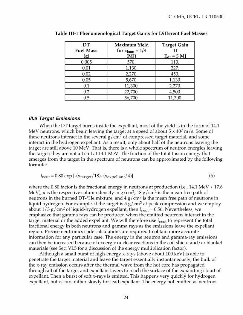
C. Orth, UCRL-LR-110500
24
Table III-1 Phenomenological Target Gains for Different Fuel Masses
DTFuel Mass
(g)
Maximum Yieldfor εburn = 1/3
(MJ)
Target GainIf
Edr = 5 MJ0.005 570. 113.0.01 1,130. 227.0.02 2,270. 450.0.05 5,670. 1,130.0.1 11,300. 2,270.0.2 22,700. 4,500.0.5 56,700. 11,300.
III.6 Target EmissionsWhen the DT target burns inside the expellant, most of the yield is in the form of 14.1
MeV neutrons, which begin leaving the target at a speed of about 5 × 10⁷ m/s. Some ofthese neutrons interact in the several g/cm2 of compressed target material, and someinteract in the hydrogen expellant. As a result, only about half of the neutrons leaving thetarget are still above 10 MeV. That is, there is a whole spectrum of neutron energies leavingthe target; they are not all still at 14.1 MeV. The fraction of the total fusion energy thatemerges from the target in the spectrum of neutrons can be approximated by the followingformula:
fneut = 0.80 exp [-(xtarget/18)- (xexpellant/4)] (6)
where the 0.80 factor is the fractional energy in neutrons at production (i.e., 14.1 MeV / 17.6MeV), x is the respective column density in g/cm2, 18 g/cm2 is the mean free path ofneutrons in the burned DT-4He mixture, and 4 g/cm2 is the mean free path of neutrons inliquid hydrogen. For example, if the target is 5 g/cm2 at peak compression and we employabout 1/3 g/cm2 of liquid-hydrogen expellant, then fneut = 0.56. Nevertheless, weemphasize that gamma rays can be produced when the emitted neutrons interact in thetarget material or the added expellant. We will therefore use fneut to represent the totalfractional energy in both neutrons and gamma rays as the emissions leave the expellantregion. Precise neutronics code calculations are required to obtain more accurateinformation for any particular case. The energy in the neutron and gamma-ray emissionscan then be increased because of exoergic nuclear reactions in the coil shield and/or blanketmaterials (see Sec. VI.5 for a discussion of the energy multiplication factor).
Although a small burst of high-energy x-rays (above about 100 keV) is able topenetrate the target material and leave the target essentially instantaneously, the bulk ofthe x-ray emission occurs after the thermal wave from the hot core has propagatedthrough all of the target and expellant layers to reach the surface of the expanding cloud ofexpellant. Then a burst of soft x-rays is emitted. This happens very quickly for hydrogenexpellant, but occurs rather slowly for lead expellant. The energy not emitted as neutrons

C. Orth, UCRL-LR-110500
25
or x-rays remains in the plasma debris, and ends up as kinetic energy of the debris ions(which are mostly expellant ions, not target ions).
For scaling purposes, it is necessary for us to have relationships for the fractions of thetotal fusion energy that ends up in the form of x-rays and debris, fx-ray and fdebris, as wechange the mass of the expellant. These fractions will obviously change with the densityand mass of the expellant. Unfortunately, however, the complex hydrodynamicphenomena associated with the explosion makes it very difficult to make an analyticcalculation of these emission fractions. One might guess that the fractional energies in x raysand debris are divided roughly equally, with half in x-rays and half in debris, with a spreadthat varies from ~25% to ~75% for the expellant masses and densities of interest here. Wetherefore chose the following empirical formula to specify the debris fraction:
fdebris = (1–fneut) [0.25 + 0.50 (1–exp {–(1/15) mexpellant sqrt(ρexpellant)})] (7)
where the expellant mass mexpellant is in grams and the expellant density ρexpellant is ing/cm3. We then have
fx-ray = 1 – fneut – fdebris – floss (8)
where floss is the fractional loss in coupling laser energy to x rays contained by thehohlraum, which we will arbitrarily assume to be of order 7%. For example, for 50 g ofexpellant at density 0.077 g/cm3 wicked into a foam shell of inner radius 1 cm, 56% of thefusion energy is in neutrons (not 80%), 24% is in charged-particle debris plasma (not 20%),and 20% is in x-rays. Thus 24% of the energy is directable by a magnetic field.
III.7 Advanced FuelsThe only advanced fuels that we consider here are DD and D3He. We will not consider
p1 1B, or other more exotic fuels because the Edr required to achieve ignition is much toolarge to make these fuels practical for space propulsion unless DT hotspots or otherconcepts can be employed, all of which is beyond the scope of this report.
III.7.1 DD FuelComplete DD fusion is specified by two primary reactions,
D + D = 3He (0.82 MeV) + n (2.45 MeV) (9a)D + D = T (1.01 MeV) + p (3.02 MeV) (9b)
plus two secondary (catalyzed) reactions,
T + D = 4He (3.5 MeV) + n (14.1 MeV) (10a) 3He + D = 4He (3.6 MeV) + p (14.7 MeV) (10b)
(The reaction n + 3He = p + T is not expected to be significant.) Assuming the produced Tand 3He also burn, the net result is thus

C. Orth, UCRL-LR-110500
26
6D = 2 (4He) + 2n + 2p + 43.3 MeV (11)
That is, per binary DD reaction, 14.4 MeV are released per interaction, or 347 MJ permg of DD (assuming 100% burn up). The energy release per mg is thus comparable to DTfusion (339 MJ/mg). For DD fusion, however, 61.7% of the total energy ends up in chargedparticles at each reaction site, instead of the 20% for DT, and 38.3% of the total energy is inneutron kinetic energy. That is, the range of a 3 MeV proton in H2 is 0.006 g/cm2, while therange of a 14.7 MeV proton is 0.108 g/cm2, so in DD, which has the same number ofelectrons but twice the mass, the respective ranges ought to be roughly twice these values(because the energy loss is based on the electrons with which the proton would interact).Thus, only the neutrons from the DD reactions escape a target with a compressed columndensity of 3 to 5 g/cm2. In fact, even some of the neutrons interact in this amount ofmaterial (as per Eq. 6), so the fractional energy into charged-particle debris arising from theheated fuel and expellant actually starts at a value somewhat higher than 61.7% (~74%).Some of this energy (perhaps half) is then radiated from the plasma as x rays. The exactenergy remaining in the charged debris plasma (i.e., the amount redirectable by a magneticthrust chamber) depends on the target design and the amount of expellant around thecapsule. As a rough approximation, we will use Eqs. (6) and (7) here, which indicate that~26% of the total energy emerges as neutron kinetic energy, ~37% emerges as x rays, and~37% emerges as charged debris plasma kinetic energy, the latter being only 1.5 times thefraction attainable from DT.
It is interesting to note that the DD cross sections for Eq. (9) are one and one-halfdecades smaller at a burn temperature of 100 keV than the cross section for DT, and aboutone decade smaller than that for D3He. The DT cross section peaks at ~70 keV and the D3Hecross section peaks at ~300 keV, but the DD cross section peaks well above 1 MeV.Consequently, DD fuel burns only weakly at ICF scales, because the burn temperature istypically less than 100 keV. The DD legs (Eq. 9) thus burn sluggishly, then when some T or3He is made, Eq. 10 proceeds more rapidly, providing most of the yield. The importantpoint is that all of the reactions in Eqs. 9 and 10 proceed, so we indeed expect the neutronenergy fraction to be roughly 26%, as indicated by these equations (or perhaps slightly lesswhen we consider the neutrons that interact before they leave the compressed fuel and theexpellant).
In order to ignite DD (or any) fusion fuel, a driver must be used to hydrodynamicallycompress the capsule so the fuel temperature is raised to the temperature at which thefusion rate per gram is just larger than the electron bremsstrahlung loss rate per gram.Above this minimum fuel temperature, the ionizational energy losses of the charged fusionproducts can bootstrap the fuel to higher temperatures and produce what is called"runaway burn," which is what is meant by fusion burn. The minimum temperature for DTis about 4.5 keV, but the minimum for DD is 16 keV, and the minimum for D3He is 38 keV.Moreover, most target designs are based on achieving temperatures at least 50% largerthan these minimums, to ensure reliable ignition. Unfortunately, it is somewhat impracticalto compress a fuel to temperatures much above 10 to 20 keV by normal means, so it is achallenge to ignite the advanced fuels by themselves, especially D3He. (It is also more of achallenge to ignite these advanced fuels with the fast ignitor concept described in Sec. II.6because the higher power requirement for the ignitor beam might make electrons of anenergy too high to deposit energy locally enough to produce the required high ignitiontemperatures.)

C. Orth, UCRL-LR-110500
27
For these reasons, all advanced fuels considered here will be assumed to have a core ofDT to act as a hotspot to ignite the advanced fuel. This core, if it is going to “trap” thecharged reaction products, must be at least one alpha-particle mean free path in radius atthe minimum burn temperature (i.e., 0.30 to 0.35 g/cm2). To promote higher burntemperatures and hence more vigorous burn, we shall instead use 0.5 g/cm2. In such a case,the fraction of the fuel mass that is tritium would be 0.2% of the total fuel mass if the totalcompressed fuel core column density is ~3 g/cm2, but only 0.04% if the total compressedfuel core column density is ~5 g/cm2. In either case, the hotspot burn temperature wouldbe about 70 keV (i.e., near the peak of the DT <σv> curve). Such a hotspot causes the DD toburn typically at ≤ 100 keV.
In any fusion reaction, only a fraction fburnup of the total fuel mass is able to burnbefore the target blows itself apart. This fraction, which is also called the burn efficiency,depends primarily on the column density xfuel of the compressed fuel in g/cm2, but also ona term Ψi dependent on the cross section at the burn temperature of the specific fuelutilized. A general expression, based on depletion of the needed ions, can be written as
fburnup = xfuel / (xfuel + Ψi) (12)
where Ψi is as follows:
1. DT: 5 to 6 g/cm2 at 70 to 80 keV (5 g/cm2 at 50 keV, rising to ~20 g/cm2 at 300 keV);2. DD: ~60 g/cm2 at 70 to 80 keV (~70 g/cm2 at 50 keV, falling to 50 g/cm2 at 100 keV,
falling to ~35 g/cm2 at 220 keV);3. D3He: ~50 g/cm2 at 70 keV (~70 g/cm2 at 50 keV, falling to ~39 g/cm2 at 100 keV,
falling to ~34 g/cm2 at 220 keV).In short, Ψi is ~5.5 g/cm2 for DT, ~60 g/cm2 for DD, and ~50 g/cm2 for D3He (unless theadvanced fuels can somehow be made to burn at temperatures well over 100 keV).Consequently, fburnup is roughly 35%, 4.8%, and 5.7% for DT, DD, and D3He (respectively)for a capsule with a compressed column density of 3 g/cm2, and 47.6%, 7.7%, and 9.1% for acapsule with a compressed column density of 5 g/cm2.
Target gain is equal to the product of the fuel mass, the burnup fraction fburnup,various ablation and hydrodynamic efficiencies, the fusion energy release per gram, and(1/Edr). Thus, for the same driver energy Edr, the same fuel mass, and the same xfuel, thetarget gain for DD is only about one-seventh to one-sixth that for DT, due to the differentburnup fractions, and the target gain for D3He is only about one-sixth to one-fifth that forDT. However, for an IFR with a magnetic thrust chamber, the important quantity is not thegain, but the product of the gain and fdebris, for it is the energy in charged debris plasmathat is converted into thrust by the magnetic field. If this Gfdebris product is normalized tounity for DT, it is 0.42 to 0.51 for DD without expellant, and only one percentage pointhigher with 50 g of expellant.
Consequently, DD produces about half of the exhaust energy that DT produces, at thesame mass flow rate, and hence a specific impulse only 70% of that for DT. However, use ofDD greatly reduces the tritium inventory, and also reduces the neutron emissions from 80%per reaction (~56% per target with expellant) down to 38% per reaction (~26% per targetwith expellant). We would therefore hope that there is the possibility of improving the DDtarget gain with creative ideas.

C. Orth, UCRL-LR-110500
28
III.7.2 D3He FuelThe D3He form of fusion,
D + 3He = α (3.6 MeV) + p (14.7 MeV) (13)
releases 18.3 MeV per interaction or 353 MJ per mg of D3He (assuming 100% burn up).Again, the total energy release per binary collision is about the same as for DT. Note,however, that 100% of the energy appears as kinetic energy of charged particles at eachreaction site—that is, the fuel is “aneutronic” at production. All of the emitted particles inEq. (13) deposit their energies inside a compressed fuel capsule having 3 to 5 g/cm2, so wemight expect this fuel to emit no neutrons and hence nothing but x rays and charged-particle plasma debris.
In actuality, however, some DD fusion will occur, even though the D3He cross sectionis somewhat larger than the DD cross section, so D3He is not aneutronic as applied to ICF.The situation is even worse when the D3He is ignited with a DT hotspot, because the 14.1-MeV neutrons from the DT hotspot convert some of the 3He and make tritium that canburn with the deuterium (n + 3He ---> p + T).40 Much of the yield then comes from the DTreactions. Even at large target sizes that achieve high burn temperatures, 10 to 40% of theplasma emission is in the form of x rays having more than 100 keV and hence rangessimilar to neutrons.41 The net result here is that perhaps ~40% of the energy of eachreaction ends up as neutron kinetic energy. When Eq. (6) is used to estimate the neutronenergy leaving the target (and expellant), we estimate that ~28% of the energy emerges inthe form of neutrons. Thus, D3He is definitely not aneutronic! The rest of the energy istypically split between x rays and the debris plasma, according to Eqs. (6) and (7), so about36% of the total energy is left to emerge as charged debris plasma kinetic energy, just as forDD fuel.
In the previous section, we showed that the burnup fraction for D3He is 5.7 to 9.1%respectively for compressed target column densities of 3 to 5 g/cm2. The Gfdebris product(i.e., the fractional energy into charged debris plasma kinetic energy) for D3He is henceonly 40 to 57% of that for DT, so the specific impulse at the same mass flow rate should beonly ~70% of that for DT, just as for DD.
For VISTA, we therefore see that D3He is not as good for an IFR as one might at firsthave thought. In fact, it appears to be about the same as DD in all performance aspects. Inaddition, D3He has two other distinct disadvantages for IFR applications: (1) there is nomajor source of 3He, so its use might necessitate mining the lunar surface and/or the Jovianatmosphere to obtain sufficient 3He, and perhaps even worse, (2) 3He has no convenientcryogenic phase that is commensurate with deuterium (deuterium freezes before 3Heliquefies, so the two substances tend to separate).42
III.7.3 General Comments about Advanced Fuels and AntimatterThe simplistic calculations presented in the previous two sections suggest that the
advanced fuels will not outperform DT, unless the burn temperature for these fuels can besignificantly increased. Furthermore, we have not discussed the possibility of seeding thesefuels with tritium, which greatly increases their yields. We leave to further studies just howone might optimize the performance with advanced fuels.

C. Orth, UCRL-LR-110500
29
Antimatter fuels are not considered to be a serious option for VISTA for manyreasons. As we demonstrate in Section XV, the performance with antimatter is verydiscouraging because the antimatter-matter annihilation produces pions and gamma raysthat do not readily interact with matter because of their long mean free paths in both thefuel and the expellant. Consequently, antimatter-matter annihilations produce little chargedplasma debris that is usable in VISTA’s magnetic thrust chamber, and the charged-pionproducts themselves have energies that are much too large to be efficiently redirected by amagnetic field of any practical strength. Antimatter is also very difficult and costly toproduce and store, let alone transport, although some advances are being made. Still, thecost of producing antimatter is enormous in comparison to the rather expensive cost oftritium, and without further innovation, similar masses of tritium and antimatter would berequired for VISTA (see Sec. XV). Thus, were it not for the discouraging performance withantimatter, its cost would still be prohibitive enough to discourage its use.
In passing, it is important to note that a fusion target containing DD or D3He producesa single release of charged particles in the form of an expanding cloud of debris plasmaconsisting of heated capsule, hohlraum, and expellant material—there are few high-energy(MeV) charged particles streaming away from the fusion site. The same is true for DT fuel.Therefore, when the debris from the advanced fuels is used with the VISTA magnetic thrustchamber, the jet efficiency is not reduced as it would be if the fuels produced a bimodal(e.g., double-peaked) energy distribution of released charged particles (see Secs. V.7 andXVI.1).
III.8 Target and Propellant StorageRoughly 4,100 metric tons of expellant must be stored onboard for a VISTA mission to
Mars. If it is hydrogen, the expellant could be stored as a liquid in tanks formed as afrustum extension of the open end of the spacecraft. If the radius of the cone at the openend is about 200 m and the thickness of the cone at this location is 9 m (both to allow forcrew quarters and because the coil shield has a shadow at least this large), then 4,100 tons ofhydrogen at density 0.077 g/cm3 can be stored in 5.3 × 10⁴ m3. This volume requires a tankwhose circular cross section has a radius of only 3.7 m, so the propellant tanks will easily fitinside a 9 m extension of the cone.
These expellant tanks would require at least 10% tankage structure for containmentand support, and would hence be at least 410 tons. Such tanks would intercept somescattered neutrons, and more importantly, would view some spacecraft radiator surfacesoperating at 900 K. Although these tanks would be designed to minimize this heat input bykeeping them in the conical surface and/or using appropriate shields, the tanks or theirshields will still see a portion of the spacecraft (radiator) interior. We leave to a future studyjust how much heat these tanks might absorb. Nevertheless, we emphasize that this is animportant issue because any absorbed heat would be removed with a cryogenicrefrigerator operating at perhaps 200 absorbed-watts per refrigerated-watt and 20 kg/Wspecific refrigerator mass. The mass of such refrigeration systems must not be large.
About 3.72 metric tons of DT fuel must be stored onboard for a Mars mission. Thedeuterium fuel could be stored in the same way as the hydrogen expellant, and represents avery minor perturbation of the hydrogen mass and tankage. On the other hand, the2.23 tons of tritium must be stored as a gas due to its radioactive decay heat of 0.324 W/g. If

C. Orth, UCRL-LR-110500
30
the tritium mass mT (tons) is stored in a spherical tank of radius rtank meters, its equilibriumtemperature Ttank (K) would be
Ttank = 820 [mT/rtank2]1/4. (14)
For material of strength stank (psi) at this temperature and a strength safety factor offsafety, and density ρtank (g/cm3), the thickness of the tank ttank (m) would have to be atleast
ttank = 2 × 10⁴ mT5/4 rtank–5/2 (fsafety/stank) (15)
and the tank mass mtank (tons) would be
mtank = 2.5 × 10⁵ (ρtankfsafety/stank) mT5/4 rtank–1/2. (16)
For example, SS304 stainless steel (density 7.8 g/cm3) has a strength of about 28,000psi near 400 K, so storage of 2.3 tons of tritium with fsafety = 4 and rtank = 6.3 m wouldrequire a 309-ton tank of thickness 7.9 cm operating at 400 K. A tank of this size will just fitinside the projected 13 m-thick shadow of the coil shield at this location, but is obviouslyvery massive. Clearly, future studies should seek a more favorable design, which should beable to reduce the mass by at least a factor of five with special materials and a slightlyreduced safety factor; we assume that such an advanced design can be developed forVISTA. In any case, a desire to avoid excessive tankage mass for tritium-loaded fuels is agood reason to minimize the use of DT fuel, and to make tritium en route (see next Sec.).
Storage of pre-fabricated unfilled targets with their expellant foam substrates wouldrequire slightly more volume than the cryogenic expellant (5.3 × 10⁴ m3), and maytherefore be impractical. Storage of pre-fabricated unfilled targets excluding their expellantfoam substrates would require only a few percent tankage. The target storage mass wouldthen be a minor perturbation on the storage mass for the expellant and the tritium.
III.9 Onboard Production of Tritium
It is disadvantageous for VISTA to transport a lot of tritium for a number of reasons:(1) there is potential hazard transporting large quantities of tritium up through theatmosphere (see Sec. X.1.1); (2) a radioactive material represents a hazard for onboardpersonnel; and (3) tritium is very costly. The cost of small quantities of tritium can beestimated to be about $22k/g.43 For a mature process in a fusion economy, we must stillexpect the price to be at least $2k/g to $3k/g. This price means that the tritium for a fastMars transport would cost at least 5 to 7 billion dollars. In addition, it is very advisable totry to generate tritium on board for trips to the outer planets and beyond because thetritium half life is 12.3 years.
We therefore recommend studying ways to reduce tritium requirements at launchtime from the maximum of 2.23 metric tons (2,230 kg) for a Mars roundtrip using DT fuel tosomething closer to several kg. This might be accomplished by using DD fuel with a DThotspot, which requires only 2.2 kg of tritium, that is, 4.4×10² 6 tritons (see Sec. XV.1).Because rather hot (1500 C) lithium is used as the superconducting magnet shield coolant,tritium can be bred from the total number of neutrons emitted from the target site (102 9 per

C. Orth, UCRL-LR-110500
31
Mars roundtrip) and extracted by cold trapping. Of the total number of neutrons emitted,3.93% (i.e., ~4×10² 7) intercept the shield and can undergo multiple tritium breeding reactions(1.8 T are produced per 14.1 MeV neutron in an infinite medium). Thus, because the ~80-cmlithium breeder zone would be rather neutronically thick (15 cm being the mean free pathfor 14 MeV neutrons), the favored reaction would be the high energy one 7Li(nfast, n' He)Trather than the thermal and epithermal reaction of 6Li(nslow, He)T.44 If the production andrecovery fraction could be only as high as half of the infinite-medium rate, all of the tritiumcould be bred en route (except for a start-up amount). Detailed neutron transportcalculations will be needed to optimize the system and see how much tritium can bepractically produced. The outcome of such a study could affect the target design bydetermining how much tritium is available for each target. In any case, it is obvious that amajor fraction of the onboard tritium can be bred en route and not taken up through theatmosphere if DD fuel is used. Such breeding would necessitate bringing along additional(negligible) quantities of lithium, but would require the extra mass required for the tritiumrecovery system.
We note that the shield radiators have been sized assuming that all of the neutronenergy that strikes the shield is absorbed. Reaction 7Li(nfast, n' He)T absorbs 2.47 MeV, sotritium breeding would lessen the burden on the radiators. We also note that lithium is easyto circulate and has received consideration for space applications. Future studies will have toemphasize low-mass, easy-to-maintain equipment to do the tritium handling and targetfabrication en route. Additional comments are made in Sec. XIV.4.
Burning D-3He is also a possibility but requires getting large inventories of 3He,which are hard to obtain. For this reason, and difficulties in cryogenic fabrication of targets,as well as the lack of any significant advantage of D3He over DD (see Sec. XV), there maybe no reason to pursue D3He unless creativity can overcome its practical limitations.

C. Orth, UCRL-LR-110500
32
IV. DRIVER SYSTEMS
The system that supplies laser power to compress and ignite the target is called thedriver. Because the driver operates repetitively at tens of Hertz, it requires a pulsed powerconditioning system. The driver also needs its own radiator system to reject waste heatbecause it is rather inefficient in converting electrical energy into laser energy. The driveritself is composed of many modules, both for redundancy and to enable one or two finalbeams to be assembled from smaller-diameter beams without exceeding the maximumallowed fluence on any optical component (e.g., lenses, mirrors). Figure I-1 shows two finalturning mirror assemblies directing the final beams toward the target, with the beamsarranged into multiple beam cones. Table IV-1 shows the features desired for VISTA’sdriver, as compared with current capability.
Table IV-1 Desired Features of VISTA’s Target Driver
Item Desired Value Current CapabilityType of target driver DPSSL * Prototypes already existDriver efficiency 6% 3–10%Waste heat rejection T 900 K ~300 KDriver energy 5 MJ ~2 J
(100 J under construction)Rep rate 1–30 Hz 1–25 HzShape of driver pulse Pulse-shaped (not square) Gaussian or squareReliability 108 pulses 109 for Nd:YAG lasersMass ~150 tons (w/o radiators) ~104 tons at 2 MJ
(Nd:glass laser)* Diode-Pumped Solid-State Laser
IV.1 A Survey of Terrestrial Driver DevelopmentsIn order to choose the best concept for an IFR driver, we first examined the attributes
and disadvantages of the drivers being developed for terrestrial ICF applications: heavy-ionbeams, light-ion beams, free-electron lasers (FELs), krypton-fluoride (KrF) lasers, compacttoruses (CTs), and diode-pumped solid-state lasers (DPSSLs).
A heavy-ion accelerator is one candidate for a terrestrial driver due to its highefficiency (≤35%) and its use of established accelerator technology. A typical driver of thistype could accelerate singly charged uranium or lead ions to a total energy of about 10 GeV(i.e., 101 0 eV). These ions would then be focused on the target. However, because this typeof driver requires an accelerator, it is very massive. A typical example would include aninduction accelerator section 3 km long at about 7 tons/meter (due to the iron magnets)plus transport sections 1 km long at about 0.1 tons/meter.45 Obviously, such a device is toolong and prohibitively massive for use on an IFR, unless it could be completely redesignedin concept and length so that its total mass were less than about 500 tons.
The light-ion beam concept is based on the limited development of the past twodecades at Sandia National Laboratory to accelerate lithium ions to about 30 MeV using

C. Orth, UCRL-LR-110500
33
pulsed-diode technology. Ions would either be focused on the target, or the diode energycould be discharged directly at the target through a mesh of small-diameter wires so as tocreate a plasma to implode a target. The direct application of the diode current through aset of wires would be extremely challenging in space. A great deal more development isnecessary to prove the effectiveness of either of these applications as a terrestrial driver,even though the current machines (PBFA-II, Z) may ultimately attain an efficiency of 7 to14%. Critical design questions remain pertaining to the demonstration of the capability ofproducing the required power on target, the survivability of a diode for 108 IFR pulses (thediode is destroyed every pulse in PBFA-II), the pulse-shaping capability, and the transportcharacteristics of the beam from the diode to the target. The greatest concern for IFRapplications is that the light-ion concept involves a relatively short focusing distance, andthus inherently large beam divergence. Such a beam can not propagate without the aid of aplasma channel to guide it, and such a channel may require a gas pressure on the order of10 Torr. Thus, the current light-ion-beam concept will not propagate through a vacuum(i.e., in space), and hence cannot be used in an IFR. It may be possible, however, to lengthenthe diode to reduce the beam divergence, and to add co-moving cold electrons to neutralizethe beam. This would permit propagation in a vacuum, but the development of such ascheme may be impractical.
FELs have also not been developed much beyond the concept-demonstration stage, somuch development work is required. Such a driver employs an electron accelerator, plus awiggler transport section in which the electron energy is transferred to laser light. The laserlight is then focused on the target. One terrestrial advantage of an FEL is its maximumefficiency, estimated to be between 15% and 20%. Another advantage is that it produceslight at 1/4 µm wavelength, which is ideal for target implosions. However, FEL systems arevery massive: each terrestrial FEL beam may involve 200 tons for the accelerator plus 50 to100 tons for each of at least 10 wiggler sections (i.e., about 800 tons per beam).46 Criticaldesign issues include the attainment of a beam brightness at least 100 times greater than themaximum obtained to date, and the capability for pulse-shaping. In addition, the drivertemperature can not exceed about 400 K, due to the use of ferromagnetics. An overridingconstraint, however, is that its diffraction-limited beam is not steerable in distances ofinterest (less than a kilometer), because the beam is too intense to allow the use of mirrors.Although one might expect that the beam could be expanded and then steered, no viabletechnique to accomplish this has yet been developed even in theory. Thus, the FEL is notapplicable to an IFR unless its mass can be reduced and some technique for steering thebeam can be developed.
The KrF laser driver generates a beam already at 1/4 µm wavelength, and is capableof high repetition rate operation (because its lasing medium is a gas). The typical efficiencyof such a driver is estimated to be between 3 and 6% up to about 600 K, then dropping toabout half this efficiency by 1000 K (due to thermal de-excitation); however, it is possiblethat all of these efficiency values might double with future technological developments.47
The typical KrF driver operates by accelerating an electron beam, passing the electronbeam through a foil that separates the acceleration region from the KrF gas, and using theelectrons to excite the KrF laser state. Critical design developments must address thelifetime of the foil, the beam quality degradation from density inhomogeneities in the gas,the long-term damage for 1/4 µm light on mirrors and other optical elements, and the lackof sufficient beam brightness. In short, a KrF driver could be appropriate for an IFR onlywith considerable development, if then.
C. Orth, UCRL-LR-110500
34
The compact torus (CT) accelerator technology is a possibility, but is not beingdeveloped at this time. In this concept, a doughnut-shaped magnetized cloud of ions isaccelerated, focused, and converted to x rays, which are directed towards the target. Criticaldesign problems must address the capability for any pulse shaping, and the possibility ofhot-electron preheat on the target generated by the large magnetic field time derivativeupon interaction of the torus with the target.48 More importantly, the material that guidesthe CT to the target is destroyed each shot. Such a situation may be acceptable forterrestrial application because the material can be recycled, but for space application, thismaterial would cause significant degradation of jet efficiency.
The DPSSL is the most developed technology, which is based on gain media that aredoped crystals such as Yb3+-doped fluorapatite Sr5(PO4)3F [i.e., Yb:S-FAP] instead of theneodymium-doped glass typical of solid-state lasers of the past. These lasers are solid-statelasers, so they have a very mature experimental base consisting of decades ofexperimentation on terrestrial Nd:glass lasers. A DPSSL driver with the above gain mediumcan generate laser light at 1.047 µm wavelength, which can be frequency-shifted to 1/3 or1/2 µm for efficient coupling to the target, and then focused on the target. Methods ofcooling the crystals for high rep-rate operation have already been developed, enablingDPSSLs to achieve 25-Hz operation, but at only 2 J of output. A 100-J Yb:S-FAP DPSSL (theMercury Laser) is now under construction at LLNL that expects to achieve efficiencies ofabout 10%, but it is merely one example of many DPSSLs worldwide. Important designissues include a determination of the maximum operating temperature, and the degree ofbeam quality (smoothness) required on target. Based on current information, DPSSLs areclearly the best candidate for VISTA, especially if ceramic gain media can be developed.
IV.2 What is a Laser?In the next Section, we will explain why a DPSSL is currently the best choice for
VISTA’s driver. It may therefore be helpful at this point to understand what a laser really is.When certain materials are subjected to an intense burst of light from something like a
xenon flashlamp, which is similar to the light used to time automobile engines (but moreintense), the atoms in the material are raised to an “excited” state. Rather than de-excitevery quickly (in nanoseconds) down to the original “ground” state, as most materials do,the atoms in these special materials instead de-excite only slightly, down to a “metastable”state that tends to stay excited for a considerable length of time (hundreds of microsecondsto about one millisecond). If a light beam traverses these materials while the atoms are inthis metastable state, and if all the light rays (photons) in the beam have an energy exactlyequal to the energy difference between this metastable state and the ground state, then thelight beam will stimulate these excited atoms to de-excite by creating an additional photonhaving the same energy as the beam photons and traveling in the same direction. Thus, theoriginal light beam has been amplified. The term “laser” merely describes this process asLight Amplification by Stimulated Emission of Radiation (LASER). Thus, the term laser isactually an acronym.
The special materials having such lasing properties are called laser materials or gainmedia, because they produce gain. The materials are usually made by adding a specialdopant substance (e.g., neodymium ions) to a host material like glass, and it is the dopantions that have the metastable states. The laser is then named by these two ingredients (e.g.,Nd:glass, meaning neodymium-doped glass). Such laser materials are said to be “pumped”
C. Orth, UCRL-LR-110500
35
by the light from the flashlamps because some of the flashlamp energy becomes “stored”in the lasing material for a certain “storage time.” Thus, such a laser might be referenced asa flashlamp-pumped Nd:glass laser. The original light beam is called the “injected” beam,and the process of removing the energy from the excited states is called “extraction.”People using lasers must then be concerned about imperfections in the optics that transportthe amplified light beams from place to place, because such imperfections can re-orient thelight rays so that they are not all traveling in exactly the same direction. Such disruption ofthe light during propagation is referred to as “wavefront distortion,” which causes the lightto be less able to focus to what is desired when lasers are used to illuminate an ICFtarget—which is a very small intense spot. To eliminate some of these distortions, somelaser applications require the beams to be “smoothed.”
IV.3 Choice of a DPSSL for VISTA’s DriverIt is clear from Section IV.1 that a DPSSL is the most likely candidate for VISTA’s
driver, both from the perspective of the maturity of solid-state lasers (SSLs) and thetheoretical expectation that DPSSLs can indeed be adapted for space applications. Of course,DPSSLs are not fully developed, but they have already demonstrated amazing progress:1) a 2-J DPSSL has demonstrated operation at 25 Hz, 2) SSLs have demonstrated theillumination and subsequent implosion of real ICF targets, and 3) the NIF, which is a single-shot machine, is expected to demonstrate capsule gains of 10 to 20 in the first decade of the21st century using only 1.8 MJ. The engineering development of a terrestrial power plantbased on a DPSSL driver could follow this rather quickly. As a matter of fact, perhaps themost complete systems analysis ever conducted for a terrestrial fusion power-plant driverhas already been completed, and it was for a 3.6-MJ DPSSL.49
It is important to note that the DPSSL approach is directly related to flashlamp-pumped Nd:glass solid-state lasers with regard to pumping, energy storage, extraction,multi-pass amplifier architecture, light propagation, linear and nonlinear wavefrontdistortions, frequency conversion, temporal pulse shaping, and beam smoothing. TheDPSSL approach therefore builds on the extensive solid-state laser and target developmentaccomplished during the last two decades with Nd:glass lasers. In particular, DPSSLsrepresent an extension of SSL technology toward inertial fusion energy (IFE)—that is,terrestrial power production—AND space applications because they can employ thefollowing:
• Narrow-frequency-band laser-diode arrays instead of wide-frequency-bandflashlamps to pump the gain media, therefore offering higher pump efficiency withless heat deposition because more of the pump light is absorbed by the laser gainmedium.
• Yb:crystal50 or doped-ceramic gain media instead of Nd:glass, therefore offeringfour times the thermal conductivity, thus permitting near-sonic helium cooling51 ofthe gain media for rep-rated operation without stress fracture of the gain medium.
The Yb:crystal gain media also provide an energy storage lifetime of 1.1 ms, which is threetimes larger than that for Nd:glass; the longer storage lifetime reduces the cost required forthe laser diodes. Therefore, if the price of diodes decreases in response to a growing marketsize, a DPSSL driver may turn out to be practical because a DPSSL appears as though itmight be able to (1) scale to MJ output energies on target and (2) achieve an affordabledevelopment path because of its modularity. To this end, a number of DPSSL facilities havebeen envisioned at LLNL to integrate the approaches and develop new capabilities for

C. Orth, UCRL-LR-110500
36
irradiating inertial-fusion targets. These begin with the Mercury Laser having 100 J at 10Hz,52 then an Integrated Research Experiment (IRE) laser driver delivering a few kJ, leadingeventually to a MJ-class driver. This DPSSL development track could proceed in parallelwith NIF target research.
It is also important to note that a 5-MJ DPSSL for VISTA would be composed ofperhaps hundreds of beams, each beam being a collection of smaller beamlets, and eachbeamlet being essentially a DPSSL by itself—just as envisioned for a terrestrial power-plantdriver.53 The reason for this subdivision is to be able to grow the crystalline gain mediaonly at the size required for the beamlets, whereas the beams could use the larger-sizedfused-silica (SiO2) lenses and mirrors that have typically been used at ICF research facilitiesto date. Such modularity of a DPSSL means that its functionality can be validated at thecomponent level or at the single-beamlet level, thus permitting experimental verification atreduced development cost. In addition, many of the novel laser-diode technologiesenvisioned for a terrestrial IFE driver are relevant to a variety of scientific, industrial, andmilitary applications and will therefore continue to advance in parallel with ICFdevelopmental efforts.
One area of particular importance for a direct-drive DPSSL is the achievement ofadequate beam smoothness on target. We mention this subject here, not because it isrelevant for VISTA’s indirect-drive targets, but because it was originally thought to be anissue, perhaps even for indirect drive; however, it is now known that beam smoothness isonly a minor issue for VISTA’s DPSSL. Specifically, sufficient laser bandwidth (≥1 THz) isrequired for direct-drive targets to avoid implanting perturbations during the early stagesof a capsule’s implosion that can lead to significant hydrodynamic instability growth.Calculations now show that a DPSSL can achieve this required beam smoothness.54 Inparticular, DPSSLs have the modularity to permit separate generation of the initial “foot”and following “main” portions of a capsule temporal drive pulse. These portions of thetemporal pulse can be subsequently combined using a total solid angle at the final turningmirror(s) of order 5% or less. The foot pulse could comprise 10 to 15% of the energy usingNd:glass amplifiers and multi-crystal triplers to produce as much as 3 THz of bandwidth.Even though the tripler might be operated at reduced efficiency, the consequence to theoverall efficiency would be mitigated because the foot pulse contains only a small fractionof the total pulse energy. Such a large bandwidth laser configuration for the foot pulsewould minimize seeding of Rayleigh-Taylor instabilities in the initial implosion. The mainpulse could be an assemblage of beamlets operating at slightly different wavelengths, usingthe four gain peaks (i.e., four colors) available from the ytterbium-doped fluorapatite gainmedia [i.e., based on M = Sr, Ca, and Ba in the chemical formula Yb3+:M5(PO4)3F]. Each ofthese gain peaks is known to have ~0.3 THz bandwidth, so the assemblage of beamlets canhave sufficient beam smoothing for the main peak (and ~80% conversion to UV). Inaddition, relative to the foot pulse, the main-pulse beams could offer a smaller spot size toaccommodate the reduced size of the imploding target. Such a multi-color approachprovides a net beam smoothness that exceeds what the NIF will be able to achieve for abandwidth of 1 THz.
The development of a DPSSL is proceeding at many laboratories in the U.S., Japan,and elsewhere. Although the Mercury laser now under construction at LLNL is merely oneexample, we describe it here for illustrative purposes. The goals of the Mercury Project55
are to produce a DPSSL delivering 100 J with an overall electrical efficiency of ≥10% at thefirst harmonic (1047 nm), a final focus less than 5 times the size for a diffraction-limitedbeam, pulse lengths of 2 to 10 ns, and a repetition rate of 10 Hz. Although small in scale, theMercury laser will demonstrate the utility of a DPSSL as an IFE power plant driver in termsof pulse duration, laser efficiency, and thermal management, but not in total energy output

C. Orth, UCRL-LR-110500
37
(although the energy output will be more than an order of magnitude larger than anyother pulsed diode-pumped laser ever built). Subsequent research must demonstrateefficient average-power frequency conversion and beam smoothing, and temporal pulseshaping that permits an overall efficiency of 10%.
regenerativeamplifier
beamout
fiberoscillator
outputcalorimeter reverser
optics
vacuumspatial filter
diodepump head
amplifierhead deformable
mirror
Fig. IV-1 Table layout of the Mercury baseline architecture.
The original baseline architecture for Mercury (Fig. IV-1) consists of a four-passcavity with angular multiplexing and a reverser section to reverse the beam directionbetween passes two and three. Each of the two amplifier heads contains seven Yb:S-FAPcrystals each 0.75 cm thick and at the appropriate size for the 3 x 5 cm2 active beam area.56
Each amplifier head is pumped along the laser beam direction by two arrays of 900-nmlaser diodes, one array with its homogenizer tube and telescope optics on each side of theamplifier head. During a 1-ms pump pulse, each laser diode array exhibits thermal sag<10% and acceptable thermal chirp (linewidth <5 nm FWHM).57 VISTA must use a designmuch better than that for Mercury, however, for two reasons: (1) the reverser architecturemust be replaced by the more robust NIF-type Pockels Cell optical switch architecture(which Mercury couldn’t use because a high-power Pockels Cell wasn’t available); and (2)the gain medium must have at least 2 to 3 times the transverse dimension that is currentlypossible for growth of Yb:S-FAP crystals. The latter therefore requires further crystaldevelopment, or (e.g.) development of isotropic doped-ceramic gain media (which wouldbe highly preferred).
A laser driver must be affordable and environmentally acceptable as well astechnically viable. The direct affordability of a DPSSL driver depends primarily on the priceof the laser diodes, and DPSSL drivers will be practical only if the expected price reductionsoccur as volume production in a fusion economy begins. In addition, the final optics mustbe protected from x-ray and neutron bombardment to enable the long life required forminimal maintenance. Low-dose experimental exposures of fused-silica materials supportthe idea that final optics for a terrestrial DPSSL driver can be operated at 400 °C tocontinuously anneal defects from neutron interactions for final wavelengths λ ≥ ~350 nm,but high-dose experimental verification is lacking.

C. Orth, UCRL-LR-110500
38
In summary, DPSSLs exist, are rep-ratable, satisfy most of the requirements for anIFR driver, and appear to have a relatively straight-forward affordable development pathfor terrestrial applications. The further development required for space applications mightseem to be nominal, but the development of terrestrial DPSSL and SSL systems has notaddressed either the total system mass (which is perhaps the most important feature for anIFR driver) nor VISTA’s driver operating temperature requirement of 900 K. Application ofa DPSSL to VISTA may therefore require development beyond the extensive developmentalready planned for terrestrial DPSSL applications in the energy, scientific, military, andcommercial fields. In addition, the lifetimes and damage thresholds for DPSSL laser opticsand coatings operating at sub-micron wavelengths, which are currently not well known(especially in the presence of high neutron fluences), represent extrapolations beyondcurrent technology.
Concerning the operation of a DPSSL at temperatures higher than the terrestrialoperating point of ~330 K, we have found by running our DPSSLIFE systems analysis codefor terrestrial IFE drivers that the efficiency of such a DPSSL can decrease by over a factorof three for operation above 800 K because of reduced extraction efficiency for Yb:S-FAPcrystals. To be sure, this performance is much superior to that of a Nd:glass SSL, whichsuffers significantly in efficiency for temperatures above ~420 K because the lower laserstate becomes thermally populated. Nevertheless, the terrestrial system is not designedwith space applications in mind, nor for maximum efficiency. Thus, we leave to a futurestudy the determination of the maximum effective operating temperature of a (possiblydoped-ceramic) DPSSL, and in particular, whether such a DPSSL can achieve an efficiency ofat least 6% operating at a temperature of at least 600 K (see Sec. XI.1). We also leave tofuture study the determination of the minimum mass of a DPSSL driver mounted on theVISTA radiator trusses. The crystals and optics will be several tens of tons, but the amountof stabilizing structure for the optics is a key but rather uncertain mass component. Forparametric studies, we assumed a minimum mass including power conditioningsubsystems of 50+20Edr tons, with the driver output energy Edr in MJ.
IV.4 A Conceptual Driver AlternativeAlthough it seems as though a DPSSL is a good candidate for VISTA’s driver, it may
not prove adaptable for the reasons stated in the previous Section. If DPSSLs are unable towork for VISTA, we would then need a backup. Based on the information presented inSection IV.1 and the anticipated developments in gaseous lasers, we believe that the bestbackup driver system for VISTA would be a gaseous excimer laser operating with 6%efficiency at a waste-heat-rejection temperature of 900 K (as required in Table IV-2). Thissystem is like a KrF system, which seems undesirable now, but we left the gas mediumunspecified pending future developments that should overcome the few disadvantages ofthe KrF system. We chose these efficiency and temperature specifications independently,but they are identical to those used by Hyde58 for KrF.
The primary way that the driver system affects spacecraft performance is through thetotal mass of the driver equipment, the power-conditioning equipment, and the radiatorsfor both subsystems. System studies indicate that the most important feature of thebaseline driver is the mass of the laser driver subsystem itself—not the masses of the powersubsystem or radiators. In fact, our studies indicate that IFR performance is near optimumfor any efficiency near or above 5%, and any operating temperature above about 500 K,provided the driver with its power-conditioning subsystem (but not its radiators) canmaintain a mass ≤300 tons for 5 MJ on target. That is, in the baseline VISTA design, the total

C. Orth, UCRL-LR-110500
39
driver system represents about 4.5% of the total spacecraft launch mass, and the waste-heatradiators represent about 44% of the total driver mass. If the radiator temperature dropsmuch below 500 K, or the driver efficiency drops below 5%, the radiator mass begins tosignificantly increase the total driver mass because the radiator mass increases as the 4thpower of the temperature and approximately inversely with the driver efficiency.Nevertheless, a decreasing efficiency would normally indicate that more driver modules arenecessary to output the same 5 MJ, but this is not considered in the values quoted above.
Table IV-2
X + electronson on + X+m(fast)ElasticScattering
Excimer Laser Processes
X+m(fast) X CollisionalLoss
X+m(fast) + X+j (slow) or X*+
+atom
X*2
X+ X+2 X*
2X*
X + X + Photon
ion diatomicion
excitedatom
excimerHigh Pressures
DissociativeRecombination
ExcimerFormation Decay
X+ + 2X X+2 + X
X+2 + electron X* + X
X* + 2X + X
Excimer Photon
For excimer-laser parametric studies, we assumed that the driver mass (laser pluspower conditioning subsystems) was 50(1+Edr) tons, with the driver output energy Edr inMJ. The masses of the power-conditioning and radiators subsystems are discussed inSections VI and VII, respectively. We assumed that the pulsed power requirements for theexcimer laser pumps would be similar to those for KrF systems, namely, 600 kV pulses 400ns wide at repetition rates from 1 to 50 Hz. The 400 ns value is appropriate for KrF systems,and is required due to the inherent internal losses of the KrF lasing medium. If such a longpumping time is utilized, hardware must be incorporated to compress the output laserpulse to the tens of nanoseconds required by the target. We made no attempt to detail the

C. Orth, UCRL-LR-110500
40
designs of these or any of the other driver subsystems (main oscillators, pumps, amplifiers,spatial filters, etc.).
IV.5 Beam Line Optics and FocusingWe envision the driver system to be composed of a many (at least 60 to 100) laser
modules, with each module including equipment to generate, focus, and steer a beamtoward one of the final turning mirrors. A critical factor for extended driver performancefor an IFR is the lifetime of the beam-line optics. Although a KrF system operates at 1/4 µmwavelength, both laser-target coupling and optics damage would dictate an optimumwavelength between 1/3 and 1/2 µm, as provided by a DPSSL. At 1/4 µm and 1 ns pulse-widths, bare polished metallic mirrors are damaged above 5 to 6 J/cm2, while mirrorscoated with highly reflecting coatings are damaged above only 2 to 3 J/cm2, using 1986technology.59 These damage thresholds increase for longer pulse-widths, scalingapproximately according to the 0.4 power.60 Thus, for 30 ns pulse-widths, the abovethresholds would increase by a factor of 4. The thresholds also increase if the wavelength isincreased, increasing by another factor of 2.5 to 3 if the wavelength is 1/2 µm.61 Thesethresholds are relatively independent of incident angle because the dominant damagemechanism is through defect sites that are essentially spherical. Damaged thresholds forcoated transmitting (glass) optics (as opposed to mirrors) are generally somewhat higher. Itis not known how any of the damage thresholds are dependent on the number of pulsesfor numbers above 104 pulses, and we need at least 108.
In this report, we assume that there are only two final turning mirror assemblies;however, future technological developments must determine whether the optimumnumber of final beams is one, two or many, and their spatial configuration, according to theachievable damage threshold at the pulse duration and wavelength used. If we assume atypical lifetime IFR damage threshold of 5 to 12 J/cm2, which is 0.05 to 0.12 MJ/m2, then a 5MJ output requires at least 40 to 100 m2 of optics. This means that each of two final turningmirrors must be at least 20 to 50 m2, and that a minimum of 40 to 100 driver modules isrequired for 1 m2 apertures. We will here consider 20 m2 final mirrors as the absoluteminimum size, which requires materials development (see Sec. V.4).
The two final turning mirror assemblies shown in Fig. I-1 must be located oppositeeach other, at perhaps 179 degrees (or whatever angle is appropriate so that a laser firingthat misses a target won't cause light to reflect up the opposite beam line and causedamage—but also at an angle that won’t disrupt the illumination symmetry for the target).Each mirror assembly could be a single mirror or a ring of mirrors configured to illuminatethe target with a hollowed cone of illumination less than is usually necessary for indirect-drive targets to have full gain. The use of a smaller beam cone angle will degrade the targetgain somewhat, and this degradation must be taken into account in the systematics forVISTA if two-sided target illumination is used.
The two mirror assemblies, unlike the other optics, are exposed to the soft x-rays fromeach target firing. For a 5 MJ driver and a target gain of 1000, with about 20% of the targetenergy going into x-rays (Eq. 8, Sec. III.6), these mirrors see a fluence of 0.1 MJ/m2 even ifthey are placed 25 meters from the target. Our own computer code for calculating x-raydeposition profiles, masses vaporized, and ablation momentum transfers indicates that thisexposure is enough to ablate about 2 µm of Al off each mirror every pulse, if the mirrorwere Al, but the exposure would not even melt beryllium. Because it is imperative to avoid

C. Orth, UCRL-LR-110500
41
mass loss per pulse of any significance in comparison with the 50 g expellant employed perpulse, some metal like Be (with a large cohesive energy density1 and good thermalconductance) must be used for the front mirror faces, and not polymer highly reflective(HR) coatings. HR coatings will not withstand the x-ray thermal load, and may also bedamaged by the integrated neutron fluence. Some reflectance loss may thereby result at 0.3to 0.5 µm wavelengths, but the loss in terms of net laser efficiency is negligible. Suchreflectance loss at these final turning mirrors depends somewhat on wavelength, and istherefore a mild constraint on the final choice of driver wavelength.
Grazing-incidence metal mirrors (GIMMs) were proposed62 for the final optics forterrestrial IFE applications, but later damage studies discovered the above-mentioned factthat the damage threshold for metallic reflecting optics is relatively independent of incidentangle. The use of GIMMs has therefore not been pursued, but instead, grazing-incidenceliquid-metal mirrors (GILMMs) have received some attention.63 Such mirrors (e.g., liquidNa) would require a centrifugal gravitational field similar to that already incorporated forVISTA, but could probably not keep a flat-enough figure in VISTA’s vibrationalenvironment. Future study could evaluate whether GILMMs have any merit for thisapplication.
1 The cohesive energy density is defined as the energy required per unit mass to heat the material from roomtemperature up through vaporization.

C. Orth, UCRL-LR-110500
42
V. THRUST CHAMBER SYSTEMS
The thrust chamber is the heart of the IFR engine, in which the charged plasma-debrisenergy from a target is converted into vehicle thrust. The chamber extent is defined by theenvelope of particle trajectories followed by the target debris as it expands away from thetarget's firing position and interacts with a powerful magnetic field (Fig. V-1). As the debrisinteracts with the magnetic field, it is deflected rearward, creating a pulse of thrust with aneffective interaction time with the spacecraft structure of roughly 50 µs.
Figure V-1: Magnetic Thrust Chamber Operation
The thrust-chamber system includes the evacuated region specified as the thrustchamber, the large superconducting magnet whose field determines the extent of thechamber, and all of the subsystems needed for the magnet coil: electrical charging circuitry,superconductor refrigeration equipment, neutron shields, shield coolant recirculatingsubsystem, shield x-ray ablation protection subsystem, and optional electrical powerinductor pickup probe. It also includes any extra magnets (such as diverter magnets, ifneeded) to shape the exhaust plume for higher jet efficiency.
C. Orth, UCRL-LR-110500
43
V.1 System Configuration and Basic Engine OperationThe system configuration (Fig. V-1) and its overall operation are similar to those
conceptualized by Hyde64. The biggest difference in the configuration is that the entirestructure has been enlarged by a factor of two. This was done to avoid excessive ablation ofthe inner coil shield by the target x rays (see below).
The operation of the thrust chamber is as follows. When the target is ignited by thelaser beams, photons from the hot fusion core immediately ionize all of the expellant. Mostof the more energetic photons (above about 100 keV) are able to penetrate all of theexpellant and escape. These photons form an extremely short burst of energetic x-raysstreaming out from the target location isotropically in all directions at the speed of light.Because the total energy content of these x-rays is very small, they can be ignored.
Next to be emitted are the 14.1 MeV neutrons, which also stream out isotropicallyfrom the burn region in all directions, but at one-sixth the speed of light. In reality, becausemany of the neutrons interact with the compressed target and expellant material, adistribution of neutron energies results, with the maximum energy being about 14.1 MeV.These neutrons carry away 50 to 60% of the DT fusion energy (they would carry away 80%based on a single reaction, but some interact before leaving the target -- see Sec. III.6).Consequently, they must not be allowed to impart energy to the magnet superconductor,or the superconductor would transition to its normal state and stop the engine. A thick coilshield is therefore placed on the target side of the coil inner windings to absorb the energyof all incoming neutrons (Fig. V-2 below). Based on solid-angle considerations, 3.93% of theneutrons strike this shield, which must be cooled by a waste-heat radiator system. The restof the neutrons continue on their way and leave the vicinity of the spacecraft in a time onthe order of 1 ms (except for a small fraction which interacts with the final turning mirrorsand the target injector outlet port). Soon thereafter, when the hot target thermal frontburns its way through to the surface of the expellant, a burst of soft x-rays travels outwardfrom the target site and interacts with the same equipment.
As the thermal wave burns through the expellant, before the emission of the burst ofsoft x-rays, the ionized expellant debris plasma begins propagating outward from thetarget isotropically in all directions as its thermal energy is converted into radial kineticenergy. The debris, being charged (i.e., conducting), does not allow any significant magneticfield to penetrate its boundaries. (Actually, the magnetic field lines do penetrate the surfaceof the plasma, but only to a depth to which surface currents are generated whose inducedmagnetic fields oppose the main field and inhibit its penetration into the plasma). The debrisexpansion thereby compresses the magnetic field lines, and this compression generatesforces that oppose the motion of all debris traveling towards the magnet coil. When thegenerated magnetic pressure balances the plasma pressure, the debris is deflected rearwardbecause the plane of the coil is forward of the target firing position (Fig. V-1). Thus, asignificant fraction of the original plasma kinetic energy is transferred into magneticpotential energy stored in the field of the superconducting magnet, like the slowing of a ballthrown at a spring. After deflection, the stored energy is returned to the debris kineticenergy as the debris is pushed away from the magnet coils in the direction of the exhaust.
The impulse imparted to the magnet coil by the deflection of the debris plasmaproduces thrust. In a total elapsed time of order 100 µs, the debris has traveled rearwardenough to allow the field lines to move back close to their original configuration, with theduration of the thrust pulse to the structure holding the magnet being essentially only a few

C. Orth, UCRL-LR-110500
44
to 10 µs. Note that this engine utilizes only that part of the fusion energy leaving the targetsite as debris kinetic energy; the target neutrons and x rays thus constitute waste energy.
Hyde65 calculated the debris trajectories shown in Fig. V-1 using a hydrodynamicsprogram modified with a subroutine to determine the interaction of a highly conductingplasma with his particular design of superconducting magnet. We use a slightly differentmagnet design, but the basic operation is the same because the basic geometry is the same(just scaled in size by a factor of 2). Hyde assumed that the plasma would recombine(neutralize) by the time it exited the thrust chamber, thereby permitting completedecoupling of the debris from the magnetic field lines so that no residual plasma wouldspiral around the field lines and return to strike the spacecraft at another location. Thevalidity of this assumption is unknown, and experimental tests are needed to verify itsvalidity (see Sec. V.5).
V.2 Superconducting MagnetThe superconducting magnet creates the strong magnetic field that deflects the
isotropically expanding conductive target debris plasma so that it exits the spacecraft in asmall solid-angle range to provide thrust. The diameter and positioning of this magnet coilrelative to the target firing location determine the geometry of the spacecraft (see Sec. IX.2).Although other options are available, we adopted the same relative geometry as optimizedby Hyde66, but enlarged by a factor of two: the coil radius is 13 m, with the plane of the coilplaced about 11 m forward of the target firing position. Figure V-2 shows a preliminaryconceptual design of the coil geometry in relation to its neutron-gamma-ray shield (Sec.V.3).
Hyde selected a V3Ga superconducting material embedded in a matrix of V and Al,operating at 85% capacity, and cooled by liquid helium at 4.8 K. Advances in thedevelopment of near-room-temperature superconductors67 suggest that it is highly likelythat a suitable superconductor will be developed by the mid-21st century that can be cooledby liquid nitrogen or even warmer refrigerants. Further development is required,however, to ensure that both high magnetic field capability and zero resistance can beachieved simultaneously at these warmer temperatures. Use of warm superconductorswould make both the mass of the refrigerator to cool the coil, and its power consumption,negligible in comparison with the other spacecraft dry mass.
Because of these anticipated developments, we chose to use a warm superconductor ofunspecified material for the baseline VISTA coil design. This lowers the mass of therefrigerator, and helps offset the increased coil mass required by the larger dimensions.Due to the uncertainties in the choice of superconducting material, we did not design therefrigerator or the coolant-flow cycle or the coil winding configuration and cryostat/dewar.We did assume roughly the same (60 × 60 cm2) cross section of coil windings in sizing thecoil shield as Hyde, and thus assumed a capacity of 4.7 kA/cm2 for the superconductormatrix. The matrix consists of the yttrium-barium copper oxide wire or equivalent, with acopper wire core, plus a normal-conducting material into which the wire is embedded. Theembedding restricts the wire’s movement and thereby stabilizes the superconductoragainst transition [quenching] to its normal state by avoiding "flux jumps" that producemagnetic fields above the wire's critical field.

C. Orth, UCRL-LR-110500
45
Figure V-2: Preliminary Conceptual Design of the SuperconductingMagnet and Magnet Shield
Hyde's coil design used 22 MA-turns with a peak field of 15.8 Tesla and a total storedenergy of about 6,500 MJ to deflect 1,280 MJ of debris. Since our maximum debris kineticenergy is 1,840 MJ, we increased the coil current-turns by the square root of the energyratio. However, the larger coil has an inductance (65 µH) about 2.4 times larger, and thecurrent-turns can be decreased by the square-root of this factor. VISTA therefore uses 16.8MA-turns, with a stored energy of about 9,200 MJ (still 5 times the maximum debris kineticenergy) and a peak coil field of 12 Tesla.
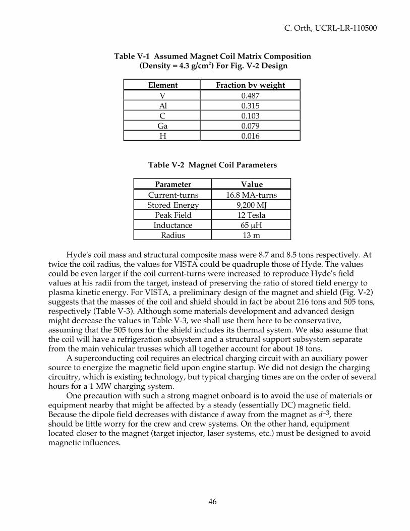
C. Orth, UCRL-LR-110500
46
Table V-1 Assumed Magnet Coil Matrix Composition (Density = 4.3 g/cm2) For Fig. V-2 Design
Element Fraction by weightV 0.487Al 0.315C 0.103Ga 0.079H 0.016
Table V-2 Magnet Coil Parameters
Parameter ValueCurrent-turns 16.8 MA-turnsStored Energy 9,200 MJ
Peak Field 12 TeslaInductance 65 µH
Radius 13 m
Hyde's coil mass and structural composite mass were 8.7 and 8.5 tons respectively. Attwice the coil radius, the values for VISTA could be quadruple those of Hyde. The valuescould be even larger if the coil current-turns were increased to reproduce Hyde's fieldvalues at his radii from the target, instead of preserving the ratio of stored field energy toplasma kinetic energy. For VISTA, a preliminary design of the magnet and shield (Fig. V-2)suggests that the masses of the coil and shield should in fact be about 216 tons and 505 tons,respectively (Table V-3). Although some materials development and advanced designmight decrease the values in Table V-3, we shall use them here to be conservative,assuming that the 505 tons for the shield includes its thermal system. We also assume thatthe coil will have a refrigeration subsystem and a structural support subsystem separatefrom the main vehicular trusses which all together account for about 18 tons.
A superconducting coil requires an electrical charging circuit with an auxiliary powersource to energize the magnetic field upon engine startup. We did not design the chargingcircuitry, which is existing technology, but typical charging times are on the order of severalhours for a 1 MW charging system.
One precaution with such a strong magnet onboard is to avoid the use of materials orequipment nearby that might be affected by a steady (essentially DC) magnetic field.Because the dipole field decreases with distance d away from the magnet as d–3, thereshould be little worry for the crew and crew systems. On the other hand, equipmentlocated closer to the magnet (target injector, laser systems, etc.) must be designed to avoidmagnetic influences.
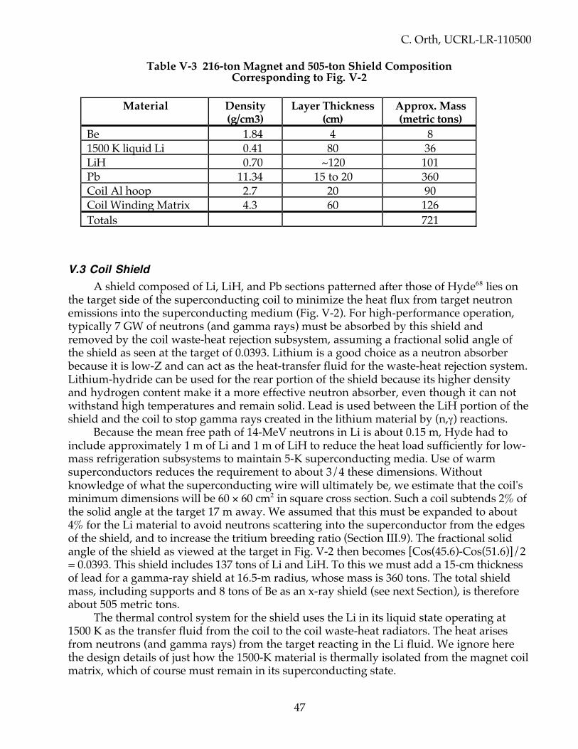
C. Orth, UCRL-LR-110500
47
Table V-3 216-ton Magnet and 505-ton Shield CompositionCorresponding to Fig. V-2
Material Density(g/cm3)
Layer Thickness(cm)
Approx. Mass(metric tons)
Be 1.84 4 81500 K liquid Li 0.41 80 36LiH 0.70 ~120 101Pb 11.34 15 to 20 360Coil Al hoop 2.7 20 90Coil Winding Matrix 4.3 60 126Totals 721
V.3 Coil ShieldA shield composed of Li, LiH, and Pb sections patterned after those of Hyde68 lies on
the target side of the superconducting coil to minimize the heat flux from target neutronemissions into the superconducting medium (Fig. V-2). For high-performance operation,typically 7 GW of neutrons (and gamma rays) must be absorbed by this shield andremoved by the coil waste-heat rejection subsystem, assuming a fractional solid angle ofthe shield as seen at the target of 0.0393. Lithium is a good choice as a neutron absorberbecause it is low-Z and can act as the heat-transfer fluid for the waste-heat rejection system.Lithium-hydride can be used for the rear portion of the shield because its higher densityand hydrogen content make it a more effective neutron absorber, even though it can notwithstand high temperatures and remain solid. Lead is used between the LiH portion of theshield and the coil to stop gamma rays created in the lithium material by (n,γ) reactions.
Because the mean free path of 14-MeV neutrons in Li is about 0.15 m, Hyde had toinclude approximately 1 m of Li and 1 m of LiH to reduce the heat load sufficiently for low-mass refrigeration subsystems to maintain 5-K superconducting media. Use of warmsuperconductors reduces the requirement to about 3/4 these dimensions. Withoutknowledge of what the superconducting wire will ultimately be, we estimate that the coil'sminimum dimensions will be 60 × 60 cm2 in square cross section. Such a coil subtends 2% ofthe solid angle at the target 17 m away. We assumed that this must be expanded to about4% for the Li material to avoid neutrons scattering into the superconductor from the edgesof the shield, and to increase the tritium breeding ratio (Section III.9). The fractional solidangle of the shield as viewed at the target in Fig. V-2 then becomes [Cos(45.6)-Cos(51.6)]/2= 0.0393. This shield includes 137 tons of Li and LiH. To this we must add a 15-cm thicknessof lead for a gamma-ray shield at 16.5-m radius, whose mass is 360 tons. The total shieldmass, including supports and 8 tons of Be as an x-ray shield (see next Section), is thereforeabout 505 metric tons.
The thermal control system for the shield uses the Li in its liquid state operating at1500 K as the transfer fluid from the coil to the coil waste-heat radiators. The heat arisesfrom neutrons (and gamma rays) from the target reacting in the Li fluid. We ignore herethe design details of just how the 1500-K material is thermally isolated from the magnet coilmatrix, which of course must remain in its superconducting state.
C. Orth, UCRL-LR-110500
48
One potential problem with the use of a conducting-metal shield is a possibledissipation of the distorted dipole magnetic field through radiation or induced-currentlosses. The latter would also constitute an added heat source for the shield radiators. Futurestudies must reveal whether or not these issues are important. If resonant dipoleoscillations ever become important, power losses can be reduced by injecting targets anti-phased with the dipole fluctuations.
The optimum size of the shield is a trade-off between excessive mass for a large shield,and insufficient tritium breeding and increased neutron-gamma irradiation of spacecraftcomponents and crew quarters for a small shield. Specifically, Hyde assumed 0.030 was asufficient solid angle for his geometry, but expanded it to 0.055 to enhance tritium breedingwhen Monte Carlo neutronics codes indicated that the tritium breeding ratio would be only54% for a solid-angle fraction of 0.030. We have not performed additional calculations forthe VISTA design, and leave to a future study just how these trade-offs would best beoptimized. Nevertheless, Sahin, et al.69 have calculated the neutron and gamma-ray heatingfor our shield design and found it to provide adequate protection for the superconductingmaterial for total fusion yields up to at least 17.5 GW. They recommend, however, that thecenter-line of the magnet within the shield be shifted from 50.00 to 50.15 degrees in Fig. V.2to reduce peak heating in a few isolated spots within the shield.
V.4 X-Ray Ablation Protection for First Wall & Final MirrorsTarget x-ray emissions do not heat the Li inside the coil shield due to their short
ranges, but they can cause serious erosion of the front metallic surface of the shield's Licontainment vessel and for the front faces of the final laser turning mirrors. Withoutconsiderable design effort to minimize this ablation, the mass loss per pulse can greatlyexceed the expellant employed per pulse, and mission performance is severely degraded.Such ablation therefore sets one of the most important design constraints on the size of thesuperconducting magnet, and hence on the entire spacecraft. This fact has not beenappreciated by any previous author in this field.
Using our own computer code for calculating x-ray deposition profiles, massesvaporized, and ablation momentum transfers, we calculate that the ablation of hundreds ofgrams of material per pulse off the inner coil shield from each 7500-MJ target fired in theHyde geometry can be avoided if 1) the shield inner surface is much further away thanabout 10 m from the target, and 2) the material employed for the front surface is one with alarge cohesive energy density, like carbon or beryllium. The last point can be understoodby noting that most materials have a similar cross section for x-ray absorption in terms ofg/cm2, so the material that is best is the one that can absorb the most energy per grambefore it melts or vaporizes. Moreover, our calculations suggest that it is impossible toreduce Hyde’s vaporization mass loss through protective schemes employing techniques tocoat the inner surface with expendable liquids (e.g. by wicking), or to puff gas in front ofthe surfaces to absorb the target emissions, because such techniques require about the samemass in the protecting agent as would be vaporized directly from the surface. Thesetechniques would therefore degrade jet efficiency because they do not effectively enhanceengine thrust, and eject low-velocity material at large solid angles. In addition, toaccommodate the optional emf-generating coil power-conversion system discussed in Sec.VI.3, the inner coil surface must be metallic (i.e. a good electrical conductor). The materialmust also be a good thermal conductor, to facilitate heat removal. We therefore use

C. Orth, UCRL-LR-110500
49
beryllium metal for VISTA. As added protection, we also plan to ripple or "spike" thesurface to increase the surface area and thereby decrease the heat loading per unit ofmaterial area.
We also suggest using some form of polished beryllium as the surface of the final laserturning mirrors, and to place them at a distance of 40 m. (The soft x rays from a 7500-MJtarget would still ablate at least 1 µm of Al at 25 m.) Distances greater than 40 m wouldreduce the thermal loading and should therefore be considered as well, for we know of nolimiting constraint on the placement of these mirrors—except for their mass, which wouldhave to increase for larger distances. Unfortunately, pure polished beryllium has areflectance of about 43% at 0.3 to 0.5 µm, so use of beryllium requires a developmentproject to obtain a surface having both high heat of vaporization and high reflectance.Stated differently, the final choice of driver wavelength may depend partly on thereflectivity of Be: a reflectivity too low will require a larger driver mass, and may introducecomplexity and mass in heat-rejection systems. Activation of the beryllium from targetneutron emissions should not create a radiological problem for the crew and should notsignificantly affect the structural integrity of the beryllium. On the other hand, in theunlikely case that grazing-incidence liquid-metal mirrors (GILMMs) can be developed forthis dynamical environment (complete with vibration), then reflectivity is not a problem.
V.5 Target Debris Plasma PhysicsAlthough one might at first view the expansion of the target debris plasma and its
interaction with the magnetic field as a simple adiabatic expansion of a hot plasma into avacuum and the deflection of this plasma by a huge magnetic field, closer inspection revealsthat rather complicated phenomena are involved. We have not taken the effort tounderstand much of the physics of these phenomena, even though some aspects are crucialto the engine's basic operation. A future study must therefore more fully address theseimportant issues.
The most important issue needing further experimental understanding is the timehistory of the conductivity of the debris plasma. This plasma must be sufficiently conductiveto expel the magnetic field and thus allow redirection of the plasma rearward, or the enginewill not operate. Initially, just after termination of the fusion burn, the plasma temperaturesvary from a few to tens of eV at its surface to hundreds of eV on its interior, and istherefore highly conductive. After 1 to 10 µs, when the plasma has expanded to a radius ofroughly 1 m, the thermal wave from its interior has already propagated outward andreached the surface, releasing a burst of soft x-rays, and the plasma has cooled down to theorder of 1 eV. This cooling process involves the conversion of the thermal energy intoradial kinetic energy, thus providing the high engine specific impulse (debris speeds near1/4 m/µs). The cooling process does not depend on external radiation (the hydrogenexpellant has no bound electrons when ionized). Even at 1 eV, the plasma conductivity isstill within about 3 orders of magnitude of metallic conductivities. Although there arequestions of plasma collisionality and plasma instabilities, the important question is howcold the plasma will become as it continues to expand, while continually being "reheated"through its own recombination. Sufficient cooling would of course lower the conductivityenough that some magnetic field could penetrate the outer portions of the debris duringthe deflection process, thus lowering the efficiency of the engine through energy lostduring field decoupling in the plume. That is, the outer fringes of the exhaust volume would

C. Orth, UCRL-LR-110500
50
suffer a kinetic-energy loss to supply the energy necessary to extract the field lines, and thismomentum loss would lower the effective jet efficiency. In addition, there is the possibilitythat charged particles that remain in the field-penetrated regions may tend to spiral aroundthe field lines and eventually impinge on spacecraft structures. Future studies may want toinvestigate the value of attempting to raise the plume’s surface conductivity using blastsfrom other lasers.
Decoupling of the plasma from the magnetic field in the plume depends on the beta ofthe plasma, which is the ratio of the particle pressure and the magnetic field pressure (i.e.the ratio of the kinetic energy density of the plasma and the energy density of the magneticfield):
Beta = nkT / (B2/2µ0) (17)
At the point of deflection, beta is near unity. In the plume, B is decreasing as r-3, whilethe particle energy is essentially constant, so beta increases rapidly. The plasma shouldtherefore decouple from the field with high efficiency, but detailed calculations proving thisare still lacking. Low betas would of course inhibit decoupling, thus causing drag, decreasedjet efficiency, and unwanted particle flow forward around the field lines and onto spacecraftstructures.
Zakharov, et al. 70 have confirmed the general features expected for the expansion ofa plasma in a dipole field through initial calculations and experiments. If future more-detailed studies indicate that plasma decoupling does cause excessive drag, one idea that hasbeen proposed is to add cold expellant to the exterior envelope of the exhaust as it exits thethrust chamber. This is generally not a good idea, however, because the resulting layeredplume then has a less conductive edge, which would promote further magnetic fieldpenetration with subsequent increased drag; moreover, a non-thermalized exhaustcomponent would reduce jet efficiency. Some investigators have also proposed using thishybrid-plume technique to control exhaust velocity in order to optimize propulsiveefficiency (the ratio of vehicle power to engine power) by making exhaust velocity matchvehicle velocity, but this would work only if the cold and hot exhaust components can fullythermalize—otherwise the jet efficiency is reduced. Techniques for plume velocitymodulation and plasma tuning at high temperatures (800 eV) have been extensively studiedby F. Chang-Diaz of NASA, and by T. Yang and W. Krueger of the MIT Plasma FusionCenter.71 A more efficient way to control plume velocity, therefore, is simply to vary themass of the expellant.
We here ignore the possibility of Rayleigh-Taylor and other instabilities in the plasmaflow because we believe that the time scale for the instabilities is much longer than thetransit time of the plasma through the engine. Total transit of the debris through the thrustchamber takes 100 to 150 µs. Detailed calculations of instabilities, however, are lacking. Inthe unlikely event that future studies indicate that instabilities are important, quenchmargin may have to be added to the design of the superconducting magnet.

C. Orth, UCRL-LR-110500
51
V.6 Plume Formation and Plasma Collection EfficiencyThe debris exiting the spacecraft from the thrust chamber and decoupling from the
magnetic field constitutes the exhaust. The plume geometry is determined by thedistribution of this exhaust in solid angle. This distribution is determined by the interactionof the debris with the magnetic field, and was calculated by Hyde.72
If future studies determine that it is necessary to increase jet efficiency by furtherrestricting the solid angle of exhaust exit, the plume can be shaped by employing othermagnets. Additional magnets, however, would involve additional dry mass, primarily insupport structure to resist the huge forces between magnet coils, and the additionalneutron coil shields that would be required to protect the superconducting media fromthermal influx. The additional coils and shields would also constitute mass not situatedbehind the coil shield for the thrust-chamber magnet, as viewed from other spacecraftstructure, so target neutrons could scatter in the mass of these other coils and shields andproduce a neutron background for the entire spacecraft. Thus, although plume-shapingcoils are an option, their use would complicate the spacecraft design.
The plasma collection efficiency of the thrust chamber with just one coil was calculatedby Hyde to be 64%.73 This value not only includes the loss of some plasma forward alongthe axis of the magnetic field, but also the effect of projecting all exiting debris momentaalong the single rearward thrust vector. This efficiency can be compared with a maximumvalue of 75%, which is obtainable only when the thrust chamber acts like a hypotheticallyperfectly reflecting paraboloid. The 64% can be increased very slightly by moving the targetsomewhat further away from the plane of the magnet coil, because Hyde reduced thisdistance (relative to the optimum distance) to enhance tritium production in the lithium coilshield. We will adopt the conservative value of 64% for VISTA.
V.7 Jet EfficiencyThe physics of the plasma dynamics in the magnetic thrust nozzle of an IFR is not fully
understood, but certain qualitative comments can be made. The jet efficiency of an IFR is
ηjet = Pjet / Pinput (18)
where we take the input power to be the sum of the driver power and the power releasedby the fusion target, Pinput = Pd + Ptarget = Pd (G+1), and the jet power is defined by
Pjet = F2 / (2 dm/dt) (19)
Here dm/dt is the total rate of mass flow from the propulsion system and F is themagnitude of the directed propulsive force or thrust exerted by the propulsion system. In atraditional rocket motor, dm/dt is the propellant mass flow rate, but in general, dm/dtmust also include the flow of any non-propellant masses required for operation of thepropulsion system (such as non-recovered target radiation shields). Note that the definitionof specific impulse, using these variables, is
Isp = F / (dm/dt) (20)

C. Orth, UCRL-LR-110500
52
which has the units of velocity in MKS units (but pound-force-seconds per pound-mass inEnglish units). This is the reason why the term effective exhaust velocity is sometimes usedinstead of specific impulse, but specific impulse is equal to exhaust velocity only for a perfectmono-velocity beam of expellant fluid.
Several loss mechanisms have been identified that reduce jet power, and hence jetefficiency. The best understood of these mechanisms is the hydrodynamic loss caused bythe imperfect collimation of the expanding plasma debris. As we mentioned above, notonly is there a distribution of exiting angles scattered about the direction of thrust, but thereis a small loss of plasma forward along the axis of the superconducting magnet. Hyde74
addressed these effects based on the assumption of perfect conductivity for the plasma (nomagnetic field penetration of the plasma), and determined a loss in jet power of near 59%(that is, 1 - 0.642). For comparison, a specularly reflecting hemisphere deflecting the plasmadebris in a manner similar to that employed in the Daedalus study75 would lose 75% of thejet power.
Diffusion of the magnetic field into the plasma prior to plasma-field decoupling alsocauses a loss in jet efficiency, because the plasma is not perfectly conducting. A qualitativemeasure of this loss can be obtained by the ratio of the transit time of the plasma throughthe thrust chamber and the characteristic time for magnetic field diffusion into the plasma.The latter is given by
t = (µ0 L2) / h (21)
where µ0 is the permeability of the vacuum (4π × 10-7 in MKS units), L is the scale length ofthe spatial variation of the magnetic field (a few meters), h is the (Spitzer) resistivity of theplasma,
h = 0.05 TeV-3/2 ohm-cm (22)
where T is the electron temperature of the plasma. If the plasma temperature were toremain at its cooled state of 1 eV even though it expanded beyond a radius of about 1 m,the resulting time t of about 250 µs would be comparable to the 100-150 µs transit timethrough the thrust chamber. Thus, the IFR operates in a realm where the details determinewhether the plasma conductivity is high enough to keep the magnetic field out. Asindicated above, a future study must address these details. Here, we will arbitrarily assumethat the diffusion loss is about 10%. Due to the uncertainty in this value, we will not discussin detail what happens to the plasma penetrated by the magnetic field. Some of this plasmawill eventually separate from the magnetic field by ambipolar diffusion and exit thespacecraft in arbitrary directions. Some may remain trapped in the field and interact withspacecraft structure.
Lost thermal energy stored in the ionization of the expellant as the exhaust departsfrom the vicinity of the spacecraft is one frozen-flow loss that is potentially significant forlow exhaust velocities. For our system, however, operating with a typical exhaust velocityof 270,000 m/s, the kinetic energy of each H expellant ion is about 400 eV, while theionization energy is 13.5 eV. Low recombination rates would thus imply a loss of 3% atmost. However, we anticipate high recombination rates by the time the exhaust is exitingthe thrust chamber (even though this may cause plasma drag as explained in Section V.5),so we will ignore ionizational losses.
C. Orth, UCRL-LR-110500
53
Thermal radiation from the plasma can cause losses in jet power, but not for hydrogenuntil recombination occurs, because there are no bound electrons in the plasma state. This isone advantage for using a hydrogen expellant. Jet power can also be lost due to a non-mono-energetic exhaust velocity distribution. Such a velocity distribution can result directlyfrom the engine operation, or indirectly through multiple ion species of widely differentatomic masses (and therefore different velocities). In the IFR case with hydrogen expellantand no hybrid plume components, only the dispersion in velocity distribution is important.We did not determine the nature of this dispersion for an IFR, however, because thedispersion of velocities of the ions exiting the target location is modified by interaction withthe magnetic field to form a more mono-velocity distribution. The target dispersion isroughly a factor of 2, so the final dispersion should typically be much less than a factor of 2in velocity. A linear velocity distribution over a relative velocity range of 1.0 to 1.5 wouldlead to a loss of only 1.3% in jet efficiency.
Another consideration is whether the spacecraft structure absorbs some of the impulsevibrational energy from the repetitive target firings, thereby causing a decrease in theeffective jet efficiency. Preliminary calculations, however, suggest that this is a negligibleloss (Q << 1).
The above losses in jet power total at least 68%, but a lower value is appropriate for amore optimum placement of the target in relation to the magnet coil plane, or if additional(but perhaps impractical) plume-shaping coils are employed. For VISTA, we originallyassumed a total loss of 66% and thus a jet efficiency of (1.00-0.66) or 34% so that themomentum efficiency of the engine (which is the square root of the jet efficiency) was 0.583(i.e., ~0.6). However, with the later, more-accurate system descriptions (see Sec. XI.2), thejet efficiency dropped to 32%.
V.8 Inductor EMF Power Conversion OptionOne option for power conversion is the use of a conducting path on the inside of the
coil shield so that, when the debris interacts with the magnetic field and compresses thefield lines, these lines cross through the conducting path and generate an emf. This emf canbe utilized as discussed in Sec. VI.3 to generate power for the driver. The advantages ofsuch a system are a great reduction in mass and improved efficiency of the power-conversion system in comparison to those for a Rankine system.
The most suitable choice for the conducting path is the interior surface of the coil shielditself, because the emplacement of an additional coil here would complicate the shieldingand create huge structural forces between the main magnet coil and any physically separatepickup coil. The choice of beryllium as the interior shield liner for ablation protection iscommensurate with the conducting requirements for the conducting path. Thus, theablation protection system can serve both functions with no additional mass required.
V.9 Blanket OptionsAnother concept for power conversion is the use of spherical sectors purposely placed
in the path of the target neutrons at about the same radius (or perhaps slightly larger radii)from the target than the coil shield. These sectors would have an interior beryllium ablationliner, just like the coil shield, and would contain liquid lithium for heat transfer (see Sec.VI.1). Such systems would act much like a coil shield that subtends much more than 4% of

C. Orth, UCRL-LR-110500
54
the total solid angle (see Fig. V-2). They are referred to as blankets (because of the analogywith similar systems in terrestrial IFE facilities). The purpose of these blankets is to absorbmore neutron energy, and convert the energy to power suitable to operate the driver.
The best location for the blankets depends on their subtended angle. Small blanketscould in effect be extensions of the coil shield, but larger systems could be located extendingfrom the coil shield towards the coil axis. One constraint is to avoid neutron scatter towardsother spacecraft systems, so blankets must be nearly as thick as the coil shield. As such,blankets are very massive, at least 30 tons for every 1% of solid angle (and 20 to 50% wouldbe required!). This is just one feature that makes blankets vastly inferior to the inductor coiloption.
V.10 Shock IsolationSignificant impulse is imparted to the coil structure only during a few meters of debris
transit around the place of peak field compression. Engine impulse therefore lasts only onthe order of 10 µs. A NASTRAN computer analysis of the conical spacecraft structureindicated that special shock isolation of spacecraft components from the magnetic drive coilimpulsive shock loading is not required. The mass of the drive coil itself and the complianceof the surrounding support structure form a sufficient mass-spring momentum absorber tosharply attenuate the drive pulse peak loads. Several meters out along the conical shellaway from the drive coil, only an averaged acceleration is seen by the structure because theeffective spring-constant time of the structure is much longer than the inverse targetrepetition frequency of roughly 1/30 Hz = 30 ms.

C. Orth, UCRL-LR-110500
55
VI. POWER SYSTEMS
The power systems must be capable of supplying pulses to operate the laser driverplus approximately 1 MW of auxiliary dc power. The power for the driver dependsinversely on the efficiency of the driver, and is a maximum of 2.5 GW at 30 Hz for a6%-efficient driver, as originally envisioned for VISTA, but only 1.25 GW at 30 Hz forVISTA’s 12%-efficient DPSSL driver. The power systems consist of two subsystems: apower-conversion system to extract power from the fusion process, and a power-conditioning system to form the proper electrical pulse shapes to operate the driver andother electrical equipment.
VI.1 Overall ConceptsPower to operate spacecraft systems must come from the fusion reactions because the
gigawatts of average power required cannot be obtained with solar arrays of practical size(nor do we want VISTA to be dependent on solar illumination). The total power availablefrom the fusion reactions is up to 100 times the required electrical power. The emphasis inthe design of the power systems is thus how to extract a small part of the fusion powerusing a system of minimal mass.
The mass of the power system is in turn very dependent on the technique used toobtain the power, and the available techniques depend on the timing pulse widthsconsidered. For example, the fusion reactions offer a 10-µs time scale of the fusion impulsein the thrust chamber as well as an essentially dc pulse available by absorbing the neutronand/or x-ray emissions as heat energy in either the coil shield or an external blanketabsorber. To use the thrust-chamber pulse, the power systems must convert the 10-µs timescale to the millisecond pulse widths required by the laser diodes used to pump theamplifier gain media for a DPSSL driver. This can be done directly, or by going through adc stage. If the system uses neutron depositions in an external blanket, the technique wouldforce the use of a dc heat stage. Any system requiring conversion through a dc stage willgenerally be more massive than a system which merely extends the 10-µs scale by a factorof 100 and stays in the pulsed domain.
The pulse width required by the driver is also important. If a KrF driver wereconsidered instead of a DPSSL, for example, the short relaxation times of the KrF lasingstate would require input pulses with a width of only ~400 ns. Compressing the time scaleof the 10-µs thrust-chamber pulse to 400 ns might require more complicated circuitry thanlengthening it to 1 ms for a DPSSL. Although future developments in excimer lasers mightincrease the required pulse lengths for practical excimer lasers, we will here assume that 1-ms pulses will be required, as for a DPSSL. (The time scale for a DPSSL might even belonger than 1 ms, depending on the development of crystal gain media with longer storagelifetimes.)
The primary objective for an IFR power-conversion system is thus to extend the fewto 10-µs pulse period of the thrust impulse to get the 1-ms pulse widths needed for the laserpump diodes for a DPSSL. Two overall systems concepts were considered for such power-conversion in VISTA: 1) a Rankine system utilizing the dc waste heat deposited in thesuperconducting magnet coil's lithium shield by target neutrons and gamma rays, and 2) an

C. Orth, UCRL-LR-110500
56
inductor-coil option that generates an emf through magnetic induction upon compressionof the coil's magnetic field by the expanding target debris plasma.
The Rankine system starts with a dc heat source created as the lithium shield integratesincident neutron energy. It uses current technology (and is therefore a good backup option)and was designed in detail. Unfortunately, the Rankine system is only 20% efficient ifoptimized for minimal mass. As a result of both the dc nature of the conversion (whichnecessitates a massive electrical storage system) and the system inefficiency (whichincreases the mass in waste-heat radiators), the mass of the Rankine system is over 1,000tons. Use of the Rankine system would in fact increase the dry mass of the spacecraft bymore than 50% relative to the dry mass that results for use of an induction system. This isunfortunate, because the thrust chamber utilizes only the debris-plasma target emissionsand treats the absorbed neutron/gamma-ray energy that heats the lithium in the coil shieldas something to expel as waste heat, whereas the Rankine system would use a portion ofthese other target emissions that are simply radiated away as waste heat.
The inductor system, originally proposed by Hyde,76 uses the inherent time scale ofthe target debris emissions, and therefore involves minimal mass for the conversionsystem. The total mass of the power system is therefore determined more by the associatedpower-conditioning system. In particular, if the inductor power is rectified so thatcapacitative storage is required, the power-conditioning mass will be at least 100 tons.Although this mass is much less than that for a Rankine system, the objective is obviouslyto design an inductor conditioning system that uses efficient pulse expansion (and hence nodc stage) to achieve minimal added system mass. We have not developed such a design, sowe leave that as a task for a future study. To be conservative, the baseline option for VISTAis the inductor-coil power-conversion system with a capacitative-based power-conditioningsubsystem. The total mass of this system is about 115 tons.
It is very important to note that the induction system extracts power that wouldotherwise be used for thrust, whereas the Rankine system does not. The induction systemis therefore practical only for large target gains, because only for such gains is the debris-plasma energy very large in comparison with the energy [Edr/(driver efficiency x inductor-power-conversion efficiency)] required for the driver input.
Utilization of the fusion reactions for power conversion obviously necessitates the useof another electrical power generation system to start the fusion engine. We have notdesigned this engine startup system in detail, but its design is not critical, and is addressed inSec. VI.7.

C. Orth, UCRL-LR-110500
57
VI.2 Overall Power FlowFigure VI-1 shows the overall power flow for VISTA for a piloted Mars mission with
target gain G = 1500 (advanced technology) using the inductor power system andmaximum reprate (30 Hz). Note that 207 GW of the 225 GW of fusion power are simplyradiated to space! The neutron-multiplication factor of 1.15 adds 0.74 GW of waste heat inthe coil shield A little more than 1% must be recycled to operate the driver through theinduction power system. The jet efficiency is 18.86/(52.81+2.50) = 34% here, although 32% ismore precise for the updated system descriptions of Sec. XI.2. Figure VI-2 shows the powerflow using a Rankine system, which optimizes at 12.5 Hz and a jet efficiency of 35.7%. Theenergy-multiplication factor of 1.15 is described in Sec. VI.5.
Figure VI-1: Overall Power Flow (in GW) for the Advanced-TechnologyMission to Mars Using the Inductor Power System and Maximum Reprate
Obviously, one effective way to increase the performance of VISTA is to improve theefficiencies of the various subsystems.
12%-effic.Driver
G = 1500Target
7% LaserCoupling Loss
Neutrons
X rays
Plasma Debris3.93% HitStructure
Lost to Space
Available ThrustChamber Power
AvailableExhaust Power
EstimatedPlasma Drag
Jet Power
Waste HeatRadiators
Inductor Power System1.25
0.15
1.10 225.00
2.50
1.25
15.75125.39
4.93 x 1.15120.46
28.55
1.12
27.4355.31
52.816.79
14.42
47.53
5.28
18.86
28.67
206.73 total

C. Orth, UCRL-LR-110500
58
VI.3 Inductor Power SystemThe inductor system extracts power from the expanding target debris plasma as the
magnetic-field lines are shoved ahead of the plasma and compressed and thendecompressed in the process of deflecting the plasma rearward for thrust. The aspect of thisprocess that is important here is that the magnetic field lines are moved in space towardand then away from the coil windings. Therefore, if another (inductor) coil loop is placedinside the superconducting coil so that the moving magnetic-field lines cross the inductorcoil, an emf is generated according to the change in magnetic flux passing through theinductor loop. The emf would have one sign during compression of the lines, and theopposite sign during decompression of the lines. The emf thus has the same time scale asthe debris-magnet interaction (a few to 10 µs). The extracted energy due to the induced emfis small (≤5%) compared with the total energy being converted from plasma kinetic energyto magnetic potential energy and back to kinetic energy, so engine thrust is not significantlyaffected. This is the essence of the inductor power-conversion system. Several options arethen available for the power-conditioning subsystem.
Figure VI-2: Overall Power Flow (in GW) for the Advanced-TechnologyMission to Mars Using the Rankine-Cycle Power System
12%-effic.Driver
G = 1500Target
7% LaserCoupling Loss
Neutrons
X rays
Plasma Debris
3.93% HitStructure
Lost to Space
Available ThrustChamber Power
AvailableExhaust Power
EstimatedPlasma Drag
Jet Power
Waste HeatRadiators
Rankine Power System0.52
.063
0.46 93.92
2.61
2.09
6.5852.39
2.06 x 1.1547.72
12.11
0.48
11.6322.85
22.85
0.245.07
20.57
2.28
8.16
12.41
83.41 total

C. Orth, UCRL-LR-110500
59
VI.3.1 Inductor Power Conversion SubsystemLarge forces may develop between the superconducting coil and the inductor coil
because the generated emf produces fields which oppose the change in magnetic fluxthrough the inductor loop. It is therefore practical to use just the interior surface of thesuperconducting magnet coil shield (i.e., the beryllium interior ablation liner) to serve as theinductor loop, instead of incorporating a physically separate inductor loop. It may even bepossible to use the lithium liquid in the coil shield as the loop conductor. We leave to afuture study just how this system should be optimized.
If the interior surface of the coil shield serves as the inductor loop, it has threefunctions: 1) to contain the lithium neutron absorber, 2) to act as an inductor coil, and 3) toprevent material vaporization from incident x-rays. This material may be electricallydivided into the equivalent of multiple windings to form a modular and/or redundantsubsystem, if needed. The total mass of this part of the subsystem is insignificant, so variousoptions should be considered.
For a typical pulse, the rise and fall time of the inductor signal is roughly severalmicroseconds. The bulk of the power conversion system lies in expanding this signal to the1-ms pulse needed for the driver laser diodes, and in delaying the converted pulse for oneengine cycle. We did not design this important part of the conversion subsystem, and leavesuch details to a future study.
As a backup conversion system, we examined the feasibility of a modular system toconvert the inductor signals to a dc 600-kV level for use by a KrF-type driver. For 5 MJ ontarget and a 6% efficient driver, 83 MJ are required per pulse. As an example, note that thisis easily supplied electrically by 260 modules, each of which supplies 320 kJ through anequivalent circuit that is a series LC of 0.5 mh × 4 mf with an opening switch. The switchopens at peak field compression, and must be able to carry 750 kA and resist a back voltageduring the field decompression phase. Even though the availability of such switches in theVISTA time frame is highly likely, this subsystem is quite massive because it introducescapacitative storage and is thus undesirable.
VI.3.2 Inductor Power Conditioning SubsystemBecause we did not design the inductor power system in detail, we cannot give precise
masses for the subsystems. We feel, however, that the baseline inductor system will have amass that is insignificant compared with other spacecraft systems, unless the backupcapacitative subsystem is incorporated. In the latter case, the same type of systememploying resonant capacitative discharge or the discharge of charged transmission linescan be used here as for the Rankine power-conditioning subsystem.
VI.4 Rankine Power SystemThe backup power system consists of a 20%-efficient Rankine power cycle utilizing the
neutron deposition in the superconducting magnet coil shield and a companion lithiumblanket as a heat source. The Rankine system feeds a power conditioning systememploying a high-frequency turbo-alternator with capacitative storage. The relatively lowefficiency for the Rankine system is based on minimum-mass rather than maximum-efficiency considerations. We designed the entire system based on a KrF-type driver, as
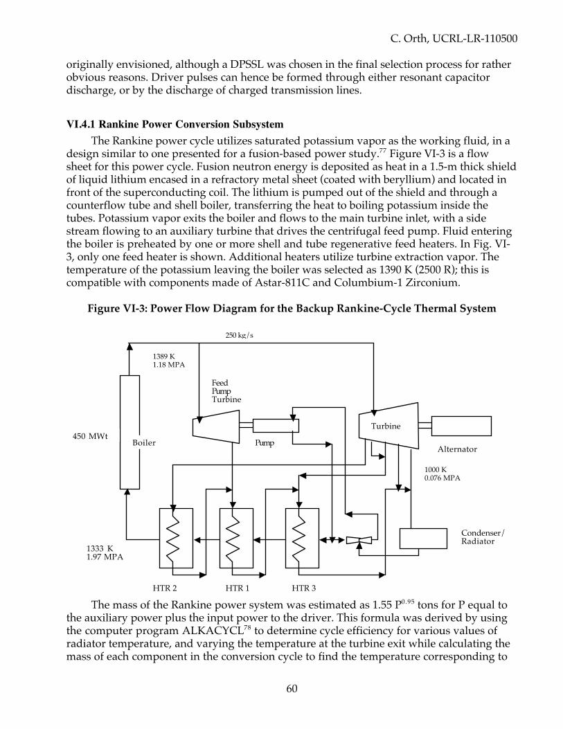
C. Orth, UCRL-LR-110500
60
originally envisioned, although a DPSSL was chosen in the final selection process for ratherobvious reasons. Driver pulses can hence be formed through either resonant capacitordischarge, or by the discharge of charged transmission lines.
VI.4.1 Rankine Power Conversion SubsystemThe Rankine power cycle utilizes saturated potassium vapor as the working fluid, in a
design similar to one presented for a fusion-based power study.77 Figure VI-3 is a flowsheet for this power cycle. Fusion neutron energy is deposited as heat in a 1.5-m thick shieldof liquid lithium encased in a refractory metal sheet (coated with beryllium) and located infront of the superconducting coil. The lithium is pumped out of the shield and through acounterflow tube and shell boiler, transferring the heat to boiling potassium inside thetubes. Potassium vapor exits the boiler and flows to the main turbine inlet, with a sidestream flowing to an auxiliary turbine that drives the centrifugal feed pump. Fluid enteringthe boiler is preheated by one or more shell and tube regenerative feed heaters. In Fig. VI-3, only one feed heater is shown. Additional heaters utilize turbine extraction vapor. Thetemperature of the potassium leaving the boiler was selected as 1390 K (2500 R); this iscompatible with components made of Astar-811C and Columbium-1 Zirconium.
Figure VI-3: Power Flow Diagram for the Backup Rankine-Cycle Thermal System
The mass of the Rankine power system was estimated as 1.55 P0.95 tons for P equal tothe auxiliary power plus the input power to the driver. This formula was derived by usingthe computer program ALKACYCL78 to determine cycle efficiency for various values ofradiator temperature, and varying the temperature at the turbine exit while calculating themass of each component in the conversion cycle to find the temperature corresponding to
450 MWtBoiler
1389 K1.18 MPA
250 kg/s
FeedPumpTurbine
Pump
1333 K1.97 MPA
HTR 2 HTR 1 HTR 3
Turbine
Alternator
1000 K0.076 MPA
Condenser/Radiator

C. Orth, UCRL-LR-110500
61
the minimum total mass. The program also outputted the energy balance, line sizes, andmasses for the piping and feed heaters. We determined the masses of the majorcomponents separately, using this program. Individual components, and the scaling lawsused for each, are discussed in the following paragraphs. For the case shown in Fig. VI-2,the total mass was 569 tons in equipment plus 140 tons in radiators (709 metric tons total);this is much more than the 115 metric tons required for the inductor power system.
We included the possibility of adding a lithium blanket enclosed by Nb-1-Zr walls(coated on the interior side with beryllium) for the case in which the 3.93% solid angleoccupied by the coil shield proved insufficient in absorbing enough power from targetneutrons and gamma rays to operate the driver. The thickness of all walls was to beestimated for a 99% survivability in the interplanetary micrometeoroid environment for amission of at least 80 days. We found, however, that only 3.5% of the solid angle wasnecessary for power absorption with the Rankine system, so no additional blanket wasrequired. Nevertheless, we continued to design the Rankine system as if a blanket were tobe incorporated.
We sized the lithium piping of the primary heat transport loop to provide steady-stateheat removal from the lithium blanket. For this purpose, we assumed a 200-C temperaturedrop through the boiler and a flow velocity of 6.1 m/s. Like the lithium shield, the pipingwall thickness was selected for protection from micrometeoroid damage.
An EM pump circulates the lithium through the boiler. The pump mass is a function ofboth the volumetric flow rate and the pressure drop through the lithium piping. The flowrate increases directly with system thermal power. For a fixed length of piping, the pressuredrop decreases slightly as the flow rate increases, due to increased pipe size. As a result,pump mass scales very closely with system thermal power.
The turbine is an axial flow type with nine stages and two interstage moistureseparators. The stage efficiency is equal to the dry stage efficiency (0.85) degraded by stagemoisture. Turbine size depends largely on the total volumetric flow through the turbine.Based on a previous study,79 a specific mass of 70 kg/(m3/s) of turbine outlet flow wascalculated for a turbine of 100 kWe output. The scaling of turbine size with power is difficultto determine, because potassium vapor turbines for megawatt size have not been built. Asthe turbine size increases, its efficiency increases, suggesting a scaling exponent less thanunity. However, the wall thickness must also increase as power goes up due to the largecomponent size. We determined a scaling exponent of 0.9 by comparing the turbine massesfor 350 kWe and 10 MWe potassium Rankine power cycle designs having approximately thesame temperature conditions.80
We assumed that the generator mass scales like a transformer mass, namely to the0.75 power.81 At 5 MWe output, we assumed that the generator has a specific mass of 0.1kg/kWe. The number of boiler tubes, and thus the total tube mass, is directly proportionalto the thermal power absorbed by the shield. The boiler shell diameter and shell thicknessboth increase with the square root of the thermal power; thus, the total scaling factor is adirect function of thermal power. We obtained a boiler specific mass of 0.025 kg/kWt basedon an overall heat transfer coefficient of 8500 W/m2K,82 a tube-to-shell temperaturedifference of 111 C, and a factor of 1.5 to account for shell mass. We obtained secondaryloop sizes and feed-heater masses from the computer program ALKACYCL. Thesecondary piping also has micrometeoroid-protective shielding. The heat pipe radiatorconsidered for these calculations, however, is not shielded; we sized the wall thickness to
C. Orth, UCRL-LR-110500
62
accommodate internal pressure only. We assumed that excess heat pipes are installed at thebeginning so that 10% can be lost to micrometeoroid damage during operation.
We assumed here that the radiator was an array of heat pipes of Nb-1-Zr constructionusing sodium as a working fluid. Potassium vapor leaving the turbine condenses as itcomes in contact with the evaporating sections of several heat pipes embedded in theturbine outlet piping. The piping tapers as the potassium condenses and subcools beforeentering the feed pump. We assumed that the radiating temperature is 100 K less than theturbine outlet temperature. The radiator design has an assumed specific mass of 0.13kg/kW of reject heat at 900 K, and scales with radiator temperature to the fourth power.More advanced radiator designs are of course possible.
We estimate that a minimum total mass of 450,000 kg occurs at a radiator temperatureof 900 K. Of this mass, 14,000 kg is due to the alternator. Thus the total Rankine-systemmass is 436,000 kg. At 900 K, the lithium blanket is the heaviest component. It increaseswith temperature because the cycle efficiency decreases, and a greater thermal power isnecessary to output the required electric power.
The turbine mass decreases with radiator temperature. As the radiator temperatureincreases, the mass flow rate increases to provide the same power output at a lowerefficiency. However, a higher radiator temperature corresponds to a higher saturated liquidpressure, which has the effect of reducing volumetric flow rate even though the mass flowrate is increasing. The turbine curve turns upward at higher temperatures when the massflow increase dominates the volumetric flow decrease. The generator mass remainsconstant as the radiator temperature increases, since electric power output is held constant.
A minimum radiator mass occurs because specific mass decreases with radiatortemperature while the amount of heat rejection increases due to the decreasing cycleefficiency. A minimum mass of 130,000 kg occurs at 1000 K although the curve is very flatbetween 950 K and 1025 K.
The boiler mass increases with radiator temperature as the efficiency decreases.Primary piping and EM pump mass both increase in order to accommodate the larger flowrate due to a higher thermal power. Secondary piping mass decreases because although theflow rates are increasing, the turbine outlet pressure also increases with temperature,keeping the piping sizes small.
The high-frequency turbo-alternator delivers 3-phase ac current at 1500 Hz andtypically 15 kV. The 3-phase output allows acceptable low voltage ripple on the dc bus,requires a modest rectifier parts count, gives adequate rectifier utilization, and simplifiesalternator and transformer design.
VI.4.2 Rankine Power-Conditioning SubsystemThe purpose of the power conditioner is to accept alternator output voltage and
convert this ac source of power into high-energy short-duration pulses used to drive thefusion driver. In order to minimize system mass and optimize efficiency, the powerconditioner uses a single multi-megawatt 3-phase transformer to perform primary acvoltage step up and electrical isolation. The transformer output is processed with a 3-phasesolid-state bridge silicon-controlled rectifier/voltage regulator, and an inductor to providesignal filtering and current limiting in the case of driver fault. The processor is assumed toincorporate high-efficiency, low-mass, moderate-to-fast fault interruption. The output ofthe processor feeds a capacitor-storage network. We selected capacitor storage to obtain a
C. Orth, UCRL-LR-110500
63
system with high specific energy, low specific mass, and rapid rise-time discharge. Thedriver is powered from the capacitor bank through a pulse-forming network and a loadswitch. The capacitors can be resonantly discharged into the load, or even better, throughthe discharge of charged transmission lines. Distribution to other systems would bethrough conditioners that would provide the correct potential and modulation for eachsubsystem.
For the case of a 280 MWe unit, we estimated the combined specific mass of the PowerConditioning/Processing Unit (PPU) to be 0.37 kg/kWe exclusive of radiators. The designof the buffer capacitors is based on both the solid dielectric capacitor technology developedby Maxwell Labs (funded by the Defense Nuclear Agency), and state-of-the-artpolypropylene film technology developed by Sandia National Laboratory (G. W. Mauldin,principal investigator). The total specific energy will be between 400 J/kg and 4000 J/kg.The specific volume is between 0.6 and 0.8 J/cm3, with 2 MV/cm. The plate material isaluminum.
The mass of the capacitor network can vary from 5 to 55 tons at 20 MJ, using theabove parameters. The total mass of the power conditioning subsystem for typical driverinput requirements (6%-efficient driver with 5-MJ illumination on the fusion target, andhence 83 MJ of driver input—not 20 MJ) is correspondingly between 100 and 400 tonsexclusive of radiators. Total system efficiency is 97.5%. New device developments assumedinclude improved semi-conductor switches (high-voltage and high-current, and very fastdeep-impurity double-doped silicon devices), capacitors (new materials and new coolingtechniques with objective of high energy density and low loss for pulsed operation), andhigh-frequency magnetic materials for transformer size reduction and efficiencyimprovement. Obviously, without further technological developments, the Rankine power-conditioning subsystem will be very massive.
VI.5 Energy Multiplication FactorAs the neutrons and gamma rays leave the target/expellant region and interact in the
structure of the coil shield and/or thermal blanket, exoergic (energy-producing) nuclearreactions can occur (e.g., in Be and 7Li). These reactions can typically increase the depositedenergy by a factor of 1.14 through immediate neutron and gamma-ray multiplication.Short-lived activation products tend to increase the energy multiplication factor to 1.17 or1.18 as these products decay (e.g., by beta decay). If materials such as manganese are addedto take advantage of additional exoergic (n,n’) reactions, the energy multiplication factorcan be increased even further. For VISTA, we assume a conservative value of 1.15. Thepower flow in VISTA is therefore enhanced by this factor for all energy arising from fneut,the fractional energy in “neutron” emissions (Sec. III.6). We emphasize that such energymultiplication is not desirable for VISTA, as it is for terrestrial power production, so ourapproach here with a multiplication factor of 1.15 is very conservative! We assume thatfuture studies will demonstrate how this multiplication factor can be substantially reduced.
VI.6 Auxiliary Power SystemApproximately 1 MW of dc power must be generated to operate auxiliary equipment,
such as the following: crew systems and payload housekeeping; Rankine-cycle blanket EMpumps; EM pumps for coil shield and driver coolants; refrigeration systems (compressors

C. Orth, UCRL-LR-110500
64
and pumps) for the superconductor, propellant tanks, and final laser turning mirrors; targetfabrication, acceleration, and injection facilities and coolant systems; load controllers; systemand reaction (attitude) controllers; and communications. This power can easily be suppliedas a negligible addition to the main power-conditioning subsystems. About 10% of thepower can be supplied by the engine startup power system. In either case, essentially noadditional mass penalty is incurred by the auxiliary system, because the subsystemsrequired are already in existence.
VI.7 Engine Startup Power SystemA separate power-generation system is needed to supply roughly 83 MJ to fire the first
driver pulse, melt the lithium in the coil shield, and supply power for crew needs duringcoasts periods or when orbiting a planet. If a 100 kW SP-100-type system is used, it couldsupply the start-up power in less than 10 minutes. Such a small fission reactor would havean estimated mass (including coolant and all of the associated equipment) of 5 tons. Thissystem could be kept at minimum power output during engine operation, and would thensupply a negligible part of the auxiliary power requirements for the spacecraft.
VI.8 Uncertainties in Power Generation and Their EffectsIt is important to understand that, when flight hardware is developed and a flight of
VISTA occurs, there will be uncertainties in power generation, systems masses, and systemperformance that can each affect the roundtrip time for any mission. These uncertainties aremany, including particularly the attained performance of various engine and power-systemcomponents relative to what VISTA design specifies for performance and system mass(e.g., uncertainties arising from an incomplete understanding of each system, and the masscontingencies considered section XI.3). There are also the variations from specifiedperformance under actual flight conditions due to unforeseen or uncontrollableenvironmental factors or whatever. Of special concern is the effect of these uncertainties onjet power, radiator performance, and other system factors that can affect performancedirectly or indirectly through increases in vehicle wet mass. Rather than describe the detailsfor each system mentioned in this report, we have instead made Monte Carlo runs in whichEVERY system parameter for VISTA was randomly varied with its own Gaussiandistribution having a standard deviation of 10%. We report the effects on trip time inSections XI.4 for Mars missions and XII.2 for missions to Jupiter and Pluto. The netuncertainty in trip time had a standard deviation that varied from only 7 to 13% dependingon the mission.

C. Orth, UCRL-LR-110500
65
VII. THERMAL CONTROL SYSTEMS
Thermal control systems are required to remove waste heat generated frominefficiencies in the driver and power systems, and from the deposition of target emissionsin the coil shield (and blanket, if used). Thermal control (refrigeration) is required tomaintain the temperature of the superconductor for the magnet, and the temperature ofthe propellant tanks.
VII.1 Concepts and Effects of Technology DevelopmentThe most massive thermal-control systems are the radiators that remove waste heat.
These systems must radiate about 6,000 MW at peak engine output. With currenttechnology suggesting specific masses near 0.2 kg/kW (i.e., 0.2 tons/MW) for heat-piperadiators operating at 1,000 K with 14 kg/m2, the mass of these systems is 6,000 x 0.2 =1,200 tons. Such a mass would severely restrict vehicle performance.
The radiator mass can be reduced by operating at higher temperatures, and usingmore advanced radiator designs. Because the radiators for the coil shield eliminate most ofthe radiated power, we have chosen their operating temperature to be 1500 K. Thistemperature is compatible with a lithium transfer fluid, which is already present in the coilshield. We also anticipate (and assume) that the specific radiator mass at 1,000 K can belowered to about 0.07 kg/kW at 1,000 K. The detailed design of the radiators is left for afuture study, but is essentially current technology. The results of these two improvementsreduce the total mass of radiators down to a couple hundred tons.
It is important to understand that vehicle performance is highly dependent on radiatortechnology (i.e. radiator specific mass) even though the fraction of total spacecraft mass inradiators is typically near 10% for VISTA. The fractional vehicle mass in radiators,wradiators, can be approximated for a continuously running engine by the ratio of theradiator mass and the wet mass, the latter being roughly the propellant mass divided by 0.7(because the propellant mass is roughly 0.7 of the wet mass). Thus,
wradiators = k Edr [1.15 GΩfneut + (1-εdr)/εdr] / {[t mtarget]/0.7} (23)
where k is the specific radiator mass, Edr is the driver energy in MJ, G is target gain, Ω is thefractional solid angle subtended by the coil shield, fneut is the fractional fusion energy intoneutrons, εdr is the driver efficiency, t is the roundtrip travel time in seconds, mtarget is thetotal target mass in tons, and we have not explicitly shown the dependence on temperatureT. Within any one material range, the radiator mass varies as T-4, but over a wider rangethan just one material and when increased pipe wall thicknesses are considered for highertemperatures, it varies approximately as T-2. We have assumed the latter dependence, sothat we can cover wide ranges in T. In any case, for VISTA parameters and a 140-daymission, Eq. (23) shows that wradiators is approximately k/4. Thus, with 0.2 kg/kW, wecould expect about 5% of the vehicle liftoff mass to be in radiators. The radiator mass wouldhence seem to be a small fraction of the total vehicle mass.
However, when the trip time is optimized with coast periods so that the propellantconsumption is roughly fixed, Eq. (23) does not apply because the radiator mass still varieswith repetition rate but the total propellant consumption does not. As a result, wradiators

C. Orth, UCRL-LR-110500
66
can increases by a significant factor, but we typically find for VISTA that it is near 10% forvehicle masses not greatly exceeding 6,000 tons. Thus, even for optimized performance,wradiators is relatively small.
Nevertheless, the specific radiator mass is very important because it has a majorimpact on vehicle performance. In order to minimize trip time for a particular mission, wemust minimize spacecraft dry mass (i.e. non-propellant hardware mass). This would notordinarily seem to be the case, because trip time for a continuously running engine withfixed specific impulse is determined only by the vehicle mass ratio (i.e., the ratio of wetmass to dry mass). Hence, if more mass is added in the form of radiators, it would seemthat we could add about 4 times this same mass increase in propellant to maintain the samemass ratio, and the trip time would stay the same. In practice, however, there are limits tothe total vehicle mass for timely assembly in orbit. In addition, the specific radiator massalso affects the minimum trip time that is possible when the trajectory is optimized withcoast periods. In particular, at 0.07 kg/kW, 145-day roundtrip Mars missions are possiblewith VISTA; at 0.2 kg/kW, they are not.
What is important for vehicle performance is thus whether the radiator mass is largecompared to the masses of other spacecraft hardware, such as the driver and coil systems.At 0.07 kg/kW, the radiator mass is comparable to the driver mass; at 0.2 kg/kW, theradiator mass completely dominates the dry mass. VISTA performance is thus dependenton the level of technology assumed for the radiator systems, down to a specific radiatormass of about 0.05 kg/kW. Below this level, the radiator mass is much less than the mass ofthe driver system, so the driver becomes the primary limitation to improved performance.For further details, see Sec. XI.1.
VII.2 Radiator Design With Micrometeoroid ShieldsAs indicated in Sec. IX, we designed the spacecraft as a cone with the target at the apex
in order to 1) minimize the impingement of target emissions with structural components, 2)produce a stable mechanical structure, and 3) to afford a mobile vehicle with a stable thrustvector under steerage. Because the conical surface must exist to support the driver andother systems, and to separate the crew from the target explosions, we designed the waste-heat radiators so that they would actually form the conical surface. Appropriate stiffenerswere added to increase rigidity. We chose heat-pipe radiators because of their conservativedesign, although there are many other types of radiators.
We did not design the heat-pipe radiator system in detail, but the basic structurallayout of the radiators can be easily conceptualized based essentially on existing heat-pipetechnology. We envision a central heat-exchange ring near the magnet coil with the mainfeed pipes branching out from it. These main feed lines, when strengthened, form the mainrigidity components of the cone. Lateral heat pipes emanate from these main feedsthroughout the rest of the conical surface.
We envision the lower portion of the cone being devoted to the driver radiatorsoperating at 900 K, and the upper portion being devoted to the coil-shield radiatorsoperating at 1500 K, provided the hotter coil-shield fluid can be efficiently transported tothe upper portions of the conical surface. The reason for this layout is that it is slightly moreefficient to have the hotter radiators on top when the thermal viewfactors (form factors)are considered. These viewfactors consider that both the inside and the outside of the coneare active radiator surfaces, but the inside is less efficient (and increasing less efficient

C. Orth, UCRL-LR-110500
67
towards the apex) because part of the viewing solid angle of the radiators is not cold space(assuming the sun is not an issue here) but opposing radiating surfaces. The viewfactor thataccounts for this change in viewing efficiency must of course be modified for area devotedto systems structure (driver, target-factory structure, etc.) and the occlusions that suchequipment produces. The net result is that use of the inside as well as the outside of thecone adds only at most 67% more radiating area—it does not double the area.Geometrically, the viewfactor for inside surfaces varies from about 0.22 near the coil shieldto about 0.88 near the spacecraft forward rim, with an overall average of about 0.67. Theviewfactor for exterior surfaces is about unity. These viewfactor estimates must bemodified to include any micrometeoroid shielding (see below) and re-radiation of powerabsorbed from other radiating surfaces. A complete thermal analysis must await futurestudy, which may indeed reveal that it is better to locate the coil-shield radiators near thecoil shield instead of near the cone rim. With the radiated powers required for VISTA, it issimply not a significant issue thermally where the coil-shield radiators are located.
Considerations of the radiator specific mass are as follows. If we begin with SP-100specifications and use the NASTRAN computer code to design the required cone strength,we get an average specific radiator mass of about 14 kg/m2. This corresponds toapproximately 0.2 kg/kW at 1000 K. However, further investigation reveals that we canincorporate most of the ideas of Rod Hyde's heat-pipe design83 and thereby reduce thespecific mass to about 5 kg/m2, or 0.07 kg/kW at 1000 K. Both the SP-100-based design andthe Hyde-based design allow an extra 10% in area to accommodate damage frommicrometeoroids. One critical difference in these designs is that the Hyde design allows thefeed-to-heatpipe transfer region to enclose the main feed lines, thereby offeringmicrometeoroid protection for the main lines without added mass. The differences betweenthe radiator designs for the driver and the coil shield arise primarily from the differenttemperatures, 900 K and 1500 K, respectively. If radiators are needed for the Rankine cycle,they would operate at 1,000 K and would be similar in design to the driver radiators.
A very important issue is whether it is adequate for micrometeoroid protection tomerely allow a 10% loss of radiators during one mission. Although this is the standardapproach in the field, we assume that it is not adequate at speeds of several tens of km/s.Small particulates swept up by VISTA traveling at such speeds will create a hole in the firstsurface encountered, producing a dispersing shower of reduced-energy particulates out therear of the first surface. Such a shower will generally not produce a hole when it impacts asecond surface a short distance away. We have therefore conservatively assumed that, inaddition to the 10% overall loss, the entire radiating surface of VISTA must be covered withone additional surface (a micrometeoroid shield) to effectively stop these so-calledmicrometeoroids from damaging the heatpipes. We have assumed that thismicrometeoroid shield can be very thin, and hence will add only 10% more mass to theradiators. Unfortunately, such an extra surface, if it is opaque to the heatpipe radiation, canreduce the thermal efficiency of the radiating system by a factor of two (i.e., the effectiveradiating temperature of the heatpipes would be reduced by the fourth root of two). Theradiator system must therefore be designed to minimize this thermal penalty, starting withthe Hyde concepts, in order to obtain both the size of VISTA and the mass per kW that wereport. We have incorporated the extra 10% mass penalty, and assumed that technologywill permit the radiator design with the shield to total 0.077 kg/kW at 1000 K. A futurestudy must assess whether this level of technology is a significant increase relative to

C. Orth, UCRL-LR-110500
68
existing technology when the extra micrometeoroid shield is incorporated in a systembased on the Hyde design concepts.
VII.3 Refrigeration SystemsWe did not design the refrigeration systems for the superconducting medium of the
magnet coil, because we have not yet evaluated the heat input from radiation andconduction exposure from the conical radiators, and from neutrons scattering offmiscellaneous structures. We also do not yet know the operating temperature of this“warm” superconductor, but we expect it to be significantly above 100 K. We havetherefore ignored any significant addition to the vehicle mass from refrigeration systemsfor the superconducting magnet. A future study must assess whether this approach isreasonable.
As indicated in Sec. III.8, the tritium storage tank equilibrium temperature will be near400 K, whereas the tritium used in the targets must be liquefied (~22 K). This requiresremoving ~2.5 MJ/kg from the stored gas to make targets. At a repetition rate of 30 Hzand 2.8 x 10– 5 kg of tritium per target, a refrigerator must be employed to remove amaximum of 2.1 kW. Onboard hydrogen and deuterium must also be liquefied, but theywill be stored at a temperature much less than 400 K, because they have no internal sourceof heat. We have assumed that a 50-ton refrigerator will take care of all of these needs. Afuture study must address the design of these systems in detail.
VII.4 Thermal Systems for the Magnet Coil ShieldThe energy deposited by neutrons and gamma rays in the coil shield must be
distributed to the radiator network (if using the inductor power system) or the Rankinepower system and the radiator network (if using the Rankine power system). This system,which was not designed in detail, consists of pumps and pipes to transport 1500K lithium toheat exchangers that can interface with the heat-pipe network.
VII.5 Thermal Systems for the Final Laser MirrorsThe two final beryllium turning mirrors absorb energy from three sources: 1) direct
neutron, gamma-ray, and x-ray emissions from the target, 2) infrared radiation from thehot heat-pipe radiators forming the conical surface of the spacecraft, and 3) heat from thereflection of laser light off their beryllium faces, with a non-100% reflectivity. The x-raydeposition, infrared input, and laser light absorption all energize the front surface of themirrors, while the neutron and gamma-ray depositions energize the materialvolumetrically. We leave to a future study just how these mirrors should dispense with thisheat input, and thus not melt. We note, however, that beryllium is second to carbon in itsability to avoid melting, because its cohesive energy density εcoh (i.e., the energy requiredper unit mass to heat the material from room temperature up through vaporization) isapproximately 44 MJ/kg (εcoh = 9 for Fe, 13 for Al, 37 for B, 60 for C).
C. Orth, UCRL-LR-110500
69
VIII. CREW SYSTEMS
The Mars mission assumes a payload of 100 tons, complete with landing vehicles andother crew systems to be described below, with 6 to 10 astronauts. The total mass of thecrew systems could easily be extended to 200 tons without serious impact on missionperformance.
VIII.1 Types of Crew SystemsThe crew systems consist of a spacecraft portion, and a portion for experiments and
experiment probes deployed during the mission. The spacecraft portion includes (e.g.) theMission Module (MM) and the Mars Excursion Module (MEM). The MM includes 3 Space-Station (SS)-type modules consisting of 2 Habitability Modules and a Laboratory/LogisticsModule, as modified for the Mars mission. The MEM consists of a descent stage that stayson the Mars surface, and an ascent stage for return of the crew and samples to Mars orbitfor rendezvous with the MM.
Existing solid rocket de-orbit motors based on a late-1980’s design are used for de-orbiting the MEM prior to Mars landing. An entry heat shield is provided for decelerationand protection during entry, after MEM deployment. Propulsive braking and attitudecontrol are employed for the landing. Descent engines are arranged such that one issubsequently reused for ascent, all using liquid oxygen and monomethylhydrazine(LO2/MMH) propellant.
The lander portion of the vehicle includes a pressurized crew module/laboratory,experiments, and exploration provisions. The latter include surface mobility provisions suchas a rover vehicle having power, communications, and thermal control capability. ExtraVehicular Activity (EVA) capability is provided from the crew module. Upon completion ofthe surface mission, the crew and samples return to Mars orbit in the ascent stage, leavingmost of the landed mass on the surface. The MM remains in Mars orbit with a crew of 2persons.
The crew spacecraft concept is based on a partial-gee in-transit environment thatprovides the simplest configuration approach. Two end-to-end large-diameter modulesutilize a floor across their midsections, which would house much of the EnvironmentalClimate Laboratory Safety System (ECLSS) as well as power and other required equipment.The cylindrical walls would be free for experiments, bunks, and other facilities. The EVAairlock rests between the two modules, granting access from both. Crew quarters arehoused inside the propellant tanks for radiation shielding.
VIII.2 Crew SafetyPreliminary calculations show that the total spacecraft systems mass should be
sufficient to provide adequate protection for the crew from background cosmic radiation,solar flares, and scattered fusion neutrons if the mass distribution could be effected to beequivalent to a protective shell of water at least 3 to 4 m thick (see general discussion inSection XVI.5). The best way to accomplish such a distribution is to locate the crew quartersinside the propellant tanks located at the lip of the cone. No detailed layout activity hasbeen performed for this arrangement, but it would require the crew to reduce its

C. Orth, UCRL-LR-110500
70
circumferential access through the tanks as propellant is used during the mission (e.g., 100%access initially, 50% access when the propellant is half gone). Equipment distribution wouldnecessitate packaging most of the spacecraft equipment around the walls of the pressurevessels for maximum shielding effectiveness. Packaging of fluids such as the expellantaround certain habitable modules may be required, but we did not design the layout indetail. Difficulties associated with such a shielding concept include propellant boil-offrouting, tank-mass support arrangement, interfaces, integration, and module visibility tospace.
VIII.3 Crew System MassesWe considered only a conceptual layout of the MEM propulsion subsystems and their
masses. These included the aerobrake/heat shield mass for the MEM. The 2.44-m (80-ft)reusable aerobrake mass for the aerobraking vehicles was estimated including heat tiles ofthe Orbiter type. We used the N204/MMH (storable) concept as the reference including thedescent and ascent stages. We considered 3 engines during descent to the Mars surface, butonly one for the ascent phase of the mission. We considered preliminary mass estimates forcrew consumables, as scaled from a 2-year to a 150-day mission, and for the HabitabilityModule #1, Habitability Module #2, Laboratory/Logistics Module, the MEM, and theScience Probes. The micrometeoroid shield and outer insulation masses were included withthe structures. We estimated an airlock mass for the Lab/Log Module on the same line withthe mass for an aerobrake/heat shield for the MEM. The Habitability Module would supplypower and ECLSS to the Lab/Log Module. A 15% contingency was included on all the drymasses because most of the hardware was new and considered current technologyequipment. We included spares for non-structural masses at 3%/year. Fluids, consumables,and propellants were considered separately for each module. The de-orbit propulsionsystem included extra propellants for limited plane changes and landing site selectioncapability. The mission/science masses were only representative and would change asrequirements are established. The crew masses included six people with flight suits.Shielding could be provided in the modules, mostly from the equipment and consumables,provided the layout of each module is carefully done with shielding as the drivingrequirement. If this is done, we estimated the effective thickness of aluminum to beapproximately 3.8 cm for the Habitability Modules and 4.7 cm for the Lab/Log module,assuming even distribution of equipment throughout each module. The minimumthickness required is estimated to be 4.5 cm, ignoring the cancer risks discussed in Sec. X, soa primary challenge for spacecraft designers will be to package equipment sufficientlydensely (at least in a "storm shelter" region) and to utilize surrounding propellant storage insuch a way that additional shielding mass will not be required.
VIII.3.1 Crew EnvironmentThere should be little audible indication of engine operation at repetition rates under
20 Hz, except through harmonics. Vibrational hazard should be minimal, because theflexibility of the conical structure is sufficient to damp out impulsive loading within about 1m of the coil. Thermal and other environmental requirements are provided by the usualcrew systems.

C. Orth, UCRL-LR-110500
71
Artificial gravity of 0.0011w2R gee is available at radius R meters if VISTA is rotatedabout its axis at w rpm, so 2 to 3 rpm should provide adequate gravity at the crew quartersinside the propellant tanks (e.g., 3 rpm provides 0.8 gee at R = 80 m). Future studies mustascertain the tradeoff between lower rpm for structural considerations and higher rpm forsufficient crew physiological health.

C. Orth, UCRL-LR-110500
72
IX. SPACECRAFT DESIGN
IX.1 Design RequirementsFigure I-1 shows the overall spacecraft structure. We chose this design based on a
number of design requirements:
1. An orientation of the target firing location in relationship to the plane of thesuperconducting coil that maximizes jet efficiency.
2. A design that minimizes direct radiation exposure for all systems and the payload.3. An x-ray ablation loss per fusion detonation that is negligibly small compared with the
expellant incorporated in each target.4. A geometry that would provide for large radiator surfaces for waste-heat removal,
placed in a structurally efficient manner.5. A geometry that minimizes radiation exposure due to scattered neutrons.6. A coil shield geometry that essentially excludes all neutrons and gamma rays from
getting to the magnet superconductor material (matrix).7. Minimum radiative view factor of cryogenic components (coil, propellant tanks, target
launcher) and payload to hot radiative surfaces.8. A geometry that is steerable in a stable manner.9. A geometry that provides, in a structurally efficient manner, mounting locations and
appropriate fields of view for the magnet coil, coil shield, coil refrigerator and coolantpumps, startup nuclear reactor, inductor-coil system, target accelerator/injector andcoolant systems, laser driver and components (capacitor bank, power processors,mirrors), final laser turning mirrors and coolant system, propellant tankage andrefrigerator, thermal radiators, payload, target storage and assembly facility, etc.
Many of these requirements, but not all, can be satisfied by starting with the geometryspecified by Hyde,84 who had already determined the optimum target-coil geometry tomaximize jet efficiency with the added constraint of producing some tritium in the lithiumof the coil shield. Although the latter constraint is important, it is not necessarily relevanthere, but we nevertheless retain Hyde's basic geometry with a 50-degree angle betweenthe axis of symmetry and a line from the target through the coil (see Fig. V-2). The targetlocation could be moved slightly away from the coil plane and increase the jet efficiency,but only very slightly (see Sec. V.6 and the next section below), so we ignore this change.
IX.2 Configuration LayoutThe optimum spacecraft geometry is determined by the size of the magnet coil and
the positioning of the target relative to the plane of the magnet coil. The size of the magnetis subject to two constraints: 1) the magnet structure and shield must be far enough awayfrom the target so that material is not ablated each pulse by target emissions; and 2) themagnet must not be so far away that the expanding target debris plasma cools excessivelyto allow significant recombination (and hence magnetic-field penetration) until after beingdeflected by the magnet. The former constraint requires the coil shield to be roughly 15 m

C. Orth, UCRL-LR-110500
73
from the target, assuming use of the most resistant materials (e.g., Be, C, B4C); the latterconstraint is not well understood at this time.
The positioning of the target relative to the plane of the coil must be accomplished tomaximize jet efficiency. Hyde85 did this for a 6.5-m-radius coil using a computer programthat calculated the interaction of the debris with the magnetic field, including thehydrodynamics of the debris. (He then moved the target slightly closer to the coil plane toenhance tritium production in the lithium coil shield, but this is not of great significancehere.) We therefore started with Hyde's general layout, increased in scale by a factor of twoto get the shield at least 15 m from the target. This layout has a 50-degree half-anglebetween the axis of the magnet coil and the cone subtended by the centerline of the coil atthe target (see Fig. V-2). We shall assume that this scaled-Hyde configuration is not toolarge for the constraint based on recombination cooling of the plasma. A future study mustprove whether this assumption is valid.
The optimum spacecraft geometry based on this layout is determined by theneutron/gamma-ray shield for the magnet's superconductor (the coil shield). This shieldmust be located on the interior side of the coil, facing the target, to shield the magnetsuperconductor from neutron and gamma-ray depositions. Otherwise, the resultant heatinput to the superconductor could cause it to transition to a normal state, causing shutdownof the engine. The coil shield is sized in angular extent (as seen at the target) for minimalneutron impingement consistent with neutron scattering in the shield itself. That is, theshield is sized first by line-of-sight considerations from the target to the angular limits setby the coil windings and associated hardware. The shield is then enlarged slightly to protectthe superconductor from neutrons that might scatter in the edges of a smaller shield andstill penetrate the superconductor. The shield design that satisfies these constraints fills3.93% of the solid angle seen by the target (see Fig. V-2).
This shield casts a conical shadow that is free of all direct target emissions, becausematerial thick enough to stop neutrons and gamma rays will certainly stop the x-rays (andany stray debris). All spacecraft systems, including laser drivers, power processors, targetinjectors, etc., can thus be located within this shadow and thereby be protected from targetemissions. In fact, it is this shadow concept that determines the conical shape of VISTA, anddifferentiates our design from the pencil-like design of Hyde, which has less steeragestability. The conical design minimizes the fraction of fusion neutrons that are interceptedby the spacecraft, thus minimizing both the amount of heavy shielding and the amount ofspacecraft heating (and therefore the resultant mass in waste-heat radiators). Somecomponents mounted in the shield's shadow may still require local shielding from neutronsscattered from the coil shield or secondarily from the radiator surfaces.
The conical surface is the primary load-bearing structure, onto which must be attachedthe driver systems, target injector, power processors, et cetera. Local stiffening is providedas needed in the shell to support mounted components and provide structural attachmentpoints. The conical surface is composed of many heat-pipe radiators integrated togetherand spaced between the longitudinal load members of the cone. The cone thus serves a dualfunction, and no additional surfaces are required to radiate waste heat from the driver, coil,laser mirrors, and power systems.
The torroidal propellant tank, which is mounted on the base of the cone to minimizeits field of view to the hot radiator surfaces, also serves dually as a stiffening ring for theconical structure. The payload is mounted topside (or even perhaps inside) of the propellant

C. Orth, UCRL-LR-110500
74
tanks, minimizing its radiation exposure, minimizing its thermal loading from the radiators,and providing maximum structural isolation from the pulsed fusion drive.
Figure I-1 shows the overall spacecraft structure. The detonation site for the fusionmicroexplosions is located at its apex, and the entire vehicle travels with the blunt end of thecone facing forward. The torroidal magnetic thrust coil 26 m in diameter is located 10.9 mforward of the detonation site, and its magnetic field deflects aftward the charged debrisfrom the fusion microexplosions.
The conical shell is beneficial for additional reasons. Such a vehicle has favorableinertial properties to be spun about its centerline axis (the drive axis) to provide artificialgravity for the crew. The cone might also serve as a substrate for a very large electronicallysteerable phased array communication antenna able to point its beam in any desireddirection. The open cone could also serve as a hydrogen scoop to gather supplementaryexpellant mass on an interstellar mission.
IX.3 Final Turning Mirror StructureThe two 12-m-diameter final laser turning mirrors are mounted off the conical shell on
two 30-m-long support trusses so as to be opposite each other, each 40 m from thedetonation site. These mirrors and their pointing systems will be similar to those developedfor the SDIO Beam Control Experiment spacecraft.86 These two mirror systems, theirsupport structure, and the outlets of the target injectors will be the only spacecraftcomponents outside the drive coil shield's shadow and exposed to direct neutron radiation.This radiation exposure presents major challenges for their design, and they will requireactive cooling systems to support them (Sec. VII.5).
IX.4 Integration of Conical Shell and Radiator StructureSection VII.2 describes the design of the radiator subsystems. A NASTRAN computer
run for the spacecraft structure composed of heat-pipe radiators having mass area densitiesnear 10 kg/m2 indicated that stresses will be under 3 kpsi. Radiators with mass areadensities as low as 1.5 kg/m2 might still be acceptable for idealized stresses, but one mustbe concerned about stiffening for local buckling, structural stiffness (first mode frequency)for stability and control, and manufacturability, among other things. Clearly much morework is needed to understand the subtleties of the integrated conical shell/radiatorstructure.
IX.5 Assembly in OrbitThe fully assembled spacecraft does not have the configuration or the structural
integrity for an earth-surface launch. We assume that the ship would be assembled fromsections launched into low earth orbit (LEO). After assembly, the ship would be translatedinto an orbit above the radiation belts (e.g., a 700-km nuclear-safe orbit). At this higherorbit, fueling and final checkout would be performed by remote handling techniques.During these procedures, only the small fission reactor for auxiliary power would beactivated. Only after final checkout would the ship be piloted. If the launch is made from alunar orbit, manning would proceed after insertion into and checkout in the lunar orbit.

C. Orth, UCRL-LR-110500
75
X. ENVIRONMENTAL HAZARDS
X.1 Tritium Hazards
X.1.1 Tritium Hazards for Fuel Transport Up Through the Atmosphere
X.1.1.1 General ConsiderationsTritium is a low energy β− emitter, having a maximum energy of 18 keV and an
average energy of 5.5 keV.87 As such, tritium is not a serious radiological hazard unless it istaken inside the body, because low energy β− emissions can be harmlessly stopped byclothing or the outer layers of skin. However, once inside the body, tritium can causeserious or even fatal radiation damage if present in sufficient quantities.
One method of bodily entry for tritium is respiration. A passing gas cloud containingtritium (diatomic T2) can enter the lungs. Once there it can either directly attack the lungs orcan be absorbed into the blood stream and spread throughout the body. At this point itmay attack the body as diatomic tritium or may be converted into tritiated water as a resultof metabolic processes or molecular conversion.
The primary danger of tritium lies in its chemical similarity to normal hydrogen (H).One of the results of this chemical similarity is molecular exchange..88 This is simply aprocess by which a hydrogen atom and a tritium atom swap places when placed in contact.(e.g., H2O + T2 HTO + HT) This can happen in any substance containing hydrogen that isin the path of the tritium cloud. This represents a danger to plants, animals, and man ifsignificant portions of their environment or even their own bodies become radioactive.
While not yet proven, it is believed that some molecular exchange may be the resultof a photochemical process in which H atoms are liberated by incident photons.89 Asubsequent recombination with tritium rather than ordinary hydrogen results in a“molecular exchange.” This process would be important in plants and on tissues exposed tosunlight during the tritium release. Isotopic exchange, where adjacent atoms trade placeswithout any exterior influence, is also a probable contributor to molecular exchange.90
Isotopic exchange effects are not normally considered as one hydrogen atom simply takesthe place of another. However, if tritium becomes involved in the exchange, HTO will beproduced.
Tritiated water can also be formed by combustion. In the lift booster explosionscenario, combustion would be the primary process for the formation of tritiated water. Itis estimated that such an explosion within the atmosphere, would result in the completeconversion of all the carried tritium fuel into tritiated water. This is probably a good (if nottotally accurate) assumption and is certainly a worst case because tritiated water is a fargreater threat to the environment than is tritium itself.
Once in the water form, tritium begins to permeate the environment. Furtherinhalation occurs from HTO or T2O vapor suspended in the air. Respiration and soilprocesses equilibrate the internal tritium concentration of plants (feed grass, vegetables,etc.) with that of the tritium cloud in a matter of hours. Milk and beef produced by cattleeating contaminated grass reach high levels of concentration within a few days.
The problem of airborne tritium remains even after the passage of the main plume.This is due to re-emission from the soil and transpiration of water vapor into the air fromthe leaves of plants in the original contamination area.91 This effectively increases the

C. Orth, UCRL-LR-110500
76
duration of the total exposure to humans beyond the original release. This “groundshine”re-emission is not as intense as the first wave because the soil and plants do not re-equilibrate with the non-contaminated air as quickly as they were contaminated by thetritium cloud. Part of the reason for this may be the organic binding of tritium within theplant due to metabolic processes and molecular exchange: the tritium that entered freelyfrom the air is now bound to the structure of the plant and cannot return to theatmosphere.
While tritiated water permeates and expands throughout the environment quickly,this association with water gives tritium the following positive qualities over otherradioactive contaminants. First, tritium does not seem to seek out and concentrate inspecific positions of the body. Since water is present throughout the body, tritium spreadsmore or less uniformly (as opposed to iodine that seeks out the thyroid, for example).While different organs may have a higher susceptibility to radiation damage, they shouldall be exposed to the same level of irradiation.
Second, the half-life of water in the human body is roughly ten days.92 It would beexpected that within ten days of removal from the contaminated area, the tritium inventoryin a person’s body would be half what it was before removal. The possibility of reducingthis half-life exists if measures are undertaken to increase fluid transfer through the body,such as increasing non-contaminated fluid intake and sweating. However, tritium thatentered the body as water, may become incorporated into organic structures. Organicallybound tritium within the human body would appear to be broken up into two more half-life periods of roughly one month and one year.93 The reasons for these staggered“organic” half-lives are presently unknown and more investigation will be required.
Studies have suggested that skin contact with a tritium contamination is sufficient tobegin organic bonding.94 However, organic bonding resulting from the intake of tritiatedwater appears to occur more slowly and becomes significant only after prolongedexposure. Washing the skin with alcohol has proven to be an effective decontaminationmethod. Such action must be undertaken soon after exposure, however, because itseffectiveness decreases rapidly with time. It would appear that organic bonding of tritiumcan largely be avoided by timely removal from the contaminated area and subsequentdecontamination.
X.1.1.2 Accident ScenariosTransferring tritium fuel to orbit will present several possibilities for its entry into the
atmosphere. The worst case would be the explosive destruction of the booster due toaccident or down-range detonation. Both cases would result in release of the entire tritiuminventory and at least a partial conversion into tritiated water (an explosive release in thethin upper atmosphere may disperse the tritium below combustion concentration before itcan be completely converted). It will be assumed that the booster used will either be thespace shuttle or some proposed heavy lift launch vehicle (which is based on the existingparameters of the shuttle’s external fuel tank). In either case the hydrogen/oxygen fuel onboard would detonate as roughly 1.5 million pounds of TNT (700 metric tons).95
An upper atmosphere explosion (above the stratosphere) would most likely presentthe least environmental danger. The thin atmosphere will typically allow only 50-75% of thebooster’s fuel (assumed hydrogen/oxygen) to be consumed in the explosion, with the restbeing dispersed below combustion concentration. In this case it would be possible for aportion of the tritium to remain in an elemental state, and escape the Earth’s gravitation.Any tritium compounds too heavy to escape should remain in the upper atmosphere for upto five years and could be accounted for in a world-wide background dose.

C. Orth, UCRL-LR-110500
77
There is a possibility that the β− emitted by upper atmospheric tritium could causedamage to orbiting satellite solar power systems. While their energy is too low to directlydamage satellite components, it is possible that they could prompt the creation of color-centers in the fused quartz that is used as a protective covering for the solar arrays. Thesecolor centers may reduce the power available to a satellite enough to make it unusable. Atgeosynchronous orbit (30,000 km), the maximum electron trapping flux of the Earth’smagnetic field is on the order of 1015 β−/cm2/day. It is estimated96 that 3 tons of tritium willproduce a β flux of 3x10¹³ β−/cm2/day within one day of being released, and thereforeshould not exceed the trapping flux maximum. The β− released could remain within themagnetic field for up to a year before becoming de-trapped. This converts to a dose to thesatellite surface of 10–6 rad/β−/day, with a total dose of close to 10 Mrad/day. In general,fused quartz coverings are designed to absorb 10 Mrad over the lifetime of the satellite, andthe slight discoloration is not normally a constraint on the lifetime of the satellite. Furtherstudies are needed to determine exactly how much discoloration can be tolerated beforepower drain exceeds power produced. However, at a lifetime dose per day, this could be asignificant problem.
A stratospheric explosion would likely result in complete conversion of elementaltritium into tritiated water. The stratosphere’s stability would prevent any substantialamount of plume rise as a result of the explosion; therefore, the tritium can be assumed tohave been released at the altitude of the explosion. Stratospheric water vapor spends abouttwo years in the stratosphere before entering the troposphere on a world wide average.This average will change with a given latitude: longer for equatorial and polar regions andshorter for the mid-latitudes. An explosion in the stratosphere would most likely beaccounted for in a world-wide dose as horizontal transport and mixing is much faster thanvertical transport and mixing in the stratosphere.97
The worst case is an explosion in the troposphere, not only because of its closeness tothe Earth’s surface, but also because of the instability of the troposphere. This instability willallow a substantial plume rise following an explosion. This plume rise will have the effect oflessening the dose received near the explosion site (relative to the dose without plume rise)but will increase the area over which the contamination is spread. Upon detonation of thebooster’s liquid fuel tank, a plume would be created with a 250-m radius at detonation level.By the time the plume is stabilized, it would be 750 m in radius, centered 2500 m above itsinitial position.98 These values will hold for virtually any altitude in the troposphere exceptnear the tropopause. The stability of the stratosphere will impede entry of any gases fromthe troposphere and will most likely reflect them back down.
It is estimated that the recycle time of water vapor in the troposphere is between 1and 2 weeks. As a tropospheric explosion would most probably result in completeconversion, it could be assumed that the tritiated water will have been deposited on thesurface within two weeks (ignoring “groundshine” re-emission). Exceptions to this mayresult if the release is near the jet stream, because releases of Pu238 near the jet stream haveresulted in such quick global mixing that they were absorbed into the world-widebackground.99
We used the HOT SPOT computer program,100 developed by Steve Homann atLLNL, to simulate an explosive tritium release from the launch pad. The program includesfactors of skin absorption and inhalation (excluding those from re-emissive groundshine)and does not include any factors for ingestion. This makes the program an approximationonly for areas in which local food and water are not consumed. Both of these are assumedto come from outside the affected area. It is assumed that 3 metric tons (3x10¹⁰ Ci) oftritium are released under moderately stable (class F) weather conditions, with a ground

C. Orth, UCRL-LR-110500
78
wind speed of 3 m/s. These parameters constitute a worst-case release of the entire tritiuminventory into a relatively non-dispersive environment. The program found doses out to300 km from the explosion site and computed a fifty year dose commitment (CEDE) for a100% tritiated water release. Dose commitment is the summation of the initial dose and thedoses due to residual contamination. We also considered a non-explosive case that assumeda 20 meter initial release height, which models a containment breach without fire orexplosion and a release of 100% elemental tritium. (The HOT SPOT program normallyproduces results out to 100 km. Steve Homann modified his copy of the program to extendthe distance to 300 km, even though the Gaussian plume dispersion model becomes lessreliable with distance. Calculations near 300 km are therefore more illustrative thanaccurate, but the program modification did not effect the accuracy of the program atdistances less than 100 km, and the graphics capabilities were left unmodified.)
In the explosive case, the maximum dose was 910 rem at a range of 0.1 km anddropped to 21 rem at the 300 km limit of the program. The non-explosive release provideda maximum dose of 0.617 rem at 1.16 km and dropped to 2.5 mrem at 300 km. The HOTSPOT runs for both the explosive and non-explosive cases provide interim data and includeCEDE deposition plots and contour profiles.
Absorption of tritiated water through skin absorption and inhalation is 104 times thatfor elemental tritium. In the event of a non-combustive release, atmospheric tritium hasbeen shown to oxidize relatively slowly, about 1.5% / hr.101 However, if this tritium shouldreach the ground, oxidation occurs very quickly, with complete conversion in only a fewhours. This makes soil conversion the dominant non-combustive oxidation method, withatmospheric conversion becoming negligible by comparison.
X.1.1.3 Possible Safe Transport ScenariosEvacuation-level dose limits must be considered for any transport scenario. Current
limits make an evacuation plan a consideration if public dose levels could fall between 1 and5 rem. Dose levels over 5 rem require evacuation.102 The cost and political implications ofrequiring local citizens to acknowledge an evacuation plan is something that needs to beconsidered if releases producing greater that 5 rem are possible.
Three possible safe transport scenarios seem feasible: tritium production in space,launching from a remote site, and division of the tritium between several launches. Tritiumproduction in space would completely alleviate Earth-bound tritium considerations andwould be the least environmentally hazardous. It would require the construction andmanning of a facility that could manufacture and store the tritium, or require onboardproduction of tritium (Sec. III.9). In the case of a separate facility in space, it is assumed thattritium would be made from neutron bombardment of lithium. The facility would need tocontain a neutron source and would need to have a dependable supply of lithium. Whilethis is the safest method, it would be costly, both in time and expense. The size of the facilityrequired to produce a sufficient amount of tritium by the launch date will need to beconsidered. Terrestrial production of tritium may take place at many locations and the fuelbrought together at the launch site. Space production will be restricted to a single facility(assuming redundant facilities would not be economical) and subject to any shutdowns thatmight occur.
Launching from a remote site, while moving the danger away from populationconcentrations, does not reduce the hazard to the local environment and will very likelymeet with severe political opposition. Considering the nation’s current difficulties of findingmutually agreeable burial sites for even low-level nuclear wastes, it is not likely that anyonewill passively accept the hazard level that the release of any amount of tritium mightproduce.
C. Orth, UCRL-LR-110500
79
The most promising approach may be the distributed launching of the tritium load.Any given accident would not release the entire tritium inventory and the case in whichevery launch would involve such an accident is unlikely. Many launches will be needed inany case to transport spacecraft components to the orbital construction site. Depending onthe number of launches required for normal construction, it may be feasible for a smallamount of tritium to be carried on each of these flights. However, this would require alarge number of launches.
Assuming a launch site boundary of 5 km (the worst case for Cape Canaveral),� theHOT SPOT program was run again to determine how much tritium could be on board andstill meet the EPA evacuation restrictions mentioned above. A dose of 1 rem was receivedat 5 km for an explosive release of 5.5 kg (5.5x10⁷ curies) of tritium. If 3 tons of tritium wereneeded in orbit (which is somewhat more than is needed for DT fuel), this would require546 launches. This prohibitively large number of launches could be lessened by increasingthe allowable dose regulations or increasing the distance between launch sites and the siteboundary. For example, to decrease the number of launches to 400, 7.5 kg of tritium couldbe carried per launch producing an explosive accident dose of 1 rem at 10 km. To decreasethe number of launches to 112, 27 kg of tritium could be carried per launch, producing anexplosive accident dose of 5 rem at 5 km. On the other hand, if only 2 kg of tritium isneeded, as for DD fuel with DT hotspots (Sec. XV.1), then only a single launch is required tomeet EPA evacuation restrictions.
In summary, onboard generation of tritium as explained in Sec. III.9 may be themost environmentally preferable scheme, especially for outer solar system missions.Nevertheless, if DD fuel is used with DT hotspots so the tritium inventory drops to severalkilograms (Sec. XV.1), then only a single transport through the atmosphere is required.Thus, for DD fuel and the precautions mentioned above, the tritium risks becomemanageable for either case: transport through the atmosphere or onboard generation oftritium. The makes the use of DD fuel more advantageous.
X.1.2 Tritium Hazards for Onboard Crew MembersFrom the previous section, it is obvious that there is no hazard to crew members while
they are in their space suits, because the emitted beta ray cannot penetrate even one layerof thin clothing. However, systems must be included to prevent any tritium from gettinginto the food or water ingested, or from getting into the gases breathed by the crewmembers. In either case, the tritium could end up in a water state inside the human body,and could thereby cause serious consequences. Nevertheless, a modification of proceduresused at terrestrial laboratories (e.g., LLNL) should suffice for adequate crew protection.
X.2 Neutron Activation of Spacecraft ComponentsThere are two types of neutron activation of spacecraft components. One is the direct
activation of components (such as the coil shield itself and the final turning mirrors) that aresituated near the target and not shielded by the superconducting-magnet coil shield. Theother is the minimal activation of almost all components resulting from neutrons scatteringfrom the coil shield so as to be redirected to strike components that would otherwise beshielded.
The direct activation of components near the target could be significant, especially ifrefurbishment of these components becomes necessary. The treatment of this activationand its effects on refurbishing operations must await future investigation. On the other
C. Orth, UCRL-LR-110500
80
hand, the activation resulting from scattered neutrons is not considered to be significant,but it too must await future detailed computer calculation.
X.3 Neutron Hazards to Other SpacecraftAt peak engine output (30 Hz) for DT fuel and a target gain of 1000 (i.e., a target yield
of 5,000 MJ), VISTA creates nearly 6x10² 2 14-MeV neutrons every second. These neutronsleave the engine compartment isotropically (in all directions) at 1/6 the speed of light. Inorder to reduce the flux of neutrons to a level between 3x10⁸ and 3x10⁹
MeV-neutrons m– 2s– 1 to avoid hazardous radiation exposures to astronauts, VISTA must beat least 8,000 to 36,000 km from unshielded personnel. Thus, astronauts on nearbyspacecraft must hide behind their solar-flare shields for 6 to 12 hrs while VISTA accelerates8,000 to 36,000 km away. This hazard is only moderately reduced by using advanced targetfuels such as DD or D3He (see Table XV-1).
Initial startup of VISTA from LEO or lunar orbit with DT fuel will hence depend on thenumber of people in these locations who might be exposed. There is no hazard forterrestrial beings, however, because the atmosphere is roughly seven neutron mean freepaths thick. Further study is required to evaluate the hazard for high-flying aircraft.
X.4 Exhaust and Particulate Hazards to Other SpacecraftThis potential threat has not been investigated yet. In concept, the hazard is similar to
that from other spacecraft, except VISTA’s exhaust velocity is higher. If the exhaust were toimpinge on a nearby surface so as to cause the exhaust to thermalize, the temperature ofthe gases could easily exceed tens of eV. There is hence a potential problem associated withthe heating or ablation of other surfaces if they are nearby. There is, however, nosignificant impact on massive spacecraft from momentum transfer from the exhaust gases.

C. Orth, UCRL-LR-110500
81
XI. TRAJECTORY ANALYSIS FOR MARS MISSIONS
XI.1 Simple Approximate AnalysisFor accurate flight analysis, we used the NASTRAN computer code at the Jet
Propulsion Laboratory (JPL). For simple estimates of flight times, we used an analytictrajectory code written by Charles Orth called IFRTRIP. This analytic code usessophisticated rocket equations derived for relativistic conditions (i.e., based on an additivevelocity parameter), which were then simplified for velocities much less than the speed oflight. The code includes all of the systematics of the ICF spacecraft with a pulsed engine,including coasts, and computes the minimum flight time between two end points bysimultaneously varying and optimizing four parameters: the total fusion energy expendedduring the trip, the fraction of this energy used in the outgoing leg, the jet power, and theeffective specific impulse (which is the specific impulse multiplied by the square root of thejet efficiency). Additional assumptions were as follows:
1. Trajectories are one-dimensional, except that the distance traversed is specified three-dimensionally.
2. The thrust chamber does not alter the debris speed.3. Propellant is consumed at a constant linear rate while the engine is operating (i.e., not
in coasts) even though the engine may be pulsed.4. The target firing rep rate is constant throughout the mission, during engine
operation.5. The target mass including expellant is constant throughout the mission.6. Changes in the fractional energies into x rays, plasma debris, and neutrons caused by
changes in target mass can be ignored.7. All propellant is consumed by the end of the mission.8. The distance going is identical to the distance coming back.9. The time to spiral out from or into a planetary orbit must be added to the trip time
calculated by the code.10. There is no change in vehicle velocity during coasts (i.e., ignore acceleration or
deceleration during coasts due to solar gravity).11. There is no change in solar gravity during the trip except that which accounts for the
overall change in gravitational potential, which can be included at the end points ofthe trajectory legs through negative velocities.
As a check on the accuracy of this code, we compared its output for a Mars mission withthat obtained from the NASTRAN code, excluding the VISTA systematics (Fig. XI-1).� Notethat the agreement is satisfactory, considering that the JPL calculation indicates the extremecase of minimum trip time for a given “alpha” (with Isp varying along this optimizedcurve). This alpha parameter is the ratio of the spacecraft “dry” mass (with no propellant)and the jet power, in units of kg/kW, and is the only parameter governing this minimumtrip time. Using IFRTRIP and the parameters shown in Table XI-1, we calculate a total flighttime to Mars and back of 145 days, with a mass distribution as listed in Table XI-2.
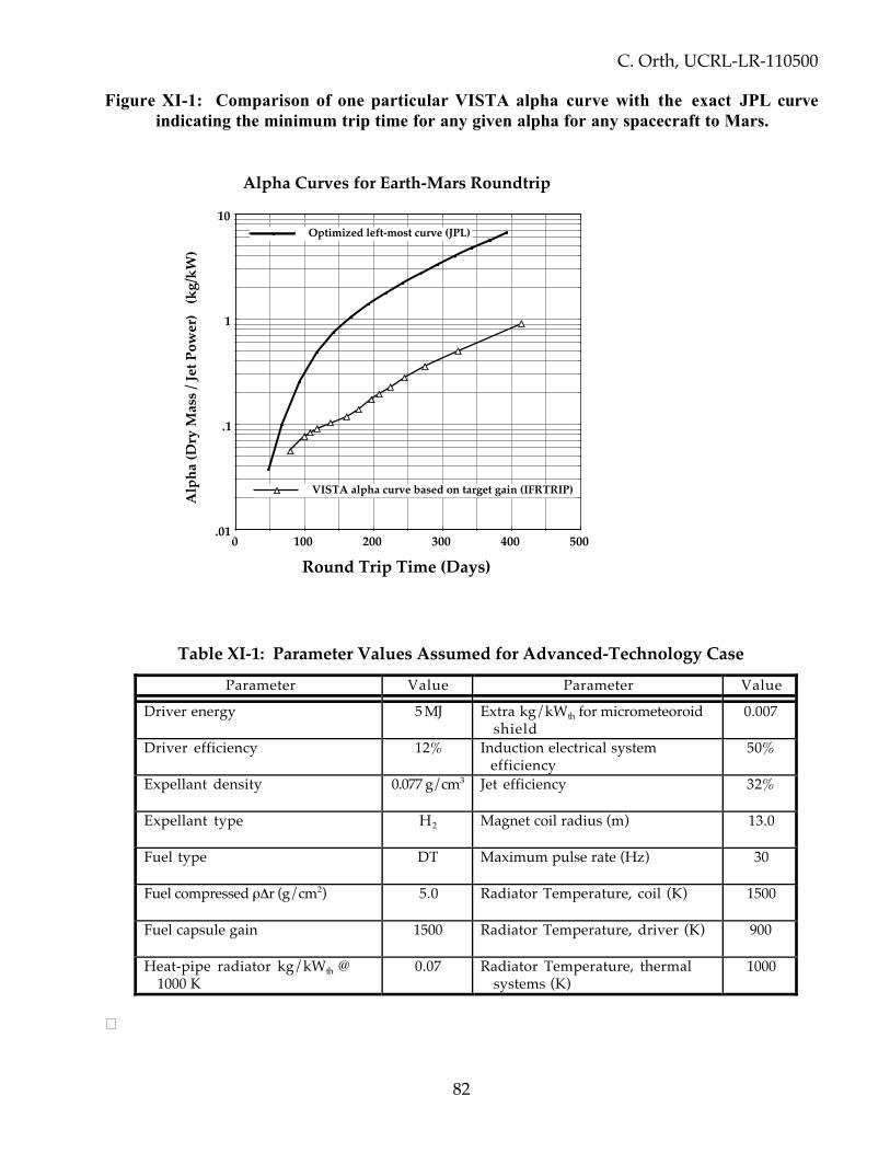
C. Orth, UCRL-LR-110500
82
Figure XI-1: Comparison of one particular VISTA alpha curve with the exact JPL curveindicating the minimum trip time for any given alpha for any spacecraft to Mars.
5004003002001000.01
.1
1
10Optimized left-most curve (JPL)
VISTA alpha curve based on target gain (IFRTRIP)
Alpha Curves for Earth-Mars Roundtrip
Round Trip Time (Days)
Alp
ha (D
ry M
ass /
Jet P
ower
) (k
g/kW
)
Table XI-1: Parameter Values Assumed for Advanced-Technology CaseParameter Value Parameter Value
Driver energy 5 MJ Extra kg/kWth for micrometeoroidshield
0.007
Driver efficiency 12% Induction electrical systemefficiency
50%
Expellant density 0.077 g/cm3 Jet efficiency 32%
Expellant type H2 Magnet coil radius (m) 13.0
Fuel type DT Maximum pulse rate (Hz) 30
Fuel compressed ρΔr (g/cm2) 5.0 Radiator Temperature, coil (K) 1500
Fuel capsule gain 1500 Radiator Temperature, driver (K) 900
Heat-pipe radiator kg/kWth @1000 K
0.07 Radiator Temperature, thermalsystems (K)
1000
�
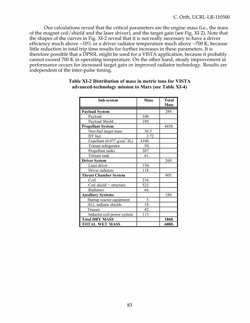
C. Orth, UCRL-LR-110500
83
Our calculations reveal that the critical parameters are the engine mass (i.e., the massof the magnet coil/shield and the laser driver), and the target gain (see Fig. XI-2). Note thatthe shapes of the curves in Fig. XI-2 reveal that it is not really necessary to have a driverefficiency much above ~10% or a driver radiator temperature much above ~700 K, becauselittle reduction in total trip time results for further increases in these parameters. It istherefore possible that a DPSSL might be used for a VISTA application, because it probablycannot exceed 700 K in operating temperature. On the other hand, steady improvement inperformance occurs for increased target gain or improved radiator technology. Results areindependent of the inter-pulse timing.
Table XI-2 Distribution of mass in metric tons for VISTAadvanced-technology mission to Mars (see Table XI-4)
Sub-system Mass TotalMass
Payload System 289.Payload 100.Payload Shield 189.
Propellant System 4458.Non-fuel target mass 36.5DT fuel 3.72Expellant (0.077 g/cm3 H2) 4100.Tritium refrigerator 50.Propellant tanks 207.Tritium tank 61.
Driver System 268.Laser driver 150.Driver radiators 118.
Thrust Chamber System 805.Coil 216.Coil shield + structure 523.Radiators 66.
Auxiliary Systems 180.Startup reactor equipment 5.ALL radiator shields 18.Trusses 42.Inductor-coil power system 115.
Total DRY MASS 1860.TOTAL WET MASS 6000.
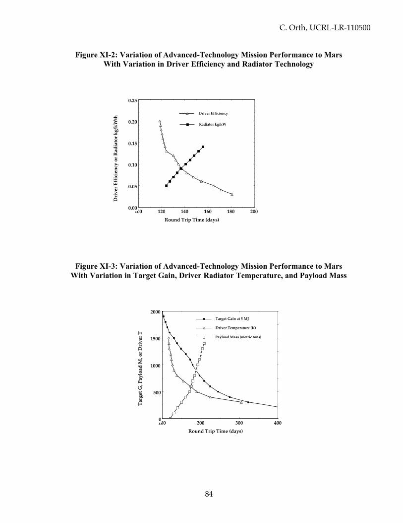
C. Orth, UCRL-LR-110500
84
Figure XI-2: Variation of Advanced-Technology Mission Performance to MarsWith Variation in Driver Efficiency and Radiator Technology
2001801601401201000.00
0.05
0.10
0.15
0.20
0.25
Driver Efficiency
Radiator kg/kW
Round Trip Time (days)
Driv
er E
ffic
ienc
y or
Rad
iato
r kg/
kWth
Figure XI-3: Variation of Advanced-Technology Mission Performance to MarsWith Variation in Target Gain, Driver Radiator Temperature, and Payload Mass
4003002001000
500
1000
1500
2000Target Gain at 5 MJ
Payload Mass (metric tons)
Driver Temperature (K)
Round Trip Time (days)
Targ
et G
, Pay
load
M, o
r Dri
ver T

C. Orth, UCRL-LR-110500
85
XI.2 Differences From Our Previous PublicationsWe have published preliminary results105 indicating Mars roundtrip mission durations
of 100 to 130 days, whereas here we report 145 days. We believe the 145-day value is moreaccurate, for the following reasons. We are now using a crew shield that is 50 tons larger foradded crew safety. We are now including the special 61-ton tank to hold tritium at 400 Kbecause of its 1/3 W/g radioactive-decay heat, which we had originally forgotten toincorporate. We are now using a detailed design of the superconducting magnet coil andcoil shield that has added 125 tons to the total thrust-chamber mass. On the other hand, weare now using a more realistic diode-pumped solid-state laser (DPSSL) driver that has abouthalf the mass as the original excimer laser. We are therefore being more accurate and moredetailed, and as one might expect, the more accurately the system is modeled, the moremass is typically required and the longer the missions become.
In our original (unrevised) paper for the ICENES’98 conference,106 we inadvertentlylabeled the 3.75 tons of DT fuel mass and the 36.7 tons of non-DT target (hohlraum) masscalculated at that time as being 40 tons of “fuel” in Table 2. This was an error (our previouspublications had used the term “target materials”). We have always claimed that 3.5 to 4.0tons of DT would be required for a roundtrip advanced-technology mission to Mars, andwe support that claim here as well. Specifically, we have not changed the amount of tritiumthat would be required for a DT-fueled mission.
XI.3 Loss in Performance due to Mass ContingenciesIt is invariably true that the launch mass for any spacecraft is always larger than that
for the original design by at least 25%. If we add a 30% contingency to the dry mass andalso account for propellant reserves and losses, then the mission duration for a roundtrip toMars becomes 183 days and the performance parameters change as shown in Table XI.3.Table XI.4 shows the breakdown of masses with such contingencies using the standardgeneric mass template adopted in 1999 by a NASA Technical Interchange Meeting. We urgeall investigators to use this type of table for reporting mass distributions.
Table XI.3 Effect of mass contingencies on performance parameters forMars Roundtrip with advanced technology
Performance Parameter Value WithMass Contingency
Value Without MassContingency
Jet efficiency (%) 32. 32.Specific impulse, Is p (s) 2.72x10⁴ 2.72x10⁴
Effective Is p, = Is p(ε jet)0.5 (s) 1.55x10⁴ 1.55x10⁴
Mass flow rate (kg/s) 1.36 1.54Thrust (N) 2.06x10⁶ 2.35x10⁶
Jet power (GW) 15.65 17.80One-way distance (cm) 2.718x10¹³ 2.423x10¹³
Alpha (kg/kW) 0.151 0.104Total wet mass (metric tons) 6500. 6000.Mission duration (days) 183. 145.

C. Orth, UCRL-LR-110500
86
Table XI.4 Distribution of mass in metric tons for VISTA’sadvanced-technology mission to Mars including contingencies
(ia. = included in value above; ib. = included in value below)
Mass Property Item MassValue
SectionSubtotal
I. Fusion EngineA. Input power systems
Input power generators (Laser Driver) 150.Power transfer systems ia.Radiators & Thermal Systems (including direct
structure/pipes, heat exchangers, coolant, pumps,refrigeration, insulation)
104.
B. Fusion Chamber Wall systems 0.Vessel Wall systemsRadiators & Thermal Systems (including direct
structure/pipes, heat exchangers, coolant, pumps,refrigeration, insulation)
C. Magnet systems (Thrust Chamber System)Magnets (Superconducting Coil) 216.Direct support structure 16.Radiation shielding 505.Thermal shielding ia.Radiators & Thermal Systems (including direct
structure/pipes, heat exchangers, coolant, pumps,refrigeration, insulation)
58.
D. Magnetic Nozzle systems 0.NozzleSystem for adding expellant in nozzleDiverter & other magnet systemsThrust vector control systemRadiators & Thermal Systems (including direct
structure/pipes, heat exchangers, coolant, pumps,refrigeration, insulation)
E. Fusion fuel systems 5.Target assemblyInjector/PositionerTritium breeding systemsRadiators & Thermal Systems (including direct
structure/pipes, heat exchangers, coolant, pumps,refrigeration, insulation)
F. Concept-specific systems 0.Other acceleration/grid systemsRadiators & Thermal Systems (including direct
structure/pipes, heat exchangers, coolant, pumps,refrigeration, insulation)
Fusion Engine Subtotal 1054.II. FluidsA. Main Propellants/Expellants
Main impulse 3835.Flight performance reserve (~1% of Main) ib.Boiloff/residuals/losses (~3% of tankable) 271
B. Stage dry (≥10% of tankable cryogenic propellants) ia.C. Adapter (~3% of Main) ia.D. Fusion fuels 3.5E. Other fluids 34.
Fluids Subtotal 4144.III. Reaction Control Systems (included in fusion fuel sys)A. Control SystemB. Reaction control fluids (~2% of Main propellant)C. Radiators & Thermal Systems (including direct structure/pipes,
heat exchangers, coolant, pumps, refrigeration, insulation)Reaction Control Systems Subtotal 0.
IV. Tanks

C. Orth, UCRL-LR-110500
87
A. Tanks (normally ~15% of propellant [incl. tritium tank = 56.) 263.B. Insulation ib.C. Refrigeration systems (including radiators) 50.D. Pumps (including radiators) ia.E. Power systems (including radiators) ia.
Tanks Subtotal 313.V. Structural ComponentsA. Primary structure (trusses, etc.) 37.B. Micrometeoroid shields (all systems) 16.C. Interface hardware ia.
Structural Components Subtotal 53.VI. Payload SystemsA. Payload 100.B. Payload radiation & thermal shields ib.C. Crew quarters ib.D. Solar-flare shields 172.E. Avionics & communications (~0.2%) ia.F. Radiators & Thermal Systems (including direct structure/pipes,
heat exchangers, coolant, pumps, refrigeration, insulation)ia.
Payload Systems Subtotal 272.VII. Power (Electrical) SystemsA. Power conversion system 90.B. Power conditioning/processing system 25.C. Energy Storage systems ia.D. Distribution systems ia.E. Direct support structure ia.F. Radiators & Thermal Systems (including direct structure/pipes,
heat exchangers, coolant, pumps, refrigeration, insulation)ia.
Power (Electrical) SystemsSubtotal
115.
VIII. Startup/Restart Power SystemA. Reactor 5.B. Electrical storage systems ia.C. Power conditioning/processing system ia.D. Radiators & Thermal Systems (including direct structure/pipes,
heat exchangers, coolant, pumps, refrigeration, insulation)ia.
Startup/Restart System Subtotal 5.
IX. Shutdown and DisposalShutdown and Disposal Subtotal 0.
X. Total Masses (metric tons)A. Total dry mass 1813.B. Total non-dry mass 4143.C. Mass growth contingency (30% of dry mass) 544.
TOTAL WET MASS at launch 6500.
XI.4 Loss in Performance due to ALL System UncertaintiesIt is important to understand that, when flight hardware is developed and a flight of
VISTA occurs, there will be uncertainties in power generation, systems masses, and systemperformance that can each affect the roundtrip time for any mission. These uncertainties aremany, including particularly the attained performance of various engine and power-systemcomponents relative to what VISTA design specifies for performance and system mass(e.g., uncertainties arising from an incomplete understanding of each system, and the masscontingencies considered in the previous section). There are also the variations fromspecified performance under actual flight conditions due to unforeseen or uncontrollable

C. Orth, UCRL-LR-110500
88
environmental factors or whatever. Of special concern is the effect of these uncertainties onjet power, radiator performance, and other system factors that can affect performancedirectly or indirectly through increases in vehicle wet mass. Rather than describe the detailsfor each system mentioned in this report, we have instead made Monte Carlo runs in whichEVERY system parameter for VISTA was randomly varied with its own Gaussiandistribution having a standard deviation of 10%. We report the effects on trip time in TableXI-5 below for Mars missions for the advanced technology case as well as for target gain of1000.
Table XI-5 Monte Carlo Variations in Roundtrip Trip Times to Mars ForVariations of 10% in EVERY System Parameter in VISTA
Planet Destination Mean Target GainMean Trip Time and
Monte CarloStandard Deviation
Mars 1500. 145 ± 18 daysMars 1000. 184 ± 17 days

C. Orth, UCRL-LR-110500
89
XII. TRAJECTORY ANALYSIS FOR MISSIONS BEYOND MARS
XII.1 General ResultsA 1989 study107 by Kathy Murray and Nathan Hoffman, two members of the
original systems analysis team, was the first step in assessing the consequences for missionsto planets beyond Mars. That study adapted VISTA for a mission to Titan, a moon ofSaturn, with the resultant spacecraft design called “Gevaltig” (which is an approximateEnglish pronunciation-equivalent for the German adjective “gewaltig” meaning “powerful,strong, mighty”). Considering Gevaltig to have only ~60% of the dry mass of VISTA, theyconcluded that 500-day roundtrips to Titan would be feasible with a 100-ton payload and1400 tons of propellant, for a total (wet) mass of 2500 tons.
Using the modern VISTA parameters, keeping the total (wet) mass near 6000 metrictons, ignoring any “spin out” to leave a planetary orbit, and using our simple systems code,we calculate the performances shown in Table XII-1 for the advanced technology case. Byrelaxing the restriction on total propellant mass, these flight times can be shortened by~25% at most.
Table XII-1 VISTA total roundtrip mission durations from Earth tothe planets for different target gains G
DestinationPlanet
RT Time (G=600)(days)
RT Time (G=1000)(days)
RT Time (G=1500)(days)
Mercury // 191 160Venus // 163 108Mars 229 184 145
Jupiter 632 486 422Saturn 1081 842 735Uranus 2093 1637 1425
Neptune 3236 2527 2134Pluto 4087 3191 2692
// Code didn’t converge.
These results differ from what we have previously published108 for the same reasons listedin Sec. XI.2. Note that the performance indicated in Table XII-1 allows roundtrip missions toPluto in a little over 7 years with advanced technology. No other technology can match thisperformance.
XII.2 Loss in Performance due to ALL System UncertaintiesIt is important to understand that, when flight hardware is developed and a flight of
VISTA occurs, there will be uncertainties in power generation, systems masses, and systemperformance that can each affect the roundtrip time for any mission. These uncertainties aremany, including particularly the attained performance of various engine and power-systemcomponents relative to what VISTA design specifies for performance and system mass(e.g., uncertainties arising from an incomplete understanding of each system, and the masscontingencies considered section XI.3). There are also the variations from specified
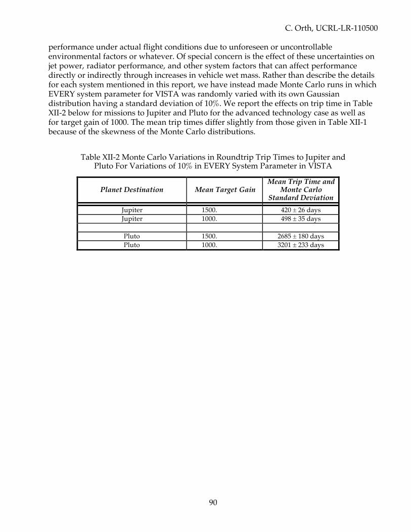
C. Orth, UCRL-LR-110500
90
performance under actual flight conditions due to unforeseen or uncontrollableenvironmental factors or whatever. Of special concern is the effect of these uncertainties onjet power, radiator performance, and other system factors that can affect performancedirectly or indirectly through increases in vehicle wet mass. Rather than describe the detailsfor each system mentioned in this report, we have instead made Monte Carlo runs in whichEVERY system parameter for VISTA was randomly varied with its own Gaussiandistribution having a standard deviation of 10%. We report the effects on trip time in TableXII-2 below for missions to Jupiter and Pluto for the advanced technology case as well asfor target gain of 1000. The mean trip times differ slightly from those given in Table XII-1because of the skewness of the Monte Carlo distributions.
Table XII-2 Monte Carlo Variations in Roundtrip Trip Times to Jupiter andPluto For Variations of 10% in EVERY System Parameter in VISTA
Planet Destination Mean Target GainMean Trip Time and
Monte CarloStandard Deviation
Jupiter 1500. 420 ± 26 daysJupiter 1000. 498 ± 35 days
Pluto 1500. 2685 ± 180 daysPluto 1000. 3201 ± 233 days

C. Orth, UCRL-LR-110500
91
XIII. MISSIONS BEYOND THE SOLAR SYSTEM
For destinations beyond the outer reaches of the solar system (i.e., beyond ~ 40 AU),the technology required for piloted missions of “reasonable” duration rapidly increases topoints beyond what is now credible—but such missions may be possible with veryadvanced technology. This is easily seen in the following table, which shows the roundtripdurations for VISTA missions to points out to 104 AU for a wet mass near 6000 metric tons.Approximately 25% reductions in flight times can be realized for missions with increasedpropellant.
Table XIII-1 VISTA roundtrip DT missions to destinations beyond Pluto
Item 100 AU 1,000 AU 10,000 AU Alpha CentauriFlight duration (yrs) 18.8 182 1,805 4.7×10⁴
Coast Velocity (km/s) 51.5 52.4 52.7 52.7Alpha (kg/kW) 0.6 2 6 31
Clearly, VISTA missions to the stars are not credible with current technology. Even at 10%of the speed of light, it takes ~80 years to go to and return from the nearest star—and it isexceedingly difficult to get any mass up to 10% of the speed of light. This is obvious fromthe following discussion.
The kinetic energy of a dry mass (payload) of M kg traveling at a fraction β of thespeed of light c is given relativistically as
T = Mc 2 11 – β 2
– 1
(23)
Noting that 1 jerk = 109 joules and Mc2 = 9×10⁷ jerks per kilogram, we can compute howlong it will take to go one-way to 104 AU as a function of β, and how much kinetic energy isinvolved, as follows:
Table XIII-2: Time and Kinetic Energy Required to Get to 104 AU
β Time to go 104 AU(years)
Kinetic energy T per kg (jerks/kg)
T/Mc2
0.001 158. 44.9 5.00×10– 7
0.005 31.6 1,123.4 1.25×10– 5
0.01 15.8 4,494.1 5.00×10– 5
0.05 3.16 1.1255 × 10⁵ 1.25×10– 3
0.1 1.58 4.5277 × 10⁵ 5.04×10– 3
1.0 0.158 infinity infinity
Obviously, β = 10– 3 is not fast enough because 158 years is longer than the lifetime of ahuman being, but β ≥ 0.005 might provide an acceptable mission duration. Also, because

C. Orth, UCRL-LR-110500
92
the maximum energy conversion efficiency for DT fusion is (340 jerks/gm)/(c2) = 0.00377, itis clear that DT fusion cannot possibly accelerate any mass to speeds greater than thatcorresponding to T/Mc2 = 0.00377, or β = 0.0866 at 100% burnup, unless multiple spacecraftstages are employed. Said differently, the T/Mc2 entry for β=0.1 is beyond the reach of DTfusion without employing multiple spacecraft stages. Such an entry is essentially beyondthe reach of antimatter propulsion as well, even though one might think that antimatter hasT/Mc2 = 1.000.
Nevertheless, with extremely advanced technology, there are ways to go to 103 to104 AU within a human lifetime. We discuss mission performance for such advancedspacecraft designs in Sec. XV.2 and Appendix A.

C. Orth, UCRL-LR-110500
93
XIV. DEVELOPMENT STRATEGY and TECHNOLOGY READINESS
XIV.1 Critical Development IssuesSome of the issues that warrant consideration in future studies are listed in Table XIV-1
below. There are only two critical issues: 1) the maximum target gain that can bedeveloped, and 2) whether the expanding plasma cools too much to make the use of amagnetic thrust chamber viable. But many other issues need consideration.
Table XIV-1 Development Issues for VISTA
Issue How critical? CommentsThrust Chamber (Coil, Shield, Inductor)Rate of decrease of plasma plume
conductivity, and effect on jet efficiencyPotentially
criticalLoss of conductivity
produces drag and lowersjet efficiency
Rate of neutron damage to containmentvessel for Li coil shield
Moderate
Rate of x-ray ablation of front surface of coilshield
Moderate
Magnitude of hoop stress in coil structure ModerateGeneral effects of 30-Hz magnetic-field
fluctuations (eddy-current heating, EMPon electronics, EMP on crew, thrust -impulse effect on hot Li liquid)
Moderate
Determination of the dissipation of thedistorted dipole magnetic field throughradiation or induced-current losses in theconducting material of the coil shield
Moderate
Optimization of the coil shield design fortritium production en route
Moderate
Determination of the minimum energymultiplication factor for neutron andgamma-ray interactions in the coil shield(M < 1.15).
Slight
The impact of Rayleigh-Taylor instabilities onthe flow of the plasma through the thrustchamber
Slight
Crew or Aircraft SafetyScattered neutron flux at cargo/crew areas ModerateImpact on high-flying aircraft of VISTA
operation in Earth orbitModerate
Structural LayoutDegree to which meteorite shield stops
particulates but transmits radiation aftermany months in space
Moderate

C. Orth, UCRL-LR-110500
94
particulates but transmits radiation aftermany months in space
Vibrational effects of 30-Hz impulsive driveon component lifetimes (added stress,fatigue, dissipation in damping elements)
Moderate
Power SystemsAccurate amount of mass and power needed
for refrigerationModerate
Detailed design of the inductor powerconversion system, especially how laserenergy can be stored for inter-pulse period(≥ 1/30 second)
Moderate
Detailed design of the inductor powerconditioning system
Moderate
Target/Target SystemsMaximum target gain G Potentially
criticalG must be larger than
several hundred to makeVISTA technologyoutperform othertechnologies
Degree of difficulty in aspherically shapingthe expellant so as to minimize neutronirradiation of spacecraft components
Minor
Optional ways to optimize the performanceusing DD or D3He fuels, and differentways to reduce the mass of tritium atlaunch time (e.g., by using DD fuel)
Moderate Use of DD can reduce thetritium inventory by 3orders of magnitude, butreduces performance
Design for the tritium storage tank usingadvanced materials
Moderate
Onboard tritium-handling procedures ModerateBest method of tritium production enroute,
and its impact on the 3.93% coil-shield solidangle
Moderate
Design of target manufacturing/assemblyarea
Moderate
DPSSL driverDetermination of the maximum operating
temperature of a DPSSL (specifically,whether the efficiency can be ≥ 6%operating at ≥600 K with a mass excludingradiators of < 300 metric tons)
Moderate
DPSSL Optics SystemsDetailed design of the final (Be) turning
mirrors (specifically to obtain a reflectivity>80%).
Moderate
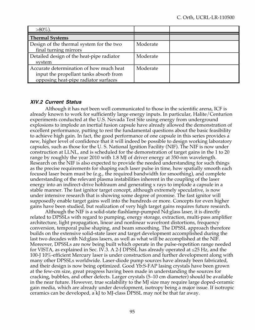
C. Orth, UCRL-LR-110500
95
>80%).Thermal SystemsDesign of the thermal system for the two
final turning mirrorsModerate
Detailed design of the heat-pipe radiatorsystem
Moderate
Accurate determination of how much heatinput the propellant tanks absorb fromopposing heat-pipe radiator surfaces
Moderate
XIV.2 Current StatusAlthough it has not been well communicated to those in the scientific arena, ICF is
already known to work for sufficiently large energy inputs. In particular, Halite/Centurionexperiments conducted at the U.S. Nevada Test Site using energy from undergroundexplosions to implode an inertial fusion capsule have already allowed the demonstration ofexcellent performance, putting to rest the fundamental questions about the basic feasibilityto achieve high gain. In fact, the good performance of one capsule in this series provides anew, higher level of confidence that it will indeed be possible to design working laboratorycapsules, such as those for the U. S. National Ignition Facility (NIF). The NIF is now underconstruction at LLNL, and is scheduled for the demonstration of target gains in the 1 to 20range by roughly the year 2010 with 1.8 MJ of driver energy at 350-nm wavelength.Research on the NIF is also expected to provide the needed understanding for such thingsas the precise requirements for shaping each laser pulse in time, how spatially smooth eachfocused laser beam must be (e.g., the required bandwidth for smoothing), and completeunderstanding of the relevant plasma instabilities inherent in the coupling of the laserenergy into an indirect-drive hohlraum and generating x rays to implode a capsule in astable manner. The fast ignitor target concept, although extremely speculative, is nowunder intensive research that is showing some degree of promise. The fast ignitor willsupposedly enable target gains well into the hundreds or more. Concepts for even highergains have been studied, but realization of very high target gains requires future research.
Although the NIF is a solid-state flashlamp-pumped Nd:glass laser, it is directlyrelated to DPSSLs with regard to pumping, energy storage, extraction, multi-pass amplifierarchitecture, light propagation, linear and nonlinear wavefront distortions, frequencyconversion, temporal pulse shaping, and beam smoothing. The DPSSL approach thereforebuilds on the extensive solid-state laser and target development accomplished during thelast two decades with Nd:glass lasers, as well as what will be accomplished at the NIF.Moreover, DPSSLs are now being built which operate in the pulse-repetition range neededfor VISTA, as explained in Sec. IV.3. A 2-J DPSSL has already operated at ≤25 Hz, and the100-J 10%-efficient Mercury laser is under construction and further development along withmany other DPSSLs worldwide. Laser-diode pump sources have already been fabricated,and their design is now being optimized. Good Yb:S-FAP lasing crystals have been grownat the few-cm size, great progress having been made in understanding the sources forcracking, bubbles, and other defects. Larger crystals (5–10 cm diameter) should be availablein the near future. However, true scalability to the MJ size may require large doped-ceramicgain media, which are already under development, isotropy being a major issue. If isotropicceramics can be developed, a kJ to MJ-class DPSSL may not be that far away.

C. Orth, UCRL-LR-110500
96
XIV.3 Realistic Development Schedule and CostsThe <$3B cost of the NIF is being paid by the terrestrial ICF Stockpile Stewardship
Program as part of the U.S. weapons (defense) programs. Much of the development cost toachieve high-gain targets will therefore be automatically covered by such agencies. Theimportant cost for VISTA is really the cost to extend the technology to space systems.
One key advantage in using a DPSSL for VISTA is that the laser is fully modular. Suchmodularity not only offers redundancy for space mission reliability, but it also considerablyreduces the cost of the development path. Another advantage is that a DPSSL is a solid-statelaser, so it has a very mature experimental base consisting of decades of experimentationon terrestrial Nd:glass lasers. It is therefore certain that a DPSSL is the lowest-risk driveroption for VISTA application.
The terrestrial (Savannah River) cost of tritium was near $30k/g, but could possibly bereduced to about $3k/g = $3B/ton for VISTA, assuming one atom of 235U can be convertedto one atom of tritium for an incremental cost of 240 $/g.109 Even at the reduced rate, the2.24 tons of tritium needed for a Mars mission would cost at least $7B. This expenditurecould be reduced by about 3 orders of magnitude if DD fuel is used with DT hotspots. It istherefore very advantageous to use DD fuel (or even D3He) rather than DT, to reduce thepurchase cost of the tritium to the order of $10M.
Figure XIV-1 shows a mid-1990’s plan to develop an attractive commercial IFEpower plant for terrestrial use. Between then and AD 2002, the objective was to down-selectthe type of driver (but a DPSSL is the most developed and hence the most reliable). Theplan indicates that the most important step after AD 2002 is to coordinate the operation ofthe National Ignition Facility (NIF), advanced driver and target R&D, and supportingtechnology R&D with results from a facility called the Integrated Research Experiment(IRE). The objectives of the IRE and these other activities are to demonstrate the integrationof IFE physics at a scale reduced from that appropriate for a power plant, and to justify thescalability of the critical technologies to the next step, which is the Engineering Test Facility(ETF). The IRE must therefore convincingly demonstrate the integrated operation of atarget chamber with a rep-ratable solid-state laser, complete with target injection andtracking, beam transport and focus, materials survivability, chamber clearing, and finaloptics protection. Most all of the dates shown in Fig. XIV-1 must now be delayed byperhaps 10 years.

C. Orth, UCRL-LR-110500
97
Figure XIV-1
Decision Year
Investment
2011
2023
2035
Decision Criteria
Scaling validation for the ETF
Net electric power, reliability, cost sufficient for power plant extrapolation
Average fusion power, reliability sufficient to qualify demo
Concept validation to qualify an IRE
Inertial Fusion Energy (IFE) Development Strategy: A Look Backward from the "End Game"
Economic (or no-go!)
Total project cost ≤$3B.
~$80-$120M/yr
Total project cost ≤$2B.
Attractive, Commercial IFE
Power Plant
IFE Demo
Engineering Test Facility
(ETF)
Integrated Research Experiment
(IRE)
National Ignition Facility
and ignition program
(Separately DOE/DP funded)
Supporting power
technologies for the Demo
Advanced driver and target R&D.
Supporting technology R&D
?
?
?
2002
$35-45M/yr Heavy Ion Beams
Diode-Pumped Solid State Lasers
Krypton Fluoride Lasers
Target design &
Technology R&D
?
Figure XIV-2 displays one possible configuration for the IRE, namely a 4-kJ 10-Hz2-ns 0.35-µm 0.5-THz-bandwidth DPSSL firing through a final optic in a transport tubeconnected to a target chamber filled with a residual gas density. Target injection could behandled by vertically dropping Xe droplets or Au targets. The laser beams striking suchtargets would generate ≥100 J/sr of x rays near the normal to provide IFE-like x-rayexposures of 7 J/cm2 in a 1-keV blackbody spectrum for samples placed less than 4 cm from

C. Orth, UCRL-LR-110500
98
the targets. Beam-target coupling could be assessed with the aid of a backlighter laser. Laseroperation at 1.05 µm and 1 kJ with 1-ps pulse widths could supply 1 PW peak power and 10kW average power for MeV x-ray generation. Various x-ray experiments could investigateliquid-metal film wall erosion and hydrodynamic instability of planar foils. Otherexperiments, coordinated with results from the NIF, could study chamber debris and gasclearing, and spin-off effects for biology, solid-state physics, plasma physics, and defensephysics. A kilojoule-class DPSSL is thus a significant component of the overall program planfor energy and defense, and hence for space power applications.
Figure XIV-2 One Configuration for a DPSSL Integrated Research Experiment (IRE)
XIV.4 Recommendation for Studies of Ways to Reduce Tritium RequirementsAs mentioned in detail in Sec. III.9, we recommend studying ways to reduce tritium
requirements at launch time so that the 2.24 metric tons of tritium needed for a Marsmission can be reduced to as little as a few kilograms of initial tritium. Otherwise, both thetime to produced the required tritium as well as the cost could easily be detriments for boththe VISTA development schedule and the environmental impact of transporting so muchtritium through the atmosphere. Significant reduction in the required tritium can beaccomplished by using DT hotspots to burn DD or D3He fuels as described in Sec. XV.1, andby developing creative concepts such as the fast ignitor target design. With small amountsof tritium required, tritium can be produced en route, and we recommend studies tooptimize the superconducting magnet shield for such a dual purpose.
Specifically, the hot (>1500 C) liquid lithium used as a coolant for thesuperconducting magnet shield, collecting a solid angle of 3.93% of the neutrons emergingfrom the fusion reactions, can be partitioned to include a tritium-breeding zone (Fig. V-2).Because the lithium breeder zone of depth ≤50 cm would not be neutronically thick (14MeV neutron mean free path is 15 cm), there would be relatively little neutron slow down;hence, the reactions would be mostly high energy ones such as 7Li(n, n' He)T rather thanthe thermal and epithermal reactions of 6Li(n, He)T. If 1% of the reactions are from the DThotspot, then all that is needed is to have 25% of the 3.93% ≈ 4% of the neutrons that strike
Target Injection (Xe liq., Au target)
Thin liquidmetal film test
Debris and gasclearing @ 10 Hz
Beamtransport thru chamber gas
Final optic
Materialssurvivablty. tests
Beam transport tubefor gas-puff & shutters
X-ray access port
Track Target
Spin-off experiments-- biology, solid-state and plasma physics
Pumps
4 kJ, 10 Hz, 2ns, 0.35 µm SSL Driver
4-kJ option
15kJ beamline
Backlightr.
Direct-drive hydrodynamic instability experiments using planar foils

C. Orth, UCRL-LR-110500
99
the lithium zone breed a triton. A tritium breeding of 0.25 atoms for each neutron to strikethe surface seems like a very reasonable outcome to expect. The tritium embedded in the Licould be extracted by cold trapping.
Detailed neutron transport calculations will be needed to optimize such a system andsee how much tritium can practically be produced. The outcome of that study will affect thetarget design by determining how much tritium is available for each target. The emphasiswill be on low-mass, low-maintenance equipment to do the tritium handling and targetfabrication. The VISTA development schedule must include such considerations.
XIV.5 Preliminary Technology Readiness AssessmentAs an aide to estimates as to when VISTA might fly, we have prepared a table
showing the technology readiness levels (TRLs) for the various systems in VISTA. The TRLdefinitions are as follows:
Technology Readiness LevelsLevel 1 -- Basic physical principles observed and reported.Level 2 -- Technology concept and/or application formulated (e.g., through feasibility studies
of concepts for engineering hardware).Level 3 – Proof of concept for analytical or experimental critical function and/or
characteristic.Level 4 – Validation of a component and/or breadboard in a laboratory environment.Level 5 -- Validation of a component and/or breadboard in the relevant (space) environment.Level 6 -- Demonstration of system/subsystem model or prototype in a relevant environment
(ground or space).Level 7 -- Demonstration of a system prototype in a space environment.
We make the following assumptions, which set the time scale for the list of TRLs. Note thatyear ZERO is merely the year chosen for VISTA to be completely flight ready, whateveryear that turns out to be (e.g., AD 2050).
Assumptions For The TRLs
• The National Ignition Facility is fully operational before year (–22).• A full system integration test of VISTA can occur in year (–3).• VISTA is flight operational by year ZERO.
The TRLs can then be estimated to occur at certain years as indicated in Table XIV-2. Weemphasize that these years are only estimates, because politics can affect how fast IFE isdeveloped. Actual dates indicate when the TRL was accomplished; otherwise, the time isspecified relative to year zero for TRL 7.
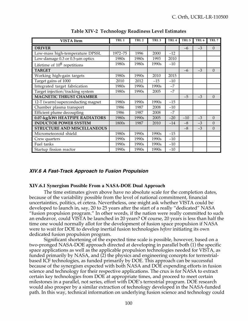
C. Orth, UCRL-LR-110500
100
Table XIV-2 Technology Readiness Level Estimates
VISTA Item TRL 1 TRL 2 TRL 3 TRL 4 TRL 5 TRL 6 TRL 7
DRIVER –6 –3 0Low-mass high-temperature DPSSL 1972–75 1996 2000 –12Low-damage 0.3 or 0.5-µm optics 1980s 1980s 1993 2010Lifetime of 108 repetitions 1980s 1980s 1990s –10TARGET –6 –3 0Working high-gain targets 1980s 1990s 2010 2015Target gains of 1000 2010 2012 –15 –10Integrated target fabrication 1980s 1990s 1990s –7Target injection/tracking system 1980s 1990s 2005 –7MAGNETIC THRUST CHAMBER –5 –3 012-T (warm) superconducting magnet 1980s 1990s 1990s –15Chamber plasma transport 1986 1987 2008 –10Efficient plume decoupling 1986 1987 2008 –70.07-kg/kWt HEATPIPE RADIATORS 1980s 1990s 2005 –20 –10 –3 0INDUCTOR POWER SYSTEM 1800s 1987 2010 –14 –8 –3 0STRUCTURE AND MISCELLANEOUS –8 –3 0Micrometeoroid shield 1980s 1990s 1990s –15Crew quarters 1990s 1990s 1990s –10Fuel tanks 1990s 1990s 1990s –10Startup fission reactor 1990s 1990s 1990s –10
XIV.6 A Fast-Track Approach to Fusion Propulsion
XIV.6.1 Synergism Possible From a NASA-DOE Dual ApproachThe time estimates given above have no absolute scale for the completion dates,
because of the variability possible from the level of national commitment, financialuncertainties, politics, et cetera. Nevertheless, one might ask whether VISTA could bedeveloped to launch in, say, 20 to 25 years after the start of a really “dedicated” NASA“fusion propulsion program.” In other words, if the nation were really committed to suchan endeavor, could VISTA be launched in 20 years? Of course, 20 years is less than half thetime one would normally allot for the development of fusion space propulsion if NASAwere to wait for DOE to develop inertial fusion technologies before initiating its owndedicated fusion propulsion program.
Significant shortening of the expected time scale is possible, however, based on atwo-pronged NASA-DOE approach directed at developing in parallel both (1) the specificspace applications as well as the applicable propulsion technologies needed for VISTA, asfunded primarily by NASA, and (2) the physics and engineering concepts for terrestrial-based ICF technologies, as funded primarily by DOE. This approach can be successfulbecause of the synergism expected with both NASA and DOE expending efforts in fusionscience and technology for their respective applications. The crux is for NASA to extractcertain key technologies from DOE at appropriate times, and proceed to meet certainmilestones in a parallel, not series, effort with DOE’s terrestrial program. DOE researchwould also prosper by a similar extraction of technology developed in the NASA-fundedpath. In this way, technical information on underlying fusion science and technology could

C. Orth, UCRL-LR-110500
101
flow in both directions between NASA and DOE to the benefit of both the space programand the terrestrial program.
XIV.6.2 Differences Between Terrestrial and Space ApplicationsThe technical and programmatic requirements for fusion propulsion have significant
differences as well as similarities from those of terrestrial energy production. Some of thedifferences conceivably could make the propulsion application of fusion easier technically,while some might make it more challenging. For example, the fusion cycle can be operatedin an open (uncontained) mode for propulsion, whereas the operating cycle mustnecessarily be closed (contained) for energy generation. This difference could potentiallylead to entirely different fusion approaches that are far easier to accomplish for propulsionthan for energy applications. In addition, the naturally occurring vacuum environment ofspace is a big advantage for many fusion systems. On the other hand, space applicationsrequire much more stringent adherence to low mass, compactness, and insensitivity tovibrations or positional precision. These factors are not direct design considerations in theDOE program except insofar as they might impact the cost of the power plant. Highlycreative innovations that might represent fundamental departures from the terrestrialprogram are therefore anticipated for the propulsion application.
In addition to the technical differences, DOE's terrestrial fusion energy program isdriven programmatically by the economics of the terrestrial cost of energy (pennies perkW-hr) and by the absence of a global energy crisis for perhaps another 50 years. The lattertends to set the time frame for DOE's technical program. On the other hand, NASA coulduse fusion propulsion right now to great advantage, if it were available. In a sense, NASA isthe more anxious customer for fusion.
Because of these differences between the terrestrial and propulsion applications, ifNASA wishes to have fusion propulsion be a reality, it needs to take full responsibility fordeveloping the technology in areas where it can (and therefore should). While doing so, itmust maintain close collaboration with DOE and other technical partners by utilizing,leveraging, synergizing, complementing, and supplementing the DOE fusion efforts andresources.
XIV.6.3 Shifting Toward a Fast-Track ApproachTable XIV-3 describes a generalized DOE roadmap for the development of inertial
fusion energy (IFE) systems for terrestrial power production using inertial confinementfusion (ICF) with a heavy-ion, KrF, or diode-pumped solid-state laser (DPSSL) driver. Thistable is based on the fact that ICF has already been shown to work for sufficient energyinput. Investigators are therefore reasonably confident that the U. S. National IgnitionFacility (NIF) can demonstrate ignition and propagating burn in DT in the laboratory nearthe threshold for ignition to establish the minimum driver energy needed for an IFE powerplant.
Because more facilities than just the main fusion facilities are required at each level todevelop supporting technologies (such as 14-MeV-neutron sources for materialsdevelopment), at least two projects (“machines”) would probably be built for each level forIFE. The total facility construction cost to develop terrestrial fusion power is thus going tobe at least $10B to $20B, and involve a duration of as much as 60 years. Consequently, toenable the launch of a fusion propulsion system in a shortened time scale, a more-efficient,enhanced route to success must be accomplished in the areas that are specific to fusionpropulsion. These areas must hence have associated “milestones” that keep the program on
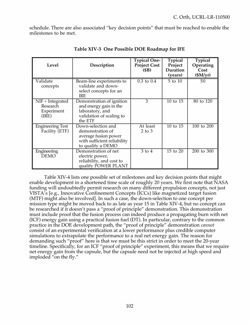
C. Orth, UCRL-LR-110500
102
schedule. There are also associated “key decision points” that must be reached to enable themilestones to be met.
Table XIV-3 One Possible DOE Roadmap for IFE
Level DescriptionTypical One-Project Cost
($B)
TypicalProject
Duration(years)
TypicalOperating
Cost($M/yr)
Validateconcepts
Beam-line experiments tovalidate and down-select concepts for anIRE
0.3 to 0.4 5 to 10 50
NIF + IntegratedResearchExperiment(IRE)
Demonstration of ignitionand energy gain in thelaboratory, andvalidation of scaling tothe ETF
3 10 to 15 80 to 120
Engineering TestFacility (ETF)
Down-selection anddemonstration ofaverage fusion powerwith sufficient reliabilityto qualify a DEMO
At least2 to 3
10 to 15 100 to 200
EngineeringDEMO
Demonstration of netelectric power,reliability, and cost toqualify POWER PLANT
3 to 4 15 to 20 200 to 300
Table XIV-4 lists one possible set of milestones and key decision points that mightenable development in a shortened time scale of roughly 20 years. We first note that NASAfunding will undoubtedly permit research on many different propulsion concepts, not justVISTA’s [e.g., Innovative Confinement Concepts (ICCs) like magnetized target fusion(MTF) might also be involved]. In such a case, the down-selection to one concept permission type might be moved back to as late as year 15 in Table XIV-4, but no concept canbe researched if it doesn’t pass a “proof of principle” demonstration. This demonstrationmust include proof that the fusion process can indeed produce a propagating burn with net(ICF) energy gain using a practical fusion fuel (DT). In particular, contrary to the commonpractice in the DOE development path, the “proof of principle” demonstration cannotconsist of an experimental verification at a lower performance plus credible computersimulations to extrapolate the performance to a real net energy gain. The reason fordemanding such “proof” here is that we must be this strict in order to meet the 20-yeartimeline. Specifically, for an ICF “proof of principle” experiment, this means that we requirenet energy gain from the capsule, but the capsule need not be injected at high speed andimploded “on the fly.”
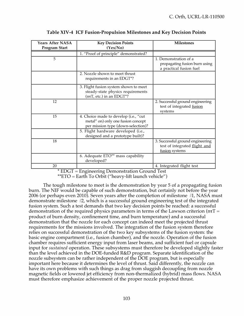
C. Orth, UCRL-LR-110500
103
Table XIV-4 ICF Fusion-Propulsion Milestones and Key Decision Points
Years After NASAProgram Start
Key Decision Points(Yes/No)
Milestones
1. “Proof of principle” demonstrated?5 1. Demonstration of a
propagating fusion burn usinga practical fusion fuel
2. Nozzle shown to meet thrustrequirements in an EDGT*?
3. Flight fusion system shown to meetsteady-state physics requirements(nτT, etc.) in an EDGT*?
12 2. Successful ground engineeringtest of integrated fusion systems
15 4. Choice made to develop (i.e., “cutmetal” on) only one fusion conceptper mission type (down-selection)?
5. Flight hardware developed (i.e.,designed and a prototype built)?
18 3. Successful ground engineeringtest of integrated flight andfusion systems
6. Adequate ETO** mass capabilitydeveloped?
20 4. Integrated flight test* EDGT = Engineering Demonstration Ground Test**ETO = Earth To Orbit (“heavy-lift launch vehicle”)
The tough milestone to meet is the demonstration by year 5 of a propagating fusionburn. The NIF would be capable of such demonstration, but certainly not before the year2006 (or perhaps even 2010). Seven years after the completion of milestone #1, NASA mustdemonstrate milestone #2, which is a successful ground engineering test of the integratedfusion system. Such a test demands that two key decision points be reached: a successfuldemonstration of the required physics parameters in terms of the Lawson criterion (nτT =product of burn density, confinement time, and burn temperature) and a successfuldemonstration that the nozzle for each concept can indeed meet the projected thrustrequirements for the missions involved. The integration of the fusion system thereforerelies on successful demonstration of the two key subsystems of the fusion system: thebasic engine compartment (i.e., fusion chamber), and the nozzle. Operation of the fusionchamber requires sufficient energy input from laser beams, and sufficient fuel or capsuleinput for sustained operation. These subsystems must therefore be developed slightly fasterthan the level achieved in the DOE-funded R&D program. Separate identification of thenozzle subsystem can be rather independent of the DOE program, but is especiallyimportant here because it determines the level of thrust. Said differently, the nozzle canhave its own problems with such things as drag from sluggish decoupling from nozzlemagnetic fields or lowered jet efficiency from non-thermalized (hybrid) mass flows. NASAmust therefore emphasize achievement of the proper nozzle projected thrust.

C. Orth, UCRL-LR-110500
104
After down-selection to one fusion concept per mission type, NASA must developthe flight hardware (i.e., “cut metal” by designing and building at least one prototype) andbe ready for milestone #3, which is a successful integrated test of the combined flighthardware and fusion systems on the ground. In the mean time, NASA must ensure that itwill have the needed heavy-lift launch vehicle or its equivalent, whatever is required, toassemble the fusion-propulsion systems in Earth orbit. Only then can the actual flight testoccur.
XIV.6.4 Fast-Track R&D RoadmapFigure XIV-3 shows the layout of the above milestones and key decision points, as
well as the interfaces between NASA and DOE for a fast-track approach. Note that the DOEtimeline at the bottom of this figure has been listed differently than in Table XIV-4. This wasdone for two reason: to combine MFE and IFE levels into one generic DOE listing, and tohighlight the features important to NASA. The nature of the lines drawn on the figureindicate the type of funding and the federal agency involved, as explained in the legend atthe bottom.
The Integrated Performance Extension box shown along the DOE timeline is acombination of the Performance Extension for MFE systems and the NIF/IRE level for ICFsystems. This box is meant to show interim achievement along the way to the developmentof an ETF facility. The construction and operation of the ETF, however, is not required forNASA to attain a launch of a fusion propulsion system, as shown. Only the inputs indicatedwith arrows proceeding from the DOE line to NASA key decision points and milestoneboxes are required for NASA to benefit from the DOE-funded research. DOE, in turn, canprosper from the accelerated NASA path, but arrows indicating this technology transfer arenot shown for reasons of clarity.
Figure XIV-3 thus shows the main interface connections between DOE and NASA, atwhich times NASA must rely on the R&D achievements of the terrestrial research. Thisfigure therefore illustrates how the DOE development of fusion for terrestrial power plantscan proceed at a more modest rate while NASA develops fusion for space propulsion alonga faster parallel path. It is important to realize to what extent this approach is dependent onthe DOE research path, and how the appropriately timed extractions of DOE technologycan offer NASA the opportunity to develop a fusion propulsion application at anaccelerated rate.

C. Orth, UCRL-LR-110500
105
Roadmap for Development of Nuclear Fusion PropulsionFigure XIV-3
Years from NASA Fusion Propulsion Program Start (Based on Launch in 20 years):
Line Legend and Symbols:
* EDGT = Engineering Demonstration Ground Test; KD = Key Decision
NASAIn-house R&D
NASA TechnicalPartners R&D
NASA-fundedDOE R&D
R&D for NASA and DOE-funded MaterialsDevelopment and
Supporting TechnologiesPrograms (Magnets,
Radiators, Injectors, etc.)
DOE Terrestrial FusionEnergy Programs
(Including Driver R&Dand Power Technologies)
Year 1 Year 5 Year 12 Year 20Year 18NASA AdvanceMission Planning
For DifferentMissions I,II,III
Determine MissionRequirements
Select Fusion SystemsA,B,C, etc. ConceptuallyMeeting Mission I,II,III
Requirements
DifferentFusion
PropulsionConcepts
A,B,C,D, …
Time,Money,Launch,Political
Constraints
PropagatingDT Burn
Demonstrated?(Milestone #1)
EDGT* NozzleMeets Thrust
Requirements?(KD #2)
EDGT* Flight FusionSystem Meets Steady-
State PhysicsRequirements (nτT, etc.)?
(KD #3)
Pass GroundEngineering Test
of IntegratedFusion Systems?(Milestone #2)
Begin R&D ForSystems
I.A, I.B, etc.,II.A, II.B, etc.
IntegratedFlightTest
(Milestone#4)
Pass GroundEngineering Test
of IntegratedFlight & Fusion
Systems?(Milestone #3)
FlightHardware
Developed?(KD #5)
AdequateETO Mass
CapabilityDeveloped?
(KD #6)Down-SelectAnd
DevelopOne
SystemPer
Mission(KD #4)
Year 15
DEMO of Reactor-Relevant DT
Burning Plasma(NIF, ITER-equiv.,
etc.)After 2006
EngineeringTest Facility
(ETF)
IntegratedPerformance
Extension[IntegratedResearch
Experiment(IRE), etc.]
Input Energy andFuel Delivery
Systems
Proof ofPrinciple
Demonstrated?(KD #1)
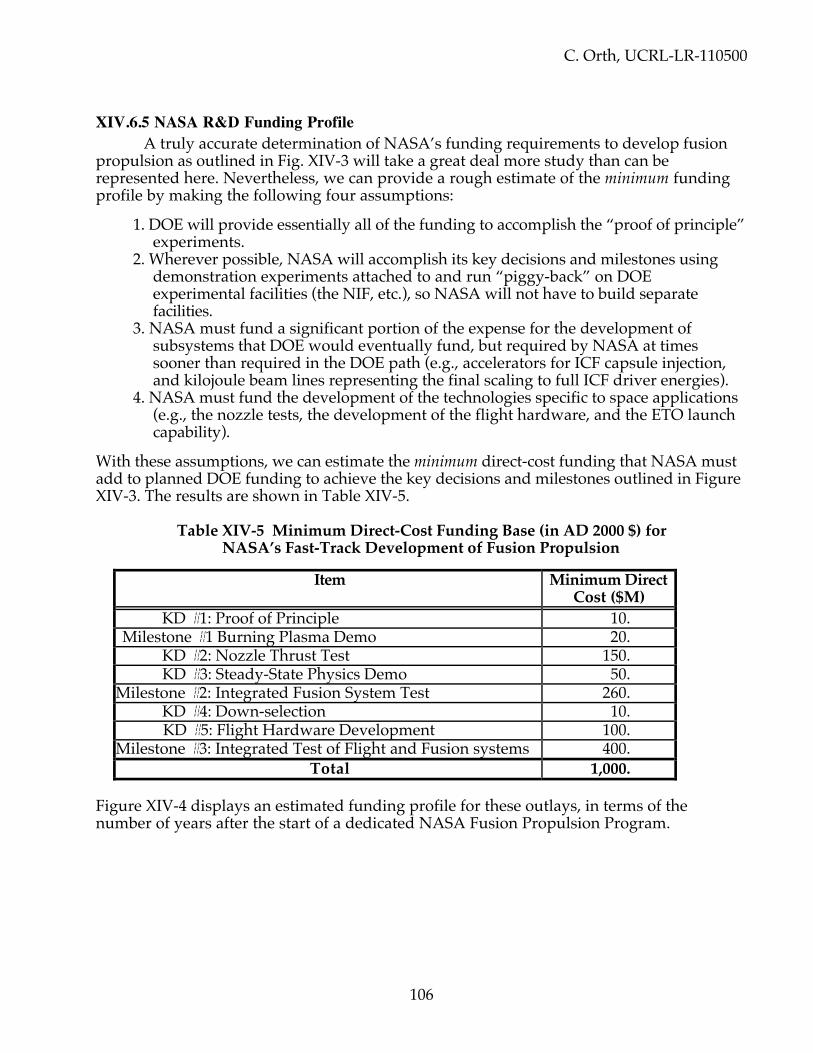
C. Orth, UCRL-LR-110500
106
XIV.6.5 NASA R&D Funding ProfileA truly accurate determination of NASA’s funding requirements to develop fusion
propulsion as outlined in Fig. XIV-3 will take a great deal more study than can berepresented here. Nevertheless, we can provide a rough estimate of the minimum fundingprofile by making the following four assumptions:
1. DOE will provide essentially all of the funding to accomplish the “proof of principle”experiments.
2. Wherever possible, NASA will accomplish its key decisions and milestones usingdemonstration experiments attached to and run “piggy-back” on DOEexperimental facilities (the NIF, etc.), so NASA will not have to build separatefacilities.
3. NASA must fund a significant portion of the expense for the development ofsubsystems that DOE would eventually fund, but required by NASA at timessooner than required in the DOE path (e.g., accelerators for ICF capsule injection,and kilojoule beam lines representing the final scaling to full ICF driver energies).
4. NASA must fund the development of the technologies specific to space applications(e.g., the nozzle tests, the development of the flight hardware, and the ETO launchcapability).
With these assumptions, we can estimate the minimum direct-cost funding that NASA mustadd to planned DOE funding to achieve the key decisions and milestones outlined in FigureXIV-3. The results are shown in Table XIV-5.
Table XIV-5 Minimum Direct-Cost Funding Base (in AD 2000 $) forNASA’s Fast-Track Development of Fusion Propulsion
Item Minimum DirectCost ($M)
KD #1: Proof of Principle 10.Milestone #1 Burning Plasma Demo 20. KD #2: Nozzle Thrust Test 150. KD #3: Steady-State Physics Demo 50.
Milestone #2: Integrated Fusion System Test 260. KD #4: Down-selection 10. KD #5: Flight Hardware Development 100.
Milestone #3: Integrated Test of Flight and Fusion systems 400.Total 1,000.
Figure XIV-4 displays an estimated funding profile for these outlays, in terms of thenumber of years after the start of a dedicated NASA Fusion Propulsion Program.
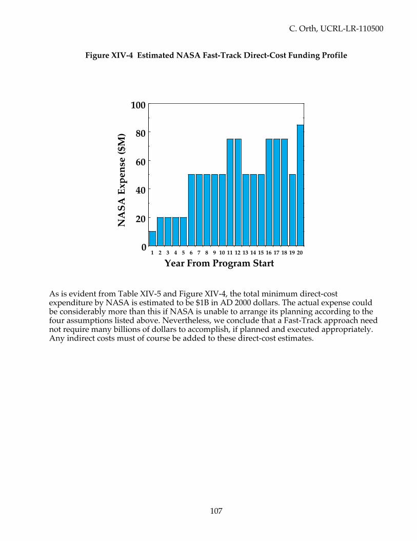
C. Orth, UCRL-LR-110500
107
Figure XIV-4 Estimated NASA Fast-Track Direct-Cost Funding Profile
As is evident from Table XIV-5 and Figure XIV-4, the total minimum direct-costexpenditure by NASA is estimated to be $1B in AD 2000 dollars. The actual expense couldbe considerably more than this if NASA is unable to arrange its planning according to thefour assumptions listed above. Nevertheless, we conclude that a Fast-Track approach neednot require many billions of dollars to accomplish, if planned and executed appropriately.Any indirect costs must of course be added to these direct-cost estimates.
1 2 3 4 5 6 7 8 9 10 11 12 13 14 15 16 17 18 19 200
20
40
60
80
100
Year From Program Start
NA
SA E
xpen
se ($
M)

C. Orth, UCRL-LR-110500
108
XV. ADVANCED-TECHNOLOGY CONSIDERATIONS
XV.1 Near-Future AdvancementsThere are many elements of advanced technology that could be considered for future
VISTA studies, as evidenced by the following questions:1. Can the expellant mass be changed during a roundtrip in order to maximize the initial
acceleration, further reduce the trip time, etc.?2. Can the shape of the expellant be adjusted to promote exhausting through the thrust chamber,
or to promote rifling of the target?3. Can at least a small part of the power generated onboard come from the low-temperature
waste heat sent to the radiator system?4. Can more advanced radiator designs be implemented?5. Can advanced fuels be used without degraded target gains?
If advanced fuels like DD or D3He can be used (#5 above), then VISTA performancewould normally be reduced as listed in Table XV-1 below, because of the reduced targetgains. These results assume a total vehicle mass of 6,000 metric tons. However, theadvanced fuels, ignited with a hot spot of DT, require three orders of magnitude lessonboard tritium, and are therefore highly desirable.
Table XV-1 Mars Missions With a 5-MJ Driver and Different Target Fuels
Item DT fusion DD fusion D3He fusionMinimum Mars roundtrip time 145 days 261 days 241 daysMass of tritium used 2237 kg 2.206 kg 2.074 kgEngine alpha (kg/kW) 0.104 0.41 0.33Vehicle mass ratio 3.23 3.97 3.96Jet power 17.8 GW 3.64 GW 4.56 GWThrust 0.23 MN 0.092 MN 0.106 MNEffective specific impulse 15.5 ks 8.1 ks 8.8 ksTotal number of emitted neutrons 1.04 × 10² 9 1.08 × 10² 9 0.15 × 10² 9
Note that there is only marginal advantage of D3He over DD—there is a significantlowering of the total neutron irradiation of nearby spacecraft, but otherwise, the twoadvanced fuels have similar performance. Therefore, if 3He proves to be difficult to obtain,as is expected, and if a suitable cryogenic state of D3He proves to be unattainable, as isexpected, there is no need to pursue the use of D3He—DD is sufficient.
Most everyone might think that antimatter fuel would be the ultimate fuel for VISTA,but this is probably not the case. Antimatter-matter annihilations release energy in the formof charged pions and neutral pions, the latter decaying into gamma rays. These pions haveenergies of ~1 GeV, and hence have very long mean free paths in material (~140 g/cm2).Thus, less than 4% of the tremendous energy produced can interact in target material to

C. Orth, UCRL-LR-110500
109
produce plasma debris for redirection by the magnetic thrust chamber. Consequently, theperformance with antimatter fuel is much worse than that with DT fuel even though themass-conversion efficiency for antimatter fuel is unity (see Table XV-2). This inability of theantimatter products to interact quickly requires a mass of antimatter (5x10² 7 antiprotons)that is enormous in comparison to even extrapolated antimatter production rates. Futurestudies may want to address how it might be possible to apply antimatter fuels to VISTA.
Table XV-2 Mars Missions With DT or Antimatter Fuel
Item DT fusion AntimatterMinimum Mars roundtrip time 145 days 220 daysFuel mass required (DT or antiprotons) 3728 kg 9.07 kg *Engine alpha (kg/kW) 0.104 0.25Vehicle mass ratio 3.23 3.71Jet power 17.8 GW 6.6 GWThrust 0.23 MN 0.13 MNEffective Isp 15.5 ks 10.0 ks
* Plus an equal mass of normal matter.
XV.2 Far-Future AdvancementsAppendix A details how the VISTA concept can be extended for extremely high
performance using extremely advanced spacecraft designs. We consider a one-way missionwith a stop at the destination, and derive scaling relationships that detail how missionperformance depends on the critical parameters. In particular, for minimum trip times, weshow the following:
1. The optimum exhaust velocity is about twice the average mission velocity (not the same velocity).2. At constant radiated power, there is a tradeoff between exhaust velocity and thrust, with higher
exhaust velocity leading to lower thrust and vice versa, because their product is proportional to theradiated power through factors that depend on technology. For example, the price of light-speedexhaust is low thrust per unit engine power, and hence low performance for missions that do notapproach light-speed.
3. Minimum-time missions always involve a coast period. Loading on more fuel to keep the engine on longeris counterproductive, because the increased mass leads to smaller accelerations and a longer trip time.
4. The ratio of coast to average velocity is exactly 3/2.5. Every minimum-time mission accelerates, coasts, and decelerates for the same fractions of the total trip
time.6. Every minimum-time mission has the same ratio of peak velocity to mean velocity.7. There is an optimum radiated power for a given distance, and the trip time increases if the ship’s power
dissipation is increased above this optimum. This counter-intuitive result occurs because the radiatormass required to dissipate the absorbed power rises faster than the increase of performance withincreased available power.
8. The optimum spacecraft design includes planar radiators. The optimum high-performance spacecrafthence looks like an incandescent (1500 K) planar object.

C. Orth, UCRL-LR-110500
110
For the extreme case of a 3-metric-ton spacecraft (including structure, engine, radiators,micro-meteoroid protection, and payload), Appendix A reveals performances of 16 days to1 AU, less than 1 year to 100 AU, 4.3 years to 1,000 AU, about 20 years to 104 AU, and 180years to Alpha Centauri.

C. Orth, UCRL-LR-110500
111
XVI. COMPARISON WITH OTHER TECHNOLOGIES
In conducting this study, it has become very evident to us that the accurate assessmentof mission durations, and hence the real viability of any concept, rests fundamentally on thedegree to which a study addresses the details of the systems involved. The more weinvestigated each subsystem in depth, the more massive VISTA became. For example,avoiding x-ray ablation of the coil shield doubled the size of the spacecraft. Making surethere was adequate protection from micrometeoroids can cut the thermal efficiency of theheat-pipe radiators in half!
We therefore have to add a large “giggle factor” to anyone suggesting a conceptualdesign based on a rocket equation and not on a detailed systems analysis, especially if theyclaim110 piloted transport roundtrip missions of fewer than 100 days to Mars withoutconsidering the concepts described in Appendix A! Nevertheless, we understand that aconcept can be released before a systems analysis is completed, so we make a few generalremarks in the following Sections comparing VISTA to alternative technologies.
XVI.1 Magnetic Confinement Fusion (MCF)We will assume for this report that MCF will eventually be demonstrated, even
though ICF has been shown to work and MCF has not. MCF then faces the followingdisadvantages, relative to ICF:
1. MCF requires more shielding masses, and will therefore probably offer lessperformance (the question being, just how much less performance).
2. Most MCF concepts rely on hybrid-plume technologies, in which additionalexpellant is added to the fusion products to increase mass flow rate and hencethrust, but these technologies will severely reduce the jet efficiency unless theadded expellant can be thermodynamically mixed with the fusion products.
There is widespread misunderstanding about item 2, so perhaps an example will help clarifythat added expellants must be thoroughly mixed (i.e., mixed to full temperatureequilibrium). The jet efficiency is the ratio of the jet power to the input power, or one-halfthe square of the thrust divided by both the mass flow rate and the input power. If thereare two distinct species involved, we obtain the following:
εjet = dm 1dt
v 1 + dm 2dt
v 22
dm 1dt
+ dm 2dt
dm 1dt
v 12 + dm 2dt
v 22(24)
Inserting 10 kg/s at 103 m/s into a stream of 10–3 kg/s at 106 m/s yields a jet efficiency ofonly 0.012 or 1%. Inserting 1 kg/s at 10 m/s into a stream of 10–3 kg/s at 105 m/s yields ajet efficiency of only 0.0012 or 0.1%. Thus, because it is usually a very difficult if notimpossible job to thermalize added expellant into a hot fast-moving plasma stream in amagnetic environment,111 most MCF concepts employing hybrid plumes may not bepractical because of the lowered jet efficiencies associated with the dual nature of the

C. Orth, UCRL-LR-110500
112
exhaust. Consequently, it is difficult if not impossible physically for a MCF concept toemploy variable specific impulse. This is not to say it cannot be done, but only that it isdifficult, and usually impossible because investigators have not realized that the jetefficiency is seriously degraded.
XVI.2 Nuclear Electric Propulsion (NEP) ConceptsFission produces neutrons and gamma rays, and these particles are difficult to form
directly into an exhaust having any significant mass-flow rate. If an indirect approach isconsidered whereby centimeters of matter are used to absorb the energy of these particles,then the exhaust temperature is usually limited to the melt temperature of the materialused to stop the particles (<1 eV). Fusion, on the other hand, has a charged plasma debris oftemperature ≥1 keV, depending on the amount of extra mass (expellant) the fusionreactions must heat up. Thus, fission-powered engines can provide high power/mass ratiosbut only low exhaust velocities for significant mass flow rates, and nuclear-electricpropulsion usually provides high exhaust velocities but only low power/mass ratiosbecause of inefficient energy conversion—but fusion can theoretically provide both highpower/mass ratios and high exhaust velocities. For single-stage self-contained spacecraftthat must go roundtrip without using questionable maneuvers (e.g., air braking in theMartian atmosphere), VISTA performance (e.g., roundtrips to Mars in ~5 months) willnecessarily be better than the performance for nuclear-thermal and nuclear-electric fissionsystems (≥ 2/3 year) because the effective exhaust temperature (i.e., specific impulse) isroughly ten times larger for high mass flow rates. In fact, as seen from Fig. XI-3, VISTAperformance is unsurpassed (< 2/3 year) for target gains ≥500.
XVI.3 Antimatter-Initiated Fission/FusionTom Nugent wrote a very nice report comparing VISTA with the so-called ion
compressed antiproton-catalyzed nuclear (ICAN) propulsion system.112 Unfortunately, theformula he was given to indicate target gain as a function of driver energy is now known tobe grossly in error. With a proper formula, the ICAN performance expectations do notcompare favorably with that for VISTA.
In general, when antiprotons are used to initiate fusion through a fission sequence sothat DT is heated to ignition temperature through the energy loss of the fission fragments,typically 101 6 to 101 7 antiprotons may be required per target.113 This is an excessive numberof antiprotons—Fermi Lab can generate only 1 microgram = 6 x 101 7 antiprotons per year.If 107 to 108 targets are required for a mission (e.g., to Mars), it could take up to 10,000 yearsfor Fermi Lab to generate enough antiprotons even if Fermi Lab’s capacity were increasedby two orders of magnitude!
For pure antimatter-matter annihilation, as opposed to antimatter-initiatedfission/fusion, the generation, transfer, and storage of antimatter are important but not theonly considerations. All pulsed propulsion methods are subject to three constraints if therocket exhaust is formed by redirection of a plasma by a magnet: (1) the energy in themagnetic field must be at least five times the total energy in the plasma for one pulse, (2)the gyroradii of the individual particles must be considerably smaller than the dimensionsof the apparatus, and (3) the dynamics (and primarily the time scale) of the redirection mustbe short enough to avoid significant Rayleigh-Taylor (interchange) instabilities. To assess

C. Orth, UCRL-LR-110500
113
the impact of these constraints for any concept, a detailed systems analysis is required,especially to determine the optimum extra mass (expellant) to be added per target tominimize trip time. Because antimatter drive can be tailored so as to have roughly the sameenergy yield per pulse as fusion schemes, and can have particulate gyroradii much smallerthan typical magnets even for MeV energies, the real dynamic limitation for pureantimatter annihilation for space propulsion may arise from the systems analysis and notfrom the above constraints. In particular, antimatter-matter annihilation products (evenwith heavy-metal admixtures) can have MeV energies, which (depending on their type) canbe orders of magnitude larger than that which will easily thermalize in expellant massesthat might optimize the mission in terms of specific impulse and other parameters. Theresult is that significantly more antiprotons are needed per target than a first considerationmight suggest. For example, for the Mars roundtrip reported in Table XV-2 with 3.6x10⁷
engine pulses, we require 9 kg of antiprotons, which is three orders of magnitude largerthan what we would expect from the numbers in the paragraph immediately above forantimatter-initiated fission/fusion. We therefore emphasize the importance of a detailedsystems analysis for any antimatter concept.
XVI.4 Orion-Type Pusher-Plate Concepts Using Nuclear ExplosionsIt is not our intent here to analyze concepts employing thermonuclear explosions set
off at a rate of up to 10 Hz behind a pusher plate in order to propel spacecraft forward, suchas in the Orion114 proposal. Nevertheless, such concepts generally have two problems:1) any significant vaporization of mass off the pusher plate will create a bimodaldistribution of propellant velocities in the plume, which can seriously reduce the jetefficiency; and 2) large-enough explosions can cause material pressures exceeding theplastic-flow rates for typical structural materials (e.g., ~2 kpsi for Al), so materialsdevelopment could be a big factor. It is difficult to say more about these concepts becausesystem studies are lacking.
XVI.5 General ConsiderationsIt is common today for people to categorize concepts based on their total liftoff (wet)
mass. After all, it would of course be more desirable to launch a so-called innovativeconfinement concept (ICC) system with a wet mass of 40 to 80 metric tons rather thanlaunch VISTA with 6,000 metric tons, especially in terms of the launch costs (which, at about$10k per pound, would be over $130B for VISTA). However, the ICCs are relatively newand in a state of infancy in terms of their development, so much physics and engineeringinformation about them is simply unknown. This makes the ICCs high risk even thoughthey may claim low mass and low cost. On the other hand, VISTA is basically a proventechnology, and it permits safe interplanetary transport in regards to the zero-gee andcosmic-radiation hazards to the astronauts. There would hence appear to be a generaltradeoff between low-mass high-risk systems and the high-mass low-risk systems. This isjust an appearance, however, because the wet masses of the ICC systems will turn out to bemuch larger than proposed once more of the details of their systems have been considered.
For example, the cosmic-radiation threat in space arises from high-energy protonsthat interact in the shell and structure of any spacecraft, thereby forming a shower of high-energy pions and other particles that can cause leukemias and other illnesses in the crew,especially for exposures longer than one year. The mean free path (mfp) of such stronglyinteracting hadrons (e.g., charged pions) is approximately 140 g/cm2 in most spacecraft

C. Orth, UCRL-LR-110500
114
materials (i.e., 123 g/cm2 in air, 140 in Al, 162 in Fe, 215 in Pb, etc.). Because the atmosphereis about 1000 g/cm2 thick (i.e., 10 meters of water, or 8 pion mfp), terrestrial humans nearsea level experience no threat from these showers because the hadrons have died outleaving only muons that interact very weakly. But in space, it is nearly impossible physicallyto protect one person from this cosmic-radiation threat without providing a shield whosethickness is equivalent to at least 2 to 3 hadron mfp (more than this is of course desirable,but there is a tradeoff between better protection and lower shield mass). A thickness of 2 to3 pion mfp corresponds to 1.0 to 1.6 meters of aluminum (or 38 to 57 cm of Pb)-----that is, atleast 3 to 4 m water-equivalent in terms of the product of thickness and density (which iswhat determines the interaction probability).
Because the cosmic-radiation threat is isotropic and ever present (unlike a solar-flarethreat corresponding to a timed event in a certain direction), the crew quarters mustnormally be surrounded by a shield for the crew to be protected from this threat.Consequently, the portion of the shield for each person can be likened to a cylindricalsection with a human-size (vertical) circumference of about 2π m = 6 m and a (horizontal)width of at least 1 m. As explained above, the thickness of this shield must be at least 3 to 4m (water-equivalent) so it is at least 2 to 3 pion mfp thick. This amount of shielding is atleast (6m)x(1m)x(3 to 4m)x(1metric ton/m3) = 18 to 24 metric tons per person. This is onereason why VISTA includes a shield mass of nearly 200 metric tons, but VISTA is also largeenough that the crew quarters can be located inside the propellant tanks, and thisminimizes the shielding mass being discussed here. And of course, the crew shield is onlyone item on the mass-breakdown list-----we certainly have to include the engine, payload,fuel, structure, radiators, etc. We may also have to include other shielding to protect thecrew from the fusion reactions, depending on the nature of the fusion engine and itsproximity to the crew. So, it would seem as though the launch mass must necessarily bemuch larger than 100 metric tons for a multiple-person crew to be safe. Consequently, anyfusion concept claiming a lift-off mass of less than 100 metric tons for a multiple-personcrew is obviously forgetting some of the important details regarding crew safety!
There are also many general physics considerations that help us develop properfigures of merit for viable fusion-powered space-propulsion concepts. One such physicsconsideration is whether a concept can ever serve the propulsion community better thanexisting technologies (e.g., fission). Specifically, consider a known fission-propulsion systemthat is economically and environmentally viable for a certain mission. Then, if the ultimatelong-range performance for a particular fusion concept cannot exceed that expected for thefission system, which is obviously based on a more mature technology than the fusionsystem, common sense tells us that we may not want to spend the time and resourcesrequired to develop that fusion system.
Consider, for example, a piloted roundtrip to Mars. A nuclear thermal rocket (orvery advanced nuclear electric propulsion system) is expected to yield a roundtrip flightduration of about 1.0 to 1.5 years, so fusion, to be useful, must do “better” in order tojustify the time and cost to develop the fusion systems. The usefulness of fusion is notmerely to provide shorter flight durations, per se, but also to help the crew avoid (1) thephysiological deterioration arising from zero-gee exposures lasting more than 100 days,and (2) the significant onset of leukemia and other cancers arising from exposures to thecosmic radiation exceeding one year. We might also consider the environmentaladvantages of fusion systems (e.g., less radioactivity hazard for material launched throughthe atmosphere). In short, there are many issues.
Nevertheless, one criterion for down-selection is whether a credible systems analysis(or even a basic physics assessment) can show that the concept could ever reach a level ofperformance better than what nuclear fission is expected to provide. This criterion can bemade quantitative by requiring that the estimated flight duration be shorter than that
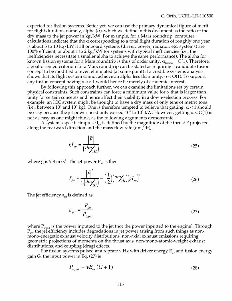
C. Orth, UCRL-LR-110500
115
expected for fission systems. Better yet, we can use the primary dynamical figure of meritfor flight duration, namely, alpha (α), which we define in this document as the ratio of thedry mass to the jet power in kg/kW. For example, for a Mars roundtrip, computercalculations indicate that the α corresponding to a total flight duration of roughly one yearis about 5 to 10 kg/kW if all onboard systems (driver, power, radiator, etc. systems) are100% efficient, or about 1 to 2 kg/kW for systems with typical inefficiencies (i.e., theinefficiencies necessitate a smaller alpha to achieve the same performance). The alpha forknown fission systems for a Mars roundtrip is thus of order unity, αfission = O(1). Therefore,a goal-oriented criterion for a Mars roundtrip can be stated as requiring a candidate fusionconcept to be modified or even eliminated (at some point) if a credible systems analysisshows that its flight system cannot achieve an alpha less than unity, α < O(1). To supportany fusion concept having α >> 1 would hence be merely of academic interest.
By following this approach further, we can examine the limitations set by certainphysical constraints. Such constraints can force a minimum value for α that is larger thanunity for certain concepts and hence affect their viability in a down-selection process. Forexample, an ICC system might be thought to have a dry mass of only tens of metric tons(i.e., between 104 and 105 kg). One is therefore tempted to believe that getting α < 1 shouldbe easy because the jet power need only exceed 104 to 105 kW. However, getting α < O(1) isnot as easy as one might think, as the following arguments demonstrate.
A system’s specific impulse Isp is defined by the magnitude of the thrust F projectedalong the rearward direction and the mass flow rate (dm/dt),
gIsp =
r F
dmdt( ) (25)
where g is 9.8 m/s2. The jet power Pjet is then
Pjet =
r F 2
2 dm dt( )=12
dmdt( ) gIsp( )2 (26)
The jet efficiency εjet is defined as
ε jet =PjetPinput
(27)
where Pinput is the power inputted to the jet (not the power inputted to the engine). ThroughPjet, the jet efficiency includes degradations in jet power arising from such things as non-mono-energetic exhaust velocity distributions, non-axial exhaust emissions requiringgeometric projections of momenta on the thrust axis, non-mono-atomic-weight exhaustdistributions, and coupling (drag) effects.
For fusion systems pulsed at a reprate ν Hz with driver energy Edr and fusion energygain G, the input power in Eq. (27) is
Pinput = νEdr (G +1) (28)

C. Orth, UCRL-LR-110500
116
where the “plus one” accounts for the driver energy itself. Using Eqs. (27) and (28) to obtainPjet and equating the result with the value in Eq. (26), we find that the specific impulse is
gIsp =2νEdr(G +1)ε jet
dmdt( ) (29)
This result demonstrates that the specific impulse is dependent on the jet efficiency. Evenfor a system with a mono-energetic axial exhaust velocity vex, the Isp is still dependent on thejet efficiency because the jet power is, from Eqs. (27) and (28),
Pjet = νEdr(G +1)ε jet =12 dm
dt( )vex2 ε jet (single vex) (30)
so, making this substitution for the numerator in Eq. (29), we getgIsp = vex ε jet (single vex) (31)
A concept’s Isp should thus include the jet-efficiency factor. It is for this reason that wereport specific impulse in this document in terms of Eq. (31), which we define to be the“effective specific impulse.”
For the general case, the quantity α can be defined using Eqs. (26) and (29) as
α =mdry
Pjet=
mdry
12
dmdt
gIsp( )2
=mdry
νEdr(G +1)ε jet (32)
where Edr is in kJ and mdry is in kg. The criterion mentioned above requiring α to be lessthan of order 1 kg/kW thus demands the fusion gain G to be larger than a minimum Gminthat can be established from Eq. (32):
G + 1( ) > Gmin +1( ) = mdry
νEdrε jet(33)
This is a key equation, because differing technologies place different restrictions on themaximum gain achievable.
At this point, we might be tempted to insert a dry mass of 104 to 105 kg for someICC having (e.g.) a reprate of 30 Hz, a driver energy of 103 kJ, and a jet efficiency of 40%.We would then obtain a result for (Gmin + 1) of 0.8 to 8, which is well within the capability ofmany ICC systems. However, this is an incorrect result—we cannot independently choosethe above numbers because they violate another constraint. To see this, and correctly applyEq. (33), we must first examine this other constraint.
Let f be the recycled power fraction. Obviously, we need f << 1; for example, thepower fPjet recycled to operate a driver with efficiency εdr (as well as other equipment) mustbe rather small compared to the jet power itself. Considering a Mars trip and using αfission =1 in the first part of Eq. (32), we find that this constraint means the following for the fusiondriver:
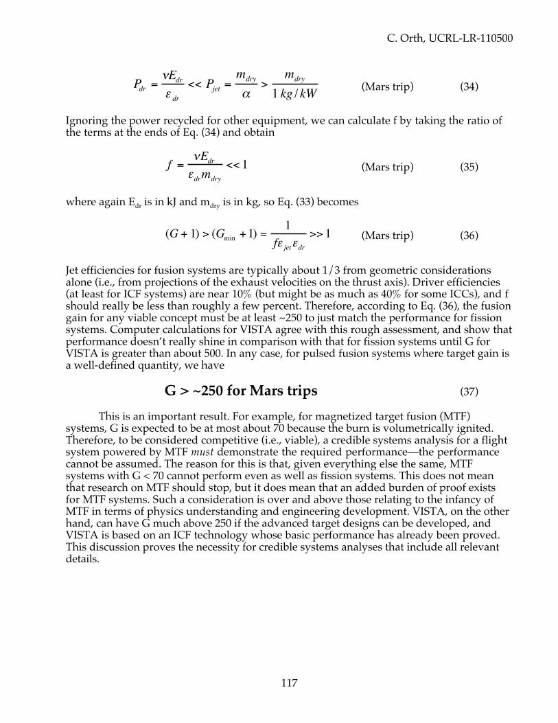
C. Orth, UCRL-LR-110500
117
Pdr =νEdrε dr
<< Pjet =mdry
α>
mdry
1 kg / kW (Mars trip) (34)
Ignoring the power recycled for other equipment, we can calculate f by taking the ratio ofthe terms at the ends of Eq. (34) and obtain
f = νEdrεdrmdry
<< 1 (Mars trip) (35)
where again Edr is in kJ and mdry is in kg, so Eq. (33) becomes
(G + 1) > (Gmin +1) =1
fε jetεdr>> 1 (Mars trip) (36)
Jet efficiencies for fusion systems are typically about 1/3 from geometric considerationsalone (i.e., from projections of the exhaust velocities on the thrust axis). Driver efficiencies(at least for ICF systems) are near 10% (but might be as much as 40% for some ICCs), and fshould really be less than roughly a few percent. Therefore, according to Eq. (36), the fusiongain for any viable concept must be at least ~250 to just match the performance for fissionsystems. Computer calculations for VISTA agree with this rough assessment, and show thatperformance doesn’t really shine in comparison with that for fission systems until G forVISTA is greater than about 500. In any case, for pulsed fusion systems where target gain isa well-defined quantity, we have
G > ~250 for Mars trips (37)
This is an important result. For example, for magnetized target fusion (MTF)systems, G is expected to be at most about 70 because the burn is volumetrically ignited.Therefore, to be considered competitive (i.e., viable), a credible systems analysis for a flightsystem powered by MTF must demonstrate the required performance—the performancecannot be assumed. The reason for this is that, given everything else the same, MTFsystems with G < 70 cannot perform even as well as fission systems. This does not meanthat research on MTF should stop, but it does mean that an added burden of proof existsfor MTF systems. Such a consideration is over and above those relating to the infancy ofMTF in terms of physics understanding and engineering development. VISTA, on the otherhand, can have G much above 250 if the advanced target designs can be developed, andVISTA is based on an ICF technology whose basic performance has already been proved.This discussion proves the necessity for credible systems analyses that include all relevantdetails.

C. Orth, UCRL-LR-110500
118
XVII. CONCLUSIONS
This study is significant for several reasons. It brought together a study team with abroad range of expertise to do a full systems analysis of a single-stage self-powered vehiclefor piloted interplanetary transport. This analysis was comprehensive in comparison tomere conceptual studies using the rocket equation; we considered detailed thermal,electrical, and fusion-target systematics as well as waste-heat radiation and micrometeoroidshielding. The result was the VISTA conceptual design and documentation showing thatVISTA is indeed a viable concept if target gains of at least 500 can be developed—no othertechnology, antimatter propulsion included, can then beat VISTA’s performance within thesolar system. In essence, VISTA brings the earlier configuration of Rod Hyde to the point ofreality, and as such, became the first study of its kind for a realistic fusion-poweredspacecraft.
In addition, this study identifies the critical issues and technology developmentsrelating to VISTA systems, and estimates the time frame for the required R&D. It identifiesthe risks for deployment of DT fusion fuels, specifically regarding tritium transport andneutron emissions, and explains how VISTA can use DD or D3He fuels if available. TheVISTA study is also the first study showing how to deliver astronauts to their destinationswithin the interplanetary medium (specifically to Mars) in a functional state free of thedeleterious physiological hazards from both zero gravity and cosmic-ray neutron-cascadeshowers. The VISTA concept even incorporates variable thrust (through variable rep rate)and variable specific impulse (through variable expellant mass per target). Payload massescan be hundreds of tons. Target gains >1000 permit exploration anywhere within theinterplanetary environment and return in missions under 10 years, and to Mars and back inabout 5 months. The VISTA concept thereby opens the solar system to safe pilotedtransport.
This study, however, is only the beginning. We have identified many areas that needclarification and/or further study to either improve VISTA’s performance or increaseconfidence in the VISTA concept. We invite and encourage other investigators to expand onthe notions introduced here.

C. Orth, UCRL-LR-110500
119
APPENDIX A: HIGH-PERFORMANCE SPACECRAFT SCALINGBy John B. Trenholme
This section considers the constraints and scaling that apply to any form of high-performance space vehicle. By “high-performance,” we mean spacecraft that can accelerateto extremely high velocities (hundreds or even thousands of kilometers per second) andcover solar-system distances in weeks or months. The requirement of high performanceleads to a system that produces extremely high power per unit vehicle mass for a longperiod of time, and to a system that reaches high velocity by expelling a total massconsiderably larger than the “dry” ship mass. As a consequence of the inevitableinefficiencies of any physical system, some of the engine power required to execute such amission becomes waste heat absorbed by the spacecraft. This waste heat must be dissipatedby radiation into space, and the combined requirements of high radiated power and largefuel mass dictate the overall configuration of the vehicle.
We will consider a simplified model that captures the scaling behavior of high-performance spacecraft without bogging us down in unimportant details. We suppose amission in free space, and do not consider the effects of planetary or solar gravity. Weignore relativistic effects in both the vehicle mission and the propulsion system. Theseeffects can be studied later, without significant change in the conclusions reached here.
Chemical energy is inadequate to propel the kinds of missions we are contemplating,because exhaust velocities comparable to the mission velocities are required (we shall seethat the optimal exhaust velocity is about twice the average mission velocity). Chemicalbonds cannot supply the energies per particle that are required to reach such velocities. Theexpulsion power therefore has to come from nuclear reactions such as fission or fusion,from matter-antimatter reactions, or from some external source (perhaps beamed power ofsome sort). We do not examine the details of the propulsion system, but instead considerthe performance of any high-energy-per-exhaust-particle system. All that we require is thatthere be enough power available to push mass to the rear at very high velocity.
Some fuel has to be “burned” to supply exhaust power (except for beamed-powersystems), but much of the “fuel” mass may well be non-energy-producing material,expelled for propulsion without itself producing power. As we shall see, it may be to ouradvantage to reduce the exhaust velocity in order to increase the thrust, by mixing inthermalized nonreactive exhaust mass (expellant) and decreasing the energy per particle.We will henceforth refer to the expelled mass as “fuel” even if much of it is inert expellant.The “fuel” used here is hence more properly termed “propellant.” The parameters of thespacecraft are as follows:
The “dry” (no-fuel) ship mass is ‘s’. Some fraction of this is useful payload, while the restis engine and auxiliary systems. Fuel mass is assumed to be carried without any tankmass – either the tanks are consumable as inert expulsion mass, or the fuel is solid andrequires no tanks. Without tanks, we need not concern ourselves with multi-stagedspacecraft.
The rocket force is constant at ‘f’. Some improvement of mission performance ispossible by using a variable-thrust engine, but we will ignore that possibility here. Theacceleration of the ship is g = f/m while the engine is on, where ‘m’ is the mass of theship plus fuel at any instant.
The mean rearward component of exhaust expulsion velocity is constant at ‘e’. There

C. Orth, UCRL-LR-110500
120
will inevitably be some distribution of speeds in the exhaust, and some distribution ofdirections. Perfection is achieved with no variation in either of these factors, and in thatideal case the mean rearward component is equal to the speed of any single exhaustparticle.
The mission we consider consists of loading a large quantity of fuel at the origin. The shipstarts its engine and accelerates steadily to high speed, burning or expelling more than halfthe fuel mass. The ship then turns off the engine and coasts at constant velocity for someperiod. It then reverses direction, restarts the engine, and decelerates until it arrives at thedestination with zero velocity. We assume fuel is available at the destination, or that theship will not be reused after the mission, and so we arrive with no fuel on board. This givesmaximum performance. The cases of a roundtrip mission or a one-way non-stop missionare simple extensions, but we do not consider them here. Note that maximum accelerationoccurs at the end of the mission with near-zero fuel, since we have assumed constant thrustand the accelerated mass is least at the end of the mission. The final acceleration is equal togF = f / s.
As mentioned above, the engine is assumed to be imperfect, in that it sprays itsexhaust over some range of angles, and in that the exhaust products have a variety ofspeeds. Consider the expulsion of some small mass ‘δm’ of exhaust during a short intervalof time. We write the mean momentum of this mass element (in a frame moving with theship) as <δm·φ·sE> = m·e. Here ‘sE’ is the speed of some portion of the exhaust, ‘φ’ is thefraction of that portion's speed directed rearward, and <angle brackets> indicate the meanof a quantity over its distribution. The mean force is then
We have used the convention that a negative sign (mass loss) indicates a push on the ship asmass decreases. The rate of fuel mass loss is thus seen to be
The power in the exhaust is the rate at which kinetic energy is added to the exhaust
Here the factor ‘α’ corrects for the difference between the mean of the square speed andthe square of the mean speed (and is not to be confused with the α in kg/kW in the maintext of this report). For a single-speed exhaust, α has its lowest possible value of 1/2, andany variation of speeds in the exhaust leads to an undesirable increase in ‘α’. For a thermaldistribution, ‘α’ is more than twice its minimum value, and is equal to
απ
TH = =1232
1085402.
f = d(me)dt
= −e dmdt
dmdt
= −fe
pE =ddtm sE2
2=e2
2sE2
e2dmdt
=αe2
β 2dmdt
=αefβ 2

C. Orth, UCRL-LR-110500
121
The factor ‘β’ corrects for the fact that not all the velocity that contributes to the kineticenergy is pointed backward to give useful thrust. The “backwardness” or collimationfactor ‘β’ is defined as the mean ratio of force component backward, to total force withoutregard to direction. It is equal to the cosine of the mean angle away from directly rearward.
Note that we are adopting the convention that Greek letters are used to representtechnology or engineering factors. The pE equation shows that the velocity-force product‘e·f’ is constant for a given exhaust power and speed-angle distribution:
e fp
= Eβα
2
This means that at constant power there is a tradeoff between velocity and thrust, withhigher exhaust velocity leading to lower thrust, and vice versa. This tradeoff will turn out tobe an important factor in maximizing mission performance, because the rocket power islimited by thermal dissipation in any physical system, and we wish to get the highestpossible performance within a constant-power limit.
The specific energy (J/kg) in the expelled mass, produced by the engine, is equal to
This quantity is a measure of our propulsion technology. Chemical engines are a poorchoice for high performance precisely because they cannot put more energy into theexhaust than that available from the breaking of chemical bonds. The result is an exhaustvelocity that is well below optimum for high-performance missions. Nuclear reactions canput some fraction of the fuel’s rest mass energy into the exhaust. Antimatter reactions can,in principle, put an even larger fraction of the rest mass energy into the exhaust. No matterwhat technology is used, however, there will be an upper limit on the exhaust velocity ‘e’ ator below the speed of light. Even if we could convert all the fuel mass to photons andsomehow collimate them rearward, we shall see that this does not give the proper balancebetween exhaust velocity and thrust unless we intend to reach a velocity near light-speed.The price of light-speed exhaust is low thrust per unit engine power, and hence lowperformance for missions that do not approach light-speed (note that momentum is hν/cfor a photon, but at least (2mT)0.5 ≈ T/(0.5v) for a particle of speed v and kinetic energy T).
The most important limitation to performance is that the ship must absorb anddissipate some finite fraction of the rocket power ‘pE’. Define ‘γ’ as the fraction of exhaustpower absorbed by the ship, so that the power ‘p’ that the ship must dissipate is
p pe f
E= =γα γβ 2
The absorbed-power fraction ‘γ’ is small if the ship is designed to intercept as little aspossible of the drive power. The requirement to dissipate the absorbed power is what setsthe performance limit of the spacecraft, since otherwise our undefined but arbitrarilypowerful engine could increase power without limit to decrease mission time. Advancedengineering will be reflected in smaller values of ‘α’ and ‘γ,’ and in larger values of ‘β.’ Afusion-driven ship (such as VISTA) will absorb heat by a number of routes, including:
pE−dmdt
=αefβ 2
ef
= αeβ
2

C. Orth, UCRL-LR-110500
122
• particle impact due to particle leakage from the magnetic field• radiation out of the fusion burn region and expelled exhaust• eddy currents induced by the large magnetic field changes during each fusion
microexplosion• dissipation of vibrational energy caused by the impulsive nature of the drive• inefficiency of the propulsion and other systems.
As we shall see, we need a refrigeration system to keep the crew and payload cool, and theship must also dissipate the waste heat from the refrigerator.
As an example suppose that the exhaust velocity ‘e’ is 1,000 km/s or about 0.3% oflight speed. The energy per particle in the exhaust is then about 5x10⁻⁶ of its rest massenergy. Assume that the thrust force is 10,000 nt (or about 2,000 lb-f), that ‘α’ is unity(thermal exhaust velocity distribution), that the fraction 'γ' of exhaust power absorbed is0.1, and that the collimation factor 'β' is 0.8. Then the power ‘p’ that must be dissipated bythe ship is
This is 1.6 GW – the power output of a large electric power plant. We must expel f/e = 10g/s of mass to get this performance (8640 kg/day). The e·f product is 10 GW.
The only presently known method of long-term, high-power dissipation in space isthermal radiation. If the radiators are black (the best case) and see only empty space, theyradiate as σθ4 when at temperature θ (recall we are using Greek letters for technologyfactors). Because of the θ4 scaling, the radiator size and mass increase rapidly as we go tolower radiating temperatures. We are strongly motivated to run at the highest possibleradiator temperature if we want high performance. As a reference point, σθ4 is about 300kW/m2 at the rather hot temperature of 1250 C (1520 °K, or yellow heat). To dissipate our1.6 GW reference case, we would need about 5,300 square meters of effective radiating area– for example, two sides of a thin square radiator over 50 meters on a side.
We shall return to the question of the radiators later, when we need to relate theship’s mass to its dissipated power. For the moment, we ignore the fact that there is arelation between ‘p’ and ‘s.’
Let us return to the mission parameters. We will review the standard equations of arocket that expels a large fraction of its initial mass. Recall that the thrust force ‘f’ is
fd me
dtedm
dt= − = −
( )
and that the equation for the rate of change of total (ship plus fuel) mass ‘m’ is
dm
dt
f
e= −
When we integrate this latter equation in time, starting with an initial mass ‘i’ for the shipplus its fuel, we get the expected constant-rate mass decrease when thrust is on:
p = αγefβ 2
=1.0 ⋅ 0.1 ⋅106 ⋅104
0.82= 1.56 ×10⁹W
m = i − fe0
t
∫ dt = i − fte

C. Orth, UCRL-LR-110500
123
Since we will end our trip when all the fuel is burned and mass equals ship mass ‘s’, the totaltime under power ‘u’ (acceleration plus deceleration) must be
ue i sf
=−( )
Let us introduce the ratio ‘R’ of initial mass (ship plus fuel) to final mass (ship only)
Ri
s=
The time under power is then given by
ue s R
f=
−( )1
Recall we accelerate, coast, and then decelerate. If we introduce the ship-plus-fuel coastmass ‘c’ as an intermediate variable, the acceleration time ‘a’ is
ae i c
f=
−( )
The deceleration time ‘d’ is similarly seen to be
de c s
f=
−( )
By Newton’s second law we have
d
d t
f
m
v=
Combined with the dm/dt equation, we have
This can be integrated to give the well-known equation relating velocity change ‘δv’ toinitial ship-and-fuel mass ‘i’ divided by remaining ship-plus-fuel mass ‘m’ at any specifictime
dvdm
= −em
= −e
i − fte
δv =−em'
i
m
∫ dm' = e ln im

C. Orth, UCRL-LR-110500
124
The total velocity change the ship is capable of making is given by
The coast (turnover) velocity ‘vc’ can be found in terms of the coast mass ‘c’ as
We are assuming force-free space, so velocity is constant at this value during coast. This isalso the maximum velocity reached during the mission.
After coasting for some period of time, we decelerate down to velocity zero at finalship-only mass ‘s,’ so we have
This zero-end-velocity condition is satisfied when c2=i·s. This lets us solve for the coastmass as the geometric mean of the initial (fuel plus ship) and final (ship only) masses
c i s=
We substitute this into the equation for coast velocity ‘vc’ and show the well-known factthat the coast velocity is just half the maximum velocity change
This motivates us to introduce the ratio ‘r’ of coast fuel-plus-ship mass to bare-ship mass(and also initial to coast fuel-plus-ship mass) as a useful intermediate variable
rcs
ic
is
R r R= = = = =2
We can write a number of trip parameters in terms of ‘r’ and get:
δvMAX = e ln is = eln R( )
vc = e ln ic
0 = v − −em
c
s
∫ dm = eln ic − e ln
cs = e ln
isc2
vc = e ln iis
= eln is
= e ln R( ) =
e ln R( )2
=δvMAX2

C. Orth, UCRL-LR-110500
125
coast mass:
coast fuel:
initial mass:
initial fuel:
coast velocity: v
initial deceleration: g
final deceleration: g
deceleration time:
initial acceleration: g
acceleration time:
power - on time: = + =( (
C
D
F
A
c sr
s r
i sr sR
s r s R
e r
frsfs
des rf
fr s
fRs
aesr r
frd
u a des r
fes R
f
=
= −
= =
= − = −
=
=
=
=−
= =
=−
=
−=
−
( )
( ) ( )
ln( )
( )
( )
) )
1
1 1
1
1
1 1
2
2
2
2
Note that ‘r’ is the ratio of acceleration to deceleration times
ra
d=
This means that acceleration must always last longer than deceleration—much longer if theinitial mass is mostly fuel.
The minimum value of ‘r’ is unity. If ‘r’ is 10 then the initial configuration is 99 partsfuel to 1 part ship (by mass) so large values of ‘r’ correspond to a tiny ship attached to ahuge fuel mass. The factor ‘es/f’ that appears several times above is the time it takes theship to dispose of an amount of fuel mass equal to its own mass.
We now want to find the distances covered during the acceleration and decelerationphases, so that we can find the coast distance and time. The acceleration distance ‘y’ isfound by integrating
dx
dm
dx dt
dm dt
e
f= =
−/
/
v
We integrate from initial mass to coast mass to get
y =−e2 ln sr
m
f
sr2
sr
∫ dm =e2sr r −1 − ln r( )[ ]
f

C. Orth, UCRL-LR-110500
126
The deceleration distance is most easily found by viewing from a frame moving at the coastvelocity ‘vc,’ so the coasting ship is at relative rest when deceleration starts. Thendeceleration moves the ship by the moving-frame distance ‘n,’ given by
Note that ‘n’ is just y/r. The total distance ‘z’ moved during deceleration is the motion ofthe frame plus the relative motion, so that
z d ne s r r r
f= + =
+ −vc
2 1 ln( )
The total distance moved under power is the sum of the acceleration and decelerationdistances
y ze s r
f+ =
−2 21( )
We make note here of the wonderful cancellation of the ‘r·ln(r)’ terms.If we don't coast at all, but immediately turn over and begin decelerating at the end
of the acceleration period, the total trip distance ‘x’ is minimal and equal to the powereddistance y+z, and so we have
xe s r
fmin
( )=
−2 21
We can solve this equation for ‘r’ to find
rxf
e sMAX = +1 2
This is the largest sensible ‘r’ value for this distance and these ship parameters. The amountof fuel corresponding to ‘rMAX’ is s·(rmax
2-1). Loading on more fuel than this amount makes itimpossible to burn all the fuel during the trip, even if power is on continuously, and soleads to lower average acceleration and a longer trip time. If we put on less fuel than thisamount, then we must coast for some of the trip. The coast velocity (for infinitesimal coastduration) corresponding to the largest sensible fuel load is
We now determine the total trip duration including a coast period of finite duration. The
coast time is the coast distance 'x-(y+z)' divided by the coast velocity ‘v,’ so the coast time is
n =−e2 ln sr
m
f
sr
s
∫ dm = −e2s r −1 − ln r( )[ ]
f
vMAX = e ln 1 +xfe2s

C. Orth, UCRL-LR-110500
127
xe s r
fe r
−−2 21( )
ln( )
The total trip time ‘t’ is the sum of the power-on and coast times
The trip time is large for values of ‘r’ close to unity, and for very large values of ‘r,’ andthere is a minimum of ‘t’ with respect to ‘r’ between these two limits. Thus there is a fuelload value that minimizes trip time. We would like to solve this transcendental equation forthe ‘r’ value that leads to minimum trip time. No analytic solution is possible, but we canfind the minimum numerically and approximate the resulting ‘r’ values. During thisprocess, it is useful to use normalized units. Define the normalized trip distance ‘j’ as
jx f
e s= 2
Define the normalized trip time ‘h’ as
ht f
e s=
The normalized trip-time equation is, in terms of ‘r’, ‘j’ and ‘h’
hj r
rr=
− −+ −
( )ln( )
11
22
For future reference, the fraction of the total trip time spent accelerating is
tt
r rj r
rr
A =−
− −+ −
( )( )ln( )
11
12
2
The fraction of the total trip time spent coasting is
tt
rj r
rr
j rj r r r
C = −−
− −+ −
=− −
− − + −1
11
1
11 1
2
22
2
2 2( )ln( )
( )( ) ( ) ln( )
The fraction of the total trip time spent decelerating is
t =es r2 −1( )
f+x − e
2s r −1( )2
feln r( )
=esf
xfe2s
− r −1( )2
ln r( )+ r 2 −1
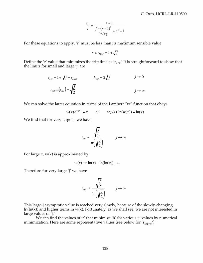
C. Orth, UCRL-LR-110500
128
tt
rj r
rr
D =−
− −+ −
11
12
2( )ln( )
For these equations to apply, ‘r’ must be less than its maximum sensible value
r r jMAX≤ = +1
Define the ‘r’ value that minimizes the trip time as ‘rOPT.’ It is straightforward to show thatthe limits for small and large ‘j’ are
We can solve the latter equation in terms of the Lambert “w” function that obeys
w x e x or w x w x xw x( ) ( ) ln( ( )) ln( )( ) = + =
We find that for very large ‘j’ we have
For large x, w(x) is approximated by
Therefore for very large ‘j’ we have
This large-j asymptotic value is reached very slowly, because of the slowly-changingln(ln(x)) and higher terms in w(x). Fortunately, as we shall see, we are not interested inlarge values of ‘j.’
We can find the values of ‘r’ that minimize ‘h’ for various ‘j’ values by numericalminimization. Here are some representative values (see below for ‘rapprox’)
ropt = 1+ j = rMAX hopt = 2 j j→ 0
ropt ln ropt( ) = j2 j→ ∞
ropt =
j2
w j2
j→ ∞
w(x)→ ln(x) − ln[ln(x)]+ ...
ropt →
j2
ln j2
j→ ∞

C. Orth, UCRL-LR-110500
129
j 0.001 0.01 0.1 1 10 100ropt 1.03114 1.09548 1.27858 1.74646 2.83640 5.32036hopt 0.064238 0.209765 0.725889 2.84425 13.4024 75.9646rmax 1.03162 1.1 1.31623 2 4.16228 11
rapprox 1.03119 1.09591 1.28072 1.74799 2.81863 5.30578
We see that the minimum-time fuel ratio ‘r’ is always less than the largest sensible value,which means that the minimum-time missions always involve a coast period. Loading onmore fuel to keep the engine on longer is counterproductive, because the increased massleads to smaller accelerations and a longer trip time.
By fitting the time-minimizing values of ‘r’ as a function of ‘j’ using a form that hasthe asymptotic behaviors given above, we can get a numerical approximation to ‘ropt’ withreasonable accuracy (max. relative error ±1%)
If greater accuracy is desired, we can use Newton-Raphson iteration of the equation thatsets the derivative of ‘h’ with respect to ‘r’ equal to zero. By starting with the aboveapproximation, three iterations give 16-digit accuracy for any value of ‘j.’ The iteration is
rr r r r j
r r rNN N N N
N N N+ =
+ − − +
+1
2 22 1 1
2 2 1
ln( ) ln( ) ( )
ln( ) ln( )
We will probably not use these minimum-time fuel-loading values in actual missions. Nearthe optimum, the trip time increases only quadratically as we decrease the fuel loading. Itsaves us fuel linearly to use less than the optimum, but only takes more time as the squareof the deviation from optimum. Therefore trips can be done with less fuel by using ‘r’values below the minimum-time values, without paying much penalty in increased triptime. The exact balance depends on the relative values of fuel and time to the persondesigning the mission.
Although we can use the above approximation to find the best loading for anyspecific power-limited values of ‘e’ and ‘f,’ it turns out that we can improve missionperformance (decrease mission time) by adjusting ‘e’ and ‘f’ while keeping their productconstant to maintain constant engine power. Remarkably, there is a global minimum timeand corresponding globally optimum fuel-loading ratio. If at all possible, we should use thisfuel loading for any mission distance, and adjust ‘e’ and ‘f’ to minimize trip time. For largedistances, we may be constrained by the maximum ‘e’ our propulsion system is capable ofproviding, but when this is not the case, every minimum-time mission starts with the samefuel load ratio. Every minimum-time mission accelerates, coasts, and decelerates for thesame fractions of the total trip time. Every minimum-time mission has the same ratio ofpeak velocity to mean velocity.
To demonstrate this extraordinary new result, we need to solve the trip equation tofind the minimum trip time. It is better to solve the transcendental trip-time equation byproceeding "backwards," by assuming a value for ‘r’ and evaluating ‘j’ and ‘h’ from thatvalue. This gives us a parametric representation for the normalized time and distance, withthe parameter being ‘r.’
rapprox =1 +j
1 + 2 ln 1 + 0.51192 j1 + 2.06834 ln(1 + 0.096966 j

C. Orth, UCRL-LR-110500
130
Given any selected value for ‘r’, we can find the value of ‘j’ for which that ‘r’ givesminimum trip time by taking the derivative of the equation for ‘h’ with respect to ‘r’ andsetting it to zero. Values of ‘j’ for which the selected ‘r’ value we started with does notminimize trip time will have non-zero slope at the selected ‘r’ value, and will be rejectedbecause their minimum-time ‘j’ values are not equal to the one we started with. We findthat
This function varies as (r-1)2 for ‘r’ near unity, and as 2[r·ln(r)]2 for very large ‘r’. Asexpected, these asymptotic j(r) behaviors correspond to the asymptotic r(j) behaviors seenabove.
By substituting the expression for ‘jopt’ into the equation for ‘h’ we find the minimumnormalized trip time to be
We now have a pair of minimum-time ‘j’ and ‘h’ values parametrically in terms of ‘r.’ Wewill next replace the normalized distance and time by the un-normalized physical valuesand determine the minimum possible trip time. Before we do that, however, we need torelate the ship’s mass to the power it dissipates.
Recall that we are assuming that power absorbed by the ship is dissipated byradiation into empty space, by radiating surfaces with black-body efficiency at absolutetemperature θ. The effective radiator area (the area that looks at empty space and not otherradiators or the Sun) must be large enough to radiate all the absorbed power, so the areamust be
Ap
RAD = σ θ 4
The radiators must not see portions of themselves if radiative efficiency is to be maximized.The only geometry that avoids self-irradiation is a near-planar or flat-plate configuration.We conclude that any high-performance spacecraft looks like an incandescent planar object.The radiators must be positioned with the sun and any nearby warm body in their plane, sothat the radiator sees only black space. We probably also want to keep ships well separated,to avoid mutual overheating.
For maximum ship performance, we want minimum mass in the radiators. Let'sassume them to be two thin, roughly square fins of side length ‘L.’ The total radiating area(two fins, with two sides each) is 4L2. The fin side length is then
Lp
=12 2θ σ
jopt(r) = 2r ln(r)[r ln(r) − r +1] + (r − 1)2
hopt = 2r2 ln(r) − (r − 1)2

C. Orth, UCRL-LR-110500
131
We want to minimize the fin mass. We'll make the fins as thin as possible, with the lowestpossible density, but it is impossible to make them arbitrarily thin compared to their lengthand width. If ‘ε’ is the ratio of thickness to side (low ‘ε’ means advanced technology) thenthe volume is 2L3ε. The structure might be made of a space-filling mass of small struts(probably pressurized with gas to increase buckling resistance) and wires, with high-performance heat pipes carrying the heat from the engine area to the surfaces. Even withmost of the volume empty, we need some fraction of solid density to do the structural andheat transport work. The formula for radiator mass we will use is
where ‘ρ’ is the average density of the radiator structure. Advanced technology allows usto decrease radiator mass by building low-ρ, low-ε radiators running at high temperatures,but the square-cube power scaling stays the same. This scaling reflects the basic fact thatradiation goes as the square of size, but mass goes as the cube. The dramatic sixth-powerdecrease of mass with radiator temperature is a strong motivation to run at very hightemperatures. The crew and cargo spaces (and perhaps portions of the engine) will have tobe refrigerated, but the rest of the ship will run hot. At the low acceleration values we willbe using, the ship can be of extremely flimsy construction – for highest performance, wewant a ship made of “incandescent tissue paper.”
Since we want minimum ship mass per unit exhaust power, we should make the restof the ship's mass small compared to mRAD. For simplicity, we assume from here on thatthe entire ship mass ‘s’ scales as mRAD above. This is the best case—fixed masses for theengine and payload will make things worse. Adding a fixed mass to the radiator mass isstraightforward, but adds unimportant complication. We now have a ship mass of
Let us return to our example ship with 1.6 GW dissipation, and assume a thinness ratio ε of0.02 and a density ρ of 100 kg/m3 (about 1/30 of solid density, depending on the materials).The radiator (and ship) mass is then
With the assumed thrust of 10,000 nt, the final (end-of-trip) acceleration is
We now return to the determination of the global optimum fuel mass ratio. We willeliminate the thrust force ‘f’ from the equations. To do so, we first consider the equation for‘j.’
mRAD =ρε4θ 6
pσ
32
s =ρε4θ 6
pσ
32
s =100 ⋅0.024 ⋅15206
1.6 ×10⁹
5.67051 ×10⁻⁸
32
=1.92 ×10⁵kg =192 tonnes
gF =1 ×10⁴nt1.92 ×105kg
= 0.052 ms2≅ 0.005g

C. Orth, UCRL-LR-110500
132
We substitute the radiator-mass-only value for the ship mass ‘s’ and write the exhaustvelocity ‘e’ in terms of the thrust force ‘f’ using the power-limit equation. The result is
We can solve this for ‘f’ to give
Next we use the normalization equation for ‘h’
Substituting the same values for ‘s’ and ‘e’ that we used in the normalization equation for ‘j,’we get
This gives us another equation for ‘f’
We can now eliminate ‘f’ by equating this equation to the one we got from the ‘j’normalization:
We now solve for the trip time ‘t’ in terms of the trip distance ‘x,’ the dissipated power ‘p,’and technology factors, times a function of the coast fuel mass ratio ‘r.’ We find:
where
t =x23p
16
223 σθ 4
αεγρβ 2
13
b(r)
j = 4xf3σ
32θ6α 2γ 2
p72β 4ρε
f = p76β
43ρ
13ε
13 j13
413x
13σ
12θ 2α23γ
23
h = 4tf2σ
32θ 6αγ
p52β 2ρε
f = p54βρ
12ε12h
12
2t 12σ34θ3α
12γ12
f = p76β
43ρ
13ε
13 j13
413x
13σ
12θ 2α23γ
23=
p54βρ
12ε12h
12
2t12σ34θ3α
12γ12
h = tfes
j = xfe2s

C. Orth, UCRL-LR-110500
133
We are using the least-trip-time values of ‘h’ and ‘j’ in the function b(r) to assure that we arealways considering an optimum trip. Given this choice, we can still vary ‘r’ to change thetrip time. It turns out that there is a minimum value of the trip time at one “magic” value of‘r.’ This particular ‘r’ gives the least possible trip time, assuming we can vary ‘e’ and ‘f’ totheir optimal values (shown below). The “magic” value comes at the minimum of b(r) withrespect to its argument:
The first factor in the numerator is positive in the interval 1 < r < ∞, and so the “magic” rvalue solves the equation
2 1 2 1 3 1 0 12 2ln( ) ln( ) ( )( ) ( )r r r r r r r− − + + − = < < ×
There is only one solution, which must be found numerically
rM = 2102526489.
The resulting minimum value of b(r) is
bM = 2 794210589.
We can now find many quantities of interest at this “magic” value of ‘r.’ The initial massratio is
RM = 4 420617637.
The trip time is
Note that the trip time increases if the ship’s power dissipation is increased. This counter-intuitive result is a consequence of the fact that the radiator mass required to dissipate theabsorbed power rises faster than the increase of performance with increased availablepower. This behavior is a consequence of the square-cube scaling law for thermal radiators.It is better to build lightweight ships of lower power if we want the highest-performancemissions. Of course, there is often a minimum size that any power system can be built at,but we should build at or near that minimum size if at all possible. Two smaller ships canalways complete a high-performance mission quicker than one larger ship, and so forth.
b(r) =hopt(r)
jopt(r)[ ]23=
2r 2 ln(r) − (r −1)2
2r ln(r) r ln(r) − r +1{ } + (r −1)2[ ]23
0 = d b(r )dr
=23[2r ln(r) +1] 2ln(r)[r 2 ln(r ) − (r −1)(2r +1)] +3(r −1)2{ }
2r ln(r)[r ln(r) − r +1] + (r −1)2{ }53
tM = 1.760242369 x23p
16
σθ 4αεγρβ 2
13

C. Orth, UCRL-LR-110500
134
The exhaust velocity is
The thrust force is
The coast velocity is
Note that the scaling of vCM is the same as eM, and only the coefficient is different. Theoptimal coast velocity is always 74% of the optimal exhaust velocity.
The average velocity is
Note that the ratio of coast to average velocity is exactly 3/2. This is true only for the“magic” fuel mass ratio – the velocity ratio is 2 for very low initial fuel loading anddecreases steadily as ‘r’ increases. The algebra to show that the “magic” value is 3/2 isstraightforward but tedious, and so we do not show it here. The optimal average velocityis always 49.5% of the optimal exhaust velocity.
The accelerations at the beginning of acceleration, at the beginning of deceleration,and at the finish of the trip are
The normalized values of the trip distance and time are
eM =1.146696057 x13 σθ 4
p16
β 2
αεγρ
13
fM = 0.8720706711 p76
x13 σθ4
β 4ερα 2γ 2
13
vCM = 0.8521553771 x13 σθ 4
p16
β 2
αεγρ
13
vAM =xtM
= 0.5681035847 x13 σθ 4
p16
β2
αεγρ
13
gAM = 0.7890939618 σθ 4
x13p
13
β 2
αεγρ
23
gDM = 1.659090957 σθ 4
x13p
13
β 2
αεγρ
23
gFM = 3.488282685 σθ 4
x13p
13
β 2
αεγρ
23

C. Orth, UCRL-LR-110500
135
j r r r r r r
h r r r
M M M M M M M
M M M M
= − + + − =
= − − =
2 1 1 2 652864291
2 1 5354708373
2
2 2
ln( ) ln( ) ( ) .
ln( ) ( ) .
The fractions of the trip time spent accelerating, coasting and decelerating are
t
t
t
AM M M
M
CM M
M
DM M
M
tr rh
trh
trh
=−
=
= −−
=
=−
=
( ).
.
.
10 4329070767
1103611944108
10 2058985125
2
The fractions of the trip distance spent accelerating, coasting and decelerating are
Let us return to our example ship, which we recall has e = 1,000 km/s, f = 10,000 nt, α = 1, γ= 0.1, β = 0.8, p = 1.6 GW, θ = 1520 K, ρ = 100 kg/m3, ε = 0.02 and s = 192,000 kg. Whatmission is this ship best suited for? The best distance, where the parameters are “magic,” isgiven by
This is about 340 A.U. The time is given by hm·e·s/f, but we use the full formula
The mission starts by loading on a fuel mass equal to
The ship then starts out with an initial acceleration of about 0.001 g. Applied over a periodof 500 days, and increasing as fuel mass is expelled, the acceleration builds up a velocity of
xAMx
=rM[rM −1 − ln(rM )]
jM= 0.2848318408
xCMx
= 1 − (rM −1)2
jM= 0.5417916162
xDMx
=rM ln(rM ) − rM +1
jM= 0.1733765430
xM =jMe2sf
=2.65286 ⋅ (106m / s) 2 ⋅1.92 ×105kg
1 ×10⁴nt≅ 5.1×10¹³m
tM = 1.760242369 (5.1×10¹³m)
23 (1.6 ×10⁹W)
16
5.67051×10−8 ⋅152041 ⋅0.02 ⋅ 0.1 ⋅100
0.82
13≅ 108 s ≅ 3.2 years
s(rM2 −1) = 192,000kg(4.4206 − 1) ≅ 660,000 kg
vCM = 0.8522 (5.1 ×10¹³m)
13 σ(1520K)4
(1.6 × 10⁹W)16
0.82
1⋅ 0.02 ⋅ 0.1 ⋅100 kg /m3
13
≅ 750 km / s

C. Orth, UCRL-LR-110500
136
This is a very high velocity by the standards of today’s chemical or ion rockets, but it is“only” 0.25% of light-speed. The ship will need extremely effective micrometeoroiddefenses at this coast velocity.
The ship coasts for 420 days, and then turns over and begins decelerating at 0.002 g. It hasalready covered 83% of the total distance. After 240 days of deceleration, it comes to a stopwith a final deceleration of 0.005 g. The ship is now about ten times as far from its startingpoint as the radius of the solar system. Getting this far in a little over three years is indeed ahigh-performance mission.
How do ship designs vary with the mission distance? Realizing that “small is beautiful” ifwe want high performance, let’s consider ships that dissipate only 100 MW with othertechnology factors set to the values we have been using:• Exhaust velocity distribution factor α = 1 (thermal distribution)
• Exhaust angular distribution factor β = 0.8
• Exhaust power absorption fraction g = 0.1 (exhaust useful power 1 GW)• Radiator fin temperature θ = 1520 °K
• Radiator fin thickness-to-length ratio ε = 0.02
• Radiator fin average density ρ = 100 kg/m3
With these values, the radiator (and ship) mass is
It will be a considerable challenge to build a 1 GW engine that has a mass small compared to3 tons, but we will assume it can be done. The payload also has to be small compared to 3tons. The ship designs will be optimized for a variety of distances from 1 A.U. to 10,000A.U., giving the following results:
Distance(A.U.)
time(one way)
exhaust vel.(km/s)
thrust(nt)
coast vel.(km/s)
max. accel.(g)
1 15.67 days 222.9 2645 165.6 0.0898410 72.77 days 480.2 1228 356.9 0.04170100 337.8 days 1035 569.9 768.9 0.019361000 4.293 years 2229 264.5 1656 0.00898410000 19.93 years 4802 122.8 3569 0.004170270000 179.3 years 14410 40.93 10710 0.00139
The last row corresponds to a mission to Alpha Centauri, and requires us to put almost0.2% of their rest mass energy into the exhaust particles. These designs are audacious, but inreturn for design audacity, they give extremely high performance. They also give us a goodfeel for the maximum performance we might achieve with advanced nuclear-energypropulsion systems. Improving on the performance in the table will require us to build
s =100 ⋅0.024 ⋅15206
108
5.67051 ×10⁻⁸
32
= 3002.45 kg ≅ 3 tonnes

C. Orth, UCRL-LR-110500
137
very small ships, run at extremely high radiator temperatures, or create designs thatintercept and dissipate very small percentages of the engine power. The largest leverage isin radiator temperature, since trip time goes inversely with the square of this quantity, butrunning at 1500 °K is already a very difficult feat. We also see that any high-performancedesign requires high exhaust velocity, since optimal coast velocity is 74% of exhaustvelocity. The performance drop-off for lower exhaust velocity is not abrupt, however, andthere is some flexibility in the choice of this quantity.

C. Orth, UCRL-LR-110500
138
ACKNOWLEDGMENTS
The work at LLNL was performed under the auspices of the U.S. Department ofEnergy by the University of California, Lawrence Livermore National Laboratory, undercontract number W-7405-Eng-48. We thank the 1987 systems-study team consisting of GailKlein and Joel Sercel of JPL, Nathan Hoffman and Kathy Murray ofRockwell/Rocketdyne/ETEC, and Franklin Chang-Diaz of NASA/JSC, because thisdocument would never have existed without their help. We thank Bill Hogan and MaxTabak of LLNL, and Tien-Fang (Ted) Yang of MIT for helpful suggestions and commentsduring the early phases of the systems analysis. We thank Hoppy Price of JPL for drawingthe VISTA layout, and Stan Krauthamer of JPL for investigating advanced power-conditioning systems. We thank Carl Sauer and Andrey Sergeyevsky of JPL for running theNASTRAN code for Mars missions. We thank Katie Barhydt, Alok Chatterjee, and JayantSharma of JPL for helpful suggestions. We thank Tom Trelenberg for investigating tritiumhazards, and for computer calculations relating to alpha curves. We thank John Trenholmefor writing Appendix A, and Ralph Moir for critically reading the manuscript.
REFERENCES
1 R. A. Hyde, "A Laser Fusion Rocket for Interplanetary Propulsion," UCRL-88857, University of California,
Livermore, CA (1983), and the 34th International Astronautical Federation, held in Budapest, Hungary,10-17 October 1983.
2 Sally K. Ride, “Leadership and America’s Future in Space,” NASA, Report to the Administrator (August1987).
3 Sally K. Ride, ibid.4 K. Boyer and J. D. Balcomb, "System studies of fusion powered propulsion systems," AIAA Paper No. 71-636
(June 1971).5 “Manned Mars Missions: A Working Group Report,” ed. by Michael B. Duke and Paul W. Keaton, NASA
Report M001 (May 1986); and Nate Hoffman, ETEC, private communication (blood problems in zerogravity).
6 Ibid.; and Nate Hoffman, ETEC, private communication (leukemias).7 Jeffery Kahn, “Cosmic Ray Questions,” LBL Research Review, Vol. 16, No. 3, p. 2 (Fall/Winter 1991).8 C. Nance, "Nuclear pulse propulsion," IEEE Trans. on Nuclear Sci. NS-12, No. 1, (1965), 177-182; and F. J.
Dyson, "Death of a project," Science, 149 (1965), 141-144.9 R. Hyde, L. Wood, and J. Nuckolls, "Prospects for rocket propulsion with laser-induced fusion
microexplosions," AIAA Paper No. 72-1063 (December 1972).10 R. Forward, “Mars-Earth Rapid Interplanetary Tether Transport (MERITT) System: I. Initial Feasibility
Analysis,” 35th AIAA/ASME/SAE/ASEE Joint Propulsion Conference, 20–24 June 1999, Los Angeles, CA,Paper AIAA 99-2151.
11 J. D. Balcomb, et al., "Nuclear pulsed space propulsion systems," LA-4541-MS, Los Alamos ScientificLaboratory, Los Alamos, NM (November 1970).
12 E.g., Bill Wagstaff, “A Spaceship Named Orion,” Air & Space, Smithsonian Institute (Oct./Nov. 1988).13 R. Hyde, L. Wood, and J. Nuckolls, "Prospects for rocket propulsion with laser-induced fusion
microexplosions," AIAA Paper No. 72-1063 (December 1972).14 F. Winterberg, "Rocket propulsion by thermonuclear micro-bombs ignited with intense relativistic electron
beams," Raumfahrtforschung 15 (1971), 208-217; and Proceedings of the International School of Physics“Enrico Fermi,” Physics of High Energy Density (NY: Academic Press, 1971), pp. 395–396.
15 A. R. Martin, ed., "Project Daedalus: The Final Report on the B.I.S. Starship Study," J. British
C. Orth, UCRL-LR-110500
139
Interplanetary Society, Supplement (1978).
16 R. A. Hyde, "A Laser Fusion Rocket for Interplanetary Propulsion," UCRL-88857, University ofCalifornia, Livermore, CA (1983), and the 34th International Astronautical Federation, held in Budapest,Hungary, 10-17 October 1983.
17 B. G. Cour-Palais, "Meteoroid Environment Model -1969 (Near Earth to Lunar Surface)," NASA SP 8013,1969.
18 Norman R. Schulze, Fusion Energy for Space Missions in the 21st Century, NASA Technical Memorandum4298, p. 7-22 (August 1991).
19 Norman R. Schulze, ibid., p. 7-24.20 Norman R. Schulze, ibid., p. 7-24.21 J. F. Santarius, “Magnetic Fusion for Space Propulsion,” Fusion Technology, Vol. 21, p. 1794 (May 1992).22 J. F. Santarius, ibid.23 Norman K. Schulze, Fusion Energy for Space Missions in the 21st Century: Executive Summary, NASA
Technical Memorandum 4297 (Aug. 1991).24 Max Tabak, J. Hammer, M. Glinsky, W. Kruer, S. Wilks, J. Woodworth, E. M. Campbell, M. Perry, and R.
Mason, “Ignition and High Gain with Ultra-Powerful Lasers,” Physics of Plasmas, Vol. 1 # 5, pp.1626–1634 (1994); and Max Tabak, private communication (1998).
25 R. A. Sacks and D. H. Darling, "Direct Drive Cryogenic Capsules Employing DT Wetted Foam," UCRL-94381, University of California, Livermore, CA (April 1986), and "Direct Drive Cryogenic ICF CapsulesEmploying D-T Wetted Foam," Nuclear Fusion, 27, #3 (1987) 447-452.
26 R. A. Sacks and D. H. Darling, ibid.27 Sümer Sahin, Haci Mehmet Sahin, and Adnan Sozen,”Evaluation of the Neutron and Gamma-ray
Heating in the Radiation Shielding and Magnet Coils of the VISTA Spacecraft,” Fusion Technology, 33(July 1998) 418–434; and Sümer Sahin, Haci Mehmet Sahin, and Eyüp öztürk, “Reduced RadiationShielding for the Magnet Coils of the VISTA Spacecraft,” Ninth International Conference on EmergingNuclear Energy Systems (ICENES’98), Tel-Aviv, Israel, June 28 – July 2, 1998, 1 (1998) 312–319; and SümerSahin and Haci Mehmet Sahin, “Radiation shielding mass saving for the magnet coils of the VISTAspacecraft,” Annals of Nuclear Energy, 26 (1999) 509-521; and Sümer Sahin and Haci Mehmet Sahin,“Optimization of the radiation shielding mass for the magnet coils of the VISTA spacecraft,” Annals ofNuclear Energy, 28 (2001) 1413-1429; and Sümer Sahin, Haci Mehmet Sahin, and AbdulmuttalipSahinaslan, “Reduced Shielding Mass for the VISTA Spacecraft,” Arabian Journal for Science andEngineering, 27 (2002) 187-196.
28 Charles D. Hendricks, "Automated Laser Fusion Target Production Concept," UCRL-80209, University ofCalifornia, Livermore, CA (4 October 1977); C. D. Hendricks and W. L. Johnson, "Power Plant Production ofInertial Confinement Fusion Targets," UCRL-52539, University of California, Livermore, CA (15 February1979); C. D. Hendricks and W. L. Johnson, "Electrostatic Levitation, Control, and Transport in High-RateLow-Cost Production of Inertial Confinement Fusion Targets," UCRL-82752, University of California,Livermore, CA (25 May 1979); Wayne L. Johnson and Charles D. Hendricks, "Electrostatic Levitation andTransport of Laser Fusion Targets," UCRL-83981, University of California, Livermore, CA (22 May 1980); J.W. Sherohman and C. D. Hendricks, "A Target Factory in Perspective," UCRL-83470, University ofCalifornia, Livermore, CA (11 April 1980); and J. W. Sherohman and W. R. Meier, "A Parametric Study ofa Target Factory for Laser Fusion," UCRL-84264, University of California, Livermore, CA (8 October 1980).
29 R. W. Petzoldt, “IFE Target Injection and Tracking Experiment,” Fusion Technology, 34 (1998) 831-839; andR. W. Petzoldt, R. W. Moir, “Target Injection and Tracking for Inertial Fusion Energy,” University ofCalifornia, Lawrence Livermore National Laboratory, Report UCRL-JC-122017 and InternationalSymposium on Heavy Ion Inertial Fusion, Princeton, NJ (Sept. 6–9, 1995); also see M. J. Monsler, "LaserFusion: An Assessment of Target Injection, Tracking, and Beam Pointing," UCRL-80563, University ofCalifornia, Livermore, CA (5 June 1978), and CONF-780508, Procs. of the 3rd Topical Meeting on theTechnology of Controlled Nuclear Fusion, 9-11 May 1978, Santa Fe, NM, Vol. 2, p. 1186.
30 John H. Pitts, "Heat-Transfer Limitations on Targets Used in ICF Reaction Chambers," UCRL-85975,University of California, Livermore, CA (12 October 1981), and IEEE Pub. No. 81CH1715-2 NPS, 9thSymposium on Engineering Problems of Fusion Research, 26-29 October 1981, Chicago, IL, Vol. I, p. 676.
31 R. W. Petzoldt, “Membrane Support for Accelerated Fuel Capsules for Inertial Fusion Energy,” FusionTechnology, 30 (1996) 73-82.
C. Orth, UCRL-LR-110500
140
32 R. W. Petzoldt and R. W. Moir, “Membrane Support of Accelerated Fuel Capsules for Inertial FusionEnergy,” Fusion Technology, 30 (Sept. 1996) 73–82.33 John H. Pitts, ibid.34 M. J. Monsler, "Laser Fusion: An Assessment of Target Injection, Tracking, and Beam Pointing," UCRL-
80563, University of California, Livermore, CA (5 June 1978), and CONF-780508, Procs. of the 3rd TopicalMeeting on the Technology of Controlled Nuclear Fusion, 9-11 May 1978, Santa Fe, NM, Vol. 2, p. 1186.
35 M. D. Rosen, J. D. Lindl, and A. R. Thiessen, "Simple Models of High-Gain Targets--Comparisons andGeneralizations," UCRL- 50021-83, University of California, Livermore, CA (June 1984), pp. 3-5 to 3-9.
36 M. D. Rosen, ibid.37 J. D. Lindl, R. O. Bangerter, J. W-K. Mark, and Yu-Li Pan, "Review of Target Studies for Heavy Ion
Fusion," UCRL-94382, University of California, Livermore, CA (24 October 1986) and Procs. of theInternational Symposium on Heavy Ion Fusion, Washington D.C. (Fig. 3).
38 John Lindl, Physics of Plasmas, Vol. 2, No. 11 (1995), p. 3969, Eq. (100).39 Max Tabak, private communication, July 1998.40 Max Tabak, private communication, July 1998.41 M. Tabak, “What is the Role of Tritium-Poor Fuels in ICF?”, Nuclear Fusion, 36, No. 2 (1966), p. 147.42 M. Tabak, Nuclear Fusion, ibid.43 Energy from Inertial Fusion (Vienna: International Atomic Energy Agency, 1995), p. 430.44 Sümer Sahin, et al., ibid.45 R. O. Bangerter, Lawrence Livermore National Laboratory, private communication (1986).46 J. Swingle, Lawrence Livermore National Laboratory, private communication (1986).47 D. Harris, Los Alamos National Laboratory, private communication (1986).48 J. H. Nuckolls, Lawrence Livermore National Laboratory, private communication (1987).49 C. D. Orth, S. A. Payne, and W. F. Krupke, “A Diode Pumped Solid State Laser Driver for Inertial Fusion
Energy,” Nuclear Fusion, 36, #1 (1996) 75-116.50 C. D. Marshall, L. K. Smith, R. J. Beach, M. A. Emanuel, K. I. Schaffers, and S. A. Payne, “Diode pumped
ytterbium-doped Yb:Sr5(PO4)3F laser performance,” IEEE J. Quantum Electronics, 32, #4 (1996) 650 (andibid., 1995 ASSL Conference Proceedings).
51 C. D. Marshall, L. K. Smith, S. Sutton, M. A. Emanuel, K. I. Schaffers, S. Mills, S. A. Payne, W. F.Krupke, and B. H. T. Chai, “Diode-pumped gas-cooled-slab laser performance,” OSA Trends in Optics andPhotonics on ADVANCED SOLID STATE LASERS, 1, Ed. S. A. Payne and C. R. Pollock, Topical MeetingJanuary 31 – February 2, 1996, San Francisco, CA, Optical Society of America (1996) 208–212.
52 C. Orth, R. Beach, C. Bibeau, E. Honea, K. Jancaitis, J. Lawson, C. Marshall, R. Sacks, K. Schaffers, J.Skidmore, S. Sutton, “Design modeling of the 100-J diode-pumped solid-state laser for Project Mercury,”SPIE Proceedings, Solid State Lasers VII, 23–30 January 1998, San Jose, CA, 3265, 114–129.
53 C. D. Orth, S. A. Payne, and W. F. Krupke, ibid.54 Charles D. Orth, Joshua E. Rothenberg, Stephen A. Payne, Howard T. Powell, “Progress at LLNL Toward
DPSSL-Driven Inertial Fusion Energy,” Current Trends in International Fusion Research—Proceedings ofthe Third Symposium Edited by E. Panarella. NRC Research Press, National Research Council of Canada,Ottawa, ON K1A OR6 Canada (1999).
55 C. Orth, R. Beach, C. Bibeau, E. Honea, K. Jancaitis, J. Lawson, C. Marshall, R. Sacks, K. Schaffers, J.Skidmore, S. Sutton, “Design modeling of the 100-J diode-pumped solid-state laser for Project Mercury,”SPIE Proceedings, Solid State Lasers VII, 23–30 January 1998, San Jose, CA, 3265, 114–129.
56 C. D. Marshall, L. K. Smith, R. J. Beach, M. A. Emanuel, K. I. Schaffers, and S. A. Payne, “Diode pumpedytterbium-doped Yb:Sr5(PO4)3F laser performance,” IEEE J. Quantum Electronics, 32, #4 (1996) 650 (andibid., 1995 ASSL Conference Proceedings).
57 Eric C. Honea, Jay A. Skidmore, Barry L. Freitas, Everett Utterback, and Mark A. Emanuel, “Modelingchirp and sag effects in high-peak laser-diode-bar pump sources for solid-state lasers,” ADVANCEDSOLID STATE LASERS (2–4 Feb. 1998, Coeur d’Alene, Idaho), OSA Trends in Optics and Photonics, 19(1998) 326–332.
58 R. A. Hyde, "A Laser Fusion Rocket for Interplanetary Propulsion," UCRL-88857, University ofCalifornia, Livermore, CA (1983), and the 34th International Astronautical Federation, held in Budapest,Hungary, 10-17 October 1983.
59 D. Milam, Lawrence Livermore National Laboratory, private communication (July 1986).

C. Orth, UCRL-LR-110500
141
60 D. Milam, ibid.61 D. Milam, ibid.62 Robert Bieri, “Grazing Incidence Metal Mirrors as a Solution to the Problem of Neutron Damage to Final
Optics for a Laser Driver,” University of California, Lawrence Livermore National Laboratory memoICFR-LLNL-89-7 (April 4, 1989); W. R. Meier, R. L. Bieri, et al., “OSIRIS and SOMBRERO InertialConfinement Fusion Power Plant Designs, Volume 2, Designs, Assessments, and Comparisons,” W. J.Schafer Associates Report WJSA-92-01, DOE/ER/54100–1 (March 1992) esp. pp. 3–142 to 3–144; and“Inertial Fusion Energy Reactor Design Studies, PROMETHEUS-L, PROMETHEUS-H, Final Report,”McDonnell Douglas Aerospace Report MDC 92E0008, DOE/ER-54101 (March 1992) esp. pp. 4–85 to 4–86 and6.5.1–46 to 6.5.1–62.
63 R. W. Moir, “Grazing incidence liquid metal mirrors (GILMM) as the final optics for laser inertial fusionenergy power plants,” University of California, Lawrence Livermore National Laboratory Report UCRL-ID-134612; and R. W. Moir, “Grazing incidence liquid metal mirrors (GILMM) for radiation hardened finaloptics for laser inertial fusion energy power plants,” University of California, Lawrence LivermoreNational Laboratory Report UCRL-JC-132875 and the Fifth International Symposium on Fusion NuclearTechnology (ISFNT-5), Rome, Italy (September 19–24, 1999).
64 R. A. Hyde, "A Laser Fusion Rocket for Interplanetary Propulsion," UCRL-88857, University ofCalifornia, Livermore, CA (1983), and the 34th International Astronautical Federation, held in Budapest,Hungary, 10-17 October 1983.
65 R. A. Hyde, ibid.66 R. A. Hyde, ibid.67 E.g., M. K. Wu, et al., "Superconductivity at 93 K in a New Mixed-Phase Y-Ba-Cu-O Compound System at
Ambient Pressure," Phys. Rev. Lett. 58, No. 9 (2 March 1987) 908 .68 R. A. Hyde, "A Laser Fusion Rocket for Interplanetary Propulsion," UCRL-88857, University of
California, Livermore, CA (1983), and the 34th International Astronautical Federation, held in Budapest,Hungary, 10-17 October 1983.
69 Sümer Sahin, et al., ibid.70 Yu. P. Zakharov, A. G. Ponomarenko, H. Nakashima, Y. Nagamine, S. A. Nikitin, J. Wolowski, E.
Woryna, “Direct Energy Conversion of Inertial Confinement Fusion and Experiments with Laser-ProducedPlasma in Magnetic Fields,” Ninth International Conference on Emerging Nuclear Energy Systems(ICENES’98), Tel-Aviv, Israel, June 28 – July 2, 1 (1998 ) 384–391 (esp. p. 388–389).
71 F. R. Chang and J. L. Fisher, "A Supersonic Gas Target for a Bundle Divertor Plasma," Nuclear Fusion 22,No. 8, (1982) 1003; and F. R. Chang, W. A. Krueger, and T. F. Yang, "Numerical Modeling of the HybridPlume Plasma Rocket," AIAA/DGLR/JSASS 18th International Propulsion Conference (30 Sept. 1985).
72 R. A. Hyde, ibid.73 R. A. Hyde, ibid.74 R. A. Hyde, ibid.75 A. R. Martin, ed., "Project Daedalus: The Final Report on the B.I.S. Starship Study," J. British
Interplanetary Society, Supplement (1978).76 R. A. Hyde, ibid.77 W. R. Meier, et al., "Inertial Fusion Power for Space Applications," UCRL-94138, University of
California, Livermore, CA (1986).78 C. Moyers, "ALKACYCL, A Basic Computer Program for the Analysis of Alkali Metal Rankine Power
Cycles," Report ORNL/TM 9693, Oak Ridge National Laboratory, Oak Ridge, TN (1985).79 G. L. Yoder and R. L. Graves, "Analysis of Alkali Liquid Metal Rankine Space Power Systems,"
Transactions of the Second Symposium on Space Nuclear Power Systems, held in Albuquerque, NM, January1985.
80 J. H. Pitts and M. H. L. Jester, "Rankine Cycle Systems Studies for Nuclear Space Power," Proceedings ofthe Third IECEC Conference, Boulder, CO, 1968; and J. H. Pitts and C. E. Walter, "Conceptual Design of a10 MWe Nuclear Rankine System for Space Power," J. Spacecraft 7 (3) 259-265.
81 J. Sercel and S. Krauthamer, "Multi-Megawatt Nuclear Electric Propulsion; First-Order System Designand Performance Evaluation," Report AIAA-86-1202, Proceedings AIAA Space Systems TechnologyConference, held in San Diego, CA, 9-12 June 1986.
82 J. H. Pitts and C. E. Walter, "Conceptual Design of a 10 MWe Nuclear Rankine System for Space Power," J.
C. Orth, UCRL-LR-110500
142
Spacecraft 7 (3) 259-265.
83 R. A. Hyde, ibid.84 R. A. Hyde, ibid.85 R. A. Hyde, ibid.86 Private communication, Hoppy Price, JPL (1987).87 H. L. Kelley and C. R. Phillips, "Review of Tritium Monitoring Devices", Tritium, Messenger Graphics,
Phoenix, Arizona and Las Vagas, Nevada, pp. 133 (1973).88 H. Gote Ostlund, "Tritium in the Atmosphere and Ocean", Tritium,-Messenger Graphics, Phoenix, Arizona
and Las Vagas, Nevada, pp. 385 (1973).89 K. Y. Wong, T. A. Khan, and F. Guglieimi, Canadian Tritium Experience, Ontario Hydro, pp 96 (1984).90 Y. M. Shtukkenberg, "Physical Properties of Isotopes of Hydrogen", Tritium Oxide, Atomizdat, Moscow,
pp. 11 (1968).91 Private communication, Sandra Brereton, Hazards Control Dept., LLNL (7 Nov. 1991).92 T. E. McKone and W. E. Kastenberg, "Calculation of Radiological Dose due to Release of Tritium Oxides
from Controlled Thermonuclear Reactors", Nuclear Technology, Vol. 40, pp. 174 (Sept. 1978).93 T. E. McKone and W. E. Kastenberg, "Calculation of Radiological Dose due to Release of Tritium Oxides
from Controlled Thermonuclear Reactors", Nuclear Technology, Vol. 40. pp. 174, (Sept. 1978).94 J. R. Johnson, E. S. Lamothe, J. S. Jackson, and R. G. C. McElroy, "Metabolism and Dosimetry of Tritium
from Tritium Gas Contaminated Surfaces", Fusion Technology, Vol.14, pp. 1147 (Sept. 1988).95 Private communication, Jim Ellis, ARAC, LLNL (15 Nov. 1991).96 Private communication, Hans Kruger, D-Division, LLNL (21 Nov. 1991).97 Harold Johnston, “Evaluation of Excess Carbon 14 and Strontium 90 Data for Suitability to Test Two-
Dimensional Stratospheric Models”, Journal of Geophysical Research, Vol. 94, pp. 18492 (20 Dec. 1989).98 Private communication, Jim Ellis, ARAC, LLNL (15 Nov. 1991).99 Private communication, Jim Ellis, ARAC, LLNL (15 Nov. 1991).100 HOT SPOT PC Health Physics Codes, S. G. Homann, UCRL - MA - 106315 (1992).101 Brown, Logram, and Spenser, “Field Studies of HT Behavior in the Environment: Dispersion and
Oxidation in the Atmosphere”, Fusion Technology, Vol.14, pp. 1165 (Sept. 1988).102 Environmental Protection Agency, Manual of Protective Action Guidelines and Protective Actions for
Nuclear Incidents, EPA-520 / 1 - 75 - 001, 1975 (revised 1980).103 Private communication, John Nasstrom, ARAC, LLNL (4 Dec. 1991).104 Carl Sauer, Andrey Sergeyevsky, and Joel Sercel, Jet Propulsion Laboratory, private communication
(1987).105 C. D. Orth, W. J. Hogan, G. Klein, N. Hoffman, K. Murray, F. Chang-Diaz, “Interplanetary Propulsion
Using Inertial Fusion,” LLNL Report UCRL-95275 Rev. 1, 4th Symposium on Space Nuclear Power Systems,Albuquerque, NM, 12–16 Jan. 1987 (1987); C. Orth, G. Klein, J. Sercel, N. Hoffman, K. Murray, F. Chang-Diaz, “Transport Vehicle for Manned Mars Missions Powered by Inertial Confinement Fusion,”AIAA/SAE/ASME/ASEE 23rd Joint Propulsion Conference, San Diego, CA, June 29 – July 2, 1987, PaperAIAA-87-1904 (1987); C. Orth, “Interplanetary Space Transport Using Inertial Fusion Propulsion,” NinthInternational Conference on Emerging Nuclear Energy Systems (ICENES’98), Tel-Aviv, Israel, June 28 –July 2, 1, 253–263 (1998).
106 C. Orth, “Interplanetary Space Transport Using Inertial Fusion Propulsion,” Ninth InternationalConference on Emerging Nuclear Energy Systems (ICENES’98), Tel-Aviv, Israel, June 28 – July 2, 1, 253–263(1998).
107 K. A. Murray, “The Gevaltig: An Inertial Fusion Powered Manned Spacecraft Design for Outer SolarSystem Missions,” Report ETEC-89-7 (NASA-CR-185163), Energy Technology Engineering Center,Rocketdyne Division, Rockwell International, Canoga Park, CA (October 1989).108 C. Orth, “Interplanetary Space Transport Using Inertial Fusion Propulsion,” ibid.109 Ralph Moir, LLNL, private communication (1999).110 E.g., Marsha Freeman, “Two Days to Mars With Fusion Propulsion,” 21st Century Science & Technology, 26(March-April 1988).111 Art Molvik, LLNL magnetic fusion program, LLNL, private communication (1998).112 T. J. Nugent, “A Performance Evaluation of the Ion Compressed Antiproton-Catalyzed Nuclear (ICAN)
Propulsion System,” Jet Propulsion Laboratory Report JPL #D-8572 (July 1991).

C. Orth, UCRL-LR-110500
143
113 L. John Perkins, Charles D. Orth, and Max Tabak, “On the Utility of Antiprotons as Drivers for InertialConfinement Fusion,” submitted to Nuclear Fusion (2003).114 Bill Wagstaff, “A Spaceship Named Orion,” Air & Space, Smithsonian Institute (Oct./Nov. 1988).