vitalsbridge directions for use
TRANSCRIPT

VitalsBridge Directions for Use
1 rev. A.3
Table of Contents Regulatory Information and Support ......................................................................................2
Warnings and Caution ............................................................................................................3
Requirements Checklists ........................................................................................................5
VitalsBridge™ Overview ..........................................................................................................6
Powering the VitalsBridge™ ...................................................................................................7
VitalsBridge and Simulator Communication ............................................................................8
Overview ...................................................................................................................8
Bluetooth ..................................................................................................................8
USB (RS-232) ..............................................................................................................8
Wifi/Ethernet Communication ...................................................................................9
Windows Network Settings ...................................................................................... 10
Installation of the VitalsBridge Connector Software .............................................................. 11
Connecting the VitalsBridge with a Patient Monitor .............................................................. 12
Pulse Oximetry (SpO2) .............................................................................................. 12
Non-invasive Blood Pressure (NIBP) ......................................................................... 13
Configuration of VitalsGas Source ............................................................................. 13
Capnography (Side-stream End Tidal CO2) ................................................................. 15
Invasive Blood Pressure (IBP) ................................................................................... 16
Temperature ............................................................................................................ 17
Running the VitalsBridge™ ................................................................................................... 18
VitalsBridge Connector Software Features ............................................................................ 20
Manually Controlling Vital Signs ............................................................................... 20
Setting the VitalsBridge Name .................................................................................. 21
Wifi SSID and Password (VB200 and VB300 only) ...................................................... 21
SpO2 Calibration ....................................................................................................... 22
CO2 Calibration (VB300 only) .................................................................................... 23
Temperature Calibration Selection ........................................................................... 24
Obtaining a Temperature Reading on a “Spot-Check” Monitor .................................. 24
Connecting to a Patient Simulator ............................................................................ 24
Zeroing the Invasive Blood Pressure(s) (VB300 only) ................................................. 25
Pulmonary Capillary Wedge Pressure Simulation (VB300 only) .................................. 26
VitalsBridge Frequently Asked Questions .............................................................................. 27
VitalsBridge Directions for Use
2 rev. A.3
Regulatory Information Use statement: The VitalsBridge is for use in the United States, Canada and in CE marking countries.
Federal Communications Commission Statement: This device complies with part 15 Subpart B of the FCC rules.
Caution: Only use cables supplied with the VitalsBridge and accessories approved for use with the
VitalsBridge. Changes or modifications not expressly approved by the party responsible for compliance
could void the user's authority to operate the equipment.
Disposal/Recycling: Recycle and dispose of in accordance with all governing requirements and regulations.
The VitalsBridge contains a Li-ion battery, which should be recycled.
The VitalsBridge instrumentation and its associated cables are latex free.
Support
For technical assistance, contact VitalsBridge customer support:
[email protected] or 1-801-484-3820 or 1-435-200-3402
Disclaimer
Use of the VitalsBridge to train personnel should conducted under supervision of suitably trained medical personnel
with an understanding of clinical monitoring, patient simulation educational principles, and recognized medical
protocols. As with all simulation training devices, there may be approximations, variations, and inaccuracies in the
information being presented.
LATEX
VitalsBridge Directions for Use
3 rev. A.3
Global Warranty
The VitalsBridge has a 1 year limited warranty, see www.vitalsbridge.com or contact [email protected] for
additional details and warranty options.
Manufacturer
The VitalsBridgeTM is made in the USA and is manufactured by:
Dynasthetics LLC.
3487 W. 2100 S. #300
Salt Lake City, Utah, 84119
USA
Warnings and Caution The VitalsBridge is intended solely for use during patient simulation. It is not a medical device.
Warning: Never connect the VitalsBridge to a patient.
Warning: Never connect the VitalsBridge to a patient vital signs monitor that is connected to or in use by a
patient.
Warning: The VitalsBridge is not waterproof. Protect the VitalsBridge in damp conditions and keep away from
liquids.
Warning: The VitalsBridge contains a lithium ion battery, which if damaged, could cause risk of fire or explosion.
Follow all cautions and warnings outlined with your patient simulator’s Directions for Use.
Compressed Gases and Regulators (model VB300 only)
Only use VitalsGas cartridges with the VitalsBridge. Adequate training and expertise is required to work with compressed
gases. VitalsGas cartridges may be purchased from www.vitalsbridge.com.
The VitalsBridge is supplied with a portable gas regulator that uses VitalsGas cartridges of highly pressurized CO2. Take
care when handling these cartridges as they pose a potential risk of injury if used improperly. Cartridges should be
stored and operated at temperatures below 120o F (49o C) and punctures should be prevented. They should not be
heated. Do not inhale the gas.
VitalsBridge Directions for Use
4 rev. A.3
Warning: Do not use compressed oxygen (fire hazard) or any other flammable substance with or near the
VitalsBridge.
Warning: VitalsGas cartridges may become extremely cold when discharging. Protect eyes and hands when
installing and handling VitalsGas cartridges.
Warning: Mishandled VitalsGas cartridges may become projectiles.
Caution: VitalsGas cartridges may not be transported by air.
Defibrillation Hazards:
During defibrillation the defibrillator and VitalsBridge may present a shock hazard. All standard safety precautions must
be taken when using a defibrillator with a patient simulator and VitalsBridge.
Warning: Models VB200 and VB300: Defibrillation on the ECG connectors of the VitalsBridge will damage the
internal electronics and may cause personal injury.
Warning: Never connect any cables from the VitalsBridge to the designated defibrillator connectors on your
patient simulator.

VitalsBridge Directions for Use
5 rev. A.3
Requirements Checklists
Cables and Accessories: Please verify the following has been included in your shipment. If you are missing any of these items, have damaged
items, or need extras, please contact VitalsBridge customer support for replacements.
1. VitalsBridge power supply, 9V, with wall plug (all models)
2. Non-Invasive Blood Pressure (NIBP) parts kit (array of adapters to connect VitalsBridge to NIBP cable on patient
monitor, all models)
3. SpO2 Adapter and probe kit (all models)
4. Temperature transducer cables, 2 (all models)
5. Temperature cable for the patient monitor (all models)
6. USB cable for optional serial (RS-232) communication with the VitalsBridge (all models)
7. Ethernet cable for optional hard-wire network communication with the VitalsBridge (VB200, VB300)
8. Invasive Blood Pressure monitor cable for your patient monitor (VB300)
9. Invasive blood pressure transducer cables, 3 (VB300)
10. VitalsGas Regulator with mounting bracket (VB300)
Computer and Software Requirements 1. VitalsBridge Connector Application: Windows 7, 8, and 10 operating system (see
www.vitalsbridge.com/downloads/ )
2. VitalsBridge Connector Mobile App: Android operating system.
3. Software used to control your patient simulator or to simulate a standardized patient.
4. Ethernet (LAN), wireless network (WLAN), Bluetooth or serial (RS-232) communication capability.
Additional Requirements 1. VitalsBridge instrumentation
2. Commercially available vital signs monitor.
3. AC power source (i.e. a wall outlet).
4. Model VB300: source of compressed CO2 (the supplied VitalsGas portable regulator and cartridges, or another
external CO2 source, regulated to 10-15PSI).

VitalsBridge Directions for Use
6 rev. A.3
VitalsBridge™ Overview The VitalsBridge consists of a device that allows simulated or digitized vital signs to be presented on a real clinical vital
signs monitor. It is intended to increase the fidelity of simulation for users where they may view, interact, and control a
real patient monitor used in clinical practice. The VitalsBridge presents opportunities for high-fidelity simulations that
involve critical care, training and education on clinical monitoring, and patient information systems testing, just to name
a few.
The VitalsBridge 300 presents the following vital signs on a real clinical monitor: heart rate, plethysmography waveform,
SpO2, non-invasive blood pressure, temperature, Electrocardiogram (ECG) and respiration via (ECG) impedance,
capnography waveform, end-tidal CO2, and invasive blood pressure(s) (arterial, central venous, pulmonary artery,
auxiliary).
The VitalsBridge 200 has the ability to present heart rate, plethysmography waveform, SpO2, non-invasive blood
pressure, temperature, Electrocardiogram (ECG) and respiration via (ECG) impedance.
The VitalsBridge 100 has the ability to present heart rate, plethysmography waveform, SpO2 and non-invasive blood
pressure
The VitalsBridge converts the digitized vital signs waveforms and numbers into signals that are compatible with a vital
signs monitor. The vital signs created by the VitalsBridge may be controlled using the existing instructor application on
some patient simulators. The VitalsBridge Connector software or mobile application is used to communicate vital signs
information to the VitalsBridge.
VitalsBridge Directions for Use
7 rev. A.3
Powering the VitalsBridge™
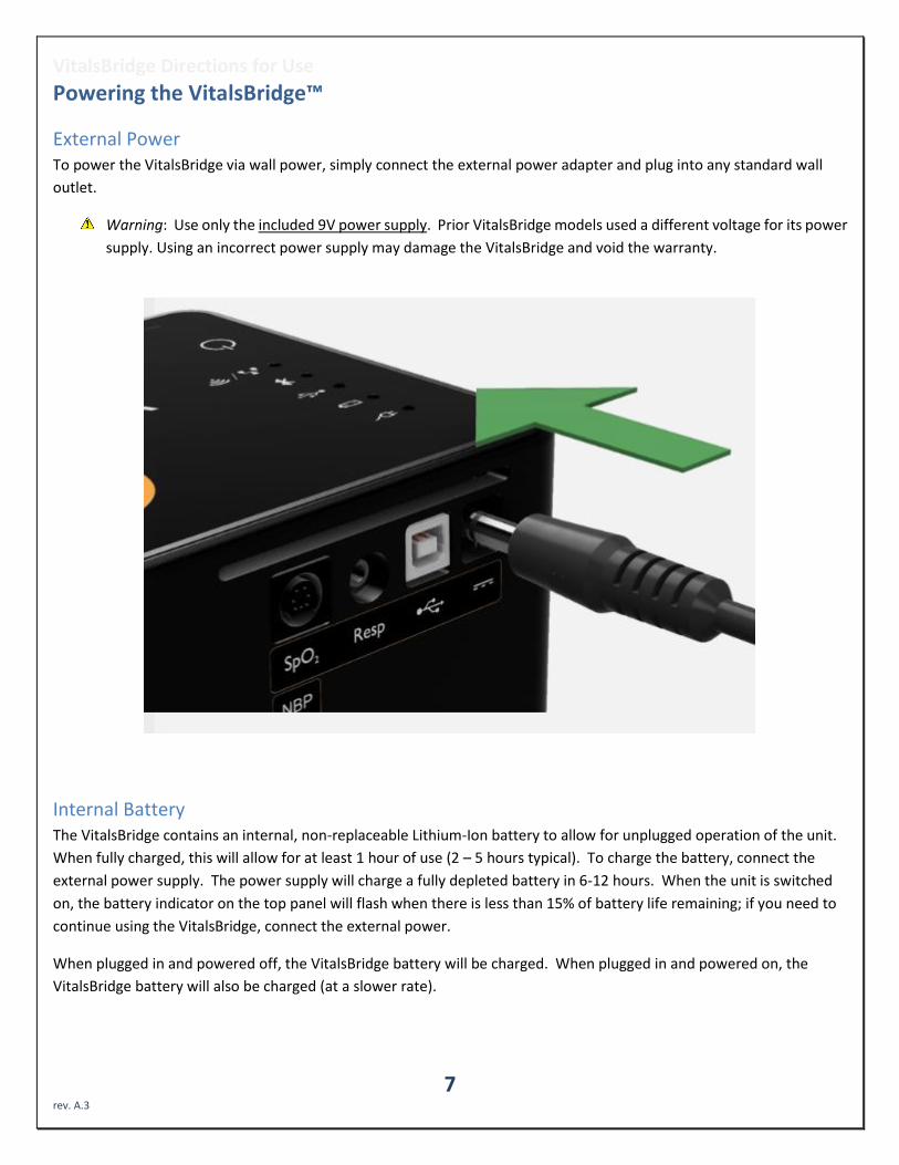
External Power To power the VitalsBridge via wall power, simply connect the external power adapter and plug into any standard wall
outlet.
Warning: Use only the included 9V power supply. Prior VitalsBridge models used a different voltage for its power
supply. Using an incorrect power supply may damage the VitalsBridge and void the warranty.
Internal Battery The VitalsBridge contains an internal, non-replaceable Lithium-Ion battery to allow for unplugged operation of the unit.
When fully charged, this will allow for at least 1 hour of use (2 – 5 hours typical). To charge the battery, connect the
external power supply. The power supply will charge a fully depleted battery in 6-12 hours. When the unit is switched
on, the battery indicator on the top panel will flash when there is less than 15% of battery life remaining; if you need to
continue using the VitalsBridge, connect the external power.
When plugged in and powered off, the VitalsBridge battery will be charged. When plugged in and powered on, the
VitalsBridge battery will also be charged (at a slower rate).

VitalsBridge Directions for Use
8 rev. A.3
VitalsBridge and Simulator Communication
Overview The VitalsBridge has several communication options (to connect the VitalsBridge to your PC):
All models:
• Bluetooth
• USB communication (RS-232)
VitalsBridge 200 and 300:
• Wifi
• Ethernet
Note: only one connection is needed. The directions for set-up of each method can be found below.
Note: The Wifi connection option cannot be used for initial set-up. Please select a different connection method the first
time.
Bluetooth To communicate with the VitalsBridge over Bluetooth, the VitalsBridge must first be paired with the Windows-based
computer or Android mobile device that has the VitalsBridge Connector application. Refer to your computer’s or mobile
device’s instructions on how to pair. The VitalsBridge will provide a 6-digit pin, which may need to be
confirmed/acknowledged during the pairing process. If this is the case, simply select “confirm” when the appropriate
screen appears (the number shown has no significant meaning associated with the VitalsBridge and does not need to be
compared to another number). Once paired, the VitalsBridge will be available for connection in the VitalsBridge
Connector Application.
USB (RS-232) With the supplied USB cable, connect the VitalsBridge to the Windows-based computer. Windows will automatically
install the appropriate drivers for RS-232 communication over USB. Consider restarting the computer prior to running
the VitalsBridge Connector application. Note: USB communication is unavailable on the VitalsBridge Connector for
mobile devices.
“Standardized Patient Setup”
“Running the VitalsBridge using a Serial Cable With a patient simulator”

VitalsBridge Directions for Use
9 rev. A.3
Wifi/Ethernet Communication The VitalsBridge may be connected to a router by an Ethernet cable or by Wifi (2.4 GHz 8.02.11b/g/n). The VitalsBridge
Connector software runs on a PC that is on the same network as the VitalsBridge and patient simulator (if applicable).
Ethernet:
When connecting the VitalsBridge to the patient simulator using an Ethernet cable, ensure the cable is functional and is
securely connected between the Ethernet ports of the VitalsBridge and the manikin.
Note: It is now possible for the VitalsBridge to be directly connected to a Windows PC that controls a patient simulator
with an Ethernet cable. The VitalsBridge is assigned one of the link-local addresses in the range 169.254.1.1 -
169.254.254.254. Some additional network configuration may be necessary for this to work.
Wifi:
Wifi communication for the VitalsBridge is possible only after it has been configured using the VitalsBridge Connector
software. Wifi configuration is completed with a Bluetooth or USB connection with the VitalsBridge. Wifi
communication cannot be used during the initial set-up.
Note: Instructions on how to set-up the VitalsBridge via Wifi are shown in the section for using the VitalsBridge
Connector Software. See page 21.

VitalsBridge Directions for Use
10 rev. A.3
Windows Network Settings Discovery of the VitalsBridge instrumentation uses the UDP network protocol on port 14998, while TCP/IP
communication occurs over port 14997. When running for the first time, please ensure you allow application access
through the Windows Firewall on both the public and private profiles.

VitalsBridge Directions for Use
11 rev. A.3
Installation of the VitalsBridge Connector Software The VitalsBridge software may be installed on a computer that that communicates with a patient simulator or to an
instance of “virtual manikin” software. Download the appropriate VitalsBridge Connector installation software from
vitalsbridge.com/downloads/. If necessary, copy the software to the computer on which it will be installed. Navigate to
the installation software file and open in. Follow the on-screen installation instructions. Upon successful installation, a
VitalsBridge icon will be created on the PC's desktop.
Note: Choose the appropriate VitalsBridge installation software carefully. There may be specific installation software
that is compatible with a particular version of a patient simulator (e.g., Laerdal LLEAP versus legacy versions of Laerdal
SimMan® 3G software, or the particular version of LLEAP).

VitalsBridge Directions for Use
12 rev. A.3
Connecting the VitalsBridge with a Patient Monitor This section will describe how to connect the cables and tubing between the VitalsBridge and the vital signs patient
monitor. The cable kit provided with the VitalsBridge is intended to be preconfigured with the vital signs monitor brand
and model you plan to use. If more than one vital signs monitor will be used, refer to www.vitalsbridge.com on how to
purchase additional cable kits.
Pulse Oximetry (SpO2) Pulse oximetry, or SpO2, is used to determine the oxygen saturation of a patient’s blood. It also will provide a pulse
measurement. SpO2 simulation by the VitalsBridge uses special circuitry in a custom SpO2 adapter/cable kit, which
provides expected levels to simulate the SpO2 probe according to the SpO2 value set in the simulator’s instructor
application. A SpO2 probe is supplied, which may be placed on a manikin’s or standardized patient’s finger; however,
this probe is not required for presenting a SpO2 value on the patient vital signs monitor. The custom SpO2 adapter has
labeled cable connections to both the VitalsBridge and the vital signs monitor. It is important to have the correct SpO2
adapter for the brand of SpO2 technology (e.g., Nellcor, Nellcor Oximax, Masimo, Philips).
A universal SpO2 adapter is also available for use with the VitalsBridge. It is similar to the other oximeter adapters,
except it uses the non-disposable SpO2 probe that is supplied with the patient monitor.
The universal SpO2 adapter does not have the same set-up as the other adapters (different from the figure). To attach,
connect the adapter box to the VitalsBridge with the cable that came packaged with the adapter box. Then clip the SpO2
probe (the one typically used with the monitor) into adapter box around the white plastic covered “finger.” Make sure
the probe is firmly and deeply secured around the “finger.” There may be some resistance as you push the probe down.
A disposable SpO2 probe is supplied with the universal adapter as well. This may be plugged into the adapter box and
placed on a manikin’s or standardized patient’s finger; however, this probe is not required for presenting a SpO2 value
on the patient vital signs monitor.

VitalsBridge Directions for Use
13 rev. A.3
Non-invasive Blood Pressure (NIBP) The VitalsBridge is capable of simulating non-invasive blood pressure by mimicking the pulsing of the artery. The NIBP
tubing from the patient monitor is connected to the VitalsBridge, and when the patient monitor initiates a NIBP reading,
it automatically detects the pressure and simulates an appropriate magnitude of pulsing.
The tubing connection from the patient monitor to the VitalsBridge may need configuration, depending on the style of
connector used with the patient monitor’s NIBP tubing. A tubing adapter and connectors have been included for
appropriate fitting(s) to connect the luer fitting on the VitalsBridge with the patient monitor’s NIBP tubing. If the NIBP
tubing contains 2 connectors, a 2-tube to 1 tube adapter fitting has been provided.
Configuration of VitalsGas Source (VB300 only) The VitalsGas, a regulated source of compressed CO2 is required for capnography. A 16g threaded CO2 cylinder may be
used or compressed CO2 from another external source may be available at your facility (wall source, a tank, etc). Consult
your facility's engineering regarding external CO2 sources and the appropriate regulators and adapters for correct and
safe connection.
Using the Portable VitalsGas Regulator: The portable VitalsGas regulator uses 16g threaded CO2 disposable cylinders.
The regulator may be detached by moving the regulator out of its bracket on the side of the VitalsBridge. The regulator’s
tubing has a luer lock fitting that will connect into the VitalsBridge, and regulator knob to control the flow of gas. The
regulator should be turned to the off position when it is not connected to the VitalsBridge via the luer connection. Only
turn the regulator on when a tight secure connection to the VitalsBridge has been verified.
Caution: The regulator should be kept horizontal to upright when the VitalsGas cylinder is attached. The cylinder
is pressurized. Sudden release of pressure may cause injury. Turn regulator to OFF when not in use.
Installing VitalsGas Cartridge:
1. If replacing a cartridge, temporarily remove the regulator from its bracket on the VitalsBridge instrumentation and remove the empty cartridge from the regulator by turning it counterclockwise. (if this is the first time installing a cartridge, the regulator should already be separated from its bracket and there should be no cartridge attached to it (unlike the figure below)).
VitalsBridge Directions for Use
14 rev. A.3
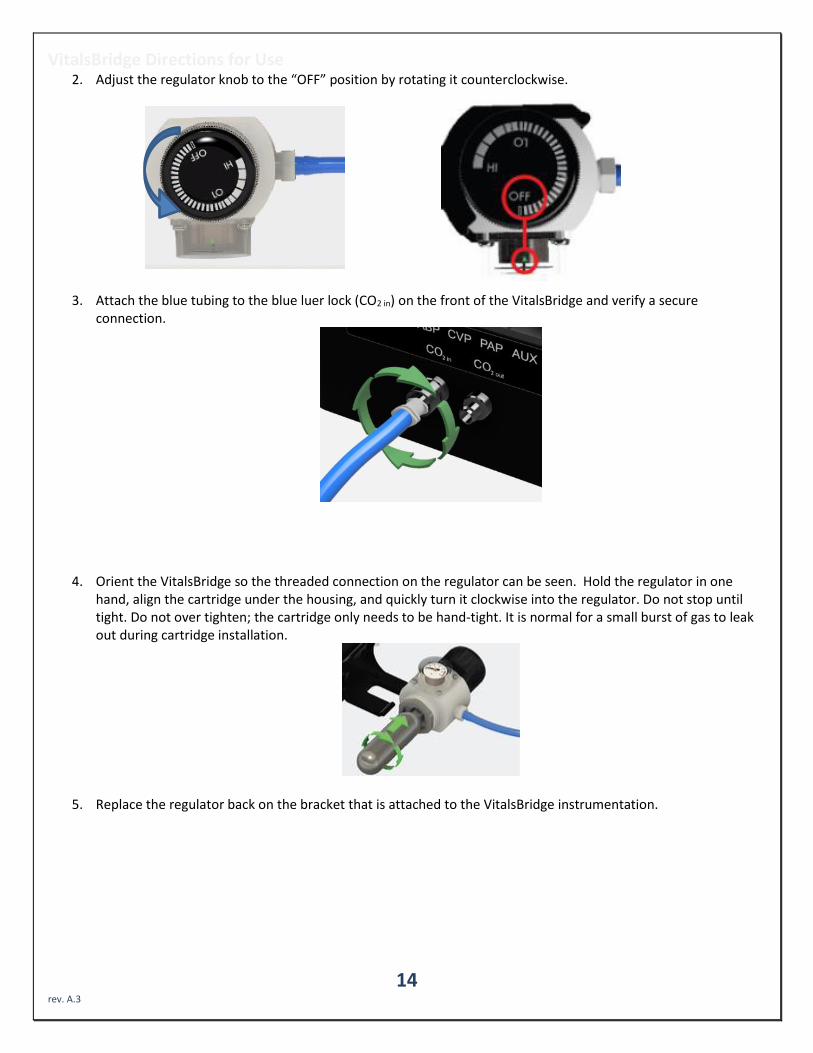
2. Adjust the regulator knob to the “OFF” position by rotating it counterclockwise.
3. Attach the blue tubing to the blue luer lock (CO2 in) on the front of the VitalsBridge and verify a secure connection.
4. Orient the VitalsBridge so the threaded connection on the regulator can be seen. Hold the regulator in one hand, align the cartridge under the housing, and quickly turn it clockwise into the regulator. Do not stop until tight. Do not over tighten; the cartridge only needs to be hand-tight. It is normal for a small burst of gas to leak out during cartridge installation.
5. Replace the regulator back on the bracket that is attached to the VitalsBridge instrumentation.

VitalsBridge Directions for Use
15 rev. A.3
6. SLOWLY turn the regulator knob clockwise until the pressure on the gauge reads 15-20 PSI. Do not set the regulator to a reading higher than 20 PSI.
Caution: Ensure VitalsGas has been fully released prior to disposing of the cartridge. This may be accomplished
by: (i) turning the regulator to “OFF”, (ii) detaching the female luer fitting from the blue luer lock ring on the
VitalsBridge, (iii) slowly turning the regulator knob clockwise (towards “HI”), and (iv) allowing the remaining
compressed gas to expel in a controlled manner. The cartridge may be very cold. Point the outlet of the
cartridge away from yourself and others. Wear eye protection. Ensure that the knob is turned to the off
position before a new cartridge is installed.
Caution: When not in use turn the regulator to the off position and disconnect the regulator tubing from the
VitalsBridge.
Warning: VitalsGas cartridges may become extremely cold when discharging. Protect eyes and hands when
installing and handling VitalsGas cartridges.
Warning: Mishandled VitalsGas cartridges may become projectiles.
Caution: VitalsGas cartridges may NOT be transported by air.
Capnography (Side-stream End Tidal CO2, VB300 only) The VitalsBridge is configured for simulating side-stream capnography. Capnography is the measurement of
concentration of patients’ exhaled CO2. The VitalsBridge utilizes a compressed CO2 source to provide a mixture
composed of the correct amount of air and CO2 to simulate the fraction of CO2 exhaled over each breath by a patient.
To use the capnography function, ensure that your patient monitor supports side-stream capnography measurement. If
it does, connect its capnography line to the luer fitting labeled “CO2 out” on the VitalsBridge.

VitalsBridge Directions for Use
16 rev. A.3
Invasive Blood Pressure (IBP) (VB300 only) The VitalsBridge is able to simultaneously simulate up to 3 different invasive blood pressure waveforms. These include
arterial blood pressure (ABP), central Venous pressure (CVP), pulmonary artery pressure (PAP) or pulmonary capillary
wedge pressure (PCWP). The VitalsBridge simulates the transducer output signal for each invasive blood pressure and
utilizes an RJ-11 cable to connect from the VitalsBridge to the patient monitor’s IBP cable. Note: contact Dynasthetics or
www.vitalsbridge.com for assistance with purchasing a VitalsBridge-compatible invasive blood pressure monitoring
cable (i.e., the cable that connects from the patient monitor to the VitalsBridge RJ-11 cable).
When using IBP, all waveforms are not required to for the VitalsBridge to function. Unused IBP ports on the VitalsBridge
may be left unconnected.
To side-stream CO2
connection on vital signs
monitor.
VitalsBridge Directions for Use
17 rev. A.3
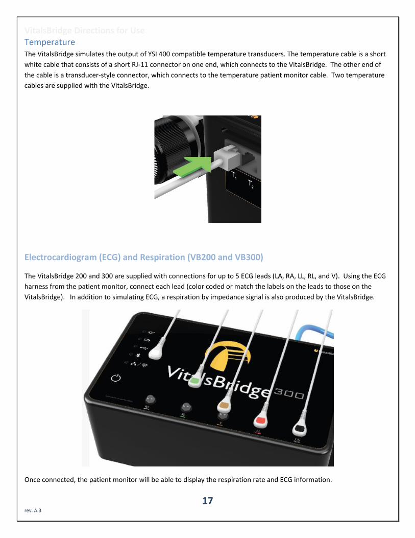
Temperature The VitalsBridge simulates the output of YSI 400 compatible temperature transducers. The temperature cable is a short
white cable that consists of a short RJ-11 connector on one end, which connects to the VitalsBridge. The other end of
the cable is a transducer-style connector, which connects to the temperature patient monitor cable. Two temperature
cables are supplied with the VitalsBridge.
Electrocardiogram (ECG) and Respiration (VB200 and VB300)
The VitalsBridge 200 and 300 are supplied with connections for up to 5 ECG leads (LA, RA, LL, RL, and V). Using the ECG
harness from the patient monitor, connect each lead (color coded or match the labels on the leads to those on the
VitalsBridge). In addition to simulating ECG, a respiration by impedance signal is also produced by the VitalsBridge.
Once connected, the patient monitor will be able to display the respiration rate and ECG information.
VitalsBridge Directions for Use
18 rev. A.3
Running the VitalsBridge™
There is a specific sequence for initializing and running the VitalsBridge. Assuming that both the VitalsBridge and patient
simulator are turned off, the summary of the steps are as follows:
1. Power on the patient simulator
2. Power on the patient simulator’s computer
3. Run the software that is used to control the patient simulator
4. Power on the VitalsBridge instrumentation.
5. Run the VitalsBridge Connector software
Step 1: Power on the patient simulator and wait until it is fully initialized. Refer to the simulator’s directions for use on
how to power on the manikin.
Step 2: Power on the computer used to control the patient simulator. Refer to the simulator’s directions for use on how
to power on the computer that is used to control the patient simulator.
Step 3: Run the software used to control the patient simulator. Refer to the simulator’s directions for use on how to
appropriately run the software used to control the patient simulator.
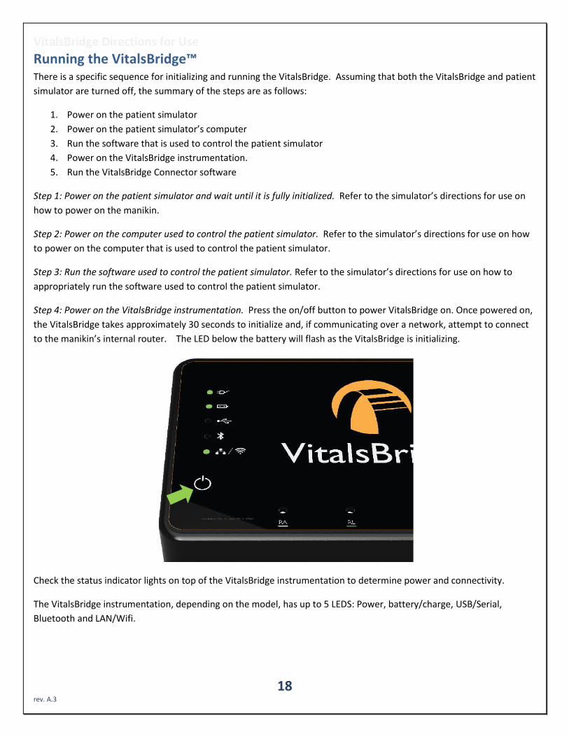
Step 4: Power on the VitalsBridge instrumentation. Press the on/off button to power VitalsBridge on. Once powered on,
the VitalsBridge takes approximately 30 seconds to initialize and, if communicating over a network, attempt to connect
to the manikin’s internal router. The LED below the battery will flash as the VitalsBridge is initializing.
Check the status indicator lights on top of the VitalsBridge instrumentation to determine power and connectivity.
The VitalsBridge instrumentation, depending on the model, has up to 5 LEDS: Power, battery/charge, USB/Serial,
Bluetooth and LAN/Wifi.

VitalsBridge Directions for Use
19 rev. A.3
- Power indicator:
o no light: switched off, or switched on and the VitalsBridge is not plugged into an outlet o solid: switched on and power available to the VitalsBridge
- Battery/charge indicator:
o no light: VitalsBridge is not running o solid: VitalsBridge is on, battery charge > 15% o flashing every 1 second: unit is running on low battery charge < 15%
- USB/Serial
o no light: usb is not ready o solid: usb is ready
- Bluetooth
o no light: bluetooth is not ready o solid: bluetooth is ready
- WLAN or LAN:
o no light: not connected to router o solid: VitalsBridge connected to the manikin’s internal router or to an external router
Step 5: Run the VitalsBridge Connector software: Double click on the VitalsBridge Connector icon, labeled VitalsBridge,
located on the computer's desktop.
Alternatively, the software may be located by searching for “VitalsBridge” using the Windows search
function (i.e., by pressing the button in Windows 7 and typing in the search dialog or by pressing +S
in Windows 8/10).
Once the Connector Application is running, any available Vitalsbridge units will appear in the Connection tab (connected
via Bluetooth, Serial, or Ethernet/Wifi for 200/300 units only). Select the correct VitalsBridge unit and pressthe
CONNECT button.
Note: If your Vitalsbridge does not appear in the list, close-out of the program and reopen the software. Make sure the
Vitalsbridge unit is turned on before opening the software.
VitalsBridge Directions for Use
20 rev. A.3
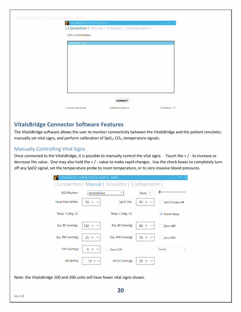
VitalsBridge Connector Software Features The VitalsBridge software allows the user to monitor connectivity between the VitalsBridge and the patient simulator,
manually set vital signs, and perform calibration of SpO2, CO2, temperature signals.
Manually Controlling Vital Signs Once connected to the VitalsBridge, it is possible to manually control the vital signs. Touch the + / - to increase or
decrease the value. One may also hold the + / - value to make rapid changes. Use the check boxes to completely turn
off any SpO2 signal, set the temperature probe to room temperature, or to zero invasive blood pressures.
Note: the VitalsBridge 100 and 200 units will have fewer vital signs shown.
VitalsBridge Directions for Use
21 rev. A.3
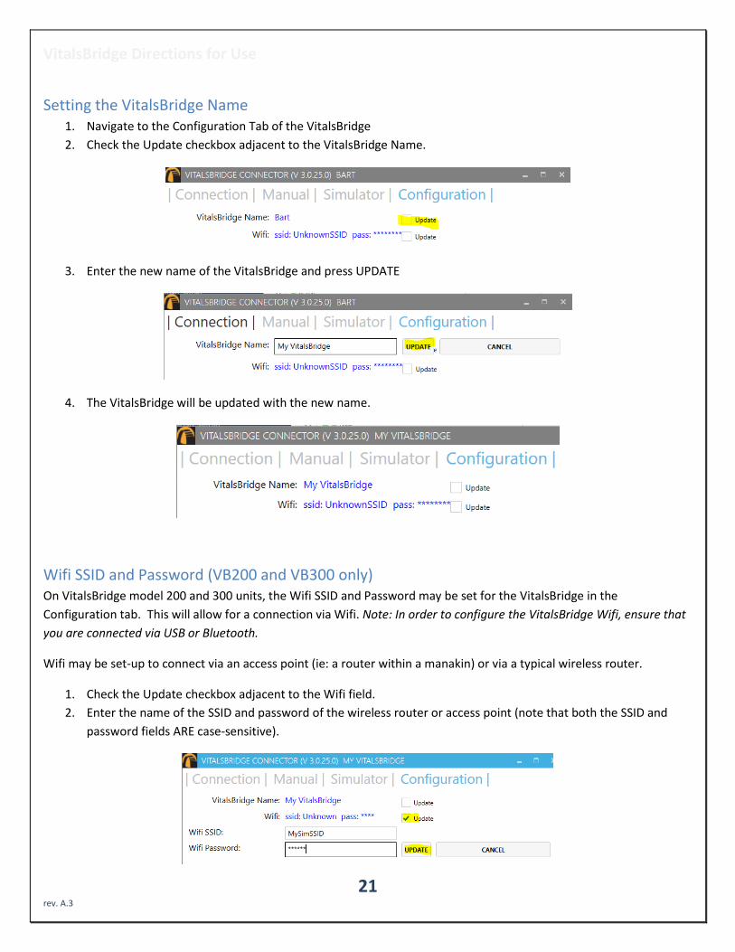
Setting the VitalsBridge Name 1. Navigate to the Configuration Tab of the VitalsBridge
2. Check the Update checkbox adjacent to the VitalsBridge Name.
3. Enter the new name of the VitalsBridge and press UPDATE
4. The VitalsBridge will be updated with the new name.
Wifi SSID and Password (VB200 and VB300 only) On VitalsBridge model 200 and 300 units, the Wifi SSID and Password may be set for the VitalsBridge in the
Configuration tab. This will allow for a connection via Wifi. Note: In order to configure the VitalsBridge Wifi, ensure that
you are connected via USB or Bluetooth.
Wifi may be set-up to connect via an access point (ie: a router within a manakin) or via a typical wireless router.
1. Check the Update checkbox adjacent to the Wifi field.
2. Enter the name of the SSID and password of the wireless router or access point (note that both the SSID and
password fields ARE case-sensitive).

VitalsBridge Directions for Use
22 rev. A.3
SpO2 Calibration The VitalsBridge is pre-calibrated with factory settings for a Nellcor standard probe. SpO2 Calibrations are stored on the
VitalsBridge. If the set SpO2 value significantly deviates from the value on the vitals sign monitor, then it is possible to
use your own calibration. To perform a new calibration, first ensure the adapter is configured correctly. Next, under the
Configuration Tab, Choose SpO2 under “Selected Calibration” and press the NEW button.
Note: When preforming a calibration, it works best if the disposable SpO2 probe supplied is NOT connected to the
adapter box.
(If the disposable SpO2 probe is connected, it needs to be on a finger or something of the like. While it does not take an
SpO2 reading of the thing it is surrounding (finger, manikin, etc…), a light sensor indicates that it is in use. If the light
sensor is not activated it will cause problems with the calibration.)
Choose a name for the calibration:
The user interface will instruct you to wait for a period of time and then to enter the SpO2 reading shown on the patient
monitor.
Note: wait until the SpO2 reading has stabilized on the monitor before entering the value. Some vital signs monitors will
filter and average the SpO2 value, and there may be a several second delay before the reading changes and stabilizes.

VitalsBridge Directions for Use
23 rev. A.3
Additional calibration entries are shown and the process of entering in a SpO2 value is repeated until enough points are
found for an accurate calibration reading. Once enough points are found, the calibration is automatically saved and
selected.
Unused custom calibrations may be removed by highlighting the desired calibration to remove and pressing the
REMOVE button.
CO2 Calibration (VB300 only) Calibration may be needed if the end-tidal CO2 reading on the patient vital signs monitor does not properly match the
CO2 waveform on the Instructor Application. CO2 calibration is performed in a similar manner as SpO2.
1. Select the CO2 radio button and press NEW.
2. Enter the name of the custom calibration
3. As per the instructions on the user interface, wait several seconds and enter the end-tidal CO2 value (mmHg)
shown on the patient monitor.
4. Repeat step 3 for a number of calibration points.

VitalsBridge Directions for Use
24 rev. A.3
Temperature Calibration Selection The default temperature calibration selection is appropriate for most critical care patient monitors. Select the Default
Temperature setting in the Configuration tab of the VitalsBridge Connector.
There are a few other non-custom calibrations provided for “Spot Check” monitors.
Obtaining a Temperature Reading on a “Spot-Check” Monitor 1. Choose the appropriate spot-check monitor from the list of temperature calibrations from the Calibration tab in
the VitalsBridge Connector.
2. Ensure the temperature probe on the spot-check monitor is placed in the cradle.
3. Ensure the “Room Temperature” checkbox on the VitalsBridge connector app is selected.
4. Take the temperature probe on the spot-check monitor from its cradle, followed by unchecking the “Room
Temperature” checkbox.
5. Wait for the monitor to take a reading.
Connecting to a Patient Simulator If the computer is able to connect to a patient simulator over a network, select the “Simulator” tab. Select the
appropriate patient simulator that is reported in the dialog box and select CONNECT.

VitalsBridge Directions for Use
25 rev. A.3
Once connected to a patient simulator, the Vital Signs for the patient simulator will be automatically sent to the
VitalsBridge, for presentation on a real monitor. Important: use the patient simulator’s application to control whether
ECG leads are placed, Capnography is enabled, and whether the SpO2 probe in place.
Zeroing the Invasive Blood Pressure(s) (VB300 only) IBPs may be zeroed by setting the blood pressure waveform to “Flat Line” in the software used to control your patient
simulator. Refer to your patient monitor's documentation for procedures of zeroing the pressures within the monitor's
user interface. Once the pressures are zeroed on the monitor, deselect and apply the “Flat Line” setting in the Instructor
Application to allow the waveforms to reappear. If the blood pressure readings differ significantly from the values set in
the Instructor Application, then attempt to re-zero.

VitalsBridge Directions for Use
26 rev. A.3
Step 1 (Simulator): In the simulator’s instructor application, locate where the waveform may be “zeroed” or “flatlined”.
-or-
Step 1 (Manual): In the Manual tab of the VitalsBridge connector, select the checkbox of the invasive blood pressure you
wish to zero.
Step 2: Use the patient monitor’s user interface and activate the zero function for the corresponding invasive pressure.
Consult your patient monitor’s user manual on instructions for how to zero an invasive blood pressure. Verify that the
zero has succeeded and is showing a value of 0 on the patient monitor.
Step 3: Uncheck the checkbox in the Manual tab from Step 1, or disable the zero on the patient simulator’s instructor
software.
Pulmonary Capillary Wedge Pressure Simulation (VB300 only) Simulation of wedging a small pulmonary artery by inflating a balloon to measure the pulmonary capillary wedge
pressure (PCWP) is accomplished by checking the PCWP checkbox in the Manual tab of the VitalsBridge connector. This
will send a PCWP waveform from the VitalsBridge to the vital signs monitor using the PAP connection. Adjust the value
of the PCWP value by using the + - on the VitalsBridge. If a patient simulator is generating the PCWP waveform, click the
checkbox on the Simulator tab to change the waveform from PAP

VitalsBridge Directions for Use
27 rev. A.3
VitalsBridge Frequently Asked Questions
General Use and Connectivity Q: Who do I contact for customer support? A: Please contact Dynasthetics LLC in the USA, phone: +1-435-200-3402 or +1-801-484-3820, email:
[email protected]. Also see www.vitalsbridge.com. Q: Is my monitor is compatible with the VitalsBridge? A: There are many different brands and thousands of different configurations of vital signs monitors. The VitalsBridge is
compatible with most brands and models. The VitalsBridge is compatible with side-stream capnography technology (not mainstream). The VitalsBridge requires some specific cables and configuration for a vital signs monitor’s non-invasive blood pressure cuff, SpO2, invasive blood pressure, and temperature. Refer to www.vitalsbridge.com for information on how to purchase VitalsBridge compatible patient monitor cables.
Q: Is the VitalsBridge compatible with Laerdal patient simulators that can run the LLEAP software? A: Yes, the VitalsBridge is LLEAP compatible. However, when installing the VitalsBridge software, ensure that the correct
version is chosen (i.e., choose the LLEAP compatible installer if running with LLEAP). Q: Is the VitalsBridge compatible with Laerdal patient simulators that run on SimPad? A: The VitalsBridge is not SimPad compatible. However, many Laerdal patient simulators that run on SimPad also run on
LLEAP, which is compatible with the VitalsBridge. Contact Laerdal for additional details. Q: How long will the VitalsBridge run on a fully charged battery? A: Typical running times are 1.5 to 4+ hours, depending on how often non-invasive blood pressure measurements are
made and whether capnography simulation is turned on in the VitalsBridge software. Q: What is the recommended sequence for starting the VitalsBridge? A: If you have been running the manikin for more than 30 minutes prior to starting the VitalsBridge, it is recommended
that you exit the Instructor Application software, and power off the manikin. Power on the patient simulator and wait for it to initialize fully, start the software that is used to control the patient simulator, power on the VitalsBridge, and start the VitalsBridge Connector application.
SpO2 Q: My monitor is not giving a SpO2 reading with the cable adapter kit that I received with my VitalsBridge. A: You may have an incorrect SpO2 cable kit. Please contact Dynasthetics support. Q: Is the VitalsBridge compatible with the Philips flexible finger-cot probe (M1191A) or Philips finger-clip style probe
(M1196A)? A: The SpO2 cable adapter kit provided with the VitalsBridge comes with its own finger-clip style probe which is used in
lieu of the probes supplied with the patient monitor. Q: There is a lot of noise on my SpO2 waveform reading. What is wrong? A: If you manikin has a RFID reader (e.g., for drug and airway management device recognition), try disabling the RFID
through the application that is used to control the patient simulator.
VitalsBridge Directions for Use
28 rev. A.3
Non-invasive Blood Pressure Q: I am not getting a reading from my non-invasive blood pressure monitor. What should I check? A: First check that the cable from the monitor is secure and not leaking at both the monitor’s connector and at the
VitalsBridge connector. Ensure that NIBP tubing and connections are not leaking. Ensure that none of the cuff tubes are kinked. Ensure that the VitalsBridge is running.
CO2 Q: How long will each VitalsGas cartridge last? A: When the VitalsBridge is running, a VitalsGas cartridge will last 8 hours or longer, depending on the simulation. When
the regulator is not in use, turn the regulator to off, disconnect the tubing connection from the luer fitting on the VitalsBridge and securely fit the cap on the end of the regulator tubing, without over tightening.
Q: My VitalsGas regulator has a partially full cartridge that I wish to empty and dispose, what do I do? A: Turn the regulator to off. Disconnect the regulator from the VitalsBridge by unscrewing the luer fitting. Hold the
tubing approximate 3-5 cm away from the end of the tubing. Slowly turn the knob on the regulator to let the gas escape at a low flow rate from the outlet of the regulator until no more gas release is heard or felt. Take care when removing the empty cartridge. It may be very cold.
Q: My monitor is not showing a CO2 waveform, what should I check? A: Check that the VitalsGas cartridge is not empty. Ensure the monitor uses side stream capnography. Ensure that the
CO2 sampling line is connected properly to the VitalsBridge and the monitor. Check that CO2 waveforms are enabled on the VitalsBridge software. Attempt to re-calibrate the CO2.
Q: My monitor shows a CO2 waveform and value that is extremely high (> 150 mmHg). What is wrong? A: Ensure that the CO2 checkbox on the VitalsBridge software app is selected. Ensure that the supply pressure to the
VitalsBridge is 35-40 PSI.
Invasive Blood Pressure Q: I see a blood pressure waveform on the vital signs monitor, but there is no number being shown. What is the
problem? A: The monitor’s blood pressure must be zeroed. In the software that is used to control the patient simulator, ensure
the invasive blood pressure waveform is set to “flat line” (i.e., the set pressure is a continuous value of zero over time). On the patient monitor, apply the “zero blood pressure” function, making certain you select the correct transducer. Disable “flat line” for the blood pressure waveform in the software that is used to control the patient simulator
Q: The invasive blood pressure readings on my monitor are inaccurate (more than 5-10 mmHg from the set value).
What is wrong? A: Ensure that the monitor has been properly zeroed by enabling the “flat line” feature on the invasive blood pressure
waveform of interest in the software that controls the patient simulator. Then use the zero blood pressure feature on the vital signs monitor (consult the vital signs monitor documentation).
Q: My monitor came with a cable that connects from the monitor to an invasive blood pressure transducer. However, it
does not fit the invasive blood pressure cables or connections on the VitalsBridge. How do I find the right connector? A: You may purchase the proper invasive blood pressure cable kit for your Vital Signs monitor that is compatible with the
VitalsBridge. Consult www.vitalsbridge.com (or e-mail [email protected]) for additional information.

VitalsBridge Directions for Use
29 rev. A.3
Q: How do I simulate a pulmonary-capillary wedge pressure with the VitalsBridge? A: Ensure the software that controls the patient simulator can send PCWP (e.g., pre-LLEAP Laerdal SimMan 3G’s are
incompatible with sending PCWP to the VitalsBridge). Then, follow the instructions on page 26
Respiration by ECG Impedance Q: I am using a 5-lead ECG on my simulator, but my simulator does not have connections for 5 leads. Will respiration
work? A: You may use the 5 ECG posts on the VitalsBridge (200 and 300 models only) to simulate an ECG with respiration
impedance.
Temperature Q: My monitor came with a cable that connects from the monitor to a temperature probe; however, it does not fit the
short, white, temperature cables that connect to the VitalsBridge. How do I find the right connector? A: You may purchase the proper temperature cable kit for your Vital Signs monitor. Consult www.vitalsbridge.com for
additional information.